

Page 1

OPERATOR’S
MANUAL
CAUTION:
* Before attempting to insert transistors capacitor thermocouple for testing, always be sure
that test lest leads have been disconnected from any measurement circuits.
* Components should not be connected to the hFE and capacitor and the thermocouple
socket when making voltage measure with test leads.
*Using this appliance in an environment with a strong radiated radio – frequency
electromagnetic field (approximately 3V/m), may influence its measuring accuracy. The
measuring result can be strongly deviating from the actual value.
CONTENTS PACE
1. Safety Information………………………………………………………………………….1
1.1 Preliminary………………………………………………………………………………1
During Use…………………………………………………….………………………..2
Symbols…………………………………………………………………………………3
Maintenance…………………………………………….…………….……………….4
2. Description………………………………………………..……..…………………………5
3. Operating Instruction………………………………..………….…………………………9
3.1 Measuring Voltage……………………………………….………………………….9
Measuring Current…………………………………….…………………………….9
Measuring Resistance……………………………………………………………..10
Testing Diode………………………………………………………………………..11
Testing Transistor………………………….……………………………….………..12
Continuity Test…………………………………….…………………………………12
Measuring Temperature…………………..………………………..……………..14
4. Specifications……………………………………………………….……………………13
5. Accessories………………………………………………………………………………20
5.1 Supplied with the Multimeter………………………………………………………20
How to use the Holster…………………………………………………………….20
6. Battery & Fuse Replacement………………………………………………………….22
Page 2

1. SAFETY INFORMATIONS
This multimeter has been designed according to IEC-1010 concerning electronic measuring
instruments with an overvoltage category (CATⅡ) and pollution 2.
Follow all safety and operating instructions to ensure that meter is used safely and is kept in
good operating condition.
1.1 PRELIMINARY
* When using this meter, the user must observe all normal safety rules concerning:
-
Protection against dangers of electronic current.
-
Protection of the meter against misuse.
* Full compliance with safety standards can be guaranteed only if used with test
leads supplied. If necessary, they must be replaced with the same model or same
electronic ratings. Measuring leads must be in good condition.
-1-
1.2 DURING USE
* Never exceed the protection limit values indicated in specifications for each range
of measurement.
* When the meter is linked to measurement circuit, do not touch unused terminals.
* When the value scale to be measured is unknown beforehand, set the range
selector at the highest position.
* Before rotating the range selector to change functions, disconnect test leads from
the circuit under test.
* When carrying out measurements on TV or switching power circuits, always
remember that there may be high amplitude voltage pulses at test points which can
damage the meter.
* Never perform resistance measurements on live circuits.
* Always be careful when working with voltage above 60V dc or 30V ac rms. Keep
fingers behind the probe barriers while measuring.
-2-
1.3 SYMBOLS
Important safety information, refer to the operating manual.
Dangerous voltage may be present.
Earth ground
Double insulation (protection classⅡ)
WARNING
* Before attempting to insert transistors for testing, always be sure that test leads have
been disconnected from any measurement circuits.
* Components should not be connected to the hFE and capacitor socket and the
thermocouple has been removed when making voltage measurements with test leads.
-3-
Page 3
1.4 MAINTENANCE
* Before opening the meter, always disconnect test leads from all sources of electric
current.
* For continue protection against fire, replace fuse only with the specified and current
rating:
F1: F2A / 250V F2: F 10A/250V
*If any faults or abnormalities are observed, the meter can not be used any more and
it has to be checked out.
*Never use the meter unless the back cover is in place and fastened fully.
*To clean the meter, use a damp cloth and mild detergent only, do not use abrasives
or solvents on it.
-4-
2. DESCRIPTION
This meter is a portable professional measuring instrument with 3 1/2 digit LCD,
capable of performing functions:
-
DC voltage measurement, 5 ranges from 200mV to 1000V
-
AC voltage measurement, 5 ranges from 200mV to 700V
-
DC current measurement, 7 ranges from 20μA to 10A
-
AC current measurement, 6 ranges from 200μA to 10A
-
Resistance measurement, 7 ranges from 200Ωto 200MΩ
-
Diode test
-
Transistor test
-
Audible continuity test
-5-
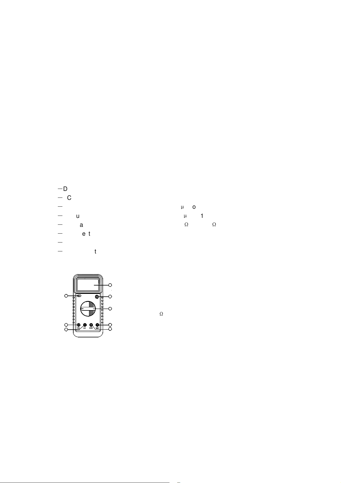
1. Power Switch
2. LCD Display
3. Transistor Testing Socket
4. Rotary Switch
5. V/Ω Input Jacks
6. COM Input Jack
7. A Input Jack
8. 10A Input Jack
-6-
Page 4

2.1
2.2
2.3
Function Red Lead Connection Input Limits
200mV
V & V~
Ω
A & A~
10A
FUNCTION AND RANGE SELECTOR
There are 8 functions and 32 ranges provided. A rotary switch is used to select
functions as well as ranges.
POWER SWITCH
A push-push switch is used to turn the meter on or off.
To extend the battery life, Auto Power- Off function is provided (Optional). The
meter will be turned off automatically within around 40 minutes. To turn on the meter
again, push the power switch to release it and then push it once more.
INPUT JACKS
This meter has four input jacks that are protected against overload to the limits
shown. During use connect the black test lead to COM jack and the red test lead as
shown below:
250V dc or rms ac
1000V dc, 700V ac (sine)
250V dc or rms ac
250V dc or rms ac
2A dc or rms ac
10Adc or rms ac
V /Ω
V /Ω
V/Ω
V/Ω
A
10A
-7-
Current range are protected by fuses
-8-
3. OPERATING INSTRUCTION
3.1 MEASURING VOLTAGE
3.2 MEASURING CURRENT
1. Connect the black lead to the COM jack and the red test lead to the A jack for a
1.Connect the black lead to the COM jack and the red test lest lead to the V/Ωjack.
2. Set the rotary switch at the desired V or V~ range position and connect test
leads across the source or load under measurement.
3. Read LCD display. The polarity of the red lead connection will be indicated when
making a dc measurement.
4. When only the figure”1” is displayed, it indicates overrange situation and the
higher range have to be selected.
maximum of 2A. For a max of 10A, move the red lead to the A jack.
-9-
Page 5

2. Set the rotary switch at desired A or A~ range position and connect test leads
jack.
2. Determine whether the transistor is NPN or PNP type and locate the Emitter. Base
and Collectors. Insert leads of the transistor into proper holes of the testing socket on
jack.
in series with the load under measurement.
3. Read LCD display. The polarity of the red lead connection will be indicated when
making a DC measurement.
4. When only the figure”1” displayed, it indicates overrange situation and the higher
range has to be selected.
3.3 MEASURING RESISTANGE
1. Connect the black test lead to the COM jack and the read to the V/Ωjack. (NOTE:
The polarity of red lead connection is positive〝+〞)
2. Set the rotary switch at desired Ω position and connect test leads across the
resistor under measurement. Read LCD display.
Note:
1. For resistance above 1MΩ, the meter may take a few seconds to get stable
reading.
-10-
3.4 TESTING DIODE
3.5 TESTING TRANSISTOR
1. Set the rotary switch at hFE position.
2. When the input is not connected,i.e. at open circuit, the figure “1” will be
displayed for the overrange condition.
3.. When checking in – circuit resistance, be sure the circuit under test has all power
removed and that all capacitors are fully discharged.
4. At 200MΩ range display reading is around 10 counts when test leads are
Shorted. These counts have to be subtracted from measuring results. For example,
when measuring 100MΩ resistance the display reading will be 101.0 and the
correct measuring result should be 101.0-1.0=100.0MΩ.
1. Connect the black test lead to COM jack and the red test lead to the V
( NOTE: The polarity of red lead connection is positive〝+〞)
2. Set the rotary switch at position and connect the red lead to the anode, the
black lead to the cathode of the diode under testing .The meter will show the
approx. forward voltage of the diode. If the lead connection is reversed. only figure
〝1〞
will be displayed.
Ω
-11-
the front panel.
3. LCD display will show the approximate hFE value at the test condition of base
current 10μA and Vce 3.2V.
WARNING
Before attempting to insert transistors for testing, always be sure that test leads
have been disconnected from any measurement circuits. Components should not
be connected to the hFE socket when making voltage measurements with test
leads.
3.6 CONTINUTITY TEST
1. Connect the black test lead to the COM jack and the red test lead to the V/
2. Set the rotary switch at position and connect test leads across two points of
the circuit under testing. If continuity exists (i.e., resistance less than about 70Ω),
built - in buzzer will sound.
Ω
Page 6

-12-
4. SPECIFICATIONS
Accuracy is specified for a period of one year after calibration and at 18℃ to 28℃ (64℉ to
82℉) with relative humidity to 80%.
GENERAL
Maximum Voltage between Terminals
And Earth Ground
Fuse Protection
Power Supply
Display
Measuring Method
Overrange Indication
Polarity Indication
Low Battery Indication
Operating Temperature
Storage Temperature
Size (Hxwxl)
Weight
4.2 DC VOLTAGE
Range Resolution Accuracy
200mV
2V
20V
200V
1000V
0.1mv
1mV
10mV
0.1V
1V
1000V dc or 700V rms ac (sine)
A: F 2A/250V 10A: F 10A/250V
9V battery, Neda 1604 or 6F22
LCD, 1999 counts max.,, updates 2-3/sec
Dual-slope integration A/D converter
〝1〞
display only
〝-〞
displayed for automatically
“ ”appears on the display
0℃ to 40℃(32℉ to 104℉)
-10℃ to 50℃(10℉ to 122℉)
91mm×189mm×31.5mm
310g(including battery)
±
0.5% of rdg ± 1 digit
±
0.5% of rdg ± 1 digit
±
0.5% of rdg ± 1 digit
±
0.5% of rdg ± 1 digit
±
0.8% of rdg ± 2 digits
-13-
Input impedance:10MΩ
-14-
4.3 AC VOLTAGE
Range Resolution Accuracy
200mV
2V
20V
200V
700V
Input impedance: 10MΩ
Frequency Range: 40Hz to 400Hz
Response: Average, calibrated in rms of sine wave
0.1mv
1mV
10mV
0.1V
1V
±
1.2% of rdg ± 3 digits
±
0.8% of rdg ± 3 digits
±
0.8% of rdg ± 3 digits
±
0.8% of rdg ± 3 digits
±
1.2% of rdg ± 3 digits
-15-
Page 7

4.4 DC CURRENT
Range Resolution Accuracy Burden Voltage
20μA
200μA
2mA
20mA
200mA
2A
10A
Overload Protection: F 2A fuse for 20μA to 2A ranges, F 10A fuse for 10A range.
-16-
4.5 AC CURRENT
Range Resolution Accuracy Burden Voltage
200μA
2mA
20mA
200mA
2A
10A
Overload Protection: F 2A fuse for 20μA to 2A ranges, F 10A fuse for 10A range.
Frequency Range: 40Hz to 400Hz
Response:Average, Calibrated in rms of sine wave
4.6 RESISTANCE
Range Resolution Accuracy
200Ω
2KΩ
20KΩ
200KΩ
2MΩ
20MΩ
200MΩ
Note: On 200MΩ range, if short input, display will read 1 MΩ, this 1MΩ should be
subtracted from measurement results.
-18-
4.7 DIODE
Range Description Test Condition
4.8 CONTINUITY
Range Description
0.01μA
0.1μA
1μA
10μA
0.1mA
2A
10mA
0.1μA
1μA
10μA
0.1mA
1mA
10mA
0.1Ω
1Ω
10Ω
100Ω
1KΩ
10KΩ
100KΩ
±
2.0% of rdg ± 5 digits
±
0.8% of rdg ± 1 digit
±
0.8% of rdg ± 1 digit
±
0.8% of rdg ± 1 digit
±
1.5% of rdg ± 1 digit
±
1.5% of rdg ± 1 digit
±
2.0% of rdg ± 5 digit
±
1.8% of rdg ± 3 digits
±
1.0% of rdg ± 3 digits
±
1.0% of rdg ± 3 digits
±
1.8% of rdg ± 3 digits
±
1.8% of rdg ± 3 digits
±
3.0% of rdg ± 7 digits
±
0.8% of rdg ± 3 digits
±
0.8% of rdg ± 1 digit
±
0.8% of rdg ± 1 digit
±
0.8% of rdg ± 1 digit
±
0.8% of rdg ± 1 digit
±
1.0% of rdg ± 1 digit
±
5.0% of (rdg –10 digits)± 10digits
Shows the approximate
forward voltage drop
Built-in buzzer will sound, if the resistance under test is less
than about 70Ω
10mV/μA
1.0mV/μA
100mV/mA
11mV/mA
2.0mV/mA
0.4V/A
0.03V/A
1.0mV/μA
100mV/mA
11mV/mA
2.0mV/mA
0.4V/A
0.03V/A
-17-
Forward Current 1mA
Vce 3.2V
Page 8

-19-
the back
5. ACCESSORIES
5.1 SUPPLIED WITH THE MUL TIMETER
Test leads Electric Rating 1000V, 10A MASTECH HYTL- 60
Battery 9V NEDA 1604 or 6F22
Operating Manual HYS004240
Holster HYHT-60
5.2 How to use the holster
The holster is used to protect the meter and to make the measurement more comfortable.
It comes with two stands installed together. The figure shows how to use the holster to:
a.
b.
c.
d.
-20-
6. BATTERY & FUSE REPLACEMENT
If the sign” ”appears on the LCD display, it indicates that battery should be replaced.
Remove screws on the back cover and open the case. Replace the exhausted battery with a
new one.
Fuse rarely need replacement and blow almost always as a result of the operator’s error.
Open the case as mentioned above, and then take the PCB out from the front cover. Replace
the blown fuse with same ratings.
Before attempting to open the case, be sure that test leads have been disconnected from
measurement circuits to avoid electric shock hazard.
For protection against fire, replace fuse only with specified ratings:
F1: F 2A/250V F2: F 10A/250V
-22-
Support the meter with a standard angle.
Support the meter with a small angle using the little stand
Hang the meter on the wall using the little stand. Take the little stand off from
side of the large stand and insert it into holes located upper on the holster.
Hold test leads.
WARNING
 Loading...