

Page 1

1. Table of Contents . . . . . . . . . . . . . . . . . . . . . . . . . . . . . . . . . . . . . . . . . . . . . . . . . . . . . . . . . . . . . . . . . . . . . . . . . . . . . . . . . . . . . . . . . . . . 3
1.1 01.0 Introduction . . . . . . . . . . . . . . . . . . . . . . . . . . . . . . . . . . . . . . . . . . . . . . . . . . . . . . . . . . . . . . . . . . . . . . . . . . . . . . . . . . . . . . . . 5
1.1.1 1.6 ProJet™ Systems Software . . . . . . . . . . . . . . . . . . . . . . . . . . . . . . . . . . . . . . . . . . . . . . . . . . . . . . . . . . . . . . . . . . . . . . . 5
1.1.2 1.1 About this Guide . . . . . . . . . . . . . . . . . . . . . . . . . . . . . . . . . . . . . . . . . . . . . . . . . . . . . . . . . . . . . . . . . . . . . . . . . . . . . . . . 5
1.1.3 1.2 Copyright . . . . . . . . . . . . . . . . . . . . . . . . . . . . . . . . . . . . . . . . . . . . . . . . . . . . . . . . . . . . . . . . . . . . . . . . . . . . . . . . . . . . . . 5
1.1.4 1.3 Useful Documents . . . . . . . . . . . . . . . . . . . . . . . . . . . . . . . . . . . . . . . . . . . . . . . . . . . . . . . . . . . . . . . . . . . . . . . . . . . . . . . 6
1.1.5 1.4 What's Inside . . . . . . . . . . . . . . . . . . . . . . . . . . . . . . . . . . . . . . . . . . . . . . . . . . . . . . . . . . . . . . . . . . . . . . . . . . . . . . . . . . . 6
1.1.6 1.5 Features and Benefits . . . . . . . . . . . . . . . . . . . . . . . . . . . . . . . . . . . . . . . . . . . . . . . . . . . . . . . . . . . . . . . . . . . . . . . . . . . . 6
1.1.6.1 1.5.1 Description and Definitions . . . . . . . . . . . . . . . . . . . . . . . . . . . . . . . . . . . . . . . . . . . . . . . . . . . . . . . . . . . . . . . . . . 8
1.1.7 1.7 Packaging . . . . . . . . . . . . . . . . . . . . . . . . . . . . . . . . . . . . . . . . . . . . . . . . . . . . . . . . . . . . . . . . . . . . . . . . . . . . . . . . . . . . . 9
1.2 02.0 Safety Symbols & Definitions . . . . . . . . . . . . . . . . . . . . . . . . . . . . . . . . . . . . . . . . . . . . . . . . . . . . . . . . . . . . . . . . . . . . . . . . . . 9
1.3 03.0 Safety Guidelines . . . . . . . . . . . . . . . . . . . . . . . . . . . . . . . . . . . . . . . . . . . . . . . . . . . . . . . . . . . . . . . . . . . . . . . . . . . . . . . . . . . 9
1.3.1 3.1 General . . . . . . . . . . . . . . . . . . . . . . . . . . . . . . . . . . . . . . . . . . . . . . . . . . . . . . . . . . . . . . . . . . . . . . . . . . . . . . . . . . . . . . . 10
1.3.2 3.2 Electrical . . . . . . . . . . . . . . . . . . . . . . . . . . . . . . . . . . . . . . . . . . . . . . . . . . . . . . . . . . . . . . . . . . . . . . . . . . . . . . . . . . . . . . 10
1.3.3 3.3 Ultraviolet (UV) Light . . . . . . . . . . . . . . . . . . . . . . . . . . . . . . . . . . . . . . . . . . . . . . . . . . . . . . . . . . . . . . . . . . . . . . . . . . . . . 10
1.4 04.0 Build Material Safety . . . . . . . . . . . . . . . . . . . . . . . . . . . . . . . . . . . . . . . . . . . . . . . . . . . . . . . . . . . . . . . . . . . . . . . . . . . . . . . . . 11
1.4.1 4.1 Disposal . . . . . . . . . . . . . . . . . . . . . . . . . . . . . . . . . . . . . . . . . . . . . . . . . . . . . . . . . . . . . . . . . . . . . . . . . . . . . . . . . . . . . . . 11
1.4.2 4.2 Health Hazards . . . . . . . . . . . . . . . . . . . . . . . . . . . . . . . . . . . . . . . . . . . . . . . . . . . . . . . . . . . . . . . . . . . . . . . . . . . . . . . . . 12
1.4.3 4.3 Material Handling . . . . . . . . . . . . . . . . . . . . . . . . . . . . . . . . . . . . . . . . . . . . . . . . . . . . . . . . . . . . . . . . . . . . . . . . . . . . . . . 13
1.4.4 4.4 Personal Protection Equipment . . . . . . . . . . . . . . . . . . . . . . . . . . . . . . . . . . . . . . . . . . . . . . . . . . . . . . . . . . . . . . . . . . . . . 13
1.4.5 4.5 Regulatory Information . . . . . . . . . . . . . . . . . . . . . . . . . . . . . . . . . . . . . . . . . . . . . . . . . . . . . . . . . . . . . . . . . . . . . . . . . . . 14
1.4.6 4.6 Spilled VisiJet® Material . . . . . . . . . . . . . . . . . . . . . . . . . . . . . . . . . . . . . . . . . . . . . . . . . . . . . . . . . . . . . . . . . . . . . . . . . . 14
1.4.7 4.7 Waste Removal . . . . . . . . . . . . . . . . . . . . . . . . . . . . . . . . . . . . . . . . . . . . . . . . . . . . . . . . . . . . . . . . . . . . . . . . . . . . . . . . . 14
1.4.8 4.8 Material Storage . . . . . . . . . . . . . . . . . . . . . . . . . . . . . . . . . . . . . . . . . . . . . . . . . . . . . . . . . . . . . . . . . . . . . . . . . . . . . . . . 15
1.5 05.0 System Requirements . . . . . . . . . . . . . . . . . . . . . . . . . . . . . . . . . . . . . . . . . . . . . . . . . . . . . . . . . . . . . . . . . . . . . . . . . . . . . . . . 16
1.6 06.0 Familiarization . . . . . . . . . . . . . . . . . . . . . . . . . . . . . . . . . . . . . . . . . . . . . . . . . . . . . . . . . . . . . . . . . . . . . . . . . . . . . . . . . . . . . . 16
1.6.1 6.1 System Functions . . . . . . . . . . . . . . . . . . . . . . . . . . . . . . . . . . . . . . . . . . . . . . . . . . . . . . . . . . . . . . . . . . . . . . . . . . . . . . . 18
1.7 07.0 Modeler Setup . . . . . . . . . . . . . . . . . . . . . . . . . . . . . . . . . . . . . . . . . . . . . . . . . . . . . . . . . . . . . . . . . . . . . . . . . . . . . . . . . . . . . . 18
1.7.1 7.1 Power on Modeler . . . . . . . . . . . . . . . . . . . . . . . . . . . . . . . . . . . . . . . . . . . . . . . . . . . . . . . . . . . . . . . . . . . . . . . . . . . . . . . 19
1.7.2 7.2 Add Cartridge and Install Build Platform . . . . . . . . . . . . . . . . . . . . . . . . . . . . . . . . . . . . . . . . . . . . . . . . . . . . . . . . . . . . . . 20
1.7.3 7.3 Install and Run ProJet™ 3-D Modeling Client Software . . . . . . . . . . . . . . . . . . . . . . . . . . . . . . . . . . . . . . . . . . . . . . . . . . 21
1.7.4 7.4 Create STL File(s) to Build . . . . . . . . . . . . . . . . . . . . . . . . . . . . . . . . . . . . . . . . . . . . . . . . . . . . . . . . . . . . . . . . . . . . . . . . 23
1.7.5 7.5 Submit Test Build . . . . . . . . . . . . . . . . . . . . . . . . . . . . . . . . . . . . . . . . . . . . . . . . . . . . . . . . . . . . . . . . . . . . . . . . . . . . . . . 24
1.7.6 7.6 Build Demo . . . . . . . . . . . . . . . . . . . . . . . . . . . . . . . . . . . . . . . . . . . . . . . . . . . . . . . . . . . . . . . . . . . . . . . . . . . . . . . . . . . . 25
1.8 08.0 Operations . . . . . . . . . . . . . . . . . . . . . . . . . . . . . . . . . . . . . . . . . . . . . . . . . . . . . . . . . . . . . . . . . . . . . . . . . . . . . . . . . . . . . . . . . 25
1.8.1 8.1 Preview Build Job . . . . . . . . . . . . . . . . . . . . . . . . . . . . . . . . . . . . . . . . . . . . . . . . . . . . . . . . . . . . . . . . . . . . . . . . . . . . . . . 25
1.8.2 8.2 Save a Build Job . . . . . . . . . . . . . . . . . . . . . . . . . . . . . . . . . . . . . . . . . . . . . . . . . . . . . . . . . . . . . . . . . . . . . . . . . . . . . . . . 29
1.8.3 8.3 Submit a Build Job . . . . . . . . . . . . . . . . . . . . . . . . . . . . . . . . . . . . . . . . . . . . . . . . . . . . . . . . . . . . . . . . . . . . . . . . . . . . . . 30
1.8.3.1 8.3.1 Remove Build Platform . . . . . . . . . . . . . . . . . . . . . . . . . . . . . . . . . . . . . . . . . . . . . . . . . . . . . . . . . . . . . . . . . . . . . 35
1.8.4 8.4 Manage Build Jobs . . . . . . . . . . . . . . . . . . . . . . . . . . . . . . . . . . . . . . . . . . . . . . . . . . . . . . . . . . . . . . . . . . . . . . . . . . . . . . 35
1.8.4.1 8.4.1 Delete Build Jobs . . . . . . . . . . . . . . . . . . . . . . . . . . . . . . . . . . . . . . . . . . . . . . . . . . . . . . . . . . . . . . . . . . . . . . . . . 37
1.8.4.2 8.4.2 Pause Build Job . . . . . . . . . . . . . . . . . . . . . . . . . . . . . . . . . . . . . . . . . . . . . . . . . . . . . . . . . . . . . . . . . . . . . . . . . . 38
1.8.4.3 8.4.3 Abort Build Job . . . . . . . . . . . . . . . . . . . . . . . . . . . . . . . . . . . . . . . . . . . . . . . . . . . . . . . . . . . . . . . . . . . . . . . . . . . 39
1.8.4.4 8.4.4 Repeat Build Job . . . . . . . . . . . . . . . . . . . . . . . . . . . . . . . . . . . . . . . . . . . . . . . . . . . . . . . . . . . . . . . . . . . . . . . . . 40
1.8.5 8.5 Modeler Status . . . . . . . . . . . . . . . . . . . . . . . . . . . . . . . . . . . . . . . . . . . . . . . . . . . . . . . . . . . . . . . . . . . . . . . . . . . . . . . . . 41
1.8.6 8.6 Empty Waste Drawer . . . . . . . . . . . . . . . . . . . . . . . . . . . . . . . . . . . . . . . . . . . . . . . . . . . . . . . . . . . . . . . . . . . . . . . . . . . . 41
1.8.7 8.7 Shutdown Modeler . . . . . . . . . . . . . . . . . . . . . . . . . . . . . . . . . . . . . . . . . . . . . . . . . . . . . . . . . . . . . . . . . . . . . . . . . . . . . . 42
1.8.8 8.8 Remove Part from Build Platform . . . . . . . . . . . . . . . . . . . . . . . . . . . . . . . . . . . . . . . . . . . . . . . . . . . . . . . . . . . . . . . . . . . 44
1.8.9 8.9 3D Modeling Batch Submission for Production Environment . . . . . . . . . . . . . . . . . . . . . . . . . . . . . . . . . . . . . . . . . . . . . . 44
1.8.10 8.10 Shrink Compensation for ProJet VisiJet® Materials . . . . . . . . . . . . . . . . . . . . . . . . . . . . . . . . . . . . . . . . . . . . . . . . . . . 50
1.9 09.0 Maintenance . . . . . . . . . . . . . . . . . . . . . . . . . . . . . . . . . . . . . . . . . . . . . . . . . . . . . . . . . . . . . . . . . . . . . . . . . . . . . . . . . . . . . . . 51
1.9.1 9.1 Cleaning Surfaces . . . . . . . . . . . . . . . . . . . . . . . . . . . . . . . . . . . . . . . . . . . . . . . . . . . . . . . . . . . . . . . . . . . . . . . . . . . . . . . 51
1.9.2 9.2 Cleaning the Waste Drawer . . . . . . . . . . . . . . . . . . . . . . . . . . . . . . . . . . . . . . . . . . . . . . . . . . . . . . . . . . . . . . . . . . . . . . . 52
1.9.3 9.3 Preventive Maintenance . . . . . . . . . . . . . . . . . . . . . . . . . . . . . . . . . . . . . . . . . . . . . . . . . . . . . . . . . . . . . . . . . . . . . . . . . . 53
1.9.4 9.4 Return Modeler for Repair . . . . . . . . . . . . . . . . . . . . . . . . . . . . . . . . . . . . . . . . . . . . . . . . . . . . . . . . . . . . . . . . . . . . . . . . . 53
1.10 10.0 Error Messages . . . . . . . . . . . . . . . . . . . . . . . . . . . . . . . . . . . . . . . . . . . . . . . . . . . . . . . . . . . . . . . . . . . . . . . . . . . . . . . . . . . . 53
1.10.1 10.1 Build Messages . . . . . . . . . . . . . . . . . . . . . . . . . . . . . . . . . . . . . . . . . . . . . . . . . . . . . . . . . . . . . . . . . . . . . . . . . . . . . . . 54
1.10.2 10.2 Material Messages . . . . . . . . . . . . . . . . . . . . . . . . . . . . . . . . . . . . . . . . . . . . . . . . . . . . . . . . . . . . . . . . . . . . . . . . . . . . 54
1.10.3 10.3 Status and Message Lines . . . . . . . . . . . . . . . . . . . . . . . . . . . . . . . . . . . . . . . . . . . . . . . . . . . . . . . . . . . . . . . . . . . . . . 55
1.11 11.0 Troubleshooting . . . . . . . . . . . . . . . . . . . . . . . . . . . . . . . . . . . . . . . . . . . . . . . . . . . . . . . . . . . . . . . . . . . . . . . . . . . . . . . . . . . 57
1.11.1 11.1 Communication Errors . . . . . . . . . . . . . . . . . . . . . . . . . . . . . . . . . . . . . . . . . . . . . . . . . . . . . . . . . . . . . . . . . . . . . . . . . . 57
1.11.2 11.2 Head Maintenance Station Errors . . . . . . . . . . . . . . . . . . . . . . . . . . . . . . . . . . . . . . . . . . . . . . . . . . . . . . . . . . . . . . . . . 58
1.11.3 11.3 Material Feed and Waste System Errors . . . . . . . . . . . . . . . . . . . . . . . . . . . . . . . . . . . . . . . . . . . . . . . . . . . . . . . . . . . 58
1.11.4 11.4 Material Quality Guarantee Errors . . . . . . . . . . . . . . . . . . . . . . . . . . . . . . . . . . . . . . . . . . . . . . . . . . . . . . . . . . . . . . . . . 58
1.11.5 11.5 Material Waste Errors . . . . . . . . . . . . . . . . . . . . . . . . . . . . . . . . . . . . . . . . . . . . . . . . . . . . . . . . . . . . . . . . . . . . . . . . . . 59
1.11.6 11.6 Motion System Errors . . . . . . . . . . . . . . . . . . . . . . . . . . . . . . . . . . . . . . . . . . . . . . . . . . . . . . . . . . . . . . . . . . . . . . . . . . 59
1.11.7 11.7 UV Subsystem Errors . . . . . . . . . . . . . . . . . . . . . . . . . . . . . . . . . . . . . . . . . . . . . . . . . . . . . . . . . . . . . . . . . . . . . . . . . . 59
1.11.8 11.8 Vacuum Regulator Errors . . . . . . . . . . . . . . . . . . . . . . . . . . . . . . . . . . . . . . . . . . . . . . . . . . . . . . . . . . . . . . . . . . . . . . . 60
1.11.9 11.9 Power Outage . . . . . . . . . . . . . . . . . . . . . . . . . . . . . . . . . . . . . . . . . . . . . . . . . . . . . . . . . . . . . . . . . . . . . . . . . . . . . . . . 60
1.12 12.0 Finishing . . . . . . . . . . . . . . . . . . . . . . . . . . . . . . . . . . . . . . . . . . . . . . . . . . . . . . . . . . . . . . . . . . . . . . . . . . . . . . . . . . . . . . . . . 61
1.13 13.0 Projet™ Spare Parts List . . . . . . . . . . . . . . . . . . . . . . . . . . . . . . . . . . . . . . . . . . . . . . . . . . . . . . . . . . . . . . . . . . . . . . . . . . . . . 61
1.13.1 13.1 Consumables and Replacement Modules . . . . . . . . . . . . . . . . . . . . . . . . . . . . . . . . . . . . . . . . . . . . . . . . . . . . . . . . . . . 61
1.14 14.0 Other Documents . . . . . . . . . . . . . . . . . . . . . . . . . . . . . . . . . . . . . . . . . . . . . . . . . . . . . . . . . . . . . . . . . . . . . . . . . . . . . . . . . . 61
1.14.1 14.1 Parts Finisher User Guide . . . . . . . . . . . . . . . . . . . . . . . . . . . . . . . . . . . . . . . . . . . . . . . . . . . . . . . . . . . . . . . . . . . . . . . 61
1.14.2 14.2 Material Safety Data Sheets (MSDS) . . . . . . . . . . . . . . . . . . . . . . . . . . . . . . . . . . . . . . . . . . . . . . . . . . . . . . . . . . . . . . 61
Page 2

1.14.3 14.3 Projet™ Quick Reference Guide . . . . . . . . . . . . . . . . . . . . . . . . . . . . . . . . . . . . . . . . . . . . . . . . . . . . . . . . . . . . . . . . . . 61
1.14.4 14.4 Facility Requirements Guide . . . . . . . . . . . . . . . . . . . . . . . . . . . . . . . . . . . . . . . . . . . . . . . . . . . . . . . . . . . . . . . . . . . . . 61
1.14.5 14.5 VisiJet® Material Handling and Post-Processing Guide . . . . . . . . . . . . . . . . . . . . . . . . . . . . . . . . . . . . . . . . . . . . . . . . 62
1.15 15.0 Service and Support . . . . . . . . . . . . . . . . . . . . . . . . . . . . . . . . . . . . . . . . . . . . . . . . . . . . . . . . . . . . . . . . . . . . . . . . . . . . . . . . 62
1.15.1 15.1 Contacts . . . . . . . . . . . . . . . . . . . . . . . . . . . . . . . . . . . . . . . . . . . . . . . . . . . . . . . . . . . . . . . . . . . . . . . . . . . . . . . . . . . . 62
1.15.2 15.2 How to Order Parts . . . . . . . . . . . . . . . . . . . . . . . . . . . . . . . . . . . . . . . . . . . . . . . . . . . . . . . . . . . . . . . . . . . . . . . . . . . . 62
1.16 16.0 Online Help . . . . . . . . . . . . . . . . . . . . . . . . . . . . . . . . . . . . . . . . . . . . . . . . . . . . . . . . . . . . . . . . . . . . . . . . . . . . . . . . . . . . . . . 62
1.16.1 16.1 Frequently Asked Questions (FAQ) . . . . . . . . . . . . . . . . . . . . . . . . . . . . . . . . . . . . . . . . . . . . . . . . . . . . . . . . . . . . . . . 62
1.16.2 16.2 Getting Help . . . . . . . . . . . . . . . . . . . . . . . . . . . . . . . . . . . . . . . . . . . . . . . . . . . . . . . . . . . . . . . . . . . . . . . . . . . . . . . . . 64
1.16.3 16.3 Build Material . . . . . . . . . . . . . . . . . . . . . . . . . . . . . . . . . . . . . . . . . . . . . . . . . . . . . . . . . . . . . . . . . . . . . . . . . . . . . . . . . 64
1.16.4 16.4 Modeler Hardware and Installation . . . . . . . . . . . . . . . . . . . . . . . . . . . . . . . . . . . . . . . . . . . . . . . . . . . . . . . . . . . . . . . . 64
1.16.5 16.5 Facility Requirements . . . . . . . . . . . . . . . . . . . . . . . . . . . . . . . . . . . . . . . . . . . . . . . . . . . . . . . . . . . . . . . . . . . . . . . . . . 65
1.17 17.0 Glossary of Terms . . . . . . . . . . . . . . . . . . . . . . . . . . . . . . . . . . . . . . . . . . . . . . . . . . . . . . . . . . . . . . . . . . . . . . . . . . . . . . . . . . 65
1.18 18.0 Index . . . . . . . . . . . . . . . . . . . . . . . . . . . . . . . . . . . . . . . . . . . . . . . . . . . . . . . . . . . . . . . . . . . . . . . . . . . . . . . . . . . . . . . . . . . . 65
Page 3
Table of Contents
01.0 Introduction
1.1 About this Guide
1.2 Copyright
1.3 Useful Documents
1.4 What's Inside
1.5 Features and Benefits
1.5.1 Description and Definitions
1.6 ProJet™ Systems Software
1.7 Packaging
02.0 Safety Symbols & Definitions
03.0 Safety Guidelines
3.1 General
3.2 Electrical
3.3 Ultraviolet (UV) Light
04.0 Build Material Safety
4.1 Disposal
4.2 Health Hazards
4.3 Material Handling
4.4 Personal Protection Equipment
4.5 Regulatory Information
4.6 Spilled VisiJet® Material
4.7 Waste Removal
4.8 Material Storage
05.0 System Requirements
06.0 Familiarization
6.1 System Functions
07.0 Modeler Setup
7.1 Power on Modeler
7.2 Add Cartridge and Install Build Platform
7.3 Install and Run ProJet™ 3-D Modeling Client Software
7.4 Create STL File(s) to Build
7.5 Submit Test Build
7.6 Build Demo
08.0 Operations
8.10 Shrink Compensation for ProJet VisiJet® Materials
8.1 Preview Build Job
8.2 Save a Build Job
8.3 Submit a Build Job
8.3.1 Remove Build Platform
8.4 Manage Build Jobs
8.4.1 Delete Build Jobs
Page 4
8.4.2 Pause Build Job
8.4.3 Abort Build Job
8.4.4 Repeat Build Job
8.5 Modeler Status
8.6 Empty Waste Drawer
8.7 Shutdown Modeler
8.8 Remove Part from Build Platform
8.9 3D Modeling Batch Submission for Production Environment
09.0 Maintenance
9.1 Cleaning Surfaces
9.2 Cleaning the Waste Drawer
9.3 Preventive Maintenance
9.4 Return Modeler for Repair
10.0 Error Messages
10.1 Build Messages
10.2 Material Messages
10.3 Status and Message Lines
11.0 Troubleshooting
11.1 Communication Errors
11.2 Head Maintenance Station Errors
11.3 Material Feed and Waste System Errors
11.4 Material Quality Guarantee Errors
11.5 Material Waste Errors
11.6 Motion System Errors
11.7 UV Subsystem Errors
11.8 Vacuum Regulator Errors
11.9 Power Outage
12.0 Finishing
13.0 Projet™ Spare Parts List
13.1 Consumables and Replacement Modules
14.0 Other Documents
14.1 Parts Finisher User Guide
14.2 Material Safety Data Sheets (MSDS)
14.3 Projet™ Quick Reference Guide
14.4 Facility Requirements Guide
14.5 VisiJet® Material Handling and Post-Processing Guide
15.0 Service and Support
15.1 Contacts
15.2 How to Order Parts
16.0 Online Help
16.1 Frequently Asked Questions (FAQ)
16.2 Getting Help
16.3 Build Material
16.4 Modeler Hardware and Installation
16.5 Facility Requirements
Page 5
17.0 Glossary of Terms
18.0 Index
01.0 Introduction
Thank you for purchasing ProJet™ 3-D modeler system. We pride ourselves in our ability to offer customers three dimensional modeling
solutions. The 3D System team is confident your system will provide many years of service.
1.1 About this Guide
1.2 Copyright
1.3 Useful Documents
1.4 What's Inside
1.5 Features and Benefits
1.5.1 Description and Definitions
1.6 ProJet™ Systems Software
1.7 Packaging
1.6 ProJet™ Systems Software
To install ProJet™ series upgrades, click on to download the software and the software release notes that provideProJet™ Systems Software
detailed installation instructions.
1.1 About this Guide
This guide describes how to create finished parts using the ProJet™ 3-D Modeler. It also provides user's with an understanding of key features,
system requirements, and operating procedures.
Should additional questions arise, consult Section of this guide. If further assistance required, contact 3D Systems 11.0 Troubleshooting
or visit Web Site. Technical Support http://www.3dsystems.com/
1.2 Copyright
© 2011 by 3D Systems, Inc. All rights reserved. Subject to change without notice. This document is copyrighted and contains proprietary
information that is the property of 3D Systems, Inc. The licensed user, in the name of whom this document is registered (the "Licensed User")
does not have the right to copy, reproduce, or translate this document in any way or to any media without the prior written consent of 3D Systems,
Inc. No copies of the document may be sold or given to any person or other entity.
ProJet™is a trademark and the 3D logo and VisiJet® are registered trademarks of 3D Systems, Inc.
Improvements
3D Systems may (but shall not be obligated to) make improvements to this document from time to time. However, the Licensed User
acknowledges that at any time after the expiration of the date of issuance, 3D Systems may institute a periodic charge or fee payable by the
Licensed User in return for ongoing receipt of improvements. It is the responsibility of the Licensed User to provide 3D Systems with current
information as to its name and address. The Licensed User also undertakes to notify 3D Systems promptly in the event that it considers any of the
data contained in this document to be incomplete or erroneous in any respect, in connection with Licensed User's particular use or generally.
FCC Notice
This equipment has been tested and found to comply with the limits for a class A digital device, pursuant to Part 15 of the FCC Rules. These limits
are designed to provide reasonable protection against harmful interference when the equipment is operated in a commercial environment. This
equipment generates, uses, and can radiate radio frequency energy and, if not installed and used in accordance with the instruction manual, may
cause harmful interference to radio communications. Operation of this equipment in a residential area is likely to cause harmful interference in
which case the user will be required to correct the interference at his own expense.
Changes or modifications not expressly approved by 3D Systems could void your authority to operate this equipment.
Limitations of Warranty and Liability
This information is provided by 3D Systems for the convenience of its customers. It is believed to be reliable, but NO REPRESENTATIONS,
GUARANTEES, OR WARRANTIES OF ANY KIND ARE MADE AS TO ITS ACCURACY, FITNESS FOR A PARTICULAR USE, OR THE
Page 6

RESULTS TO BE OBTAINED THEREFROM. The information is based in whole or in large part on laboratory work and does not necessarily
indicate performance in all conditions. Notwithstanding any information provided by 3D Systems or its affiliates, the customer remains fully
responsible for determining which federal, state, or local laws or regulations, or industry practices are relevant to activities in which it engages, as
well as assuring that those laws, regulations, or standards are complied with under actual operating conditions, and 3D Systems undertakes no
responsibility in these areas.
IN NO EVENT WILL 3D Systems BE RESPONSIBLE FOR DAMAGES OF ANY NATURE, INCLUDING SPECIAL OR CONSEQUENTIAL
DAMAGES, RESULTING FROM THE USE OF OR RELIANCE UPON THIS INFORMATION. THE CUSTOMER ASSUMES ALL RISK
RESULTING FROM THE USE OF THIS INFORMATION. Customers use of the materials that follow is an acknowledgment of its agreement to
the foregoing. Any customer not wishing to be bound should return this material to 3D Systems. Nothing contained herein is to be considered as
permission, recommendation, nor as an inducement to practice any patented invention without permission of the patent owner.
1.3 Useful Documents
The documents listed below will help get the most out of your system, To access, click on the document title.
ProJet™ 3-D Modeling Client Online Help: Run the client software, select in the modelers window or in Build Preview windowHelp > Help Topics
to launch the client online help. The online help provide detailed instructions on how to use the client software to setup, run, and manage build
jobs.
PROJET 3-D Modelers Quick_Reference Guide.pdf: Download to have quick reference on the control panel functions, how to load / remove
cartridges, and how to run a test build.
VisiJet® Material Handling and Post-Processing Guide: This document has everything needed to guide you in safely handling and disposing of
VisiJet® material, including relevant regulatory guidelines for material disposal worldwide. It also provides information on how to clean parts once
the build process is completed.
. This guide provides the dimensional data that is required when the 3D System's FieldProjet™ 3-D Modelers Facility Requirements Guide
Service Engineer installs the modeler. Clck on the part number to view a copy for reference.
VisiJet® Material Safety Data Sheets (MSDS's): Ensure everyone who handles VisiJet™ materials is familiar with MSDS's and follows the safety
guidelines. To order extra copies of MSDS's, request the appropriate document part numbers are located on the bottom left-hand corner of the
MSDS.
1.4 What's Inside
Safety: Read prior to handling VisiJet® Materials or operating the modeler system. The safety sections inform you of handling the material
properly and avoid damage and injury when operating the modeler. For more detailed material safety information, refer to VisiJet® Material
Handling Guide.
System Requirements: Provides electrical requirements prior to plugging in your modeler for operation. For more detailed facility requirements
information, see the ProJet™ 3-D Modelers Facility Requirements Guide.
Familiarization: Provides a brief description of the modeler system.
Modeler Setup: Provides information on preparing the 3-D modeler for builds using the software, and how to send test and demo builds to the
modeler from your computer. Also refer to your online help for software instructions.
Operations: Describes loading and running the modeler; start and stop build jobs; monitor and control build jobs; unload build parts; and
disposing waste material.
Error Messges: Defines the error messages you may see on the modeler's LCD and provide the actions to take.
Finishing:Provides information on finishing models.
Maintenance: List modeler maintenance procedures which must be done to ensure high part yield and low modeler down time. Semi-annual
preventive maintenance requires a certified 3D Systems Technical Support Representative.
Troubleshooting: If problems occur with the modeler, look for solutions in this section first. It describes some common problems which can
occur and suggests corrective actions.
Technical Support: List of contact numbers of sale and support personnel for your modeler system.
1.5 Features and Benefits
Page 7
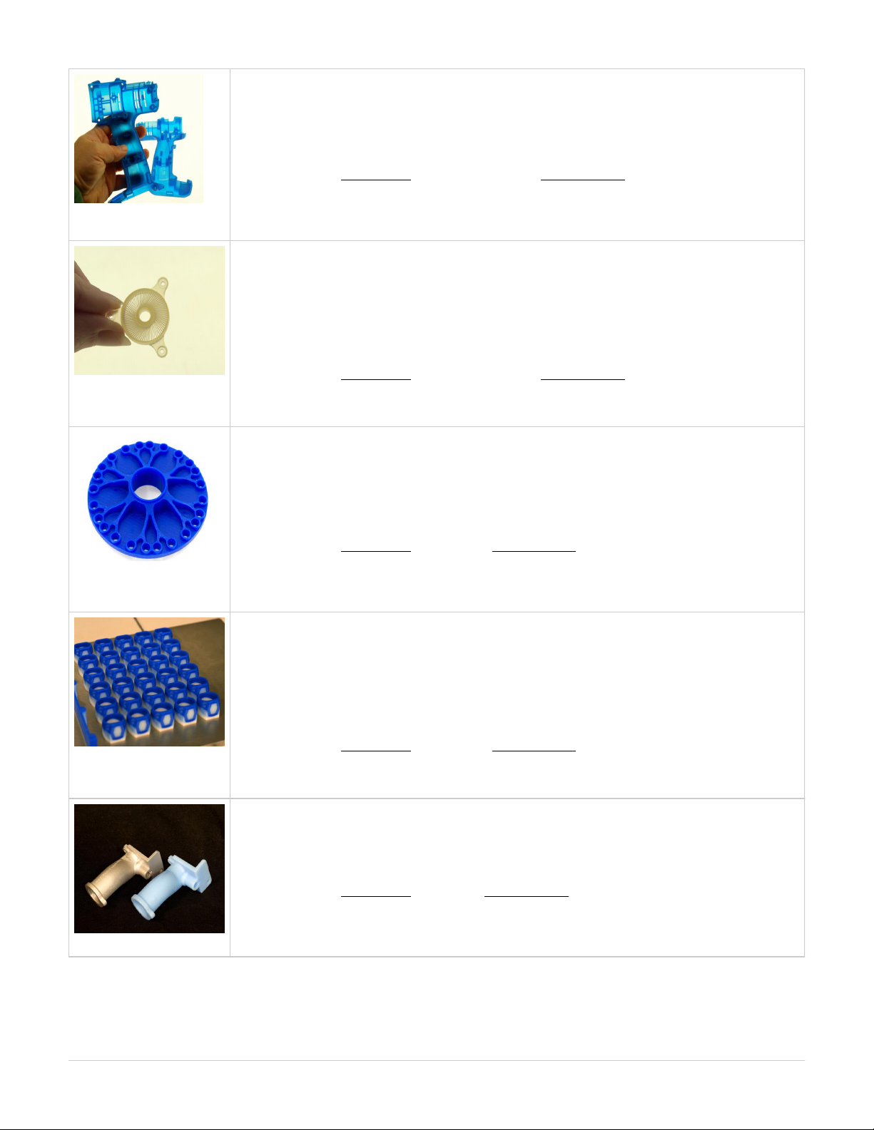
prints precision, durable plastic parts ideal for functional testing, design communication,ProJet™ HD3000
rapid manufacturing, rapid tooling and more. It features selectable resolution choices for speed and quality.
High Definition(HD), Ultra High Definition (UHD) Printing Mode:
: 298 x 185 x 203mm (11.75 x 7.3 x 8 inches); 127 x 178 xNet Build Volume (xyz): HD Mode UHD Mode:
152mm (5 x 7 x 6 inches)
: 328 x 328 x 606 DPI (xyz); 40µ layers; : 656 x 656 x 800 DPI (xyz); 32µResolution (xyz): *HD Mode UHD Mode
layers
: EX200, SR200, HR200; : S100 VisiJet® Materials: Part Materials Support Material
features part stacking and nesting capability in both build modes. The user canPart Stacking and Nesting:
now utilize the entire build volume by stacking parts vertically in the z-direction to fill up the entire build envelop
with parts. The user can control the space between layers to minimize support material usage and build time.
Now, hours can be saved by stacking parts and submitting single, long builds overnight and weekends.
ProJet™ HD3000plus features a 60% expanded high definition build envelope and advanced print detail
output. A new 16 micron print resolution delivers exceptional hard plastic parts with unmatched micro-detail and
surface quality.
High Definition (HD), Ultra High Definition (UHD), Xtreme High Definition (XHD) Printing Mode:
: 298 x 185 x 203mm (11.75 x 7.3 x 8 inches); : 203 x 178 xNet Build Volume (xyz): HD Mode UHD Mode
152mm (8 x 7 x 6 inches);
: 203 x 178 x 152mm (8 x 7 x 6 inches) XHD Mode
: 328 x 328 x 606 DPI; 40µ layers; : 656 x 656 x 800 DPI; 32µ layers; Resolution (xyz): HD Mode UHD Mode
: 656 x 656 x 1600 DPI ; 16µ layersXHD Mode
: EX200, SR200, HR200; : S100 VisiJet® Materials: Part Materials Support Material
Provides email notification to the user when their job begins, completes, aborts and if theEmail Notification:
system is low on material at any time during their build. Users can set their defaults and make changes as to
what emails they will receive via the Job Options window.
mass produces 100% wax patterns with unmatched surface quality, extreme fine detail andProJet™ CPX3000
exceptional precision. RealWax patterns are ideal for casting jewelry, apparel, micro-detail medical instruments
and devices, medical implants, electrical components, figurines, replicas, collectables and more.
High Definition(HD), Xtreme High Definition (XHD) Printing Mode:
298 x 185 x 203mm (11.75 x 7.3 x 8 inches); 127 x 178 xNet Build Volume (xyz): HD Mode: XHD Mode:
152mm (5 x 7 x 6 inches)
: 328 x 328 x 700 DPI (xyz); 36µ layers; : 656 x 656 x 1600 DPI (xyz);Resolution (xyz): *HD Mode XHD Mode
16µ layers
: CPX200 Wax; : S200 VisiJet® Materials: Part Materials Support Material
features part stacking and nesting capability in both build modes. The user canPart Stacking and Nesting:
now utilize the entire build volume by stacking parts vertically in the z-direction to fill up the entire build envelop
with parts. The user can control the space between layers to minimize support material usage and build time.
Now, hours can be saved by stacking parts and submitting single, long builds overnight and weekends.
ProJet™ CPX3000plus features a 60% expanded high definition build envelope with up to 20% increased print
speed. A new 20 micron high resolution option delivers exceptional wax patterns with smooth surface quality
and fine feature detail in less time.
High Definition (HD), Ultra High Definition (UHD), Xtreme High Definition (XHD) Printing Mode:
: 298 x 185 x 203 (11.75 x 7.3 x 8 inches); : 203 x 178 x 152mmNet Build Volume (xyz): HD Mode UHD Mode
(8 x 7 x 6 inches);
: 203 x 178 x 152mm (8 x 7 x 6 inches) XHD Mode
: 328 x 328 x 700 DPI (xyz); 36µ layers; : 656 x 656 x 1300 DPI; 20µResolution (xyz): HD Mode UHD Mode
layers; : 656 x 656 x 1600 DPI, 16µ layersXHD Mode
: CPX200 Wax; : S200 VisiJet® Materials: Part Materials Support Material
Provides email notification to the user when their job begins, completes, aborts and if theEmail Notification:
system is low on material at any time during their build. Users can set their defaults and make changes as to
what emails they will receive via the Job Options window.
ProJet™ CP3000 mass produces 100% wax patterns with smooth surface quality and exceptional precision,
supporting almost unlimited applications capabilities. RealWax patterns are ideal for general foundry casting
applications such as medium-sized to large mechanical parts for engines, pneumatics, aerospace, energy
production and delivery, custom manufacturing equipment, restorations and other heavy equipment.
298 x 185 x 203mm (11.75 x 7.3 x 8 inches)Net Build Volume (xyz):
328 x 328 x 700 DPI; 36µ layersResolution (xyz):
: CP200 Wax; : S200 VisiJet® Materials: Part Materials Support Material
features part stacking and nesting capability in both build modes. The user canPart Stacking and Nesting:
now utilize the entire build volume by stacking parts vertically in the z-direction to fill up the entire build envelop
with parts. The user can control the space between layers to minimize support material usage and build time.
Now, hours can be saved by stacking parts and submitting single, long builds overnight and weekends.
Page 8
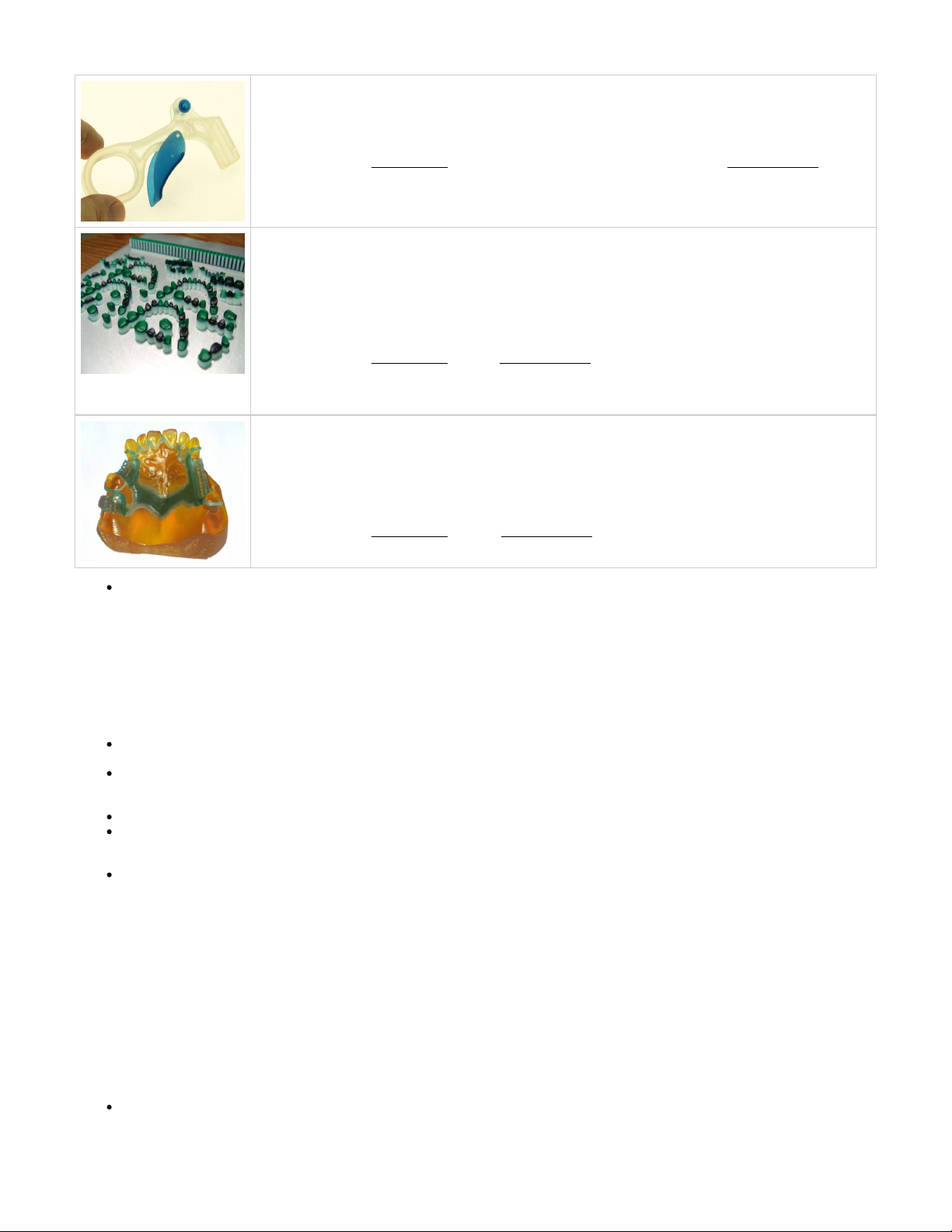
ProJet™ SD3000 prints high definition, durable plastic parts for engineering and mechanical design
applications including functional testing, form and fit verification, rapid prototyping, design communication, rapid
tooling and more.
298 x 185 x 203mm (11.75 x 7.3 x 8 inches)Net Build Volume (xyz):
328 x 328 x 606 DPI (xyz)Resolution (xyz):
: EX200 (natural) & SR200 (Blue, Natural & Gray); : S100VisiJet® Materials: Part Materials Support Material
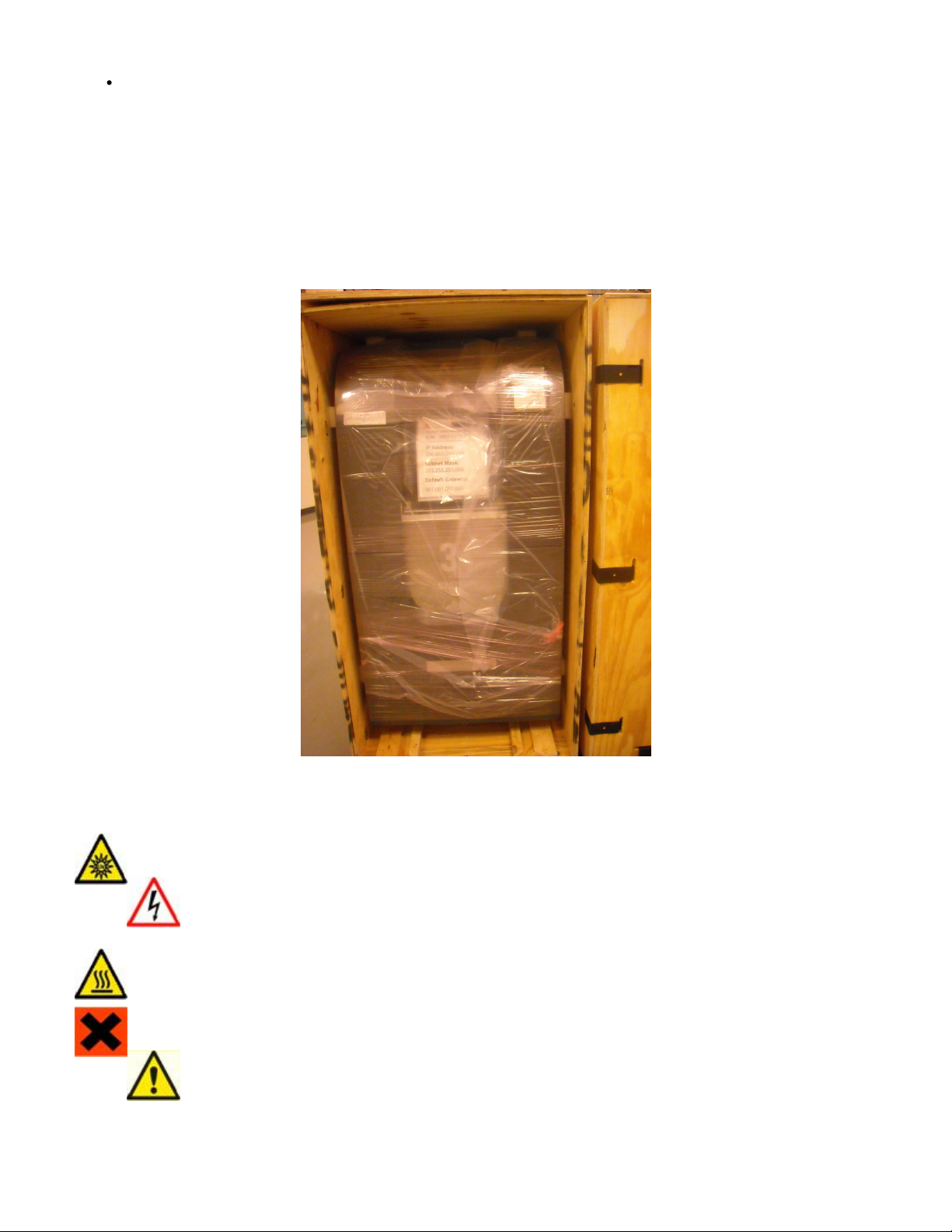
ProJet™ DP3000 accurately, consistently and economically manufactures precision wax-ups for dental
professionals. The system can generate hundreds of units each cycle. The wax-ups have a smooth surface
finish and can be cast or pressed with conventional techniques. The large build volume and optional part
stacking and nesting capabilities enable unattended operation ideal for high-volume production.
High Definition (HD); Ultra High Definition (UHD)Printing Mode:
298 x 185 x 203mm (11.75 x 7.3 x 8 inches); 203 x 178 xNet Build Volume (xyz): HD Mode: UHD Mode:
152mm (8 x 7 x 6 inches)
: 328 x 328 x 606 DPI; :328 x 328 x 606 DPIResolution (xyz): *HD Mode UHD Mode
: DP200; : S100 VisiJet® Materials: Part Materials Support Material
Provides email notification to the user when their job begins, completes, aborts and if theEmail Notification:
system is low on material at any time during their build. Users can set their defaults and make changes as to
what emails they will receive via the Job Options window.
ProJet™ MP3000 can produce any size model with smooth surfaces. Multiple models can be built at one time.
Works with any compatible intraoral, plaster or impression scanner. This Printing System is designed for use in
laboratories with extended unattended operation, same day processing - helps you reduce time and cost.
High Definition (HDX); Ultra High Definition (UHD)Printing Mode:
298 x 185 x 203mm (11.75 x 7.3 x 8 inches); 127 x 178 xNet Build Volume (xyz): HDX Mode: UHD Mode:
152mm (5 x 7 x 6 inches)
: 328 x 328 x 606 DPI; : 656 x 656 x 800 DPIResolution (xyz): *HDX Mode UHD Mode
: MP200; : S100VisiJet® Materials: Part Materials Support Material
1.5.1 Description and Definitions
1.5.1 Description and Definitions
Depending on the model of the ProJet 3000 3-D Production System, your system features different types of build styles to meet a variety of model
making applications. Please refer to Features and Benefits that will describe your extended choices for your particular system.
Description and Definitions
The High Definition (HD) Mode allows the user rapid model making capability on a full platform. This mode produces high quality parts
for concept models, verification designs and patterns for casting.
The Ultra High Definition (UHD) Mode allows the users to build extremely high resolution parts with exceptional surface finish and
superior accuracy. Models build in UHD mode are typically used for show models, fit testing and direct manufacturing using patterns for
investment casting of jewelry and small components.
Expanded UHD Mode: Provides the user with an Expanded Ultra High Definition (UHD) mode build envelope.
Expanded XHD Mode: Provides the user access to the new Extreme High Definition (XHD) Mode that features a new print resolution
with the same expanded build envelope available in UHD.
Email Notification: Provides email notification to the user when their job begins, completes, aborts and if the system is low on material
at any time during their build. Users can set their defaults and make changes as to what emails they will receive via the Job Options
window.
Part Stacking and Nesting
The new ProJet 3-D Production System, features part stacking and nesting capability in both build modes. The user can now utilize the entire
build volume by stacking parts vertically in the z-direction to fill up the entire build envelop with parts. The user can control the space between
layers to minimize support material usage and build time. Now, hours can be saved by stacking parts and submitting single, long builds overnight
and weekends.
Bounding Box Display Added to Print Preview
A few new features have been added to Print Preview to allow it to handle up to two gigabytes of part data on a single build.
The has been added to Print Preview to allow file sizes that were previously too large for Print Preview to loadBounding Box Display
successfully. The Bounding Box Display only displays the bounding extents of a given geometry and does not try to resolve the triangles
required to display an entire geometry. See .Section 8.1 Preview Build Job
Page 9
Job Submission Checking has also been added. Both the 3-D Modeling Client and Print Preview now check to make sure that the
maximum allowable accumulated build file size on the machine is not exceeded during job submission. The maximum threshold for job
submission is roughly two gigabytes or 40,000,000 triangles. See Section 8.3 Submit a Build Job
The new production system introduces new enhancements including an expanded build envelope for the UHDProJet™ HD 3000plus
build mode, the new XHD build mode and email notification.
1.7 Packaging
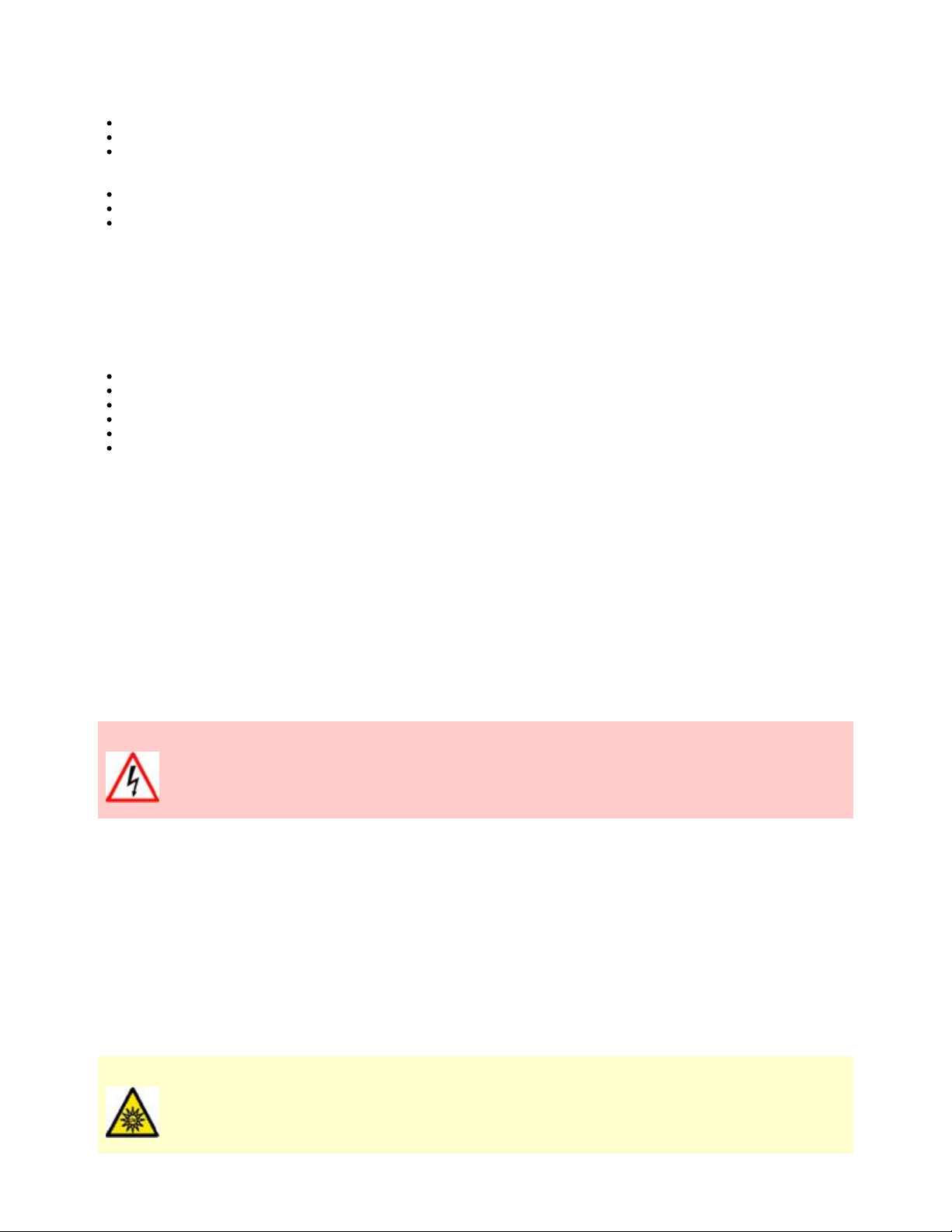
Packaging
damage or discard any packaging materials or carton(s). If the modeler needs to be returned to the manufacturer, it should be shipped inDo not
it's original packaging. If other packaging is used, the customer will be responsible for any shipping damages that may occur.
Only Certified/Qualifed Service Personnel can install the 3-D modeler.
02.0 Safety Symbols & Definitions
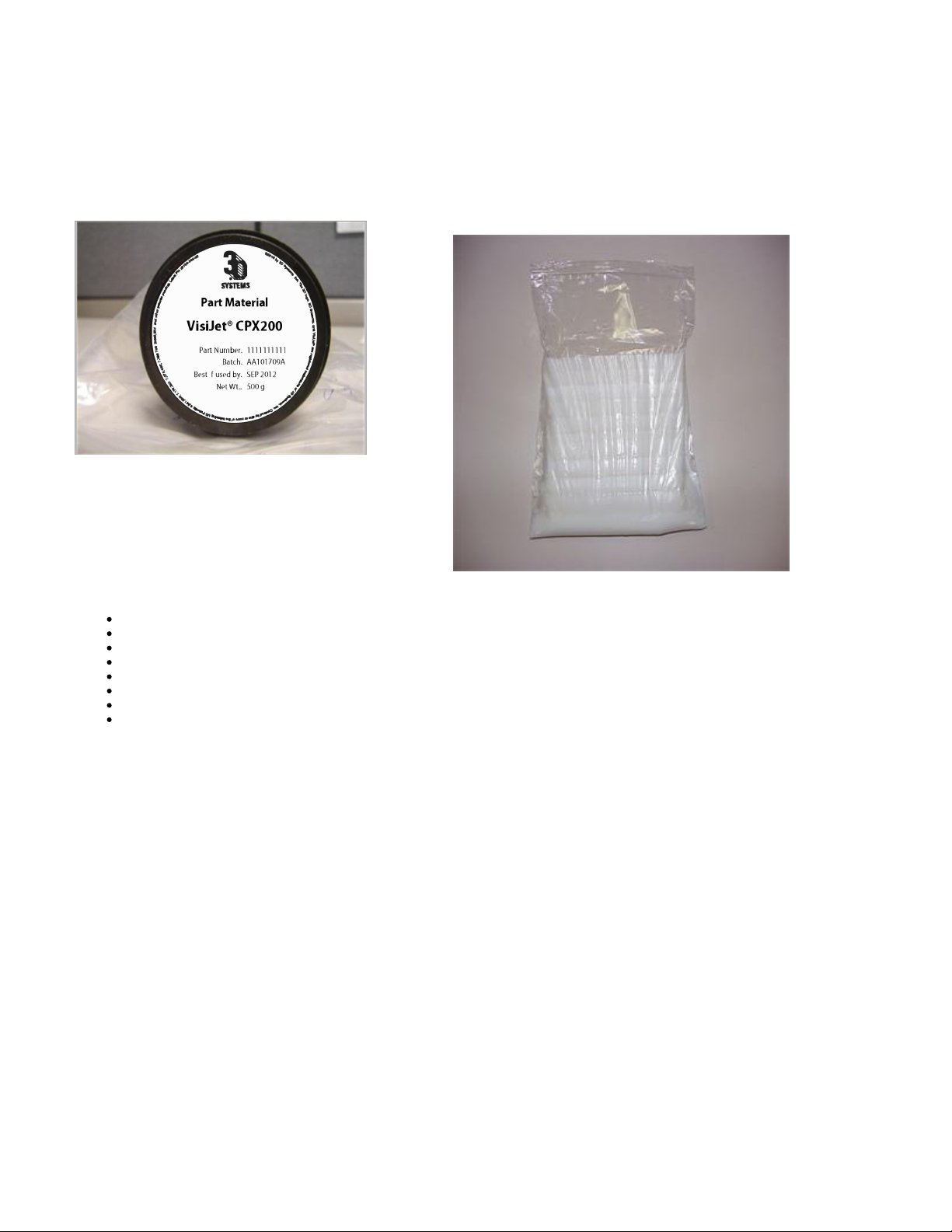
UV Radiation Hazard: Invisible UV radiation is accessible in the vicinity of this sign or behind the panel. Radiation can cause eye injury.
Access panels are for service only and should be opened only by certified service personnel.
High voltage electricity is accessible in the vicinity of this sign or behind the access panel. HighElectrical Shock Hazard:
voltage can cause severe burns or death. Access panels are for service only and should be opened only by certified service
personnel or trained maintenance personnel.
A hot surface is accessible in the vicinity of this sign or behind the access panel. Avoid contact. Hot surfaces canHot Surface Hazard:
cause severe burns. Access panels are for service only and should be opened only by certified service personnel or trained
maintenance personnel.
: Indicates that skin or eye irritation could result while exposed to aHarmful Irritant Warning
chemical composition.
Caution: Indicates something may happen that could cause loss of data, damage to equipment, or personal injury.
03.0 Safety Guidelines
Page 10
Before using the modeler, your company should have a safety program in place. The safety program should:
Label and point out hazardous equipment, materials, and procedures.
Explain what to do in case of an emergency.
Provide information about hazards of equipment and materials in the form of Material Safety Data Sheets (MSDSs). The MSDSs are
provided with all materials supplied by 3D Systems.
3.1 General
3.2 Electrical
3.3 Ultraviolet (UV) Light
3.1 General
The modeler is designed with built in safety features, improper use and malfunctions can cause injury to personnel. To prevent unsafe operation,
the modeler will automatically shut down if unsafe conditions are detected.
Follow these safety guidelines when operating the modeler:
Read and follow all modeler instructions.
Follow all safety rules and heed all cautions and warnings in this guide.
Do not attempt to open chamber door while build in progress.
Do not use any material without reviewing the Material Safety Data Sheets (MSDS).
Dress power and communication cables behind modeler to prevent tripping.
Do not attempt to access, service, or adjust modeler components. Do not attempt to perform any maintenance procedures unless
specifically trained to do so.
Operators are trained to operate system and perform all necessary tasks to create a part.
Certified service personnel are those who completed the 3D Systems service training package and certified to perform service tasks. Certification
may occur at different levels, and service providers should only perform tasks they are authorized and certified to complete.
Do not ignore warning signs posted during modeler service operations.
If an error message appears on the modeler's LCD refer to Section within this guide before resuming operation.10.0 Error Messages
To prevent potential skin-irritation and sensitization due to contact with waste material, follow all guidelines within .Build Material Safety
To prevent pinch and crush injuries to the hand, use caution when replacing platform inside the build chamber.
3.2 Electrical
DANGER
Hazardous voltage exists inside the modeler. Injury or death from electrical shock can result if you remove the printer's
external panels. Panels should only be removed for service by trained and certified 3D Systems Technical Support
personnel.
To prevent electrical shock, the modeler will not operate unless external panels are installed. service rating Verify facility's electrical before you
connect power to the modeler.
3.3 Ultraviolet (UV) Light
CAUTION
Hazardous UV radiation exists inside the modeler build chamber during build job. Eye injury or blindness can result if
chamber door is opened while a build job is in progress. If a build job is running, abort build job before attempting to open
chamber door.
Page 11
To prevent eye injury, ultraviolet (UV) light inside the chamber will not operate when chamber door is open. When closed, the chamber door
keeps UV radiation from escaping. The chamber door remains locked if build job is paused.
04.0 Build Material Safety
Users of the modeler should be informed of potential hazards of part material prior to working with a modeler, or performing duties which may
result in exposure to uncured part material, such as removal and disposal of bin liners and empty cartridges, or waste bag.
4.1 Disposal
4.2 Health Hazards
4.3 Material Handling
4.4 Personal Protection Equipment
4.5 Regulatory Information
4.6 Spilled VisiJet® Material
4.7 Waste Removal
4.8 Material Storage
4.1 Disposal
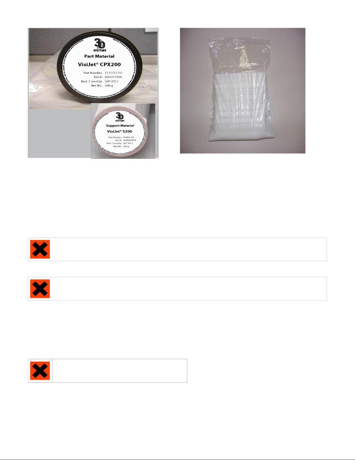
Disposal of parts produced are not subject to regulations of any known agency worldwide. VisiJet® support material and cartridgesfully cured
may be disposed of in ordinary office trash.
Uncured part material waste is classified as regulated, and in some areas hazardous, requiring special packaging, transportation, and disposal.
The disposal of partially cured or uncured model material must comply with all local, state, and federal environmental safety regulations.
Applicable part "waste" includes cartridges (empty or full) and waste bag. Any materials used cleaning up uncured part material should be
disposed of as uncured part material.
Page 12
To find out facility disposal requirements, contact a local waste disposal provider. (Local environmental regulatory agency should have a list of
qualified providers.) You will need to give disposal service provider a copy of the part material MSDS / SDS, and possibly other forms included in
the Appendix of your , such as Waste Profile Worksheet and SNUR (Significant New Use Regulation - U.S.VisiJet® Material Handling Guide
only). A report will be provided, indicating disposal requirements, as well as a quotation for regularly scheduled pickups. If assistance lis needed
locating a waste disposal provider, or completing a waste disposal form, contact local 3D Systems Hotline.Technical Support
3D Systems assumes no liability or responsibility for proper disposal of uncured part material. Proper disposal of uncured part material is the sole
responsibility of the user.
4.2 Health Hazards
Health Hazards
Uncured VisiJet® model material is a sensitizer. Skin or eye irritation could occur when exposed to the chemical composition of the
material.
Any chemical may exert harmful effects if contacts or enters the body. VisiJet® part material is a sensitizer and irritant.
Skin Sensitization
CAUTION: Uncured VisiJet® part material is a sensitizer. Skin or eye irritation could occur when exposed to the chemical composition
of the material.
Uncured material is a sensitizer, and can cause allergic reactions if contacts skin without protective gloves. Refer to personal protection
for more information. To avoid sensitization, do not allow uncured material to contact skin. Consult the MSDS for specific informationequipment
about the sensitization potential.
Inhalation
Under normal operation, inhalation is not an expected route of entry.
Ingestion
CAUTION: Uncured VisiJet® model material is toxic if ingested.
Uncured material is toxic if ingested. Uncured material must not be present where food and drink are stored, prepared, or consumed and not
ingested. After handling modeler materials, wash hands with soap and water before consuming or preparing food.
Handling Finished Parts
Finished (cured) parts can be handled or disposed of the same as standard household plastic products. VisiJet® parts are not recyclable. VisiJet®
materials are not intended for, and cannot be used for medical implant, or food or drink handling applications.
Page 13
Exposure control
The modeler has a variety of built-in engineering controls which are designed to prevent operator exposure. Do not try to change or disable these
controls.
Appropriate hygienic practices should be followed, including washing with soap and water before meals, breaks, smoking, applying cosmetics,
using toilet facilities, and after work.
Employees should be alerted to the need to clean and rinse off any contacted surface promptly in order to prevent
further contamination. Ensure a convenient washroom location is provided with access to soap, water, and
disposable paper towels.
4.3 Material Handling
Emergency (MSDS)
Chemtrec USA ; Europe (800) 424-9300 +1-703-527-3887
Packaging Inspection
VisiJet® material is packaged in cartridges. Eight cartridges are packaged in polybags, and placed in shipping
cartons. Upon receipt of material shipments, inspect cardboard carton exterior for signs of damage and leakage. If leakage is observed, DO
NOT open carton, and contact 3D Systems' Hotline. If no leakage is observed, store materials in cartons until material is used. Technical Support
Part Building
If uncured material is observed on the part or platform after build, this is an abnormal condition, and is an indication the modeler requires servicing
by 3D Systems. Assume any liquid or paste-like material is part material. Do not directly touch uncured part material without protective gloves.
Discontinue use of the modeler, pending service by a 3D Systems Technical Support Representative.
Flammability and Combustibility
Do not expose materials to heat at or above 230°F (110°C), flames, sparks, or any source of ignition. (Though the U.S. Department of
Transportation does not consider VisiJet materials a "flammability hazard," they do classify them "combustible" based on flash points.) For more
information on VisiJet material flash points and combustibility, see VisiJet® Material Handling and Post Processing Guide.
4.4 Personal Protection Equipment
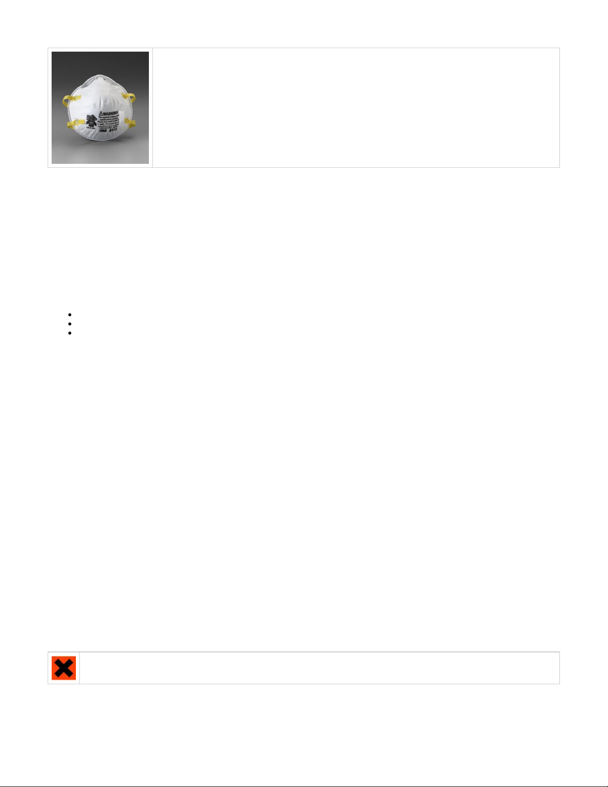
Exposure to uncured model material may occur; when removing and disposing of the bin liners containing spent
model material cartridges and waste bag. To prevent contact, wear chemically resistant protective gloves - nitrile
or neoprene gloves are recommended. Do not use Latex gloves.
In the event of a leak or spill of uncured part material, wear safety glasses with side shields to provide eye
protection
Page 14
Because of the modeler's built in engineering controls, respiratory protection is not necessary during normal
operation. A NIOSH-approved (or equivalent) dust mask is recommended when dry sanding cured material parts.
4.5 Regulatory Information
Support material has no known regulatory requirements.
In the U.S., material is subject to special EPA disposal regulations and record-keeping requirements. "Uncured VisiJet® material"uncured
includes any model material cartridge (empty or full), and waste bag---about half of which is uncured model material. For complete disposal
regulation details, see Appendix in your Material Handling Guide.
In the U.S., you must keep the following disposal records for five years after the date of disposal:
The quantity of model material received (new or "virgin").
The name and address of the shipping location (the "responsible party" - generally your waste disposal service provider).
The quantity of model material shipped (disposed). For further information, see your .Material Handling Guide
For assistance, contact 3D Systems .Technical Support
4.6 Spilled VisiJet® Material
Spills of material are HIGHLY UNLIKELY, and should NOT occur in normal operation of the modeler. If a leak occurs, it is an indication of a
serious modeler malfunction.
The first priority is to protect users from inadvertently touching material. Spills of support material can be cleaned without use of protective gear,
and disposed of as office trash. Handling uncured part material requires use of gloves and other to ensure nopersonnel protective equipment
direct contact with uncured model material. If you don't know which material it is, assume it to be uncured model material, and handle accordingly
- with the recommended personal protective equipment.
Promptly remove spilled material, dispose of waste material, and cleanup materials per local regulatory requirements. Discontinue use of the
modeler, and contact 3D Systems for a service visit to determine and repair the source of leakage. Technical Support
Small spills of uncured liquid part material can be cleaned up using disposable towels, non-reusable rags, or absorbing materials such as
sawdust, clay, diatomaceous earth, or activated charcoal. If spilled material is hot (liquid), wait until cools and gels before wiping up. After wiping
up the spill, wipe surface with denatured or isopropyl alcohol and clean thoroughly with soap and water.
Consider avoiding placement of the modeler over carpeting, or consider use of barriers to avoid the possibility of carpet damage if spills were to
occur.
Advise service provider involved, of the spilled material, and provide MSDS and other material information prior to contact with the material.
Advise them of disposal requirements for model material and clean-up products if model material (uncured) is the spilled material. Use of heat
above 65°C (149°F) may prove helpful in removing spilled model material from carpet.
Tools contaminated with model material should be cleaned prior to reuse. Solvents such as denatured alcohol or Iso-Propyl Alcohol (IPA), are
normally required to clean equipment and tools. Wash with soap and water to remove any traces of excess model material or solvent. Contact
solvent suppliers for information on proper handling of solvents if used for clean-up.
4.7 Waste Removal
CAUTION: Uncured model material is a sensitizer. Skin or eye irritation could occur when exposed to the chemical composition of the
material.
Wear protective gloves before removing any waste product from the modeler. Be careful not to spill, drop, or expose others to these materials -
particularly part material cartridges or waste bag. Dispose of all waste material appropriately per local regulatory requirements.
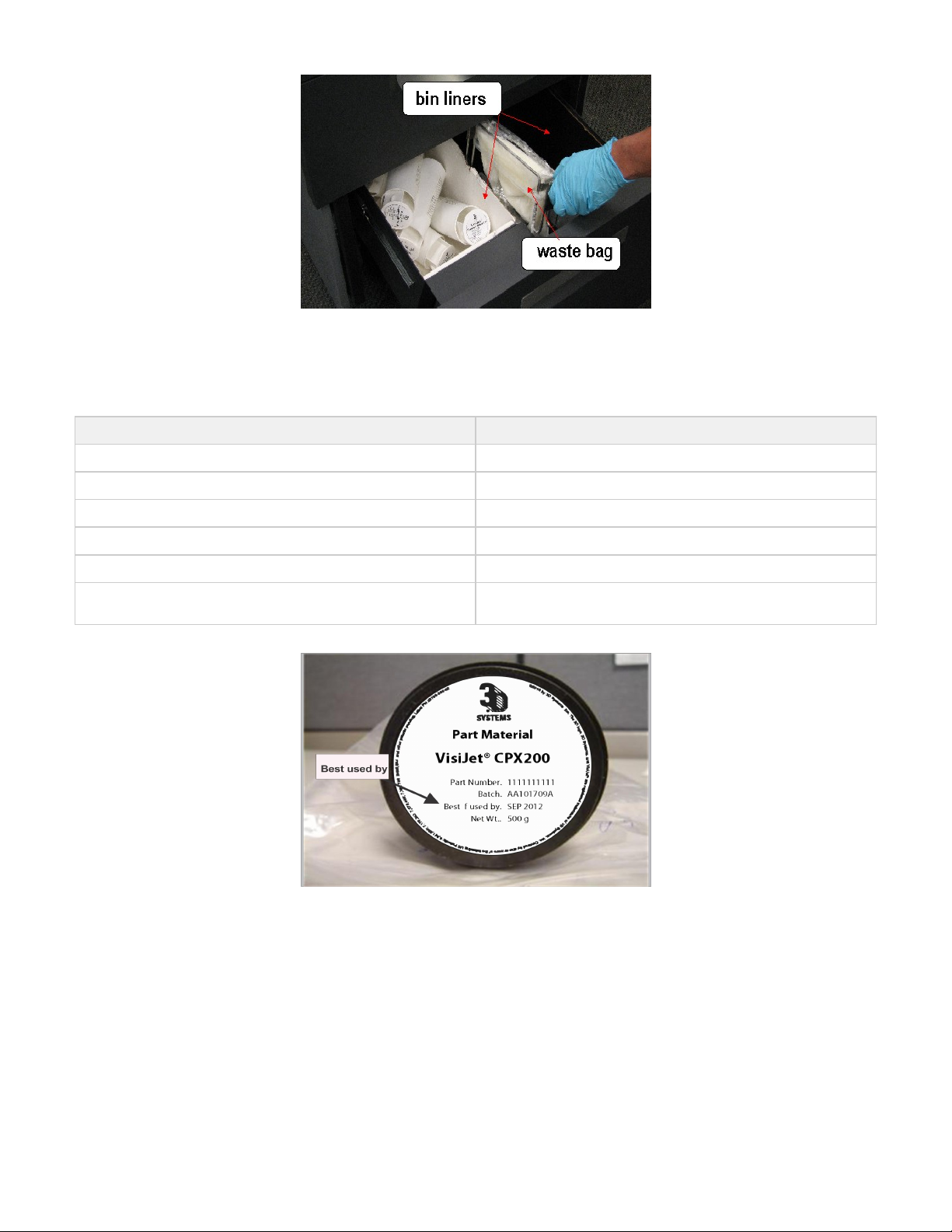
Remove support and modeling cartridges from the waste bins. if liners are contaminated with uncured modeling material, replace the liners.
Dispose of waste bag containing both support and uncured model material. Replace with new waste bag.
Page 15
4.8 Material Storage
BUILD MATERIAL SUPPORT MATERIAL
Shelf life for HR200, SR200,MP200, DP200- 2 yr Shelf life for S100- 5 yr
Shelf Life for CP200, CPX200- 5 yr Shelf Life for S200- 5 yr
Climate - Cool, dry area with adequate ventilation Climate - Cool, dry area with adequate ventilation
Temperature Range - 60°F (16°C) to 80°F (27°C) Temperature Range- 60°F (16°C)to 80°F (27°C)
Maximum Storage Temp - 95°F (35°C) Maximum Storage Temp - 95°F (35°C)
Environmental Conditions - No direct sunlight, heat, flames, or UV
energy.
Environmental Conditions - No direct sunlight, heat, flames, or UV
energy.
NOTE: For optimal results, keep stored cartons closed and sealed, and do not open polybags until cartridge is ready for use.
Always check material "Best used by" date before loading cartridge. Do not load cartridges into modeler if about to expire. When modeler detects
an expired cartridge, it aborts the build and ejects the cartridge if date is past expiration date for support material or more than one year past the
expiration date for model material.
Page 16
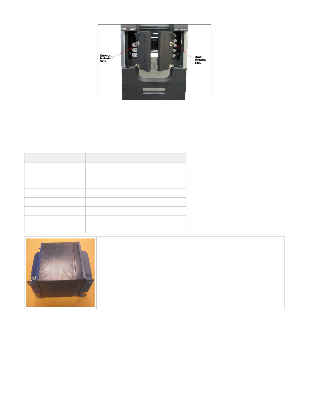
Support ( ) cartridges must be loaded in the left side feed slot. VisiJet part ( ) cartridges must be loaded in the side feed slot.white black right
Before removing a cartridge from protective polybag and before loading into modeler, inspect the cartridge for signs of damage or leakage. Do not
load a damaged or leaking cartridge. Dispose of it according to local regulations.
05.0 System Requirements
Power Rating
Country Voltage Frequency Amps (A) Phase Power Cord
USA 100-127 VAC 60 Hz 15 A 1 P/N 23417-802-XX
France 200-240 VAC 50 Hz 15 A 1 P/N 23417-802-XX
Germany 200-240 VAC 50 Hz 15 A 1 P/N 23417-802-XX
Hong Kong 200-240 VAC 50 Hz 15 A 1 P/N 23417-802-XX
Italy 200-240 VAC 50 Hz 15 A 1 P/N 23417-802-XX
Japan 100-127 VAC 60 Hz 15 A 1 P/N 23417-802-XX
Switzerland 200-240 VAC 50 Hz 15 A 1 P/N 23417-802-XX
United Kingdom 200-240 VAC 50 Hz 15 A 1 P/N 23417-802-XX
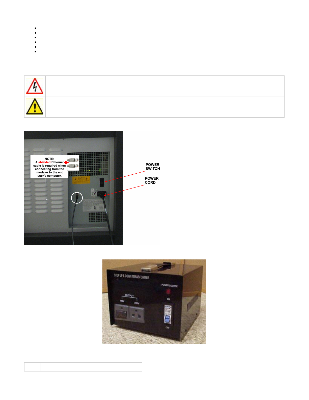
If connecting the modeler to a 200-240 VAC facility power outlet, connect the power cord (located
inside modeler's country kit)to the external transformer. Connect the transformer's power supply to the
facility's outlet.
06.0 Familiarization
The 3-D modeler system is a Multi-Jet-Modeling (MJM) line of modelers. The solid imaging modeler produces plastic prototype models from 3D
solid Computer-Aided Design (CAD) models and through the modeler client software. The models are generated in a rapid prototyping (RP)
environment. The primary features of the 3-D modeler are the user interface, build chamber, material feed slots, and waste material drawer. The
back of the modeler houses the power switch, internet and the power cord connections.
Page 17
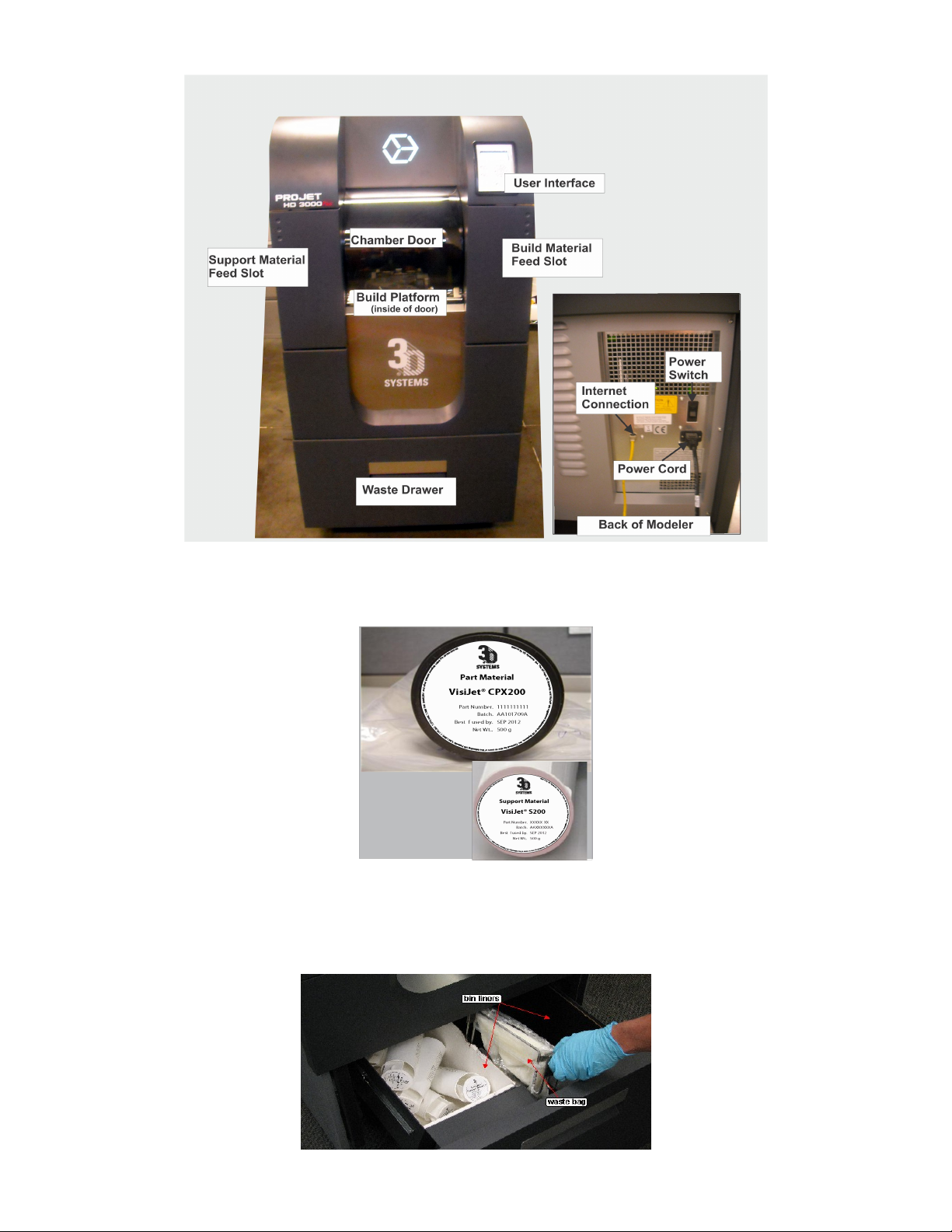
The three dimensional solid models built by the modeler consist of two materials (support material and part material). The support material is a
wax based material providing adhesion to build platform, as well as, providing material used to produce supports required to build the model.
The part material used to build the models is an ultraviolet (UV) curable material. After a layer of material is deposited in the build chamber, the
part is exposed to a UV flashlamp. The UV energy is absorbed by the material converting a liquid model material to a solid polymer. When the
build is complete the model (consisting of the two materials) is adhered to the build platform by means of the support material.
The material delivery system consists of two vertical stacks referred to as "magazines." The magazine on the left side of the machine holds nine
support material (white) cartridges. The right side of the machine holds up to nine part material (black) cartridges. The magazine system feeds
the cartridges to the modeler using a clamp feed system. As the cartridges are emptied, the clamp feed system releases the empty cartridge(s)
into the waste drawer. Material waste is generated by two processes; cleaning the printhead array plate and planarization. The cleaning process
involves purging jets and wiping the printhead array plate. Gravity pulls the waste material from the Head Maintenance Station (HMS) trough into
the waste umbilical. The combined waste material is then purged. The printhead cleaning process is invoked automatically prior to test print and
build jobs.
Page 18
After the build is complete, the platform and the model is then removed from the modeler. A secondary operation, knows as finishing, is required
to provide a finished/cleaned model. Refer to your ProJet™ Finisher's Guide for more information.
6.1 System Functions
. Menu names and menu options are capitalized in boldface text. Instructions for selecting menu options look like this: "Select Menus:
." This means "select (click or highlight) the , then select on the menu." Menu>Option Menu Option
Keys: Keyboard key names are capitalized; for example, "Press the Enter key."
Buttons: Command buttons on the modeler's user interface are in boldface upper case text; for example, "Press the button." TheONLINE
command buttons are: , , , , , , and . MENU LIGHT PAUSE ONLINE YES NO ABORT
Display Text: Text on the modeler's display appears in uppercase in this guide; for example, "When the display shows ? , pressPAUSE JOB Y/N
."YES
07.0 Modeler Setup
To prepare and build part files, connect your PC and modeler to the network. For additional information refer to Facility Requirements Guide.
Component Type Software Requirements
PC Microsoft ® Windows® 98, Millennium Edition (Me), New Technology (NT) 4 (SP 3+), 2000, or XP.
Page 19
7.1 Power on Modeler
7.2 Add Cartridge and Install Build Platform
7.3 Install and Run ProJet™ 3-D Modeling Client Software
7.4 Create STL File(s) to Build
7.5 Submit Test Build
7.6 Build Demo
7.1 Power on Modeler
WARNING: Read and follow safety guidelines in Ignoring these guidelines could result in death, bodily injury, orElectrical Safety.
modeler damage due to electrical shock or fire.
CAUTION: Verify modeler's rear panel power switch is OFF. Connecting power with switch on can damage modeler and cause
bodily injury or death due to sudden, unexpected mechanical motion.
1. Plug modeler power cord P/N 23417-802-XX into modeler's rear panel socket. Plug modeler power cord into a grounded power outlet.
2. If 200-240 VAC required, connect modeler power cord to external transformer in kit P/N 23418-801-XX, then plug transformer power cord into
a grounded power outlet.
3. Place switch on the rear of modeler to the ON position.
4. Wait 4 hours for modeler to warm up before pressing to start a build job.ONLINE
NOTE: You can submit jobs to modeler while it is warming up.
Page 20
1.
2.
3.
7.2 Add Cartridge and Install Build Platform
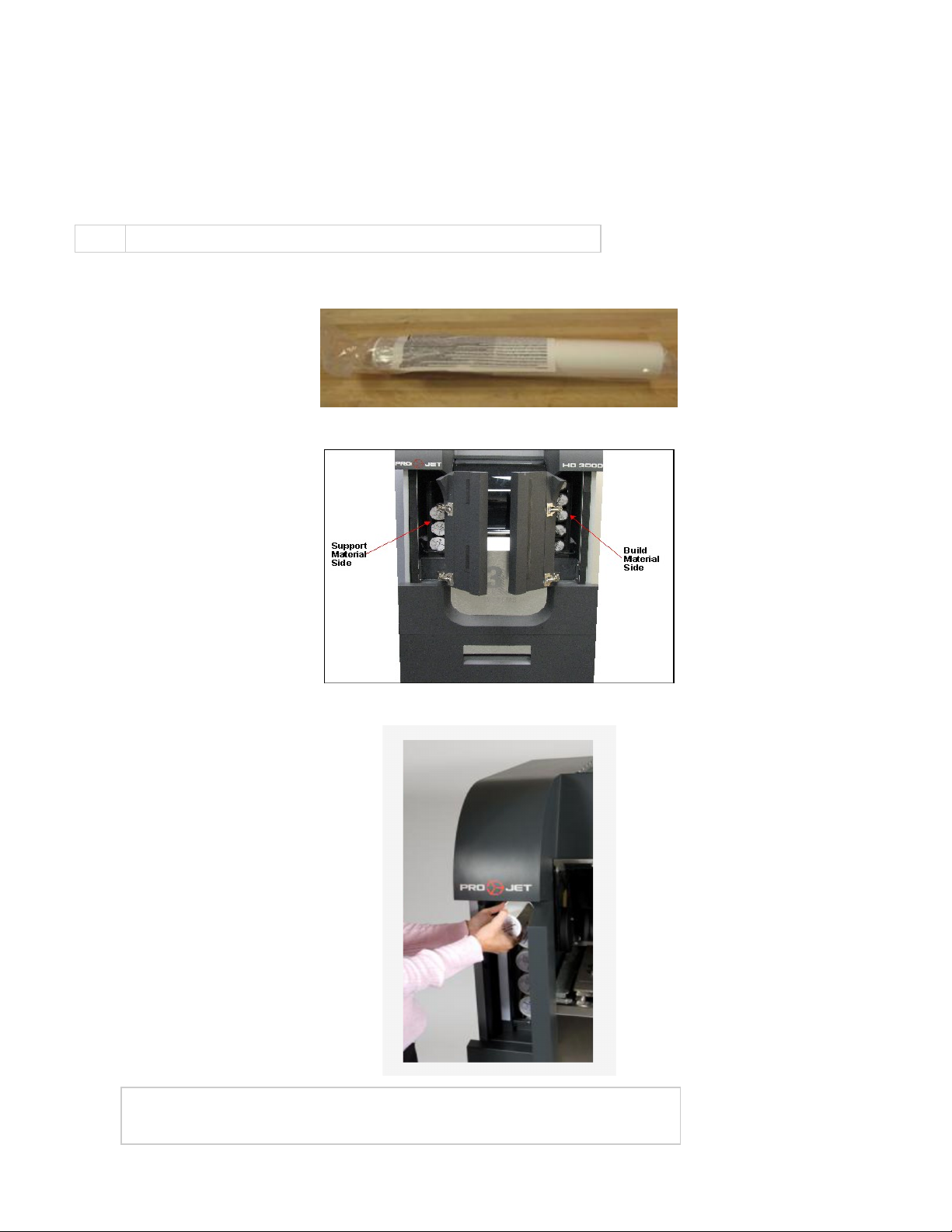
Add Cartridge
Add material to feed slot when it has 3 cartridges or less. When a feed slot has 3 cartridges or less,
the operator panel displays and/or . Add 9 cartridges maximum per slot. ADD SUPPORT ADD PART
5 cartridges are visible when magazine feed slot is full.
NOTE: Before handling build material cartridges. Read Material Safety Data Sheet (MSDS).
Unpack cartridge and MSDS/SDS Sheet. Remove cartridge's from poly bag.
Open left and/or right magazine feed slot doors. Insert support material (white)
cartridges in left magazine feed slot. Insert model marterial (black) cartridges
in right magazine feed slot.
Lower each cartridge into slot. Ensure flat of cartridge and label on cartridge
is facing upward. Add eight cartridges maximum to each slot.
Close both magazine feed doors.
NOTE: For proper operation of the feed system, a minimum of three (3) support and three (3)
build cartridges must be present.
Page 21
4.
5.
6.
7.
8.
1.
2.
3.
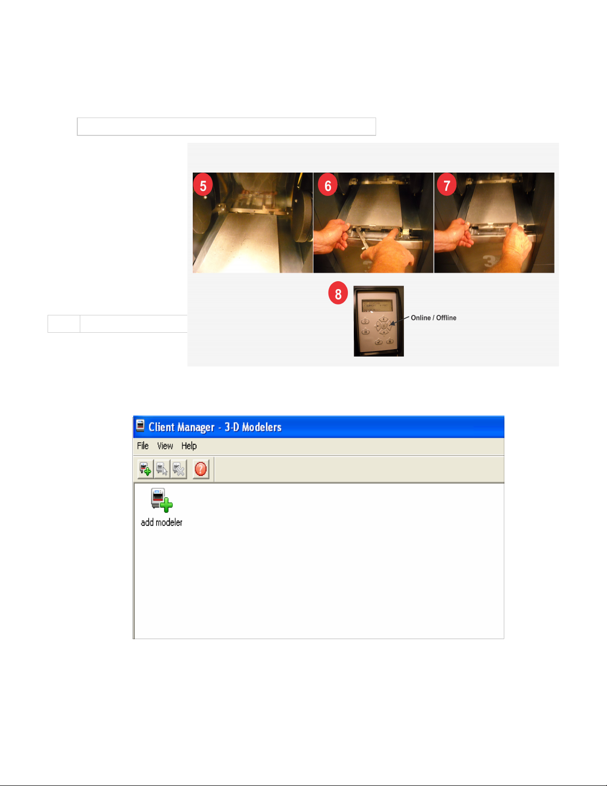
Install Build Platform
NOTE: Clean platform using Isopropyl Alcohol before installing into modeler.
Open the chamber door.
Align platform's rear notch into
x-carriage's locating tab.
Align platform's front notch into
latch's front locating tab.
Press locking tab into the
notch to secure.
Close the chamber door and
press ONLINE.
7.3 Install and Run ProJet™ 3-D Modeling Client Software
NOTE: Before installing software, ensure network and PC meet requirements.Modeler Setup
Load the 3-D Modeling Client
from CD packagedSoftware
with the modeler accessories
kit. An autorun file on the CD will automatically load when CD is inserted into ROM drive of the computer. If installation program does
not start when loaded, select and run from the root directory of the ROM drive.Setup.exe
After successfully installing software, select from the menu and then select > icon. The modelerStart Program 3-D Modeling Client
window appears.
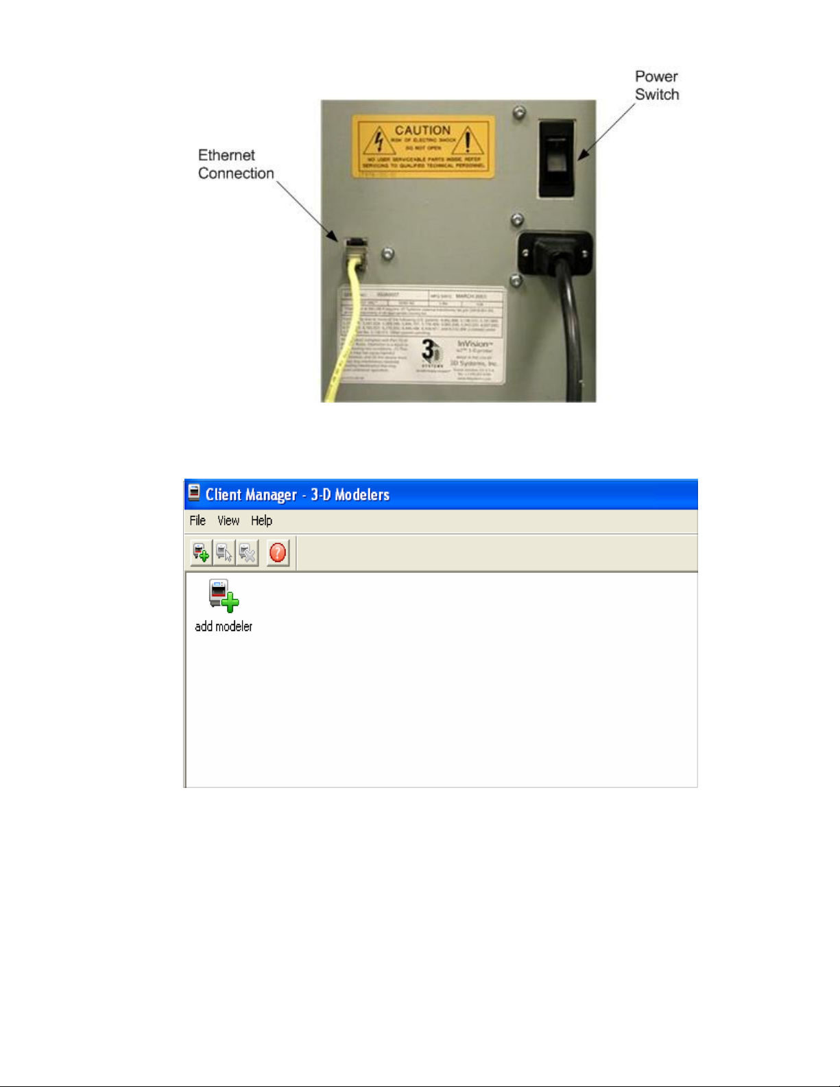
Power up modeler as described in . Establish a network connection between modeler and PC. 7.1 Power on Modeler
Page 22
3.
4.
5.
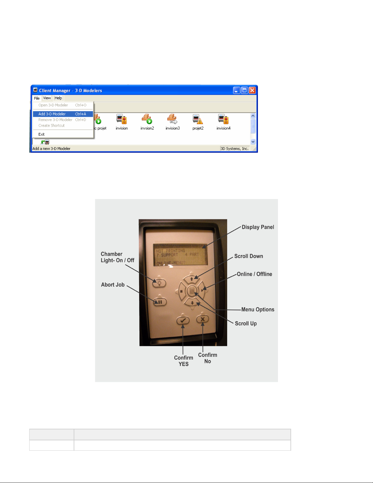
You can only submit build jobs to modelers having icons in the window. To create an icon for a modeler, click icon (orAdd modeler
choose ), the Add Modeler window appears, prompting to choose the modeler's IP address from list of availableFile > Add 3-D modeler
modelers.
Select the IP address for desired modeler, click OK. The client software prompts for a modeler name. After entering a name, an icon for
the modeler appears in the 3-D Modelers window. Once an icon for a modeler exists, click it to add files for a build job, preview a build
job, sumit a build job, or manage a build job in progress.
Page 23
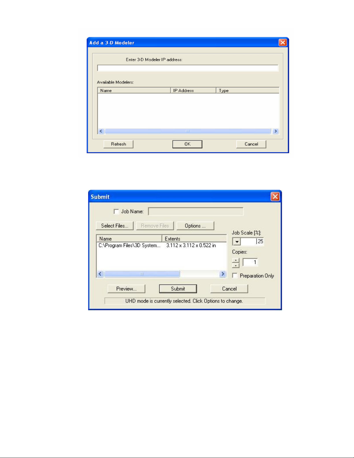
6. After the modeler is added, click on the icon in the 3-D modeler window or choose to submit build jobs to theFile > Open 3-D modeler
modeler, or manage build jobs in it's queue. If the modeler icon has a red lightning bolt, your PC is not communicating with the
modeler. Jobs cannot be submitted to the modeler until communication is restored.
7.4 Create STL File(s) to Build
The modeler builds 3-D models from files using industry-standard ( ereo ithography) format. Most popular 3-D modeling CAD software.STL ST L
packages can save files in STL format. Sample STL files are in the \3-D Modeling Client\Samples folder.
Page 24
7.5 Submit Test Build
It is recommended to submit a Test Build prior to each build job to ensure part quality.
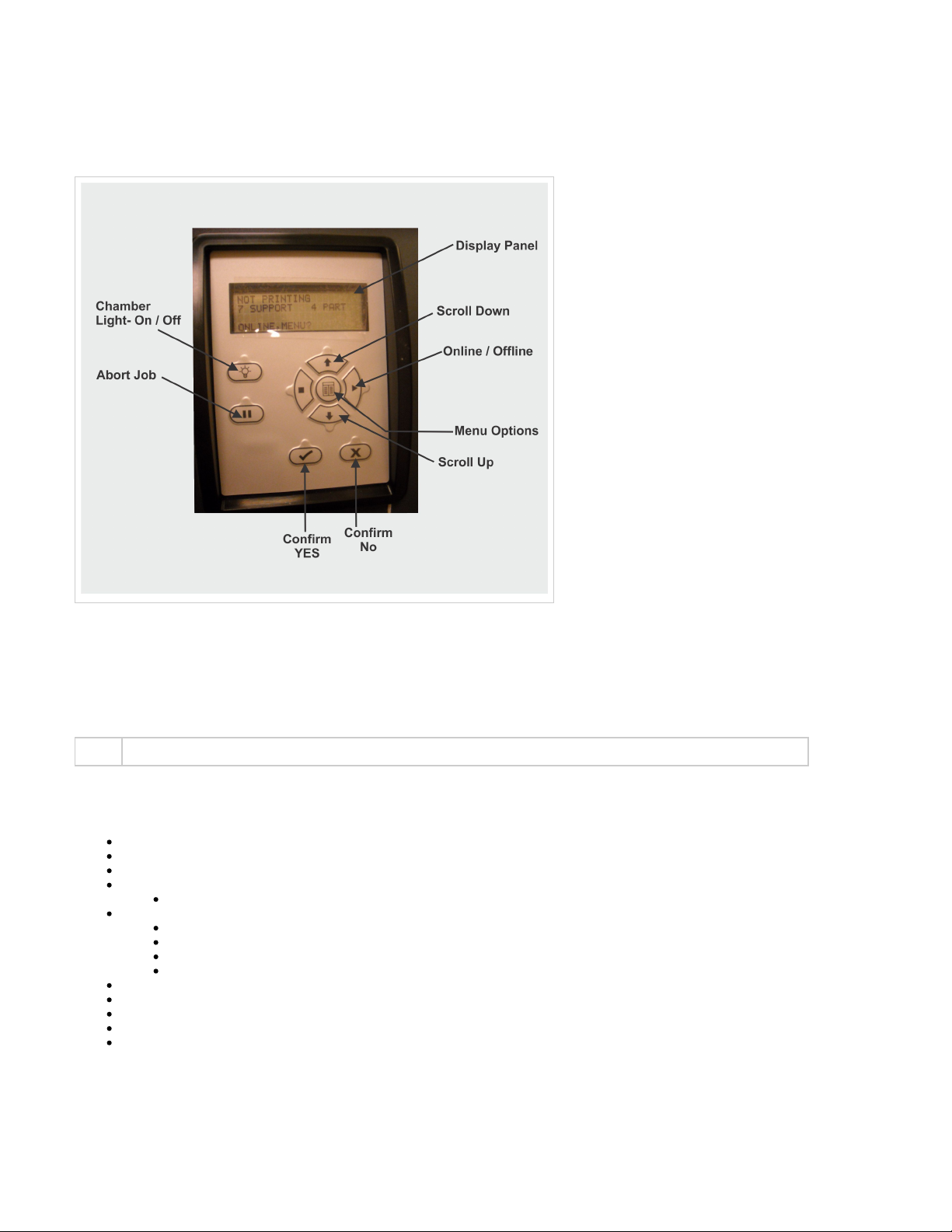
Press , scroll to highlight .MENU TEST BUILD
Press . The message scrolls across the display. # Press if the platform is clear and theYES PLATFORM CLEAR DOOR CLOSED? Y/N YES
door is closed, otherwise press .NO
Page 25
1.
2.
7.6 Build Demo
Press , scroll to highlight . # Press on Operators panel; the system displays .MENU BUILD DEMO YES PLATFORM CLEAR? Y/N
When platform is clear, press . The modeler starts demo build job.YES
08.0 Operations
This section provides information on Previewing, Saving, Submitting, and Managing modeling jobs through the modeler's operator panel menu
and 3-D Modeling Client Software. In addition this section describes how to remove the build platform, how to empty the waste drawer and how
to shut down the modeler.
NOTE
Make certain the modeler is during the job submittal process. Place the modeler on-line after the job is submitted.Off-Line
8.10 Shrink Compensation for ProJet VisiJet® Materials
8.1 Preview Build Job
8.2 Save a Build Job
8.3 Submit a Build Job
8.3.1 Remove Build Platform
8.4 Manage Build Jobs
8.4.1 Delete Build Jobs
8.4.2 Pause Build Job
8.4.3 Abort Build Job
8.4.4 Repeat Build Job
8.5 Modeler Status
8.6 Empty Waste Drawer
8.7 Shutdown Modeler
8.8 Remove Part from Build Platform
8.9 3D Modeling Batch Submission for Production Environment
8.1 Preview Build Job
Preview Screen Icon Description
Page 26
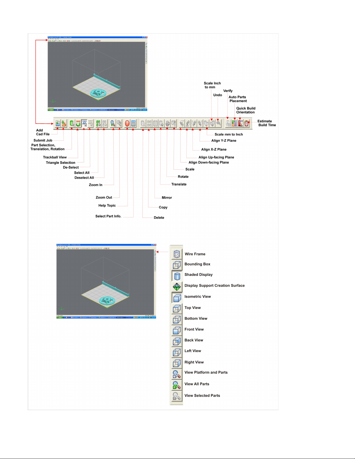
Preview build job before submitting.
Page 27
1.
2.
3.
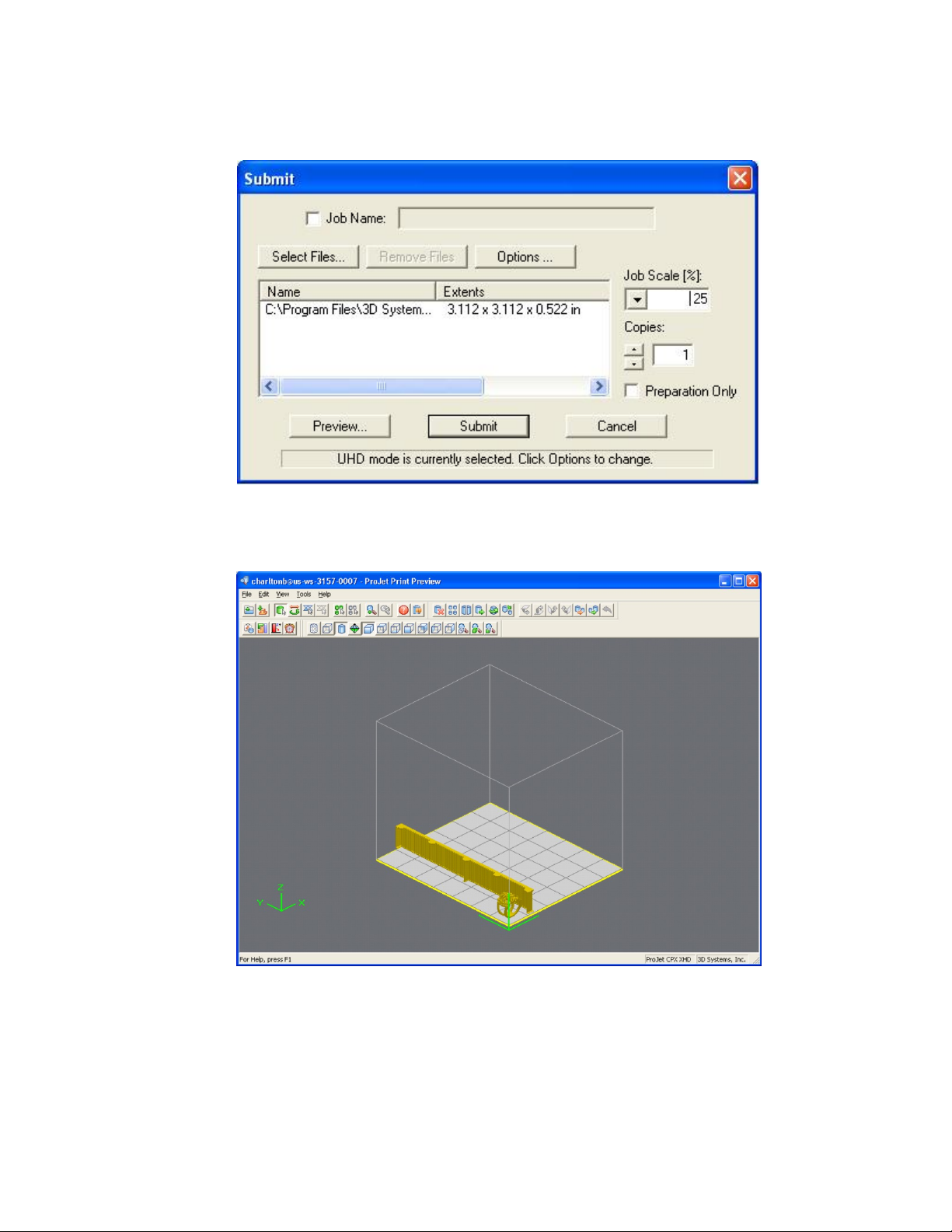
Preview jobs before submitting them to the modeler.
Click the button on the Client's Submit dialog box. At least one part must be added for build in the Submit dialog box before youPreview
are able to preview.
Highlight a Job Name in modeler's Info window, click the button or choose . The print preview window will openPreview Job > Preview
as shown below.
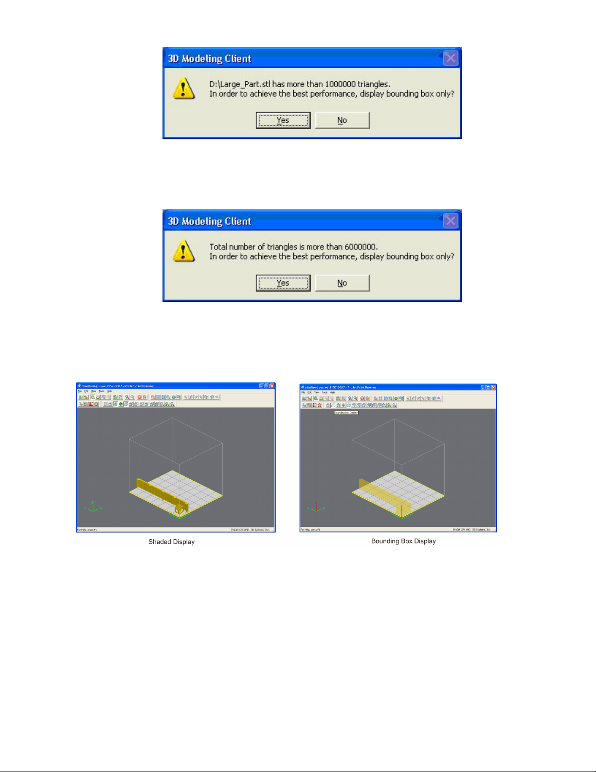
If the file you are trying to preview is beyond the threshold of a certain file size, the system will display one of the following two messages.
This message is displayed if the file size of the individual part is larger than 100 MB, (1,000,000 triangles).
Page 28
3.
This message is displayed if the accumulated file size of multiple parts exceeds 300 MB, (6,000,000 triangles).
If you click , the system will automatically switch to the . The only displays theYes Bounding Box Display Bounding Box Display
bounding extents of a given geometry and does not try to resolve the triangles required to display an entire geometry. This is
demonstrated in the figures below which show the conventional Shaded Display on the left and a Bounding Box Display on the right.
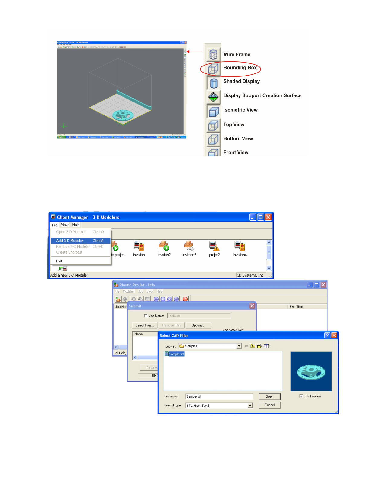
It is not mandatory to switch to Bounding Box Display. However, doing so will allow Print Preview the ability to load more parts into a
single build envelope. The user can also access the Bounding Box Display manually via the "Views" toolbar, by clicking on the "Bounding
Box Display" icon.
Page 29
1.
2.
3.
8.2 Save a Build Job
Prepare and save build job(s) on your PC. Later, submit the job, skipping preparation steps. A saved job is specific to a single PC and can only
be built or deleted from that PC.
Click a modeler's icon in 3-D modelers window to open modeler's Info window.
Select Job name to be saved.
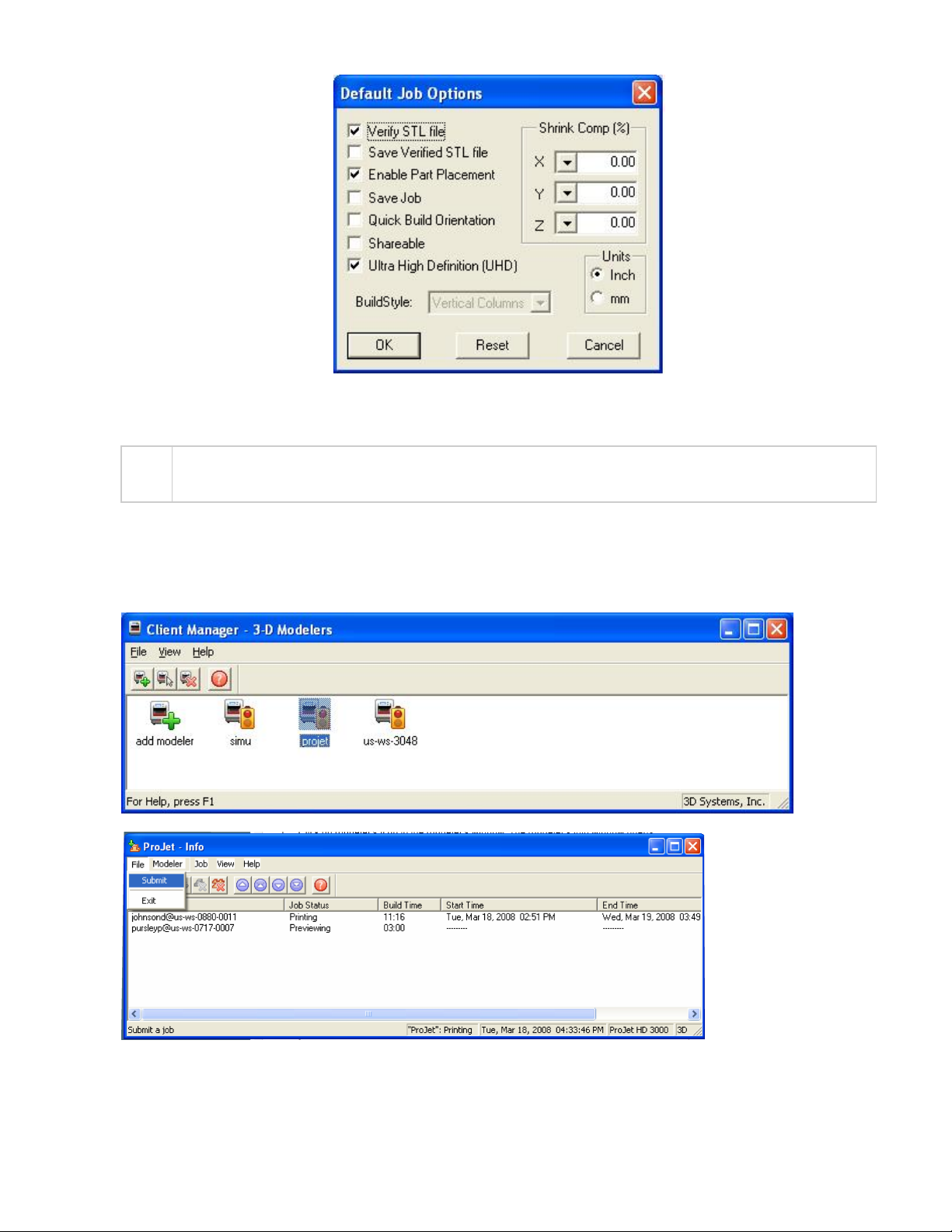
Choose . Job > Default Options
Page 30
3.
4.
1.
2.
3.
In the Default Job Options, select , then click . Save Job OK
NOTE: Jobs to modelers' queue cannot be saved unless Save Job was selected. When a build job with the Save Job option enabled
reaches Pending status, another job (with the suffix "_s") is added to the queue. For more information see , ,Saving Repeat
and Build Jobs in your ProJet Client online Help for more information.Confirming
8.3 Submit a Build Job
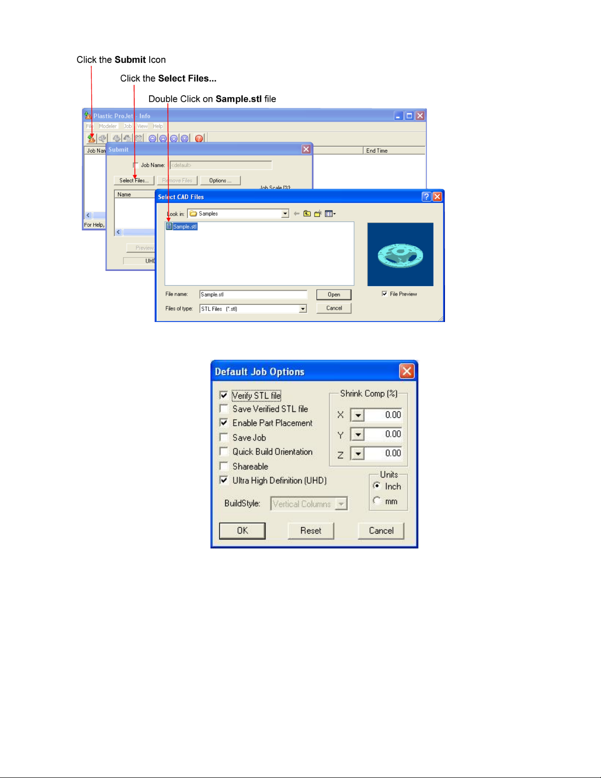
Click on modeler's icon in the modeler's window. The modeler's Info window opens.
In modeler's Info window, click to open Submit dialog box. Submit
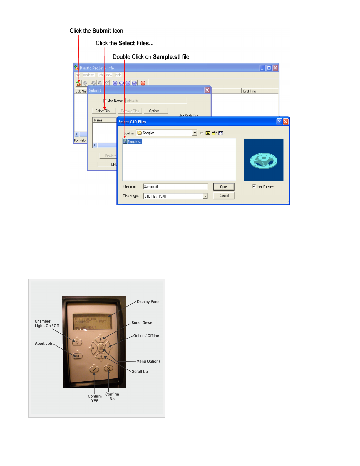
Click on the Submit dialog box to add one or more parts to the build job. Select Files NOTE: More than one STL file can be selected
In Select CAD Files dialog box, hold down the Ctrl key and click on several STL files. Add parts in Preview window. After youat a time.
have added at least one STL file, use Preview window to view build jobs in three dimensions, and to add more STL files if desired.
Page 31
3.
4.
5.
6.
7.
Sample STL files are in the \3-D Modeling Client\Samplesfolder.
Browse files in Select CAD files window. When files are selected, file names appear in build job parts list of Submit dialog box.
Click ...button on Submit dialog box. The Default Job Options dialog box appears. Options
Change or reset values, such as Build Style, Shrink Comp (%), and Units. (See "Default Job Options Dialog Box" in the 3-D Modeling
Client online Help for job options definitions.)
Parts shrink in X and Y. The degree of shrinkage depends on part geometry. To improve part accuracy, apply the X, Y, and Z Shrink
Comp (%) values then measure your parts and refine these values. Refer to .8.10 Shrink Compensation for ProJet VisiJet® Materials
Click on Submit dialog box. If the file you are trying to preview is beyond the threshold of a certain file size, the system willPreview
automatically access the feature. See for details. Bounding Box Display Section 8.1 Preview Build Job
Page 32
8.
9.
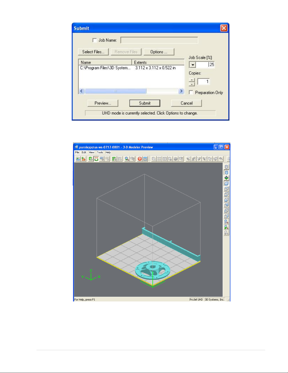
Manipulate parts interactively in the Preview window's virtual modeler 3-D build workspace.
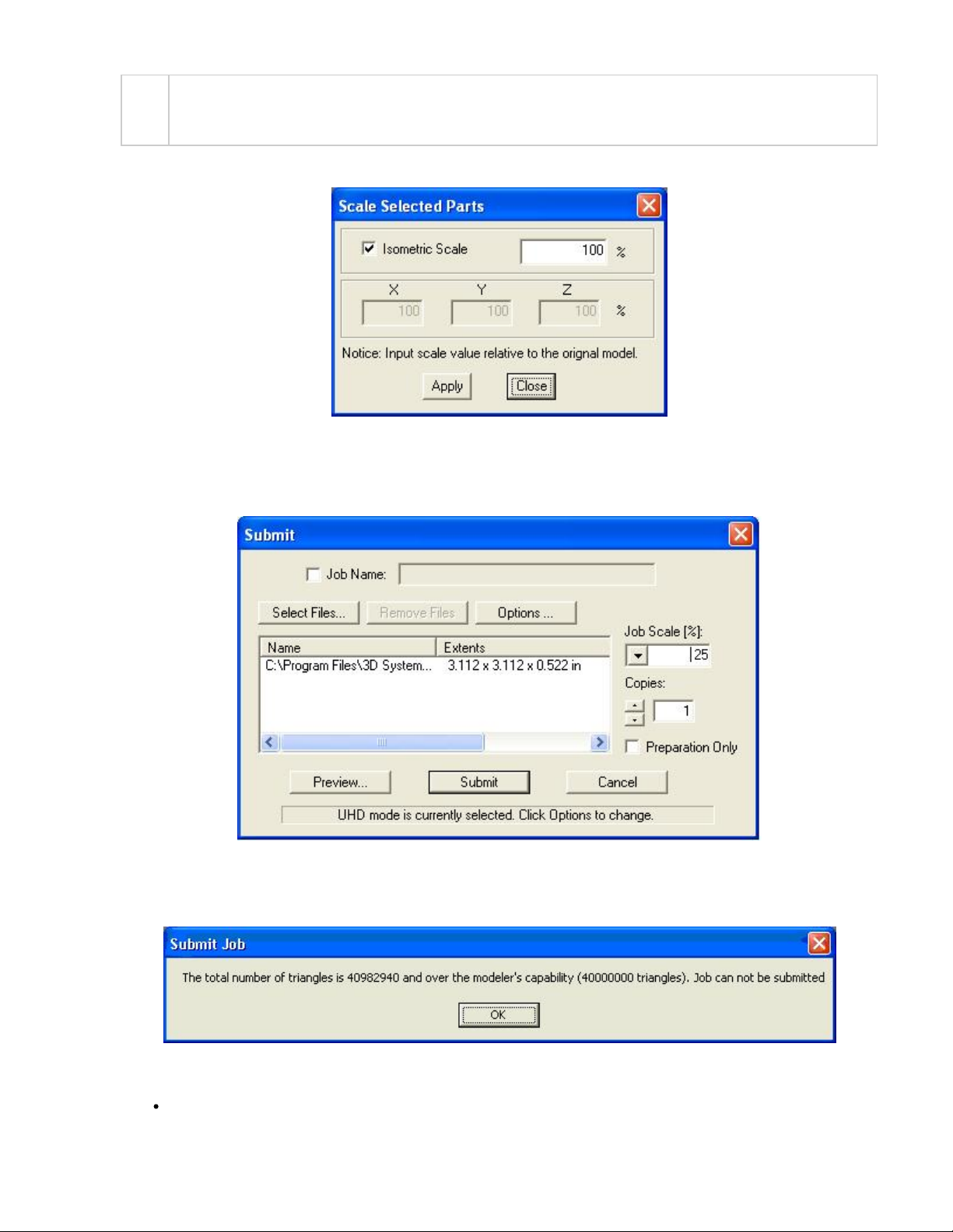
If required, resize all parts in build job by the same scale factor, enter a Job Scale % in the Submit dialog box before clicking t. ToSubmi
resize some of the parts of your job, use in Preview. (See the topic " " in your ProJetEdit > Scale Previewing Print Jobs > Scaling Parts
Client online Help for instructions.)
Page 33
9.
10.
11.
12.
NOTE
Applying Job Scale % (or scale percentage(s) using in Preview)) is different than applying Shrink Comp % valuesEdit > Scale
in the Default Job Options dialog box. Applying scale percentages changes "nominal" part dimensions in the STL file(s).
Applying Shrink Comp percentages does not change nominal part dimensions in the STL file(s). Rather, Shrink Comp adjusts
for expected shrinkage during the build so the actual final part dimensions more closely match the nominal dimensions.
See . Section 8.1 Preview Build Job
Click on Submit dialog box if you did not preview the job, or click toolbar button in the Preview window if you did previewSubmit Submit
the job.
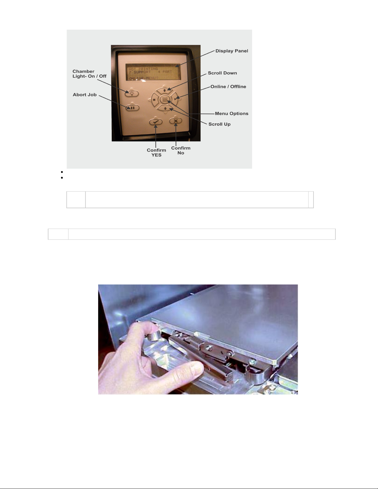
Both the 3-D Modeling Client and Print Preview now check to make sure that the maximum allowable accumulated build file size on the
machine is not exceeded during job submission. The maximum threshold for job submission is roughly two gigabytes or 40,000,000
triangles. If a User attempts to submit a job to the build queue that exceeds this threshold, the following message will be displayed.
The build job submitted will be built when modeler is ready unless:
It is , in which case press the button on the modeler's panel. OFFLINE ONLINE
Page 34
12.
13.
14.
15.
16.
17.
It does not have a clean build platform installed; install clean one and press . ONLINE
The Preparation Only option in the Submit dialog box was checked. This causes the modeler to wait until the build job was
confirmed before building --- enabling you to change the job in the Preview window again before confirming.
NOTE See "Checking modeler Status" and " " in the online Help for more information.Confirming Build Jobs
When the Operator panel LCD shows , verify platform is clean and free of debris. If required, press andPLATFORM EMPTY? Y/N NO
remove build platform from the modeler to replace.
NOTE: Prior to installing a build platform verify both sides of platform and x-carriage mating surface are free and clear of debris.
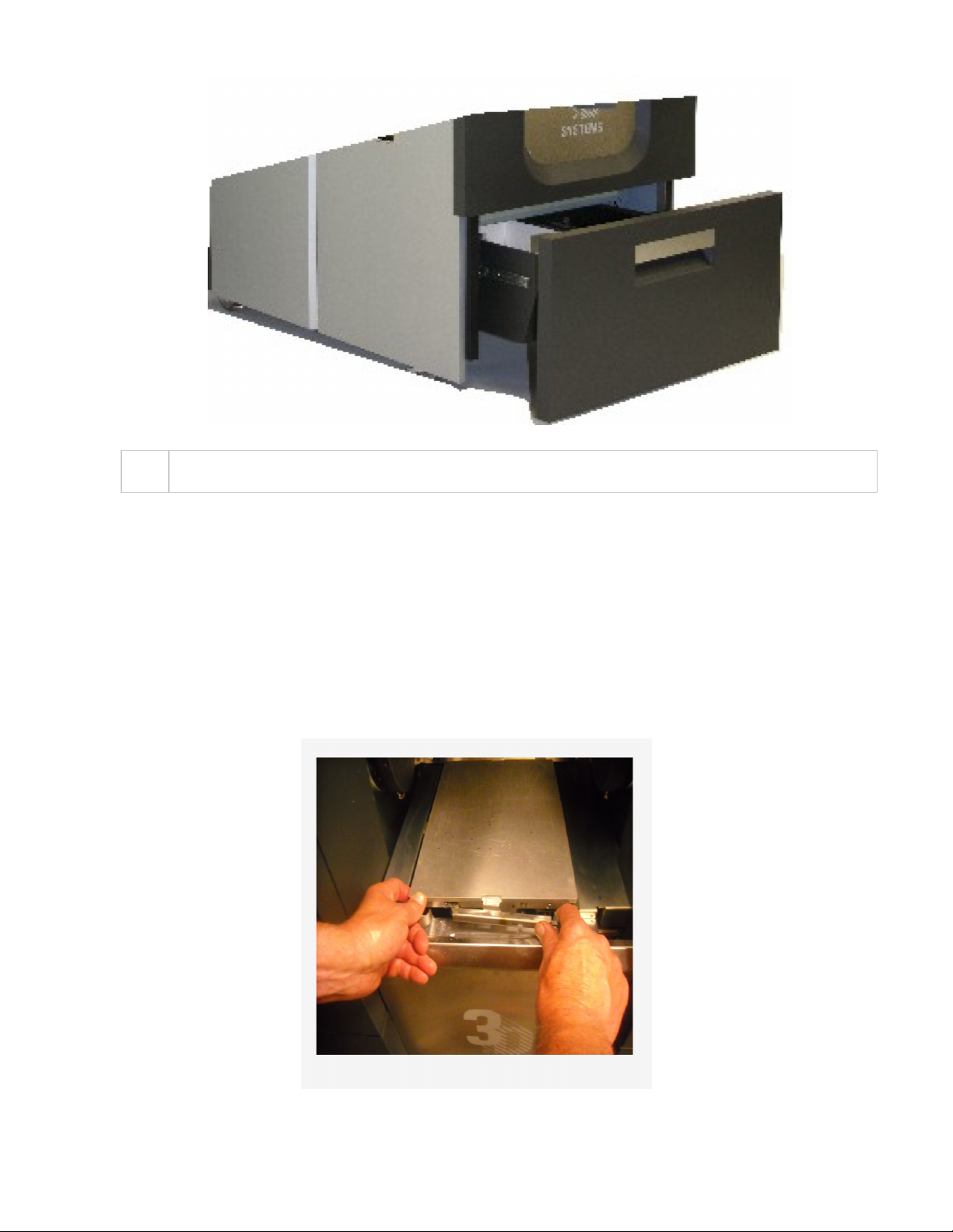
Open chamber door and carefully position rear of clean platform onto X-carriage under tab on back of X-carriage.
\
Lower platform onto X-carriage. While holding onto platform tabs close latch. Ensure latch clicks.
Close chamber door and press . When the Operator panel LCD shows , press . If the displayONLINE PLATFORM EMPTY? Y/N YES
shows please waste or next build will exceed waste capacity, open the waste drawer and dispose of waste material. empty
Close waste drawer. The job starts automatically.
Page 35
17.
18.
1.
2.
3.
NOTE
If the display shows , no jobs are in the modeler's queue. Go back to Step 2 and submit a build job to theWAITING FOR JOB
queue. Once in the queue, the job starts automatically.
Refer to build jobs for additional information. Manage
8.3.1 Remove Build Platform
When operator panel display shows *DONE: <job_name> remove build. Hold X-carriage when removing platform from modeler to prevent damge
of sensors.
Open chamber door.
Open latch securing build platform by pressing inward and releasing.
Lift up build platform and pull out, then a clean platform or close chamber door.install
8.4 Manage Build Jobs
Page 36
1.
2.
3.
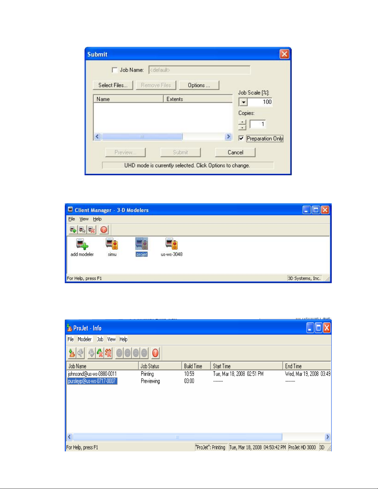
The client software will not send build jobs to the modeler until job confirmed by selecting checkbox on Submit dialog box orPreparation Only
resubmit a saved build job.
Click modeler's icon in client software to open modeler's Info window.
Select build job with of or . Job Status Needs Confirm Saved
Click button or choose located on the tool bar of the modeler window. Confirm Job > Confirm
Page 37
4.
1.
2.
3.
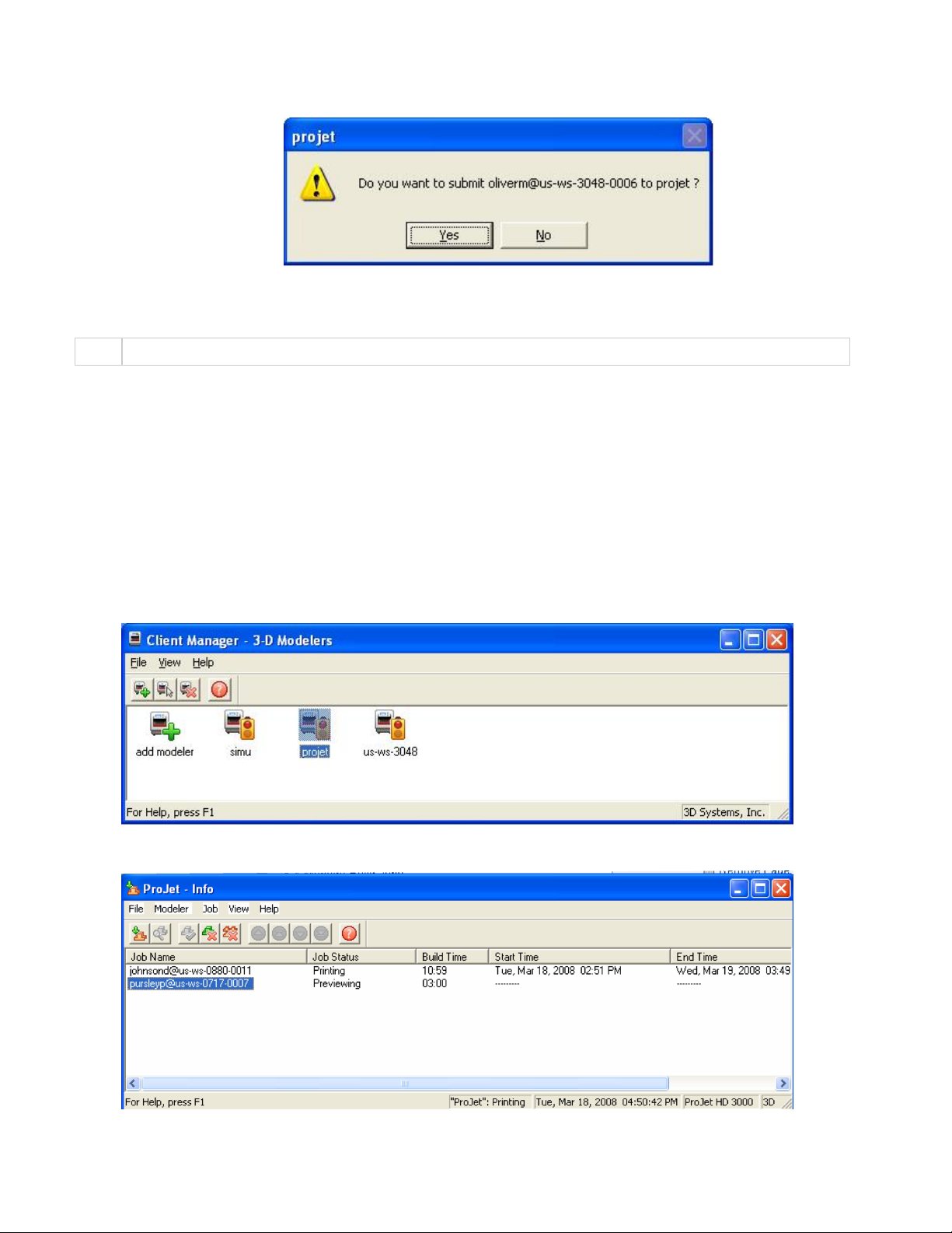
Click Job is sent to modeler as soon as it's available. Yes.
A build job status immediately changes to when confirmed.Needs Confirm Pending
NOTE Confirming saved jobs generates a Pending build job whose name lacks the "_s" suffix. However, saved jobs remain in the queue.
8.4.1 Delete Build Jobs
8.4.2 Pause Build Job
8.4.3 Abort Build Job
8.4.4 Repeat Build Job
8.4.1 Delete Build Jobs
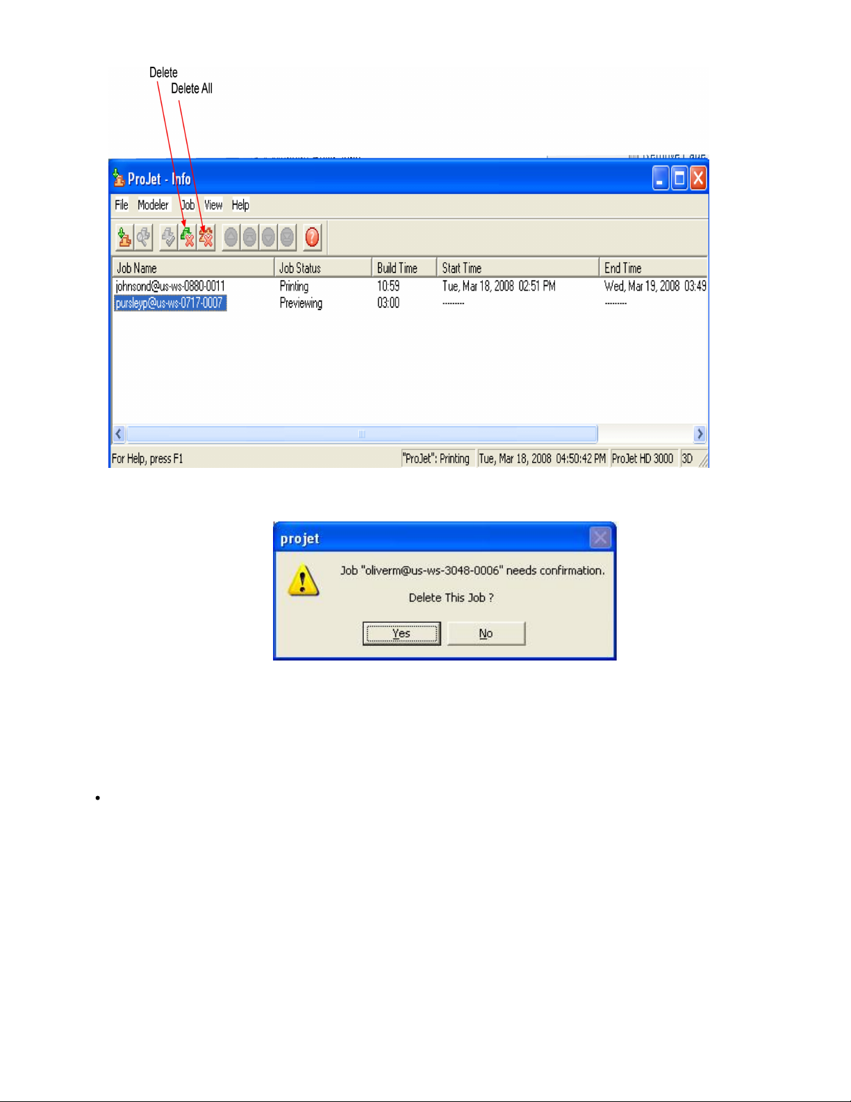
Follow the instructions below to delete one or more jobs from the queue after you submitted.
Click on modeler's icon in modelers window to open Info window.
Select build job(s) to delete. (Ctrl-click to select several jobs.)
Click or button or choose or . Delete Delete All Job > Delete > Delete All
Page 38
3.
4. To delete all jobs, click the button or choose . If you use , and there are saved jobs, the ProJetDelete All Job > Delete All Delete All
Client will ask you if you want to delete saved jobs as well as other ones.
If you delete a job that is currently building; this aborts the operation. However, the job status will continue to show as "Building" at the PC
until deletion is confirmed at the modeler.
8.4.2 Pause Build Job
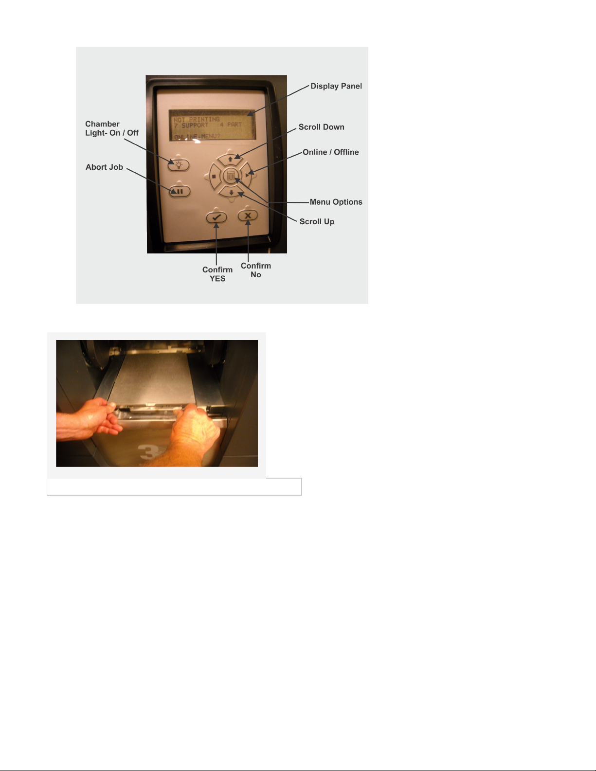
Press . When display shows , press to pause building or to keep building.PAUSE PAUSE jOB? Y/N YES NO
Page 39
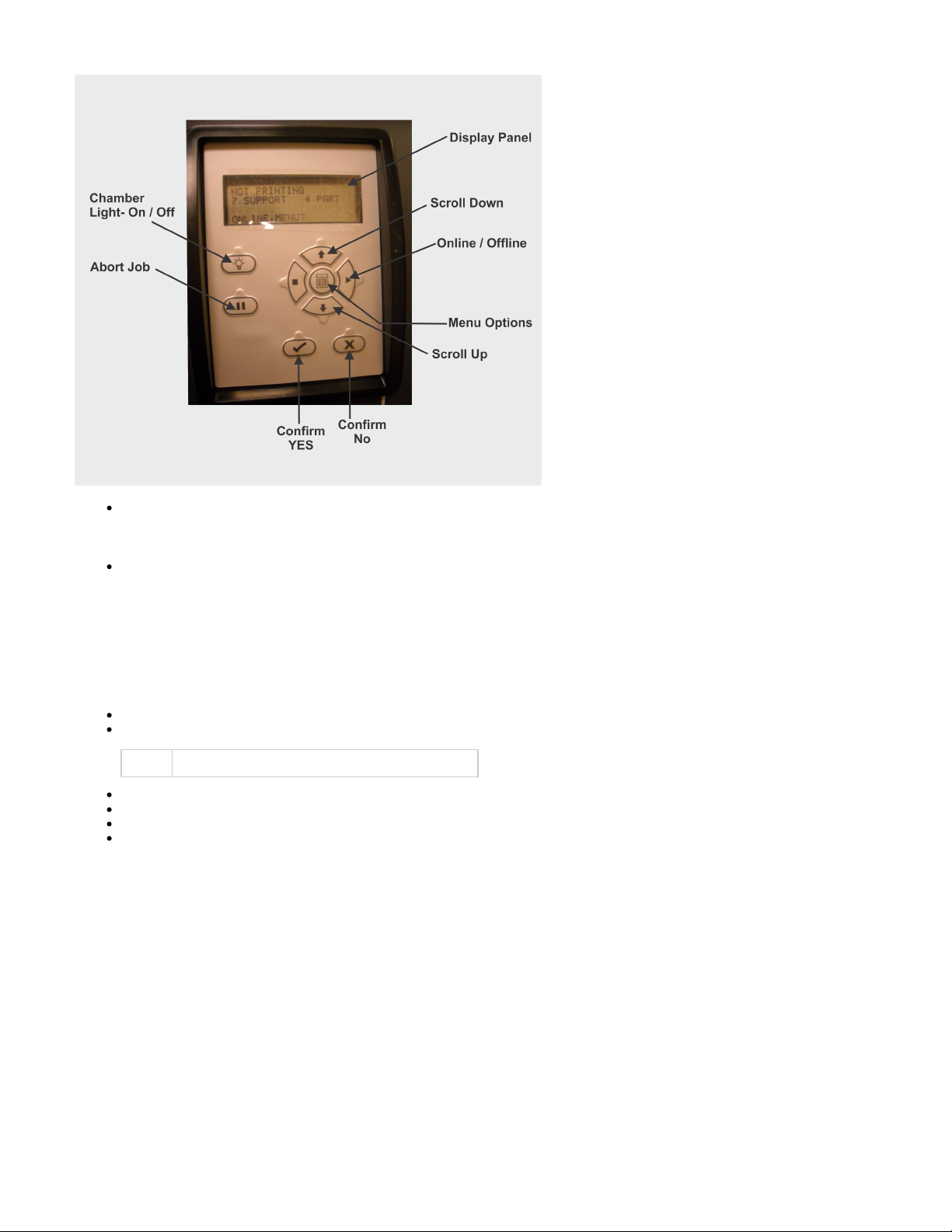
The modeler keeps building after pressing while it displays . If was pressed in response to PAUSE PAUSE jOB? Y/N YES PAUSE JOB?
, the modeler completes current layer or its current task. Then moves the platform forward while chamber door and waste drawerY/N
remain locked. Press again to resume paused job. If you don't press again, the paused job resumes automatically afterPAUSE PAUSE
5 minutes.
If you press in response to , the job does not pause and the confirmation prompt disappears.NO PAUSE JOB? Y/N
8.4.3 Abort Build Job
Press .ABORT
When display shows , press to abort the build job or to continue. The modeler keeps building after you press ABORT JOB? - Y/N YES NO
while it displays If you press in response to , the modeler does the following:ABORT ABORT JOB? - Y/N. YES ABORT JOB? - Y/N
Stops building immediately.
Displays waiting for DSP (Digital Signal Procesor) done.
NOTE: Abort does not finish the current layer or current task.
Displays while it cures any uncured material on the platform.Finishing Build
Displays R as it raises the printhead.aising Printhead
Moves the platform forward and unlocks the chamber door.
Displays:
abort: <job_name>
remove print
Page 40
1.
2.
If you press in response to , the job does not abort and the confirmation prompt disappears.NO ABORT JOB? - Y/N
You can now the platform. remove
8.4.4 Repeat Build Job
NOTE: Do not select Repeat from the Operators Panel after a test print.
Press , scroll to highlight . # Press ; the system displays .MENU REPEAT BUILD YES PLATFORM CLEAR? Y/N
When platform is clear, press . The modeler repeats the previous build job.YES
Page 41
8.5 Modeler Status
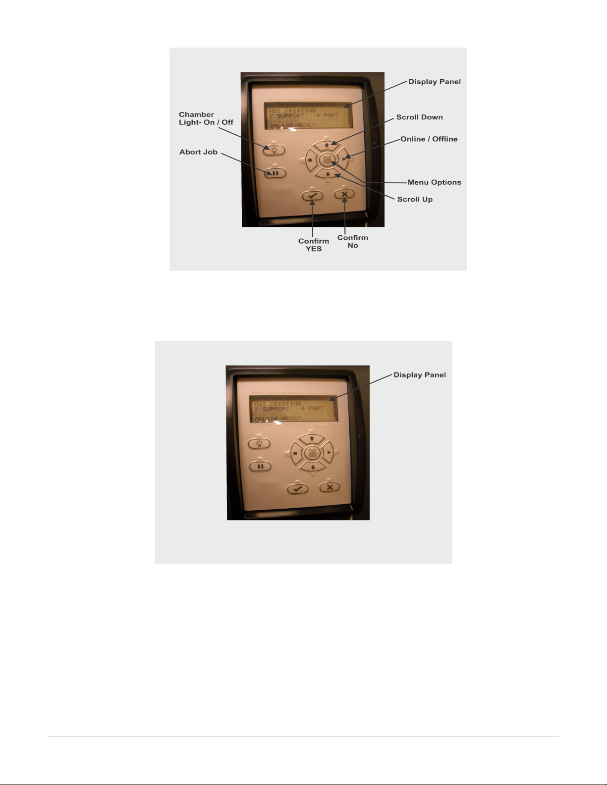
To view the status of the modeler, observe the Liquid Crystal Display (LCD) Panel located on the user interface for elapsed build time, Build time
remaining, material information, job status, name, time remaining on build, error messages, and System Statistics.
8.6 Empty Waste Drawer
Page 42
1.
2.
3.
4.
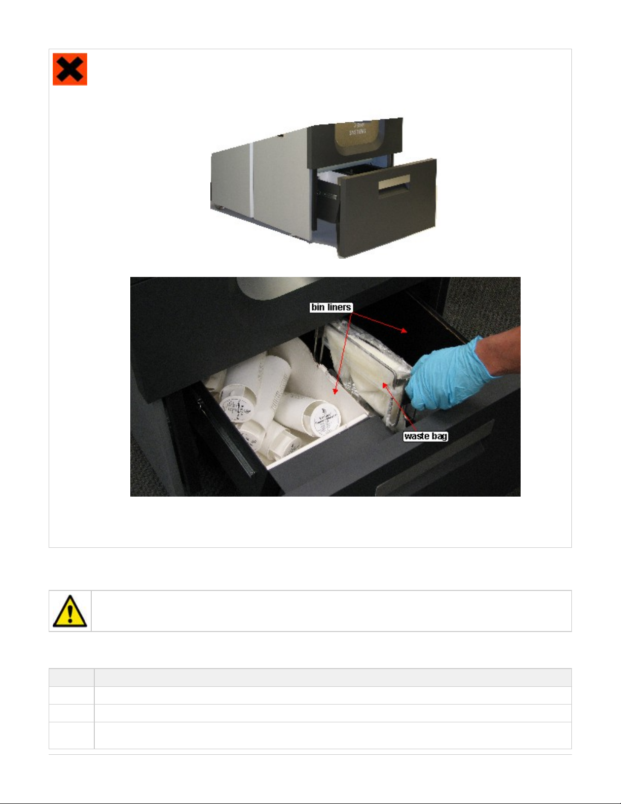
is required before opening waste drawer. Follow all material handling and disposal guidelines. AlwaysPersonal protection equipment
follow MSDS guidelines and local regulations regarding handling and disposal of regulated materials. Keep disposal records if local
law requires.
Open waste drawer.
Remove disposable bin liners with cartridges. Dispose of bin liners and cartridges.
If full, remove, close, and properly dispose of waste bag.
Install new waste bag onto bracket. Tilt bracket with waste bag and install flag into slot in back of waste drawer. Ensure bracket is
properly seated on mouting bracket. Install new bin liners.
Close waste drawer and press to resume.ONLINE
8.7 Shutdown Modeler
WARNING: Switching off or disconnecting the modeler's power without going through a shutdown process can severely
damage the modeler. Always perform shutdown procedures before switching off modeler's power unless power must be
disconnected immediately for safety reasons.
The modeler can take several hours to warm up after being shutdown and switched off. Before shutdown and switching off, verify no need to build
parts again soon.
Mode Clamp Feed
Standby 15 Min.
Conserve 25 Min.
Initial PwrUp90 Min.
Page 43
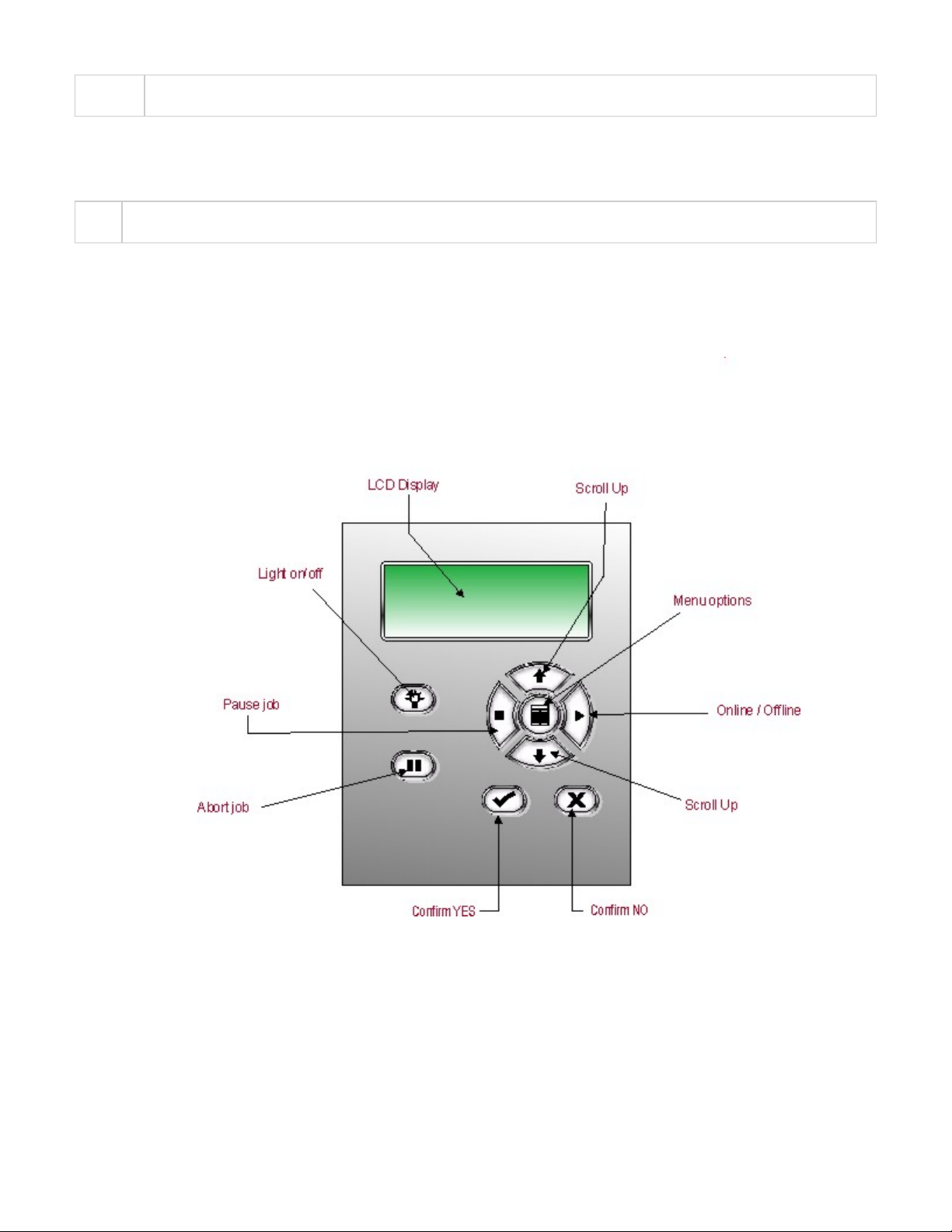
1.
2.
3.
4.
5.
NOTE: It is recommended to leave your modeler in either standby or conserve mode instead of shutting down if the modeler is to be used
within 7 to 10 days of last build.
After modeler is idle 2 hours or 72 hours, it enters Standby or Conserve mode, respectively. In these energy-saving states, the modeler's heaters
are partially cooled and many other components are disabled. The heaters are cooler in Conserve mode more than Standby mode. It takes much
less time for the modeler to warm up from Standby or Conserve mode than it does from full shutdown/power off. Warming up from Conserve
mode takes more time than from Standby.
NOTE To increase or decrease wait time before the modeler enters Standby mode or Conserve mode, contact 3D Systems Technical
.Support
Verify modeler is not building.
Abort current build job.
Press , scroll to highlight . MENU SHUTDOWN
Press twice. YES
When the display shows , press the power switch on the rear panel. OK TO POWER OFF XXX
Page 44
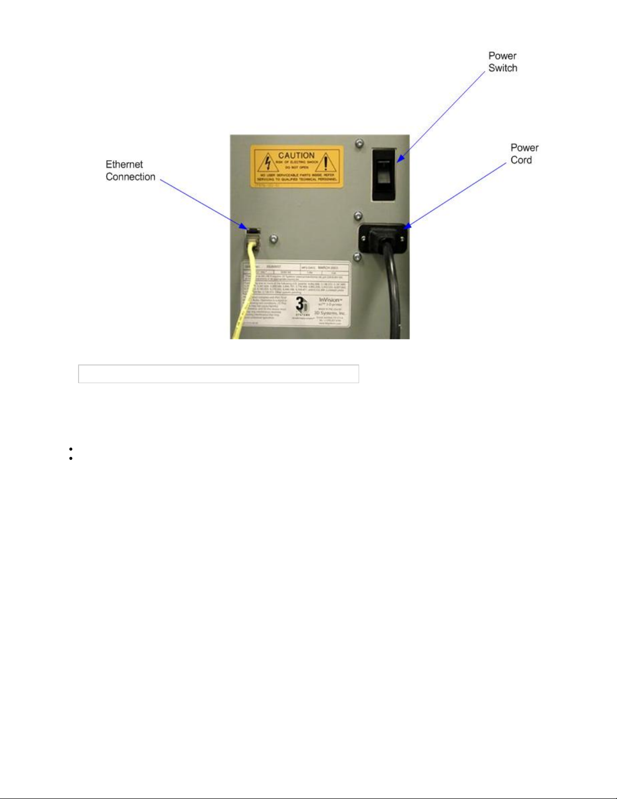
NOTE: To halt shutdown, press before you press the power switch.ONLINE
8.8 Remove Part from Build Platform
Remove build platform from modeler. Refer to .Manage build Jobs
Place warm platform of parts in a freezer for a few minutes. As the parts and platform cool, they contract at different rates and separate.
Alternatively, the parts can be mechanically separated from the build platform by force using a tool such as a thin blade.
8.9 3D Modeling Batch Submission for Production Environment
The Modeler Batch Processor allows users to prepare/send jobs and inquire job status for multiple 3D modelers across networks without using 3D
Modeling Accelerator Client software, which requires human interactions. It is compatible with various 3D Systems' supported 3D Printers,
including ProJet, InVision, and ThermoJet.
The ModelerBatch.exe application reads the job parameters from the given parameter file (.ini file), then prepares, packs and sends the jobs to a
designated printer. The ModelerStatus.exe application allows the user to inquire the job status on a designated printer for both current and
previous jobs including "printing", "pending", "completed", and "aborted".
Modeler Batch Processing
Setting Job Parameters via INI File
Before running the ModelerBatch.exe, a text file must be created that specifies the desired parameters for the pending job. See example below:
Page 45
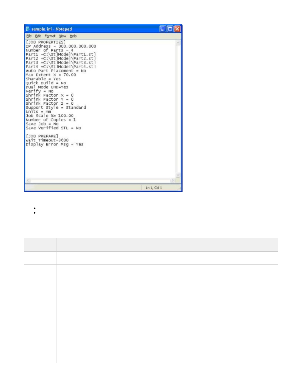
All the job parameters are categorized into two sections:
Job Properties
Job Prepare
The table below provides a description of the ModelerBatch INI parameters.
Parameter
Name
Default
Value
Description Section
Name
IP Address N/A IP address of the designated modeler, e.g., 192.168.0.2 or 192.168.000.002 Job
Properties
Number of
Parts
0 Total number of parts in the job Job
Properties
Part# N/A Full path and name of the STL/CTL file. # must be replaced with numbers which start from 1,
e.g., Part1, Part2, and Part3 ... The total number of parts must be consistent with the total number
of parts.
If a file name is one of:
Modeler_Verification_Strip.STL
Modeler_Verification_Strip_InVision.STL
Modeler_Verification_Strip_ProJet.STL
Modeler_Verification_Strip_ProJetCPX.STL
...then the file is the verficiation strip.
Job
Properties
Auto Part
Placement
No Valid values are "Yes" or "No".
If Yes, the Batch Processor performs auto part placement.
If No, the parts will not be auto placed.
However, the users should ensure the part sizes and positions are appropriate.
Job
Properties
Max Extent X dPlatExtX Max job volume X extent, which is used to position the verification strip for optimal build speed.
The default value is the max platform X extent, which is 6 inches for ProJet 3000 in high resolution
mode.
Job
Properties
Page 46

Sharable No Valid values are "Yes" or "No", which specify if the print job will be shared with other jobs in the
printer.
The print job will not be shared if this field is absent.
Job
Properties
Quick Build No Valid values are "Yes" or "No", which denote whether the parts should be oriented in the printer to
save print time.
Quick build part placement will not be performed if this field is absent.
Job
Properties
Dual Mode
UHD
Yes Valid values are "Yes" or "No", which specify if ultra high resolution (UHD) mode is used to build the
parts.
UHD will be used if this field is absent.
This option is only valid for the modelers with dual-mode capability.
Job
Properties
Verify No Valid values are "Yes" or "No", which specify if verify needs to be performed on the parts.
Verify will not be performed if this field is absent.
Job
Properties
Shrink Factor X
Shrink Factor Y
Shrink Factor Z
0.0 The corresponding shrinkage compensation factors desired in percentage.
These fields will default to 0 if absent, which means no shrinkage compensation is added.
Job
Properties
Supports Style Standard This key defines the type of supports desired.
The Standard supports type will be used if this field is absent.
Valid values are Standard, Vertical Columns, Universal Std, or Universal HiRes.
Job
Properties
Units Inch This key defines the units for the job.
The units will default to Inch if this field is absent.
Valid values are Inch or mm.
Job
Properties
Job Scale % 100.0 The key indicates the scaling desired for the print job.
The scale will default to 100% if this field is absent.
Job
Properties
Number of
Copies
1 This key defines the number of copies of the specified parts in the list.
The default is to created one copy for each part in the job.
Job
Properties
Save Job No The key is used to specify whether the job is to be saved in addition to printing.
The job will not be saved if this field is absent.
Valid values are Yes or No.
Job
Properties
Save Verified
STL
No The key is used to specify whether the verified STL is to be saved in the same folder of the STL file
using the name STLFileName_v.stl.
The verified STL will not be saved if this field is absent. Valid values are Yes or No.
Job
Properties
Wait Timeout 3600 The key denotes the allowed wait time to send jobs from the client to the modeler.
The wait time depends on the client computer and network speeds.
If the wait is more than the allowed wait timeout, the ModelerBatch.exe will be aborted.
The default allowed wait timeout is 3600 seconds (or 60 minutes).
Job
Prepare
Display Error
Message
Yes The key denotes whether to display an error message dialog (i.e. - Pop-up message) if any error
happens.
Job
Prepare
Running the application
The ModelerBatch.exe application can be invoked from command line or program. The command line format is as follows:
RootDir\bin\ModelerBatch.exe IniFile ReportFile
Descriptions:
- the installation folder of the ProJet client, which can be obtained from the registry by using:RootDir
Key = "HKEY_LOCAL_MACHINE\SOFTWARE\3D Systems\3D Modeling Accelerator"
Name= "RootDir"
ReportFile - returns a report to a specified file on the job submission
Note: If a filename is not specified for the report file, the data will be written to a default file named ReportFile.txt. This file will be overwritten every
time the modelerbatch.exe or modelerstatus.exe applications are run without a report file specified
The DOS window show below is an example of running the ModelerBatch.exe via command window.
Page 47
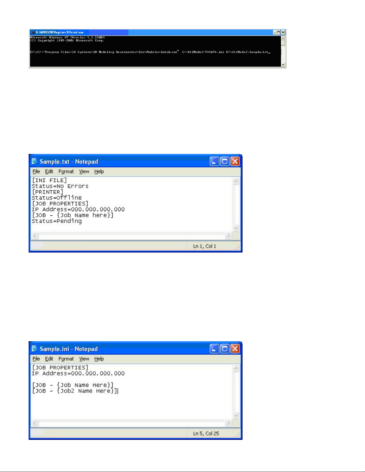
Note: If any of the directories specified in the command script have folders with spaces in the folder name quotes will required around the
directory structure for the script to work. If no spaces are present, the quotes are unnecessary.
Example: "C:\Program Files\3D Modeling Accelerator\Bin\ModelerBatch.exe"
Output Report
After a successful run of the modelerbatch.exe application, the job will be submitted to the designated modeler's build queue and the application
will output a report (ReportFile or IniFile) to the location designated in the command script. The figure below is an example of the report output
after the ModelerBatch.exe completion.
Modeler Status Reporting
Setting up Status INI File
Before running the ModelerStatus.exe, a text file must be created that specifies the desired machine. See example below.
Page 48
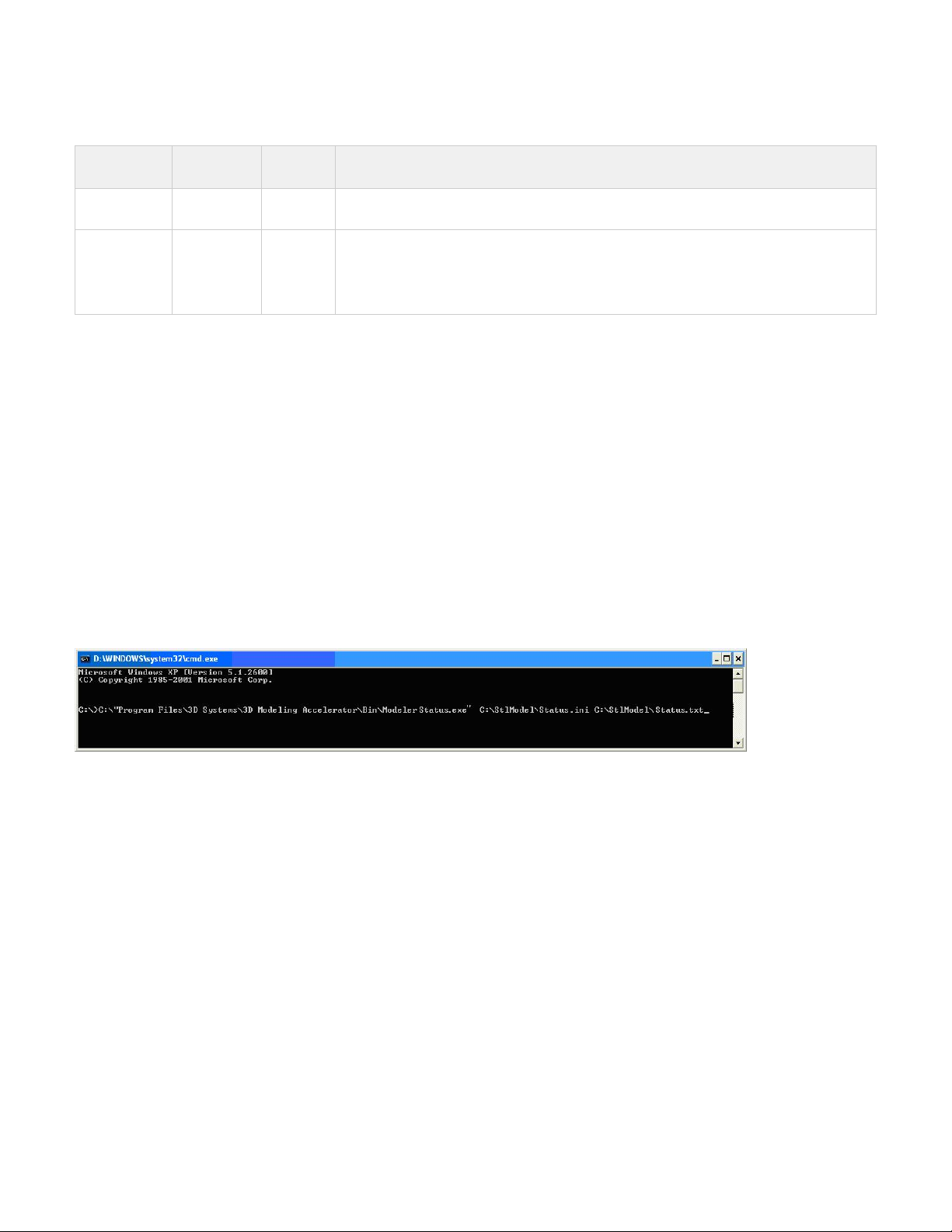
The table below provides a description of the ModelerStatus INI parameters.
Section Name Parameter
Name
Default
Value
Description
JOB
PROPERTIES
IP Address N/A IP address of the designated modeler, e.g., 192.168.0.2 or 192.168.000.002
JOB JobName
N/A N/A The job names are not necessary to request current modeler status.
However, individual job status will only be returned to the output ReportFile if the job names are
specified in the INI file.
The job name is formatted as "JOB - username@ComputerName-####", where ####
represents the 4-digit job number.
Running the application
The ModelerStatus.exe application can be invoked from command line or program. The command line format is as follows:
RootDir\bin\ModelerStatus.exe IniFile ReportFile
Descriptions:
- the installation folder of the ProJet client, which can be obtained from the registry by using:RootDir
Key = "HKEY_LOCAL_MACHINE\SOFTWARE\3D Systems\3D Modeling Accelerator"
Name="RootDir"
ReportFile - returns a report to a specified file on the job submission
Note: If a filename is not specified for the report file, the data will be written to a default file named ReportFile.txt. This file will be overwritten every
time the modelerbatch.exe or modelerstatus.exe applications are run without a report file specified.
The DOS window show below is an example of running the Modelerstatus.exe via command window.
Output Report
After a successful run of the modelerstatus.exe application, the application will output a report (ReportFile or IniFile) to the location designated in
the command script. See example below.
Page 49
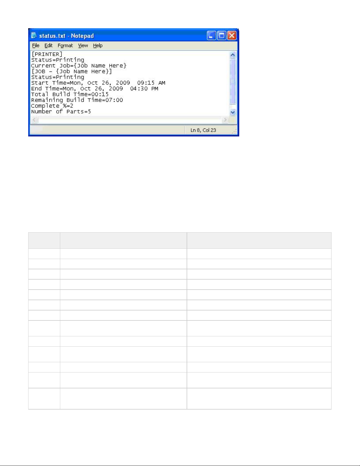
If building in UHD Mode, "Number of Parts" includes the Verification Strip in the part total.
After a machine is put "Online", there is a period of time that a job takes to initialize. During that time, the Status returned will be "Not Printing" and
the End Time, Total Build Time and Remaining Build Time will all report "Not Estimated". Once the state changes to "Printing", these values will
be reported accurately.
Exit Error Codes
The Modeler Batch Processing applications including ModelerBatch.exe and ModelerStatus.exe will return exit error codes if there are any issues
while the application is running. The following table gives a description of each possible error code that may be reported while running either
application.
Exit Error
Code
Error Description Suggested Solution
0 No Error
500 The iniFile is not specified for batch processing Specify the parameter IniFile as the argument
501 The specified iniFile does not exist or cannot be opened Please make sure the IniFile exist
502 IP Address field not present Add the IP address
503 IP address cannot be validated Check the IP address
504 Number of Parts field does not present The number of parts must be specified and larger than 0.
505 STL file for Part# can not be found Missing the STL file. Make sure it exists and accessible.
506 Communication error. Unknown modeler type or
unconnectable modeler.
Please check IP address.
507 Verification Strip file cannot be found. Reinstall the client or restore the verification strip files.
508 Wait timeout. Please verify the network and increase the wait timeout in the
IniFile.
509 Cannot connect to the modeler. Please check IP address.
510 Part outside platform or exceed platform size Check the size and position of all parts to ensure that they will fit
inside the platform
511 Too much part data for Auto Part Placement or Quick
Build Placement
Please not use Auto Part Placement or Quick Build.
For example, use Print Preview and manually position the
gemetries.
Page 50
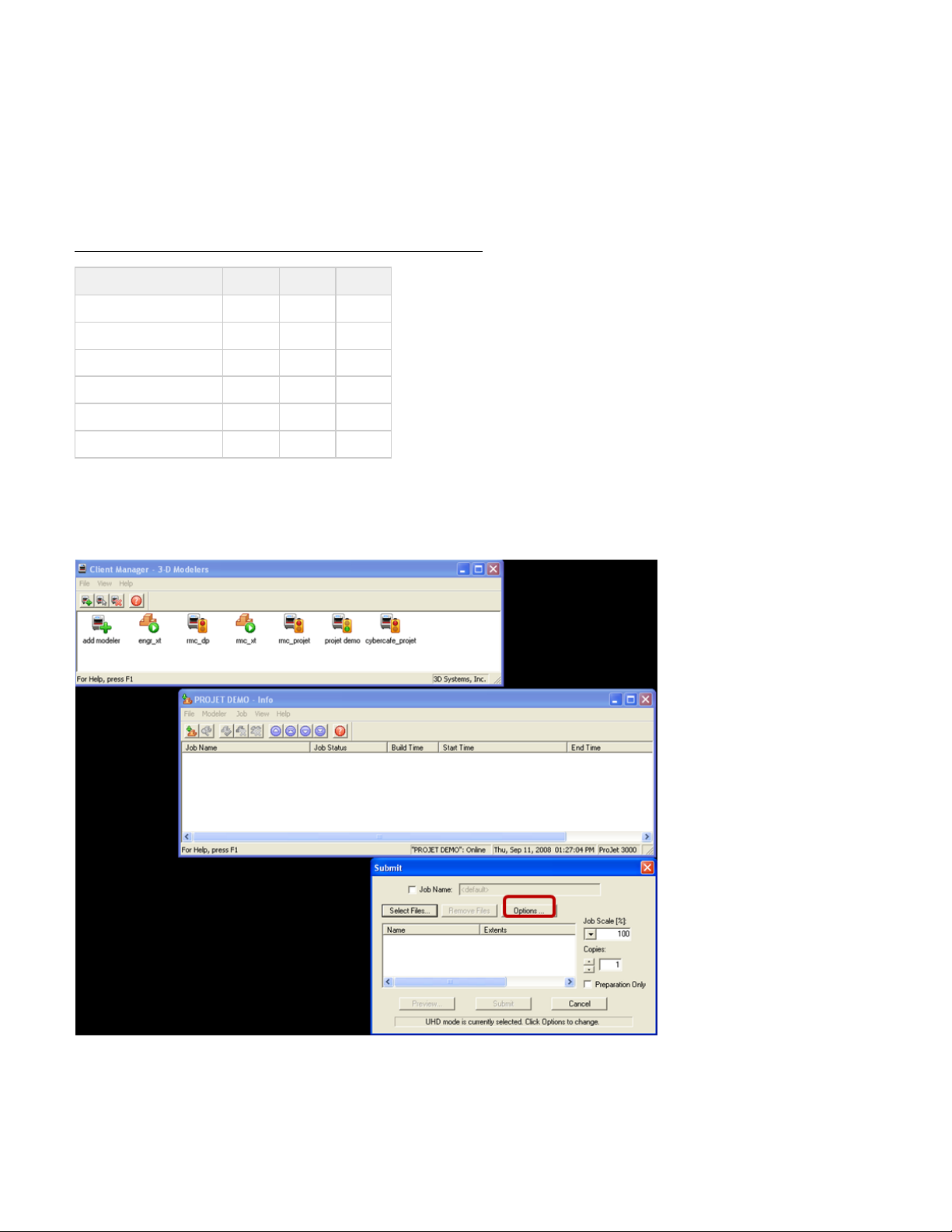
8.10 Shrink Compensation for ProJet VisiJet® Materials
Material shrinkage occurs in thermoplastics as they transition from liquid state to solid state during the curing process.
The ProJet Accelerator Client Software has features that allow the user to compensate for the natural shrinkage of the material in order to fine
tune the accuracy of a part.
These shrink compensation values serve as general guidelines to setting shrink compensation. Part building and cleaning in a controlled process
will best determine the optimal shrink compensation values for a particular geometry.
SHRINK COMPENSATION VALUES FOR VISIJET® PART MATERIALS
Material X value Y value Z value
SR200 (Configuration A) 1.01% 1.01% 0.00%
HR200 (Configuration A 1.01% 1.01% 0.00%
EX200 (Configuration A) 1.01 0.75 0.00
EX200 (Configuration B) 0.50 0.25 0.00
DP200 1.01% 1.01% 0.00%
MP200 1.01 0.75 0.00
1. Enter Standard Shrink Compensation Values for the material.
Open ProJet Accelerator Client software and select the desired modeler. a.
Select the model to build. b.
Select the " " button. c. Options
d. Within the Options panel, enter shrink compensations values for X or Y. Z compensation is rarely necessary (see table above for the values).*
!Shrinkage 3.png|width=300,depth=300|align=right!|
2. Identify the exact X and Y dimensions of the part using a CAD program.
Most CAD programs and simple stl file viewers will provide a way to view a part with its dimensions. a.
Make note of the actual X and Y dimensions as XCAD and YCAD. b.
Page 51
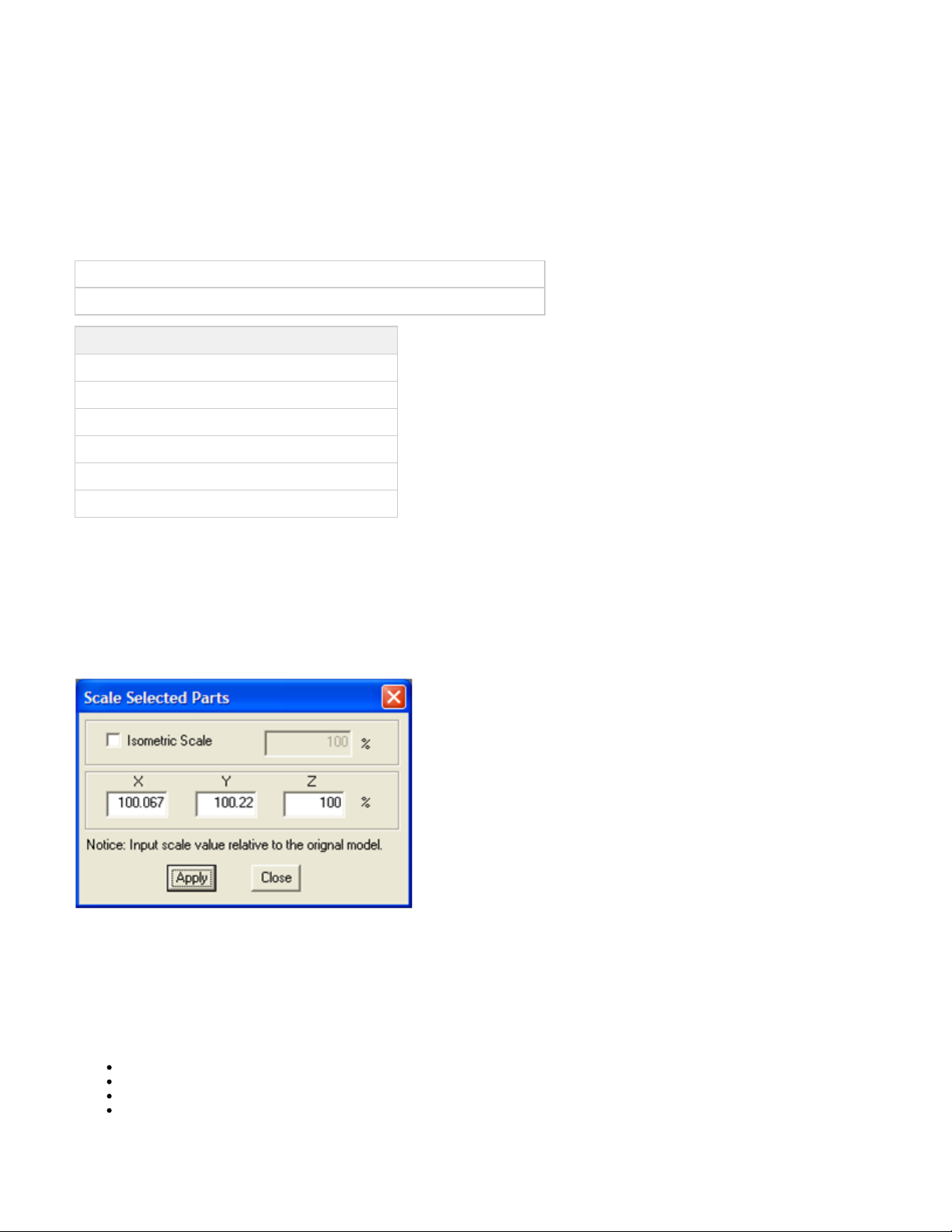
3. Build and clean the part and take measurements of the finished part.
It is recommended to measure along the critical dimensions of the geometry, take measurements in multiple areas and take an average of a.
the values.
Measurements can be made using calipers or more advanced metrology methods. b.
Make note of the X and Y dimensions of the printed part and mark them as XPART and YPART c.
NOTE: If the measurement of the finished part is different from the measurements of the CAD model, fine tune the accuracy using
scaling factors.
4. Determine "Scaling Factor" to use for the next build
Use the following formula calculate the scaling percentage to be used on the "fine tuning" build: a.
X Scaling Factor = (XCAD - XPART)/ XCAD * 100 (answer will be as a percentage)
Y Scaling Factor = (YCAD - YPART)/ YCAD * 100 (answer will be as a percentage)
EXAMPLE:
X measurement of CAD model = 3.000"
Y measurement of CAD model = 5.000"
X measurement of printed part = 2.998"
Y measurement of printed part = 4.989"
X Scaling Factor = (3.000 – 2.998)/3.000 *100 = 0.067%
Y Scaling Factor = (5.000 – 4.989)/5.000 * 100 = 0.22%
5. Enter "Scaling Factor" for adjustment build
Open ProJet Accelerator Client software and select the desired printer. a.
Select the model to print b.
Open Print Preview to view the model. Select the model (color should be yellow) c.
Select the "Scale" Icon and enter the dialog box to enter the above scaling factors. d.
Uncheck the "Isometric Scale" button. This allows user to make individual x and y adjustments. e.
In the example above the x scaling factor should be 100% + 0.067% = 100.067% f.
The y scaling factor should be 100% + 0.22% = 100.22% d.
Enter these two numbers in the corresponding scaling boxes for x and y. e.
6. Build Part with Scaling Factors and measure
Additional iterations of adjusting scaling factors and taking measurements may be necessary with certain geometries. a.
09.0 Maintenance
The following general maintenance procedures provided must be accomplished to help maintain high part yield and low modeler down time.
9.1 Cleaning Surfaces
9.2 Cleaning the Waste Drawer
9.3 Preventive Maintenance
9.4 Return Modeler for Repair
Page 52
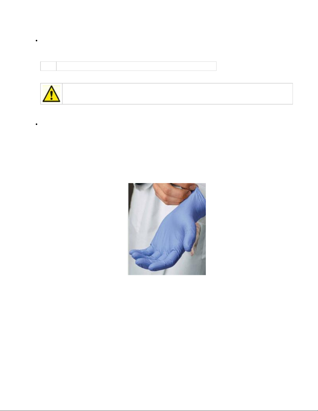
1.
2.
3.
1.
2.
3.
9.1 Cleaning Surfaces
Do not remove any outer panels when cleaning the modeler. Panels must only be removed by qualified 3D Systems Technical Support
Representatives.
Remove dust from outer surfaces of modeler(s) wiping with a clean, dry, lint-free cloth.
NOTE Dust and clean outside surfaces only. Do not dust inside build chamber or feed slots.
Remove dirt and grease from modeler(s) outer surface by spraying all-purpose cleaner on a clean cloth and gently wiping.
Caution: Use only non-abrasive, alcohol-free cleaners to clean surfaces. Do not use all-purpose cleaners
containing petroleum-based polishing agents such as liquid wax. Spray cleaner on cloth, not on surface. Do not
use cleaning solvents on build chamber window do to damage of protective UV coating.
Remove dirt, grease, and build material residue from operator panel buttons, display window, and feed slot door windows using a
ammonia-based glass cleaner on a clean, lint-free cloth gently wiping the buttons and windows.
Remove build platform before cleaning the operator panel buttons. This will prevent the modeler from initiating any actions when buttons
are pressed.
9.2 Cleaning the Waste Drawer
Review VisiJet material handling and disposal safety guidelines in section of this guide before cleaning the waste drawer.Build Material Safety
Clean modeler's waste drawer as follows:
Verify modeler is .OFFLINE
Put on protective gloves. Refer to .Personal Protection Equipment
Open waste drawer. Remove white bin liner, black bin liner, and waste bag.
Page 53
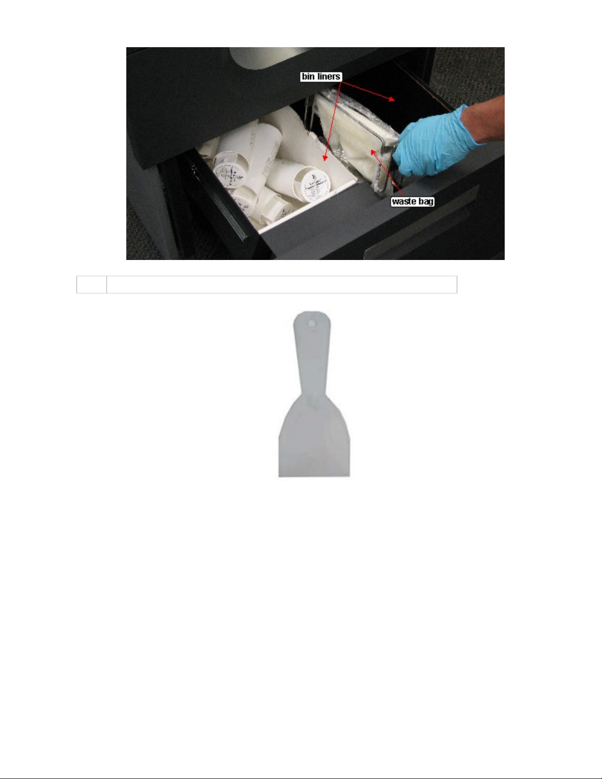
4.
5.
6.
7.
Dispose of bin liners and waste bag if required. Refer to .Disposal
NOTE Insure to reinstall waste bag bracket in correct orientation; with flag in slot at rear of waste drawer.
Gently scrape any material stuck onto interior surface of waste drawer bins. Use a flexible plastic scraper to avoid damaging the paint.
Vacuum inside waste drawer material bins to remove scrapings.
Wipe inside surfaces of waste drawer bins using a clean cloth and all-purpose spray cleaner.
9.3 Preventive Maintenance
Preventive maintenance must be performed by qualified 3D Systems Technical Support Representatives after either one year of total build time,
or consuming 208 lb (94 kg) of build and support materials combined.
The modeler automatically tracks total build time and combined weight of material consumed to date. When either the time or weight limit
mentioned above is reached, its LCD panel will prompt you to contact 3D Systems to schedule a PM visit. When prompted,Technical Support
schedule PM as soon as possible in keeping with the terms of your 3-D modeler warranty.
9.4 Return Modeler for Repair
Guidelines for repacking the modeler
When shipping the modeler for service or repair, use the original shipping carton and packing material. Shipping damage as a result of inadequate
packing is your responsibility. If you have already disposed of the packing material, contact 3D Systems for information onCustomer Support
repacking the modeler.
10.0 Error Messages
Page 54

There are three primary types of error messages which could appear on the operator display panel of your modeler. The primary types of error
messages found will be , , and .Build Material 10.3 Status and Message Lines
10.1 Build Messages
10.2 Material Messages
10.3 Status and Message Lines
10.1 Build Messages
Use these messages to help you manage print jobs before, during, and after printing. The causes of and actions to take in response to various
messages are described in the following table:
MESSAGE CAUSE ACTION
XX:XX......XX:XX 7
SUPPORT....7 PART
PRINTING
The modeler is currently building.
The display shows the elapsed and remaining build time on the top line and the
number of cartridges in the each feed slot on the second line.
NOTE
Add material when the number of cartridges in a slot is 3 or less.
None
NOT BUILDING
The modeler is ready to build.
Press to build or ONLINE
to list menu options.MENU
ProJet™ [X.X] month dd
yyyyTIME XX:XX:XX
When modeler is initially powered-up the latest version of software is briefly
displayed.
NOTE
This is the ProJet modeler's control code version; not the ProJet
Client software version.
None
10.2 Material Messages
Use the following messages to help manage build jobs before, during, and after building. The causes and actions to take to various messages are
described below:
MESSAGE CAUSE ACTION
Page 55
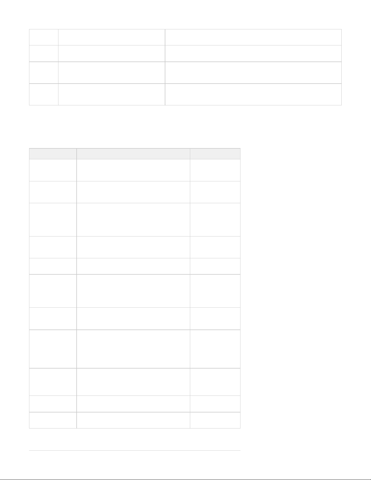
#X PART
The current number of black model ("part")
material cartridges in the right feed slot.
None
#X
SUPPORT
The current number of white support material
cartridges in the left feed slot.
None
ADD
PART
The maximum number of model material
cartridges in the right feed slot is 9.
Add model material cartridges.
The feed slot is full when five cartridges are visible in the window (maximum
number of cartridges per slot is 9). as requried.Add cartridges
ADD
SUPPORT
The maximum number of support material
cartridges in the left feed slot is 9.
Add support material cartridges.
The feed slot is full when five cartridges are visible in the window. Add
as required.cartridges
10.3 Status and Message Lines
Messages appear either on the Status line or the Message line. Read both lines together to determine the exact state of the modeler. The Status
line generally indicates current state of the modeler. The Message line shows the action to take to complete a function and move to the next step.
MESSAGE CAUSE ACTION
ABORT button pressed. Refer to .ABORT abort build job Press to abortYES
or to cancel theNO
command.
ABORT
ACKNOWLEDGED
You confirmed an abort command. The modeler is
aborting the current job.
None.
Refer to abort build
.job
BUILD PAUSED button pressed during the build. The buildPAUSE
platform moves forward and the chamber door
and waste drawer remain locked. When you press
the button during a build, the modelerPAUSE
completes its current task before stopping.
Press toPAUSE
continue. Refer to
build job.pause
CLEANING
PRINTHEAD
The modeler is cleaning the build jets. None. (This occurs
automatically before
every build.)
CLOSE DOORS
The chamber door is open. Close the chamber
door.
CONFIRM
PLATFORM
CLEAR OR
CANCEL
The modeler is prompting you to verify the
platform is clean and clear of obstructions. Refer
to of build platform.installation
Verify the platform is
clean and clear, then
press toYES
continue or press
to cancel.ABORT
PRESS PAUSE
TO CONTINUE
The modeler is paused.
Press toPAUSE
continue or ABORT
to cancel.
CYCLE POWER
TO CONTINUE
A severe error occurred. The modeler cannot
recover from it and must be switched off.
Cycle power to the
modeler. If the error
message occurs
again, contact your
Technical Support
Hotline.
DONE REMOVE
BUILD
The modeler completed building the current job. Remove the
platform. Refer to
of buildremoval
platform.
HOMING
PRINTHEAD
The modeler is initializing the Z-axis prior to
building.
None.
HOMING X - Y
The modeler is initializing the X-axis and Y-axis
prior to building.
None.
Page 56
INSTALL
PLATFORM
The modeler cannot detect a platform. Install a clean
platform. Refer to
of buildinstallation
platform.
NOT BUILDING
The modeler is ready to build.
Press toONLINE
build or to listMENU
menu options.
OK TO POWER
OFF
The modeler completed its internal shutdown
procedure and is ready to be shutdown.
Refer to modeler .shutdown
Toggle power switch
on modeler rear
panel to the OFF
position.
NOTE Before you switch power off, verify
you will not need to build parts
again soon. It can take several
hours for the modeler to warm up
after you switch power back on.
ONLINE/MENU?
The modeler is ready to build.
Press toONLINE
build, to listMENU
menu selections.
PAUSE
ACKNOWLEDGE
The button was pressed. The modeler isPAUSE
acknowledging and complying with the command.
None. NOTE
If you press during a printPAUSE
job, the current layer or process is
completed before the pause takes
effect.
PLEASE WAIT
The modeler is cooling to shutdown temperature. Wait for the modeler
to complete its
shutdown
procedures. Refer to
modeler .shutdown
PRE-JOB
CHECKS
Briefly displayed during modeler build preparation. None.
BUILDING
The modeler is currently building. Allow the build job to
continue or press
or PAUSE ABORT
to stop building.
RAISING
PRINTHEAD
The modeler is raising the printhead so you can
remove the platform.
None.
REMOVE BUILD
The modeler completed a build job and unlocked
the chamber door so you can remove the platform.
Remove the platform
and replace it with a
clean platform.
Refer to ofremoval
build platform.
SHUTDOWN IN
PROGRESS
You selected the menu option, thenSHUTDOWN
pressed twice. The modeler is cooling downYES
so power can be switched off. Refer to modeler
.shutdown
None. DO NOT
switch off the
modeler while
shutdown is in
progress.
SHUTDOWN
COMPLETE
Modeler cooldown is complete; modeler is ready
for power off.
Wait for OK TO
POWER OFF
message, then
switch power off at
the modeler's rear
panel.
NOTE: icon=false}Before you switch power
off, verify you will not need to build
parts again soon. It can take
several hours for the modeler to
warm up after you switch power
back on. Refer to modeler
.shutdown
STANDBY
The modeler is in energy-saver mode. All internal
subsystems are partially cooled and the modeler
is inactive.
None.
The modeler will
warm to operating
temperature when
you press any button
or submit a build job.
Page 57
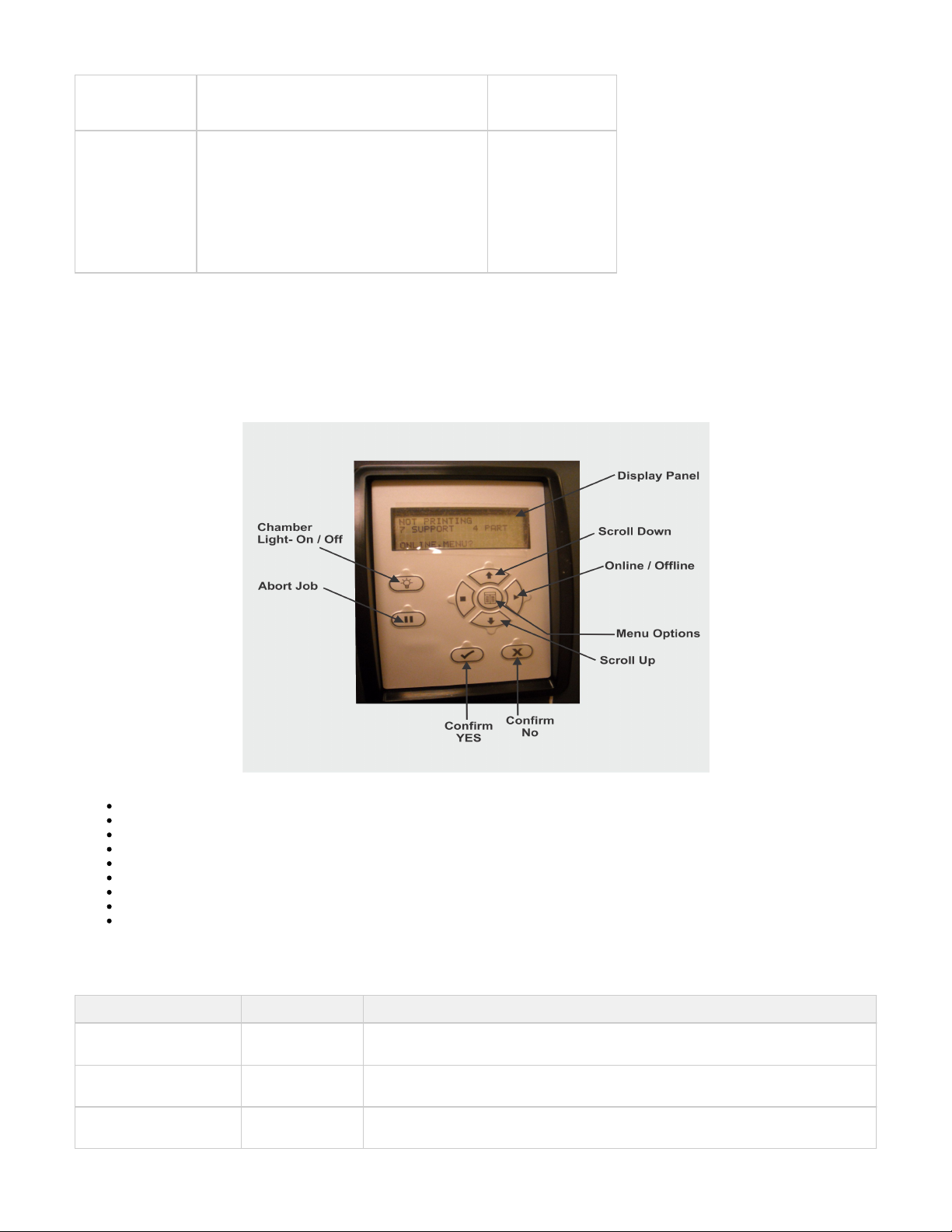
WAITING FOR
JOB
The modeler is online, but there is no build job in
it's queue. The modeler is ready to build as soon
as it receives a job.
Submit a build job to
the modeler. Refer
to a build job.submit
WARMING STAGE
[4,3,2,1]
The material heaters and printhead jet heaters
gradually warm up to either standby or build
temperature.
None.
The numbers on the
LCD panel count
down as the modeler
warms up.
At Warming Stage 1
, all heaters and
material are at build
temperature.
11.0 Troubleshooting
If problems occur with the modeler, error messages appear on the LCD of the Operator's panel. Refer to appropriate troubleshooting table for
assistance. There may be times when an unrecoverable error message will appear and will require a call to Hotline. Prior toTechnical Support
contacting Technical Support Hotline ensure you have serial number of the modeler, a brief description of the problem including exact error
message displayed on the LCD panel, and when the problem occurred (while submitting a job, during the beginning or end of the build, after
power off recovery, etc.).
11.1 Communication Errors
11.2 Head Maintenance Station Errors
11.3 Material Feed and Waste System Errors
11.4 Material Quality Guarantee Errors
11.5 Material Waste Errors
11.6 Motion System Errors
11.7 UV Subsystem Errors
11.8 Vacuum Regulator Errors
11.9 Power Outage
11.1 Communication Errors
MESSAGE CAUSE ACTION
RT_ERROR: No machine
Identification (ID)
No network
connection.
Ensure you have a valid network connection. Cycle power to the modeler. If error
message occurs again, contact your Hotline.Technical Support
evm6x_hpi_open()
A communication
error occurred.
Cycle power to the modeler. If this does not restore communication, contact your
Hotline.Technical Support
evm6x_init_emif()
A communication
error occurred.
Cycle power to the modeler. If this does not restore communication, contact your
HotlineTechnical Support
Page 58
11.2 Head Maintenance Station Errors
MESSAGE CAUSE ACTION
HMS ERROR
Recovery
An error occurred during printhead maintenance (cleaning
the printhead before beginning a build).
Cycle power to the modeler. If error message occurs again,
contact your Hotline.Technical Support
11.3 Material Feed and Waste System Errors
A just loaded cartridge did not engage correctly during the material feed cycle or the printhead sensors did not detect the required material level.
MESSAGE CAUSE ACTION
RT_ERROR: AirPurge 1
(or 2) Not Responding
Fault detected in control circuitry. Cycle power to the modeler. If error message
occurs again, contact your Techncial Support
Hotline.
RT_ERROR: AirPurge 1
(or 2) Position Error
Fault detected in control circuitry. Cycle power to the modeler. If error message
occurs again, contact your Techncial Support
Hotline.
RT_ERROR: AirPurge 1
(or 2) Position Error
Fault detected in control circuitry. Cycle power to the modeler. If error message
occurs again, contact your Techncial Support
Hotline.
Material 1 (or 2) Index
Dump Error
Feedback did not indicate whether the indexer reached the
specified position.
Contact your Hotline.Technical Support
Material 1 (or 2) Index
Load Error
Feedback did not indicate whether the indexer reached the
specified position.
Contact your Hotline.Technical Support
Material 1 (or 2) Index
feed Error
Feedback did not indicate whether the indexer reached the
specified position.
Contact your Hotline.Technical Support
Material 1 (or 2) Index
Timeout Error
Communication failed to report the indexing operation was
completed
Contact your Hotline.Technical Support
RT_ERROR: Index
Drum 1 (or 2) Temp Out
of Range
Possible faulty heaters. Cycle power to the modeler.
If error message occurs again, contact your
Hotline.Technical Support
RT_ERROR: material
feed 1 (or 2) can't fill
head
A just loaded cartridge did not engage correctly during the material
feed cycle or the printhead sensors did not detect the required
material level.
Cycle power to the modeler.
If error message occurs again, contact your
Hotline.Technical Support
Material 1 (or 2) Pump
Retract Error
The retracting plunger was not detected. Contact your Hotline.Technical Support
Material 1 (or 2) Pump
Engage Error
A new cartridge has been indexed but did not satisfy the sensors. Contact your Hotline.Technical Support
11.4 Material Quality Guarantee Errors
MESSAGE CAUSE ACTION
Support (or build)
material cartridge
not detected
Modeler is out of material cartridges, a cartridge
misfed, or the material identification system is faulty.
The build will abort if it needs to use the questionable cartridge
to finish the build.
Add the specified material cartridge, l a cleaninstal
build platform and the build job.repeat
If error message occurs again, contact your Technical
Hotline.Support
Page 59
Support (or build)
material cartridge
not melted
A cold cartridge was added to the material feed slot
and it did not have enough time to melt before the
modeler requested material.
The build will abort if it needs to use the questionable cartridge
to finish the build.
Install a clean build platform and the build jobrepeat
after the modeler has reached build temperature.
If error message occurs again, contact your Technical
Hotline.Support
Support (or build)
material cartridge
expired
The material identification system detected expired
material.
Follow the discard instructions posted to the LCD panel.
Support (or build)
material cartridge
incorrect type
A material cartridge was inserted into the wrong feed
slot.
The build will abort if it needs to use the questionable cartridge
to finish the build.
Follow the discard instructions posted to the LCD
panel.
If error message occurs again and you have inserted
the correct material cartridge into the correct feed slot,
contact your Hotline.Technical Support
11.5 Material Waste Errors
MESSAGE CAUSE ACTION
RT_ERROR: draintank not
responding
Fault detected in control
circuitry.
Cycle power to the modeler. If error message occurs again, contact your
Hotline.Technical Support
RT_ERROR: Draintank
Position error
Fault detected in control
circuitry.
Cycle power to the modeler. If error message occurs again, contact your
Hotline.Techncial Support
RT_ERROR: Draintank
timeout error
Fault detected in control
circuitry.
Cycle power to the modeler. If error message occurs again, contact your
Hotline.Techncial Support
RT_ERROR: can't empty
draintank
Sensor or valve
malfunctioned.
Cycle power to the modeler. If error message occurs again, contact your
Hotline.Techncial Support
11.6 Motion System Errors
MESSAGE CAUSE ACTION
X-Following
ERROR
An attempt to open the build chamber door
was made, or position sensor errors occurred.
Ensure the build chamber door is secured, then cycle power to the modeler. If
error message occurs again, contact your Hotline.Techncial Support
Negative
Firing
Delay
Variations in scanning axis velocity. Cycle power to the modeler. If error message occurs again, contact your
Hotline.Technical Support
Pause
Timeout
ERROR
Position sensor contamination. Cycle power to the modeler. If error message occurs again, contact your
Hotline.Technical Support
11.7 UV Subsystem Errors
MESSAGE CAUSE ACTION
Page 60
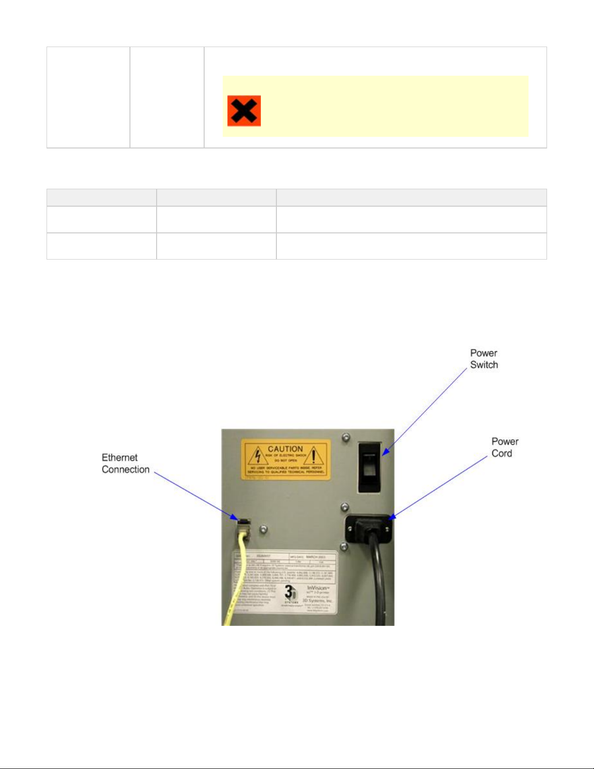
1.
2.
RT_ERROR: UV
Lamp Power Too
Low
UV sensor
detected a
possible fault.
Cycle power to the modeler. If error message occurs again, contact your Techncial Support
Hotline.
CAUTION
To prevent skin exposure to uncured model material, do not handle parts in
a build without wearing gloves if a UV lamp problem occurred during the
build.
11.8 Vacuum Regulator Errors
MESSAGE CAUSE ACTION
RT_ERROR: Printhead
Vacuum Low
Indicates a fault within the
vacuum system.
Cycle power to the modeler. If error message occurs again, contact your
Hotline.Techncial Support
RT_ERROR: Printhead
Vacuum High
Indicates a fault within the
vacuum system.
Cycle power to the modeler. If error message occurs again, contact your
Hotline.Techncial Support
11.9 Power Outage
If you are present during a power outage, or discover the main power OFF, complete the following steps:
Switch power OFF on modeler's rear panel so it does not automatically start when power is restored. This prevents modeler damage due
to power flickers and surges.
When power is restored and stable, switch modeler power ON on the rear panel.
If power outage occurs and is restored before anyone can take action, the modeler will recover as follows:
The modeler advances through warming stages until reaching the required build temperatures. If modeler was not building when power outage
occurred, the top line on the LCD panel will display " " and bottom line will display " ?". The modeler is ready toNot Building Online/Menu
accept a build job.
Page 61
If modeler was building when the power outage occurred, the LCD panel will display " " after power is restored and modelerPower Off Recovery
has reached build temperature. This safety feature prevents accessing incomplete build until all build conditions are satisfied. Once occurred, the
job will end, the LCD panel will display and the build platform will move forward, and can be and build job"Done Remove Build" removed repeat
if desired.
NOTE If the modeler is in Power Off Recovery, the build chamber will not be able to open until modeler completes recovery.
12.0 Finishing
When the build is complete, refer to the for information on how to detach parts from buildVisiJet® Material Handling and Post-Processing Guide
platform, remove support material from parts, and clean parts to a smooth finish.
Basic part coating and equipment maintenance recommendations are also included.
13.0 Projet™ Spare Parts List
13.1 Consumables and Replacement Modules
13.1 Consumables and Replacement Modules
To view the parts and modules that are available, click on the Projet™ Spare Parts Locator.
14.0 Other Documents
14.1 Parts Finisher User Guide
14.2 Material Safety Data Sheets (MSDS)
14.3 Projet™ Quick Reference Guide
14.4 Facility Requirements Guide
14.5 VisiJet® Material Handling and Post-Processing Guide
14.1 Parts Finisher User Guide
When the build is complete, refer to the Parts Finisher Guide for information to detach parts from build platform, remove support material from
parts, and clean parts to a smooth finish.
Basic part coating and equipment maintenance recommendations are also included.
14.2 Material Safety Data Sheets (MSDS)
To obtain a copy of the Material Safety Data Sheet (MSDS) or a Safety Data Sheet (SDS), go to 3D Systems website. . . 3D Systems MSDS
14.3 Projet™ Quick Reference Guide
PROJET 3-D Modelers Quick_Reference Guide.pdf
14.4 Facility Requirements Guide
Projet™ 3-D Modelers Facility Requirements Guide
Page 62
14.5 VisiJet® Material Handling and Post-Processing Guide
VisiJet® Material Handling and Post-Processing Guide
15.0 Service and Support
15.1 Contacts
15.2 How to Order Parts
15.1 Contacts
For information, questions, or comments about ProJet™ 3-D modeler system(s), VisiJet® materials, or request service, please contact a
3D Systems Customer Service or Sales Representative nearest you.
3D Systems
333 Three D Systems Circle
Rock Hill, SC 29730 USA
: 803.326.4080tel
: 803.324.8810fax
: 800.889.2964toll free
: [email protected]email
www.3dsystems.com
Nasdaq: TDSC
Customer Support Hotline
U.S.A. 800.889.2964
Asia-Pacific (+852) 29 23 50 77
Europe (+49) 6151 357-0
Sales and Service
FRANCE tel (+33) 1 69 35 17 17 ITALY tel (+39) 039 68904 00
GERMANY tel (+49) 6151 357-0 JAPAN tel (+81) 3 5451-1690
HONG KONG tel (+852) 29 23 50 77 UK tel (+44) 1442 282 600
SWITZERLAND tel (+41) 26 439 95 90
15.2 How to Order Parts
New and refurbished parts made by 3D System's manufacturer are used when performing warranty repairs and in building replacement parts and
systems. Refurbished parts and systems, are parts or systems that have been returned to 3D Systems, some of which were never used by a
customer. All parts and systems are inspected and tested for quality. Replacement parts and systems are covered for the remaining period of the
limited warranty for the product you bought. 3D Systems owns all parts removed from repaired products.
To order replacement parts, contact or contact your local reseller.3D Systems Customer Service Support
When contacting 3D Systems Customer Service Support, have your modeler serial number available to give to customer support.
16.0 Online Help
• Find Help topics on the Content Pages of each section.
16.1 Frequently Asked Questions (FAQ)
16.2 Getting Help
16.3 Build Material
16.4 Modeler Hardware and Installation
16.5 Facility Requirements
Page 63

16.1 Frequently Asked Questions (FAQ)
General
What is rapid prototyping?
Rapid prototyping(RP)is the process of building a part from a 3D Cad drawing and converting the drawing format into an .STL file. When the
modeling event takes place in the modeler, it is constructed layer by layer using Accura VisiJet® materials.
What is 3D Modeling?
A type of rapid prototyping, typically defined by faster, more affordable, and easier-to-use technologies.
How does 3D Modeling fit into the design process?
For a growing segment of designers using 3D CAD drawing, the ProJet Modeler is quickly becoming an essential extension of overall CAD
systems and a critical part of the entire design process by:
Accelerating Time to Market - through shortening design and development cycles and ultimately get products to market more quickly
enabling users to easily fine tune design and explore multiple design configurations.
Generating Savings - by helping companies significantly lower production costs and reducing expensive revisions late in the development
cycle.
Enhancing Communication and Collaboration - through bringing ideas off flat screens and producing functional 3D models that can be
easily shared, critiqued, and improved upon.
Creating Better Designs - designers are no longer limited to the number of models they can produce and test, resulting in more creative
designs and better final products.
Ensuring Confidentiality - eliminating the need to exchange confidential design files with service providers, allowing companies to
maintain product confidentiality and control.
How does the 3D modeling process work?
The modeler builds functional 3D models from the bottom up, one layer at a time.
STL files are imported into the modeler that automatically slices and orients the parts and creates any necessary support structures. The
materials are fed into the modeler in a heated semi-liquid state and accurately deposited in layers upon the build platform. After completion of the
build, support structures are simply removed through a post curing process.
How durable are the build material?
VisiJet® materials create accurate, detailed, and durable models from your 3-D CAD designs. Popular applications include concept models,
casting forms, prototype parts, and specialty tools. All the specific physical and process characteristics of VisiJet materials are detailed in
Unknown macro: {link-window}
VisiJet® Material Specifications
.
Is post-processing required?
Yes, upon removing the part from the modeler you will need to remove the support material from VisiJet® parts. The parts finisher makes
removing bulk support material from VisiJet parts efficient and easy. Forced airflow and precision temperature control deliver faster, shorter, and
more predictable VisiJet part finishing times.
Are there any special facility requirements or operating systems necessary to install and operate the modeler?
Refer to the ProJet™ 3-D Modelers Facility Requirements Guide.
Can more than one user process files and build parts?
Multiple users can send files to the modeler build queue, move, delete, and set build priorities in the build queue. Depending on the size of the
model, multiple files can be added onto the build platform in one build application.
Can models be sanded, painted, dyed, and glued?
Page 64
The parts can be sanded to remove imperfections or layer lines from the surface. After priming, the parts can be painted using any oil- or
water-based paint that is compatible with the primer, or you can dye VisiJet parts with candle-craft dyes. You can also use super glue to join parts
together.
What is Computer-aided design (CAD)?
Computer-aided design (CAD) is use of a wide range of computerbased tools that assist engineers, architects and other design professions in
their design activities. It is the main geometry authoring tool within the Product Lifecycle Management process and involves both software and
sometimes special-purpose hardware.
What is a .STL file?
A .stl file is a format used by Stereolithography software to generate information needed to produce 3D models on Stereolithography machines. It
is a triangular representation of a 3-D object. The surface of the object is broken into a logical series of triangles. These triangles represent the
surface of the object.
How do I export an STL file from my 3-D CAD program?
Most CAD software offers STL conversion add-ins.
Are the build platforms reusable?
Yes the build platforms are reusable.
How many builds can one material cartridge produce?
This depends on the size and the complexity of the part being built.
If material runs out before the model has completed the build process, does the build abort?
Yes the build will be aborted. Ensure that there is sufficeint amount of materials to complete the build.
When submitting a build, will the 3-d modeling client software inform me if the amount of material is sufficient for
completing a build?
The client software will tell you how many cartridges it will take to complete the build.
How do I order parts?
To order replacement parts you will need to contact .3D Systems' Customer Support
16.2 Getting Help
This section provides quick access to operating, maintenance, troubleshooting, spare parts locator and contact information to 3D Systems
Customer Support Centers.
Projet Spare Parts Locator
Material Safety Documentation, 3D Systems MSDS
Contact 3D Systems Corporation
16.3 Build Material
Build Material Safety Guidelines
Material Disposal
Material Handling
Material Safety
Material Usage
Spilled VisiJet Material
Waste Removal
16.4 Modeler Hardware and Installation
This section describes the modeler setup appications and functions.
Page 65

Client Hardware & Network Interface
Electrical
Electrical Safety
General Safety Guidelines
Ultraviolet (UV) Safety
Unpacking Modeler
Network and System Setup
Installing Material Cartridge
Installing & Removing Build Platform
Build Process & Previewing Build
Modeler Status
Abort Build
Part Removal
Shutting Down System
Notification Messages
Return Modeler for Repair
16.5 Facility Requirements
The requirements for electrical and room preparation are specified in the . Projet™ 3000 Facility Requirements Guide
17.0 Glossary of Terms
Build Platform - this part is used by the modeler to build parts. Support structures link the model to the build platform and must be removed from
the modeler once complete.
.stl File -- is a 3-dimensional solid Computer-aided design (CAD) software system used to produce models.
Material Quailty Guarantee - the modeler reads an encrypted RFID tag on the cartridge to communicate parameters and ensure optimum build
quality.
Chamber Door - the chamber door prevents harmful UV radiation from escaping the build chamber during the build process. The chamber door
must be closed prior to starting or resuming a build job and is locked when a build is in progress.
Modeling - the modeler uses cartridges and a build platform to create 3-dimensional plastic prototype models.
Operator Panel - is used to display build job status, menu options, and command prompts for the modeler.
Support Material - is a wax based material that provides adhesion to the build paltform and support for down facing surfaces and open volumes
within the model.
Build Material - is a paste-like acrylic compound that is an ultraviolet (UV) curable material.
ProJet Client Software - is used to setup, run, and manage build jobs.
Shrink Comparison Percentage (Shrink Comp %) - is used to adjust for expected shrinkage during the build so actual part dimensions more
closely match actual dimensions.
Job Scale Percentage (Job Scale %) - is used to resize parts during the build process.
Material Feed Slots - stores and feeds the cartridges to the modeler during the build process. The material feed slots hold eight each support
and build material cartridges.
Waste Material - is any uncured support and/or build material generated during a build process.
Debug Log - is a text file used for obtaining information for resolving potential problems that may occur with the modeler.
X-Axis - is the orientation of the part from front to rear on the build platform.
Y-Axis - is the orientation of the part from left to right on the build platform.
Z-Axis - is the orientation of the part height on the build platform.
Post Curing (Finishing) - is the final process to remove support material from parts and clean the parts to a smooth finish prior to surface finishing
and coating.
Page 66

18.0 Index
A
Abort Build Job
About this Guide
Add Cartridge
B
Build Demo
Build Material
Build Material Safety
Build Material Safety Data Sheet (MSDS)
Build Messages
C
Cleaning Surfaces
Cleaning the Waste Drawer
Communication Errors
Contacts
Copyright
Create STL File(s) to Build
D
Delete Build Jobs
Disposal
E
Electrical
Empty Waste Drawer
Error Messages
F
Familiarization
Finishing
G
General
Getting Help
Glossary of Terms
H
Head Maintenance Station Errors
Health Hazards
How to Order Parts
I
Install and Run ProJet Client Software
Introduction
M
Maintenance
Manage Build Jobs
Material Feed and Waste System Errors
Material Handling
Material Messages
Material Quality Guarantee Errors
Material Storage
Material Waste Errors
Modeler Hardware and Installation
Modeler Setup
Modeler Status
Motion System Errors
O
Online Help
Operations
P
Packaging
Pause Build Job
Personal Protection Equipment
Power on Modeler
Page 67

Power Outage
Preventive Maintenance
Preview Build Job
R
Regulatory InformationRemove Build Platform
Remove Part from Build Platform
Repeat Build Job
Return Modeler for Repair
S
Safety Guidelines
Safety Symbols & Definitions
Save a Build Job
Shutdown Modeler
Spilled VisiJet Material
Status and Message Lines
Submit a Build Job
Submit Test Build
System Functions
System Requirements
T
Troubleshooting
U
Ultraviolet (UV) Light
Useful Documents
UV Subsystem Errors
V
Vacuum Regulator Errors
W
Waste Removal
What's Inside
 Loading...