

Page 1

1. ProJet™ 1000 & 1500 Table of Contents . . . . . . . . . . . . . . . . . . . . . . . . . . . . . . . . . . . . . . . . . . . . . . . . . . . . . . . . . . . . . . . . . . . . . . . . . 3
1.1 01. Introduction . . . . . . . . . . . . . . . . . . . . . . . . . . . . . . . . . . . . . . . . . . . . . . . . . . . . . . . . . . . . . . . . . . . . . . . . . . . . . . . . . . . . . . . . . 5
1.1.1 About This Guide . . . . . . . . . . . . . . . . . . . . . . . . . . . . . . . . . . . . . . . . . . . . . . . . . . . . . . . . . . . . . . . . . . . . . . . . . . . . . . . . . . . 6
1.1.2 Copyright . . . . . . . . . . . . . . . . . . . . . . . . . . . . . . . . . . . . . . . . . . . . . . . . . . . . . . . . . . . . . . . . . . . . . . . . . . . . . . . . . . . . . . . . . 7
1.1.3 Features & Benefits . . . . . . . . . . . . . . . . . . . . . . . . . . . . . . . . . . . . . . . . . . . . . . . . . . . . . . . . . . . . . . . . . . . . . . . . . . . . . . . . . 8
1.2 02. Safety Symbols & Definitions . . . . . . . . . . . . . . . . . . . . . . . . . . . . . . . . . . . . . . . . . . . . . . . . . . . . . . . . . . . . . . . . . . . . . . . . . . . 10
1.3 03. Safety Guidelines . . . . . . . . . . . . . . . . . . . . . . . . . . . . . . . . . . . . . . . . . . . . . . . . . . . . . . . . . . . . . . . . . . . . . . . . . . . . . . . . . . . . 11
1.3.1 General Safety Guidelines . . . . . . . . . . . . . . . . . . . . . . . . . . . . . . . . . . . . . . . . . . . . . . . . . . . . . . . . . . . . . . . . . . . . . . . . . . . 12
1.3.1.1 Housekeeping . . . . . . . . . . . . . . . . . . . . . . . . . . . . . . . . . . . . . . . . . . . . . . . . . . . . . . . . . . . . . . . . . . . . . . . . . . . . . . . . 13
1.3.1.2 Protective Eye Wear & Clothing . . . . . . . . . . . . . . . . . . . . . . . . . . . . . . . . . . . . . . . . . . . . . . . . . . . . . . . . . . . . . . . . . . 14
1.3.2 Printer Safety Guidelines . . . . . . . . . . . . . . . . . . . . . . . . . . . . . . . . . . . . . . . . . . . . . . . . . . . . . . . . . . . . . . . . . . . . . . . . . . . . . 15
1.3.2.1 High Voltage Potential & Electrical Safety . . . . . . . . . . . . . . . . . . . . . . . . . . . . . . . . . . . . . . . . . . . . . . . . . . . . . . . . . . . 16
1.3.2.2 Shuttle Plate Pinch Point . . . . . . . . . . . . . . . . . . . . . . . . . . . . . . . . . . . . . . . . . . . . . . . . . . . . . . . . . . . . . . . . . . . . . . . . 17
1.3.2.3 Ultraviolet (UV) Safety . . . . . . . . . . . . . . . . . . . . . . . . . . . . . . . . . . . . . . . . . . . . . . . . . . . . . . . . . . . . . . . . . . . . . . . . . . 18
1.3.3 Visi-Jet® FTI Material Safety Guidelines . . . . . . . . . . . . . . . . . . . . . . . . . . . . . . . . . . . . . . . . . . . . . . . . . . . . . . . . . . . . . . . . . 19
1.3.3.1 VisiJet® FTI Material Cartridge Procedure . . . . . . . . . . . . . . . . . . . . . . . . . . . . . . . . . . . . . . . . . . . . . . . . . . . . . . . . . . 20
1.3.3.2 VisiJet ® FTI Material Cartridge Removal . . . . . . . . . . . . . . . . . . . . . . . . . . . . . . . . . . . . . . . . . . . . . . . . . . . . . . . . . . . 21
1.3.3.3 VisiJet® FTI Material Disposal . . . . . . . . . . . . . . . . . . . . . . . . . . . . . . . . . . . . . . . . . . . . . . . . . . . . . . . . . . . . . . . . . . . 22
1.3.3.4 VisiJet® FTI Material Handling . . . . . . . . . . . . . . . . . . . . . . . . . . . . . . . . . . . . . . . . . . . . . . . . . . . . . . . . . . . . . . . . . . . 23
1.3.3.5 VisiJet® FTI Material Safety . . . . . . . . . . . . . . . . . . . . . . . . . . . . . . . . . . . . . . . . . . . . . . . . . . . . . . . . . . . . . . . . . . . . . 24
1.3.3.6 VisiJet® FTI Material Usage . . . . . . . . . . . . . . . . . . . . . . . . . . . . . . . . . . . . . . . . . . . . . . . . . . . . . . . . . . . . . . . . . . . . . 25
1.4 04. System Requirements . . . . . . . . . . . . . . . . . . . . . . . . . . . . . . . . . . . . . . . . . . . . . . . . . . . . . . . . . . . . . . . . . . . . . . . . . . . . . . . . . 26
1.4.1 Client's Computer & Network Interface . . . . . . . . . . . . . . . . . . . . . . . . . . . . . . . . . . . . . . . . . . . . . . . . . . . . . . . . . . . . . . . . . . 27
1.4.2 Electrical . . . . . . . . . . . . . . . . . . . . . . . . . . . . . . . . . . . . . . . . . . . . . . . . . . . . . . . . . . . . . . . . . . . . . . . . . . . . . . . . . . . . . . . . . 28
1.4.3 Operating Environment & Workspace . . . . . . . . . . . . . . . . . . . . . . . . . . . . . . . . . . . . . . . . . . . . . . . . . . . . . . . . . . . . . . . . . . . 29
1.4.4 ProJet™ 1000 & 1500 Printer Dimensions . . . . . . . . . . . . . . . . . . . . . . . . . . . . . . . . . . . . . . . . . . . . . . . . . . . . . . . . . . . . . . . 30
1.4.5 Space Requirements . . . . . . . . . . . . . . . . . . . . . . . . . . . . . . . . . . . . . . . . . . . . . . . . . . . . . . . . . . . . . . . . . . . . . . . . . . . . . . . . 31
1.4.6 VisiJet® FTI Material Cartridges . . . . . . . . . . . . . . . . . . . . . . . . . . . . . . . . . . . . . . . . . . . . . . . . . . . . . . . . . . . . . . . . . . . . . . . 32
1.5 05. Familiarization . . . . . . . . . . . . . . . . . . . . . . . . . . . . . . . . . . . . . . . . . . . . . . . . . . . . . . . . . . . . . . . . . . . . . . . . . . . . . . . . . . . . . . . 33
1.5.1 System Operation . . . . . . . . . . . . . . . . . . . . . . . . . . . . . . . . . . . . . . . . . . . . . . . . . . . . . . . . . . . . . . . . . . . . . . . . . . . . . . . . . . 34
1.5.2 System Overview . . . . . . . . . . . . . . . . . . . . . . . . . . . . . . . . . . . . . . . . . . . . . . . . . . . . . . . . . . . . . . . . . . . . . . . . . . . . . . . . . . 35
1.6 06. Printer Installation . . . . . . . . . . . . . . . . . . . . . . . . . . . . . . . . . . . . . . . . . . . . . . . . . . . . . . . . . . . . . . . . . . . . . . . . . . . . . . . . . . . . 36
1.6.1 06.1 What is Included with the Printer . . . . . . . . . . . . . . . . . . . . . . . . . . . . . . . . . . . . . . . . . . . . . . . . . . . . . . . . . . . . . . . . . . . 37
1.6.2 06.2 Uncrating Printer . . . . . . . . . . . . . . . . . . . . . . . . . . . . . . . . . . . . . . . . . . . . . . . . . . . . . . . . . . . . . . . . . . . . . . . . . . . . . . . 38
1.6.3 06.3 Leveling Printer . . . . . . . . . . . . . . . . . . . . . . . . . . . . . . . . . . . . . . . . . . . . . . . . . . . . . . . . . . . . . . . . . . . . . . . . . . . . . . . . 41
1.6.4 06.4 Printer Preparation . . . . . . . . . . . . . . . . . . . . . . . . . . . . . . . . . . . . . . . . . . . . . . . . . . . . . . . . . . . . . . . . . . . . . . . . . . . . . 42
1.6.4.1 06.4.1 Cleaning Image Mirrors . . . . . . . . . . . . . . . . . . . . . . . . . . . . . . . . . . . . . . . . . . . . . . . . . . . . . . . . . . . . . . . . . . . 43
1.6.4.2 06.4.2 Print Pad and Print Platform Installation . . . . . . . . . . . . . . . . . . . . . . . . . . . . . . . . . . . . . . . . . . . . . . . . . . . . . . . 45
1.6.4.2.1 06.4.2A Removing Print Pad from Platform . . . . . . . . . . . . . . . . . . . . . . . . . . . . . . . . . . . . . . . . . . . . . . . . . . . . . 46
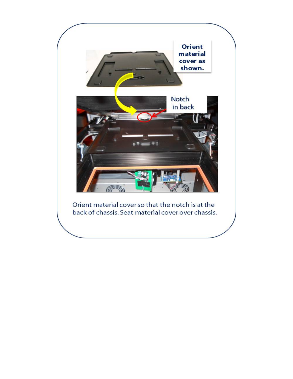
1.6.4.3 06.4.3 Material Tray Cover Installation . . . . . . . . . . . . . . . . . . . . . . . . . . . . . . . . . . . . . . . . . . . . . . . . . . . . . . . . . . . . . 47
1.6.4.4 06.4.4 Material Tray Gasket Installation . . . . . . . . . . . . . . . . . . . . . . . . . . . . . . . . . . . . . . . . . . . . . . . . . . . . . . . . . . . . 49
1.6.4.5 06.4.5 Material Tray Installation Instructions . . . . . . . . . . . . . . . . . . . . . . . . . . . . . . . . . . . . . . . . . . . . . . . . . . . . . . . . . 50
1.6.4.6 06.4.6 Coater, Scraper Bar Installation . . . . . . . . . . . . . . . . . . . . . . . . . . . . . . . . . . . . . . . . . . . . . . . . . . . . . . . . . . . . . 51
1.6.4.7 06.4.7 Material Cartridge Installation . . . . . . . . . . . . . . . . . . . . . . . . . . . . . . . . . . . . . . . . . . . . . . . . . . . . . . . . . . . . . . . 52
1.6.4.8 06.4.8 Resin Blotter Installation . . . . . . . . . . . . . . . . . . . . . . . . . . . . . . . . . . . . . . . . . . . . . . . . . . . . . . . . . . . . . . . . . . . 53
1.6.4.9 06.4.9 Printer Preparation for Material Color Change . . . . . . . . . . . . . . . . . . . . . . . . . . . . . . . . . . . . . . . . . . . . . . . . . . 54
1.6.5 06.5 Network and System Setup . . . . . . . . . . . . . . . . . . . . . . . . . . . . . . . . . . . . . . . . . . . . . . . . . . . . . . . . . . . . . . . . . . . . . . . 58
1.6.5.1 06.5.1. Basic Printer Network Information . . . . . . . . . . . . . . . . . . . . . . . . . . . . . . . . . . . . . . . . . . . . . . . . . . . . . . . . . . . 59
1.6.5.2 06.5.2 Network Setup for Online Printer Registration . . . . . . . . . . . . . . . . . . . . . . . . . . . . . . . . . . . . . . . . . . . . . . . . . . 60
1.6.5.3 06.5.3 Network Setup for Offline Printer Registration . . . . . . . . . . . . . . . . . . . . . . . . . . . . . . . . . . . . . . . . . . . . . . . . . . 61
1.6.5.4 06.5.4 Printer Network Configuration & User Profile . . . . . . . . . . . . . . . . . . . . . . . . . . . . . . . . . . . . . . . . . . . . . . . . . . . 63
1.6.5.5 06.5.5 User ID and Password . . . . . . . . . . . . . . . . . . . . . . . . . . . . . . . . . . . . . . . . . . . . . . . . . . . . . . . . . . . . . . . . . . . . 64
1.6.5.6 06.5.6 Print Preview Installation . . . . . . . . . . . . . . . . . . . . . . . . . . . . . . . . . . . . . . . . . . . . . . . . . . . . . . . . . . . . . . . . . . 65
1.6.5.7 06.5.7 Update Software . . . . . . . . . . . . . . . . . . . . . . . . . . . . . . . . . . . . . . . . . . . . . . . . . . . . . . . . . . . . . . . . . . . . . . . . . 66
1.7 07. ProJet™ Client Software Overview . . . . . . . . . . . . . . . . . . . . . . . . . . . . . . . . . . . . . . . . . . . . . . . . . . . . . . . . . . . . . . . . . . . . . . . 67
1.7.1 Alerts . . . . . . . . . . . . . . . . . . . . . . . . . . . . . . . . . . . . . . . . . . . . . . . . . . . . . . . . . . . . . . . . . . . . . . . . . . . . . . . . . . . . . . . . . . . . 68
1.7.2 Create New Print . . . . . . . . . . . . . . . . . . . . . . . . . . . . . . . . . . . . . . . . . . . . . . . . . . . . . . . . . . . . . . . . . . . . . . . . . . . . . . . . . . . 69
1.7.3 Diagnostics . . . . . . . . . . . . . . . . . . . . . . . . . . . . . . . . . . . . . . . . . . . . . . . . . . . . . . . . . . . . . . . . . . . . . . . . . . . . . . . . . . . . . . . 70
1.7.3.1 Current Status . . . . . . . . . . . . . . . . . . . . . . . . . . . . . . . . . . . . . . . . . . . . . . . . . . . . . . . . . . . . . . . . . . . . . . . . . . . . . . . . 71
1.7.3.2 Elevator Motion . . . . . . . . . . . . . . . . . . . . . . . . . . . . . . . . . . . . . . . . . . . . . . . . . . . . . . . . . . . . . . . . . . . . . . . . . . . . . . . 72
1.7.3.3 Routines . . . . . . . . . . . . . . . . . . . . . . . . . . . . . . . . . . . . . . . . . . . . . . . . . . . . . . . . . . . . . . . . . . . . . . . . . . . . . . . . . . . . . 73
1.7.3.4 Sensors and Output . . . . . . . . . . . . . . . . . . . . . . . . . . . . . . . . . . . . . . . . . . . . . . . . . . . . . . . . . . . . . . . . . . . . . . . . . . . . 74
1.7.3.5 Shuttle Motion . . . . . . . . . . . . . . . . . . . . . . . . . . . . . . . . . . . . . . . . . . . . . . . . . . . . . . . . . . . . . . . . . . . . . . . . . . . . . . . . 76
1.7.3.6 UV Shutter Motion . . . . . . . . . . . . . . . . . . . . . . . . . . . . . . . . . . . . . . . . . . . . . . . . . . . . . . . . . . . . . . . . . . . . . . . . . . . . . 77
1.7.4 Email Settings . . . . . . . . . . . . . . . . . . . . . . . . . . . . . . . . . . . . . . . . . . . . . . . . . . . . . . . . . . . . . . . . . . . . . . . . . . . . . . . . . . . . . 78
1.7.5 Help . . . . . . . . . . . . . . . . . . . . . . . . . . . . . . . . . . . . . . . . . . . . . . . . . . . . . . . . . . . . . . . . . . . . . . . . . . . . . . . . . . . . . . . . . . . . . 79
1.7.6 Home Page . . . . . . . . . . . . . . . . . . . . . . . . . . . . . . . . . . . . . . . . . . . . . . . . . . . . . . . . . . . . . . . . . . . . . . . . . . . . . . . . . . . . . . . 80
1.7.7 Network Identification Settings . . . . . . . . . . . . . . . . . . . . . . . . . . . . . . . . . . . . . . . . . . . . . . . . . . . . . . . . . . . . . . . . . . . . . . . . 81
1.7.8 Printer ON-OFF . . . . . . . . . . . . . . . . . . . . . . . . . . . . . . . . . . . . . . . . . . . . . . . . . . . . . . . . . . . . . . . . . . . . . . . . . . . . . . . . . . . . 82
1.7.9 Printer User Account . . . . . . . . . . . . . . . . . . . . . . . . . . . . . . . . . . . . . . . . . . . . . . . . . . . . . . . . . . . . . . . . . . . . . . . . . . . . . . . . 83
1.7.10 Prints Queue . . . . . . . . . . . . . . . . . . . . . . . . . . . . . . . . . . . . . . . . . . . . . . . . . . . . . . . . . . . . . . . . . . . . . . . . . . . . . . . . . . . . . 84
1.7.11 Print Tracking (TSV Report) . . . . . . . . . . . . . . . . . . . . . . . . . . . . . . . . . . . . . . . . . . . . . . . . . . . . . . . . . . . . . . . . . . . . . . . . . 85
1.7.12 Software Updates . . . . . . . . . . . . . . . . . . . . . . . . . . . . . . . . . . . . . . . . . . . . . . . . . . . . . . . . . . . . . . . . . . . . . . . . . . . . . . . . . 86
1.8 08. Operations . . . . . . . . . . . . . . . . . . . . . . . . . . . . . . . . . . . . . . . . . . . . . . . . . . . . . . . . . . . . . . . . . . . . . . . . . . . . . . . . . . . . . . . . . . 87
1.8.1 08.1 Print Process & Previewing Print . . . . . . . . . . . . . . . . . . . . . . . . . . . . . . . . . . . . . . . . . . . . . . . . . . . . . . . . . . . . . . . . . . . 89
Page 2

1.8.1.1 08.1.01 Create a New Print . . . . . . . . . . . . . . . . . . . . . . . . . . . . . . . . . . . . . . . . . . . . . . . . . . . . . . . . . . . . . . . . . . . . . . 90
1.8.1.2 08.1.02 Submitting a Print to Print Preview . . . . . . . . . . . . . . . . . . . . . . . . . . . . . . . . . . . . . . . . . . . . . . . . . . . . . . . . . . 91
1.8.1.3 08.1.03 Previewing Prints . . . . . . . . . . . . . . . . . . . . . . . . . . . . . . . . . . . . . . . . . . . . . . . . . . . . . . . . . . . . . . . . . . . . . . . 93
1.8.1.3.1 8.1.03.1 Print Preview . . . . . . . . . . . . . . . . . . . . . . . . . . . . . . . . . . . . . . . . . . . . . . . . . . . . . . . . . . . . . . . . . . . . . 94
1.8.1.3.2 8.1.03.2 Preview Browser Overview . . . . . . . . . . . . . . . . . . . . . . . . . . . . . . . . . . . . . . . . . . . . . . . . . . . . . . . . . . 99
1.8.1.4 08.1.04 Save a Print . . . . . . . . . . . . . . . . . . . . . . . . . . . . . . . . . . . . . . . . . . . . . . . . . . . . . . . . . . . . . . . . . . . . . . . . . . . 141
1.8.2 08.2. Delete a Print . . . . . . . . . . . . . . . . . . . . . . . . . . . . . . . . . . . . . . . . . . . . . . . . . . . . . . . . . . . . . . . . . . . . . . . . . . . . . . . . . 142
1.8.3 08.3. Part Removal & Cleaning Procedure . . . . . . . . . . . . . . . . . . . . . . . . . . . . . . . . . . . . . . . . . . . . . . . . . . . . . . . . . . . . . . . 143
1.8.4 08.4. Shutting Down System . . . . . . . . . . . . . . . . . . . . . . . . . . . . . . . . . . . . . . . . . . . . . . . . . . . . . . . . . . . . . . . . . . . . . . . . . . 144
1.8.5 08.5. Alert Messages . . . . . . . . . . . . . . . . . . . . . . . . . . . . . . . . . . . . . . . . . . . . . . . . . . . . . . . . . . . . . . . . . . . . . . . . . . . . . . . . 145
1.8.5.1 Cartridge Alerts . . . . . . . . . . . . . . . . . . . . . . . . . . . . . . . . . . . . . . . . . . . . . . . . . . . . . . . . . . . . . . . . . . . . . . . . . . . . . . . 146
1.8.5.1.1 Cartridge Empty . . . . . . . . . . . . . . . . . . . . . . . . . . . . . . . . . . . . . . . . . . . . . . . . . . . . . . . . . . . . . . . . . . . . . . . . . . 147
1.8.5.1.2 Cartridge Low . . . . . . . . . . . . . . . . . . . . . . . . . . . . . . . . . . . . . . . . . . . . . . . . . . . . . . . . . . . . . . . . . . . . . . . . . . . . 148
1.8.5.1.3 Cartridge Very Low . . . . . . . . . . . . . . . . . . . . . . . . . . . . . . . . . . . . . . . . . . . . . . . . . . . . . . . . . . . . . . . . . . . . . . . 149
1.8.5.2 Imager Alerts . . . . . . . . . . . . . . . . . . . . . . . . . . . . . . . . . . . . . . . . . . . . . . . . . . . . . . . . . . . . . . . . . . . . . . . . . . . . . . . . . 150
1.8.5.2.1 Imager output is Low . . . . . . . . . . . . . . . . . . . . . . . . . . . . . . . . . . . . . . . . . . . . . . . . . . . . . . . . . . . . . . . . . . . . . . 151
1.8.5.3 Print Alerts . . . . . . . . . . . . . . . . . . . . . . . . . . . . . . . . . . . . . . . . . . . . . . . . . . . . . . . . . . . . . . . . . . . . . . . . . . . . . . . . . . . 152
1.8.5.3.1 Print Aborted . . . . . . . . . . . . . . . . . . . . . . . . . . . . . . . . . . . . . . . . . . . . . . . . . . . . . . . . . . . . . . . . . . . . . . . . . . . . 153
1.8.5.3.2 Print Complete . . . . . . . . . . . . . . . . . . . . . . . . . . . . . . . . . . . . . . . . . . . . . . . . . . . . . . . . . . . . . . . . . . . . . . . . . . . 154
1.8.6 08.6 Printer LED Status Lights . . . . . . . . . . . . . . . . . . . . . . . . . . . . . . . . . . . . . . . . . . . . . . . . . . . . . . . . . . . . . . . . . . . . . . . . 155
1.8.6.1 08.6.01 User Interface Control Panel LED Operation . . . . . . . . . . . . . . . . . . . . . . . . . . . . . . . . . . . . . . . . . . . . . . . . . . 156
1.9 09. Maintenance . . . . . . . . . . . . . . . . . . . . . . . . . . . . . . . . . . . . . . . . . . . . . . . . . . . . . . . . . . . . . . . . . . . . . . . . . . . . . . . . . . . . . . . . 157
1.9.1 3. Cleaning Image Mirrors . . . . . . . . . . . . . . . . . . . . . . . . . . . . . . . . . . . . . . . . . . . . . . . . . . . . . . . . . . . . . . . . . . . . . . . . . . . . 158
1.9.2 1. Clean Image Plane & Material Trap . . . . . . . . . . . . . . . . . . . . . . . . . . . . . . . . . . . . . . . . . . . . . . . . . . . . . . . . . . . . . . . . . . 159
1.9.3 2. Cleaning Outer Surfaces . . . . . . . . . . . . . . . . . . . . . . . . . . . . . . . . . . . . . . . . . . . . . . . . . . . . . . . . . . . . . . . . . . . . . . . . . . . 160
1.9.4 5. Preventative Maintenance Check List . . . . . . . . . . . . . . . . . . . . . . . . . . . . . . . . . . . . . . . . . . . . . . . . . . . . . . . . . . . . . . . . . 161
1.9.5 4. Air Filter Replacement . . . . . . . . . . . . . . . . . . . . . . . . . . . . . . . . . . . . . . . . . . . . . . . . . . . . . . . . . . . . . . . . . . . . . . . . . . . . . 162
1.9.6 6. Replacement Parts . . . . . . . . . . . . . . . . . . . . . . . . . . . . . . . . . . . . . . . . . . . . . . . . . . . . . . . . . . . . . . . . . . . . . . . . . . . . . . . 163
1.9.7 7. Returning Printer for Repair . . . . . . . . . . . . . . . . . . . . . . . . . . . . . . . . . . . . . . . . . . . . . . . . . . . . . . . . . . . . . . . . . . . . . . . . 164
1.10 10. Error Messages . . . . . . . . . . . . . . . . . . . . . . . . . . . . . . . . . . . . . . . . . . . . . . . . . . . . . . . . . . . . . . . . . . . . . . . . . . . . . . . . . . . . . 165
1.10.1 Elevator Error Messages . . . . . . . . . . . . . . . . . . . . . . . . . . . . . . . . . . . . . . . . . . . . . . . . . . . . . . . . . . . . . . . . . . . . . . . . . . . . 166
1.10.2 Imager Error Messages . . . . . . . . . . . . . . . . . . . . . . . . . . . . . . . . . . . . . . . . . . . . . . . . . . . . . . . . . . . . . . . . . . . . . . . . . . . . . 167
1.10.3 Material Cartridge Error Messages . . . . . . . . . . . . . . . . . . . . . . . . . . . . . . . . . . . . . . . . . . . . . . . . . . . . . . . . . . . . . . . . . . . . 168
1.10.4 Shuttle Error Messages . . . . . . . . . . . . . . . . . . . . . . . . . . . . . . . . . . . . . . . . . . . . . . . . . . . . . . . . . . . . . . . . . . . . . . . . . . . . . 169
1.11 11. Troubleshooting . . . . . . . . . . . . . . . . . . . . . . . . . . . . . . . . . . . . . . . . . . . . . . . . . . . . . . . . . . . . . . . . . . . . . . . . . . . . . . . . . . . . 170
1.11.1 Printer Hardware . . . . . . . . . . . . . . . . . . . . . . . . . . . . . . . . . . . . . . . . . . . . . . . . . . . . . . . . . . . . . . . . . . . . . . . . . . . . . . . . . . 171
1.11.2 User Diagnostics . . . . . . . . . . . . . . . . . . . . . . . . . . . . . . . . . . . . . . . . . . . . . . . . . . . . . . . . . . . . . . . . . . . . . . . . . . . . . . . . . . 172
1.11.2.1 Material Tray Cure Routine . . . . . . . . . . . . . . . . . . . . . . . . . . . . . . . . . . . . . . . . . . . . . . . . . . . . . . . . . . . . . . . . . . . . . 173
1.11.2.2 Perform Low Material Tray Fill . . . . . . . . . . . . . . . . . . . . . . . . . . . . . . . . . . . . . . . . . . . . . . . . . . . . . . . . . . . . . . . . . . . 178
1.11.2.3 Perform New Material Tray Fill . . . . . . . . . . . . . . . . . . . . . . . . . . . . . . . . . . . . . . . . . . . . . . . . . . . . . . . . . . . . . . . . . . 179
1.11.2.4 Perform Routine Maintenance . . . . . . . . . . . . . . . . . . . . . . . . . . . . . . . . . . . . . . . . . . . . . . . . . . . . . . . . . . . . . . . . . . . 180
1.11.2.5 Start Coat Test . . . . . . . . . . . . . . . . . . . . . . . . . . . . . . . . . . . . . . . . . . . . . . . . . . . . . . . . . . . . . . . . . . . . . . . . . . . . . . . 181
1.11.3 VisiJet® FTI Material . . . . . . . . . . . . . . . . . . . . . . . . . . . . . . . . . . . . . . . . . . . . . . . . . . . . . . . . . . . . . . . . . . . . . . . . . . . . . . . 182
1.12 12. Spare Parts Locator . . . . . . . . . . . . . . . . . . . . . . . . . . . . . . . . . . . . . . . . . . . . . . . . . . . . . . . . . . . . . . . . . . . . . . . . . . . . . . . . . 183
1.13 13. Other Documents . . . . . . . . . . . . . . . . . . . . . . . . . . . . . . . . . . . . . . . . . . . . . . . . . . . . . . . . . . . . . . . . . . . . . . . . . . . . . . . . . . . 184
1.13.1 ProJet™ 1000 & 1500 Quick Reference Guide . . . . . . . . . . . . . . . . . . . . . . . . . . . . . . . . . . . . . . . . . . . . . . . . . . . . . . . . . . . 185
1.13.2 ProJet™ Parts Finishing Systems User Guide . . . . . . . . . . . . . . . . . . . . . . . . . . . . . . . . . . . . . . . . . . . . . . . . . . . . . . . . . . . 186
1.13.3 VisiJet® FTI Material Safety Data Sheet (MSDS & SDS) . . . . . . . . . . . . . . . . . . . . . . . . . . . . . . . . . . . . . . . . . . . . . . . . . . . 187
1.14 14. Service & Support . . . . . . . . . . . . . . . . . . . . . . . . . . . . . . . . . . . . . . . . . . . . . . . . . . . . . . . . . . . . . . . . . . . . . . . . . . . . . . . . . . . 188
1.14.1 Contacts . . . . . . . . . . . . . . . . . . . . . . . . . . . . . . . . . . . . . . . . . . . . . . . . . . . . . . . . . . . . . . . . . . . . . . . . . . . . . . . . . . . . . . . . 189
1.14.2 How To Order Parts . . . . . . . . . . . . . . . . . . . . . . . . . . . . . . . . . . . . . . . . . . . . . . . . . . . . . . . . . . . . . . . . . . . . . . . . . . . . . . . 190
1.14.3 Service Support . . . . . . . . . . . . . . . . . . . . . . . . . . . . . . . . . . . . . . . . . . . . . . . . . . . . . . . . . . . . . . . . . . . . . . . . . . . . . . . . . . . 191
1.15 15. Online Help . . . . . . . . . . . . . . . . . . . . . . . . . . . . . . . . . . . . . . . . . . . . . . . . . . . . . . . . . . . . . . . . . . . . . . . . . . . . . . . . . . . . . . . . 192
1.15.1 Frequently Ask Questions (FAQ) . . . . . . . . . . . . . . . . . . . . . . . . . . . . . . . . . . . . . . . . . . . . . . . . . . . . . . . . . . . . . . . . . . . . . 193
1.15.2 Getting Help . . . . . . . . . . . . . . . . . . . . . . . . . . . . . . . . . . . . . . . . . . . . . . . . . . . . . . . . . . . . . . . . . . . . . . . . . . . . . . . . . . . . . 195
1.16 16. Glossary Of Terms . . . . . . . . . . . . . . . . . . . . . . . . . . . . . . . . . . . . . . . . . . . . . . . . . . . . . . . . . . . . . . . . . . . . . . . . . . . . . . . . . . 196
1.17 17. Index . . . . . . . . . . . . . . . . . . . . . . . . . . . . . . . . . . . . . . . . . . . . . . . . . . . . . . . . . . . . . . . . . . . . . . . . . . . . . . . . . . . . . . . . . . . . . 197
Page 3

ProJet™ 1000 & 1500 Table of Contents
01. Introduction
About This Guide
Copyright
Features & Benefits
02. Safety Symbols & Definitions
03. Safety Guidelines
General Safety Guidelines
Printer Safety Guidelines
Visi-Jet® FTI Material Safety Guidelines
04. System Requirements
Client's Computer & Network Interface
Electrical
Operating Environment & Workspace
ProJet™ 1000 & 1500 Printer Dimensions
Space Requirements
VisiJet® FTI Material Cartridges
05. Familiarization
System Operation
System Overview
06. Printer Installation
06.1 What is Included with the Printer
06.2 Uncrating Printer
06.3 Leveling Printer
06.4 Printer Preparation
06.5 Network and System Setup
07. ProJet™ Client Software Overview
Alerts
Create New Print
Diagnostics
Email Settings
Help
Home Page
Network Identification Settings
Printer ON-OFF
Printer User Account
Prints Queue
Print Tracking (TSV Report)
Software Updates
08. Operations
Page 4

08.1 Print Process & Previewing Print
08.2. Delete a Print
08.3. Part Removal & Cleaning Procedure
08.4. Shutting Down System
08.5. Alert Messages
08.6 Printer LED Status Lights
09. Maintenance
1. Clean Image Plane & Material Trap
2. Cleaning Outer Surfaces
3. Cleaning Image Mirrors
4. Air Filter Replacement
5. Preventative Maintenance Check List
6. Replacement Parts
7. Returning Printer for Repair
10. Error Messages
Elevator Error Messages
Imager Error Messages
Material Cartridge Error Messages
Shuttle Error Messages
11. Troubleshooting
Printer Hardware
User Diagnostics
VisiJet® FTI Material
12. Spare Parts Locator
13. Other Documents
ProJet™ 1000 & 1500 Quick Reference Guide
ProJet™ Parts Finishing Systems User Guide
VisiJet® FTI Material Safety Data Sheet (MSDS & SDS)
14. Service & Support
Contacts
How To Order Parts
Service Support
15. Online Help
Frequently Ask Questions (FAQ)
Getting Help
16. Glossary Of Terms
17. Index
Page 5
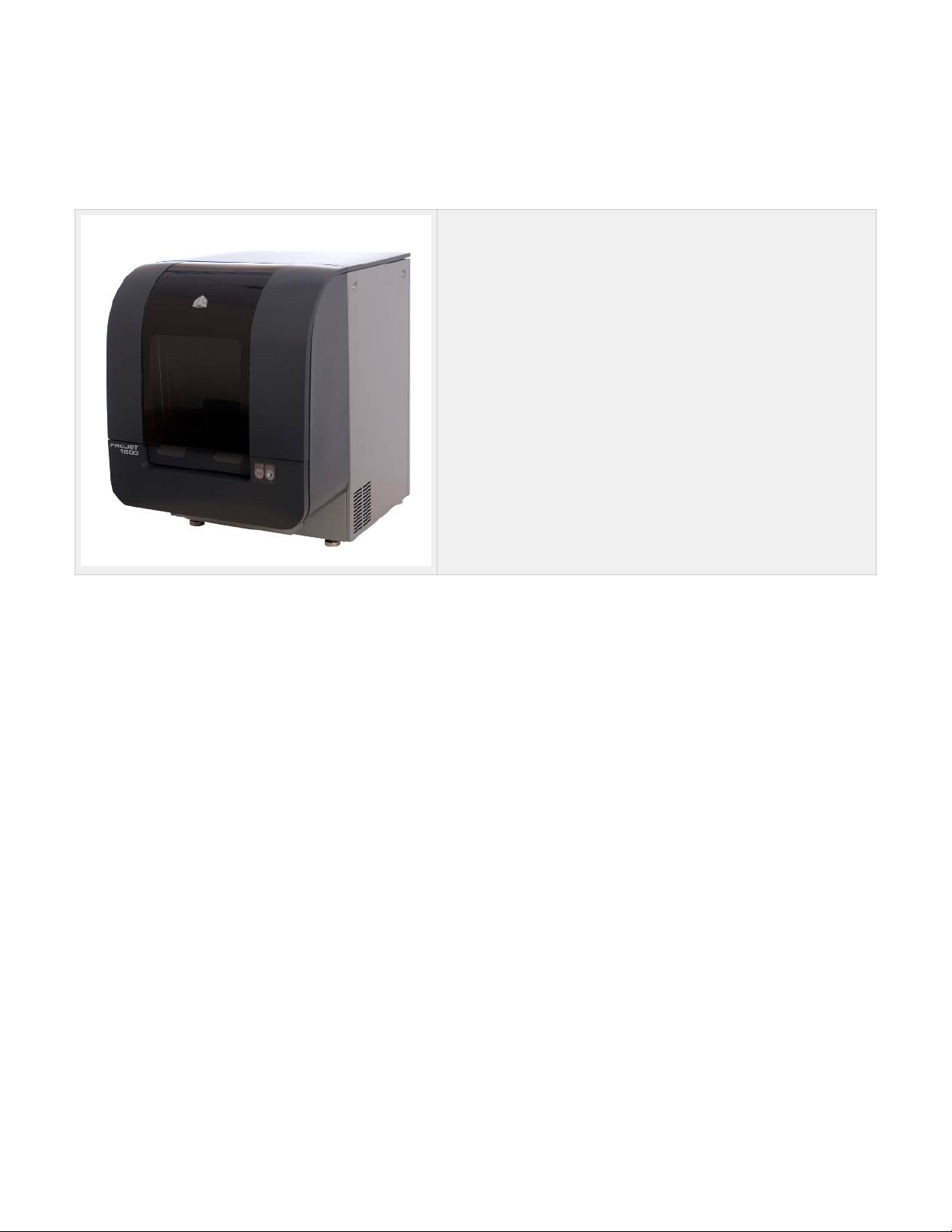
01. Introduction
3D Systems would like to congratulate you on the purchase of your 3-D personal printing system. We take pride in our ability to offer our
customers the latest in three dimensional and idea printing solutions. The 3D System team is confident that your system will provide many years
of valuable service.
This user guide will provide information in how to get the best
performance from your Projet 1000 / 1500 system.
About This Guide
Copyright
Features & Benefits
Page 6

About This Guide
This guide is created to give you an understanding of key features, system requirements and operating procedures for your ProJet™ 1000 / 1500
Personal Printer. Click on the links which will lead you to the section of choice.
For support documentation, see . To order material cartridges or parts, please contact your Authorized reseller or contact Other Documents 3D
to locate your nearest Authorized Reseller. Read and understand all safety guidelines beforeSystems Customer Support Safety Guidelines:
attempting to operate your printer. These guidelines provide important details on how to handle the VisiJet® material cartridge properly and also
describe how to avoid personal injury and/or damage to the printer. For more detailed information on material safety, see VisiJet® Material
Guidelines.
System Requirements: This section provides all the necessary facility requirements for electrical, hardware, dimensional and
environmental data.
Familiarization: A pictorial view and description of printer functions and controls.
System Installation: Describes how to install the printer and 3dpedia browser. Once installed, the user can build a test print to ensure
the installation and the print process was successful.
Operations: Describes functionality and the build process when starting a new or an existing design.
Error Messages: Flow chart describing the reason for printer's error message, what cause the error and the solution.
Maintenance: Provides detail information when performing software, hardware and preventative maintenance to the printer.
Troubleshooting: Describes how to diagnose problems pertaining to the printer's hardware and software.
Spare Parts Locator: Quick access to parts that can be order through 3D Systems Customer Support.
Other Documents: The Warranty and Maintenance Agreements information, along with the Material Safety Data Sheet (MSDS/SDS).
Support: 3D Systems Customer Support will provide you information on how to obtain software updates; how to order parts and return
parts through 3D Systems' Return Material Agreement (RMA). Information on how to get system upgrades and updates.
Help: Quick access to answers to frequently asked questions (FAQ).
Glossary of Terms: Alphabetical listing of terms that are frequently used through ProJet® 1000 / 1500 User Guide and their description.
Index: Listing in alphabetical order for quick reference when you are uncertain of the section the term may be used in the guide.
Page 7

Copyright
© 2011 by 3D Systems®, All rights reserved.
Under the copyright laws, this user guide may not be copied, in whole or in part, without the written consent of 3D Systems. The ProJet™ logo is
a trademark of 3D Systems® and is registered in the U.S. Use of this logo without the prior written consent of 3D Systems® may constitute
trademark infringement and unfair competition in violation of federal and state laws.
Every effort has been made to ensure that the information in this manual is accurate. Other company and product names mentioned herein are
trademarks of their respective companies. Mention of third-party products is for informational purposes only and constitutes neither an
endorsement nor a recommendation.
The product described in this user guide incorporates copyright protection technology that is protected by method claims of certain U.S. and
foreign patents and other intellectual property rights that are owned by 3D Systems®. Reverse engineering is prohibited.
VisiJet® is a registered trademark of 3D Systems®.
ProJet™ 1000 / 1500 Personal 3D Printer produces plastic prototype parts from 3-D solid Computer-Aided Design (CAD) models. It is intended to
be used as a 3-dimensional output device to communicate design intent with durable, physical parts. Parts produced can be used in all phases of
design, from a concept build to functional testing and assembly verification. For example, a part can be used as a tool to communicate design
intent, to verify the fit of a new or existing component part or to create a rugged, plastic prototype of a new invention.
These parts are generated in the rapid prototyping (RP) environment under the control of the printer operators. It does not require a special
technical staff to supervise the system. All design and process considerations are compatible with an RP environment. The three-dimensional
solid parts that are printed consist of an ultraviolet (UV) curable material. The resin transfer mechanism provides a controlled layer thickness of
VisiJet® part material which is deposited and patterned using a proprietary imager technology which 3D Systems® has developed. When creating
the pattern, the VisiJet® material undergoes a phase change. This phase change converts the liquid material into a solid polymer. When the print
is complete, the part adheres to the print pad. This pad along with the part is removed from the print platform and the part is cleaned and cured to
provide a finished part.
Page 8
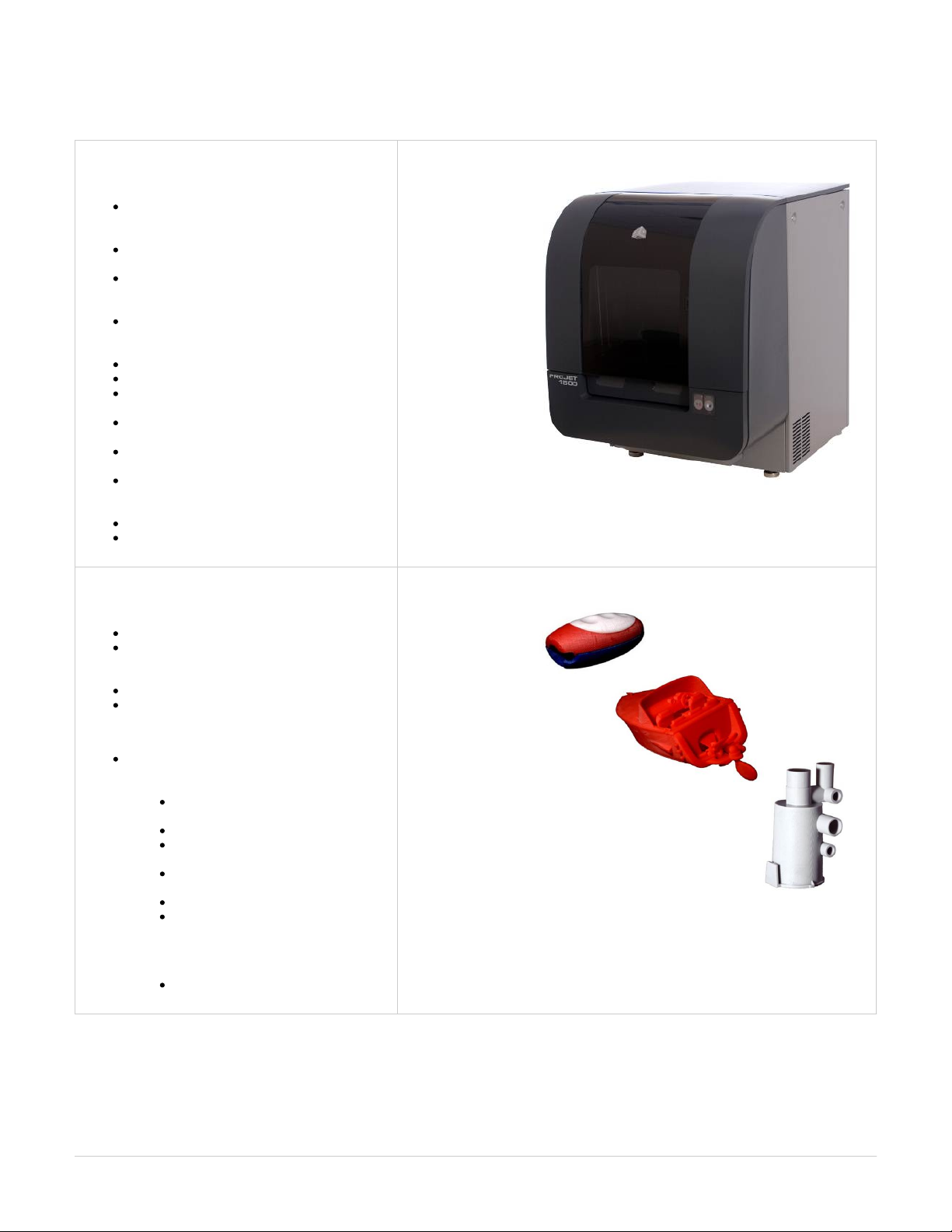
Features & Benefits
Personal 3D Printer
Simple mechanical design using few moving
parts. Increases reliability and decreases
manufacturing complexity.
Easily removable side panels for access to
inside compartment for maintenance.
Simple removable print pad platform. Parts are
cleaned on platform to reduce handling by the
user.
Maintenance and parts replacement can be
easily reached when replacing the imager bulb,
filters, and cleaning the imaging mirror.
Native Resolution (xy) - DPI- 1024 x 768 DPI
Standard Mode 0.004 in (102 µm);
ProJet 1500 Only: High speed Mode 0.006 in
(152 µm)
ProJet 1500 Max Build Size (XYZ) 6.75 x 9 x
8 in (171 x 228 x 203 mm)
ProJet 1000 Max Build Size (XYZ) 6.75 x 8 x
7 in (171 x 203 x 178 mm)
Vertical Build Speed Standard Mode 0.5
in/hour; High speed Mode 0.8 in/hour (VisiJet®
FTI-Zoom material only)
Min Feature Size 0.010 in (0.254 mm)
Min Vertical Wall Thickness - 0.025'
Material
Closed, self-contained
Cartridge communicates remaining material
quantity...partial cartridges can be removed and
reloaded for later print jobs
Cartridges may be changed during a print job
Consult your local regulations for disposal
ProJet 1500 Only- Material Color Choice:
Capable of building with 6-different materials.
All materials have low distortion properties, and
have a plastic like appearance.
Visijet® FTI-Zoom- for high speed and
draft capability
Visijet® FTI-Ivory- all purpose material
Visijet® FTI-Grey- great for showing
detail in parts
Visijet® FTI-Black- consistent opacity
black material
Visijet® FTI-Blue- deep blue material
Visijet® FTI-Red- bright red great for
detail and surface quality
ProJet 1000 Only- Material Choice:
Visijet® FTI-Ivory- all purpose material
Page 9
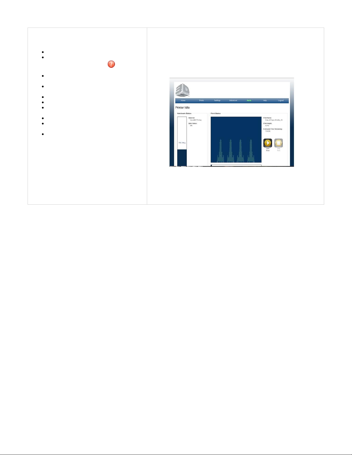
Software
Easy set-up - software pre-loaded on 3D printer
Get help during the printing operation is by
clicking on the question mark at the right
corner of software screens
Print Preview provides Tips on how to
manipulate the part for ultimate part placement
3D printer warranty activation at the initial
system registration
Easy STL, CTL file loading
Easy job preparation and submission
Automatic and manual part alignment on build
platform
Automatic part support generation
Part support can be generated manually to add
supports where needed
STL file verification
Page 10
02. Safety Symbols & Definitions
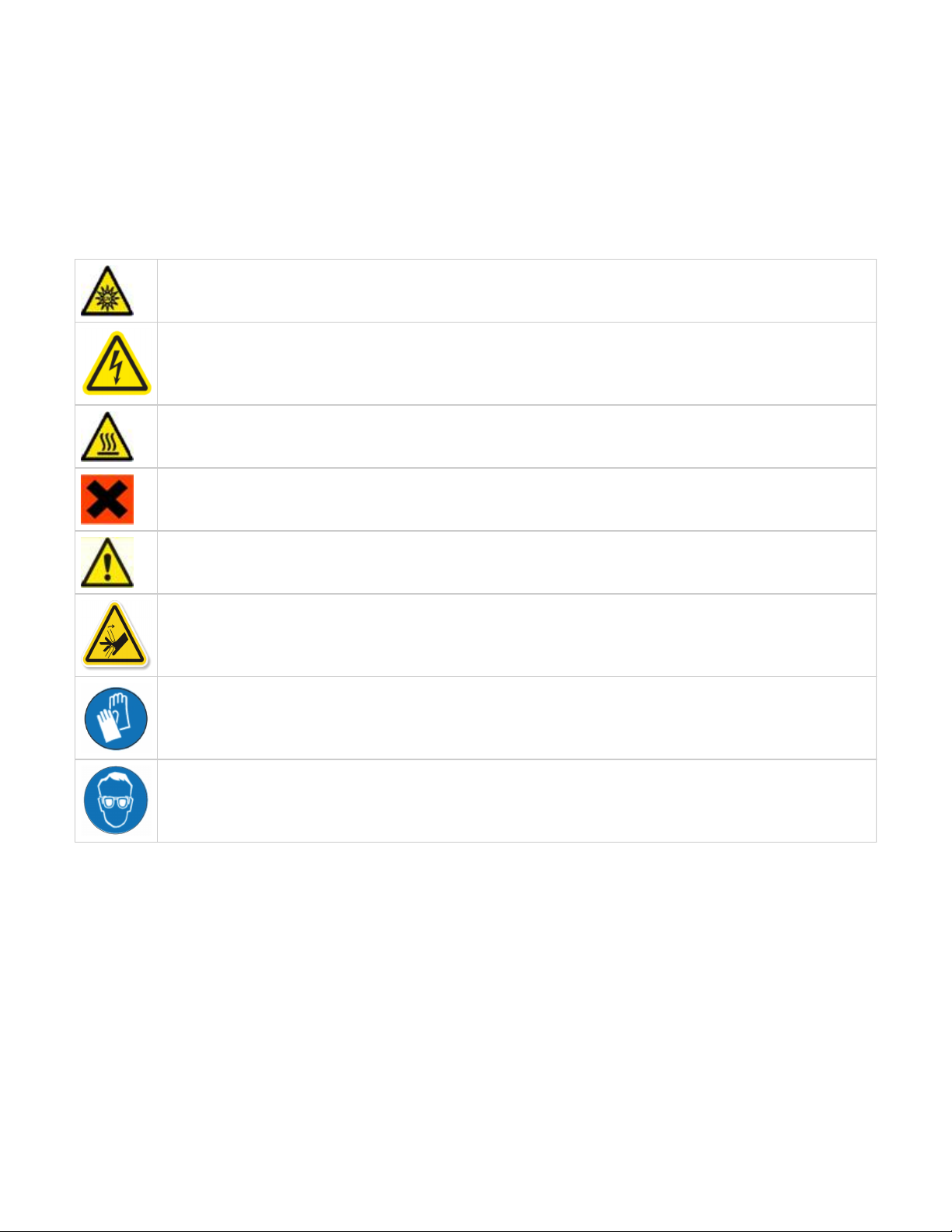
Various symbols are used in this guide, the user's manual and on the product itself to ensure correct usage, to prevent danger to the
user and others, and to prevent property damage. The meanings of these symbols are described below.
It is important that you read these descriptions thoroughly and fully understand the contents.
UV Radiation Hazard: Invisible UV radiation is accessible in the vicinity of this sign or behind the panel. Radiation can cause
eye injury. Access panels are for service only and should be opened only by certified service personnel.
Electrical Shock Hazard: High voltage electricity is accessible in the vicinity of this sign or behind the access panel. High
voltage can cause severe burns or death. Access panels are for service only and should be opened only by certified service
personnel or trained maintenance personnel.
Hot Surface Hazard: A hot surface is accessible in the vicinity of this sign or behind the access panel. Avoid contact. Hot
surfaces can cause severe burns. Access panels are for service only and should be opened only by certified service personnel
or trained maintenance personnel.
Harmful Irritant Warning: Indicates that skin or eye irritation could result while exposed to a chemical composition.
Caution: Indicates something may happen that could cause loss of data, damage to equipment, or personal injury.
Pinch Point: Indicates hands and/or fingers potentially could be pinched when interacting with the equipment.
Wear gloves when handling uncured VisiJet® build material.
Ultraviolet radiation inside. Exposure may cause eye damage. Do not operate without covers. Wear UV eye protection.
Page 11

03. Safety Guidelines
To ensure personal safety and to avoid damage to your printer, read and understand all safety guidelines in this section.
General Safety Guidelines
Printer Safety Guidelines
Visi-Jet® FTI Material Safety Guidelines
Page 12
General Safety Guidelines
3D Systems' number one priority is to . With that in mind, we want to ensure the safety of our customers andTake Care of our Customers
prevent unsafe operating conditions. One of the safety features in the ProJet™ 1000 / 1500 Personal 3D Printer, it will automatically shut down if
an unsafe condition is detected. However, improper use of the system could result in personal injury.
General Safety Guidelines
To ensure personal safety, follow these general safety guidelines when operating the printing system.
Follow all safety rules in this section and observe all cautions and warnings in this guide.
TO open the door during the printing cycle, press the pause/play button on the machine and then to press the unlock/lock button to open
the door. The system will automatically stop moving parts and then unlock once completely paused. It is only necessary to press the
pause bottom one (1) time then wait for the build cycle for that layer to complete. To resume, press the lock button and then press the
play button.
Do not use part materials without first reviewing its . Material Safety Data Sheet (MSDS & SDS)
To prevent tripping, ensure power and communication cables are located away from the walking path to the printing system.
If performing maintenance to this system, ensure step by step instructions are followed and safety precautions are heeded during the
procedure.
Operators of the printer should be trained to perform necessary tasks when printing a part according to the guidelines that are set forth in
this manual. This includes understanding and following the safety and regulatory guidelines.
Do not modify any safety features or make modifications to the printing system. Doing so is prohibited and voids warranty and contractual
agreements.
Use of part materials, print pads or parts other than genuine 3D Systems® ProJet™ 1000 / 1500 components may void warranty and
other contractual agreements.
To prevent potential skin-irritation and sensitization due to contact with the part material, follow all guidelines in Material Safety Data
Sheet (MSDS).
The weight of the printer is approximately 122 lbs. (55.3kg) uncrated and requires two people to lift it. Use standard lifting practices and
always lift with legs bent. Failure to do so could result in serious injury. 3D Systems accepts no liability in the event of back injury due to
the lifting of the printer.
Housekeeping
Protective Eye Wear & Clothing
Page 13

Housekeeping
Good housekeeping should be practiced in the work area. The user should clean off inside and outside of printer where material is present and
properly maintain the printer in order to prevent malfunctions during the print process. Dispose of towels that have been used during cleaning
according to your local regulatory guidelines.
Page 14

Protective Eye Wear & Clothing
In the unlikely event that you are exposed to ultraviolet rays from the unit, proper precautions must be taken. To ensure your safety, protective
eye wear and clothing are listed below:
Potential UV Exposure
Protective Equipment includes:
UV-blocking safety goggles
Lab coat (when performing )Maintenance Procedures
Page 15

Printer Safety Guidelines
High Voltage Potential & Electrical Safety
Shuttle Plate Pinch Point
Ultraviolet (UV) Safety
Page 16
High Voltage Potential & Electrical Safety
High
Voltage
Potential
If the electrical module is in need of repair, power down the modeler and unplug the power supply. Remove the side
panel, then loosen the 10-32 screw and pull out the electronics tray. This will give access to the PC and Ebox (see
Electric Module Assembly Installation Instructions). Do not remove the PC cover, doing so will void warranty and
contractual agreements.
Electrical
Safety
To operate the printer, the doors (front door and cartridge door on side) must be closed.
This printer requires a grounded, 1-phase electrical power source with a service rating of 100 to 240 VAC~,
50/60 Hz, 5 A (max.). For more detail information, see System Requirements
Double
Pole/Neutral
Fusing
A fuse is used in neutral of single-phase equipment with permanently connected or provided with a
non-reversible plug.
After operation of the fuse, parts of the equipment that remain energized might represent a hazard during
servicing.
Page 17
Shuttle Plate Pinch Point
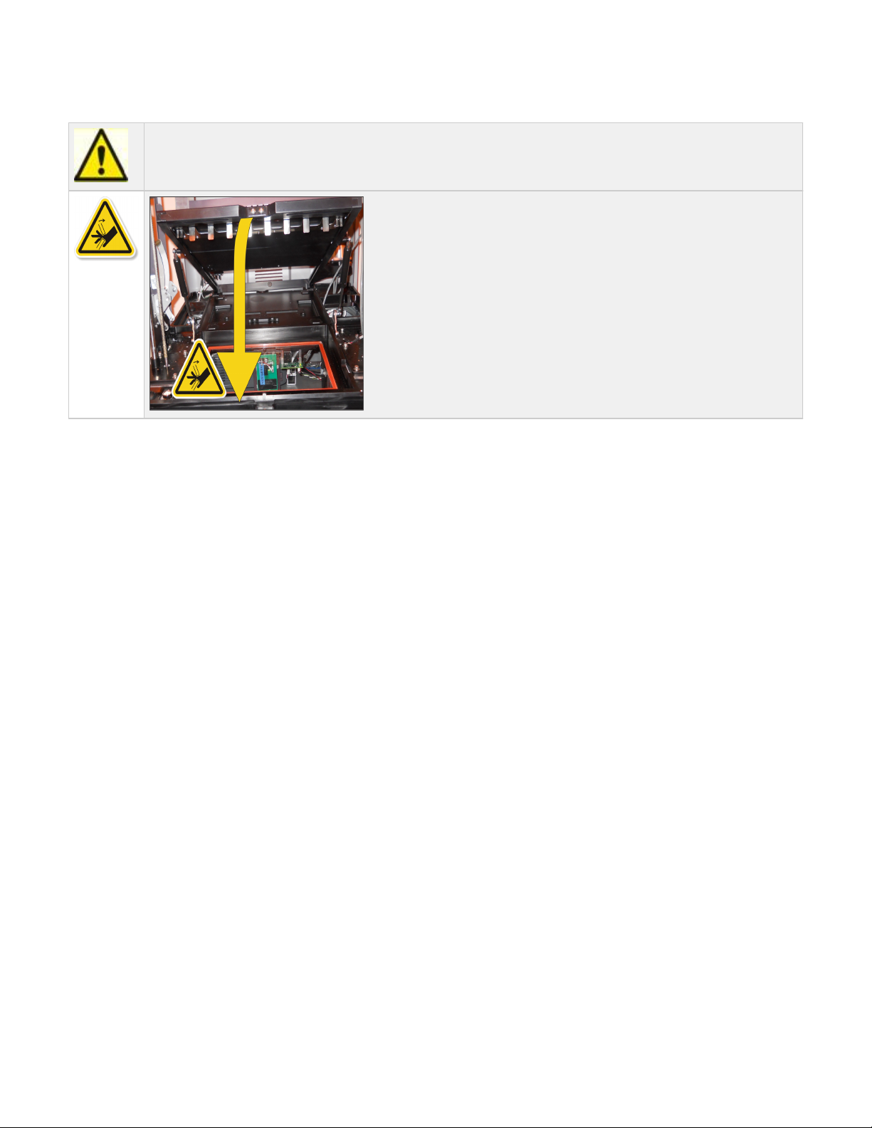
Caution: A pinch point exist between the shuttle plate and the frame. When closing the shuttle plate, keep fingers and
hands away from the pinch point area.
Page 18
Ultraviolet (UV) Safety
Ultraviolet (UV) Safety
In normal operation, the ultraviolet (UV) light is completely confined, so users are not exposed to potentially harmful emitted radiation.
UV light from the printer could cause personal injury. Use recommended protective eyewear which blocks the UV light. It is
recommended to never purposely stare directly into the printer during operation.
To prevent eye injury, do not open the door when the ultraviolet (UV) light is activated. When the door are closed, it keeps UV radiation
from escaping.
Pay attention and follow the warnings contained in this guide concerning operation and printer's maintenance procedures.
If the door is opened during operation, use the recommended protective eyewear which blocks the UV light.
Hazardous voltage exists inside the electrical module. Injury or death from electrical shock can result if system's electrical box covers
are removed. When installing replacement modules, ensure power is off before removing panels.
Page 19

Visi-Jet® FTI Material Safety Guidelines
VisiJet® FTI Material Cartridge Procedure
VisiJet ® FTI Material Cartridge Removal
VisiJet® FTI Material Disposal
VisiJet® FTI Material Handling
VisiJet® FTI Material Safety
VisiJet® FTI Material Usage
Page 20

VisiJet® FTI Material Cartridge Procedure
Uncured material waste is classified as regulated, and in some areas hazardous, thereby requiring special packaging, transportation and disposal.
Refer to your local local environmental regulatory agency.
Applicable material "waste" includes cartridges (empty or full). Any cleaning supplies used to clean up uncured material should be disposed of in
the same manner as the uncured material. To identify which disposal requirement applies, contact the local waste disposal service provider. (The
local environmental regulatory agency should have a list of qualified providers in your area.) Give the disposal service provider a copy of the
material's MSDS and the SNUR (Significant New Use Regulation - U.S. only). The service will provide a report, indicating the disposal
requirements that apply, as well as a quotation for regularly scheduled pickups.
3D Systems assumes no liability or responsibility for proper disposal of the uncured material. Proper disposal of the uncured material is the sole
responsibility of the user.
Page 21

VisiJet ® FTI Material Cartridge Removal
Wear protective gloves when removing print cartridge from the printer. Remove cartridge and place it in a disposal bag. Be
careful not to spill, drop or expose other materials to the waste.
Partially used cartridges should be returned to their original packaging to store for later use.
Page 22

VisiJet® FTI Material Disposal
ProJet™ 1000 / 1500 3-D Personal Printer operators should be informed about the potential hazards of part material prior to performing
operations which may result in exposure to uncured material. This includes removal and also, the disposal of empty cartridges or unlikely spills
that may occur during operation.
If leaks are present, it is an indication of a serious malfunction. The first priority is to protect users from inadvertently touching the material.
Handling uncured material requires the use of gloves and other protective equipment to ensure there is no direct skin contact. If uncured spills
occur, promptly remove the spilled material, and dispose of the waste material according to local environmental regulations.
If a problem with the printer occurs, discontinue use until the problem is diagnosed. Resolve the problem before continuing to operate the printer.
Small spills of uncured liquid can be cleaned up using disposable towels. After wiping the spill, wipe printer surfaces using a lint free cloth and
clean with Isopropyl alcohol or window cleaner.
Cleaning spills on carpeting can be difficult. Avoid placing printer over carpeted areas or use a barrier to avoid the possibility of carpet damage.
Advise any service provider involved (e.g. carpet cleaning service or disposal service) of the nature of the spilled material. Provide the MSDS and
other material information prior to their contact to the material. Provide material disposal requirements and cleaning solutions if the material is
uncured.
Tools that may be contaminated with the material should be cleaned prior to reuse.
Recommended solvents such as IPA are normally required to clean tools. A final wash with soap and water will remove any excess of print
material.
Page 23

VisiJet® FTI Material Handling
Upon receipt of the part material shipment, inspect the carton for signs of physical damage and evidence of leakage on the exterior. If leakage is
observed, do not open carton; immediately contact 3D Systems' Customer Support Hotline. If leakage is not present, store materials in their
material kits until they are ready to use. Materials should be kept indoors in a cool, dry area with adequate ventilation with temperatures between
16 °C (60 °F) and 27 °C (80 °F). DO NOT EXCEED A MAXIMUM STORAGE TEMPERATURE OF 35 °C (95 °F).
Keep materials away from direct sunlight, heat, flames and other direct light or UV energy sources. For optimal results, keep stored cartons
closed and sealed until the cartridge is ready for use. Authorized 3D Systems VisiJet® FTI Material should only be used in the printer.
Page 24

VisiJet® FTI Material Safety
Training: New users should be trained in the hazards and management of materials. Such training should be provided before they begin working
with the printer or disposal of material waste.
Once the print material has completed its printing cycle, the print needs to be removed, cleaned and cured, rendering it safe to handle. When print
material is uncured- meaning in a paste or wet form, do not touch uncured print material directly without protective gloves. If uncured material is
observed, follow the "Personal Protective Equipment and Skin Protection" to ensure the safe handling of uncured print material.
Flammability and Combustibility: Do not expose print material to heat (at or above 110°C/ 230°F), flames, sparks, or any source of ignition.
(Though the U.S. Department of Transportation does not consider this material a "flammability hazard," they do classify it as combustible based
on their flash points.) For more information on VisiJet® Material flash points and combustibility, see the packagedVisiJet® Material MSDS/SDS
with the material cartridge.
Health Hazards: Any chemical may exert harmful effects if it enters or contacts the body in sufficient quantities. Uncured material is a sensitizer,
and can cause allergic reactions if it comes in contact with the skin. Always wear chemically resistant protective gloves, nitrile or neoprene gloves
are recommended. DO NOT use latex gloves. Consult the MSDS for specific information about the sensitization potential.
Sensitization dermatitis is the result of an allergic reaction to a given substance. In some cases, direct skin contact is necessary to cause
sensitization. It is possible for individuals to become sensitized to a substance even after a trouble-free period of exposure. Many factors affect a
person's susceptibility including: existing skin conditions, personal habits, and individual sensitivity. Even slight exposure can sometimes trigger a
severe outbreak of dermatitis. Since sensitization is permanent, a sensitized individual should avoid further contact with the sensitizing agent.
Inhalation: Under normal operation, inhalation is not an expected exposure method. To ensure personal safety, uncured print material should not
be present where food and drink are stored, prepared or consumed. As a precaution, after handling material, wash hands with soap and water
before handling food. Finished parts (cured) can be handled or disposed of in the same manner as standard household plastic products. These
parts are not recyclable.
Exposure Control: The printer has a variety of built-in safety features that are designed to prevent operator exposure. Do not try to change or
disable these features.
Personal Protective Equipment and Skin Protection: Exposure to uncured material may occur when removing and disposing spent print
cartridges. To prevent contact, wear chemically resistant protective gloves - nitrile or neoprene gloves are recommended. Wear safety glasses
with side shields to provide eye protection in the event of a leak or spill of uncured print material.
Respiratory Protection: Because of the printer's built in controls, respiratory protection is not necessary during normal operation. The status
screen in the client software will prompt the user to change the printer's air filters at prescribed times. Individual use may vary depending on the
run time of the modeler. A NIOSH-approved (or equivalent) dust mask is recommended when dry sanding cured parts.
Page 25
VisiJet® FTI Material Usage
The VisiJet® Material "Best Used By" date is indicated on the material kit label. For best results, please use materials by the date indicated. When
the printer detects a "Best Used By" date has expired, the software will warn the user. For best results, material should be used before the date
indicated.
Before removing cartridge from its protective poly bag, and before loading it in to the printer, inspect the cartridge for signs of leakage
or physical damage. Do not load cartridge that is leaking or is damaged. Dispose of it according to your local regulations.
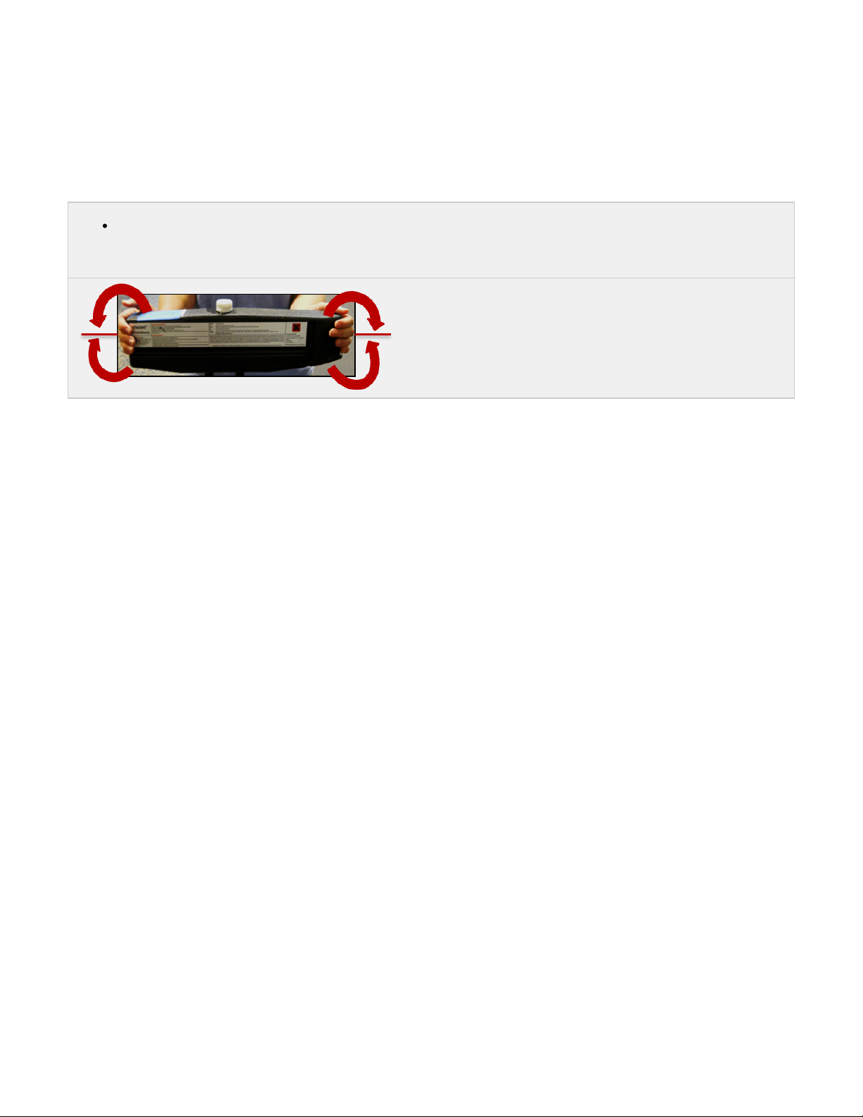
IMPORTANT: Before installation and if the cartridge has not been used for more than two weeks, shake material cartridge left, right
and then right, left motions for at least one (1) minute to ensure its contents are thoroughly mixed.
.
!
Page 26

04. System Requirements
Client's Computer & Network Interface
Electrical
Operating Environment & Workspace
ProJet™ 1000 & 1500 Printer Dimensions
Space Requirements
VisiJet® FTI Material Cartridges
Page 27

Client's Computer & Network Interface
The internal controller in this printer provides an integrated, 10/100 - megabit-per-second (Mbps) Ethernet network connection. This connection
supports both the 10 base-T and 100 base-TX Ethernet standards. The controller's connector is designed for attaching the Ethernet cable.
When a facility's internal network is not 10base-T or 100base-TX, a media converter, such as a Coax to 10base-T will be required. Consult with
the organization's network engineering or the IT Department to provide assistance with these requirements.
Network Specifications Minimum Recommendations
Hardware Interface
Ethernet network
Printer Control Software
Proprietary
Client Hardware Requirements
2.8 GHZ Pentium 4 or better, min. 1GB of RAM
Client Software System
Internet Explorer 8 and above, Firefox 6 and above, Chrome 10 and above
Input Data File Format
. STL, . CTL.
Page 28
Electrical
During normal operation, the power usage of the printer will not exceed the continuous current rating. Ensure that the power supply is at least 6
amps.
European-style circuit breaker or other protective equipment rated for lower levels of protection are not recommended, and risk damage to the
unit's internal electronic components.
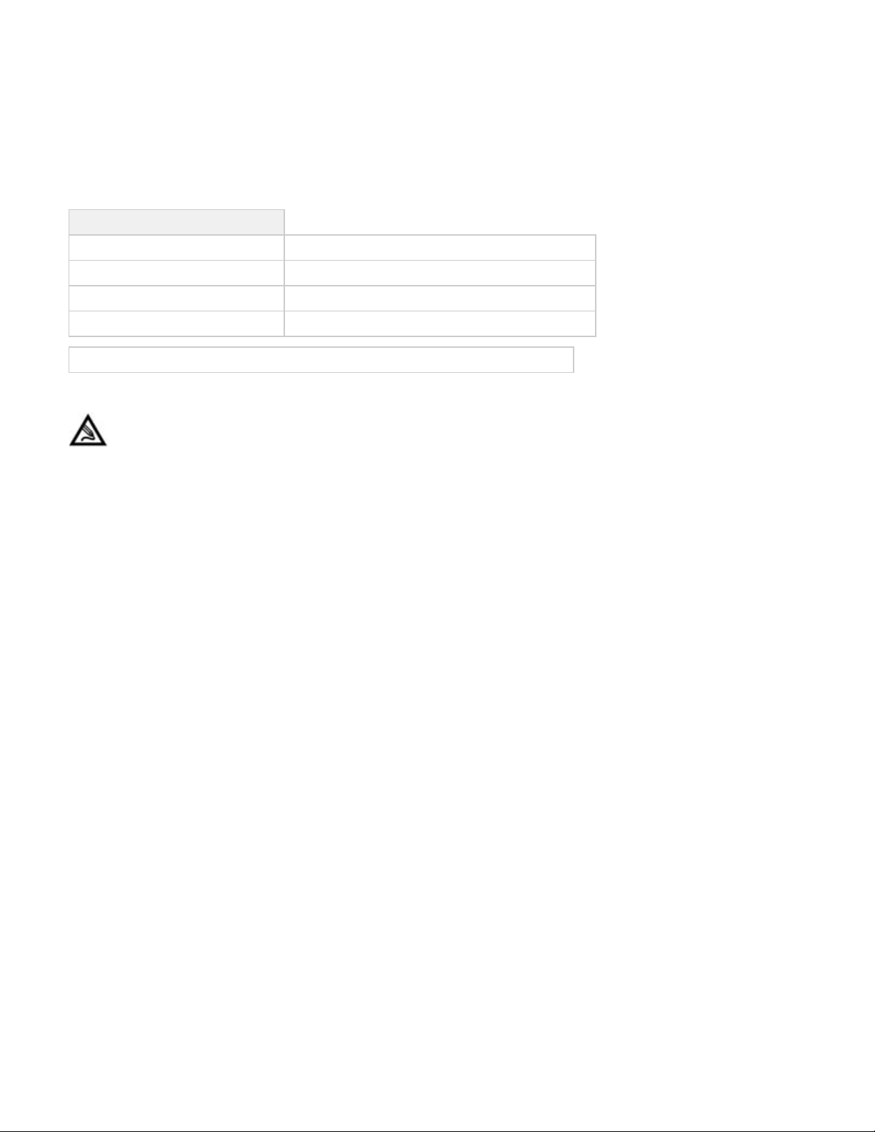
Electrical Specifications
Maximum Power
5 Amp for 100 to 120 VAC~, 2.5 Amp. for 220 to 240 VAC~
Power Consumption
400 W
Input Voltage (auto range)
100 - 240 VAC~, 50/60 Hz
Power Cable (for single phase power)
3-Conductor, wire size according to local electrical code
Recommend use of a back-up power supply and surge protector rated for at least 1000 VA.
Note: The installation of the printer shall comply with the National Standards and Electrical Codes of the country in which it is
placed.
Page 29
Operating Environment & Workspace
CAUTION! Do not install the printer in the same area as equipment that produces heavy electrical power, heavy vibration, or
airborne contaminants that may adversely affect the performance of the printer.
Air Conditioning
The printing process can be temperature-sensitive within certain limits. Room or environmental ambient operating temperature should be
maintained within a range of from 18°C to 28°C (64°F to 82°F); optimally approximately 23°C (73°F). VisiJet® Printing Materials should be
within this temperature range before use.
Storage Requirements for Part Materials
Room Temperature Controls
Heating, ventilation and air conditioning per office building code requirements
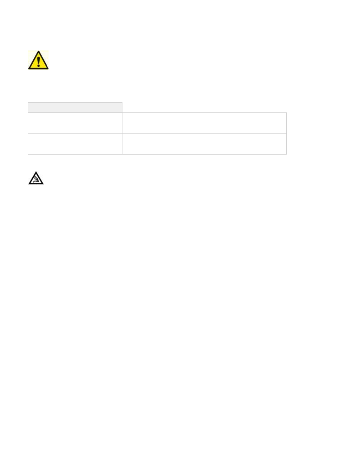
Operating Temperature
18°C to 28°C (64°F to 82°F)
Non-Condensing Relative Humidity
< 30%-50%
Noise
< 60 dBa measure 1 m from the printer
NOTE: When planning the work area and to allow unobstructed access to the side panels when replacing parts, refer to the
dimensions listed.
3D Systems recommends that multiple printers should NOT be located on a single electrical circuit. Each location of the machine requires a
standard wall power outlet, RJ-45 network connection and 122cm (4 ft.) power cord supplied with the accessory kit.
IMPORTANT: Do not damage or discard any packaging materials and cartons. If the printer needs to be returned to the manufacturer, it
should be shipped in its original packaging. If other packaging is used, the customer will be responsible for any shipping damages that
may occur.
Page 30
ProJet™ 1000 & 1500 Printer Dimensions
Printer Dimensions
Page 31
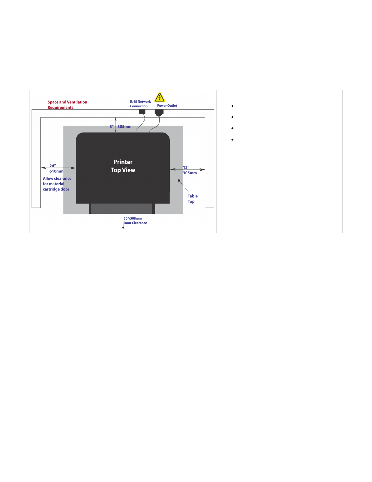
Space Requirements
NOTE: When planning the work area and to allow unobstructed access to the side panels when replacing modules during servicing,
refer to the dimensions in this guide.
NOTE: In addition to the printer's workspace, a plan for a finishing area should be considered such as countertop space for several
printers, a paper wipe dispenser and a trash receptacle.
Preparing the Work Area
Ensure the printer is placed on a stable, level
surface which will not vibrate during operation
To ensure proper air flow, install printer in an
area clear of other objects
To avoid bumping the printer, ensure there is
sufficient room to pass by the work area
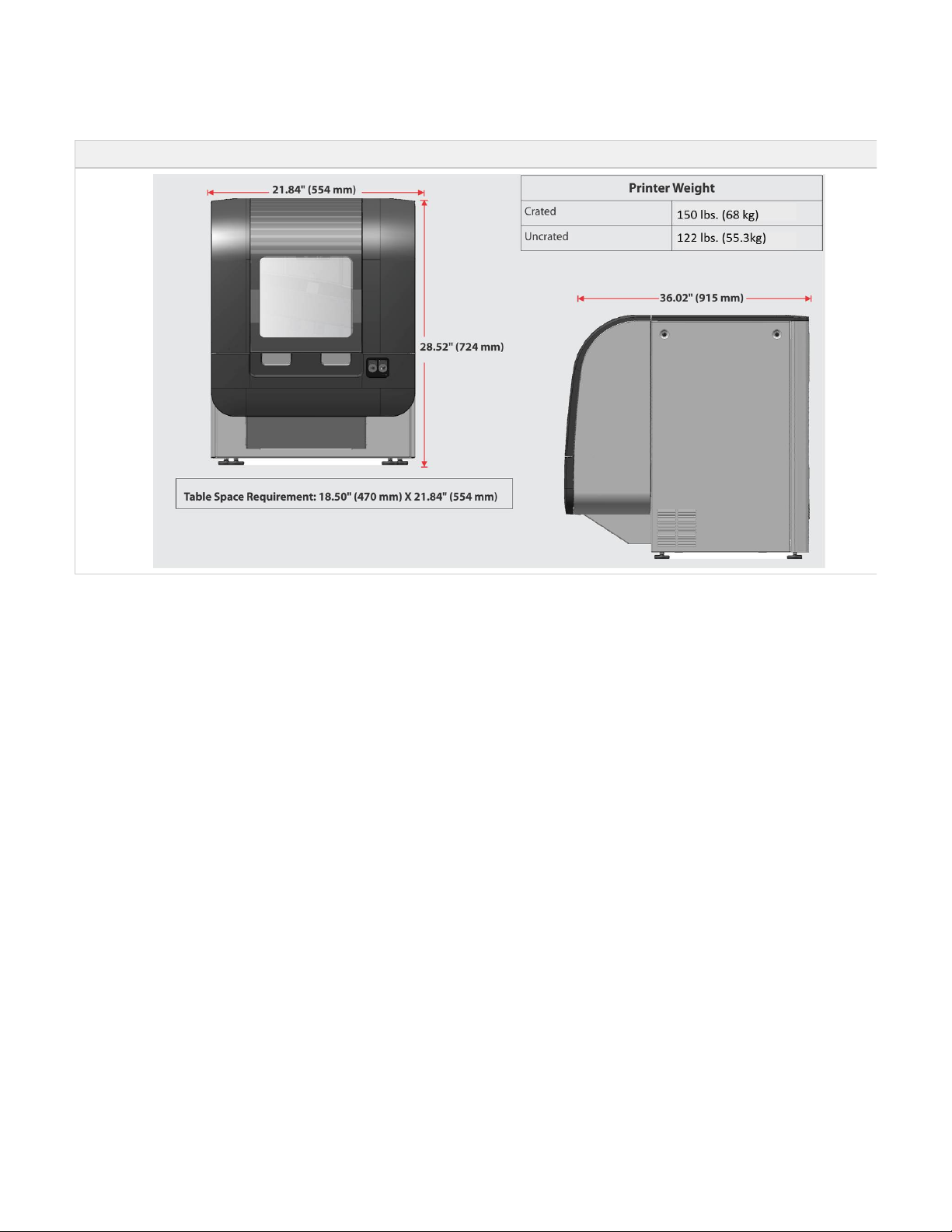
Table Space Requirement: 18.50" (470 mm) X
21.84" (554 mm)
Page 32
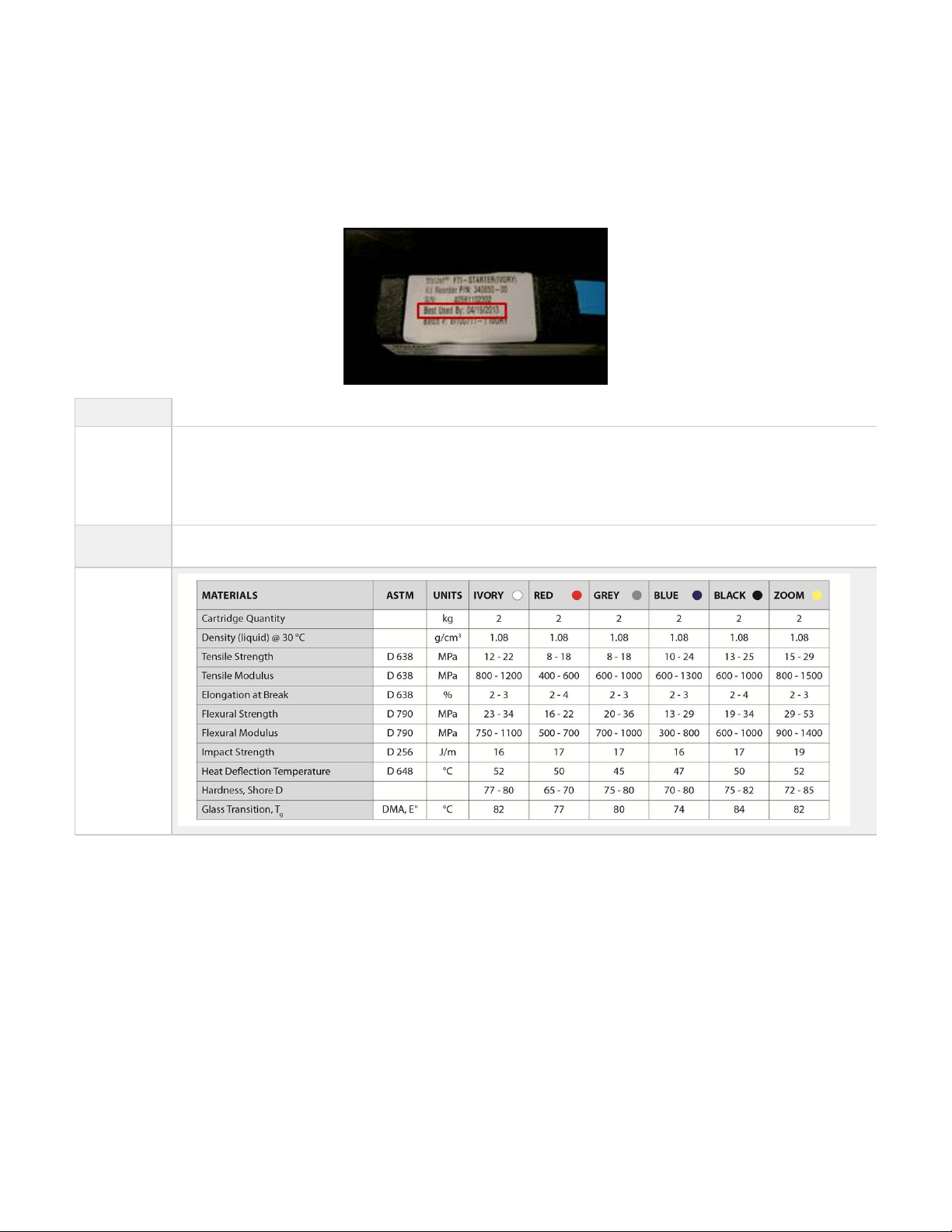
VisiJet® FTI Material Cartridges
The material cartridges should be stored in a conveniently located storage cabinet in proximity to the printer. A cabinet is recommended to protect
against long term exposure to external UV light sources, including sunlight, overhead lighting, or other UV light sources. Material cartridges should
be stored away from strong oxidizing agents, such as hydrogen peroxide.
The shelf life for VisiJet® Materials is 18 months from the "Best Used By" date shown on top of the cartridge.
Material Color
Options
Visijet® FTI-Zoom- The VisiJet FTI-Zoom material also builds up to 40% faster in high speed mode.
Visijet® FTI-Ivory- all purpose material
Visijet® FTI-Grey- great for showing detail in parts
Visijet® FTI-Black- consistent opacity black material
Visijet® FTI-Blue- deep blue material
Visijet® FTI-Red- bright red great for detail and surface quality
Material
Specifications
VisiJet® FTI
Material
Page 33

05. Familiarization
Your printer has a sleek industrial design to complement your office work space. It's easy to use and network ready, featuring an intuitive web
browser interface that provides shared access for your entire group.
System Operation
System Overview
Page 34
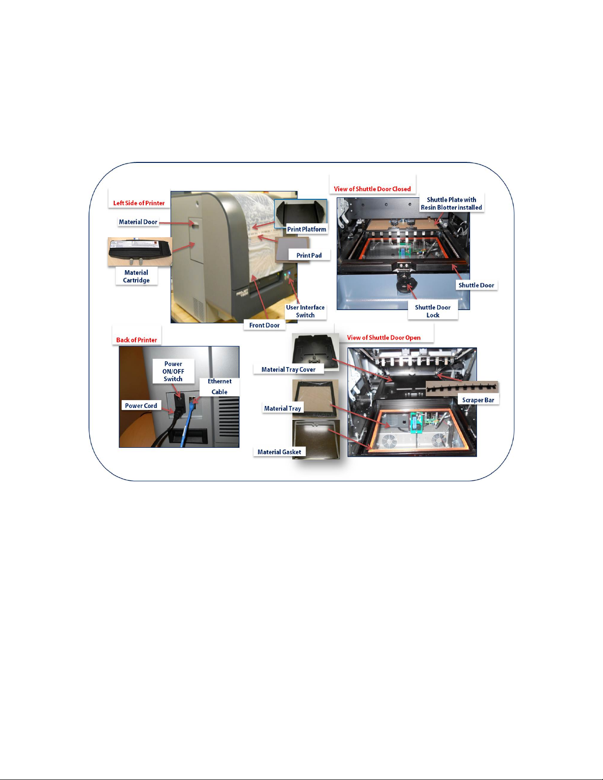
System Operation
ProJet™ 1000 / 1500 Personal 3D Printer
Your printer is easy to set up and operate; you will be making parts in minutes following a few easy steps outlined in the quick start guide. Parts
can be drilled, machined, painted and metal-plated to your meet your needs.
VisiJet® FTI Material
The material produces hard plastic parts with smooth surfaces, exceptional fine-feature detail, durable and balanced physical properties in the
x/y/z directions, and true-to-design part quality. These parts are rugged and tough enough for functional testing and end use parts.
ProJet™ Client Software Operation
Printers can be set up as a network printer or connected to locally using a LAN (Local Area Network). All the necessary software to
prepare and print your design is available on the Projet system. The software uses a web based interface that can be accessed from
any location.
The "Home " screen is the job control center that allows any user to view the print as it is printing, and pause or abort prints and
monitors the status of the current print.
The software has the capability to add users at different levels of access and control.
Equipped with a diagnostic program for troubleshooting and pre-print checks
The software will check for updates and informs you when it is available to install.
E-mail notification of print start, completion and print pause status
Preview support structures before printing to aid in optimal part orientation. Supports can be added to the existing support structure.
Part file verification and repair tool
Easy menu driven user interface
Access to powerful online user guide and other application support tools
On-board system diagnostics tools
Remote service support function for push-button remote service session initiation
Print Preview allows the user to place parts on the print platform to scale the size, align planes in various directions, generate and
preview supports, mirror, translate and rotate the part on the platform before printing.
The "Help" button located in the corner of the screens will give detail information of the screen's functionality.
When Print preview opens, it will see the tip of the day. These tips will give suggestions on how to manipulate your print in print preview
for the beat placement in the printing area.
Page 35
System Overview
ProJet™ Personal 3D Printers can build 3-D parts within hours using standard STL files.
ProJet™ parts can be used for testing and verification the same day. The printer may be used for all phases of design; from concept build to
functional testing and assembly verification.
Install, operate and maintain the ProJet™ Personal 3D Printers using the 3dpedia program that allows the user to browse through the user's
guide and ProJet Client Software to utilize the diagnostic monitoring system.
Page 36

06. Printer Installation
NOTE: Do not damage or discard any packaging materials or carton. If modeler needs to be returned to the manufacturer, it should
be shipped in its original package. If other packaging is used, the customer will be responsible for any shipping damages
that may occur.
06.1 What is Included with the Printer
06.2 Uncrating Printer
06.3 Leveling Printer
06.4 Printer Preparation
06.4.1 Cleaning Image Mirrors
06.4.2 Print Pad and Print Platform Installation
06.4.2A Removing Print Pad from Platform
06.4.3 Material Tray Cover Installation
06.4.4 Material Tray Gasket Installation
06.4.5 Material Tray Installation Instructions
06.4.6 Coater, Scraper Bar Installation
06.4.7 Material Cartridge Installation
06.4.8 Resin Blotter Installation
06.4.9 Printer Preparation for Material Color Change
06.5 Network and System Setup
06.5.1. Basic Printer Network Information
06.5.2 Network Setup for Online Printer Registration
06.5.3 Network Setup for Offline Printer Registration
06.5.4 Printer Network Configuration & User Profile
06.5.5 User ID and Password
06.5.6 Print Preview Installation
06.5.7 Update Software
Page 37
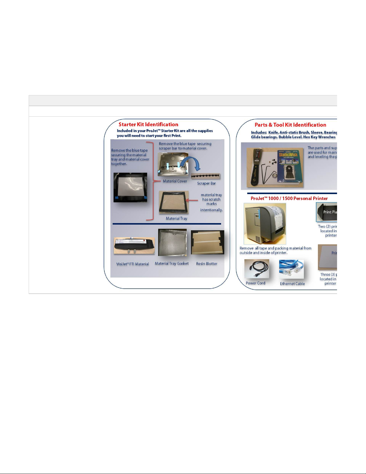
06.1 What is Included with the Printer
IMPORTANT: Do not damage or discard any packaging materials and cartons. If printer needs to be returned to the manufacturer, it
should be shipped in its original packaging. If other packaging is used, the customer will be responsible for any shipping damages that
may occur.
Ensure that all parts and supplies are included in the kits and in the printer packaging. If you find that your packages are incomplete, please
contact your local 3D Systems reseller.
Printer Packaging Includes:
ProJet 1000 & 1500 Printer
Page 38
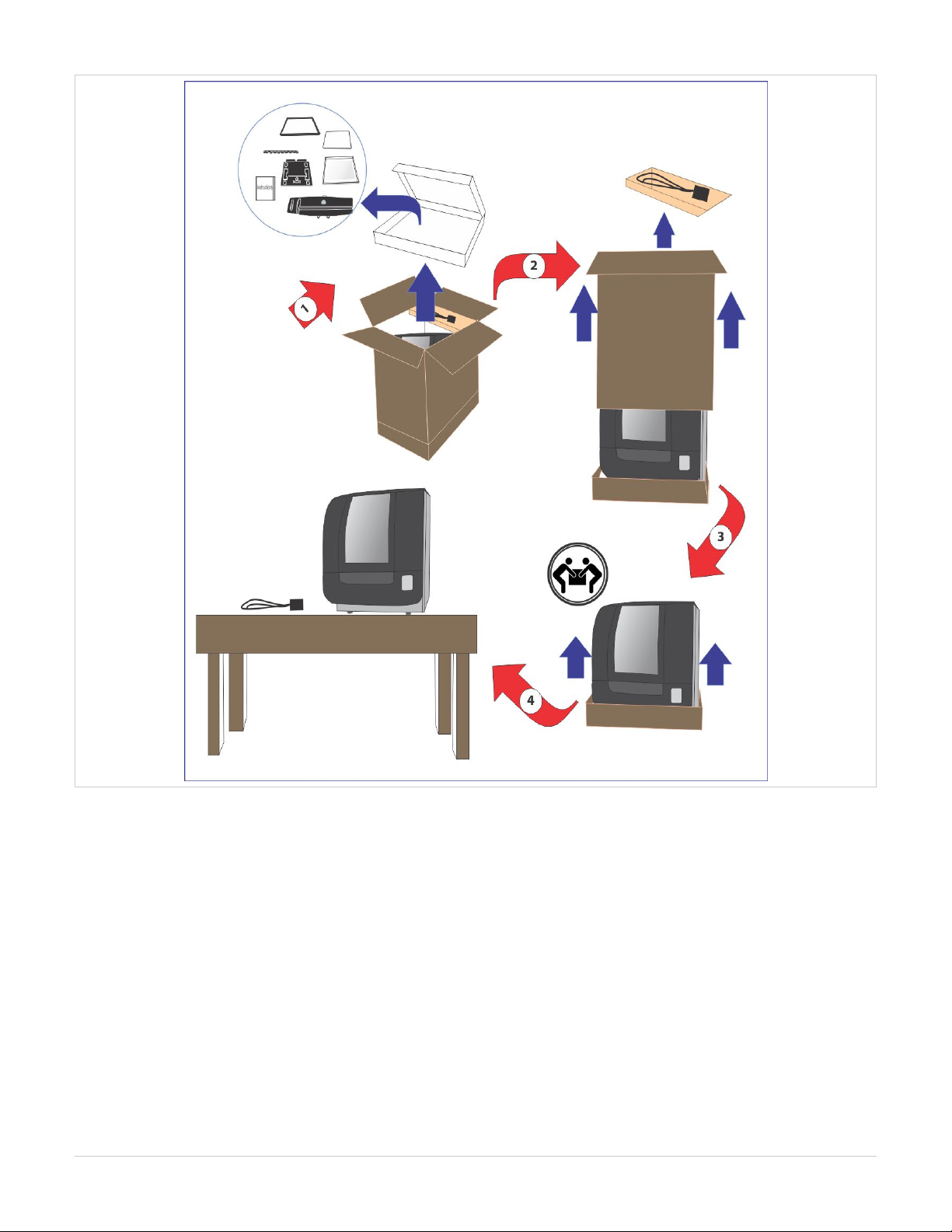
06.2 Uncrating Printer
Ensure that printer is placed on a sturdy work table and meets the requirements that are described in . Please follow theseSystem Requirements
requirement to ensure optimal operation of your printer.
Cut tie straps and open the top of package.
Remove the ProJet Material Starter Kit, Parts & Tool Kit, power cord, internet cable, print pads and build platforms.
Lift carton up over printer.
Remove the corner boards from the bottom of carton.
Lift printer from carton bottom.
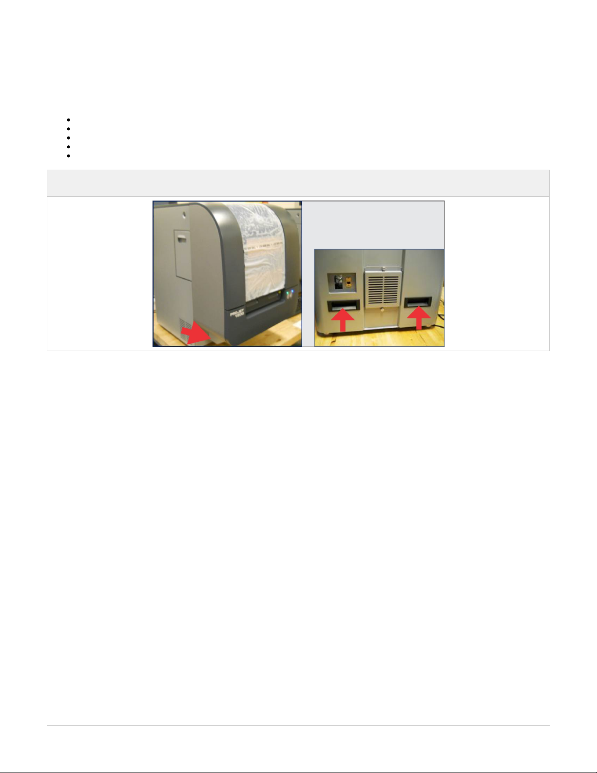
NOTE: With two people lifting printer, lift with the handles located at the back of printer; lift at each front end where arrows are
pointing.
Page 39
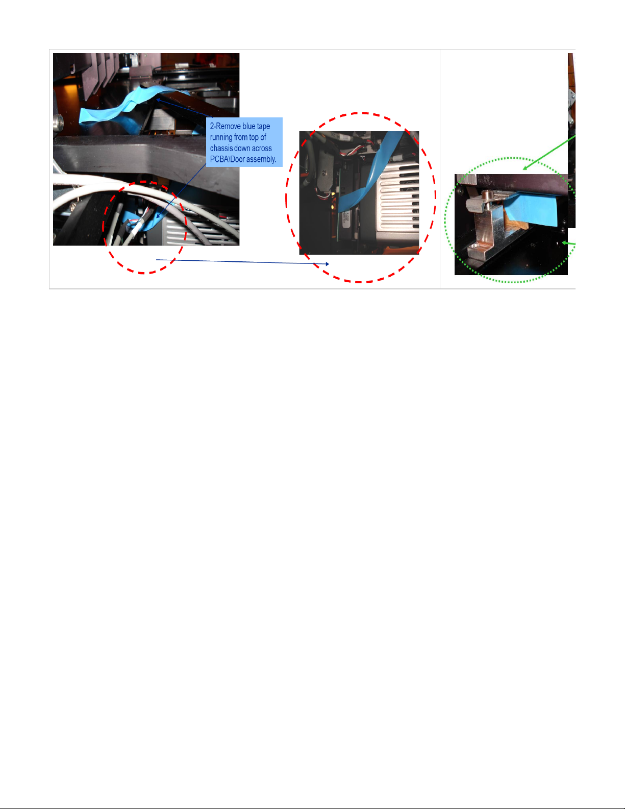
Remove all packing materials from the inside and outside of printer.
Page 40
Page 41
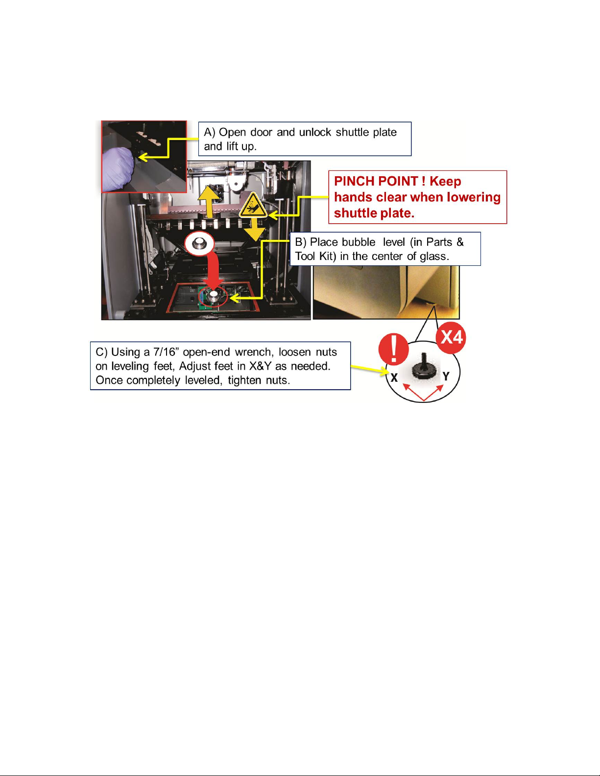
06.3 Leveling Printer
It is very important that the printer is completely leveled to ensure good part quality. Ensure the work table is sturdy and does not allow
movement during printer operation.
Page 42

06.4 Printer Preparation
NOTE: Before starting the printing process, Steps 06.4.1 - 06.4.7 must be installed for proper printing operation.
06.4.1 Cleaning Image Mirrors
06.4.2 Print Pad and Print Platform Installation
06.4.3 Material Tray Cover Installation
06.4.4 Material Tray Gasket Installation
06.4.5 Material Tray Installation Instructions
06.4.6 Coater, Scraper Bar Installation
06.4.7 Material Cartridge Installation
06.4.8 Resin Blotter Installation
06.4.9 Printer Preparation for Material Color Change
Page 43
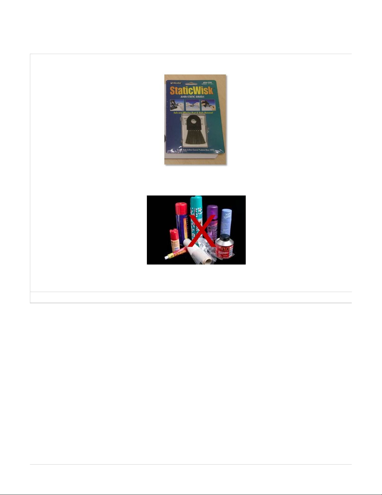
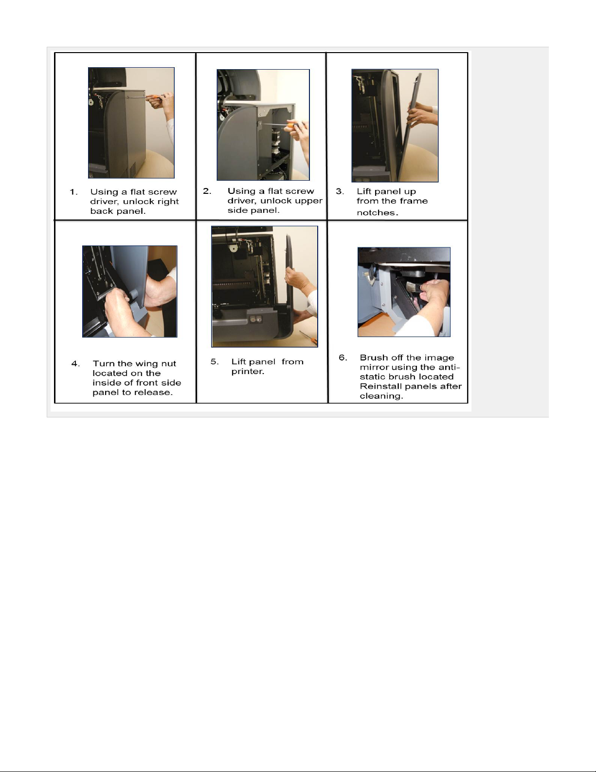
06.4.1 Cleaning Image Mirrors
It is very important to clean the image mirror after unpacking the printer and before printing to remove any dust that may have occurred during
transit. This is accomplished using the anti-static brush that is packed in your printer's tool kit.
Never use solvents or cleaning materials other than the anti-static brush. Doing so could cause scratches on the mirrors that affects the quality of
the print.!
Please follow the instructions below to properly clean mirror.
Page 44
Page 45
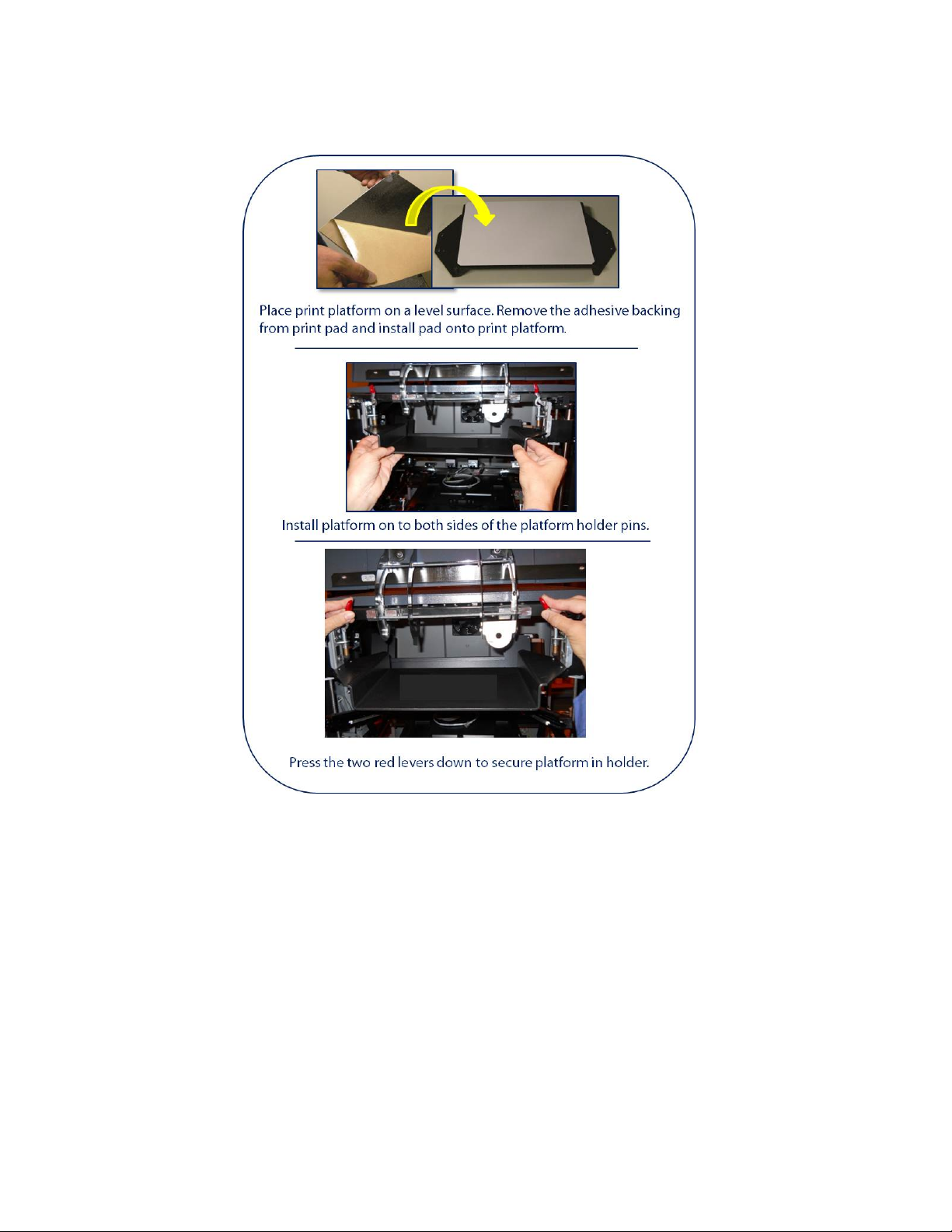
06.4.2 Print Pad and Print Platform Installation
06.4.2A Removing Print Pad from Platform
Page 46
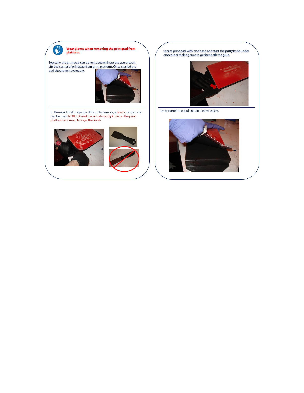
06.4.2A Removing Print Pad from Platform
Page 47
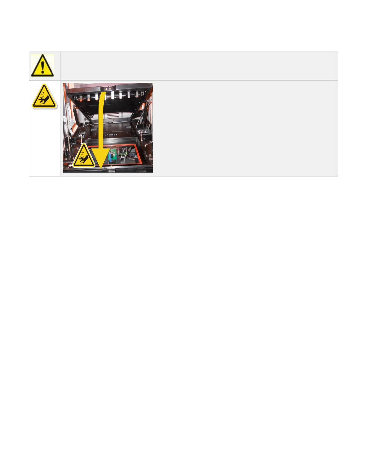
06.4.3 Material Tray Cover Installation
Caution: A pinch point exist between the shuttle plate and the frame. When closing the shuttle plate, keep fingers and
hands clear from the pinch point area.
Page 48
Page 49
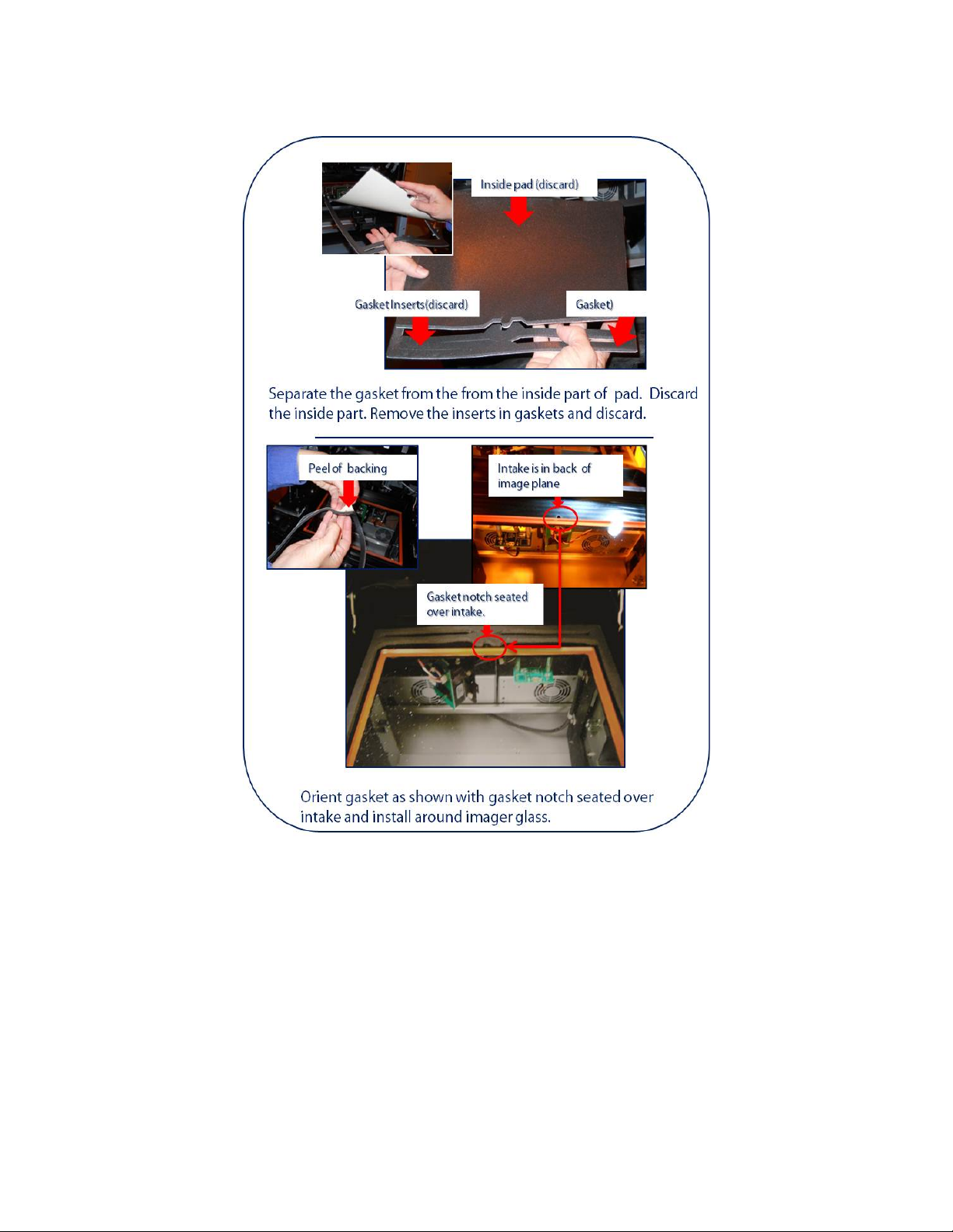
06.4.4 Material Tray Gasket Installation
Page 50
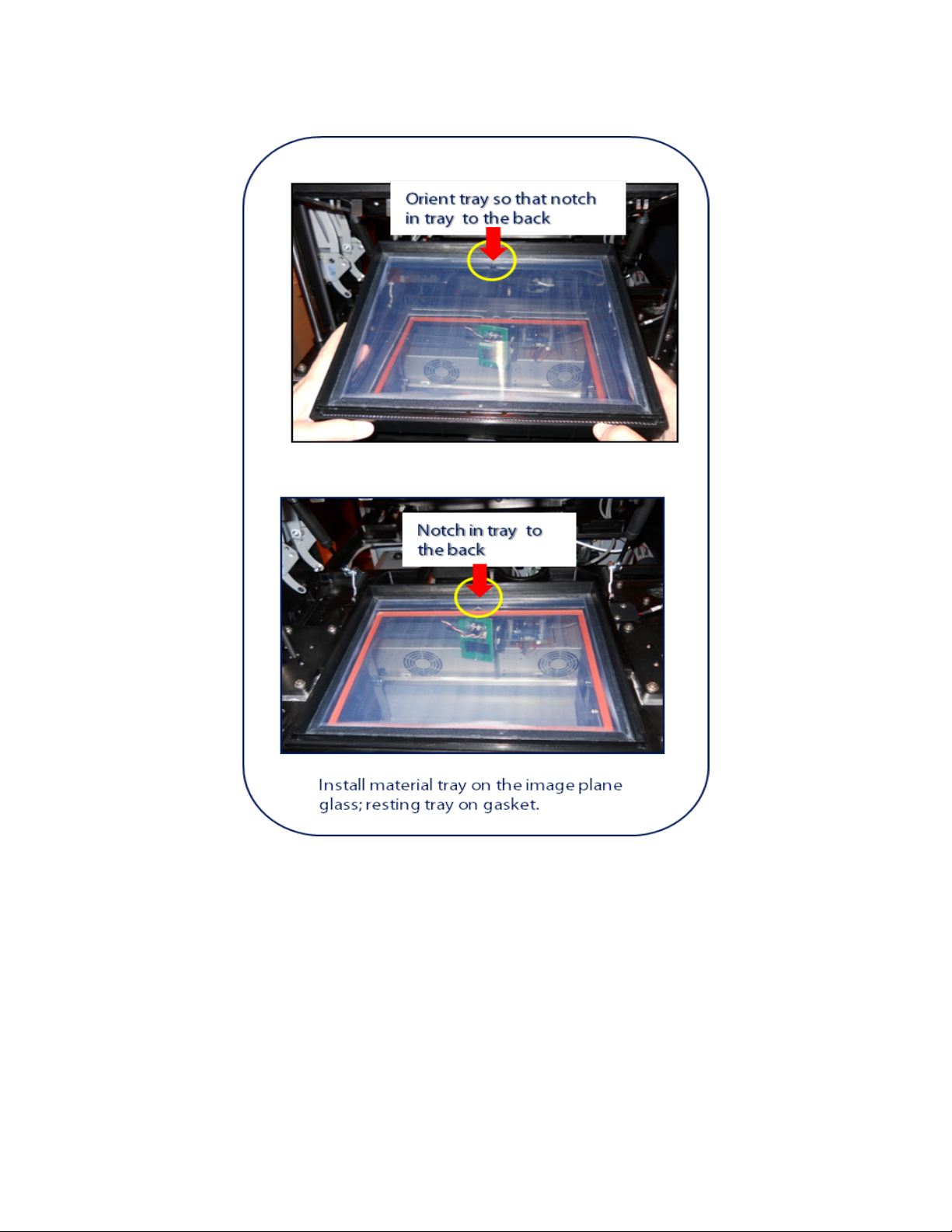
06.4.5 Material Tray Installation Instructions
Page 51
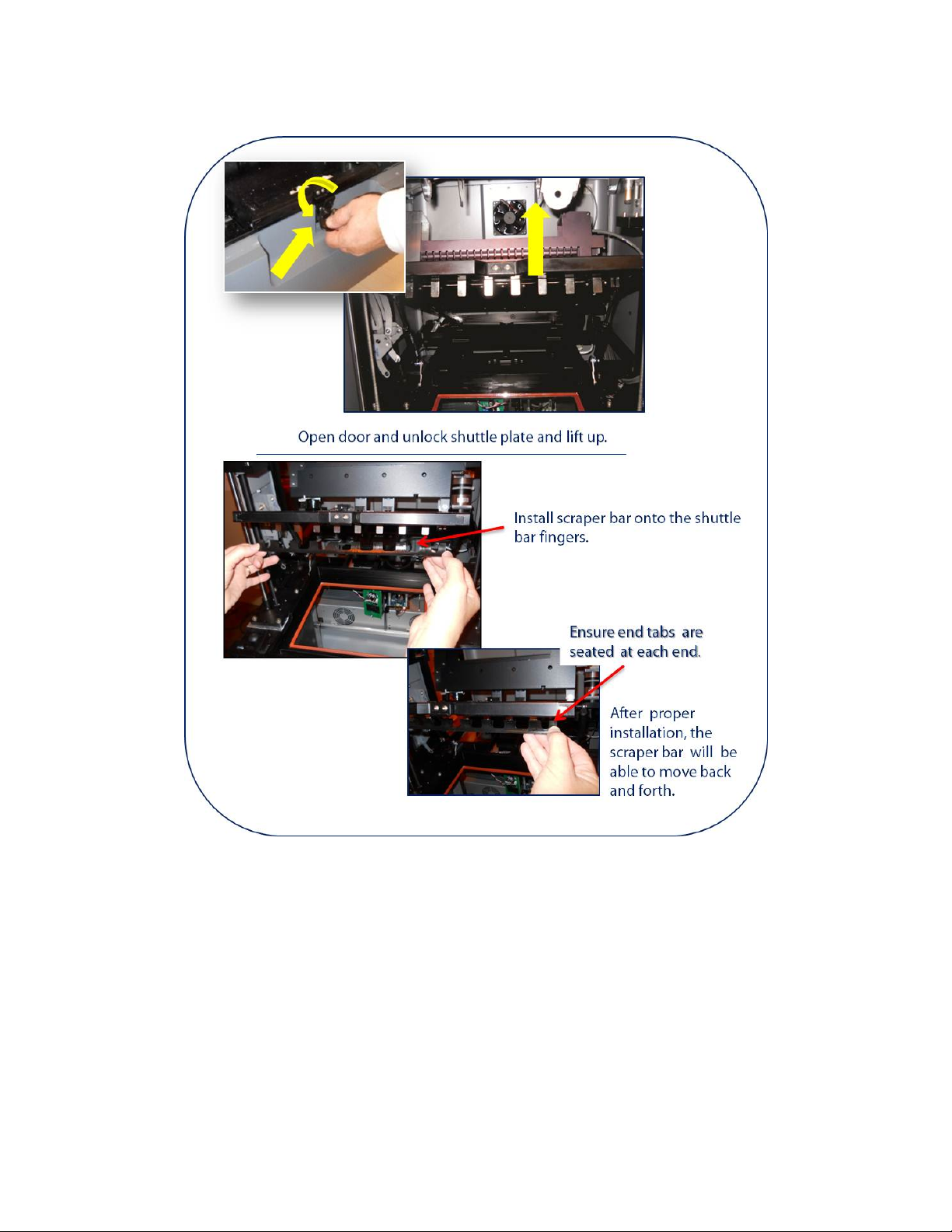
06.4.6 Coater, Scraper Bar Installation
Page 52
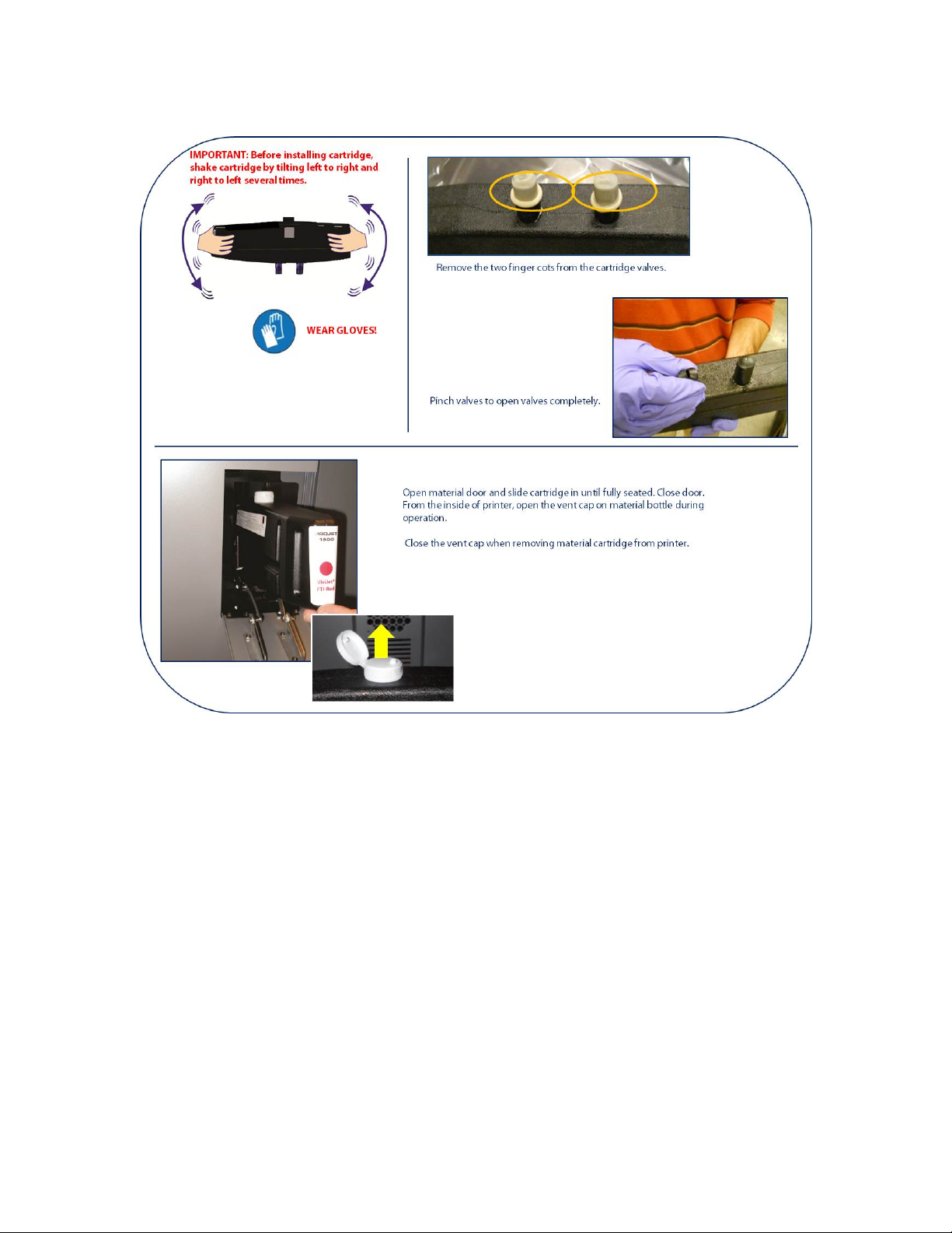
06.4.7 Material Cartridge Installation
Page 53
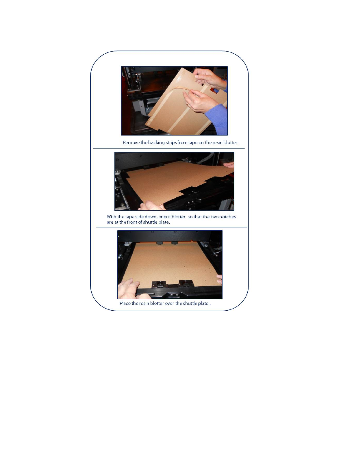
06.4.8 Resin Blotter Installation
Page 54
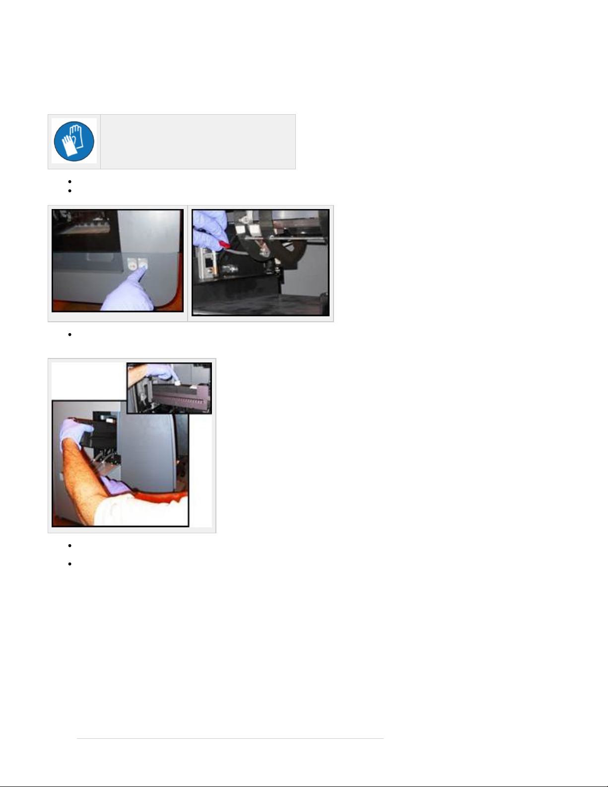
06.4.9 Printer Preparation for Material Color Change
After a print is completed and another material color is needed for printing, the tray will need to be changed. This also includes changing the
scraper bar, material gasket, material.
Wear gloves when handling VisiJet® FTI Material.
Pause printer by pressing the pause button on printer or using the "pause printer button" in the software.
Remove print platform from the platform holder by lifting the red levers up on each side of platform.
Close material cap and remove material cartridge. Note: Cartridge must be removed before shuttle plate can be unlocked and
lifted.
Using Isopropyl alcohol and a lint free cloth, thoroughly clean shuttle plate. Ensure to clean the material from the two valves located in the
front of shuttle plate.
Unlock shuttle plate and lift up.
Page 55
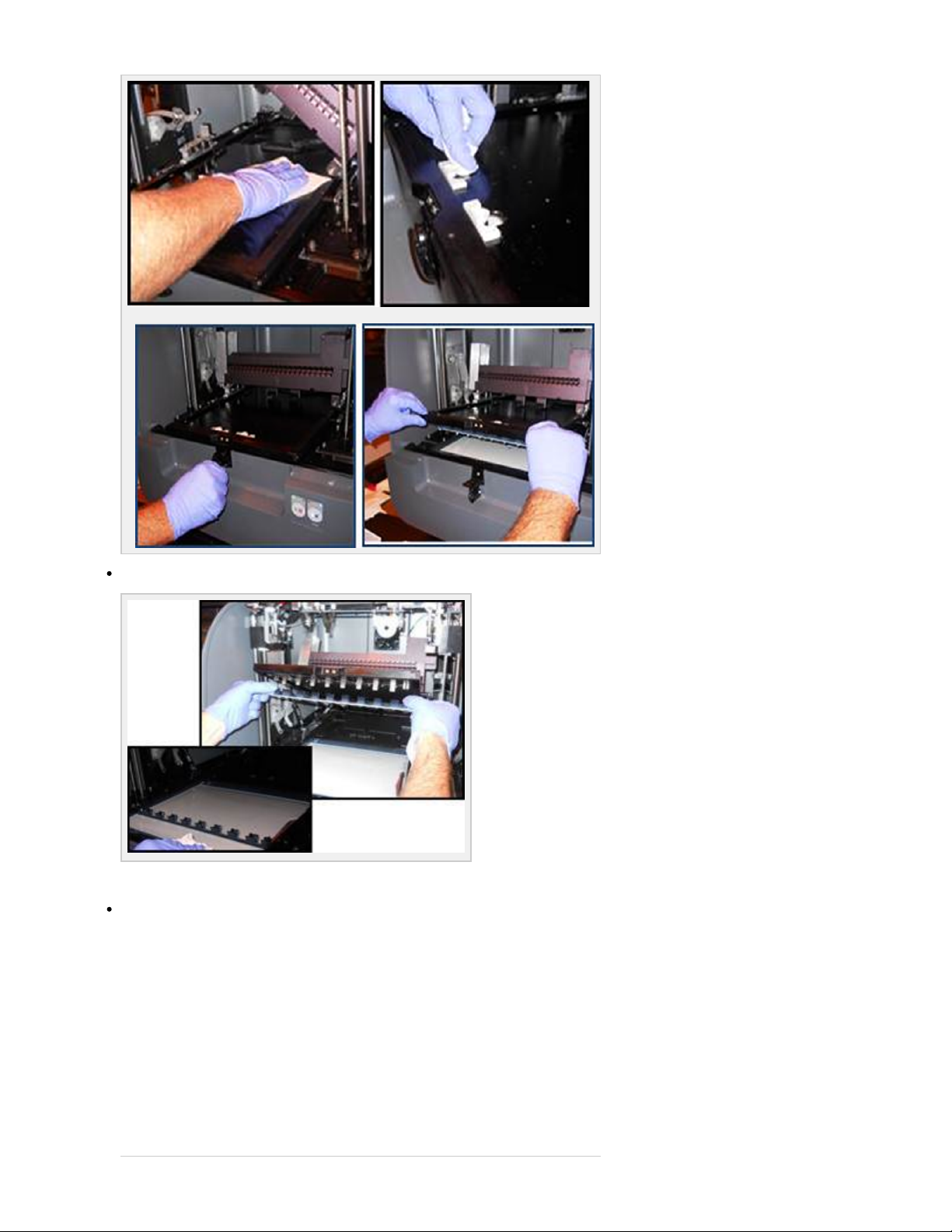
Remove scraper bar by pulling down on each end to release it from the shuttle fingers. Place scraper bar in material tray.
*To start a new print with another material cartridge, refer to Printer Set Up Module.
Using Isopropyl alcohol and a lint free cloth, thoroughly clean shuttle plate fingers and the front of shuttle plate.
Page 56
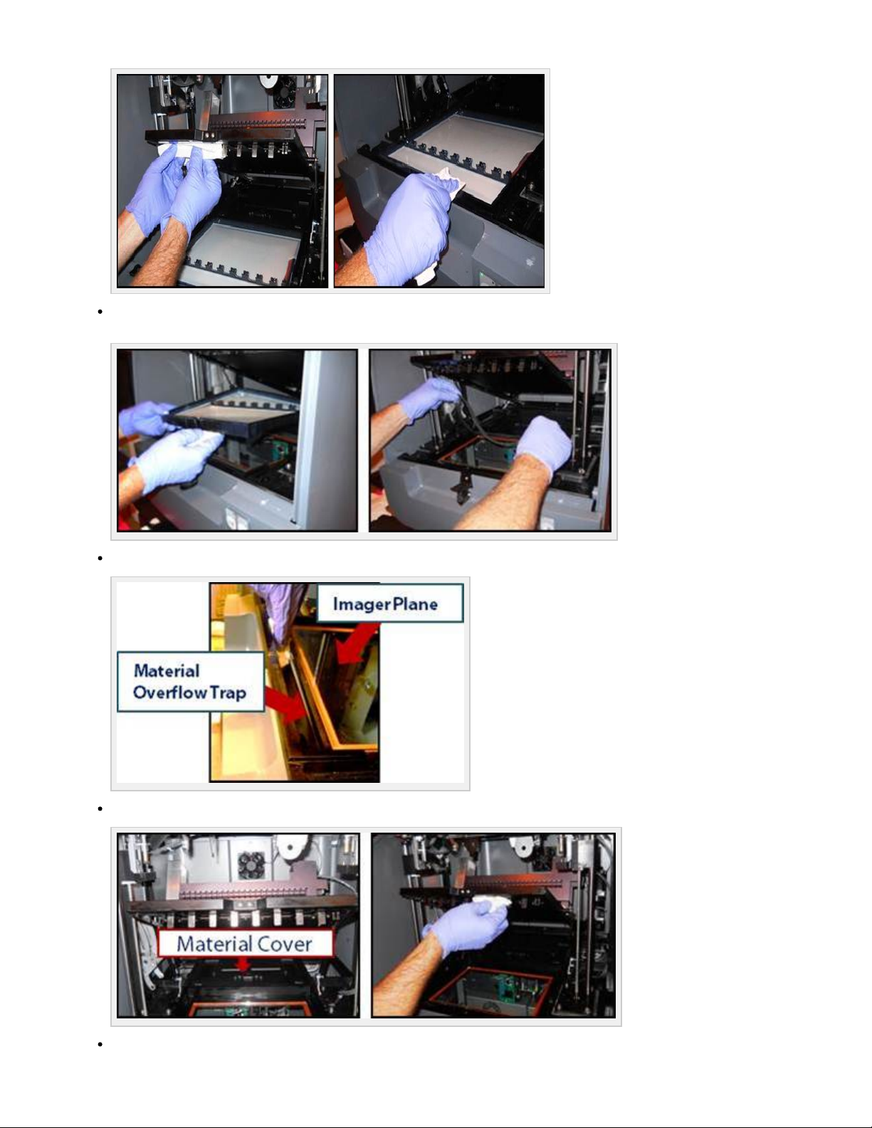
Lift out material tray and wipe the front of tray with Isopropyl alcohol and a lint free cloth. Remove material gasket and dispose gasket.
Set material tray and scraper bar aside.
Clean the image plane glass and the material overflow trap located at the front of image plane.
Remove material cover and place it over the top of material tray for curing process of waste material.
To start a new print with another material cartridge, refer to:
Page 57

06.4.1 Cleaning Image Mirrors
06.4.2 Print Pad and Print Platform Installation
06.4.3 Material Tray Cover Installation
06.4.4 Material Tray Gasket Installation
06.4.5 Material Tray Installation Instructions
06.4.6 Coater, Scraper Bar Installation
06.4.7 Material Cartridge Installation
Page 58

06.5 Network and System Setup
The topics in this section describe how to install the printer onto the network. Before the printer can be used, the following tasks must be
performed:
06.5.1. Basic Printer Network Information
06.5.2 Network Setup for Online Printer Registration
06.5.3 Network Setup for Offline Printer Registration
06.5.4 Printer Network Configuration & User Profile
06.5.5 User ID and Password
06.5.6 Print Preview Installation
06.5.7 Update Software
Page 59

06.5.1. Basic Printer Network Information
Printer uses an internal computer running Windows XP on a Celeron® processor.
Printer must be connected to a network through a built-in Ethernet adapter located on the back panel or directly to a PC using cross over
cable connection.
Before installation, ensure that the network and PC meets to ensure optimum operation."System Requirements"
Page 60
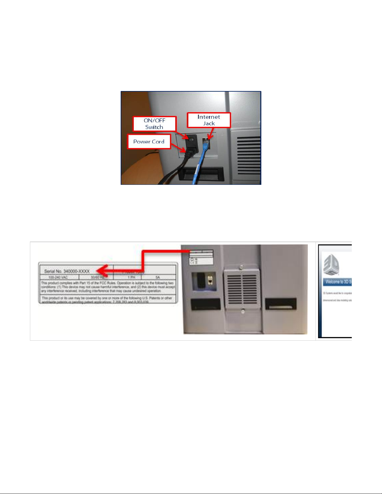
06.5.2 Network Setup for Online Printer Registration
It is important to have the components installed described in before network installation. During printer's initialization, it willPrinter Preparation
detect if the material cartridge, material cover and other parts described in Printer Preparation are installed. This will prevent errors occurring
during initialization.
Plug the power cord into printer's power supply and to the facility outlet.
Plug the internet cable into the printer's internet cable jack and into your PC.
Toggle the switch to "ON."
NOTE: Once powered on, the printer will initialize for approximately 3 minutes.
The printer does not have a monitor so therefore all interaction is done through the client's workstation.
Once workstation is connected to the printer, enter the printer's serial number (on the back of printer) into Google Chrome, Foxfire web browser
as specified in . Enter the printer's serial number into the browser; ( . Once connected toClient's Computer & Network Interface http://340000-XXXX
your printer, the welcome screen will appears. Follow the step by step software instructions to register your printer.
Follow to configure your printer.Printer Network Configuration & User Profile
Page 61
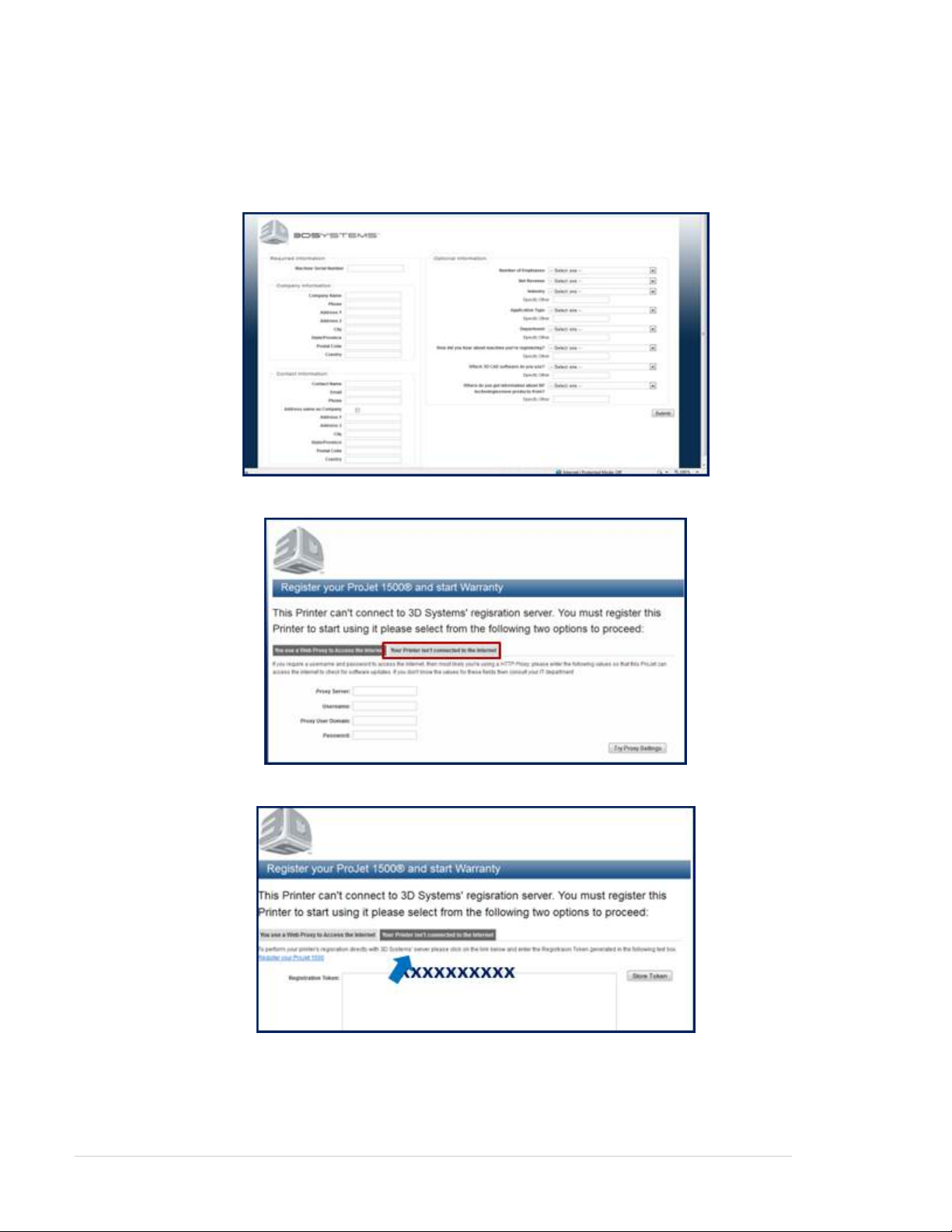
06.5.3 Network Setup for Offline Printer Registration
If internet service is not available where the printer is located, you will need to get access from another location to obtain the registration token.
This token allows you to continue registering the printer. A RJ45 cross-over cable will be needed to communicate with the printer from your PC.
In the web browser that is specicied in , please enter . Fill in the requiredClient's Computer & Network Interface http://registration.3dsystems.com
information and click on submit.
To obtain the registration token, select "Your Printer isn't connected to the internet" tab.
Copy the registration token. You will need this token to continue registering once you get to the printer's site.
Turn power on to the printer and connect the cross-over cable to your PC and the back of ProJet 1000 / 1500 Printer.
Page 62
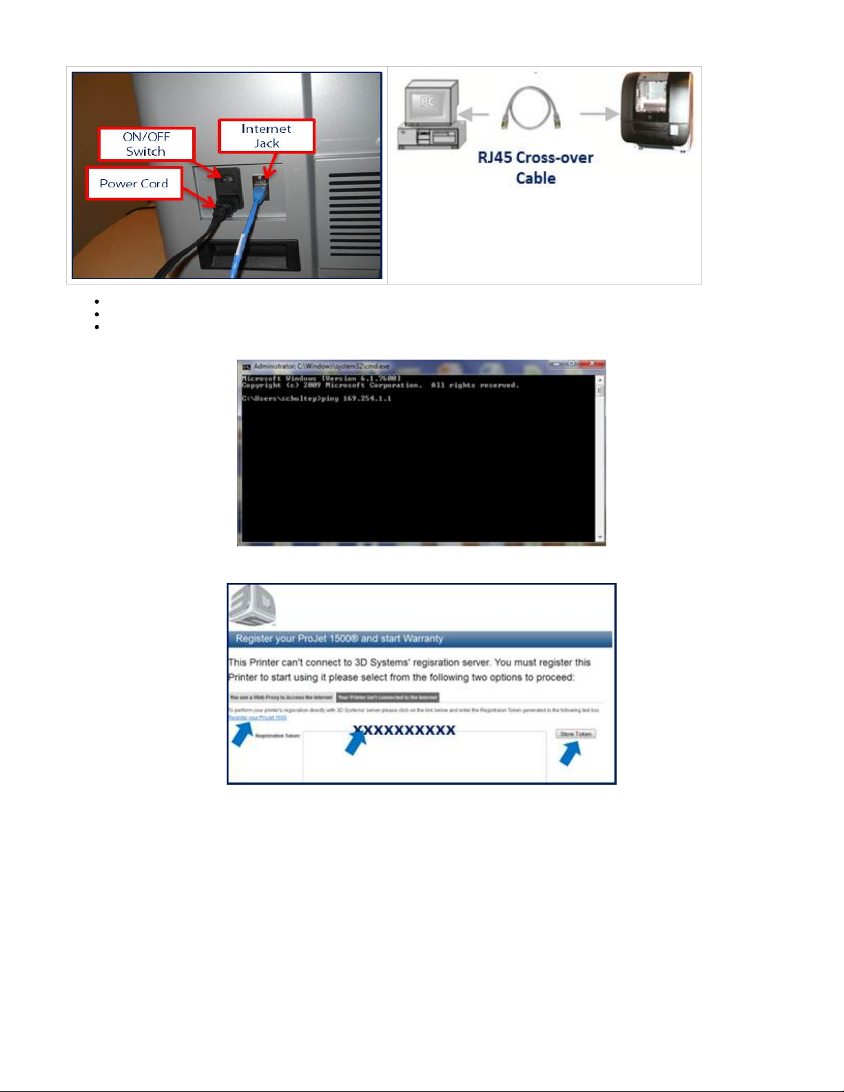
Click on the Start button and choose "Run." Type the letters "cmd" and press "OK."
Type the words "ipconfig/all" at the command prompt window once it opens. A long series of numbers will appear.
Scan through the list of numbers that appears. Next to the words "IP Address" will be the IP address 169.254.1.1 that the DHCP has
assigned.
Cut and paste the registration token and select "Store Token." Continue registering the printer by selecting "Register your ProJet 1000 / 1500."
Follow to configure your printer.Printer Network Configuration & User Profile
Page 63
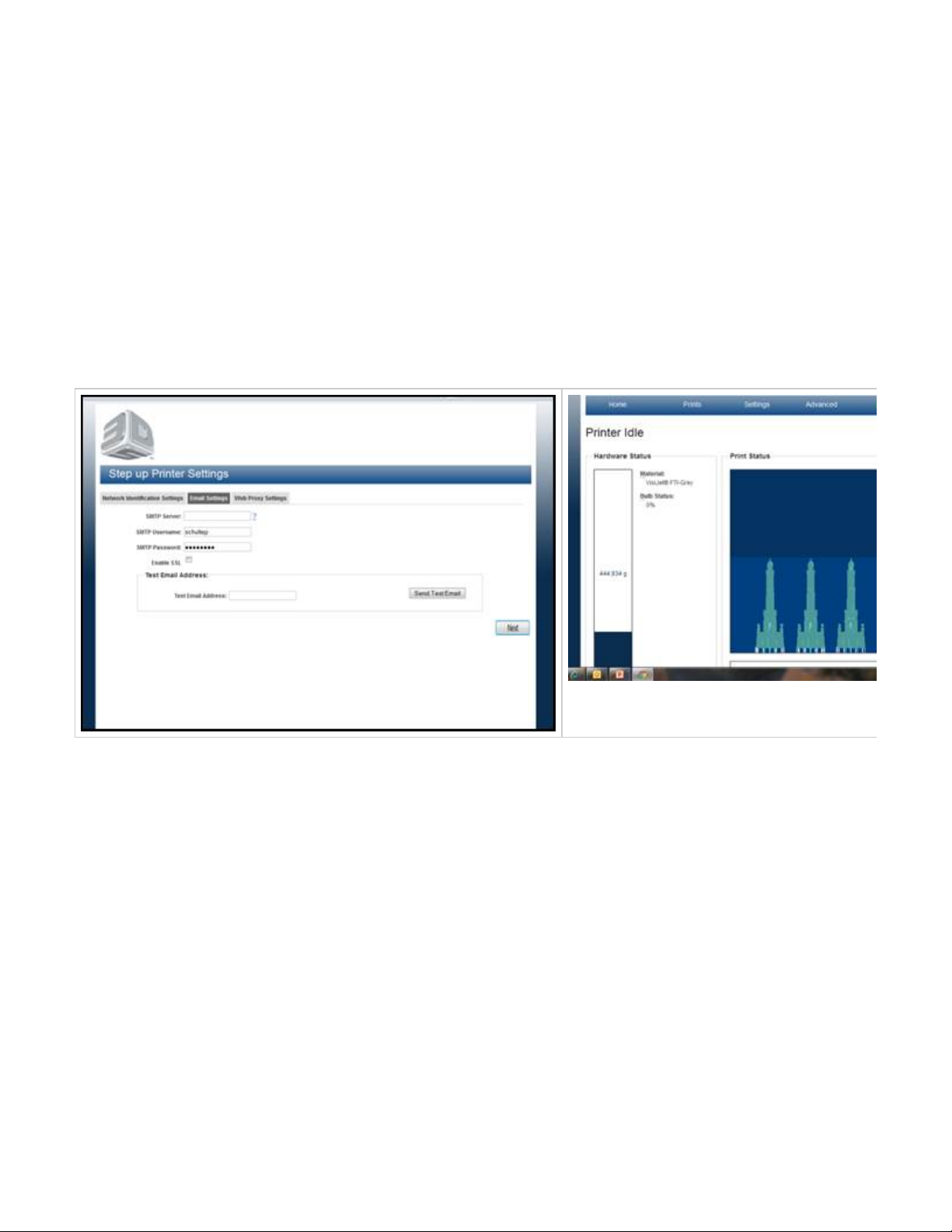
06.5.4 Printer Network Configuration & User Profile
Printer Network
DHCP is the default setting for the printer. When the computer is turned on, it will look for the DHCP server in the network and will automatically
set up your IP address (recommended setting).
If Static IP address is desired, the system's administrator should configure the fields in the highlighted area to access the printer. Be sure to
document the IP address. NOTE: Use extreme caution when changing the static IP address. *
IMPORTANT: If the IP address is not correct, you will not be able to view the modeler in the network.
To change Machine Name to your own user-friendly name, enter the new name in the Machine Name box.
Enter an e-mail address that will that will receive the job status uploads, notifications and system updates from the printer's server.
NOTE: If you choose a new name for the printer instead of the host name, be sure to write the new name down and keep it in a secure
location. The printer's name is used to log in to your printer.
Click "Next" to continue with configuring your printer network. After the network configuration completed, the printer desktop will appear.
Page 64

06.5.5 User ID and Password
The administrator can login using the username and password they have selected. You can assign a User ID and password to each client to
enable them to access the printer. Once the User ID and password are set, the user may change the password to one that can be easily
remembered.
Type in your User-id and password in the Login window that was assigned.
Click Submit to continue.
The printer is now setup.
NOTE: 3D Systems recommends you select a administrator who can be available to oversee the proper operation of the printer.
Page 65
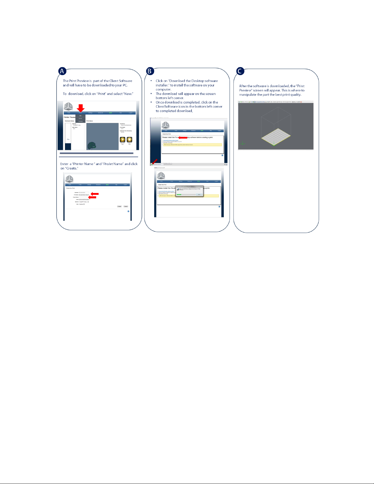
06.5.6 Print Preview Installation
Please install the ProJet Desktop software before creating a print.
|
Page 66
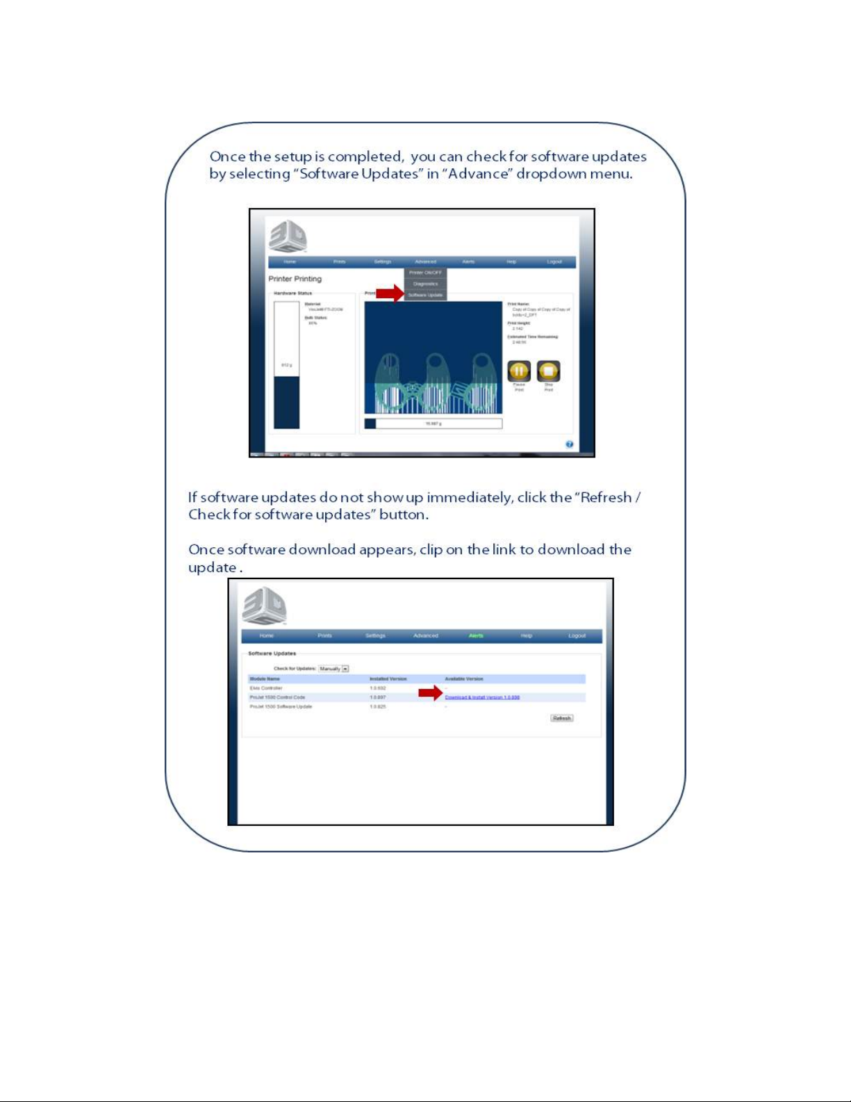
06.5.7 Update Software
Page 67

07. ProJet™ Client Software Overview
Click on the screens to see the various functions of the screens including a description of their functionality.
Alerts
Create New Print
Diagnostics
Current Status
Elevator Motion
Routines
Sensors and Output
Shuttle Motion
UV Shutter Motion
Email Settings
Help
Home Page
Network Identification Settings
Printer ON-OFF
Printer User Account
Prints Queue
Print Tracking (TSV Report)
Software Updates
Page 68
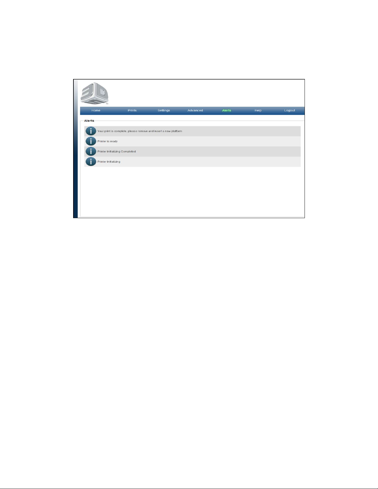
Alerts
On the "Home" page, click on "Alerts" to view current status of your machine.
The purpose of the Alerts is to inform you of what state the system is in.
Page 69
Create New Print
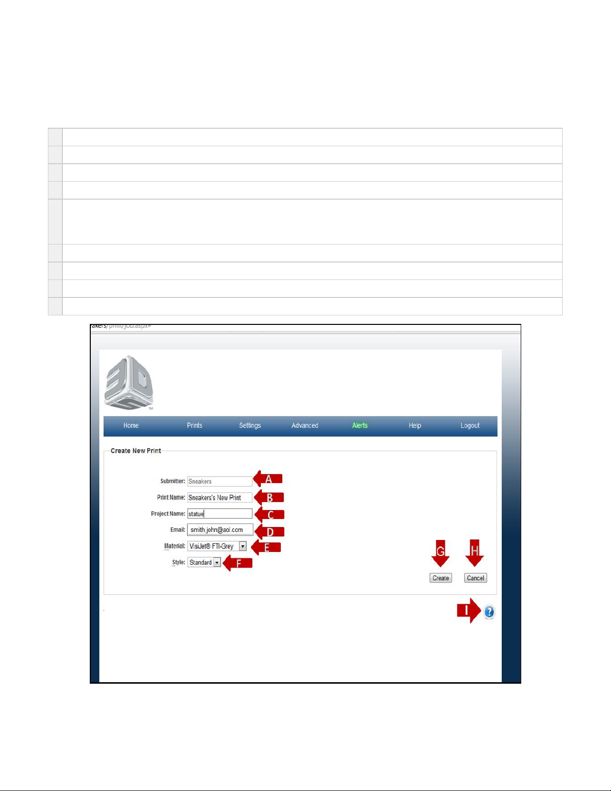
On the "Home" page, click on "Prints" and select "New" in the drop down menu to view "Create New Print" screen.
The purpose of the New Print Create Page is to allow users a method for naming prints, projects, and choosing the materials and print styles
before printing.
A
Submitter is defaulted to the printer hostname.
B
Print Name is entered by the User. Note the print name cannot be a duplicate of an already submitted build.
C
Print Name: Project Name is entered by the User.
D
Email defaults to the User logged into the printer and emails are sent with print start, pause, and print completed information.
E
The material cartridge currently in the printer is shown in black. All other materials are shown in grey print. A print job may be created from
any material in the Material List, but only the print job that matches the material currently in the printer may be printed at any time. If a print
job created in a material NOT currently in the printer, simply replace the material cartridge, material tray, gasket, and coater bar for the
desired print
F
Some materials have more than one mode of print available. Standard Style is the default print mode.
G
Click on Create to send the print job to Print Preview before submitting it to the print queue.
G
Click on Cancel to cancel the new print.
I Click on the to obtain help for this particular screen.?
Page 70

Diagnostics
There are six diagnostic pages that allows you to view motion of the Shuttle, UV Shutter and Elevator. The purpose of the Sensors & Outputs
page is to provide feedback from various sensors and provides the ability to toggle some of the system hardware on and off. The Routine page
performs maintenance routines for material tray, curing waste material and performing a material coat test.
Current Status
Elevator Motion
Routines
Sensors and Output
Shuttle Motion
UV Shutter Motion
Page 71
Current Status
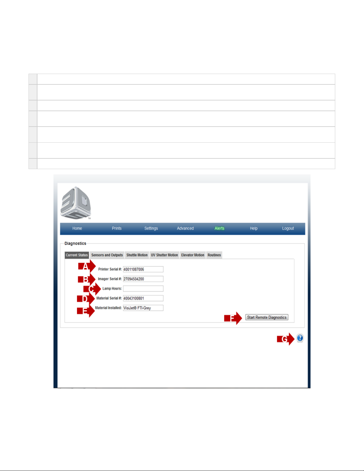
On the "Home" page, click on "Advanced" and select "Diagnostic" in the drop down menu to view "Current Status Screen" screen.
The purpose of the Current Status page is provide a forum where the system can provide the status on the major components of the system.
A
Printer Serial Number - each system has its own unique system serial number. This number will be required when requesting service.
B
Imager Serial Number - the installed imager has its own unique imager serial number. This number will be required when requesting
service on a system's installed imager.
C
Lamp Hours - The number of hours in which the installed imager has been turned on.
D
Material Serial Number - each material cartridge has its own unique material cartridge serial number. If a cartridge is installed in the system,
the serial number will be reported in this location.
E
Material Installed - this is the type of material that is currently installed in the printer. If a material cartridge is installed in the system, the
material type will be reported in this location.
F
The Start Remote Diagnostics button is a user initiated permission button that allows one of 3D Systems' Service Technicians the ability to
remote access the printer. This allows for the service technician to access information to restore the printer to proper working condition..
G Click on the to obtain help for this particular screen.?
Page 72
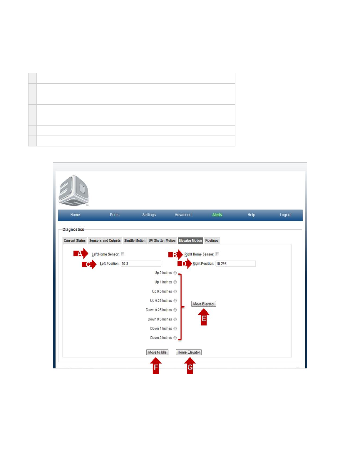
Elevator Motion
On the "Home" page, click on "Advanced" and select "Diagnostic" in the drop down menu to view "Elevator Motion" screen.
The purpose of the Shuttle Motion page is to allow the user to open, close and home the UV Shutter door.
A
Left Home Sensor is a readout of the left sensor HW when manually enabled.
B
Right Home Sensor is a readout of the right sensor HW when manually enabled.
C
Left Position is a readout of the left elevator position after moves on Elevator Motion page.
D
Right Position is a readout of the right elevator position after moves on Elevator Motion page.
E
Move Elevator executes the move chosen from the list of Up\Down moves.
F
Move to Idle executes the move to Idle Position ~0.5" from the top of the elevator assembly.
G
Home Elevator executes the move to Home Position at the top of the elevator assembly.
Click on the *? to obtain help for this particular screen.*
Page 73
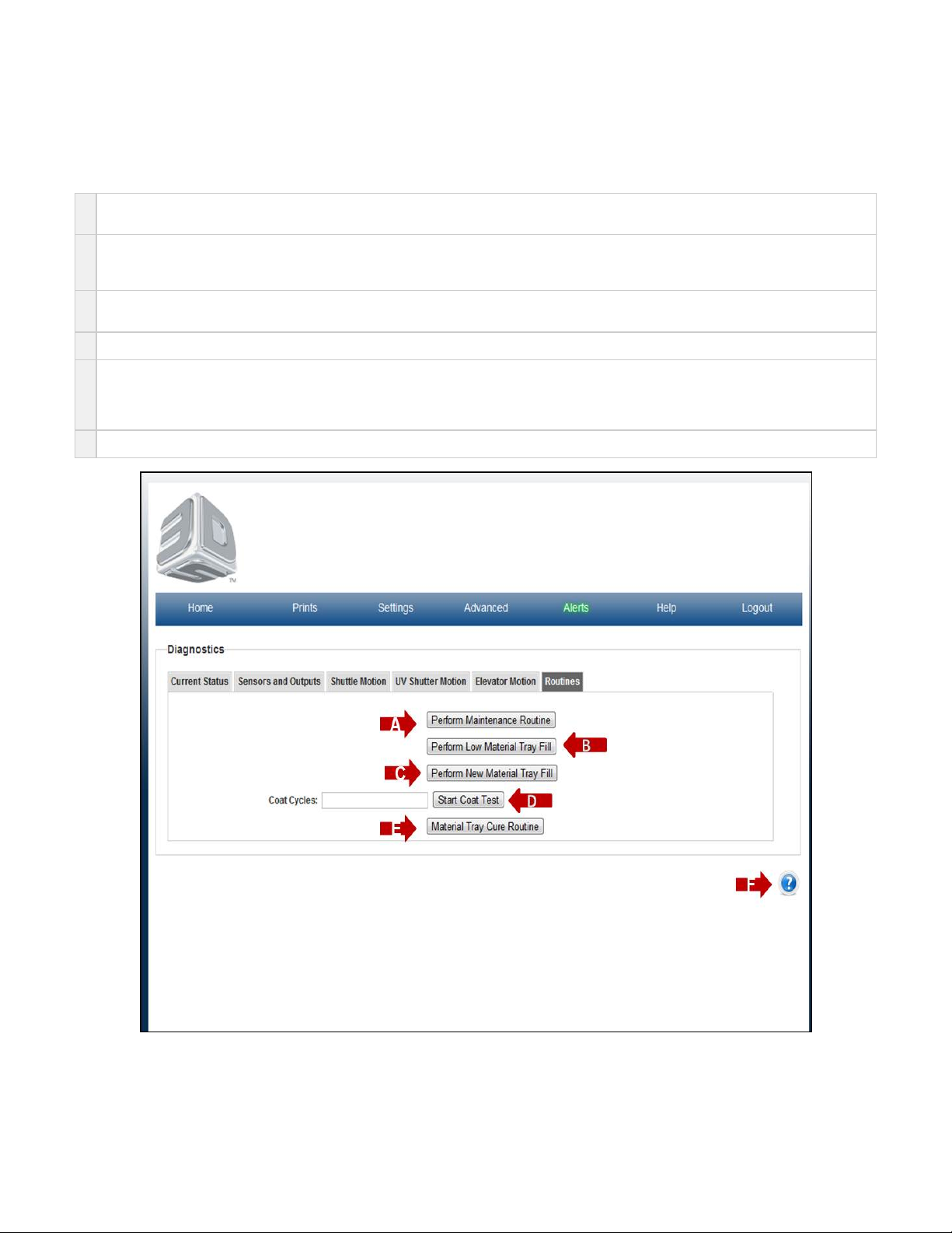
Routines
On the "Home" page, click on "Advanced" and select "Diagnostic" in the drop down menu to view "Routines" screen.
The purpose of the Shuttle Motion page is to allow the user to open, close and home the UV Shutter door.
A
Perform Maintenance Routine enables the shuttle assembly to move back and forth to remove any excess debris that may be in the tray.
NOTE: If a large piece of debris is in the tray, unlock the door, lift the shuttle tray and remove with gloves or a putty knife.
B
Perform Low Material Tray Fill Routine enables the printer to perform a routine to add material to a low material tray. Do not over fill
material tray.
NOTE: There is a limit to 4-fills to protect against overflowing the material tray.
C
Perform New Material Tray Fill Routine enables the printer to perform a routine to fill a new material tray.
NOTE: The material tray MUST be empty or near empty or this could overflow the material tray.
D
Start Coat Test enables the printer to perform a routine to coat the material tray. The user must input the number of cycles.
E
Material Tray Cure Routine enables the printer to cure material in material tray before disposing of material tray in alignment with local
standards.
NOTE: Once you perform this routine, the current material tray will no longer be capable of printing. Please discard following the
instructions provided by 3DSystems.
F Click on the to obtain help for this particular screen.?
Page 74

Sensors and Output
On the "Home" page, click on "Advanced" and select "Diagnostic" in the drop down menu to view "Sensors and Ouput" screen.
The purpose of the Sensors & Outputs page is to provide feedback from various sensors and provides the ability to toggle some of the system
hardware on and off.
A
Ambient Pump Count is measured count when printer is powered on.
B
Vacuum Pump Count is measured count when printer is in vacuum mode. The Vacuum Pump Count should be ~150 count below Ambient
Pressure.
C
Puff Pump Count is measured count when printer is in puff mode. This value is always <100 count above Ambient Pump Count.
D
Cover Lock is on / off toggle that reports the current state of the Cover Lock. If checked, the cover is locked. If unchecked, the cover should
be unlocked.
E
Film Vacuum is on / off toggle that reports the current state of the Film Vacuum. If checked, the film pump should be providing vacuum
(negative pressure on the imaging surface of the material tray).
F
Film Puff is on / off toggle that reports the current state of the Film Puff. If checked, the film pump should be providing puff (positive
pressure on the imaging surface of the material tray).
G
UV Sensor- Measured count of UV light.
H
Load cell is the measured count of cartridge load at sensor.
I
Material Weight(g)- Measured weight in grams of material in cartridge.
J
Cover open is a checkbox that reports the status of the System Cover.
K
Fans - Build Speed is an on / off toggle that reports the current state of the Fans on the system. If checked, the Fans will be running as
build speed (faster).
L
Fans - Idle Speed is an on / off toggle that reports the current state of the Fans on the system. If checked, the Fans will be running as idle
speed (slower).
M
Imager Power is an on / off toggle that reports the current state of the Imager Power. If checked, the imager has power and can be turned
on. If Imager on is checked as well, the imager will emit light.
N
Imager On is an on / off toggle that reports the current state of the Imager. If checked, and the imager power is checked as well, the imager
will emit light. The light will only be visible in the print chamber if the UV shutter is opened. SAFETY NOTICE: The Imager emits UV Light
which can be hazardous to your vision. Please use caution and the properly recommended UV Safety glasses if opening the print
chamber with the imager turned on. This is only intended to be a troubleshooting tool.
O Click on the to obtain help for this particular screen.?
Page 75
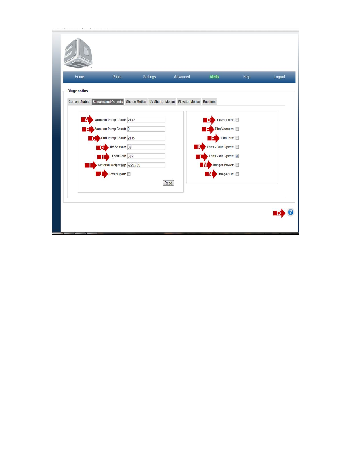
Page 76
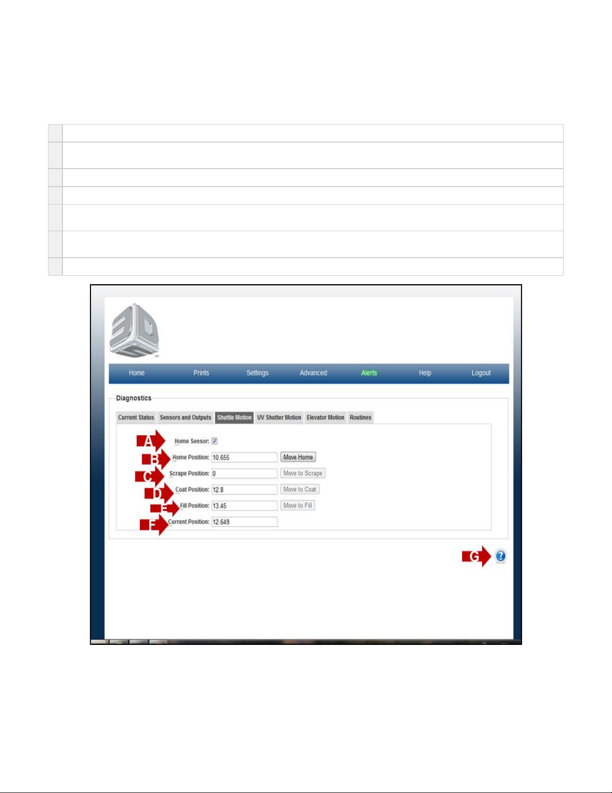
Shuttle Motion
On the "Home" page, click on "Advanced" and select "Diagnostic" in the drop down menu to view "Shuttle Motion" screen.
The purpose of the Shuttle Motion page is to allow for the user to correct shuttle errors, and to manually home the shuttle, or fill the tray.
A
Home Sensor is a readout of the sensor HW when manually enabled.
B
Home Position will allow for the shuttle to move to home position from any other position. If encoder position is lost due to a failure, this is
used to regain the shuttle home. Accompanying readout is a target.
C
Scrape Position is the position to the front of the material tray or front of printer. Accompanying readout is a target.
D
Coat Position is the position to move too, in order to coat or recoat the material tray with material. Accompanying readout is a target.
E
Fill Position is the position to move to in order to actuate the cartridge valves and add material to the material tray. Accompanying readout
is a target.
F
Current Position is a readout of the current position. Note the values do not have units. Each move has a tolerance of ~0.100 and is not
cumulative.
G Click on the to obtain help for this particular screen.?
Page 77
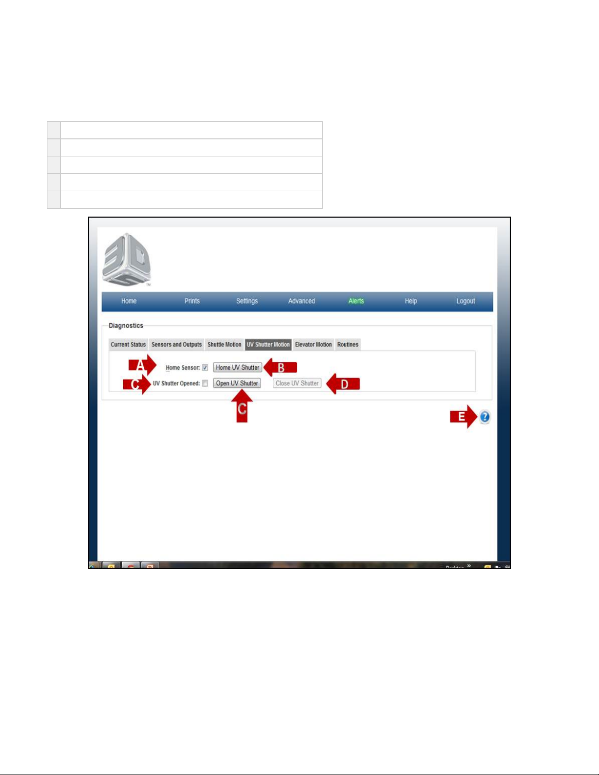
UV Shutter Motion
On the "Home" page, click on "Advanced" and select "Diagnostic" in the drop down menu to view "UV Shutter Motion" screen.
The purpose of the Shuttle Motion page is to allow the user to open, close and home the UV Shutter door.
A
Home Sensor is a readout of the sensor HW when manually enabled.
B
Home UV Shutter is a routine to home and close the UVShutter door.
C
Open UV Shutter opens the UVShutter door to open operating position
D
Close UV Shutter closes the UVShutter door to closed operating position.
E Click on the to obtain help for this particular screen.?
Page 78
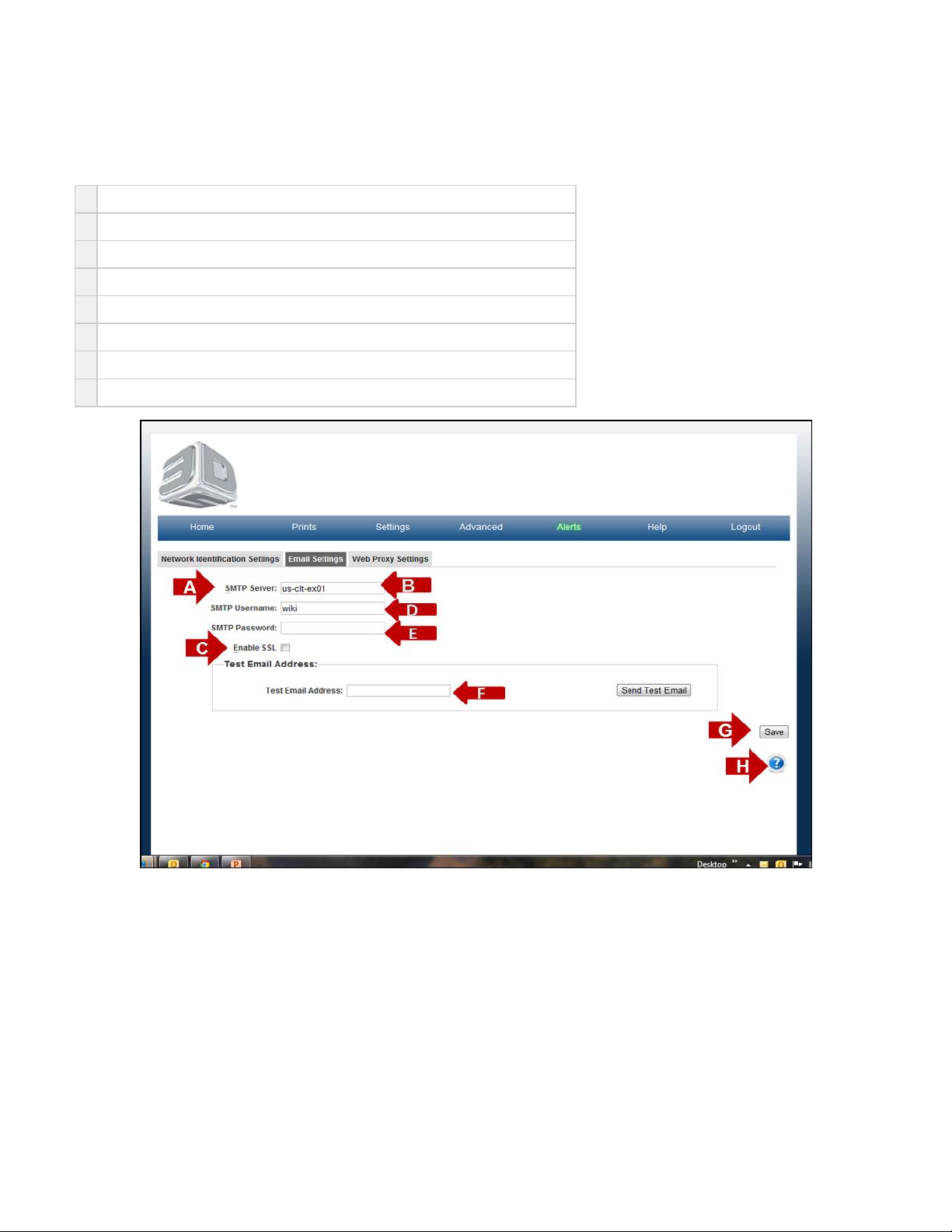
Email Settings
On the "Home" page, click on "Settings" and select "Printer" in the drop down menu to view "Email Settings" screen.
The purpose of the Email Setting is to set your email account to the correct browser to receive email notifications.
A
Find your POP3/SMTP mail settings from your email client.
B
Enter your (Outgoing Mail) SMTP server name in the SMTP Server field.
C
If your server requires TLS, STARTTLS, or SSL then check the "Enable SSL" option.
D
Enter your Account name in the SMTP Username field.
E
Enter your Password in the SMTP Password field.
F
Send a test email to your PC.
G
Click Save to retain your information.
H Click on the to obtain help for this particular screen.?
Page 79
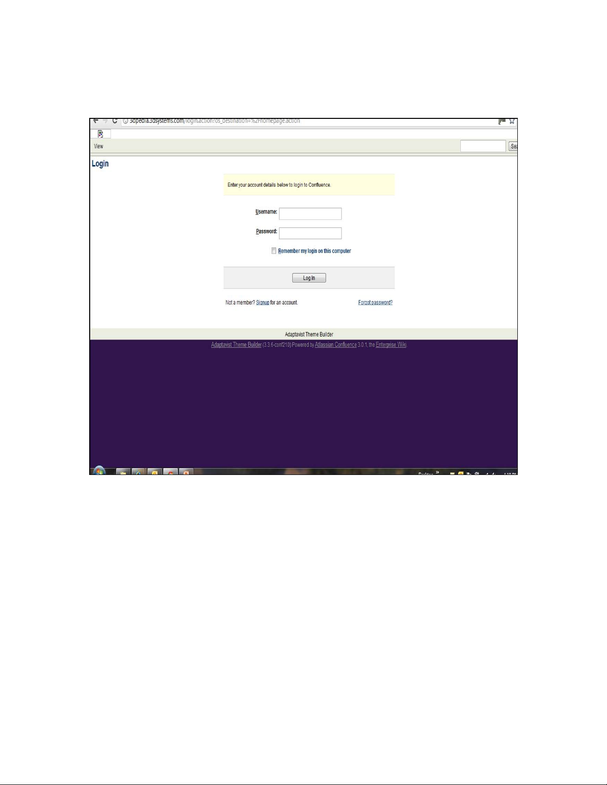
Help
On the "Home" page, click on "Help" menu. The Help menu will link you to 3dpedia to view other documentation. Once at 3dpedia login page,
enter pj15k for both user name and password; click on login to gain access to 3dpedia.
Page 80
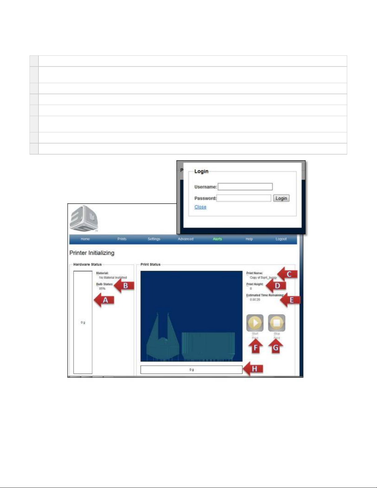
Home Page
A
Material: shows how much material is in cartridge.
B
Bulb Status: shows current bulb energy status. When this gets to 50%, you will be prompted to change the bulb for better performance
printer performance.
C
Print Name: name of current print being printed
D
Print Height: the current height the print is built to. It will increase with the print until the print is complete.
E
Estimated Time Remaining:is the current time left to complete the print. Unit are in hr., min., sec.
F
Start: used to start the print. This button is changed to Pause after the build begins and back to Start after the build is completed. Pause
allows build to be restarted
G
Stop: does NOT allow for print to restart. It will abort the print job that is currently printing.
H
Build: Consumption is the dynamic cumulative amount of material used. Just hold mouse over weight and get popup.
Page 81
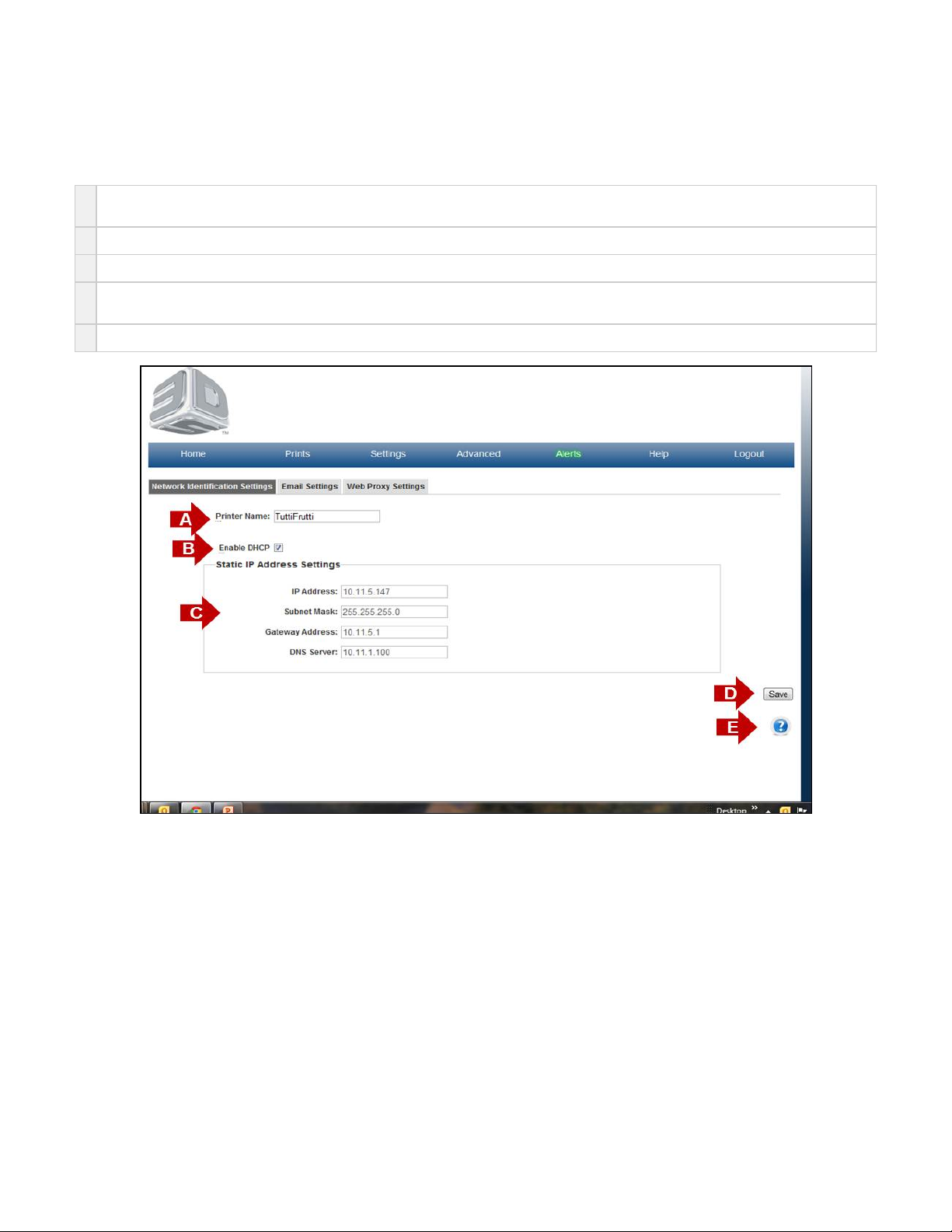
Network Identification Settings
On the "Home" page, click on "Settings" and select "Printer" in the drop down menu to view "Network Identification Settings" screen.
The purpose of the Network Identification Settings is to identify your printer network settings.
A
Printer Name- If the system administrator chooses to do so, they can change the system name to one that they desire. This requires a
printer reboot to take effect..
B
Enable DHCP is default setting for the printer. This allows for client PC to easily access and assign IP address to communicate with printer.
C
Static IP Address Settings are automatically filled in for Enable DHCP printers.
D If a user desires static IP Address settings, then Uncheck the Enable DHCP box ; fill in correct information for desired static settings.(B)
Save button will save any settings that you have implemented.
E Click on the to obtain help for this particular screen.?
Page 82
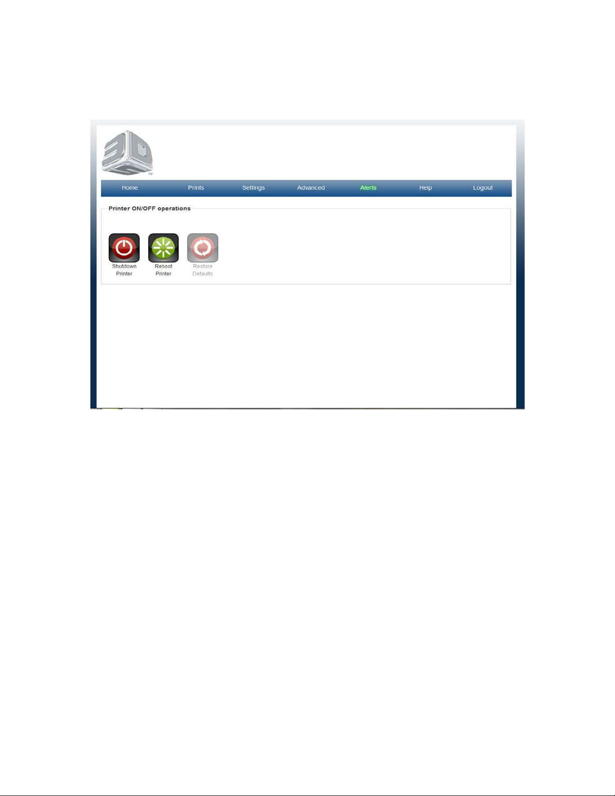
Printer ON-OFF
On the "Home" page, click on "Advanced" and select "Printer On/OFF" in the drop down menu to view "Printer Operations" screen.
The purpose of the printer operations is to shutdown ir reboot printer or to restore printer's default.
Page 83
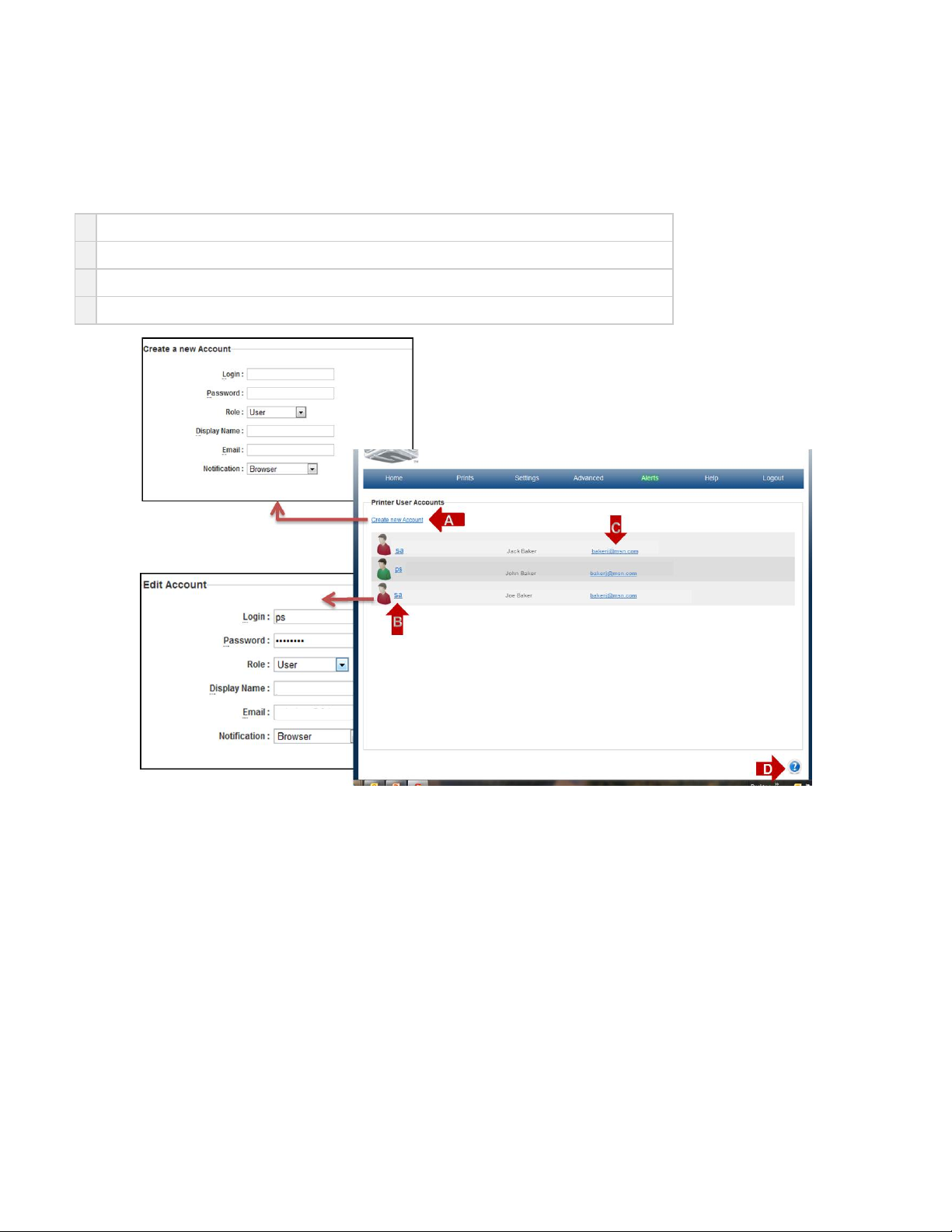
Printer User Account
On the "Home" page, click on "Settings" and select "Users" in the drop down menu to view "Printer User Account" screen.
The purpose of the Uuser page is to list all registered users for the printer. This is the place all user data is added, and removed after a printer has
been registered.
A
Create New Account link allows for new users to be added by going to a USER Account page.
B
The link by each user icon allows for a user to edit user information or to delete a user form the printer.
C
The email link opens the default email system on the client PC to send an email.
D Click on the to obtain help for this particular screen.?
Page 84
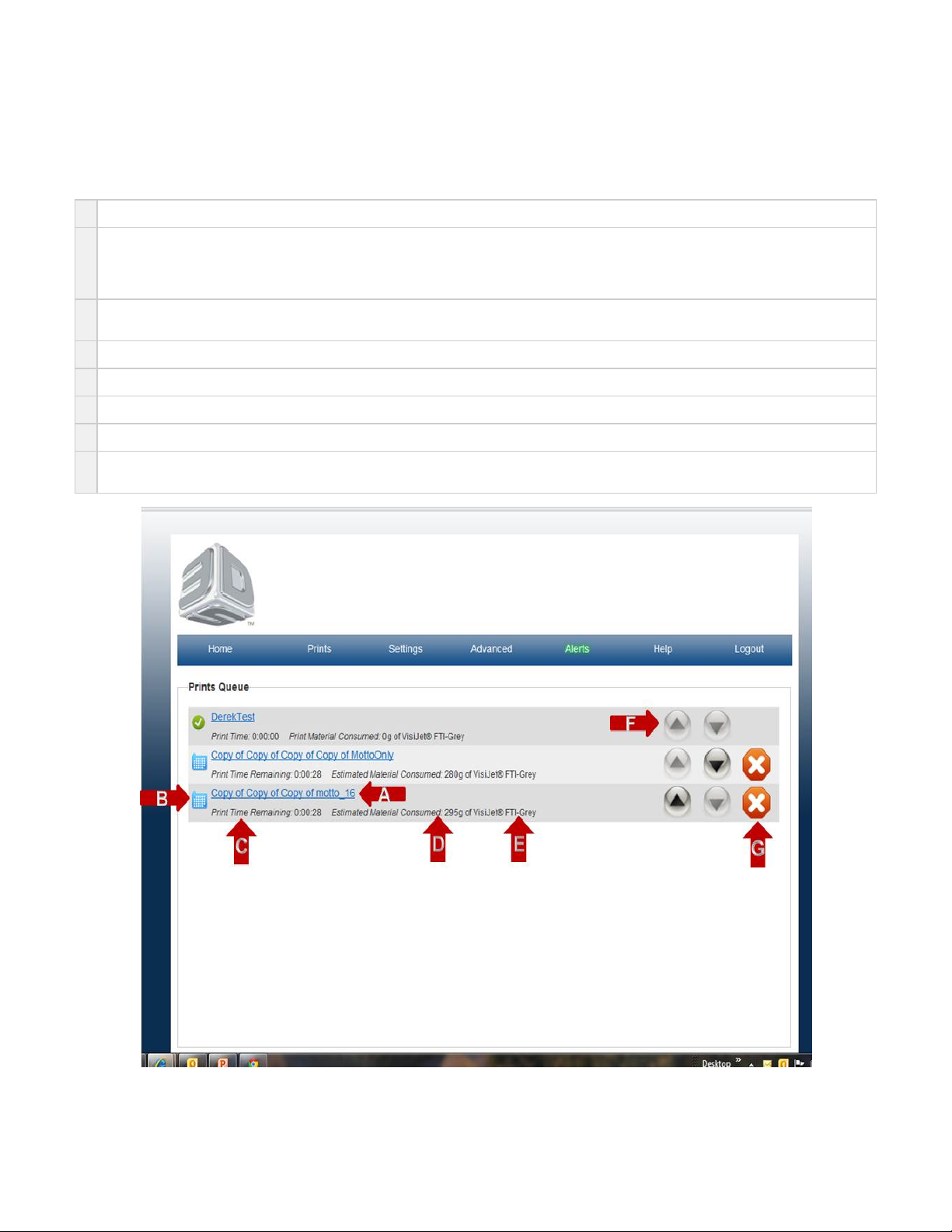
Prints Queue
On the "Home" page, click on "Prints" and select "Queue" in the drop down menu to view "Prints Queue" screen.
The purpose of the Prints Queue page is to provide a list of all available prints created on your printer. The list also provides specific information
for each print.
A
Link in blue is the Print Name given by the user.
B Next to each Print Name is one of four icons: spinning status circle shows a print that is currently being printed or Active iconYellow
icon shows a print that is not active, but waiting in the queue or Queue iconBlue Matrix
mark shows print that has completed, and waiting to be removed form the printerGreen check
Triangle shows print that is aborted or Aborted icon.Red
C
Estimated Print Time-If the print has the Active Icon then the time shown is the estimated time left in the print to completion.
If the print has the Queue icon then the time shown is an estimate of the complete time of the print.
D
Print Material used- This only is given for the Active icon, and shows the current amount of material used thus far in the print.
E
Estimated Print Material used is an estimate of the amount of material to be used in the given print.
F
Each Print name also has the print material the print was created to build listed underneath.
G Up\Down arrows allow for prints to be prioritized in the queue. Note: that a print that has already started may not be moved.
G The red is used to Delete a print. When pressed the User will be prompted to acknowledge that choice before the printer will execute theX
abort.
Page 85
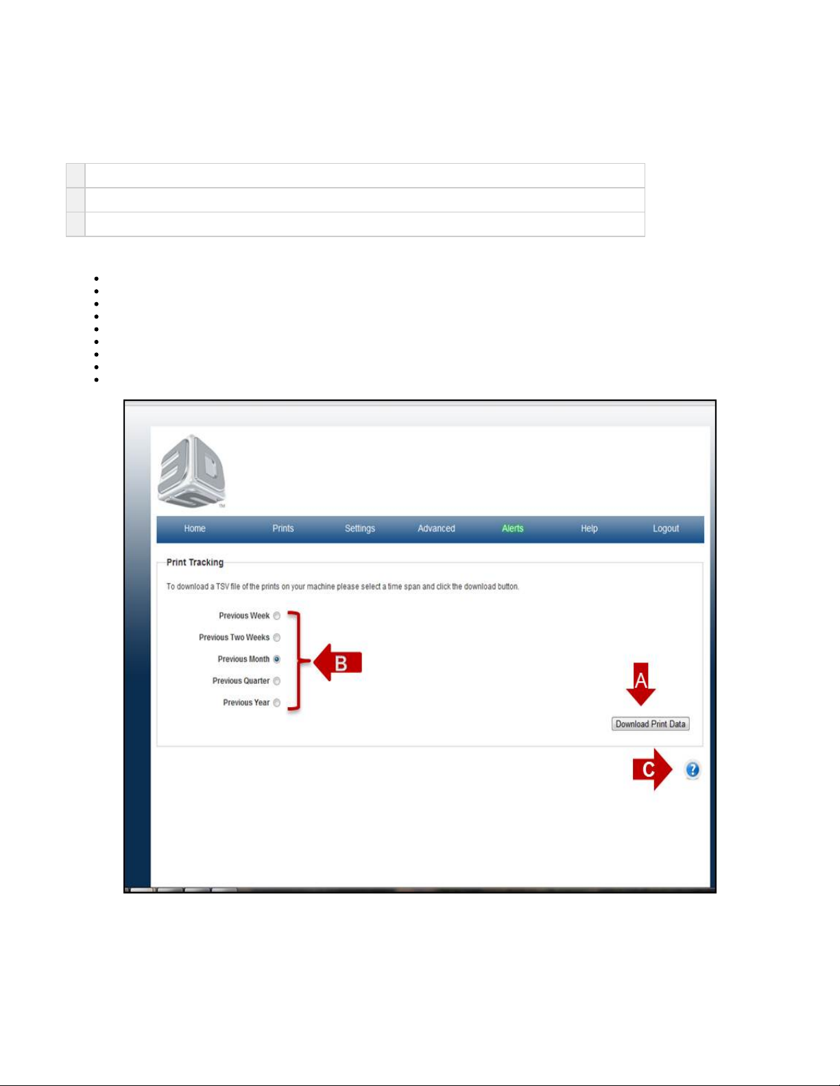
Print Tracking (TSV Report)
On the "Home" page, click on "Print" and select "Tracking" in the drop down menu to view "Print Tracking" screen.
The purpose of the Print tracking page is to allow for the user to open and view a history of prints on the printer.
A
The information can be retrieved by pressing the Download Data button and opening the TSV file in spreadsheet.
B
The data can be retrieved from durations of Previous Week up to Previous Year.
C Click on the to obtain help for this particular screen.?
The information on the print tracking page are indentified in following catagories:
Print Name
Print Submitter
Project
Print State
Start Time
Duration- time for build to complete
Material- type of material
Material used- Amount (mL)
Height (in)
Page 86
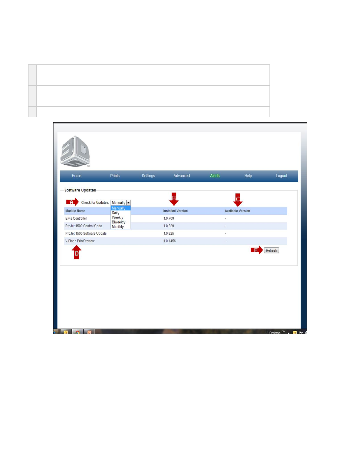
Software Updates
On the "Home" page, click on "Advanced" and select "Softwarer Updates" in the drop down menu to view available software.
A
Check for updates can be set manually or daily through monthly.
B
Installed Versions show the version of software previously donloaded to you printer.
C
Available Versions are new releases of software. The link will be shown in blue. Click on the link to download.
D
Module Name is the software name and type of software that has previously been downloaded to your printer.
E Click on the to obtain help for this particular screen.?
Page 87
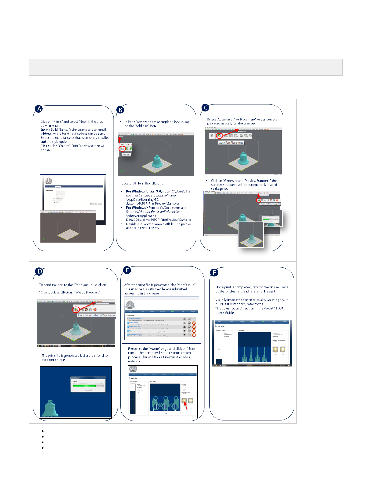
08. Operations
NOTE:After each print, the printer must be clean to ensure that there is no debris or material residue left on the image plane glass
and inside of chamber.
To ensure the set-up is correct and the printer is performing properly, a "Test Print" is recommended. Please follow the operation instructions
to create your first print.
08.1 Print Process & Previewing Print
08.2. Delete a Print
08.3. Part Removal & Cleaning Procedure
08.4. Shutting Down System
Page 88

08.5. Alert Messages
08.6 Printer LED Status Lights
Page 89
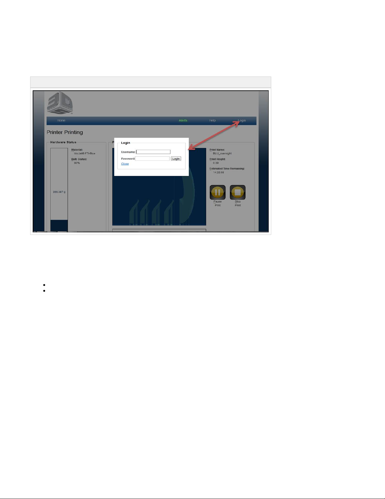
08.1 Print Process & Previewing Print
Before starting to your print, preparing the printer for a print must be accomplished. Please refer to and complete the06.4 Printer Preparation
steps before printing.
Login to the printer to begin the print process.
08.1.01 Create a New Print
08.1.02 Submitting a Print to Print Preview
08.1.03 Previewing Prints
8.1.03.1 Print Preview
8.1.03.2 Preview Browser Overview
08.1.04 Save a Print
Page 90
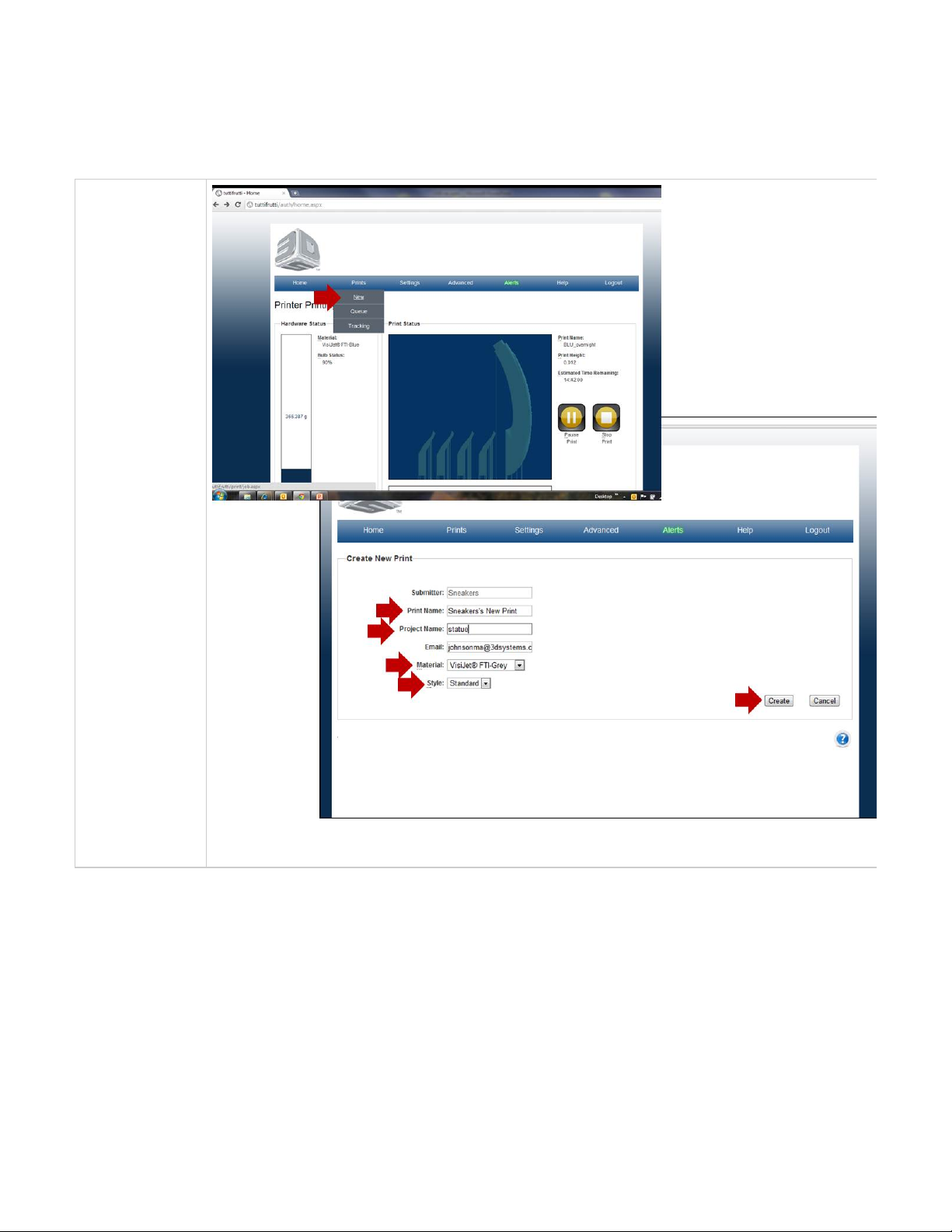
1.
2.
3.
4.
5.
6.
7.
08.1.01 Create a New Print
To create a print, a print name and project name has to be assigned before a print can be viewed in Print Preview. Follow the instructions to start
the print process.
Create a
Print Name
for the part
that is being
submitted.
Assign a
Project
.Name
Select the
forMaterial
the print.
Select the
Style
"Standard"
or "Draft.
Click on
"Create" to
submit your
print to Print
Preview.
Print
Preview will
allow you to
manipulate
part on the
print
platfrom. It
also allows
you to scale,
rotate and
automatically
place part on
the platform.
Submit build
by selecting
"Submit"
button.
Slicing will
begin and
the job will
be sent to
the build
queue
without it
being saved.
Page 91
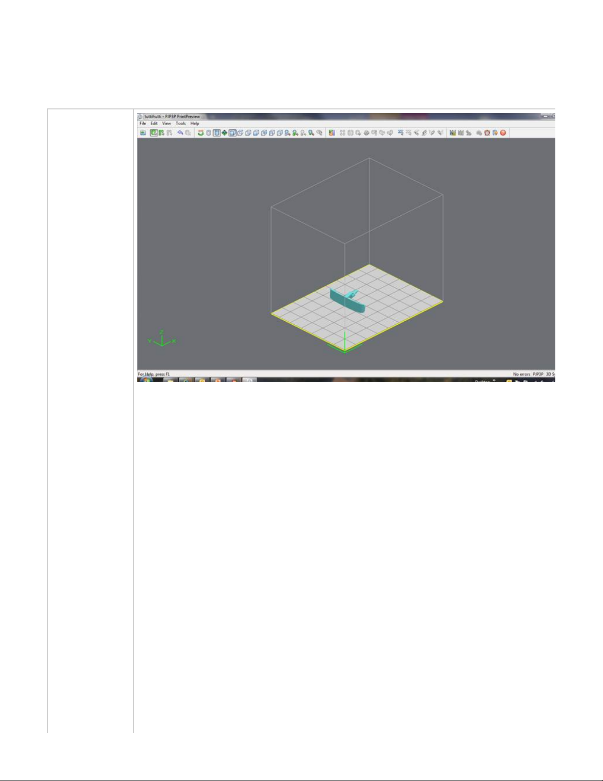
1.
2.
08.1.02 Submitting a Print to Print Preview
Submit a Print
Add part(s) to
Print Preview
by addinga
STL files onto
the preview's
platform. This
is a
simulation of
the actual
printer's
platform.
Parts can be
scaled,
rotated,
mirrored, and
other various
manipulations
to ensure that
the part prints
correctly.
Page 92

3. Parts will be
sliced in Print
Preview
before it is
sent to the
printer's
queue.
NOTE: Parts
will shrink in
X and Y. The
degree of
shrinkage
depends on
print
geometry.
3D Systems
recommends
that the
default value
should be
used until the
user has
enough
experience or
collects
enough data
to determine
that different
values are
needed.
NOTE:
Shrink
Comp % is
not the
same thing
as "scaling"
a print. Do
not use
Shrink
Comp % to
change the
final size of
the print.
Rather, use
Shrink
Comp % to
compensate
for size and
shape
changes
that happen
as a result
of the 3-D
modeling
process.
Tips on Submitting Prints
To select more than one STL file In the dialog box, hold down the Ctrl key and click on several STL files.
To add parts in the window: After adding STL file (s), using the window, view the job in three dimensions and add morePreview Preview
STL files if desired.
Page 93

08.1.03 Previewing Prints
Print Preview Installation
Previewing enables you to see a three-dimensional view of the print. It is used to change the rotation or arrangement of STL, and to add
additional file.
8.1.03.1 Print Preview
Moving and Placing Parts
Part Colors in the Viewing Area
8.1.03.2 Preview Browser Overview
Add Parts
Align Parts Facings
Auto Place
Back View
Bottom View
Confirming part units
Copy
Create Job and Return to Web Browser
Delete
De-Select all
De-select All Triangles
Display Support Creation Surface
Edit Supports
Estimate Build Time
Front View
Generate and Preview Supports
Help Topics
Isometric View
Left View
Mirror
Right View
Rotate
Scale
Scale inch to mm
Scale mm to inch
Select All
Selected Part Information
Selected Parts
Select part
Shaded Display
Top View
Trackball View
Translate
Triangle Selection
Undo
Undo Zoom
Verify
View All Parts
View Platform and Parts
Wire Frame
Zoom
Page 94

8.1.03.1 Print Preview
Moving and Placing Parts
Requirements for Moving Parts with the Pointer
System Coordinates
Part Colors in the Viewing Area
Page 95

Moving and Placing Parts
You can move parts by dragging them with the pointer, or by specifying a new location in a dialog box. You can also automatically place parts. In
all cases, parts can only be moved in the X and Y planes. Parts cannot be stacked, and the Z location of parts is automatically set by the system.
Also See:
Requirements for Moving Parts with the Pointer
System Coordinates
Page 96

Requirements for Moving Parts with the Pointer
To move parts with the pointer, you must:
use the Top or Bottom view of the viewing area
have the selection pointer selected
When these requirements are satisfied, you can drag parts to a desired location within the build envelope.
Page 97
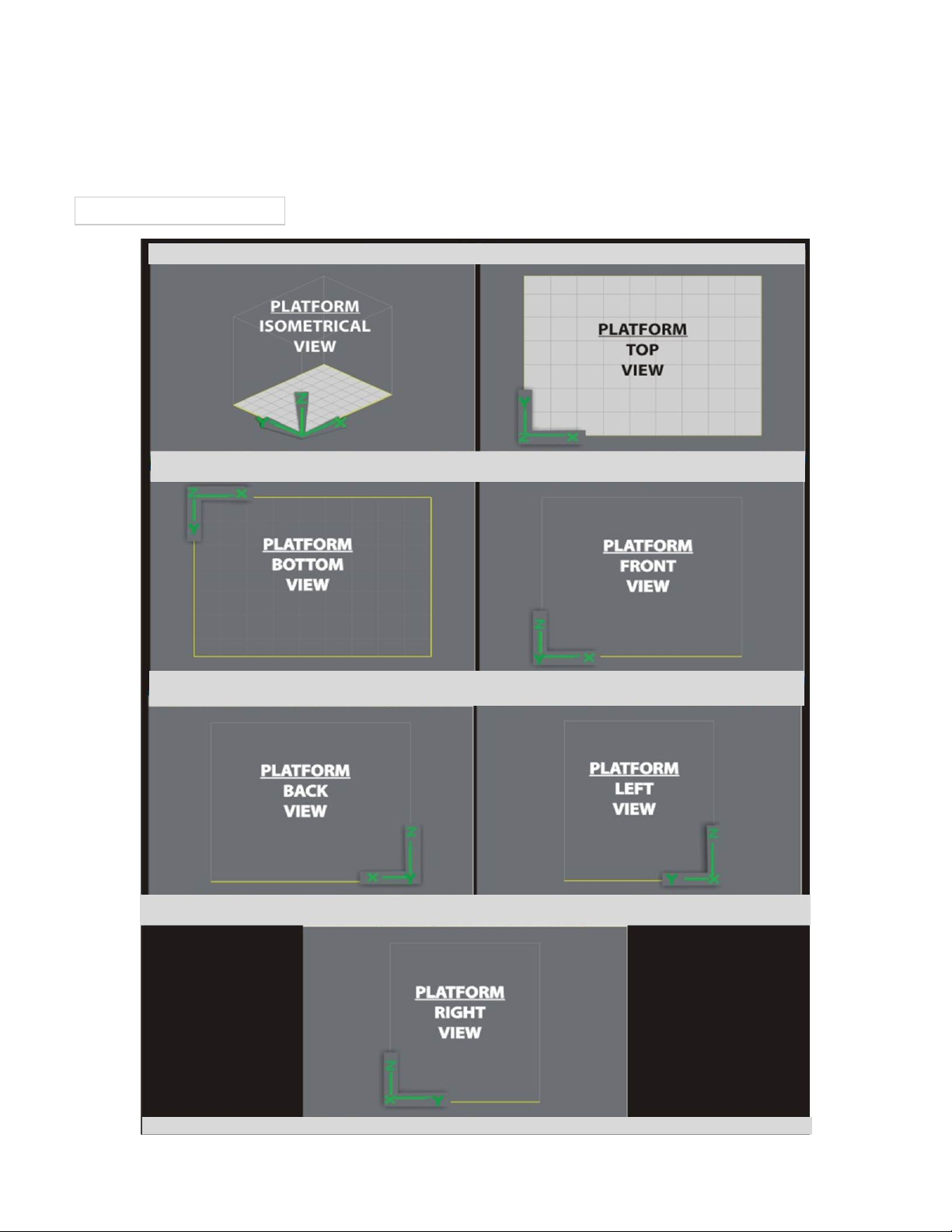
System Coordinates
The system uses X, Y, and Z coordinates to place STL files in the build area.
The diagram shows how the coordinate axes are arranged. Note that the Y axis, rather than the X, is the one that faces you, and the Z axis
increases as the print platform is . Also note that the 0,0,0 location is the upper left corner of the build pad.lowered
Print Envelope X,Y,Z Coordinates
Page 98
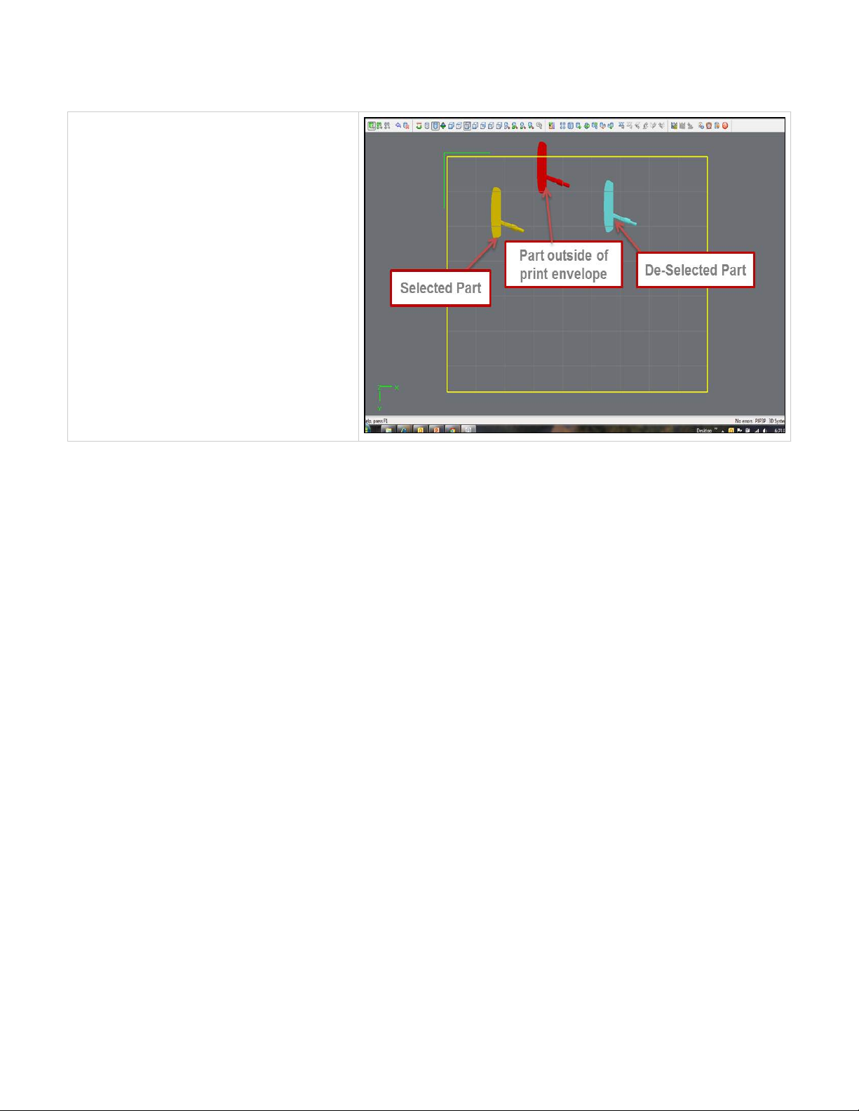
Part Colors in the Viewing Area
Parts are displayed in shades of green or blue when
they are within the build envelope, and in red when they
are not. Selected parts are displayed in yellow within the
build envelope, and in orange when not
Page 99
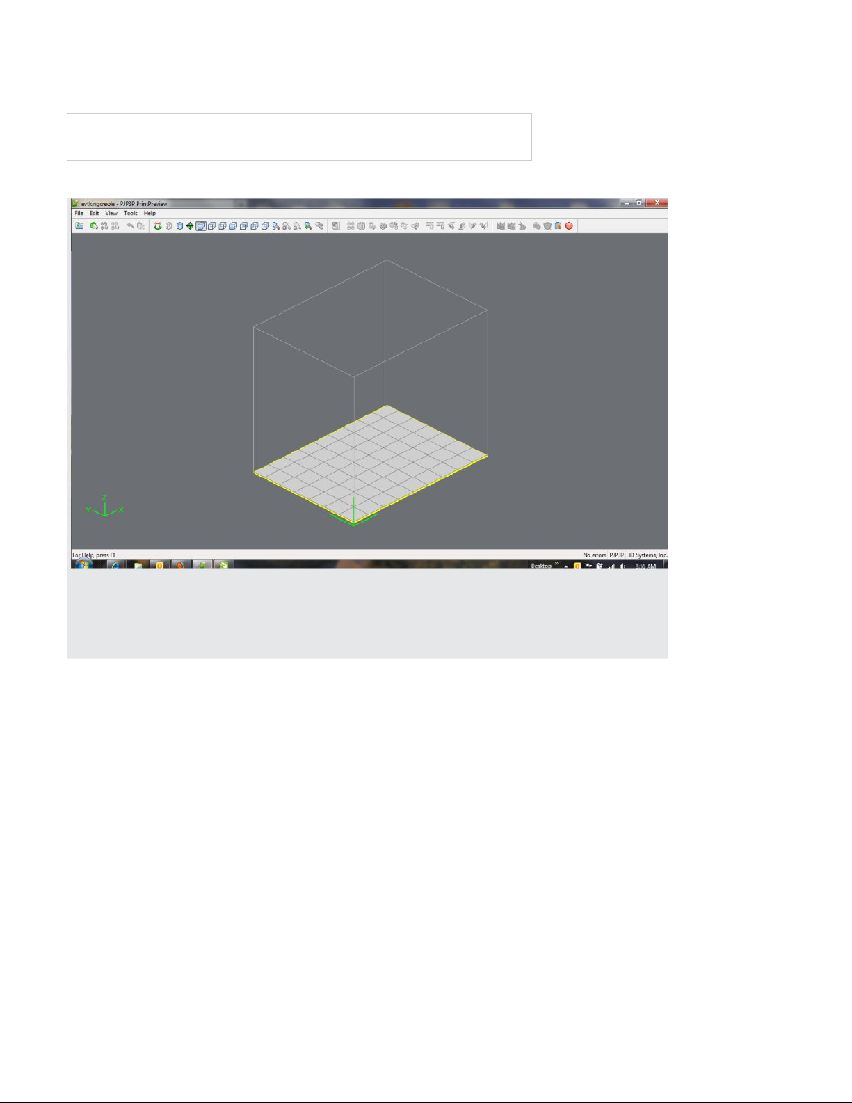
8.1.03.2 Preview Browser Overview
Click on the icons located on the top of the print preview screen to identify their functions.
Page 100
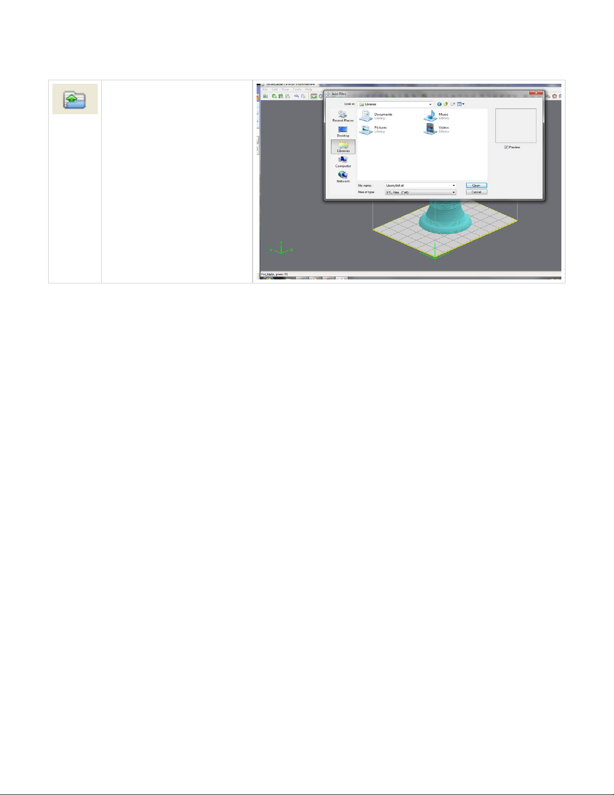
Add Parts
To add a part, click the buttonAdd Part
or select .File, Add a STL or CTL File
The system displays a file browser
dialog box which you can use to select
one or more parts. After selecting the
parts, the system adds them to the
model job and and sets the parts to a
specific Z location.
Click here to return to Print Preview Browser
 Loading...