


INTELLI-RV
12V POWER MANAGEMENT SYSTEM
P/No. PM300

IMPORTANT SAFETY INFORMATION
Please read this manual thoroughly before use and store in a safe place for future reference.
WARNINGS
ß ([SORVLYHJDVHV 3UHYHQWöDPHVDQGVSDUNV 3URYLGHDGHTXDWHYHQWLODWLRQGXULQJFKDUJLQJ
•Before charging, read the instructions
•For indoor use. Do not expose to rain
ß )RUFKDUJLQJOHDGDFLGEDWWHULHV21/< RIWKHVL]H YROWDJHVSHFLõHGLQWKHVSHFLõFDWLRQVWDEOH
•Always charge the battery on the correct voltage setting. Never set the charger to a higher voltage than the battery
ß 'LVFRQQHFWWKH 9PDLQVVXSSO\EHIRUHPDNLQJRUEUHDNLQJWKHFRQQHFWLRQVWRWKHEDWWHU\ ß 7KHEDWWHU\FKDUJHUPXVWEHSOXJJHGLQWRDQHDUWKHGVRFNHWRXWOHW
•Connection to supply mains is to be in accordance with National wiring rules
•Do not attempt to charge non-rechargeable batteries
•Never charge a frozen battery
•If the AC cord is damaged, do not attempt to use. It must be replaced or repaired by a
TXDOLõHGSHUVRQ
•Corrosive substances may escape from the battery during charging and damage delicate surfaces. Store and charge in a suitable area
ß 7KLVFKDUJHULVQRWLQWHQGHGIRUXVHE\SHUVRQV LQFOXGLQJFKLOGUHQ ZLWKUHGXFHGSK\VLFDO VHQVRU\RUPHQWDOFDSDELOLWLHV RUODFNRIH[SHULHQFHDQGNQRZOHGJH XQOHVVWKH\KDYHEHHQ given supervision or instruction concerning the use of the appliance by a person responsible for their safety
• Young children should be supervised to ensure that they do not play with the appliance
2

CONTENTS
1. INTRODUCTION |
4 |
|
1.1 |
Features |
5 |
1.2 |
Monitor |
6 |
:DWHUWDQNSUREH |
|
|
2. KEY FEATURES AND FUNCTIONS |
6 |
|
2.1 |
Multiple inputs |
6 |
2.2 |
Battery charger of stationery/service battery |
6 |
2.3 |
Vehicle battery charger |
7 |
2.4 |
Power supply mode |
7 |
2.5 |
MPPT solar charger controller |
7 |
|
9ROWDJHFKDUJLQJUHOD\ 9&5 |
|
2.7 |
Categorised outputs |
8 |
2.8 |
Battery low voltage protection |
8 |
2.9 |
Manual battery switch |
8 |
2.10 Precise battery measurement |
8 |
|
2.11 Silent mode |
8 |
|
3. STRUCTURE AND INSTALLATION |
9 |
|
3.1 |
PM300 Power Management System |
9 |
3.2 |
Monitor |
10 |
:DWHUWDQNSUREH |
|
|
30:6 ZDWHUWDQNSUREH |
|
|
30:6 ZDWHUWDQNSUREH |
|
|
4.WIRING |
12 |
|
4.1 |
Material |
12 |
4.2 |
System schematic |
13 |
4.3 |
Preparation |
14 |
4.4 |
Connection |
14 |
5. DISPLAY |
15 |
|
5.1 |
PM300 Master Power Unit |
16 |
5.2 |
Monitor |
16 |
5.2.1 Monitor symbol explanation |
16 |
|
5.2.2 Switch explanation |
17 |
|
5.2.3 Alphabet explanation |
17 |
|
6. OPERATION |
18 |
&RQõJXUDWLRQRQ30 |
|
6.1.1 Battery capacity and battery type |
18 |
6.1.2 Select switch local/remote |
19 |
&RQõJXUDWLRQRQPRQLWRU |
|
0RQLWRUFRQõJXUDWLRQPHQX |
|
6.3 Maintenance |
21 |
6.3.1 Battery monitor maintenance |
21 |
6.3.2 Daily maintenance |
21 |
7.TROUBLE SHOOTING |
22 |
|
7.1 |
L.E.D Display on PM300 Unit |
22 |
7.2 |
Error code on monitor |
22 |
8. SPECIFICATION |
23 |
|
3
1. INTRODUCTION
30 LVGHVLJQHGIRUXVHLQFDUDYDQVRUPRWRUKRPHV 7KHXQLWKDVLQWHJUDWHGIXQFWLRQVVXFKDV EDWWHU\FKDUJHU GLVWULEXWLRQEORFNV 0337VRODUFKDUJHUFRQWUROOHU FKDUJLQJUHOD\ /RZ9ROWDJH'LVFRQQHFW /9' ZDWHUSXPSFRQWUROOHU ZDWHUWDQNLQGLFDWRUDQG/&'
Display.
The PM300 is designed for an easy installation and a user-friendly interface.
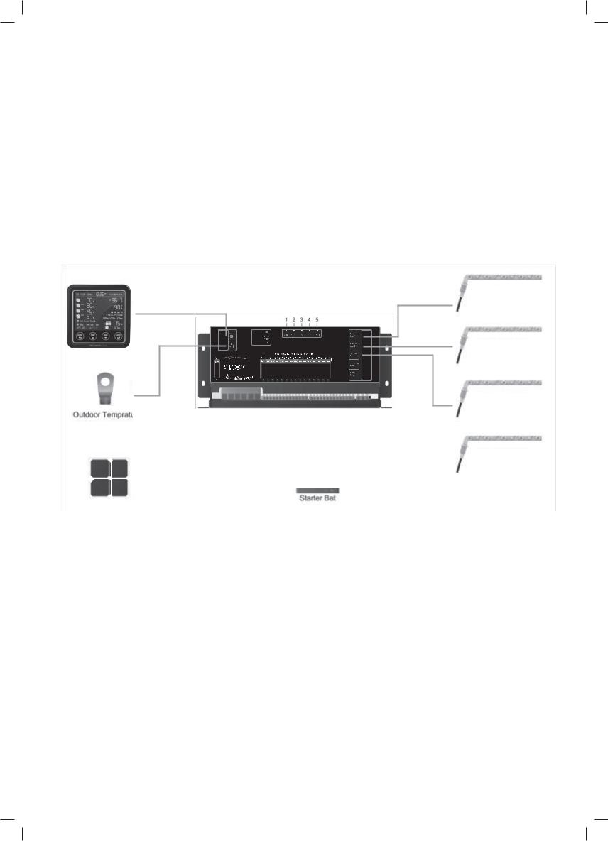
SYSTEM COMPONENTS:
1.Master Power Unit
2.Monitor
:DWHUWDQNVHQVRUV 1RWVXSSOLHG&DEOHV 5HIHUWR&KDSWHU IRUWKHFDEOHOLVW
P/No. PMLCD
P/No. PM335
|
|
|
|
|
|
|
|
|
|
|
|
|
|
|
|
|
|
|
|
|
|
|
|
|
|
|
|
|
|
|
|
|
|
|
|
|
|
|
|
|
|
|
|
|
|
|
|
|
|
|
|
|
|
|
|
|
|
|
|
|
|
|
|
|
|
|
|
|
|
|
|
|
|
|
|
|
|
|
|
|
|
|
|
|
|
|
|
|
|
|
|
|
|
|
|
|
|
|
|
|
|
|
|
|
|
|
|
|
|
|
|
|
|
|
|
|
|
|
|
|
|
|
|
|
|
|
|
|
|
|
|
|
|
|
|
|
|
|
|
|
|
|
|
|
|
|
|
|
|
|
|
|
|
|
|
|
|
|
|
|
|
|
|
|
|
|
|
|
|
|
|
|
|
|
|
|
|
|
|
Outdoor Temperature |
|
|
|
|
|
|
|
|
|
|
|
|
|
|
|
|
|
|
|
|
|
|
|
|
|
|
|
|
|
|
|
||||
|
|
|
|
|
P/No. PM335 |
|
|
|
|
|
|
|
|
|
|
|
|
||||||||||||||||||
|
|
|
|
|
|
|
|
|
|
|
|
|
|
|
|
|
|
|
|
|
|
|
|
|
|
|
|
|
|
|
|
|
|
|
|
P/No. PM10 |
|
|
|
|
|
|
|
|
|
|
|
|
|
|
|
|
|
|
|
|
|
|
|
|
|
|
|
|
|
|
|
||||
|
|
|
|
|
|
|
|
|
|
|
|
|
|
|
|
|
|
|
|
|
|
|
|
|
|
|
|
|
|
|
|
|
|
|
|
|
|
|
|
|
|
|
|
|
|
|
|
|
|
|
|
|
|
|
|
|
|
|
|
|
|
|
|
|
|
|
|
|
|
|
|
|
|
|
|
|
|
|
|
|
|
|
|
|
|
|
|
|
|
|
|
|
|
|
|
|
|
|
|
|
|
|
|
|
|
|
|
|
|
|
|
|
|
|
|
|
|
|
|
|
|
|
|
|
|
|
|
|
|
|
|
|
|
|
|
|
|
|
|
|
|
|
|
|
|
|
|
|
|
|
|
|
|
|
|
|
|
|
|
|
|
|
|
|
|
|
|
|
|
|
|
|
|
|
|
|
|
|
|
|
|
|
|
|
|
|
|
|
|
|
|
|
|
|
|
|
|
|
|
|
|
|
|
|
|
|
|
|
|
|
|
|
|
|
|
|
|
|
|
|
|
|
|
|
|
|
|
|
|
|
|
|
|
|
|
|
|
|
|
|
|
|
|
|
Battery Temperature |
|
|
||||
|
|
|
|
|
|
|
|
|
|
|
|
|
|
|
|
|
Service Battery |
|
|
|
|||||||||||||||
|
|
|
|
|
|
|
|
|
|
|
|
|
|
|
|
|
|
Sensor P/No. PM30 |
|
|
|||||||||||||||
|
|
|
|
|
|
|
|
|
|
|
|
|
|
|
|
|
|
|
|
|
|
|
|
|
|
|
|
|
|
|
|||||
|
|
|
|
|
|
|
|
|
|
|
|
|
|
|
|
|
|
|
|
|
|
|
|
|
|
|
|
|
|
|
|
|
|
|
|
|
|
|
|
|
|
|
|
|
|
|
|
|
|
|
|
|
|
|
|
|
|
|
|
|
|
|
|
|
|
|
|
|
|
|
|
|
PV |
|
|
|
|
|
|
|
|
|
|
|
|
Starter Battery |
|
|
|
|
|
|
|
|
|||||||||||||
|
|
|
|
|
|
|
|
|
|
|
|
|
|
|
|
|
|
|
|
|
|
|
|
|
|
|
|
|
|
|
|
||||
|
|
|
|
|
|
|
Figure 1 System Components for PM300 |
|
|
||||||||||||||||||||||||||
Fresh Water Tank 1 Probe (Not supplied)
P/No. PMWS200 or PMSW400
Fresh Water Tank 2 Probe (Not supplied)
P/No. PMWS200 or PMSW400
Tap Water Tank Probe (Not supplied)
P/No. PMWS200 or PMSW400
Waste Water Tank Probe (Not supplied)
P/No. PMWS200 or PMSW400
4

1.1 Features
ß 6PDUWEDWWHU\FKDUJHU 9 $ $IRUFKDUJLQJFXUUHQW
• Multi stage adaptive charging algorithm
ß $FWLYH3RZHU)DFWRU&RUUHFWLRQ 3)& FKDUJLQJ
•Temperature compensation charging
•Voltage compensation charging
•Float Charge for starter battery
ß 6RODUFKDUJHFRQWUROOHU 0337 $
•14 built in fused outputs
•Charging from Alternator at 12V 60A - 60A continuously, 100A 30mins
•Low battery voltage protection
•Built-in battery switch to isolate the battery when in storage
•Built-in shunt for precise battery measurement
•1 water pump control with up to 4 connections for water sensors
•Thermal control fan
•Spring terminal and screw terminal
•T-bus compatible
Figure 2 System Schematic
5

1.2 Monitor
The monitor is a digital control center for complete on-board power. Optional Bluetooth module is available for remote monitoring through a smart phone.
FEATURES:
ß 7%XVGHVLJQ FDQEHFRQQHFWHGWRPXOWLSOHGHYLFHV
• System monitoring
ß &RQõJXUDWLRQ
1.3 Water Tank Probe
For PM300, a maximum of 4 probes can be monitored.
Figure 3 Overview of Monitor
NOTE: $OZD\VFKHFNWKHSUREHUHTXLUHGIRUWKHZDWHUWDQNEHIRUHSXUFKDVH
There are 2 probe styles:
PMWS200:
• Side installation
ß 6XLWDEOHIRUZDWHUWDQN
• Depth >200mm
PMWS400:
• Side installation
ß 6XLWDEOHIRUZDWHUWDQN
• Depth 300-400mm
Figure 4 PMWS200
Figure 5 PMWS400
2.KEY FEATURES AND FUNCTIONS
2.1 Multiple Inputs
The PM300 accepts inputs from AC mains, solar panel and starter battery. However, only one source will provide power at one time, see table at right for details:
AC MAINS |
x |
x |
|
|
|
|
|
|
|
|
|
SOLAR |
x |
|
x |
|
|
|
|
|
|
|
|
STARTER |
|
x |
x |
|
|
|
|
BATTERY |
|
|
|
|
|
|
|
DOMINATING |
AC MAINS |
AC MAINS |
STARTER |
SOURCE |
|
|
BATTERY |
|
|
|
|
Table 1 Multiple inputs
2.2 Battery Charger Of Stationery/Service Battery
7KHFKDUJHUDXWRPDWLFDOO\VWDUWVZKHQWKHDSSURSULDWHTXDOLõHGSRZHULVFRQQHFWHG HLWKHUIURPJULG JHQHUDWRURUVRODU
:LWKPXOWLSOHFKDUJLQJVWDJHV VRIWVWDUW EXONDEVRUSWLRQöRDW UHF\FOH 30 LVGHVLJQHGWRIXOO\FKDUJHEDWWHU\TXLFNO\ 7RJXDUDQWHH the optimal charging for batteries of different states, the PM300 features Microprocessor-controlled charging algorithm.The Float and Recycle charging programs guarantees that the battery condition does not change despite being connected for a longer period.
6

|
|
|
|
|
|
|
|
|
|
|
|
|
|
|
|
|
|
|
|
10 days |
1 hr |
5mins |
|||
11.5V |
VOLTAGE |
|
|
|
|
|
|
|
|
|||
|
|
|
|
|
|
|
|
|||||
lcc |
|
|
|
|
|
|
|
|
|
|
|
|
|
|
|
|
|
|
|
|
|
|
|
||
|
|
|
|
|
|
|
|
|
|
|
||
|
|
|
|
|
|
|
|
|
|
|
||
|
|
|
|
|
|
|
|
|
|
|
||
|
|
|
|
|
|
|
|
|
|
|
|
|
|
|
|
|
|
|
|
|
|
|
|
|
|
½ lcc |
CURRENT |
|
|
|
|
|
|
|
|
|||
|
|
|
|
|
|
|
|
|||||
|
|
|
|
|
|
|
|
|||||
STAGE |
|
|
|
|
|
|
|
|
||||
|
|
|
|
|
|
|
|
|||||
SOFT START |
BULK |
ABSORPTION |
FLOAT |
RECYCLE |
||||||||
|
|
|||||||||||
|
|
|
|
1 |
2 |
3 |
4 |
|
5 |
|
|
|
1 |
SOFT START |
|
3 |
ABSORPTION |
|
|
|
|||||
|
|
Increases battery life by gently starting to |
Ensures a full charge to the battery |
|||||||||
|
|
charge the battery 5% of bulk |
|
without overcharging |
||||||||
2 |
BULK |
|
|
4 |
FLOAT |
|
|
|
||||
|
|
Reduces charging time by delivering maximum |
Float charge maintains the battery at |
|||||||||
|
|
charge to set voltage life by gently starting to |
100% charge |
|
|
|
||||||
|
|
charge the battery 25% of bulk |
5 |
RECYCLE |
|
|
|
|||||
|
|
|
|
|
|
|
|
|
||||
Figure 6 Charging Algorithm
Battery Temperature Sensor
7KH%76 31R 30 %DWWHU\7HPSHUDWXUH6HQVRU VXSSOLHGZLWK30 PHDVXUHVWKHWHPSHUDWXUHRIWKHEDWWHU\DQGDXWRPDWLFDOO\DGMXVWV in real time, to charge the battery properly at compensation rate of – 4mv±10%/°C/cell. In case BTS is not present, the PM300 will use 25°C as default.
Voltage Compensation Charging
:LWKDYROWDJHVHQVRUWKH30 FDQ DXWRPDWLFDOO\DGMXVWLWVRXWSXWWRFRPSHQVDWHWKHYROWDJHGURSFDXVHGE\DFDEOH 7KLVDVVXUHVWKH right voltage is being delivered for optimal charging.
$GMXVWDEOH&KDUJLQJ&DSDFLW\
8VHUVFDQDGMXVWWKHFKDUJLQJFXUUHQWE\VSHFLI\LQJWKHEDWWHU\FDSDFLW\ 7KHFKDUJLQJFXUUHQWLVVHWDWWKUHVKROGUDWHRI WKHRIWKH EDWWHU\FDSDFLW\ , & E\GHIDXOW
Lithium Battery Charging
7KH30 FDQEHFRQõJXUHGWRFKDUJH/LWKLXPEDWWHU\ :LWKWKH/LWKLXPEDWWHU\ WKHPD[FKDUJLQJFXUUHQWZLOODXWRPDWLFDOO\EHVHWDWRIEDWWHU\FDSDFLW\ ,PD[ &
2.3 Vehicle Battery Charger
$ORQJZLWKDSRZHUIXOFKDUJHUIRUVHUYLFHEDWWHU\ 30 RIIHUVDöRDWFKDUJHRIXSWR $WRNHHSWKHVWDUWHUEDWWHU\FKDUJHG ZKHWKHU connected to the AC main or PV.When starter battery is less than 12.4V, the PM300 starts charging after 30 minutes delay and stops charging when voltage reaches 12.8V.
2.4 Power Supply Mode
,IQREDWWHU\LVDWWDFKHGWR30 XQLW LWZLOOZRUNDVDSRZHUVXSSO\DXWRPDWLFDOO\ZLWKD 9'&RXWSXW
2.5 MPPT Solar Charger Controller
PM300 has a built-in MPPT charger for the service battery with:
•Max input voltage 50VDC
•Max charging current 20A
•Max supply current 30A
2.6 Voltage Charging Relay (VCR or commonly known as a VSR)
30 PDVWHUSRZHUXQLWKDVDEXLOW LQYROWDJHFKDUJLQJUHOD\ 9&5 ZKLFKRIIHUVDFRQYHQLHQWVRXUFHWRFKDUJHWKHVHUYLFHEDWWHU\E\ alternator whilst engine is running.When the starter battery reaches 13.4VDC with threshold time delay, the VCR will charge the service battery from the alternator.VCR will continue the charging until the starter battery voltage drops under 12.8VDC.
NOTE: 7KH30 ZKHQFKDUJLQJIURPWKHVWDUWHUEDWWHU\GRHVQRWSURYLGHWKH VWDJHFKDUJH ,WVLPSO\WDNHV
whatever power and charging is available from the vehicle alternator.
7
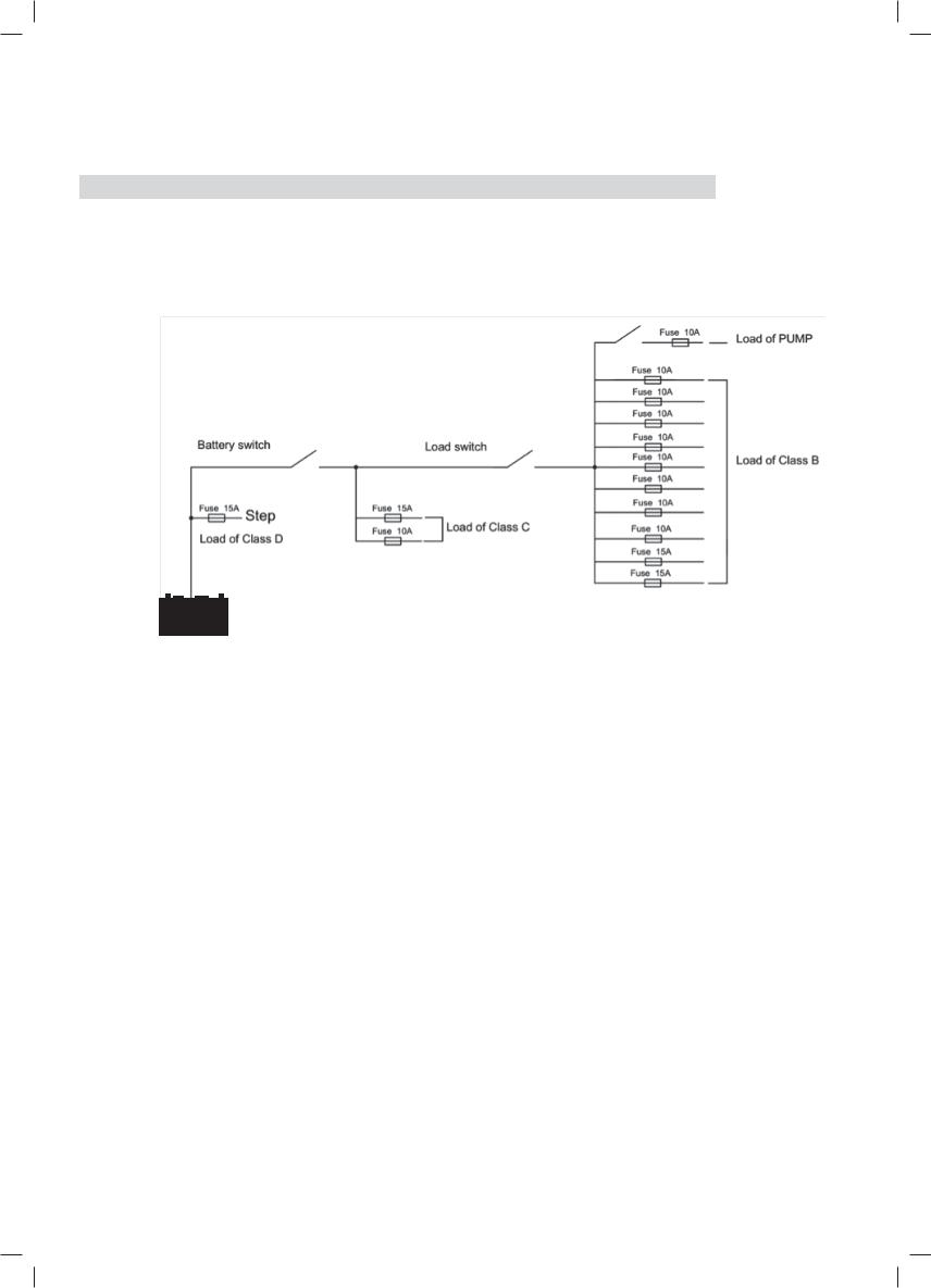
2.7 Categorised Outputs
The 14 outputs are categorised into groups and controls as per below:
TYPE |
QTY |
DESCRIPTION |
POSSIBLE LOAD SUITABLE |
|
|
|
|
Class A1 |
1 |
Relay controlled output with fuse, protected by |
Water pump |
|
|
main master switch relay |
|
Class B |
10 |
Fused outputs, protected by master switch relay |
Ventilation fan etc |
|
|
|
|
Class C |
2 |
Live load |
Fridge, security alarm etc. |
|
|
|
|
Class D |
1 |
Permanent on load |
Auto step |
Table 2 Categorised outputs
Figure 7 Categorised output
2.8 Battery Low Voltage Protection (BLVP or commonly known as an LVD)
PM300 master power unit has a built-in low voltage protection relay. It will disconnect the load once the battery voltage drops below the threshold voltage.The default setting is 10.5VDC.This switch can be manually turned On/Off via the LOAD button on the LCD display.
2.9 Battery Switch
The PM300 unit offers a convenient way to switch off the output of the service battery on-board. It protects the service battery from being drained by electronics on board, completely isolating the battery. PM300 unit also supports a remote manual battery switch. Before using the remote switch, ensure the ‘switch selector’ is set to ‘Remote’.
The switch is only effective when the system has no other energy resource for the load except the battery.
2.10 Precise Battery Measurement
PM300 unit has a battery measurement system controlled by microprocessor. It measures battery voltage, charge/discharge current, remaining AH and display time to go.
Compared to conventional indicating meters, a small current can be measured and read accurately with this device. With this feature, it highlights faults, alarms and installation errors.
ATTENTION: If you have loads connected directly on battery instead of PM300 Power Management System, the measurement will not be accurate.
2.11 Silent Mode
,Q6LOHQW0RGH WKHEDFNOLJKWRIWKHPRQLWRUDQGWKHIDQZLOOEHWXUQHGRIIRUGHFUHDVHGLQVSHHG
8
 Loading...