

Page 1

INSTRUCTIONS FOR USE
Pro-Ject 9cc Evolution
Pro-Ject 10cc Evolution
Pro-Ject 12cc Evolution
Page 2
1 Finger lift
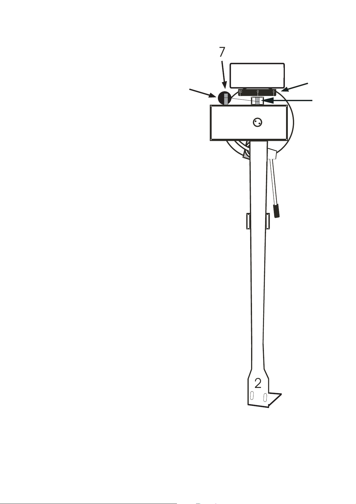
2 Headshell
3 Tonearm tube
4 Tonearm rest
5 Tonearm lift lever
6 Anti-skating weight wire support
7 Anti-skating weight *
8 Tonearm counterweight *
8a Downforce scale
9 Anti-skating weight adjustment scale
10 Tonearm base *
Drilling template for mounting tonearm base *
Tonearm base fixing bolts (3x 12mm M5) *
8
8a
6
9
10
5
4
Wood screws to fix the RCA/phono socket box (2x 2,9 x 9,5)
2x hexagon keys: 1,5mm and 3mm *
3
1
2
© Audio Trade GmbH · Tonarms Pro-Ject 9cc Evo, 10cc Evo and 12cc Evo · Revision 2014.4.1
Page 3

Dear music lover,
thank you for purchasing a PRO-JECT AUDIO tonearm.
In order to achieve maximum performance and reliability with this record player you should study these instructions
for use carefully.
Important notice.
During assembly and adjustment small parts could be lost if not carefully placed in a suitable receptacle.
Before starting assembly make yourself acquainted with the parts listed above and correspondingly numbered
in the technical drawings above. Separately packed items are marked with an asterisk *.
Replacement of a tonearm on Pro-Ject turntables with RCA phono sockets.
Remove the anti-skating (7) and counterbalance weight (8). Remove the screws retaining the socket bracket on
the underside of the plinth. De-solder all wires. After loosening the two hexagon screws in the base (10) the
tonearm may be carefully pulled up and out of the base (10).
Fit the new tonearm as above but in reverse order. Adjust the arm height and azimuth as described on pages 4.
Fitting tonearms from other manufacturers
Lay the enclosed template over the platter spindle. Mark the centers for the mounting hole and the three
screwholes with a sharp tool. Whilst aligning the template please take note that the two hexagon grubscrews
in the base (10) must be aligned at 10 and 2 o’clock. Make sure there is sufficient room to the rear and side
of the arm base (10) for the arm to turn without hindrance when the lid is closed.
After drilling the holes and cleaning up the edges screw the arm base (10) to the mounting surface with the
three bolts. The two hexagon grubscrews in the base (10) should be aligned at 10 and 2 o’clock.
Lead the internal wiring out through the hole in the arm base, then connect it to the output sockets of your
record player, or to the RCA/phono socket box supplied with the tonearm. The socket box must then be
attached to a suitable place on the turntable plinth. Finally, adjust the arm height and azimuth as described
on pages 4.
The Pro-Ject 9cc Evolution tonearms fit all turntables which use the Linn mounting standard.
No soldering is required for tonearms fitted with a standard 5-pole connector socket. Just connect the
tonearm leadout to the 5-pole socket.
Fitting and connecting the cartridge
All cartridges with half inch mounting holes can be fitted. Leaving the needle's protection cover on, fit the
cartridge to the headshell (2) using the screws supplied with the cartridge by passing one screw through each
slot in the headshell (2). Do not tighten the nuts yet. Connect the tonearm wires to the cartridge pins as
follows:
white left channel positive (L+)
red right channel pos. (R+)
green right channel return (R -)
blue left channel return (L -)
The full sound quality of the PRO-JECT tonearms can only be achieved if the cartridge is correctly adjusted.
Particular tools like the PRO-JECT alignment tool are required to accomplish this job properly. If you are not
well acquainted with the adjustment of cartridges you are advised to call upon the willing help of your PROJECT dealer to accomplish this task for you.
Please note: adjusting a cartridge and tonearm calls for the greatest care in order to avoid damaging
the cartridge or tonearm bearings. Leave this work to your dealer if you are in any way unsure of the
necessary steps and precautions to be taken.
© Audio Trade GmbH · Tonarms Pro-Ject 9cc Evo, 10cc Evo and 12cc Evo · Revision 2014.4.1
3
Page 4

Cartridge downforce adjustment
Remove the transport lock (4a) from the tonearm tube (3). Store it in the original packaging so they are
available for any future transportation.
Pushing carefully, turn the counterweight (8) onto the rear end of the tonearm tube (3), so that the downforce
scale (8a) shows towards the front of the player. Lower the armlift and position the cartridge in the space
between arm rest and platter. Carefully rotate the counterweight (8) until the armtube balances out. The arm
should return to the balanced position if it is moved up or down. This adjustment must be done carefully. Do
not forget to remove the cartridge protection cap if fitted.
Once the arm is correctly balanced return it to the rest. Hold the counterweight (8) without moving it, and gently
revolve the downforce scale ring (8a) until the zero is in line with the anti-skating prong (9). Check whether the
arm still balances out.
Rotate the counterweight counter clockwise (seen from the front) to adjust the downforce according to the cartridge
manufacturer's recommendations. One mark on the scale represents 1 mN (= 0,1g / 0,1 Pond) of downforce.
Adjust the downforce prior to installing the anti-skating weight.
For further information on supplied and optional counterweights see the last page.
Adjusting the azimuth
The cartridge needle must be vertical in the record groove in order to trace the
groove wall modulations correctly.
A small screw at the bearing end of the arm tube (3) allows incorrect azimuth
Madenschraube
to be corrected if your needle is not mounted exactly perpendicular to the
cartridge body (which is often the case).
Slacken off the screw just enough to be able to revolve the arm tube (3) without
applying force. Note! Do not remove the screw completely!
With the aid of a good magnifying glass adjust the needle until it is vertical in the groove (i.e. perpendicular
to the record's surface). Ideally this should correspond to the top surface of the cartridge body being parallel
to the record surface, but in practice this is often not the case.
Under no circumstances should the arm tube be adjusted with the needle still in the record groove!
Irreparable damage may be caused to the cantilever suspension! The arm must be lifted to make
each adjustment and lowered afterwards to check it.
Anti-skating force adjustment
The anti-skating force must be adjusted according to the mass of the cartridge as follows:
Pro-Ject 9cc Evolution and Pro-Ject 10cc Evolution
Downforce
10 - 14mN 1
15 - 19mN 2
20mN and bigger
Groove in the stub (9)
st
from bearing rings
nd
" " "
3
rd
" " "
9
Pro-Ject 12cc Evolution
Downforce
8 - 11mN 1
12 - 14mN 2
15mN and bigger
Groove in the stub (9)
st
from bearing rings
nd
" " "
3
rd
" " "
9
Hang the loop of the thread of the anti-skating weight (7) in the groove of the anti-skating stub (9) corresponding
to the downforce applied to your cartridge and hang the thread in the groove of the wire support (6).
Adjusting the vertical tracking
Put a record on the platter. When the needle is lowered into the record groove and the tonearm is not resting
on the lift arm, the arm tube (3) of the tonearm should be parallel to the surface of the record.
If it is not loosen both hexagon screws in the tonearm base (10) just enough to allow vertical movement of
the arm pillar without force and slide the arm up or down until it is parallel.
Carefully retighten both hexagon screws without applying excessive force (which would deform the arm pillar)
– finger tight is quite sufficient.
4
© Audio Trade GmbH · Tonarms Pro-Ject 9cc Evo, 10cc Evo and 12cc Evo · Revision 2014.4.1
Page 5

Service
Should you encounter a problem, please contact your dealer for further advice. Only when the problem
cannot be resolved there should the unit be sent to the responsible distributor in your country.
Never return a tonearm without making sure that is it safely disassembled and correctly packaged in the
original packaging. Guarantee repairs will only be effected if the unit is returned correctly packaged. For this
reason we recommend keeping the original packaging.
Please remove these parts and pack them separately: tonearm base (10), counterweight (8), anti-skating
weight (7) and cartridge.
PRO-JECT is a Registered Trademark of H. Lichtenegger.
This guide was produced by: Audio Trade GmbH
Copyright
©
2008. All rights reserved.
The information was correct at the time of going to
press. The manufacturer reserves the right to make
changes to the technical specification without prior
notice as deemed necessary to uphold the ongoing
process of technical development.
Technical specifications
1”= 2,54cm Pro-Ject 9cc
Evolution
Headshell 0,5” standard:
Mounting distance arm base 212mm 238mm 291,6mm
Armtube made of carbon-fibre carbon-fibre carbon-fibre
Headshell made of carbon-fibre carbon-fibre carbon-fibre
Eff. tonearm length 9“ 10“ 12“
Eff. tonearm mass 8g 8,5g 10,5g
Overhang 18mm 16mm 13,2mm
Supplied counterweights for 5 - 7,5g (no. 28) 4 - 6g (no. 30) 4 - 7g (no. 27)
cartridge weights 7 - 10g (no. 46) 5 - 8g (no. 46) 6 - 9g (no. 31)
counterweight no. ( ) 9 - 11g (no. 43) 6 - 10g (no. 44) 8 - 12g (no. 32)
Optional counterweights
counterweight no. ( )
Downforce range 10 - 35mN 10 - 35mN 10 - 35mN
Weight (without counterweight) 265g 269g 271g
All tonearms are available either with flying leads terminated with a 5-pole standard tonearm
socket, or with a cable terminated with RCA phono sockets.
10 - 14g (no. 29) 8 - 14g (no. 31) 10 - 15g (no. 33)
8 8 8
------- 16 - 22g (no. 33) 16 - 22g (no. 47)
Pro-Ject 10cc
Evolution
Pro-Ject 12cc
Evolution
© Audio Trade GmbH · Tonarms Pro-Ject 9cc Evo, 10cc Evo and 12cc Evo · Revision 2014.4.1
5
 Loading...