

Page 1
INSTRUCTION
MANUAL
VERSION 4
INDEX
Sec.
INDEX / PRESENTATION 1
1. BASIC FUNCTIONAL DESCRIPTION 2
2. INTRODUCTION TO THE MANUAL 3
Sections for the installer
3. DIMENSIONS 3
4. INSTALLATION 4
4.1 Placing the unit 4
4.2 Connection 5
4.3 Guide to malfunctions 7
4.4 Additional information for the installation of options
5. TECHNICAL CHARACTERISTICS 10
6. PARAMETERS 11
6.1 Fertilizer parameters 11
6.2 Filter cleaning parameters 12
6.3 Various parameters 12
6.4 Clock parameters 14
6.5 Additional information for diesel option parameters
PRESENTATION
We wish to take this opportunity to thank you for the confidence in us which you have demonstrated in ex-
pressing interest or acquiring the AGRÓNIC 2000.
This confidence, for our part, stimulates our efforts to meet and surpass the expectations of our clients to jus-
tify the traditional quality of our products.
This manual will explain the specification of the equipment as well as its installation and use.
However, if after reading this you still have any doubts, contact us and we will happily answer them.
Theme Page
8
15
Sections for the user
7. USE 16
7.1 Programs 16
7.2 Manual 19
7.3 Totals 19
7.4 Consultation 20
8. ADDITIONAL INFORMATION FOR
VOLUME
8.1 Parameters 22
8.2 Programs 22
8.3 Totals 22
8.4 Consultation 22
8.5 Anomalies 22
9. ADDITIONAL INFORMATION FOR
DIESEL OPTION
9.1 Consultation 23
9.2 Anomalies 23
9.3 Malfunctions 23
NOTES 24
1
22
23
Page 2

2
1. BASIC FUNCTIONAL DESCRIPTION
This equipment is for the control of the irrigation
system, fertilization, fertilizer mixing, pumps and the
cleaning of the filters, with the detection of malfunctions and visualization of data.
There are models with 6, 12, 18, and 26 independent outlets plus 5 signal inputs.
Programmable for time or volume.
IRRIGATION
The system has a capacity for 31 independent or
sequential programs.
Programming can be for daily or weekly action or
with several activations every certain period of time on
the program number 1.
Up to 8 sectors can be operated simultaneously.
Grouping sectors together to simplify programming.
Also manual activation and deactivation of programs, outlets and filters.
Irrigation program starting by input connected to
an external sensor, being able to do an irrigation sequence to be disconnected in manual mode.
FERTILIZATION
The equipment can be configured from 0 to 4 fertilizers, in separate tanks, with the following configuration possibilities:
- post-irrigation minutes.
- separation minutes between fertilizers.
- fertilizers pump, when there are more than one fer-
tilizer tanks.
- mixers for each fertilizer tanks.
- pre-mixing minutes.
- continuous, intermittent or stopped mixing while it
fertilizers.
The value of application of each fertilizer can be
programmed independently for each program.
The fertilizers can be applied in “series” one after
the other with only one injector, and if it is working by
volume only one counter.
Also can be applied in “parallel”, several fertilizers at once, with one injector for everyone, and always
by time.
PUMPING
The system can govern an electro-pump or a
general valve. To avoid problems of the water hammer
in the pump, special temporization sequences are
provided between the opening of the sector valves
and the starting of the pump, and also between its
stopping and the closing of the valves. The same applies to the changes of sector.
In diesel engine (optional) the unit realize a complete control, with several start attempts, pre-heating,
automatic stop, malfunction detection, etc.
CLEANING OF FILTERS
This can be configured from 0 to 9 filters, with
variable washing time. Pause time between filters.
The washing sequence can be started by the
pressure difference and/or the time or volume of water
circulation.
Irrigation sectors can be stopped while filters are
being cleaned.
While the cleaning is carried out, the fertilization
is stopped.
ALARMS
By means of corresponding sensors, the equipment detects malfunctions and acts accordingly, on
the basis of pre-established parameters, meanwhile
leaving a visual record (the input signal may be delayed).
The clock can be set to stop or not, in case of
failure of the electricity supply.
There are five input signals, which can be configured for the following functions: irrigation volumetric
counter, fertilizer volumetric counter, differential pressure gauge of filter cleaning, temporary malfunction,
general malfunction, conditional stop and program
starting.
VISUALIZATION
Complete visualization in 40 character alphanumeric LCD screen and a 14 function key waterproof
keyboard. All information concerning one program is
displayed on the screen.
You can consult, correct and erase by programs.
While a program is being executed, all information
concerning it is being displayed.
It controls and registers electricity supply cuts,
simultaneous working of more than eight sectors, the
overlap of two or more programs with fertilizer, external malfunctions with general or temporary stop, etc.
There are coun te rs for the totals of the units of water and fertilizer application for each sector, as well as
another general counter for water and fertilizers.
MODELS AND VERSIONS
- Models for 6, 12 , 18 and 26 outlets.
- Version with power 220 Vac and outlets 24 Vac.
- Version with power 115 Vac and outlets 24 Vac.
- Version with power 12 Vdc and outlets 12 Vdc.
- Option for power at 12 Vdc , 220 Vac and 115 Vac
and outlets at 12 Vdc and 24 Vac, respectively, for
generating sets.
- Equipment version provided in a box
parent front cover.
- Equipment version prepared to building-in
board or desk.
- Option of automatic start of engine or diesel generating set.
- Option for two independent pumps.
with trans-
a cup-
Page 3

3
- Option with outlets for latch valves (pulses) and
minimum electric consumption. Due to its low electric consumption of the equipment and its electrovalves, this version is very suitable for installations
which work with a battery and which have not got
diesel engines or solar panels.
- Optional distance management via SMS messages, with modem GSM/GPRS included. Also, optional links to a PC or an irrigation network program.
WARRANTY
The AGRÓNIC 2000 irrigation controller meets all
the norms set by the EC.
The products created by PROGRÉS enjoy a two-
year warranty against all manufacturing defects.
Compensation for direct or indirect damage
caused by the use of the equipment is excluded from
the warranty.
2. INTRODUCTION TO THE MANUAL
is a complete irrigation system whose
capacity an specifications the user and installer
should know in order to get the most out of it. For this,
we recommend a detailed reading of this manual.
The most important chapters are:
The INTRODUCTION is where you are at this
moment and we recommend a thorough reading both
for installers and users.
The INSTALLATION is the chapter directed at the
installer who has to connect the equipment to the
other elements, which comprise the automatic irrigation system.
PARAMETERS is the chapter which explains how
to configure and set up the system for the particular
needs of each installation. This is work for the installer
but it is also interesting for the user in case any parameters have to be modified after the installation of
the equipment.
The USE is the chapter aimed basically at the
user where all the instructions for programming
found.
Start reading the chapter which best suits you,
according to your condition of installer or user.
Before installing the unit, it should be checked to
see that it corresponds with your requirements.
This can be done by checking that the identification labels correspond with the desired model.
To decide on the necessary model (number of
outlets), the irrigation sectors needed, the number of
fertilizers, mixers, fertilizer pump and filters which are
to be used, have to be added up.
2 Introduction
4 Installation
6 Parameters
7 Use
will be
Examples:
- If we have 2 irrigation sectors, 1 fertilizer and 2
filters, the model 2006 is sufficient (2+1+2
=5).
- If we have 3 sectors, 2 fertilizers, 1 mixers and
2 filters, the model 2012 is needed (3+2+1+2
=8).
The equipment has an alphanumeric screen with
40 characters, which shows: the questions that the
controller asks the user, his answers, the stored parameters and programs, the current performances, the
applied water and fertilizer quantities, the malfunctions
and incidents, etc.
It has also got a keyboard with 14 keys, which is
used to access the equipment, to configure, program,
correct, consult, erase, activate, deactivate, etc.
The keys from 0 to 9 should be pressed whenever it is necessary to enter a number.
The same keys also show the initials of the days
of the week and they will be used whenever it is necessary to enter one day in the controller.
There are two keys with the words "YES" and
"NO" which will be pressed, in a few cases, when one
option or other has to be chosen (and when indicated
on the screen) .
There is also a key with an arrow which is used
for moving fast through the sector numbers and programs as will be explained later.
The "ENTER" key is used to confirm the validity of
the data previously entered and shown on the screen
with the cursor below it or displayed intermittently on
the screen. This key is bigger as it is used constantly.
The "VIEW" key is used to consult anomalies
stored in the controllers memory, the current state of
the inputs/outlets, etc.
The "FUN" key is used for entering into the four
basic functions of the controller: PROGRAMS (automatic control by means of the programs entered),
MANUAL (control by manual orders to be carried out
immediately), PARAMETERS (configuration of the
equipment to the particular needs of the installation)
and TOTALS (access to the internal counters for the
time and volume of the water and the fertilizer applied).
Page 4
4
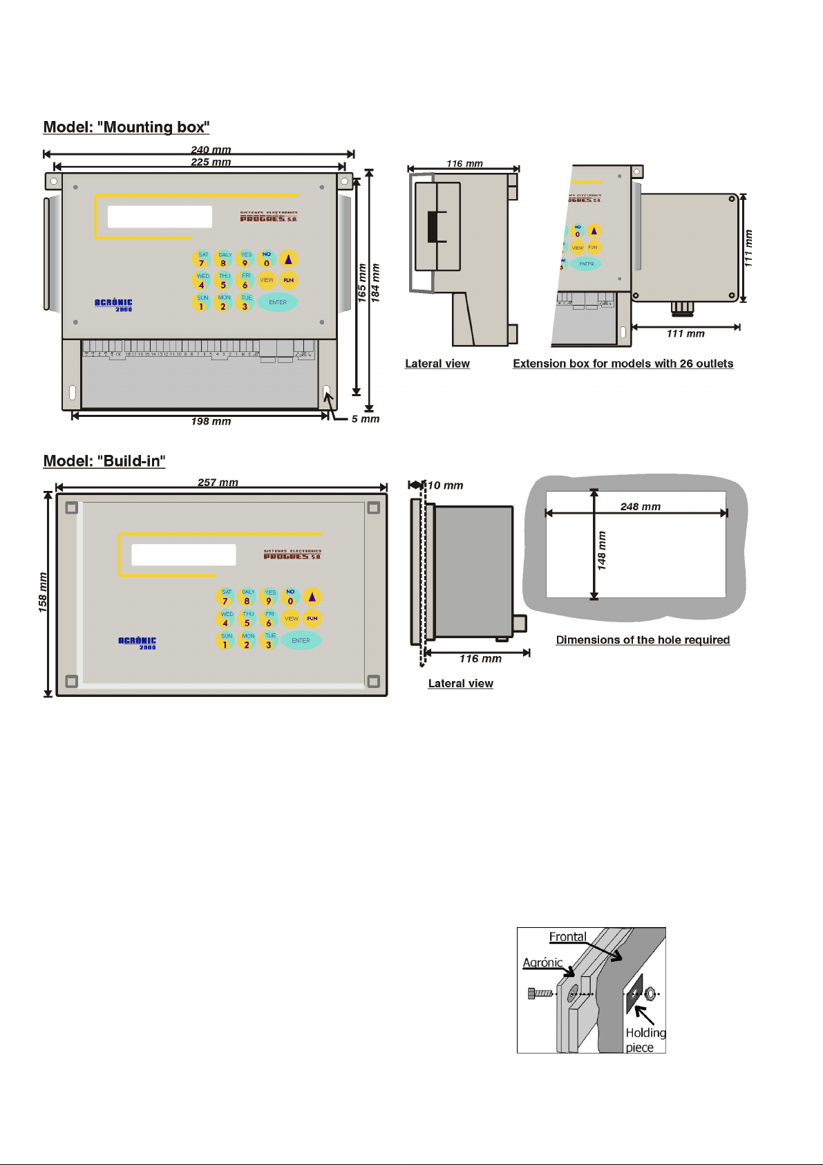
3. DIMENSIONS
4. INSTALLATION
4.1. PLACING THE UNIT
Place the unit at the right position and height.
Avoid direct sun exposure, humidity, dust and vibrations.
Avoid proximity to any source of interference
which could affect the correct working of the unit.
In the version with "box", the equipment is provided in a hermetically sealed box (IP65) with a transparent front cover for the keyboard/display and an
opaque cover for the connection housing. In the
model with 26 outlets, a second additional box is provided.
To maintain the isolation of the unit, it is essential
to keep the panels closed, as well as to install cable
glands at the cable outlets, which are provided with
the equipment.
For the wall-mounting of the unit, there are two
holed pieces in the upper corners.
There are also two more holes in the inside of the
connection housing.
In the “built-in” model, a hole is to be done in the
frontal part of the wall or desk, according to the measures in the section DIMENSIONS. It will be held with
the screws at the corners, using the four pieces provided with the unit.
Page 5

5
4.2. CONNECTION
The unit has to be installed following the prevail-
ing regulations for electrical installations.
In the “box” model, the cable glands provided
with the unit are to be installed, removing the relevant
dies (this should be done with the connection cover in
place and screwed to avoid possible breakage).
In the “built-in” model the terminals are placed at
the back and they are the
connector type. On placing
the terminals check that they
have been introduced in the
guides, as it is shown in the
figure.
It is advisable to connect the cables to the terminals with terminal connections, which are also included with the unit.
There is also a protection box for all the terminals, in case there is a risk of electrical sparks from
storms entering the cables.
4.2.1. Supply to the equipment
Before connecting the unit, it is necessary to
check its identification label where the characteristics
of the power supply are to be found.
• Power supply at 220 Vac or for model at 115 Vac:
A 6 amp magnetothermic switch is to be included
in the installation. It will be used as a disconnection
device and it has to be placed near the unit and at an
accessible place for the user.
It is recommendable to do this as directly as pos-
sible, avoiding that the same cable supplies other
sections. Use cable of the H05VV-F type, 1mm
A fuse (general fuse) and a varistor protect the
mains input. The varistor might short-circuit the fuse
automatically, on detecting an overload on the line
(lightning, etc.); replace it with one of the same characteristics.
For unstable or fluctuating voltages use grid stabi-
lizers.
If the unit is to be disconnected from the power
line during several weeks, it is advisable to remove
the bridge marked as “J4” (next to the battery) in the
circuit placed behind the keyboard, and insert it
again before connecting it to the power line.
• Power supply at 12 Vdc:
Check the polarity of the terminals.
Connect two direct cables from the battery to the
equipment power (±12) avoiding that those cables
supply other units or elements.
If the battery is far away from the controller, use
high section cables and make a reduction when entering the equipment.
The input is also protected with a fuse and a varis-
tor.
Avoid, if there is a diesel engine working, that this
one works without the battery, as the alternator
2
.
would increase the equipment power tension momentarily.
To replace the fuse, h alf tur n th e fu se c ove r an d
insert another of the same value.
4.2.2. Connecting the earth terminal
The “built-in” model has a terminal screw to connect the protection earth terminal, and which is placed
near the power terminals.
In the “box” model, a protection terminal is not
needed, but it has got a box terminal marked as:
to be connected to the earth terminal.
Both the earth and box terminals are used to protect the unit by directing all electrical sparks produced
by the internal gas discharger to the earth. These
sparks can come in through the outlet cables.
CP
4.2.3. Connecting inputs
The contacts that join the inputs with the input
common, have to be normally open and free of voltage.
The inputs are optically insulated from the internal circuitry, except in the version with power supply
at 12 Vdc and latch outlets.
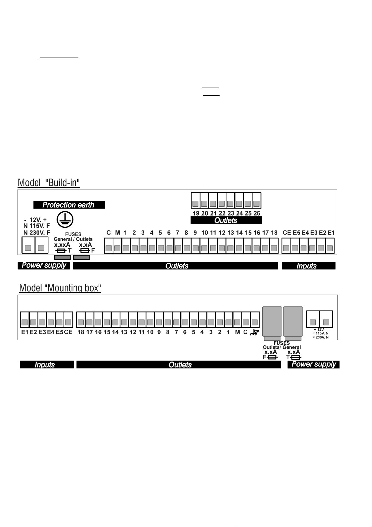
There are five inputs marked as E1 E2 E3 E4 E5,
plus the input common marked as CE.
Every input can be configured for one of the following functions:
• IC Irrigation counter
to this input the volumetric counter with pulse input of the irrigation water.
• FC Fertilizer counter
the fertilizer counter to this input.
• SC Start cleaning
ferential pressure gauge to start the cleaning of
the filters; joining the input to the input common
(CE), and after a fixed temporization of 30 seconds, the cleaning is started, if there is any irrigation program working.
• TM Temporary malfunction
put with the common CE activates the temporary
malfunction (“temporary malfunction” is that
which produces a stopping of the irrigation program being carried out and which reactivates the
system with the beginning of the next program).
There is a programmable delay for the detection
of this malfunction.
• GM General malfunction
the common CE, it activates the general malfunction (“general malfunction” is that which produces
the complete stopping of the system until it is reactivated manually by the user). There is a programmable delay for the detection of this malfunction.
• CS Conditional stop
the common will interrupt the program being carried out. On taking away the union of the input
the common, working is restarted at the
with
. Working by volume, connect
. Working by volume, connect
. If there is any, connect the dif-
. The union of this in-
. Joining this terminal with
. The union of this input with
Page 6
6
same units where it stopped. There is a programmable delay for this detection.
• PS Program start
external order when this input is joined to the
common, the programmed delay has gone by and
the clock has changed minute. The input can not
start again until the program or its sequence of
programs has finished.
. A program will be activated by
4.2.4. Connecting outlets
Connect the solenoids, relays, etc. between the
common of outlets “C” and the corresponding outlet.
Do not surpass the charge per outlet and com-
mon. In case of more intensity, insert external re-lays.
The “outlet fuse” protects from overloads and
short-circuits. To change it, just half turn the cover of
the fuse holder, take it out and replace it with a similar
one.
The outlets are isolated from the interior circuitry
by relays and protected by a varistor in each one.
• C Outlet
• M Outlet
and it is activated whenever an irrigation program
is being carried out.
• Outlets 1 to 6, 12, 18, 26, according to model.
Everyone of them corresponds to an irrigation
sector or a general outlet such as fertilizers, mixers, fertilizer pump and filters, which are automatically assigned to an outlet number in the ”FUNCTION” - “PARAMETERS” - “VARIOUS” section.
. Outlet common.
. It belongs to the pump or general valve,
Page 7
7
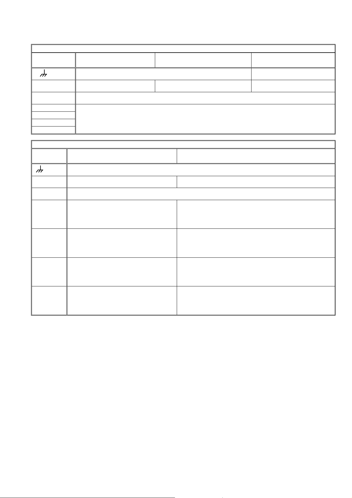
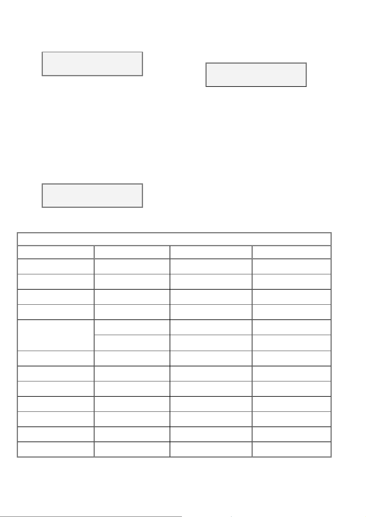
Outlet assignation tables according to unit models.
Model
Outlets Input 230 V or 115 V, Out-
CP
lets 24 V
Box terminal, connected to earth (Built-in model) Stop common
Input 12 V, Outlets 12 V Input 12 V, Outlets 12 V
Latch Option 3 cables
C Outlet common 24 V. Outlet common 12 V. Start common
M Pump/General valve
1-6
1-12
1-18
Irrigation sectors and general outlets, according to configuration.
1-26
Model
Outlets Input 12 V, Outlets 12 V.
CP
Diesel version
Box terminal, connected to earth (Built-in model)
Input 12V/230V or 115V, Outlets 12V/24V.
Diesel version with double tension
C Outlet common 12 V Outlet common 24 V
M Engine starter, position 15/54 of the engine key (12 V)
1-6
6 = Start, 5 = Stop
(Pre-heating / Electro-pump)*
Rest = Sectors and general outlets
6 = Start (12 V), 5 = Stop (12 V)
( Pre-heating** (12V) / Electro-pump (24V) )
Rest = Sectors and general outlets (24 V)
1-12
1-18
1-26
12 = Start, 11 = Stop
(Pre-heating / Electro-pump)*
Rest = Sectors and general outlets
18 = Start, 17 = Stop
(Pre-heating / Electro-pump)*
Rest = Sectors and general outlets
26 = Start, 25 = Stop
(Pre-heating / Electro-pump)*
Rest = Sectors and general outlets
12 = Start (12 V), 11 = Stop (12 V)
( Pre-heating** (12V) / Electro-pump (24V) )
Rest = Sectors and general outlets (24 V)
18 = Start (12 V), 17 = Stop (12 V)
( Pre-heating** (12V) / Electro-pump (24V) )
Rest = Sectors and general outlets (24 V)
26 = Start (12 V), 25 = Stop (12 V)
( Pre-heating** (12V) / Electro-pump (24V) )
Rest = Sectors and general outlets (24 V)
* When any outlet it is used for pre-heating and/or electro-pump, the outlet number occupied will be the afterward
of start and stop outlet of the determined model.
** The pre-heating outlet for equipment with dual voltage option is not standard and must be indicated by
the installer when the equipment is purchased.
4.3. GUIDE TO MALFUNCTIONS
- Valves do not work:
Check the state of the fuses.
Check if any cable is disconnected or cut.
- The equipment does not work properly:
a) There is a black stripe on the screen:
o Disconnect the power supply of the
unit.
o Remove the “J4” bridge (battery bridge)
for one minute.
o Connect the power supply.
o Replace the “J4” bridge.
b) The screen is completely blank:
Check if the power reaches the equipment.
Check the state of the fuses.
- The unit fuses the general fuse constantly:
The protector of overloads is short-circuited, it is
necessary to replace it. This happens when the
unit is supplied at 380V, for example, or there is
an overload due to a storm and the “general
fuse” is superior to the one indicated in the section about technical characteristics.
o Finally assemble the equipment.
Page 8
8
4.4. ADDITIONAL INFORMATION FOR THE INSTALLATION OF OPTIONS
4.4.1. Diesel version
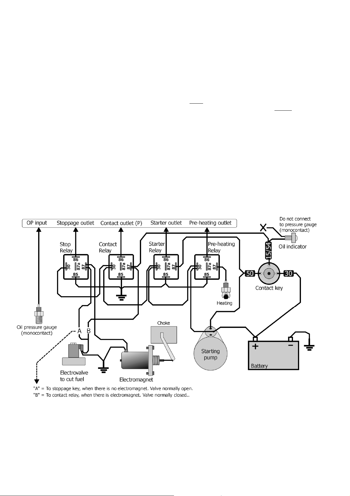
When connecting the version with diesel starting
engines, we have to take into account the following
details:
A. INPUTS
OP oil pressure gauge. In the diesel starter version, the function of input of pressure gauge is automatically connected to input 5. There is a delay of 10
seconds in the detection. The pressure gauge can
only be connected to this input.
B. OUTLETS
The M outlet corresponds to the order of contact
of diesel engine; it will be connected with the cable of
the terminal “15/54” of the key. The unit starts and
stops the contact, so the key has to be left at rest position.
A supplementary relay will be placed at the
starter outlet, and it must have a capacity of 20 to 30
amps. Its outlet has to be connected to the terminal
cable “50” of the key.
If the engine stops by electromagnet, a supplementary relay will be installed between the former one
and the stop outlet.
If the stop is done by cutting the oil supply with
an electrovalve, this electrovalve should be installed
as close as possible to the injector, so that the stop is
as quick as possible. When the electrovalve is normally open
directly. If the electrovalve is normally closed
be connected to the contact outlet (M).
tercalated for its working.
C. GUIDE TO MALFUNCTIONS “DIESEL VERSION”
- All the attempts are made, even when the unit
- The battery runs down:
, it has to be connected to the stop outlet
, it has to
In case of pre-heating, an outlet relay will be in-
has been started at the first try:
The oil pressure gauge does not work properly,
it continuously connected to the common or
box.
The contact signal is not given to the engine, or
the battery is faulty.
Page 9
4.4.2. Latch option
The low consume of the equipment (0.12
watts/hour), and its latch electrovalves, make this option suitable for those installations which work with
battery. It is not indispensable, but a small solar panel
can be mounted to avoid the normal manual loading
of the battery.
To reduce consumption, the controller has a system which switches the screen off when the keyboard
is not in use. To activate the display, simply press any
key on the Agrónic.
A. LATCH ELECTROVALVES WITH TWO CABLES
This electrovalve model works reversing the polarity between the two cables, to activate or deactivate
it.
One of the cables is to be connected to the outlet
common “C” and the other one to the corresponding
outlet.
If the electrovalve does the opposite of what the
controller has ordered it to do, it would be necessary
to reverse the cables that are connected to the common and outlet.
B. LATCH ELECTROVALVES WITH THREE CABLES
This models have a bridge in the right superior
part of the base card to change the working voltages
to the outlets (see indicative stick). Without the bridge
the outlets are working to 12 Vdc and with the bridge
installed they will have a voltage near to 24 volts.
From the company the units are delivered with the
bridge connected. The voltage depends on the type of
solenoids, by this, it can be changed depending on
your needs.
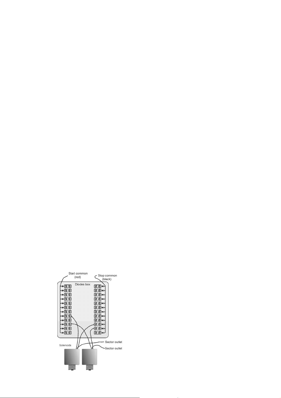
Also it is included for this version a diode box, to
which two of the three cables, the red and the black
one, belonging to each solenoid have to be connected. The red one will be connected to the group of
terminals linked to the red cable which goes to the
controller (start common). The black one will be connected to the other group of terminals (stop common).
The order of the sector numbers is not taken into
account in the terminals of the diode box.
Example of connection:
9
The other cable, normally white, will be connected to the controller, to the outlet corresponding to
its sector or to the “M” general valve outlet.
4.4.3. Two pump option
In this option the second pump or general valve
2 will be connected to the last outlet of the controller.
A group of correlative sectors is assigned to
every pump, pump 1 is for the group of the first sectors and pump 2 for the rest.
This assignation will be done in the configuration
of the installer.
4.4.4. Installer configuration
To go to installer configuration, follow the next
instructions: In function 3, ”Parameters”, pressing
“ENTER”, and pressing “9” and “ENTER”, then it is
needed to enter an access code.
Continuously, it will ask several question that it
only must be entered when it will necessary in order to
not erase any data or cause any malfunction in the
unit or in the installation. Pressing only the key “ENTER” it will go through the question without doing
anything.
The question are asked like this:
- “Ram to 0”, answer with “YES” to erase all the pro-
grams information in course, anomalies and totals.
- “Eeprom to 0”, to erase all programs and parame-
ters.
- “M1 Sectors”: we will indicate the number of sec-
tors that will activate engine 1, the number entered
here will correspond to section 1, the rest are excluded or activate engine 2 in the case of the 2 engine option.
- “Sector limit”: by default a maximum of 8 sectors
are allowed to act simultaneously, enter the appropriate value to reduce this.
- “Fertilization, 1: series 0:parallel” entering a 1 it will
do series with one fertilizer after the other, with 0,
several at once.
- “Fertilizers stop” To stop or not the fertilization
while the cleaning filter is carried out.
- “Conditional stop is System stop”, when the condi-
tional stop will take place it will work like a system
stop (Function-Manual), with this function it keeps
discounting the irrigation program time, but without
deactivate the outlets.
- “Frequency h:mm”, answer “YES” if you want the
activation frequency in hours and minutes; if you
answer “NO”, the frequency will be in hours.
Pressing “ENTER” again, it goes back to view, in
the main screen.
Page 10
10
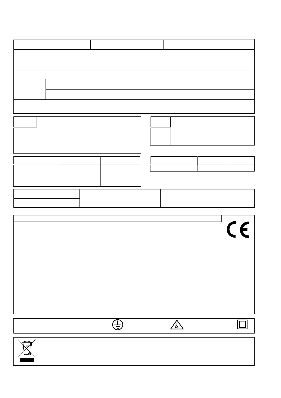
5. TECHNICAL CHARACTERISTICS
Power supply Units for alternating current Units for direct current
Voltage
230 Vac or 115 Vac
+5%-10% CAT II
Frequency 50-60 Hz ---------Energy consume Below to 58 VA (at rest 2.7 VA) Below to 7 W (at rest 0.6 W)
Fuses
Input 0,630 A, T type, 250 V (slow) 0,8 A, T type, 250 V (slow)
Outlet 2 A, F type, 250 V (fast) 3,15 A, F Type, 250 V (fast)
12 Vdc +10% -5%
Keeping the memory which can be
Battery, more than 72 hours Condenser, 24 hours
erased when there is a power cut
Outlets
Number 6, 12, 18, 26+1 (according to model)
Type By relay contact, with potential of 24
Vac (Internal transformer) or 12 Vdc
Inputs
Number 5
Type Optocoupled, to connect
to contacts free of
potential
Limits 40Vac/30Vdc, 1 Amp
Atmosphere Temperature 0ºC to 45ºC Weight (approximate) Unit in box 2,2 Kg
Humidity <85% Unit to built-in 2,7 Kg
Height 2000m
Pollution Grade II
Memory backup
Clock, consults Battery or condenser
Program, parameters Non erasable
DECLARATION OF CONFORMITY
It follows the 89/336/CEE Guidelines for the Electromagnetic Compatibility and the 73/23/CEE
Guidelines of Low Tension for the Fulfillment of the Product Security. The fulfillment of the
following specifications was demonstrated as indicated in the Official Diary of the European
Communities:
Emissions EN 50081-1:94 EN 55022:1995 Type B Radiated and conducted emissions.
Immunity EN 50082-1:94 EN 61000-4-2 (95) Immunity to electrostatic discharges.
EN 61000-4-3 (96) Immunity to the electromagnetic field of radioelectric
frequency.
EN 61000-4-4 (95) Immunity to fast transitional in common way.
EN 61000-4-5 Immunity to overloads in the power supply.
EN 61000-4-11 Immunity to lacks and power cuts.
Harmonics EN 61000-3-2 (95) Current harmonics.
Fluctuations EN 61000-3-3 (95) Tension fluctuations.
Low tension guidelines EN 61010-1 Security requirements of measurement electric units,
control and use in laboratory.
Symbols which may
appear in the product
Protection earth
terminal
Danger, risk of
electroshock
Double insulation
This symbol indicates that the electrical and electronic equipment should not be disposed of as
general household waste at its end-of-life. Instead, the product should be handed over to the
applicable collection point for the recycling of electrical and electronic equipment for proper
treatment, recovery and recycling in accordance with your national legislation
Page 11

11
6. PARAMETERS
To do any work with the controller, except “view”,
press the FUN key (Functions) and the following
screen, with the first two options, is displayed:
FUN:”1”= PROGRAMS
FUN:”2”= MANUAL
The PROGRAMS function is used to enter, erase
or read the automatic working orders.
The MANUAL function is used to activate or deactivate at the moment, manually.
When pressing the FUN key again, the following
screen with the other two options is displayed:
FUN:”3” = PARAMETERS
FUN:”4” = TOTALS
The PARAMETERS function is used to adapt the
unit to the specific needs of every installation.
The TOTALS function is used to consult the total
working units in general and sector by sector.
As we have already said, PARAMETERS are the
data which customizes the irrigation controller to the
particular needs of the installation it is destined for.
This data will be fed in by the installer of the irrigation system on mounting the equipment, and they
will be fixed in the memory.
Resume of the parameters which can be configured in the “by time” version.
FERTILIZERS:
• Number of fertilizers (0 to 4).
• Post-irrigation minutes (0 to 99).
• Separation minutes between fertilizers (0 to 99) in
serial fertilization.
• Fertilizer pump (yes or no).
• Mixer to fertilizer 1, 2, 3,or 4 (yes or no).
• Pre-mixing minutes (0 to 99).
• Mixing minutes start/stop (99/99).
CLEANING:
• Number of filters (0 to 9).
• Working time per filter ( 3 to 999 seconds).
• Pause between filters (0 to 99 seconds).
• Time between cleaning cycles (0 to 9999 min-
utes).
• Stop of sectors when cleaning filters (yes or no).
VARIOUS:
• By volume (yes or no).
• Irrigation pulse value (0 to 10000 liters).
• Fertilizer pulse value (0 to 1000 cl).
• Assignation of functions to the inputs.
• Delay for temporary malfunction TM (0 to 999”).
• Delay for general malfunction GM (0 to 999”).
• Delay for conditional stop CP (0 to 999”).
• Delay for program start PS (0 to 999”).
• Delay/ advance between outlets (0 to 250”).
• Automatic assignation of general outlets.
• Assigning sectors to groups.
CLOCK:
• Setting the clock (day, hour, minute).
• Start/stop clock, when the unit is disconnected.
The following notes show how to fix the different
parameters and enter them.
To enter into PARAMETERS, press the FUN key,
the number 3 key and the ENTER key.
The following screen, showing the Parameters
menu, is displayed.
Fertil.:1 Clean.:2
Various:3 Clock:4
Option n.1 refers to the FERTILIZATION parameters; option n.2 refers to the FILTER CLEANING parameters; option n.3 to the VARIOUS parameters and
n.4 to the setting of the CLOCK.
6.1. FERTILIZER PARAMETERS
If option n.1 is chosen (Fertilizer parameters), we
are asked, in the following screen, the number of fertilizers to be used.
Number of
fertilizers, 0 to 4 = 2
If there are fertilizers choose, this screen appears
asking how many minutes of post-irrigation are
wanted, between 0 and 99 minutes.
(Post-irrigation is the time without fertilizer before
the end of the irrigation for the cleaning of the pipe
lines).
Minutes of
post-irrigation = 05
If more than one fertilizer has been chosen, it will
ask for the minutes of separation between the end of
one fertilizer and the beginning of the other (only in
series fertilization).
Minutes of
separation = 02
Page 12
12
If there are several fertilizers, the unit allows a
pump outlet of fertilizer, which is connected whenever
one of them is connected (for various tanks connected
to the same injector).
Fert. Pump (Y/N) = Y
An mixer outlet can be assigned to every one of
the possible fertilizers.
Mixer 1= No
Mixer 2= Y
The "pre-mixing" is the time the corresponding
fertilizer tank will be mixed, before it is injected.
For the pre-mixing time to take place, the preirrigation and the fertilizer separation have to be higher
or equal to the pre-mixing minutes.
Minutes of
pre-mixing = 02
Pause
between filters= 07”
The following question refers to the irrigation time
between two cleaning cycles, going from 0 to 9999
minutes. Setting the value at 0000, the “by time”
cleaning will not work.
Apart from this, the unit will carry out the cleanings ordered by external input or manual control, in
which case, the counter will return to 0, and the temporization will start again.
Irri. minutes between
cleaning cycles = 0120
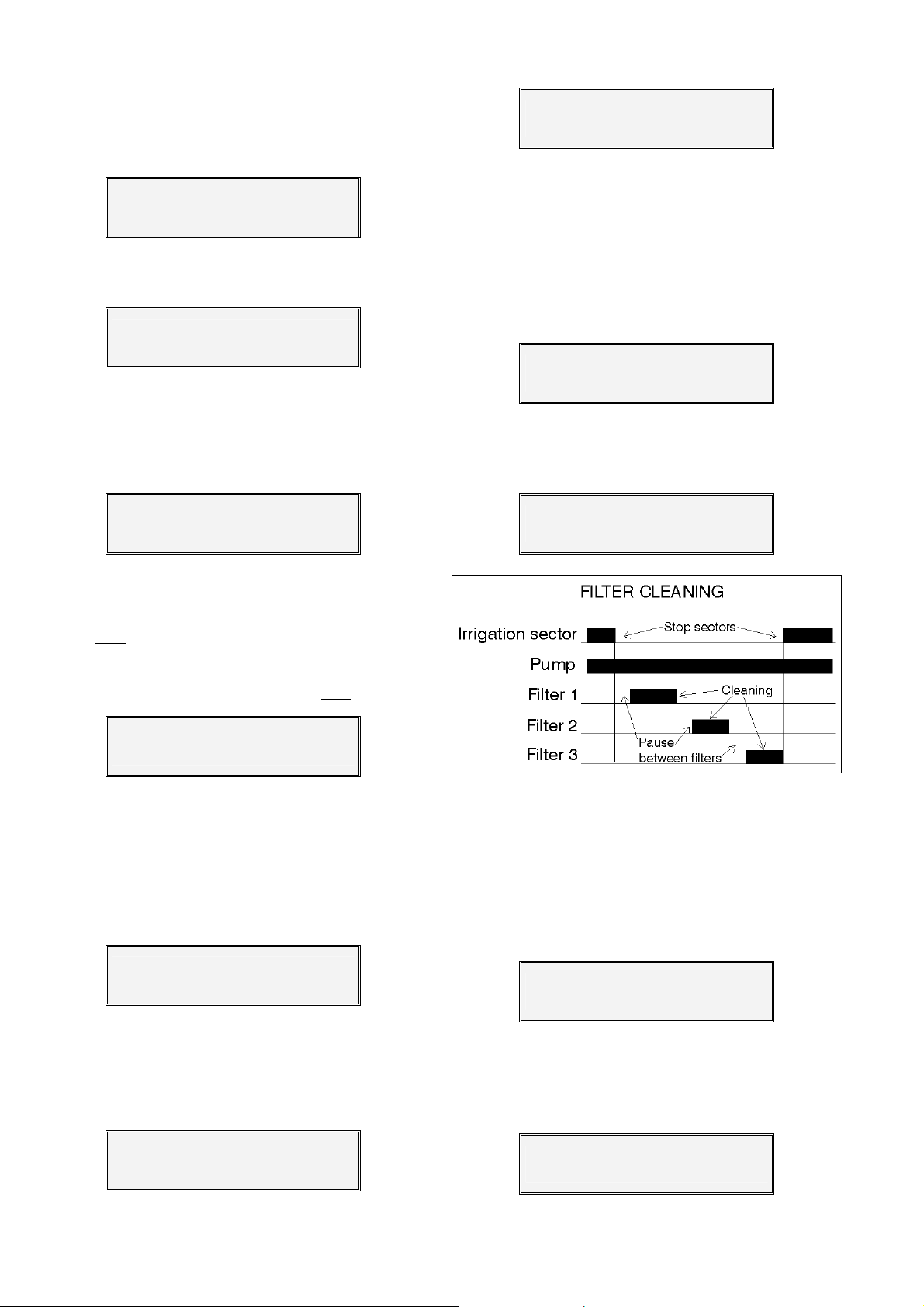
The following screen will ask if the irrigation sectors should be stopped while the filter cleaning is carried out.
Stop sectors = No
The mixing can be continuous, intermittent or
stop (at "stop", only the pre-mixing is carried out).
If it has to work continuously, only enter the minutes at start
value will be entered for the working
; if it has to work intermittently, the desired
and stop minutes; and for it to remain at rest after the pre-mixing,
the desired value will be entered for the stop
minutes.
Mixing minutes
on/off = 02/10
6.2. FILTER CLEANING PARAMETERS
To enter the parameters corresponding to the Filter Cleaning, option n.2 must be selected in the Parameters menu. First, it will ask the number of filters to
be used (between 0 and 9).
Number of
filters = 3
If the previous screen shows that there are filters,
the following question corresponds to the working
time for everyone of them (3 to 999 seconds) and the
pause between them (from 0 to 99 seconds), the
pause is also applied when the first filter starts.
6.3. VARIOUS PARAMETERS
In the section VARIOUS of the Parameters menu,
we are asked whether the irrigation and fertilization
units will be by volume. By volume, the units will be in
cubic meters (m
fertilizers. By time, the unit is hours/minutes (hh:mm).
If the unit works by volume, we have to program
the value of every pulse of the volumetric counter. For
example, if the counter emits a pulse every m
has to be entered.
3
) for the irrigation and liters (L) for the
By volume (Y/N) = Y
3
, 1000
Working time per
filter = 067”
Irrigation pulse
value = 01000 L.
Page 13
13
For the fertilizer counter, the pulse value is in
centiliters. For example, if the counter emits a pulse
every liter, the value will be 100 CL.
Fertilizer pulse
value = 0100 cl.
The following screen is used to assign a function
to everyone of the five inputs. The functions are as
follows:
• IC Irrigation counter.
• FC Fertilizer counter
• SC Start Cleaning
.
: to connect a differential pressure gauge and start the filter cleaning; it will be
done after the set temporization of 30 seconds has
gone by and if any irrigation program is being carried out.
• TM Temporary malfunction:
it produces the stop of
the program being carried out, but reactivates the
system with the beginning of the next irrigation.
• GM General malfunction:
it produces a total stop of
the system until the user manually reactivates it.
• CS Conditional stop:
while the order is carried out
the program carried out is stopped, and on disappearing the order at the input of conditional stop, it
continues at the same place where the irrigation
was stopped. While being at conditional stop, it allows the starting by temporization.
• PS Program start:
It will activate an irrigation program by external order when the programmable
delay has gone by and the clock has changed
minute. The input will not start again until the program or its sequences of programs have finished.
IC FC SC TM GM CS PS
1 2 0 5 0 3 4
The following screens correspond to the detection delay temporizations of some of the input functions, asking how long an input signal has to last for
the unit to consider it valid and act consequently.
TM Input Detection
Delay = 025”
-------------------------------GM Input Detection
Delay = 150”
-------------------------------CS Input Detection
Delay = 008”
-------------------------------PS Input Detection
Delay = 300”
While a filter cleaning is being carried out, the
temporary malfunction or general malfunction inputs
are not taken into account.
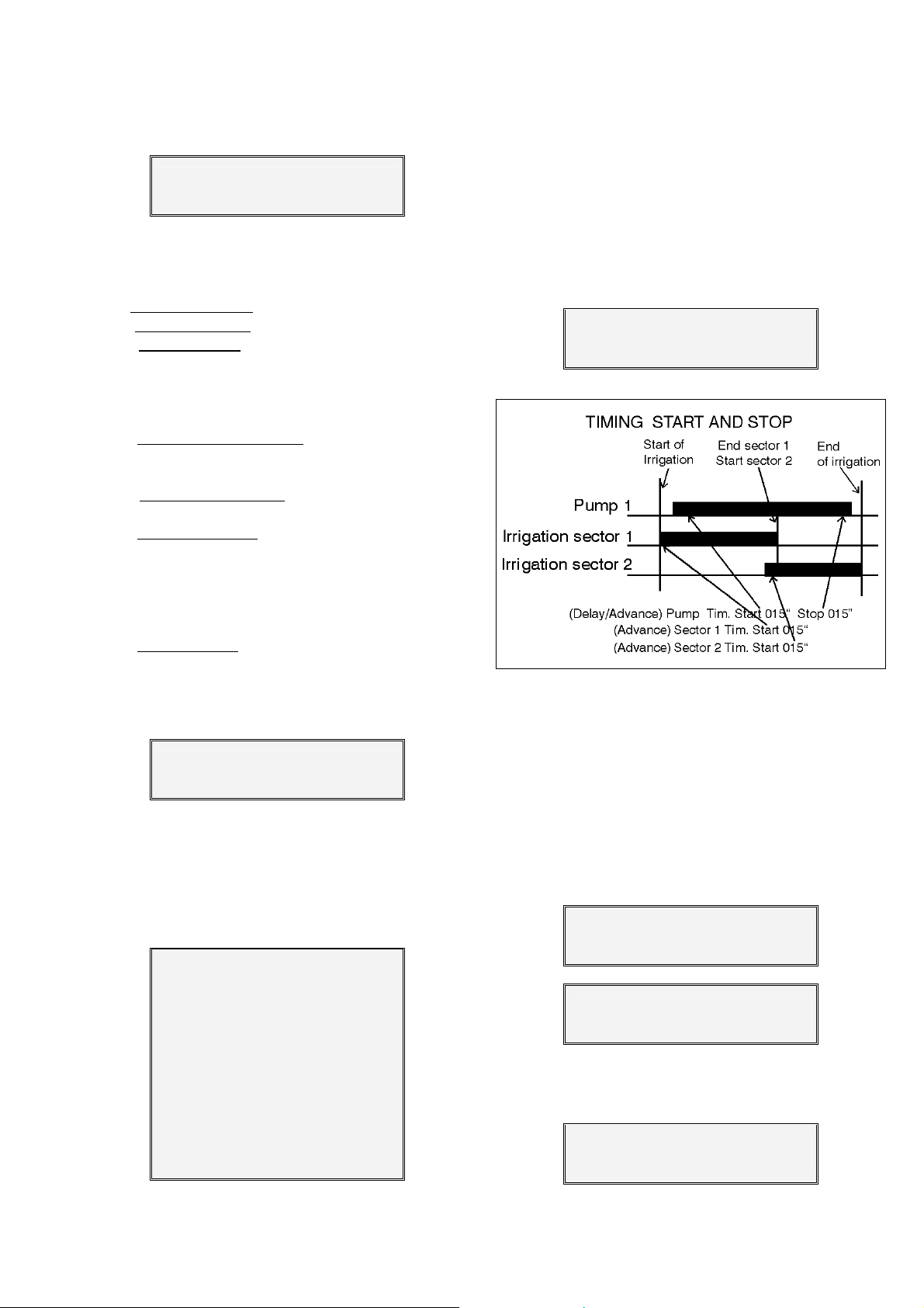
As a precaution against pump water hammer,
there is an advance between the opening of the sector
valves and the start of the pump, between the stopping of the pump and the closing of the valves and a
delay between the closing of one sector and the opening of another.
Valid temporization between 0 and 250 seconds.
Advance/delay
outlets = 005”
To know which terminals are to be connected to
the general outlets, it is necessary to consult the
automatic assignations of the unit in the following
screen.
An outlet not assigned is shown with “--“.
F1, F2, F3, F4 = fertilizers
FP = fertilizer pump (injector)
M1, M2, M3, M4 = mixers
C1-Cx = filter cleaning from filter n.1 to
the last set one
F1 F2 F3 F4 FP
18 17 16 - - 15
M1 M2 M3 M4 C1 - C3
- - 14 - - - - 13 11
To assign sectors to the groups, respond affirma-
tively to the question.
Enter groups
(Yes/No)= Yes
Page 14
14
Between 1 and 4 sectors may be associated to
the four groups.
Group 1 :
02 03 06 00
In the program referring to the groups of sectors,
we will add 70 to the number of the group, group 1 =
71, group 2 = 72, etc. In the example on the previous
screen, a program will activate sectors 2, 3 and 6
when the value 71 is programmed in the risk sector
section.
6.4. CLOCK PARAMETERS
The CLOCK option of the Parameters is used to
enter or modify the day of the week and the time.
To synchronize the seconds, do not press the
ENTER key at the minutes until the real seconds are
00.
Enter: Day, Hour, Min.
Mon.17:43
Next, the following screen is displayed, asking if
the clock should be interrupted in case of a failure in
the power supply.
Clock stop on power
failure, Yes/No = No
If we choose the clock to be interrupted (answering “yes”), a cut in the supply will stop the clock, and
the programs in progress at the moment, and it will
not start again until the current returns.
In this case, all the programs will be completed,
although it will not be in real time. The user should
correct the clock, as soon as possible after the cut.
If, on the other hand, the non interruption of the
clock is chosen, then if the cut in the supply is less
than 24 hours, when it returns, the unit will take up the
program at the corresponding chronological point. If
the shortcut is for more than 24 hours, when it returns,
all the outlets will be deactivated in wait for another
start.
SUMMARY PARAMETERS SCREENS
FERTILIZATION FILTER CLEANING VARIOUS CLOCK
Number of
fertilizers, 0 to 4 = 3
Minutes of
post-irrigation = 05
Minutes of
separation = 02
Fert. Pump (Y/N) = Yes Irrigation minutes
Mixer 2 = Yes
Mixer 3 = Yes
Mixer 4 = No
Minutes of
pre-mixing = 02
Mixing minutes
on / off = 02 / 10
Advance/Delay
F1 F2 F3 F4 FP
M1 M2 M3 M4 C1- C3
Number of
By volume (Y/N) = Yes Enter: Day, Hour, Min.
filters = 3
Working time
per filter = 067”
Pause
between filters= 07”
Irrigation pulse
value = 01000 L.
Fertilizer pulse
value = 0100 cl.
IC FC SC TM GM CS PS
bet. cleaning =0120
1 2 0 5 0 3 4
Stop sectors = No TM Input detection
delay = 025”
GM Input detection
delay = 150”
CS Input detection
delay = 008”
PS Input detection
delay = 300”
outlets = 005”
12 11 10 -- --
09 -- -- 08 06
--
Enter groups
(Yes/No)= Yes
Group 1 :
02 03 06 00
Mon. 17:43
Clock stop on power
failure, Yes/No = No
Mixer 1 = Yes
Page 15
6.5. ADDITIONAL INFORMATION FOR DIESEL OPTION PARAMETERS
The oil pressure gauge “OP” will be connected
to input n.5. It has a double function, first it detects the
engine starting and, once the engine has started, it
detects the malfunctions of oil pressure of the engine.
At the section various parameters, it will ask if it is
necessary to realize pre-heating and if there is a generating set with electro-pump.
Pre-heating
(Yes/No) = No
Electropump
(Yes/No) = Y
To know which terminals are to be connected to
the outlets of the diesel option, it is necessary to consult the automatic assignations of the unit in the following screen.
St = Start outlet.
Sp = Stop outlet.
Pr = Pre-heating outlet
Ep = Electro-pump outlet.
15
St Sp Pr Ep
18 17 16 15
In the diesel version it asks for the start and stop
times.
When temporization the stop, it is advisable to
give it some extra time, to ensure the stop.
Setting the start up seconds at 0 will cancel the
control for the engine start and the oil pressure switch.
Starter time= 04”
Stop time= 035”
When the unit will be prepared to realize pre-
heating, it will ask the working time for pre-heating.
Pre-heating = 12”
In the diesel version with electro-pump control, it
will ask for the delay of the electro-pump once the
diesel engine (P.) has started and the delay to stop
the diesel engine when the electro-pump finishes.
P. input delay= 240”
P. end delay= 050”
Page 16
16
7. USE
This is the chapter the user should mainly know
as it contains the instructions which will be used more
frequently.
Press the FUN key (Functions) to do anything
with the controller, except “consult”.
The following screen with the first two options will
appear:
FUN:”1” = PROGRAMS
FUN:”2” = MANUAL
The PROGRAMS function is used to enter, erase
or read the automatic working orders.
The MANUAL function is used to activate and
deactivate at the moment, manually.
On pressing the FUN key again, the following
screen appears with the other two options:
FUN:”3” = PARAMETERS
FUN:”4” = TOTALS
The PARAMETERS function is used to adapt the
unit to the particular necessities of every installation.
The TOTALS function is used to consult the total
working units in general and sector by sector.
7.1. PROGRAMS
The PROGRAMS function is used to enter, erase
or read the automatic working orders.
The memory of the controller has a capacity for
31 independent or sequential programs.
An “independent program” is a complete working order which includes:
The number or reference of the program; the irrigation sector
week when it should be repeated; the starting
the duration of the irrigation
of the fertilizers
Choosing option n.1 of the FUNCTIONS menu,
the screen will ask for the program number.
to be activated; the day or days of the
time;
and the duration of each
(if there are any).
P00
Introducing the desired number, all the information of this program will be displayed. With the key
marked with an upwards arrow, the different programs
will be displayed.
When the program has been chosen, and the
ENTER key pressed, we are now inside and the
screen will
cursor ( _ ) on every one of the values.
value, it will show a zero plus the new figure.
Complete screen of programs:
ual.
have not been configured as general outlets in “PARAMETERS”. There is the possibility of working with
four sector groupings that are identified by the codes
71 to 74. To do this, the risk sector will be substituted
by the number of the group. In “Parameters – Various”
the sectors are assigned to the group.
TER, this program will be erased after confirmation (as
explained in the Erase section 7.1.4.).
dicated with a spot (inactive day) or with the initial of
the corresponding day (active day). They become
active or inactive pressing the key of the corresponding day and ENTER.
chosen. Press the Daily key to activate or deactivate
all the days.
to 23:59 hours). The 00:00 value is not valid as irrigation starting time. A program can be started by an
order of the PS input (program start), setting the starting time at the 88:00 value.
hours and 59 minutes, and the time of every fertilizer
can go from 1 minute to 9 hours and 59 minutes.
ask for the remaining details, placing the
After introducing the first figure of an existing
Program number
Irrigation sector number
Days of the week
P07 03 S .T.T F . 10:30 Starting time
I04:30 F1 1:30 F2 0:52
Time fertilizer 2
Time fertilizer 1
Irrigation time
The volume is explained in section 8 of this man-
The unit will only accept sector numbers which
If two zeros (00) are introduced followed by EN-
Every day of the week (starting at Sunday) is in-
One, various or every day of the week can be
The starting time is on the 24 hour system (00:01
The irrigation time can go from 1 minute to 99
Page 17
17
After entering the last data of a program, the cur-
sor will be placed again in the program number.
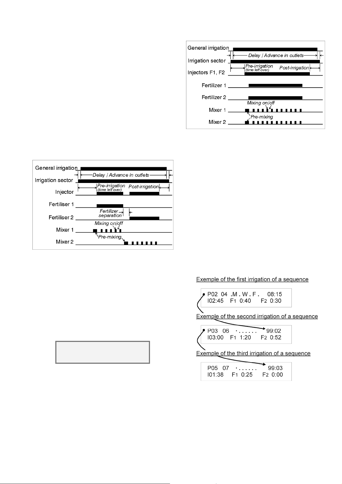
In series fertilization, the sum of the times of different fertilizers and plus the configured post-irrigation
time, plus the separation time between fertilizers (if
more than one is used), must be inferior or equal to
the irrigation time.
The controller calculates this value when the last
fertilizer has been programmed and, if the total is incorrect it will ask for the first fertilizer again.
The controller automatically distributes the fertilizer in the following way (if only one fertilizer is programmed it will occupy the second place in the example).
When the fertilizer number is 3 or 4 the program
information it is distributed in 2 screens, one for the
fertilizers 1 and 2, plus a second for the rest. The two
screens have in common the sector, day, start hour
and irrigation time.
Thereby, when more than two fertilizer will be
programmed, always it will shown two screens by program. The two of them will be similar with the only
difference of fertilizers as it is in the example, that it is
the second screen of program 7 showed in the last
example.
Parallel fertilization is only possible within a single program. If fertilizations have been program-med
in various programs which coincide in time, fertilization error will occur.
7.1.1. Sequential programs
When various sectors have to be irrigated, one
after the other, the SEQUENTIAL PROGRAMMING can
be used. This consists on completely filling in the program for the first sector as shown in the previous section (7.1.), and omitting the days and operating times
of the following programs.
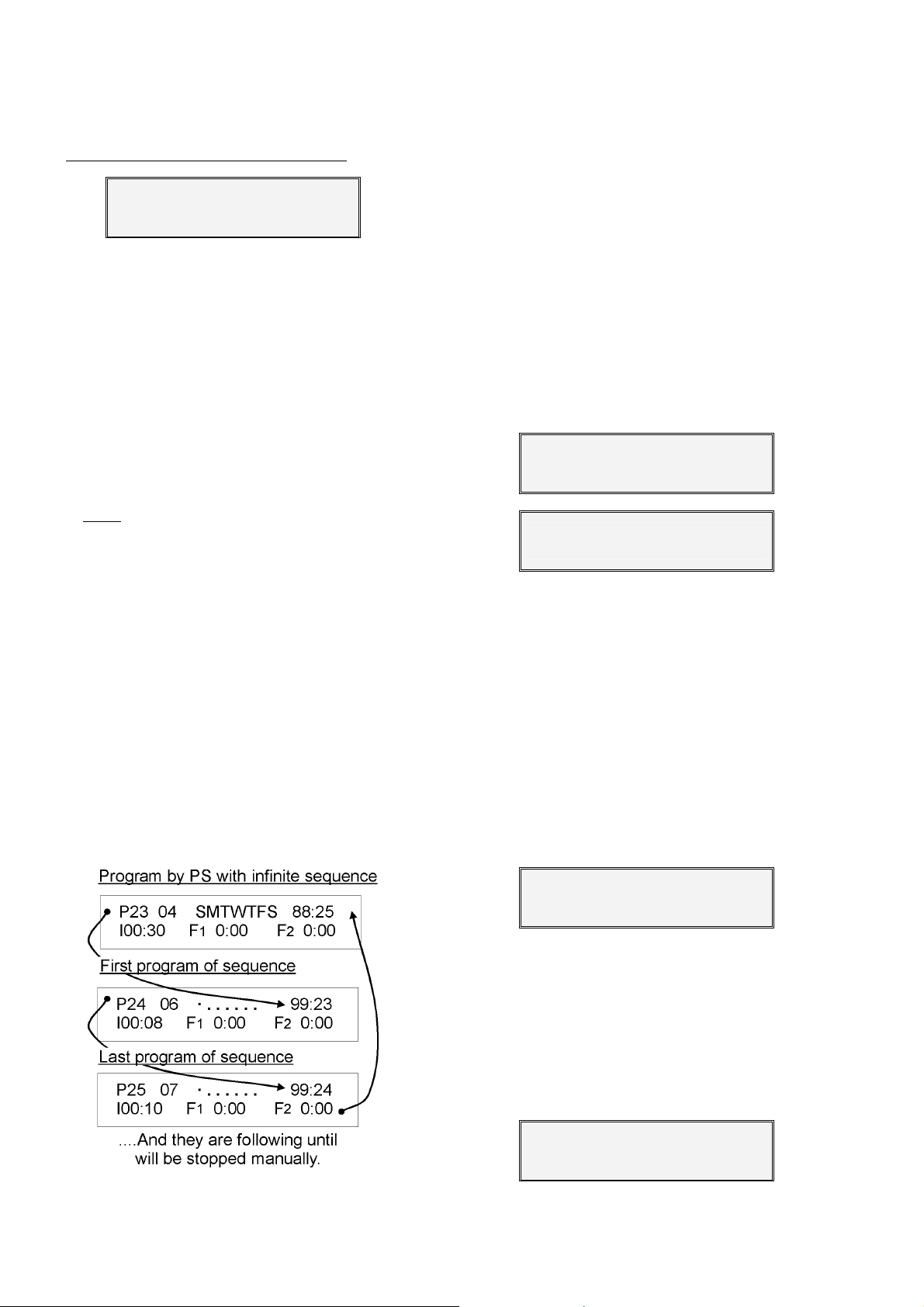
To convert a program into sequential with another, the code “99” must be entered in place of the
starting hour, and the number of the program which
precedes and initiates it in place of the minutes of the
starting time. In this case, it is not necessary to enter
the days of the week.
P07 03 S . T . T F . 10:30
I04:30 F3 0:25
For the fertilization in parallel, first of all in “installer configuration”, it has to be defined that the fertilizers will be injected like this. The programming will
be the same as in series.
The fertilization in parallel can be done through a
multihead injector or with one injector for each one of
the installation fertilizers.
The fertilizer will be applied like it is shown in the
next picture.
In the previous example, we can see that program
n.2 will irrigate sector 4 on Mondays, Wednesdays and
Fridays at 8:15; program n.3 will irrigate sector 6 at the
end of program n.2 and program n.5 will irrigate sector 7
when program n.3 finishes.
When we want to stop a program sequence (which
will not work until new order, but without erasing), it is
sufficient to cancel the days of the week of the first pro-
Page 18
18
gram of the sequence. To reactivate it, the day or days
of the week should be re-entered.
Example of stop of the previous sequence
P02 04 · . . . . . . 08:15
I02:45 F1 0:40 F2 0:30
When a sequential program is running and there is
a TM temporary stop, the program running will stop and
it will continue into the next sequence.
If the malfunction did not disappear, all the subprograms of the sequence would not be executed and
this would be recorded.
7.1.2. Program start by input
If an input for program start PS has been configured, the irrigation program can be started by external
order (thermostat, humidistat, level, etc.). In order to do
so all the days of the week have to be entered and the
code 88:00
identify the fact that the program will be started by external order.
and its sequences have finished.
programs activated by external order will be required,
the start program have to have the code 88 in the start
hours position and the last program of the sequence in
minutes. When the start program will be finished, the
next program of the sequence will start independently of
the input PS state, having the programs in an infinite
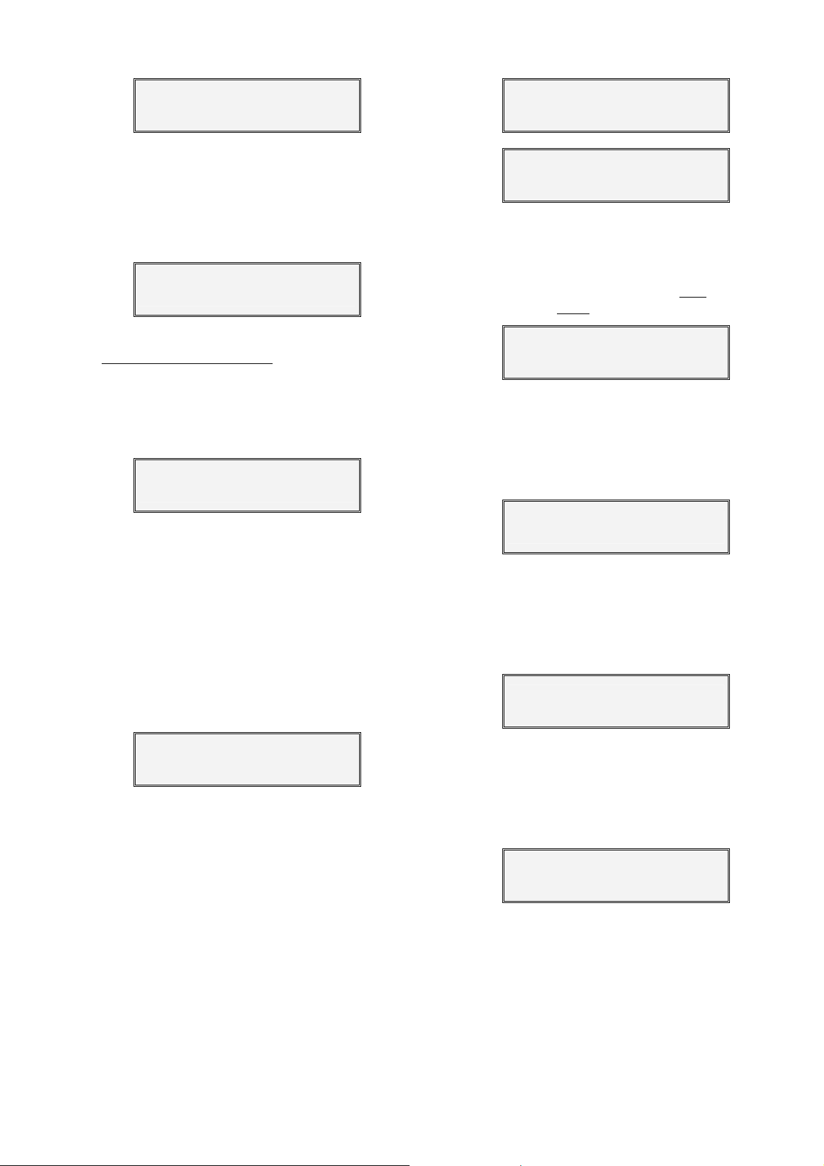
sequence. Once the start program will be started the
code 88 for PS will actuate as code 99 of sequence.
external order in case of anti-frost.
has to be introduced at the starting time, to
The start input PS will not re-start until the program
In case of a infinite sequence of several irrigation
The irrigation have to be stopped manually.
Sequence example of three programs started by
7.1.3. Program by frequency activation
In order to make different irrigations activations in
one sector or in a group of sectors, only the program 1
have the variable of activation number and frequency
between them.
The frequency time between activations may be
“hours:minutes”, or “hours”, depending on the selection made in the installer’s configuration.
To realize more than one activation, when the signal will be in the weekly days, it should be pulsed the
key “arrow”, will be shown the activation values.
Let see and example for sector 4, irrigation all the
days of a week with 3 activations each 3 hours 45 minutes; starting the first activations at 8:15 the second one
at 12:00 and the last one at 15:45; the irrigation time for
every activation will be 1 hour 30 minutes.
P01 04 SMTWTFS 08:15
I01:30 F1 0:12 F2 0:22
P01 04 03 – 3:45 08:15
I01:30 F1 0:12 F2 0:22
If it is necessary irrigate more sectors in a sequence, only is needed to link programs with the first
one in order to use this activations. The program 1 will
continue its activations independently of the programs
that are in the sequence.
When the irrigation time will be superior to the frequency time between activations, the program 1 will not
start again until the irrigation time will be finished, keeping in “view” the frequency time in 0:01.
In view, it will show the information of pending activations to realize and the time (frequency) to realize the
next one. If there is no activations pending, nothing will
be shown in the view screen.
P01 Activations : 02
Frequency : 1:53
7.1.4. Erase
If we want to erase a program, when the screen
asks for the sector number, enter two zeros (00) and
ENTER, being followed by a confirmation screen.
If we confirm with the “YES” key, the program will
be erased. If the “NO” key is pressed, the previous
screen will reappear.
P07 00
Page 19
19
Erase previous
program (Yes/No) ?
7.2. MANUAL
If we choose Function 2 (MANUAL) of the functions
menu, this screen will appear asking what we want to do
with the manual control.
System:1 In course:2
Prog.:3 Clean.:4 Outl:5
The first option “System”, allows the unit to work,
but the outlets are disconnected
“ENTER”.
However, if it is in the Consultation section, the following screen will be shown to inform that it is at “manual stop of the system”. From here, to finish press “ENTER”.
WARNING !
Manual system stop
The second option is “stop in course”. With this option we can cancel the irrigation units which are to be
applied and which correspond to the programs which
are being carried out in this moment.
With the third option “programs”, a program can
be activated or deactivated. The number program will be
asked: if the program is already working, it will be
stopped, if it is not working, it will start it.
In sequential programs, the chosen program will
be activated and, on finishing, the sub-program which
follows will also be activated, and so on, until the sequence has finished.
Program number = 00
Option number 4 “cleaning” activates the filter
cleaning, or it stops it if it is already working.
Option 5 “outlets” activates any outlet of the controller. The outlet is asked, allowing a maximum of 6.
The general outlet has number “99”.
This option has to be used very carefully, due to
the fact that when an outlet is activated in this way, the
control of malfunctions, anomalies, totals, etc. is not
carried out.
To cancel them, enter the outlet number again, and
it will deactivate.
In the CONSULT screen, ”MANUAL” will be displayed to show that an outlet is activated in this way.
In case of power cut all the outlets will be cancelled.
. To stop, press “1” and
Outlet number = 00
08 03 00 00 00 00
Mon.18:14 - MANUAL -
7.3. TOTALS
If option n.4 of the Functions menu is chosen, this
screen will appear asking if we want to read
lated quantities or erase
them.
TOTALS
Reading:1 Erasure:2
If “Reading” has been chosen, this screen will appear showing the hours and minutes of water application in all the sectors, and also those of fertilizers number
1 and 2 (General).
When various sectors work simultaneously, only
the data of one of them is accumulated.
- General - I = 0087:51
F1 = 0012:05 F2 = 0009:24
If with the previous screen, ENTER or the arrow key
are pressed, this screen appears with the information of
the sectors.
If we continue pressing the key arrow, the information of the other sectors is displayed.
To finish, press the FUN or VIEW key.
Sector: 01 I=0023:12
F1= 004:35 F2=0003:09
If there are more than 2 fertilizers, the information of
a sector or the general one, it will shown in two screens,
F1-F2 in the first one and F3-F4 in the second one.
If on the first Totals screen, the ERASURE option
has been chosen, then this screen will appear asking
if the general total is to be erased.
Erase everything
(Yes/No) = No
the accumu-
Page 20
20
7.4. CONSULTATION
The work of the controller can be reached with the
VIEW key.
Pressing the VIEW key several times, different mes-
sages and data will appear on the screen.
In the first touches of the VIEW key, messages
about different anomalies which the unit has suffered
might appear (this will be seen later).
If the controller has not suffered any anomalies, it
will show the data of the work being carried out at that
moment.
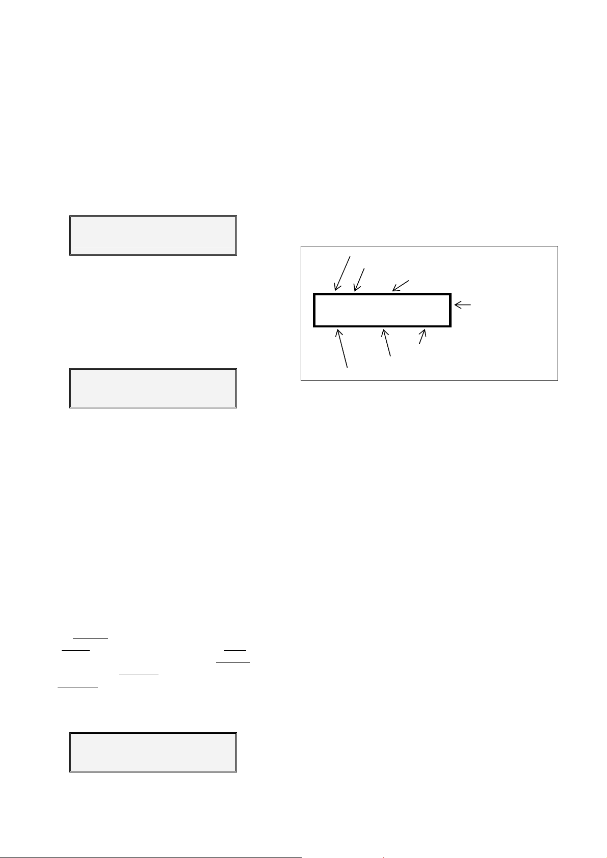
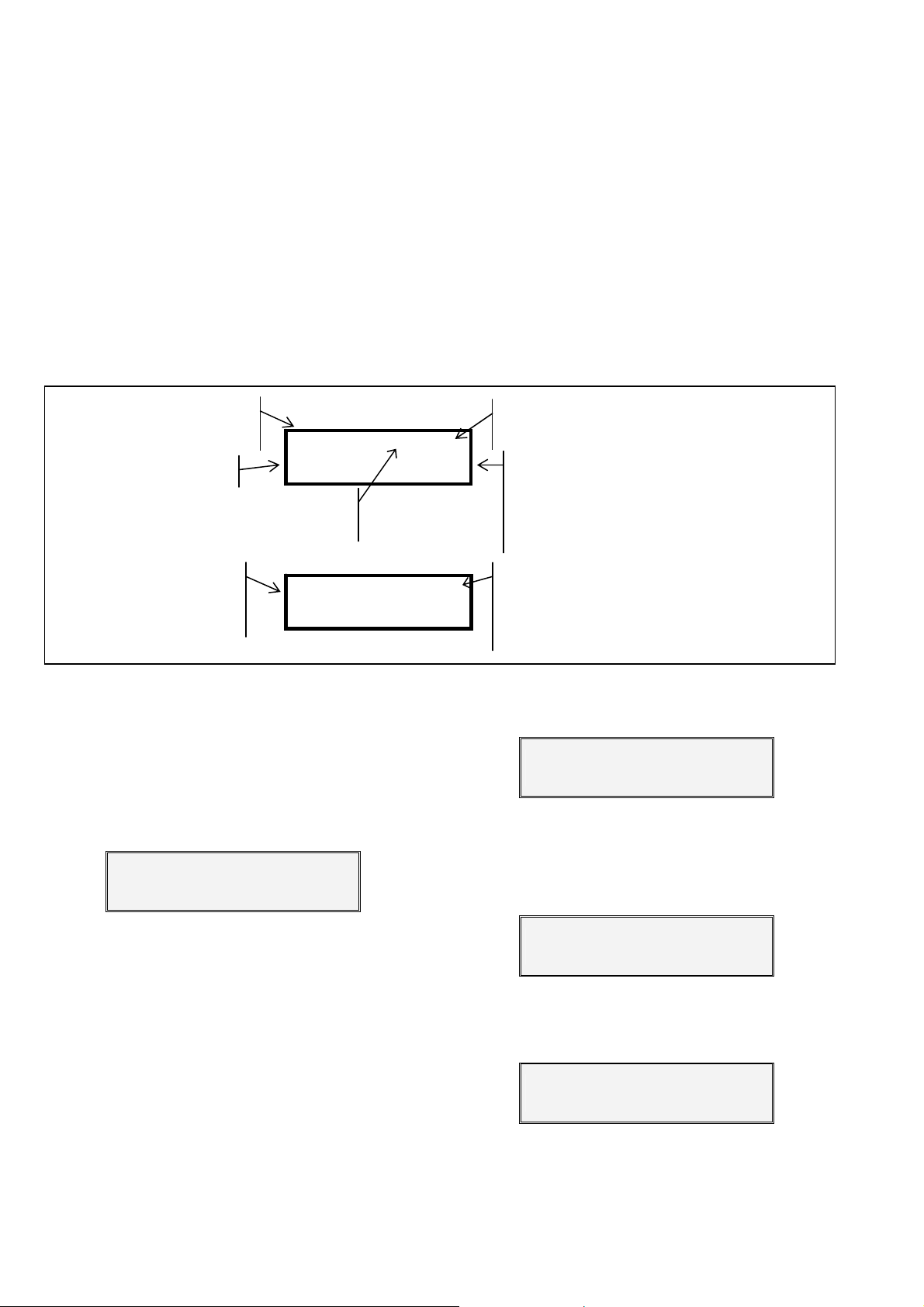
In the first consult screen the clock will appear, together with the state of the 5 inputs, the irrigation sectors
and the general outlets.
Day of week, hour and
minute of the clock
Activated sectors
“Manual”=manual activation of outlets
“COND. STOP”=conditional stop
Mon.18:20 I..34.
02 03 F
1F3m C1
We have to take into account that every input has a
function assigned in the “parameters” section.
If the filter cleaning is being carried out, the fertilizer
(if there is one) is stopped temporarily and the unit will
not accept either temporary nor general malfunctions.
If there is a sector being irrigated, pressing “VIEW”
again will make another screen appear with detailed
information of every sector.
If there are more than two sectors being irrigated,
rd
and 4th will appear on the screen after pressing
the 3
“VIEW” again.
Pressing “VIEW” again, the unit will start the consultation cycle again.
Input state:
. = deactivated, nº = activated
General outlet state
1 / F2 /F3 /F4 = activated fertilizer
F
. = Fertilizer pending
(preirrigation, separation)
m = Fertilizer mixer running
C1 = cleaning of filter nº
For every two activated sectors, a screen with their
valves will be displayed.
S02 P14 F1 0:08 F2 0:19
I=01:58
F3 0:21 F4 0:15
7.4.1. Anomalies
On pressing the “VIEW” key, if there are any
anomalies, the first will be shown on the screen, if not, it
will go to general consultation (7.4.).
On having an anomaly on the screen and pressing
“VIEW”, the unit will ask if we want to erase it. Answer
yes or no.
Erase previous
anomaly (Yes/No) ?
Up to ten screens with recorded anomalies may
appear. If there are more than 10, the last one would
always remain recorded on the tenth screen.
The anomalies that the unit can store in its memory
are:
- POWER SUPPLY FAILURE.
- TEMPORARY MALFUNCTION.
- FERTILIZER LEFT OVER.
- PROGRAM DOES NOT ENTER.
- FERTILIZER DOES NOT ENTER.
- INTERFERENCE.
The unit records power cuts superior to a minute
inferior to 24 hours. The following screen informs
and
In the first line shows the sector nº, program
nº with the values of the F1 / F2 units left, and
in the second line the irrigation time left and
the F3 / F4 units left.
that there was a cut in the power supply from 12:57 on
Monday to 2:45 on Tuesday.
* Power cut *
Mon.12:57- -Tu.02:45
Every time a program finishes through the input of
temporary malfunction, a recording takes place. This
anomaly indicates a stop for temporary malfunction at
23:45 on Monday, canceling the irrigation of program
n.3.
*Temporary malfunction*
Mon.23:45 P03
If at the end of the irrigation program there is fertilizer left over, the following anomaly will be shown, indicating the program and the fertilizer units left.
*Fertilizer left*
P02 F1 0:02 F2 0:34
The following screen informs that program n.14
can not enter as there are already 8 sectors working
simultaneously (the limit of the number of sectors that
Page 21
21
can work at the same time is set in the installer configuration).
*Program not enter*
P14
This screen informs that the fertilizers for program
n.12 can not be entered as it is already being used for
other program (however, the irrigation sector has been
entered).
*Fertili. not enter*
P12
This screen informs that at 05:33 on Tuesday, there
was an electromagnetic or electrostatic interference, restarting automatically.
*Interference*
Tu.05:33
Once all the anomalies have been shown, the
screens with the state of the controller will be displayed.
7.4.2. Malfunctions
If any of the following malfunctions happens, the
controller will automatically flash the message intermittently on the screen until the “ENTER” key is pressed
(maintain the key pressed down for at least one second). Until the malfunction is cancelled, the unit does
not allow any activation of the irrigation programs.
If the general malfunction input was activated, all
the outlets will be deactivated and the screen will show
this message with the day and time when it occurred.
The following screen warns that there has been a
stop of the unit by MANUAL CONTROL, waiting to be
reactivated.
The outlets are deactivated but the program runs
its course.
WARNING!
Manual system stop
On connecting the unit to the mains, this screen
might appear for a few seconds, while the timetable of
the irrigation programs is brought up to date.
Set timetable
10:33
*General malfunction*
Sat.19:01
If this message appears, the internal battery has
completely run down with the loss of the time and the
data of the current operation plus the totals, but not the
irrigation programs.
WARNING!
Set clock
The battery can keep this data for a minimum of 3
days, without external power. The parameters and the
programs are never erased from the memory due to a
cut of the electricity supply.
Page 22

22
8. ADDITIONAL INFORMATION FOR VOLUME
When configuring the unit to irrigate and fertilize in
volume units, m
changes in the “functions” of the controller take place:
8.1. PARAMETERS
In the irrigation programming by time, the preirrigation is calculated automatically from the entered
irrigation value, as the irrigation and the fertilizer are
applied on the same base, which is the minute.
By volume, the pre-irrigation and post-irrigation values have to be entered in “m
It will start to fertilize once the irrigation has finished
the pre-irrigation plus the pre-mixing time, if there is one,
and it will may sure that the fertilizer application does not
overlap with the post-irrigation volume, in this case, the
unit would stop fertilizing and the anomaly would be
recorded.
The volume units in fertilizer parameters are:
- Pre-irrigation 0 to 999 m
- Post-irrigation 0 to 99 m
- Separation between fertilizers 0 to 99 m
The volume units in filter cleaning parameters are:
- Irrigation volume between cleaning cycles:
0 to 9999 m
In various parameters, the irrigation and the fertilization are configured plus the value of the counters (as
already explained in section 6.1.).
8.2. PROGRAMS
The differences in an irrigation program by volume
are:
-Irrigation units 0 to 999 m
-Fertilizer units 0 to 999 liters
3
and liters respectively, the following
3
”.
3
3
3
3
.
3
8.4. CONSULTATION
For every sector being irrigated, it will display the
quantity of cubic meters left to irrigate and the liters of
fertilizer which are still to be applied.
S02 P14 F1026 F2 000
I=083 F3 007 F4 012
8.5. ANOMALIES
If no pulses are received from the irrigation water
counter for more than ten minutes, while any program is
working, the program will be stopped and the following
anomaly will appear.
* I. counter malfunction *
Mon. 11:28
If the controller is fertilizing and no pulses are received from the volumetric fertilizer counter, for more
than ten minutes, the fertilization program being carried
out would be stopped and the following anomaly would
be recorded.
* F. counter malfunction *
Sun. 07:33
P02 04 SMTWTFS 08:15
I084 F1 014 F2 009
The modality of parallel fertilization can not be
done in volume units.
8.3. TOTALS
In the totals, the information will be shown in m3
units for the irrigation and in liters for the fertilizers.
Page 23
23
9. ADDITIONAL INFORMATION FOR DIESEL OPTION
This option increases the functions of the
AGRÓNIC 2000 with the control of an internal combustion engine (diesel or petrol) with an electronic starter.
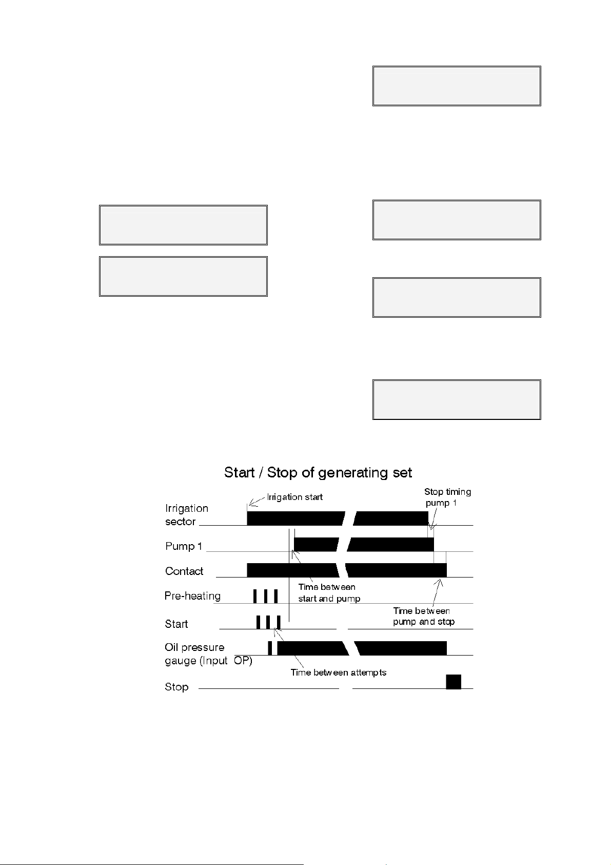
The operating theory is the following: on activating
the first irrigation program, the corresponding irrigation
sector is activated and, after the temporization of the
“advance/delay in outlets”, the pump outlet “M” or contact, is activated and the starter while there is no oil pressure; if there is pressure, a “malfunction” will be activated.
If oil pressure appears during the starter temporization, the attempt will finish after 3 seconds, if it did not on
finishing temporization, not to damage the starter engine.
If, 30 seconds after the attempt at starting, the unit
detects oil pressure, it will stop trying and accept the
malfunction. If after this time there is no pressure, the
unit will try again, and so on up to a total of 4 attempts.
If, after these 4 attempts pressure does not appear, the
program will be omitted and the “starter malfunction”
message will appear.
Pre-heating is carried out prior to starter.
9.1. CONSULTATION
In the first screen of consult the letters OP will be
shown at the end of the first line, to indicate that the
engine is working and there is oil pressure, at the end of
the second line the letters A, S or P will be shown when
the start (“A” for activation), stop or pre-heating takes
place.
When detecting a failure of the oil pressure, an
anomaly will be recorded, showing the day and time
when it took place. The detection is delayed 10 seconds.
* Oil pres. malfunc. *
Mon. 11:15
9.3. MALFUNCTIONS
When the first attempt is made at starting, if the unit
detects that there is already pressure in the pump, all the
outlets will be deactivated, and this message will appear.
* There is oil pressure *
Thu. 10:30
If, while attempting to start up, the unit detects a fall
in the voltage to below 8 V all the outlets are disconnected, and this screen appears, with the day and time
when it took place.
A discharged battery or incorrect wiring could be
causes of this.
* Power failure *
Sat. 08:14
Mon. 18:20 I … ... OP
8 14 F1a C1 ASP
9.2. ANOMALIES
If, having made 4 attempts at the starting and having passed 30 seconds, the engine is not working, the
program is omitted, and the anomaly recorded, showing
the day and time when it took place.
* Malfunction at Start *
Wed. 18:05
Page 24

24
NOTES:
R-1189-3
 Loading...