


Progear 1308.4-090716 User Manual
AIR ELLIPTICAL
1308.4-090716
IMPORTANT:
Retain this owner’s manual for future reference.
The specifications of this product may vary from this photo and, subject to change
without notice.
Read all instructions carefully before using this product.

SERVICE-------------------------------------------------------------------------- 2
TABLE OF CONTENTS
LABEL PLACEMENT---------------------------------------------------------- 3
IMPORTANT SAFETY GUIDELINES-------------------------------------- 4
OVERVIEW DRAWING------------------------------------------------------- 5
PARTS LIST---------------------------------------------------------------------- 6
ASSEMBLY GROUP----------------------------------------------------------- 8
ASSEMBLY GROUP LIST ---------------------------------------------------- 9
HARDWARE & TOOLS PACK----------------------------------------------- 11
ASSEMBLY----------------------------------------------------------------------- 12
COMPUTER---------------------------------------------------------------------- 27
TENSION ADJUSTMENT----------------------------------------------------- 28
LEVEL ADJUSTMENTS------------------------------------------------------- 29
HOW TO USE U SHAPE GRAB BARS----------------------------------- 30
MOVING THE ELLIPTICAL EQUIPMENT-------------------------------- 31
MAINTENANCE----------------------------------------------------------------- 32
TROUBLE SHOOTING-------------------------------------------------------- 33
WARRANTY---------------------------------------------------------------------- 35
PARTS REQUEST FORM---------------------------------------------------- 36

IMPORTANT: FOR NORTH AMERICA ONLY
TABLE OF CONTENTS
2
SERVICE
2
For damaged or defective pr oduc t , questions, replacement parts or any
other service support, please contact our customer service department
(8:00 AM - 5:00 PM Pacific Standard Time, Daily) by the below methods:
For Best Service, please Email:
Service@paradigmhw.com
Response Time: 1-2 Business Days
Website:
www.paradigmhw.com*
ll-Free:
To
1-844-641-7920**
Resp
Please have the following information ready when requesting for service:
Your name
Phone number
Model number
Serial number
Part number
Proof of Purchase
or damaged or defective product please contact our customer service
F
before returning to the store .
Paradigm Health & Wellness, Inc.
onse time may vary.
1 189 Jellick Ave.
City of Industry, CA 91748, USA
3
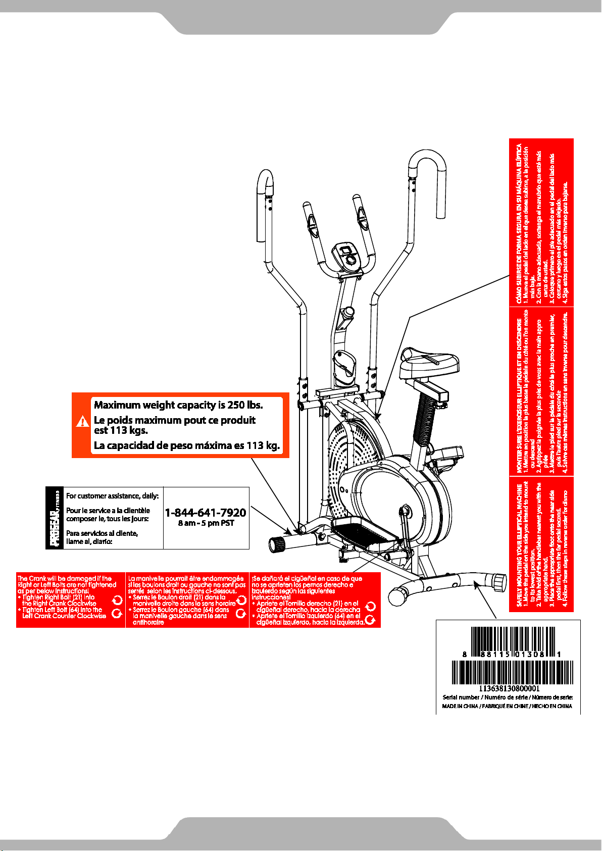
LABEL PLACEMENT

B
4
IMPORTANT SAFETY GUIDELINES
asic precautions should always be followed, includin g the following safety
instructions when using this equipment. Read all instructions bef ore using this
equipment.
1. Before exercising and to avoid injuring your muscles, it is highly recommended
that you perform warm-up exercises for each muscle group. Please refer to
Warm Up section of the Owner’s Manual.
2. Please make sure all components are not damaged an d are working order
before using. This equi pment sh ould b e place d on a stable, flat surface. Using a mat
or similar material on the ground is recommended.
3. Please wear proper clothes and shoes when using this equipment. Do not
wear loose clothing that may get caught by any part of the equipment.
4. Only perform maintenance or adjustments that are instructed in this manual.
Should any problems arise, discontinue use and consult with customer service
at Paradigm.
5. Be careful when stepping on or stepping off the pedals. Always hold onto the
handlebars first and make sure the pedal at your side is at its lowest position,
then step on. With your other leg, stride over the main frame and come to rest
onto the other pedal. To ensure the pedals run smoothly, push or pull on the
handlebars first, then follow with leg motion. To dismount, reduce pedaling
speed gradually before you stop. When stepping off the machine, make sure
one pedal is at its lowest position and step out of there before stepping out of
the pedal at the highest position.
6. Keep dry - do not operate in wet or moist condition.
7. Do not use the equipment outdoors.
8. This equipment is for household use only.
9. Only one person should be on the equipment at a time.
10. Keep children and pets away from the product at all times.
11. This machine is designed for adul ts onl y.
12. This product requires a minimum of 6 feet of space for safe operation.
13. If you feel any chest pains, nausea, dizziness, or short of breath, you should
stop exercising immediately and consult with your physician before continuing.
14. The maximum weight capacity for this product is 250 lbs/113 kgs.
WARNING: Before beginning any exercise program consult your physician.
This is especially important for the people who are over 35 years old or who have
pre-existing health problems.
CAUTION: Read all instructions carefull y before operating this product.
Retain this Owner’s Manual for future reference.
5
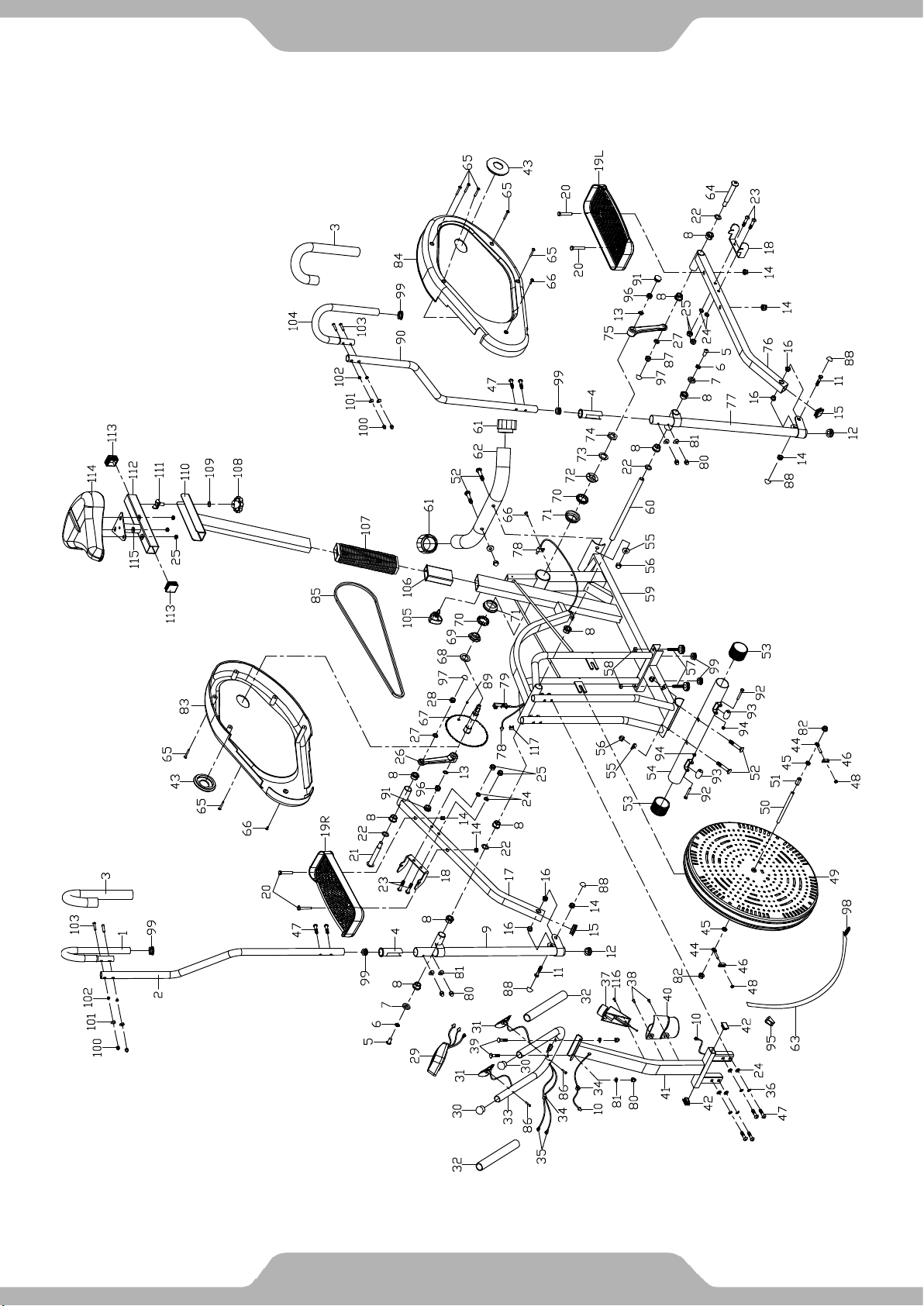
OVERVIEW DRAWING

No.
Description
Qty
No.
Description
Qty
001
Right U Shape Grab Bar
Ø25x1.8
002
Right Handrail Arm Ø25x1.8
1
029
Computer M1202
1
U-Shaped Grab Bar Foam Grip
Ø24xØ34x410
Hand Pulse Handlebar End Cap
Ø25x1.5
Handrail Arm Plastic Bushing
Ø32x1.5
Hand Pulse Handlebar Foam Grip
Ø24xØ30x240
006
Spring Washer Ø10xØ18x3
2
033
Hand Pulse Handlebar Ø25x1.5
1
007
Washer Ø28xØ16xδ5
2
034
Wire Grommet Ø12.1
2
Powder Metal Bushing
Ø24.5xØ16x14
Hand Pulse Sensor Wire
L=500 mm
009
Right Handrail Ø32x1.5
1
036
Spring Washer Ø8
4
Extension Sensor Wire
L=650 mm
011
Bolt M10x55
2
038
Bolt M5x15
2
012
Handrail End Cap Ø32x1.5
2
039
Carriage Bolt M8x35
2
Serrated Lock Was her Exter nal
Teeth Ø10
Hand Pulse Handlebar Support
Frame
Hand Pulse Handlebar Support
Frame End Cap 30x20x2
Powder Metal Bushing
Ø14xØ10x10
017
Right Foot Bar
1
044
Eyebolt M6x33
2
Foot Pedal Support Bracket
245x38xδ3.0
019L
Left Foot Pedal 349x150x56
1
046
Tension Bracket
2
019R
Right Foot Pedal 349x150x56
1
047
Bolt M8x38
8
020
Bolt M10x45
4
048
Nut M6
2
Right Bolt for Right Crank
Ø16x89xL23
Fan Wheel Ax le
M10x1xL150xL25xL40
023
Bolt M8x43
4
051
Spacer Ø16xØ10x20
1
024
Washer Ø8
8
052
Bolt M10x57
4
025
Nylon Nut M8
7
053
Front Stabilizer End Cap Ø50
2
026
Right Crank 6.7"
1
054
Front Stabilizer Ø50x1.5x540
1
027
Spring Washer Ø20xØ13x2
2
055
Curve Washer Ø10xØ25x2
4
6
PARTS LIST
1 028 Nylon Nut for Right Crank 1/2” 1
003
004
005 Bolt M10x18 2 032
008
010
013
014 Nylon Nut M10 6 041
015 Foot Bar End Cap 30x30x1.5 2 042
2 030
2 031 Hand Pulse Sensor 2
10 035
1 037 Tension Control Knob L=40 mm 1
2 040 Bottle Holder 1
2
2
2
1
2
016
018
021
022 Wave Washer Ø28xØ17x0.3 4 050
4 043 Cover Cap Ø25 2
2 045 Nut M10x1xB5 2
1 049 Fan Wheel Ø503x85 1
1

No.
Description
Qty
No.
Description
Qty
056
Cap Nut M10
4
088
Nut Cap S16
4
057
Adjustable Leveler M8x45
2
089
Small Magnet Ø15x7
1
058
Nut M8
2
090
Left Handrail Arm Ø25x1.8
1
059
Mainframe
1
091
Crank Cover Ø22
2
060
Rotation Rod Ø15.8x376
1
092
Bolt M6x45
2
061
Rear Stabilizer End Cap Ø50
2
093
Transp ort Wheel Ø23xØ6x32
2
062
Rear Stabilizer Ø50x1.5x550
1
094
Nylon Nut M6
2
063
Tension Strap 1150x18
1
095
Plastic Clip 20
1
064
Left Bolt for Left Crank
Ø16x89xL23
065
Screw ST4.8x40
7
097
Nut Cap S18
2
Phillips Self Drilling Screw
ST4.8x20
067
Chain Pulley
1
099
Round Plug Ø25x1.5
6
068
Washer Ø40x24x3
1
100
Cap Nut M6
4
069
Bearing Nut II 15/16"
1
101
Big Curve Washer Ø6xØ16x1.5
4
070
Bearing
2
102
Conical Washer Ø6xØ10.5x 5
4
071
Bearing Cup
2
103
Bolt M6x30
4
072
Bearing Nut I 7/8"
1
104
Left U Shape Grab Bar Ø25x1.8
1
073
Washer Ø34.5x23x2.5
1
105
Seat Post Knob M12
1
074
Nut 7/8"
1
106
Seat Post Plastic Bushing
1
075
Left Crank 6.7"
1
107
Seat Post Plastic Tube
1
076
Left Foot Bar
1
108
Seat Adjustment Knob M10
1
077
Left Handrail
1
109
Washer Ø10xØ20x2
1
078
Sensor with Wire L=900 mm
1
110
Seat Post
1
079
Tension Cable L=1020 mm
1
111
U Shape Bolt M10
1
080
Cap Nut M8
6
112
Seat Sliding T ube
1
Seat Sliding Tube End Cap
38x38x1.5
082
Flange Nut M10x1xB10
2
114
Seat Cushion DD-98-4T
1
083
Right Cover 705x362
1
115
Big Washer Ø8xØ20x 2
3
Cross Recessed Pan Head Screw
M5x15
085
Chain
1
117
Clip
1
7
PARTS LIST
1 096 Flange Nut M10x1.25 2
066
081 Big C urve Washer Ø8xØ20x2 6 113
3 098 Spring Ø12x1.8x32 1
2
084 Left Cover 705x362 1 116
086 Screw ST4.2x20 2
087 Nylon Nut for Left Crank 1/2” 1
1
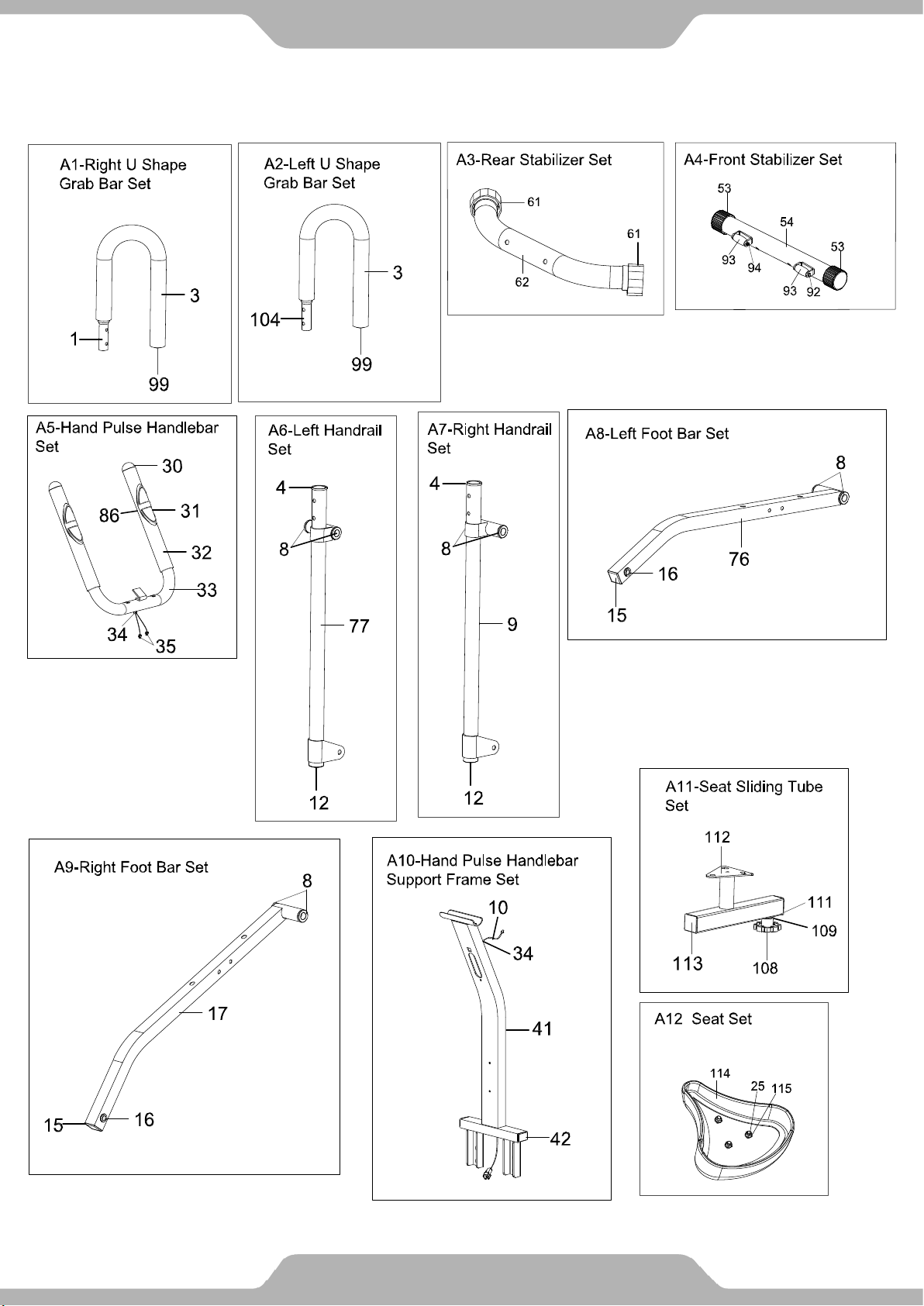
8
ASSEMBLY GROUP

Assembly
Group
A1
1
Right U Shape Grab Bar Ø25x1.8
1
99
Round Plug Ø25x1.5
1
3
U-Shaped Grab Bar Foam Grip Ø24xØ34x410
1
104
Left U Shape Grab Bar Ø25x1.8
1
99
Round Plug Ø25x1.5
1
3
U-Shaped Grab Bar Foam Grip Ø24xØ34x410
1
62
Rear Stabilizer Ø50x1.5x550
1
61
Rear Stabilizer End Cap Ø50
2
54
Front Stabilizer Ø50x1.5x540
1
53
Front Stabilizer End Cap Ø50
2
92
Bolt M6x45
2
93
Transp ort Wheel Ø23xØ6x32
2
94
Nylon Nut M6
2
33
Hand Pulse Handlebar Ø25x1.5
1
30
Hand Pulse Sensor
2
32
Hand Pulse Handlebar Ø25x1.5
2
31
Hand Pulse Handlebar Foam Grip Ø24xØ30x240
2
86
Screw ST4.2x20
2
34
Wire Grommet Ø12.1
1
35
Hand Pulse Sensor Wire L=500 mm
2
4
Handrail Arm Plastic Bushing Ø32x1.5
1
8
Powder Metal Bushing Ø24.5xØ16x14
2
77
Left Handrail
1
12
Handrail End Cap Ø32x1.5
1
4
Handrail Arm Plastic Bushing Ø32x1.5
1
8
Powder Metal Bushing Ø24.5xØ16x14
2
9
Right Handrail Ø32x1.5
1
12
Handrail End Cap Ø32x1.5
1
8
Powder Metal Bushing Ø24.5xØ16x14
2
15
Foot Bar End Cap 30x30x1.5
1
16
Powder Metal Bushing Ø14xØ10x10
2
76
Left Foot Bar
1
8
Powder Metal Bushing Ø24.5xØ16x14
2
15
Foot Bar End Cap 30x30x1.5
1
16
Powder Metal Bushing Ø14xØ10x10
2
17
Right Foot Bar
1
9
ASSEMBLY GROUP LIST
A2
A3
A4
A5
No. Description Q’TY
A6
A7
A8
A9

Assembly
Group
A10
41
Hand Pulse Handlebar Support Frame
1
34
Wire Grommet Ø12.1
1
10
Extension Sensor Wire L=650 mm
1
Hand Pulse Handlebar Support
Frame End Cap 30x20x2
113
Seat Sliding Tube End Cap 38x38x1.5
2
112
Seat Sliding T ube
1
111
U Shape Bolt M10
1
108
Seat Adjustment Knob M10
1
109
Washer Ø10xØ20x2
1
114
Seat Cushion DD-98-4T
1
115
Big Washer Ø8xØ20x 2
3
25
Nylon Nut M8
3
10
ASSEMBLY GROUP LIST
No. Description Q’TY
A11
A12
42
2
11
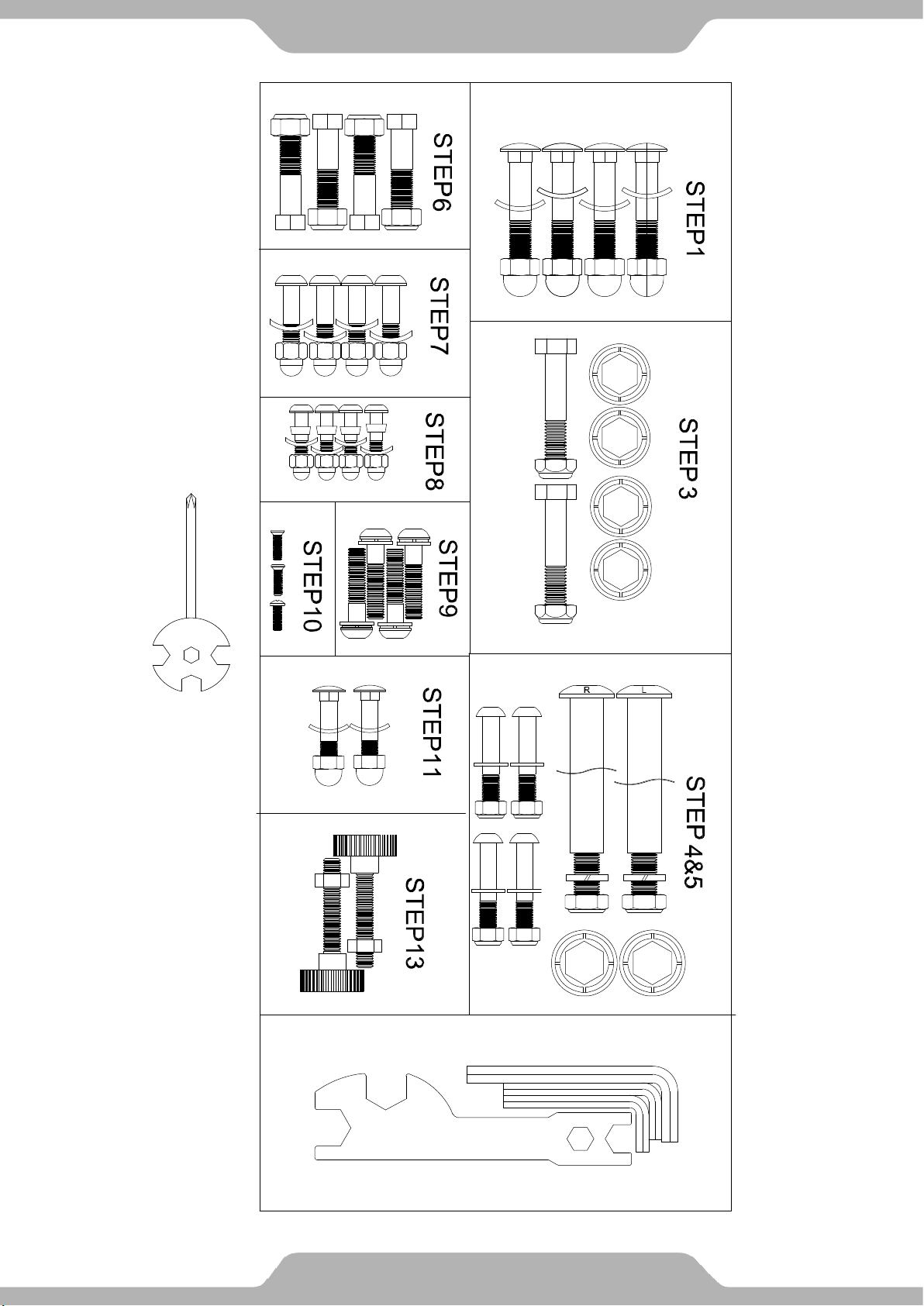
HARDWARE & TOOLS PACK
Multi Hex Tool with Phillips Screwdriv er
S10, S13, S14, S15
1 PC