

Page 1
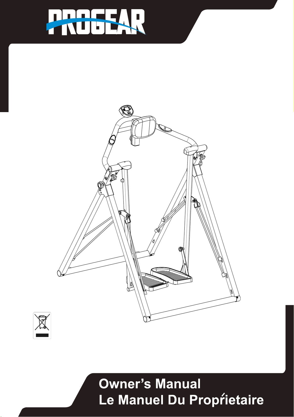
AIR WALKER
IMPORTANT: Read all instructions carefully before using this product.
Retain this owner’s manual for future reference.
The specifications of this product may vary from this photo and, subject to change
without notice.
Item#3410
Page 2

3410.2‐102615
Page 3

TABLEOFCONTENTS
SERVICE ---------------------------------------------------------------------- 2
LABEL PLACEMENT ------------------------------------------------------- 3
IMPORTANT SAFETY INSTRUCTIONS ------------------------------ 4
OVERVEW DRAWING ----------------------------------------------------- 5
PART LIST -------------------------------------------------------------------- 6
ASSEMBLY ------------------------------------------------------------------- 7
TENSION ADJUSTMENT ------------------------------------------------- 11
COMPUTER ------------------------------------------------------------------ 13
WARM UP --------------------------------------------------------------------- 14
WARRANTY ------------------------------------------------------------------ 15
FAX ----------------------------------------------------------------------------- 16
1
Page 4

SERVICE
IMPORTANT: FOR NORTH AMERICA ONLY
To request product service and order
replacement parts, please call our
customer service department at:
1-844-641-7920
Daily 8:00 AM-5:00 PM Pacific Standard Time,
or email us at: [email protected]
Please visit our website at www.paradigmhw.com.
Please have the following information ready when requesting for service:
Your name
Phone number
Model number
Serial number
Part number
Proof of Purchase
Before returning this product to the store please contact
customer service at the contact number.
Paradigm Health & Wellness, Inc.
1189 Jellick Ave.
City of Industry, CA 91748 USA
2
Page 5
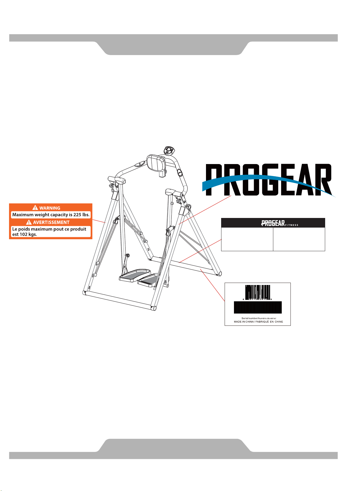
LABELPLACEMENT
For customer assistance call:
1-844-641-7920
8 am - 5 pm PST
Daily
Pour le service a la clientèle
composer le:
1-844-641-7920
Tous les jours
8:00 h - 17 h (HNP)
114711341000001
3
Page 6

Basic precautions should always be followed, including the following safety
instructions when using this equipment. Read all instructions before using this
equipment.
1. Before exercising and to avoid injuring your muscles, it is highly recommended
that you perform warm-up exercises for each muscle group. Please refer to
Warm Up section of the Owner’s Manual.
2. Please make sure all components are not damaged and are working order
before using. This equipment should be placed on a stable, flat surface. Using a
mat or similar material on the ground is recommended.
3. Please wear proper clothes and shoes when using this equipment. Do not
wear loose clothing that may get caught by any part of the equipment.
4. Only perform maintenance or adjustments that are instructed in this manual.
Should any problems arise, discontinue use and consult with customer service
at Paradigm.
5. Be careful when stepping on or stepping off the pedals. Always hold onto the
handlebars first and make sure the pedal at your side is at its lowest position,
then step on. With your other leg, stride over the main frame and come to rest
onto the other pedal. To ensure the pedals run smoothly, push or pull on the
handlebars first, then follow with leg motion. To dismount, reduce pedaling
speed gradually before you stop. When stepping off the machine, make sure
one pedal is at its lowest position and step out of there before stepping out of
the pedal at the highest position.
6. Keep dry - do not operate in wet or moist condition.
7. Do not use the equipment outdoors.
8. This equipment is for household use only.
9. Only one person should be on the equipment at a time.
10. Keep children and pets away from the product at all times.
11. This machine is designed for adults only.
12. This product requires a minimum of 6 feet of space for safe operation.
13. If you feel any chest pains, nausea, dizziness, or short of breath, you should
stop exercising immediately and consult with your physician before continuing.
14. The maximum weight capacity for this product is 225 lbs / 102 kgs.
IMPORTANTSAFETYINSTRUCTIONS
WARNING: Before beginning any exercise program consult your physician.
This is especially important for the people who are over 35 years old or who have
pre-existing health problems.
CAUTION: Read all instructions carefully before operating this product.
Retain this Owner’s Manual for future reference.
4
Page 7
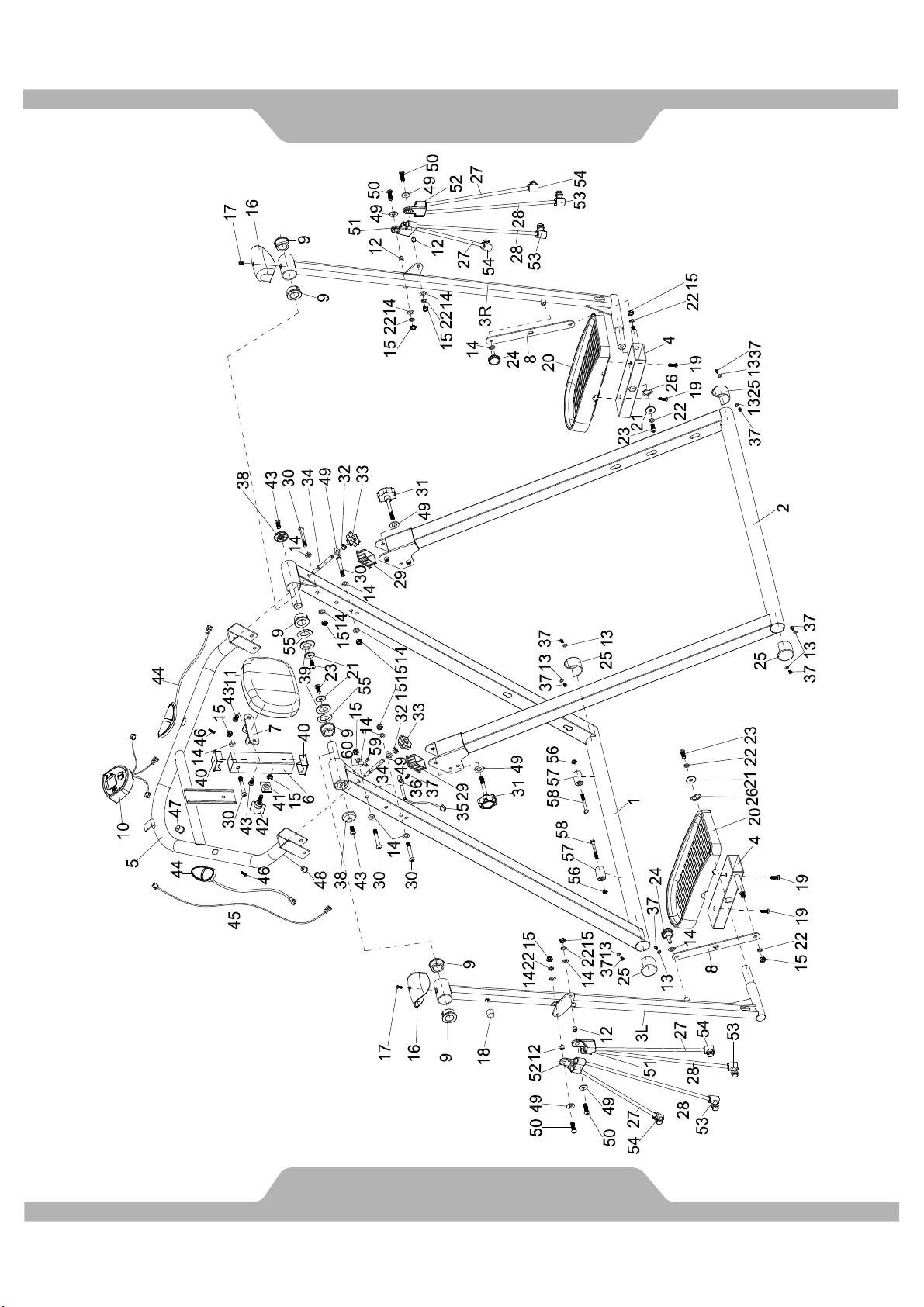
OVERVIEWDRAWING
5
Page 8
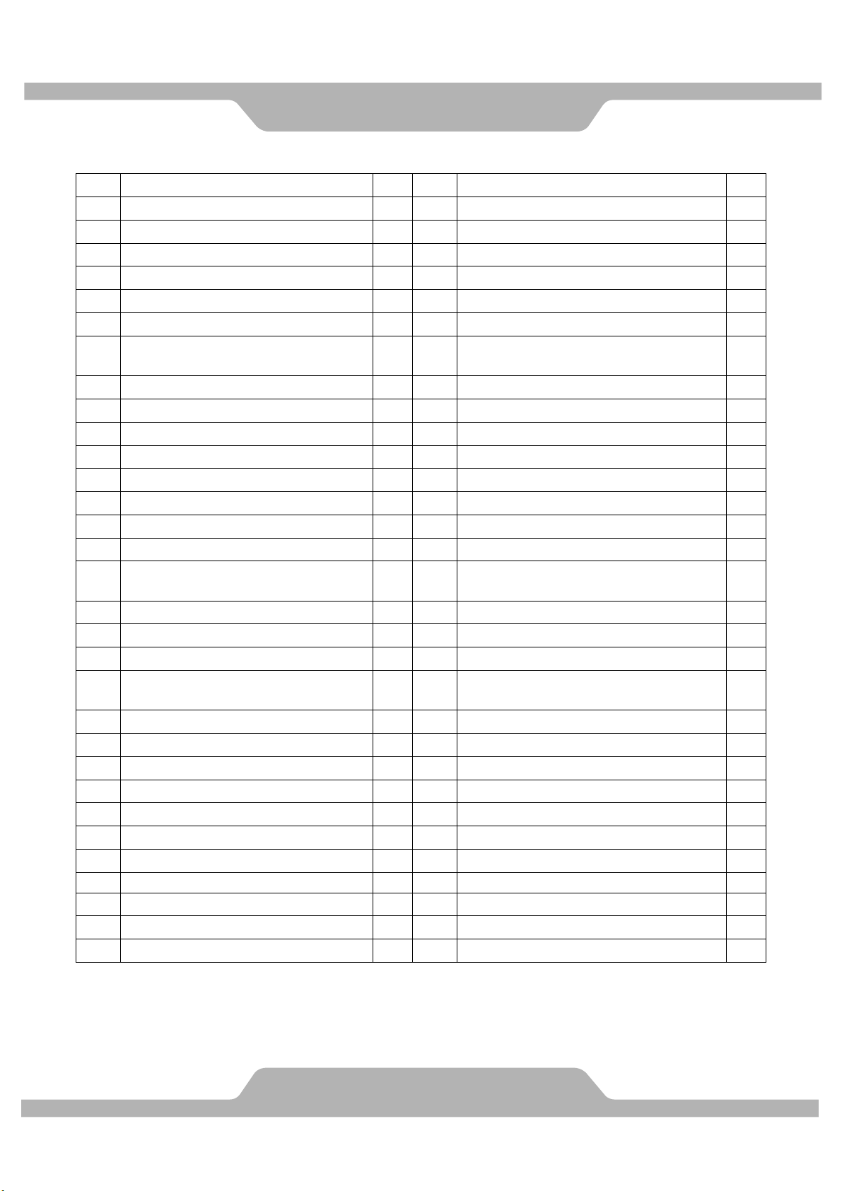
No. Description Qty No. Description Qty
1 Front Stabilizer 1 31 Lock Pin M8x55 2
2 Rear Stabilizer 1 32 Hex Nut M8x6.8 2
3L Swing Post (L) 1 33 Knob 2
3R Swing Post (R) 1 34 Locking Rod 2
4 Pedal Tube 2 35 Sensor 1
5 Handlebar 1 36 Sensor Holder 1
6 Cushion Support Tube 1 37
7 Pad Bracket 1 38 Cap 2
8 Pedal Fixed Plate 2 39 Washer φ38xφ8.2x2 2
9 Bushing 6 40 Cap 2
10 Console 1 41 Lock Plate 1
11 Cushion/Pad 1 42 Round Knob M8x28,φ40 1
12 Bushing 4 43 Socket Hex Screw M8x15, S5 4
13 Washer φ10xφ5x1 8 44 Hand Pulse 2
14 Flat Washerφ16xφ8.2x1.5 15 45 Sensor Wire 650mm 1
15 Nylon Nut M8 12 46
16 Handlebar Cover 2 47 Bushing φ15 1
17 Phillips Pan Head Screw M4x10 2 48 Bushing φ12 1
18 Magnet 1 49 Flat Washer φ22xφ8.2x1.5 8
Phillips Pan Head Self-tapping
19
Screw ST5.5x22
20 Pedal 2 51 Clip 2
21 Washer φ25xφ8.2x2 4 52 Clip 2
22 Spring WasherD8 8 53 Long Buckle 4
23 Socket Hex Screw M8x20 4 54 Short Buckle 4
24 Knob M8x25 2 55 Wave Washer φ38xφ22.5 2
25 Foot Cap 4 56 Nylon Nut M6 2
26 Wave Washer 2 57 Bearing 2
27 Nylon Rope φ8x300mm 4 58 Hex Bolt M6x48 2
28 Nylon Rope φ8x400mm 4 59 Phillips Pan Head Screw M4x10 1
29 End Cap 2 60 Clip 1
30 Socket Hex Screw M8x55x15 5
PARTLIST
Phillips Pan Head Self-Tapping
Screw ST4.2x13
Phillips Pan Head Self-tapping
Screw ST4.2x19
4 50 Socket Hex Bolt M8x25 4
9
2
6
Page 9
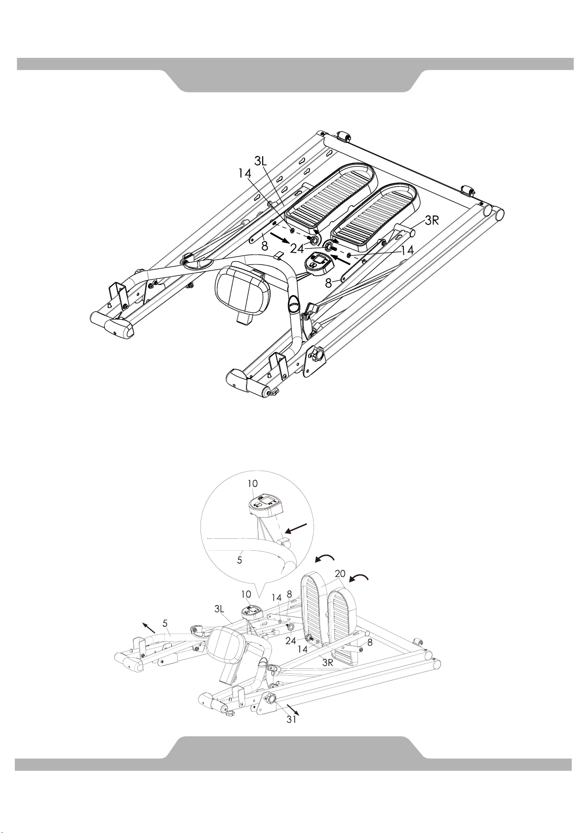
ASSEMBLY
1. Remove both Flat Washers (14) and Knobs (24) from Swing Posts (3L & 3R).
2A. Attach Console (10) onto the metal plate on Handlebar (5), see Pic. A.
2B. Place Pedals (20) vertically and align the top holes on Pedal Fixed Plates (8) with
Swing Posts (3L & 3R), Use Flat Washers (14) and Knobs (24) from Step 1 to secure
Pedals (20). Loosen the Lock Pin (31) from the main frame.
A
7
Page 10
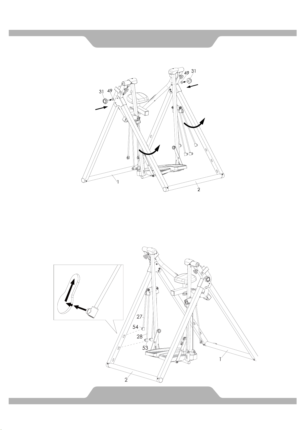
3. Place the unit in upright position; use Lock Pins (31) to secure the joining plates of Front and
Rear Stabilizers (1 & 2).
4. Extend Nylon Rope (27) and insert Short Buckle (54) into the top hole on Rear Stabilizer (2).
Repeat the same steps for Nylon Rope (28) and Long Buckle (53).
Once the steps are completed, repeat for the right side and both sides of Front Stabilizer (1).
Caution
To prevent any injury, please use both hands when extending Nylon Ropes (27 & 28).
Do make sure buckles are locked, see Pic. A.
A
ASSEMBLY
8
Page 11
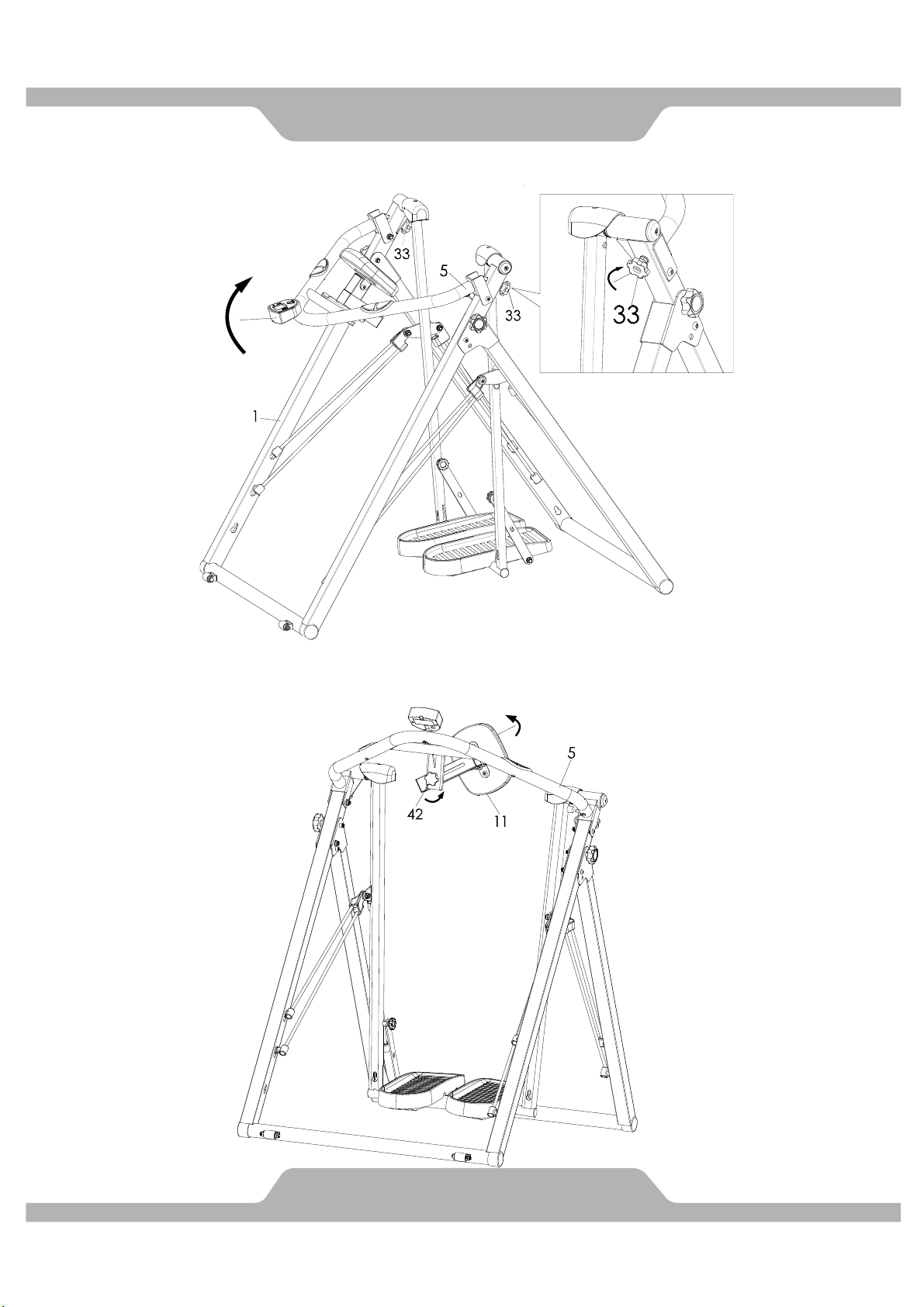
ASSEMBLY
5. Pull up Handlebar (5) and tighten Knobs (33).
6A. Loosen Round Knob (42) until Cushion (11) is adjustable.
Align the supporting plates and tighten Round Knob (42).
9
Page 12
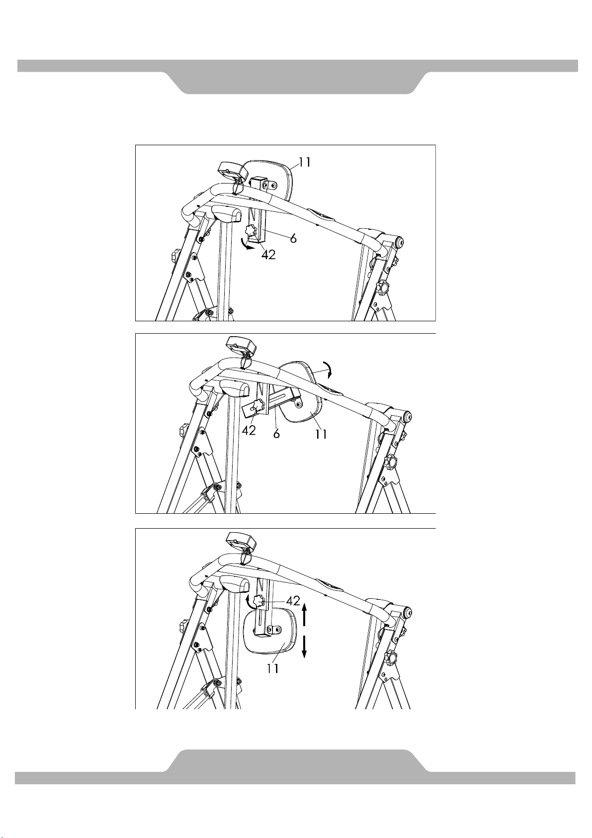
ASSEMBLY
6B. To ensure Cushion (11) is at the desired location, some adjustments may be required.
10
Page 13
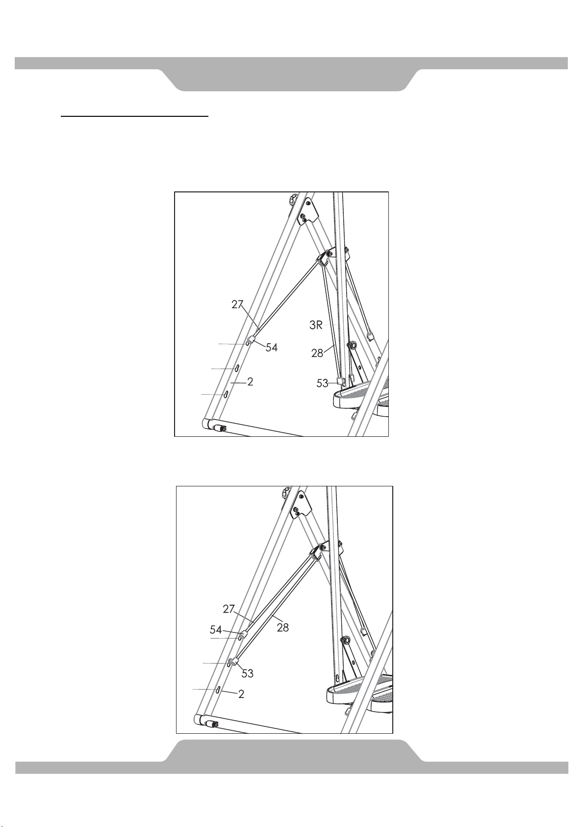
Suggested Tension Levels
Tension Level – Low
Lock Short Buckles (54) in Hole A on all sides.
Lock 2 Long Buckles (53) on Swing Posts (3L & 3R) from Rear Stabilizer (2). Repeat same
step for Front Stabilizer (1).
Tension Level – Medium
Lock Short Buckles (54) in Hole A on all sides.
Lock Long Buckles (53) in Hole B on all sides.
TENSIONADJUSTMENT
A
B
C
A
B
C
11
Page 14
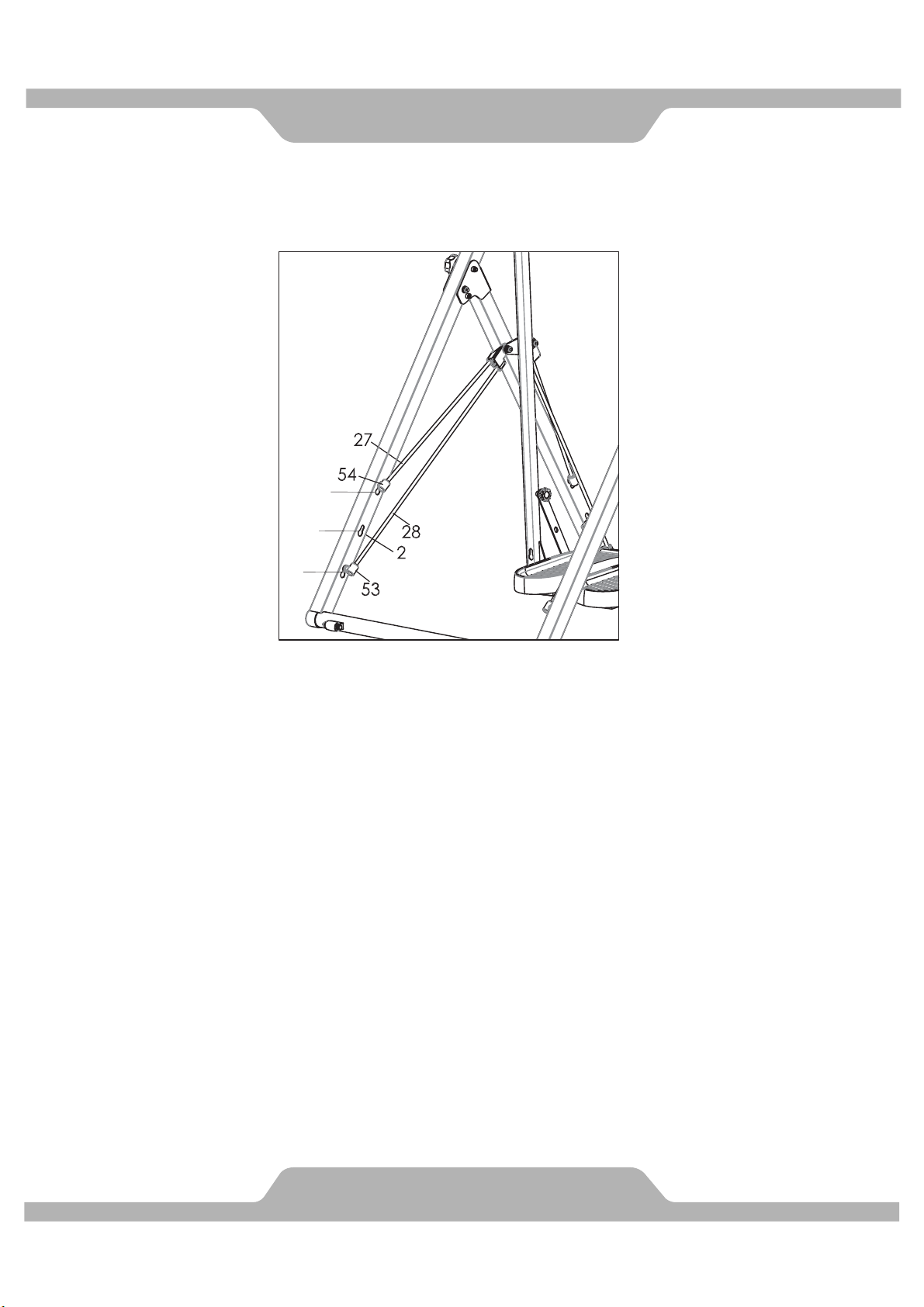
Tension Level – High
Lock Short Buckles (54) in Hole A on all sides.
Lock Long Buckles (53) in Hole C on all sides.
TENSIONADJUSTMENT
A
B
C
12
Page 15
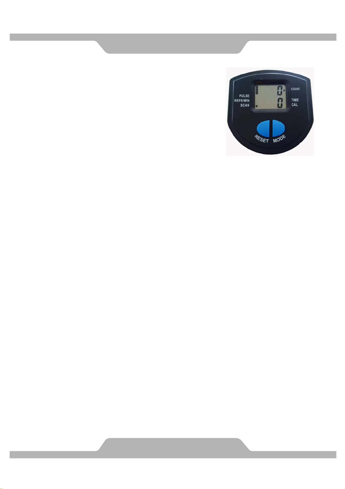
SPECIFICATIONS:
TIME ------------------------------------------------ 00:00-99:59 MIN
STRIDES/MIN------------------------------------- 0~9999
TOTAL STRIDES--------------------------------- 0.0~9999
CALORIES ---------------------------------------- 0.0~9999 KCAL
PULSE ---------------------------------------------- 40-200 BPM
KEY FUNTIONS:
MODE: This key lets you to select and lock on to a particular function you want.
RESET: The monitor will be reset by changing battery or by pressing and holding the
RESET key for 3~4 seconds.
FUNCTIONS:
1. TIME: Press the MODE key until pointer lock on to TIME.
The total working time will be shown when starting exercise.
2. SPEED: Press the MODE key until pointer lock on to REPS/MIN.
Display current speed during workout time.
3. TOTAL STRIDES: Automatically accumulates workout count when starting exercise.
4. CALORIES: Press the MODE key until pointer lock on to CALORIES.
The calories burned will be displayed when starting exercise.
5. PULSE: Press the MODE key until pointer advance to PULSE FUNCTION and put
your hands to hold the sensor about 3 seconds until show out.
AUTO SCAN: Display changes according to the next diagram every 4 seconds.
Automatically display of the following functions in the order shown:
TIME-CALORIE-STRIDES/MIN-PULSE
NOTE:
1. Without any signal coming in 4-5 minutes, the LCD display will be shut off
automatically.
2. When there is signal input, the monitor automatically turns on.
3. If there is a possibility to see an improper display on the Monitor, please
replace the batteries to have a good result.
4. The monitor use 2pcs of 1.5V “AAA” battery.
COMPUTER
13
Page 16
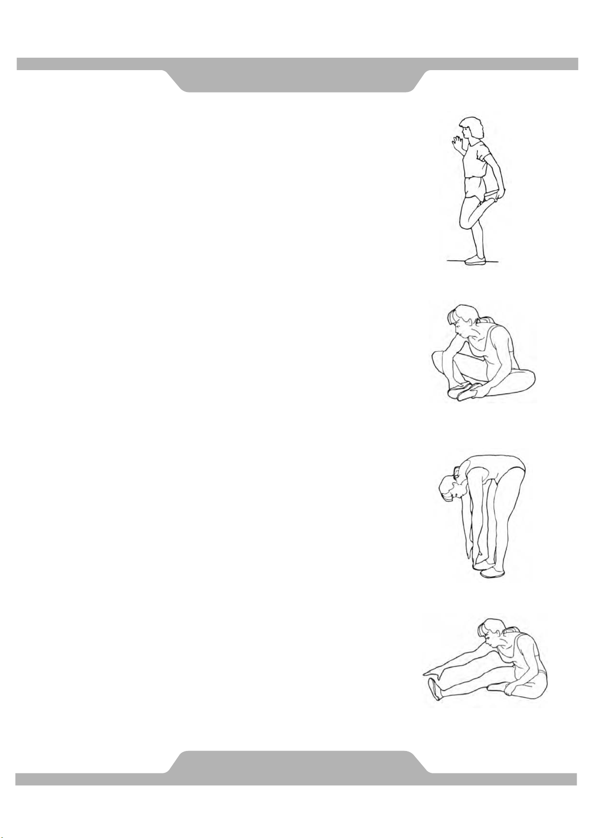
Quadriceps Stretch
With one hand against a wall for balance, reach behind
you and pull your right foot up. Bring your heel as close
to your buttocks as possible. Hold for 15 counts and
repeat with left foot up.
Inner Thigh Stretch
Sit with the soles of your feet together with your knees
pointing outward. Pull your feet as close to your groin
as possible. Gently push your knees towards the floor.
Hold for 15 counts.
Toe Touching
Slowly bend forward from your waist, letting you back and
shoulders relax as you stretch toward your toes. Reach
down as far as you can and hold for 15 counts.
Hamstring Stretch
Sit with your right leg extended. Rest the sole of your left
foot against your right inner thigh. Stretch toward your
toe as far as possible. Relax and hold for 15 counts.
Repeat with left leg extended.
WARMUP
14
Page 17

WARRANTY
MANUFACTURER’S LIMITED WARRANTY
Paradigm Health & Wellness warrants to the original purchaser that this product is free from defects in
material and workmanship when used for the purpose intended, under the conditions that it has been
installed and operated in accordance with Paradigm’s Owner’s Manual. Paradigm’s obligation under this
warranty applies to the following:
COMPONENT LENGTH OF WARRANTY
Structural Frame 1 year
All Other Components 90 days
(computer display, electronics, upholstery, foam, ball bearings, pulleys, belts, cables, wires, shocks, covers,
tension, internal mechanism, wheels, pedals, knobs, accessories and hardware)
Exclusions from Warranty Coverage:
Paradigm does not warrant against and is not responsible for, and no implied warranty shall be deemed to
cover, any product failure, product malfunction, or damages attributable to:
1. Improper installation and/or failure to abide by Paradigm’s installation guidelines;
2. Use of this product beyond normal home use, or in an application for which it was not designed;
3. Cosmetic items such as scratches, dents or discolorations;
4. Damage caused by normal wear and tear, vandalism, accidental or by animals;
5. Any act of Nature (such as fire, flooding, snow, ice, hurricane, earthquake, lightning or other natural
disaster), environmental condition (such as air pollution, mold, mildew, etc.), or staining from foreign
substances (such as dirt, grease, oil, etc.);
6. Normal weathering due to exposure to sunlight, weather and atmosphere which can cause colored
surfaces to, among other things, flake, chalk, accumulate dirt or stains.
7. Improper operation, alteration, handling, storage, abuse or neglect of the products.
Paradigm, using its sole discretion, will either repair or replace free of charge any part(s) proven to be
defective under normal home use. Any repair or replacement shall provide no new warranty coverage, but
shall retain only the remaining portion of the original product’s warranty. This warranty is offered only to the
original purchaser and is not transferable. Proof of original purchase is required.
Ordering Replacement Parts
Replacement parts can be ordered by calling or emailing our customer service department:
1-844-641-7920
Daily 8:00 AM - 5:00 PM (PST).
When ordering replacement parts please have the following information ready:
1. Owner’s Manual
2. Model Number
3. Description of Parts
4. Part Number
5. Date of Purchase
15
Page 18
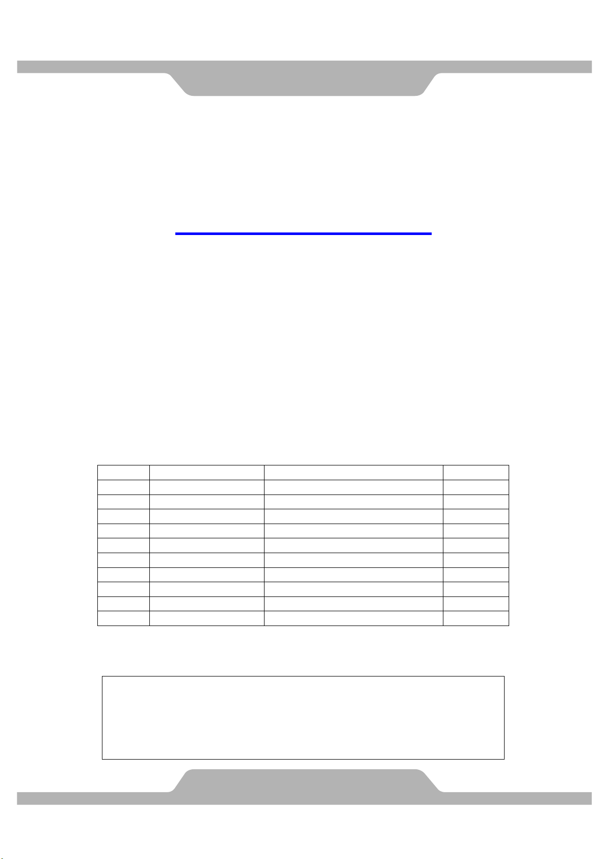
FAXFORM
Paradigm Health & Wellness, Inc.
PARTS REQUEST FAX FORM
Please fax this form to (1-626-810-2166)
OR YOU CAN EMAIL CUSTOMER SERVICE REQUESTS TO
NAME: _______________________________________________________
ADDRESS: ____________________________________________________
CITY ______________ STATE ______________ ZIP ___________________
TELEPHONE: (Day) _____________________________________________
(Night) ____________________________________________
(Email Address) ____________________________________
SERIAL#: __________________________________________
ITEM/MODEL#: _____________________________________
PURCHASE DATE: ______________________________________________
PURCHASE FROM: _____________________________________________
PART # DESCRIPTION REASON QTY
“YOUR ORDER WILL BE PROCESSED WITHIN 3 BUSINESS DAYS”
OFFICIAL USE ONLY (MD)
SHIP DAT E: ___________________________________________
TRK #: _______________________________________________
BACK ORDER: ________________________________________
16
 Loading...