

Page 1
Part No. 204439 R0903A Printed in China © 2003 ICON Health & Fitness, Inc.
ORDERING REPLACEMENT PARTS
If you encounter any difficulties with this product, or if you need to order replacement parts, please call or write
the ICON Health & Fitness, Ltd. office.
ICON Health & Fitness, Ltd.
Unit 4
Revie Road Industrial Estate
Revie Road
Beeston
Leeds, LS118JG
UK
Tel: Country Code:
Outside the UK: 0 (444) 113 387 7133
Fax: 0 (444) 113-387 7125
When calling or writing, please provide the following information:
• The MODEL NUMBER of the product (PFEVRW39930)
• The NAME of the product (PROFORM
®
R400 rowing machine)
• The KEY NUMBER and DESCRIPTION of the part(s) (see the PART LIST and the EXPLODED DRAWING on
pages 10 and 11)
08457 089 009
Model No. PFEVRW39930
www.iconeurope.com
Visit our website at
QUESTIONS?
As a manufacturer, we are committed to providing complete
customer satisfaction. If you
have questions, or if there are
missing or damaged parts,
please call:
Or write:
ICON Health & Fitness, Ltd.
Unit 4
Revie Road Industrial Estate
Revie Road
Beeston
Leeds, LS11 8JG
UK
email: csuk@iconeurope.com
08457 089 009
CAUTION
Read all precautions and instructions in this manual before using
this equipment. Save this manual
for future reference.
USER’S MANUAL
Class HC Fitness Product
Page 2
11
2
PROFORM is a registered trademark of ICON Health & Fitness, Inc.
70
70
69
69
26
26
26
26
73
73
73
68
68
85
79
1
29
3
2
4
4
4
4
37
37
28
56
71
7
27
24
24
24
24
5
5
22
22
23
23
18
19
78
20
47
32
46
48
50
42
82
75
75
58
58
59
60
12
63
63
6
6
64
64
61
65
65
66
66
39
35
35
36
36
40
40
41
72
83 11
33
33
30
30
13
13
13
14
14
15
17
16
17
16
21
22
5
5
33
33
34
5
6
43
74
31
10
62
57
34
84
6
5
44
45
45
86
81
9
9
25
25
92
80
87
77
91
55
55
55
52
52
89
89
51
51
51
67
39
38
26
26
55
55
8
24
51
24
54
53
55
90
90
88
86
49
86
93
94
95
95
95
EXPLODED DRAWING—Model No. PFEVRW39930 R0903A
TABLE OF CONTENTS
IMPORTANT PRECAUTIONS . . . . . . . . . . . . . . . . . . . . . . . . . . . . . . . . . . . . . . . . . . . . . . . . . . . . . . . . . . . . .2
BEFORE YOU BEGIN . . . . . . . . . . . . . . . . . . . . . . . . . . . . . . . . . . . . . . . . . . . . . . . . . . . . . . . . . . . . . . . . . . .3
ASSEMBLY . . . . . . . . . . . . . . . . . . . . . . . . . . . . . . . . . . . . . . . . . . . . . . . . . . . . . . . . . . . . . . . . . . . . . . . . . . .4
HOW TO USE THE ROWING MACHINE . . . . . . . . . . . . . . . . . . . . . . . . . . . . . . . . . . . . . . . . . . . . . . . . . . . . .7
MAINTENANCE AND STORAGE . . . . . . . . . . . . . . . . . . . . . . . . . . . . . . . . . . . . . . . . . . . . . . . . . . . . . . . . . . .8
CONDITIONING GUIDELINES . . . . . . . . . . . . . . . . . . . . . . . . . . . . . . . . . . . . . . . . . . . . . . . . . . . . . . . . . . . . .9
PART LIST . . . . . . . . . . . . . . . . . . . . . . . . . . . . . . . . . . . . . . . . . . . . . . . . . . . . . . . . . . . . . . . . . . . . . . . . . . .10
EXPLODED DRAWING . . . . . . . . . . . . . . . . . . . . . . . . . . . . . . . . . . . . . . . . . . . . . . . . . . . . . . . . . . . . . . . . .11
HOW TO ORDER REPLACEMENT PARTS . . . . . . . . . . . . . . . . . . . . . . . . . . . . . . . . . . . . . . . . . . .Back Cover
1. Read all instructions in this manual before
using the rowing machine. Use the rowing
machine only as described.
2. It is the responsibility of the owner to ensure
that all users of the rowing machine are adequately informed of all warnings.
3. Place the rowing machine on a level surface,
with a mat beneath it to protect the floor or
carpet. Keep the rowing machine indoors,
away from moisture and dust.
4. Inspect and properly tighten all parts of the
rowing machine regularly. Replace worn
parts immediately.
5. The rowing machine should not be used by
persons weighing more than 115 kg (250
lbs.).
6. Keep children under 12 and pets away from
the rowing machine at all times.
7. Wear appropriate clothes and athletic shoes
when using the rowing machine.
8. Keep your hands away from moving parts.
9. If you experience dizziness or pain whilst
exercising, stop immediately and cool down.
10. The rowing machine is intended for in-home
use only. Do not use the rowing machine in a
commercial, rental, or institutional setting.
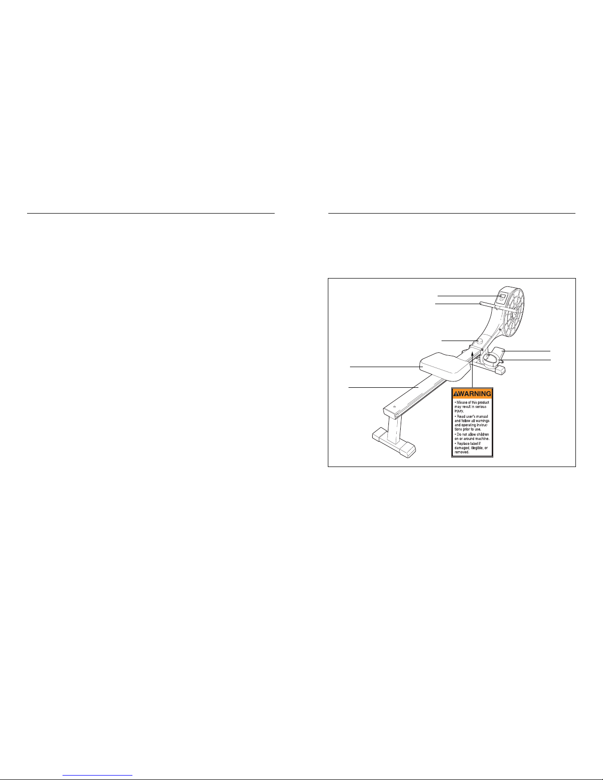
11. A warning decal is found on the rowing
machine in the location shown on page 3. If
the decal is missing or illegible, call 08457
089 009 and order a free replacement decal.
Apply the decal in the location shown.
WARNING:Before beginning this or any exercise program, consult your physician. This
is especially important for persons over the age of 35 or persons with pre-existing health problems.
Read all instructions before using. ICON assumes no responsibility for personal injury or property
damage sustained by or through the use of this product.
IMPORTANT PRECAUTIONS
WARNING:To reduce the risk of serious injury, read the following important precautions
before using the rowing machine.
Page 3
310
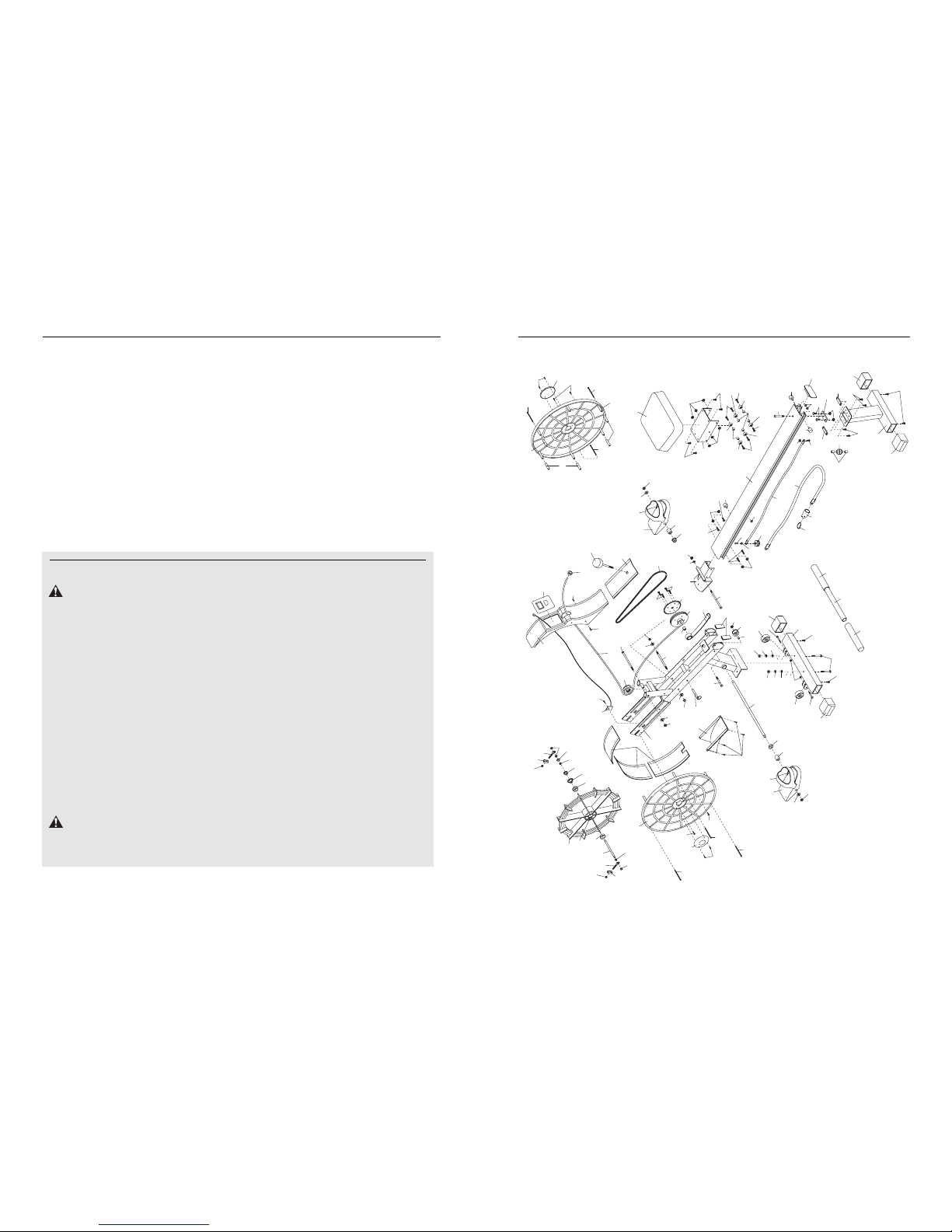
PART LIST—Model No. PFEVRW39930 R0903A
Note: "#" indicates a non-illustrated part. Specifications are subject to change without notice. See the back cover
of this manual for information about ordering replacement parts.
Key
No. Qty. Description
Key
No. Qty. Description
1 1 Frame
2 1 Front Stabiliser
3 1 Rear Stabiliser
4 4 Stabiliser Endcap
5 12 M8 Nylon Locknut
6 4 M8 Washer
7 1 Rail Knob
8 1 Guide Bracket
9 2 Adjustment Bracket
10 1 11mm Spacer
11 1 Cord Wheel
12 1 Rail Endcap
13 3 Stop
14 3 M8 Nut
15 1 M8 x 60mm Button Bolt
16 3 M8 Nylon Locknut
17 3 M8 x 12mm Phillips Screw
18 1 Storage Cord
19 1 Elastic Cord
20 1 Hook
21 1 M6 Nut
22 5 M6 x 20mm Screw
23 6 12mm x 6mm Spacer
24 6 Seat Wheel
25 6 Nylon Nut
26 6 M5 x 75mm Screw
27 1 Seat Carriage
28 1 Seat
29 1 Rail
30 2 Stabiliser Bracket
31 1 M10 Nylon Locknut
32 1 Rail Bracket
33 7 M8 x 15mm Button Screw
34 2 M8 x 135mm Button Bolt
35 2 3/8” Nylon Locknut
36 2 3/8” Washer
37 2 Pedal
38 1 Bottom Cover
39 2 28mm Spacer
40 2 Pedal Spacer
41 1 Storage Pin
42 1 Pedal Axle
43 2 Bushing
44 1 Pulley Axle
45 4 M6 x 30mm Screw
46 1 Large Sprocket
47 1 Chain
48 1 Pulley
49 1 Small Spacer
50 1 Rowing Strap
51 6 M8 x 27mm Button Bolt
52 2 3/8” Cap Nut
53 2 Frame Cap
54 1 Storage Cord Knob
55 7 Phillips Screw
56 1 Frame Cover
57 4 M4 x 15mm Screw
58 2 Foam Grip
59 1 Handle
60 2 M8 x 55mm Carriage Bolt
61 2 M5 Nylon Locknut
62 1 M10 x 55mm Button Bolt
63 2 Stabiliser Wheel
64 2 M5 x 35mm Button Bolt
65 2 M8 Split Washer
66 2 M8 Cap Nut
67 1 Top Cover
68 4 M4 x 16mm Screw
69 2 Fan Cover Cap
70 2 Fan Cover
71 1 Console
72 1 Reed Switch With Wire
73 5 43mm Plastic Spacer
74 1 Rowing Strap Wheel
75 2 Adjustment Bolt
76 1 7mm Spacer
77 1 Magnet
78 1 Cord Cover
79 1 Fan Wheel
80 1 Fan Wheel Bushing
81 1 Bushing With Sprocket
82 1 Fan Wheel Axle
83 2 20mm Spacer
84 1 Guide Wheel
85 3 Fan Cover Panel
86 4 3/8” Nut
87 1 10mm Bushing
88 1 M8 x 20mm Button Screw
89 2 3/8” Flat Washer
90 2 Pedal Strap
91 1 Small Bushing
92 1 3/8” Jam Nut
93 1 Rowing Cord
94 1 Grommet
95 4 M4 x 12mm Screw
# 1 User’s Manual
# 1 Hex Key
BEFORE YOU BEGIN
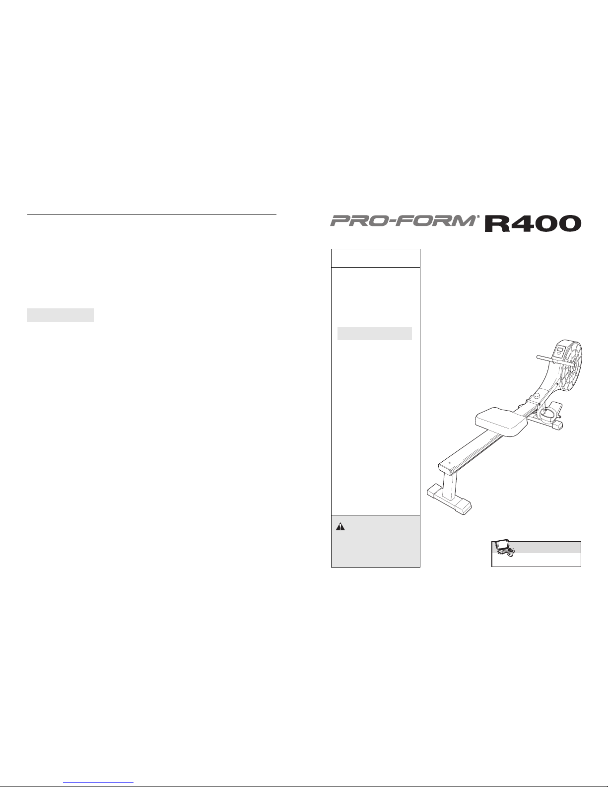
Thank you for purchasing the new PROFORM®R400
rowing machine. Rowing is one of the most effective
exercises known for toning the body, strengthening the
muscles, and building the cardiovascular system. The
R400 rowing machine is designed to let you enjoy this
effective exercise in the convenience of your home.
For your safety and benefit, read this manual carefully before using the rowing machine. If you have
questions after reading this manual, please call our
Customer Service Department at 08457 089 009. To
help us assist you, note the product model number
before calling. The model number is PFEVRW39930.
Console
Pedal
Strap
Handle
Rail Knob
Seat
Rail
Page 4

4 9
1.
Orient the Front Stabiliser (2) so the Stabiliser Wheels
(63) are on the indicated side. Attach the Front
Stabiliser to the Frame (1) with two M8 x 55mm
Carriage Bolts (60), two M8 Washers (6), two M8 Split
Washers (65), and two M8 Cap Nuts (66).
1
66
65
63
63
6
2
60
1
ASSEMBLY
Assembly requires two persons. Place all parts of the rowing machine in a cleared area and remove the packing
materials. Do not dispose of the packing materials until assembly is completed. Read all steps carefully before
beginning.
Assembly requires the included hex key and your own adjustable spanner .
Use the drawings below to identify the small parts used in assembly. The number in parentheses below
each drawing is the key number of the part, from the PART LIST on page 10. The number following the key
number is the quantity needed for assembly. Note: Some small parts may have been pre-attached for ship-
ping. If a part is not in the parts bag, check to see if it has been preattached.
M8 Washer (6)–3
M8 Split Washer (65)–2
M8 Cap Nut
(66)–2
M8 Nylon Locknut (5)–1
M8 x 55mm Carriage Bolt (60)–2
M8 x 15mm Button
Screw (33)–4
M8 x 135mm Button Bolt (34)–1
3/8" Washer (36)–2
3/8" Nylon Locknut (35)–2
M8 Nut (14)–2
The following guidelines will help you to plan your
exercise program. Remember that proper nutrition and
adequate rest are essential for successful results.
EXERCISE INTENSITY
Whether your goal is to burn fat or to strengthen your
cardiovascular system, the key to achieving the
desired results is to exercise with the proper intensity.
The proper intensity level can be found by using your
heart rate as a guide. The chart below shows recommended heart rates for fat burning, maximum fat burning, and cardiovascular (aerobic) exercise.
To find the proper heart rate for you, first find your age
at the bottom of the chart (ages are rounded off to the
nearest ten years). Next, find the three numbers
above your age. The three numbers are your “training
zone.” The lower two numbers are recommended
heart rates for fat burning, and the highest number is
the recommended heart rate for aerobic exercise.
Fat Burning
To burn fat effectively, you must exercise at a relatively low intensity level for a sustained period of time.
During the first few minutes of exercise, your body
uses easily accessible carbohydrate calories for ener-
gy. Only after the first few minutes of exercise does
your body begin to use stored fat calories for energy. If
your goal is to burn fat, adjust the intensity of your
exercise so your heart rate is in the lower half of your
training zone as you exercise.
Aerobic Exercise
If your goal is to strengthen your cardiovascular system, your exercise must be “aerobic.” Aerobic exercise
is activity that requires large amounts of oxygen for
prolonged periods of time. This increases the demand
on the heart to pump blood to the muscles, and on the
lungs to oxygenate the blood. For aerobic exercise,
adjust the intensity of your exercise until your heart
rate is near the highest number in your training zone
as you exercise.
HOW TO MEASURE YOUR HEART RATE
To measure your heart
rate, stop exercising and
place two fingers on
your wrist as shown.
Take a six-second heartbeat count, and multiply
the result by 10 to find
your heart rate. For
example, if your six-second heartbeat count is 13, your heart rate is 130 beats
per minute. (A six-second count is used because your
heart rate will drop rapidly when you stop exercising.)
WORKOUT GUIDELINES
Each workout should include the following three parts:
A warm-up, consisting of 5 to 10 minutes of stretching
and light exercise. A proper warm-up increases your
body temperature, heart rate, and circulation in preparation for exercise.
Training zone exercise, consisting of 20 to 30 minutes of exercising with your heart rate in your training
zone. Note: During the first few weeks of your exercise program, do not keep your heart rate in your
training zone for longer than 20 minutes.
A cool-down, with 5 to 10 minutes of stretching. This
will increase the flexibility of your muscles and will
help to prevent post-exercise problems.
EXERCISE FREQUENCY
To maintain or improve your condition, plan three workouts each week, with at least one day of rest between
workouts. After a few months of regular exercise, you
may complete up to five workouts each week if
desired. The key to success is make exercise a regular and enjoyable part of your everyday life.
CONDITIONING GUIDELINES
WARNING:Before beginning this
or any exercise program, consult your physician. This is especially important for individuals over the age of 35 or individuals with preexisting health problems.
Page 5
5
8
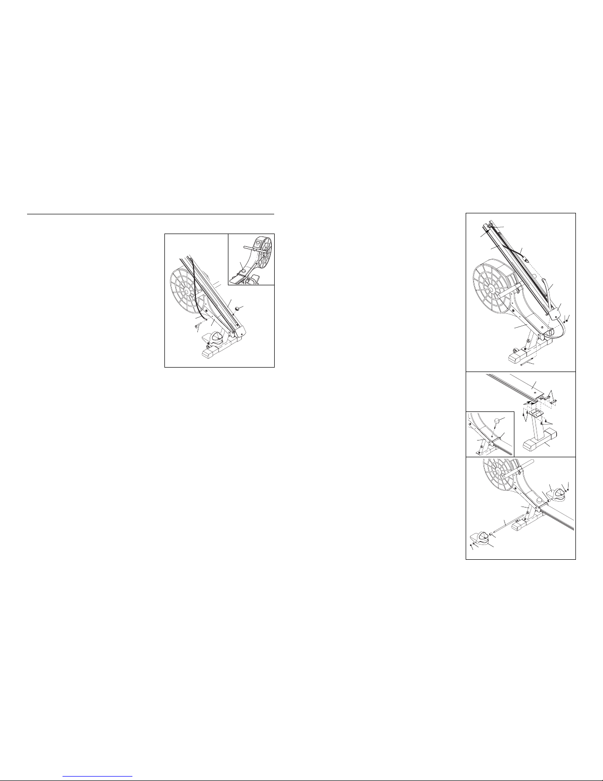
3. Slide the two Stabiliser Brackets (30) into the end of
the Rail (29). Align the holes in the Stabiliser
Brackets with the indicated holes in the bottom of
the Rail. Attach the Rear Stabiliser (3) to the Rail
and the Stabiliser Brackets with four M8 x 15mm
Button Screws (33).
See the inset drawing. Insert the Rail Knob (7) into
the Frame (1), and tighten the Rail Knob into the
Rail Bracket (32).
4. Insert the Pedal Axle (42) into the Frame (1). Slide
a 28mm Spacer (39), a Pedal (37), and a 3/8”
Washer (36) onto each end of the Pedal Axle.
Tighten a 3/8” Nylon Locknut (35) onto each end of
the Pedal Axle.
33
33
3
30
Holes
7
29
32
1
37
39
36
35
35
36 37
39
42
1
3
4
2. Have another person hold the Rail (29) in the position shown. Attach the Rail Bracket (32) to the
Frame (1) with an M8 x 135mm Button Bolt (34), an
M8 Washer (6), and an M8 Nylon Locknut (5).
Route the Rowing Strap (50) through the Rail
Bracket (32) as shown. Unhook the Elastic Cord
(19) from the indicated hole in the Rail (29). Make
sure that the Elastic Cord is routed around the Cord
Wheel (11), and connect the Elastic Cord to the
Rowing Strap.
29
Hole
11
19
50
32
34
1
6
5
2
MAINTENANCE AND STORAGE
Inspect and tighten all parts of the rowing machine
regularly. Replace any worn parts immediately.
To keep the rowing machine free from dust and dirt,
periodically wipe the rail, the seat wheels, and other
parts with a soft cloth and mild detergent. To prevent
damage to the console, keep liquids away from the console and keep the console out of direct sunlight.
If the console does not function properly, replace the
batteries. See assembly step 5 on page 6 for battery
installation instructions.
When the rowing machine is not in use, it can be folded
to conserve space. See the inset drawing. Remove the
Rail Knob (7). Next, fold the Rail (29) to the position
shown. Remove the Storage Cord Knob (54), and
secure the end of the Storage Cord (18) to the Frame
(1) with the Storage Pin (41) as shown. Thread the
Storage Cord Knob back onto the Rail.
Remove the batteries from the console when storing
the rowing machine for longer than one month.
29
41
1
18
54
7
Page 6

6. Slide the Seat (28) onto the Rail (29). Attach two
Stops (13) to the Rail with two M8 Nuts (14).
Press the Rail Endcap (12) into the Rail (29).
5. The Console (71) requires two AA 1,5V batteries.
Alkaline batteries are recommended. See the inset
drawing. Insert two batteries into the clip on the
back of the Console; make sure that the negative
ends of the batteries (marked “–”) are touching
the springs in the clip.
Next, plug the Reed Switch Wire (72) into the
Console (71). Press the Console into the Top Cover
(67). Make sure that the Reed Switch Wire is not
pinched between the Console and the Top Cover.
67
72
71
5
14
12
13
13
29
28
7. Make sure that all parts are properly tightened before you use the rowing machine. Place a mat under
the rowing machine to protect the floor or carpet.
Batteries
Clip
71
6
7
HOW TO USE THE ROWING MACHINE
DESCRIPTION OF THE CONSOLE
The console features five modes that provide instant
exercise feedback:
• Speed—This mode displays your rowing speed, in
kilometres per hour. Use the chart below to convert
kilometres per hour to miles per hour.
• Scan—This mode displays the distance, time, and
calorie modes, changing modes every few seconds.
• Distance—This mode displays the total distance that
you have rowed, in kilometres. Use the chart below
to convert kilometres to miles.
• Time—This mode displays the length of time you
have rowed during your workout.
• Calorie—This mode displays the approximate number of calories you have burned.
HOW TO OPERATE THE CONSOLE
To turn on the console, press the console button.
When the console is turned on, the upper half of the
console display will show your rowing speed. The
lower half of the display will show the distance, time,
and calorie modes, changing modes every few seconds. To view the distance, time, or calorie mode continuously, press the console button repeatedly until a
D (distance), a T (time), or a C (calorie) appears in
the lower half of the display; make sure that the scan
indicator (the oval symbol) does not appear. To again
view the distance, time, and calorie modes, press the
console button repeatedly until the scan indicator
appears.
To reset the display, press the console button for a
few seconds.
To turn off the console, simply wait for a few minutes.
If the handle is not pulled and the console button is
not pressed for a few minutes, the power will turn off
automatically to conserve the batteries.
PROPER ROWING FORM
Sit on the seat, facing the pedals. Place your feet in
the pedals and adjust the straps to fit your feet.
Hold the handle with an overhand grip. Correct rowing
form consists of three phases:
1. The first phase is the catch. Slide the seat forward
until your knees are almost touching your chest.
2. The second phase is the drive. Push backward
using your legs. Keep your back straight. Lean
back slightly at the hips (not at the waist) and begin
pulling the handle toward your chest. Keep your
elbows outward.
3. The third phase is the finish. Your legs should be
nearly straight. Continue to pull the handle until
your hands are even with your chest.
After the finish phase, extend your arms forward and
pull the seat forward using your legs. Repeat, moving
through all three phases with a smooth, fluid motion.
Remember to breathe normally as you row—never
hold your breath.
6
 Loading...