

Page 1
www.proform.com
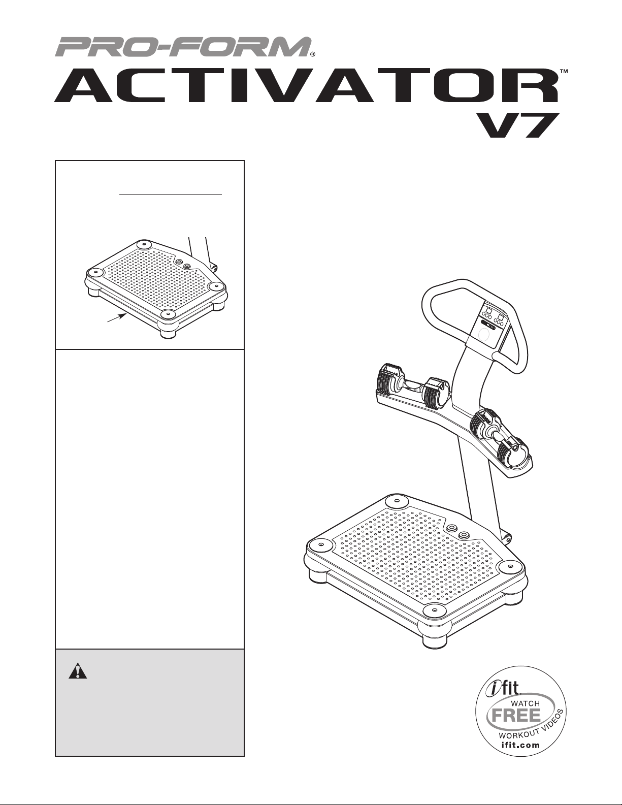
Model No. PFVB14988.0
Serial No.
Write the serial number in the
space above for reference.
Serial
Number
Decal
QUESTIONS?
If you have questions, or if parts are
damaged or missing, PLEASE DO
NOT CONTACT THE STORE;
please contact Customer Care.
USERʼS MANUAL
IMPORTANT: Please register this
product (see the limited warranty
on the back cover of this manual)
before contacting Customer Care.
CALL TOLL-FREE:
1-888-533-1333
Mon.–Fri. 6 a.m.–6 p.m. MT
Sat. 8 a.m.–4 p.m. MT
ON THE WEB:
www.proformservice.com
CAUTION
Read all precautions and instructions in this manual before using
this equipment. Keep this manual
for future reference.
Page 2
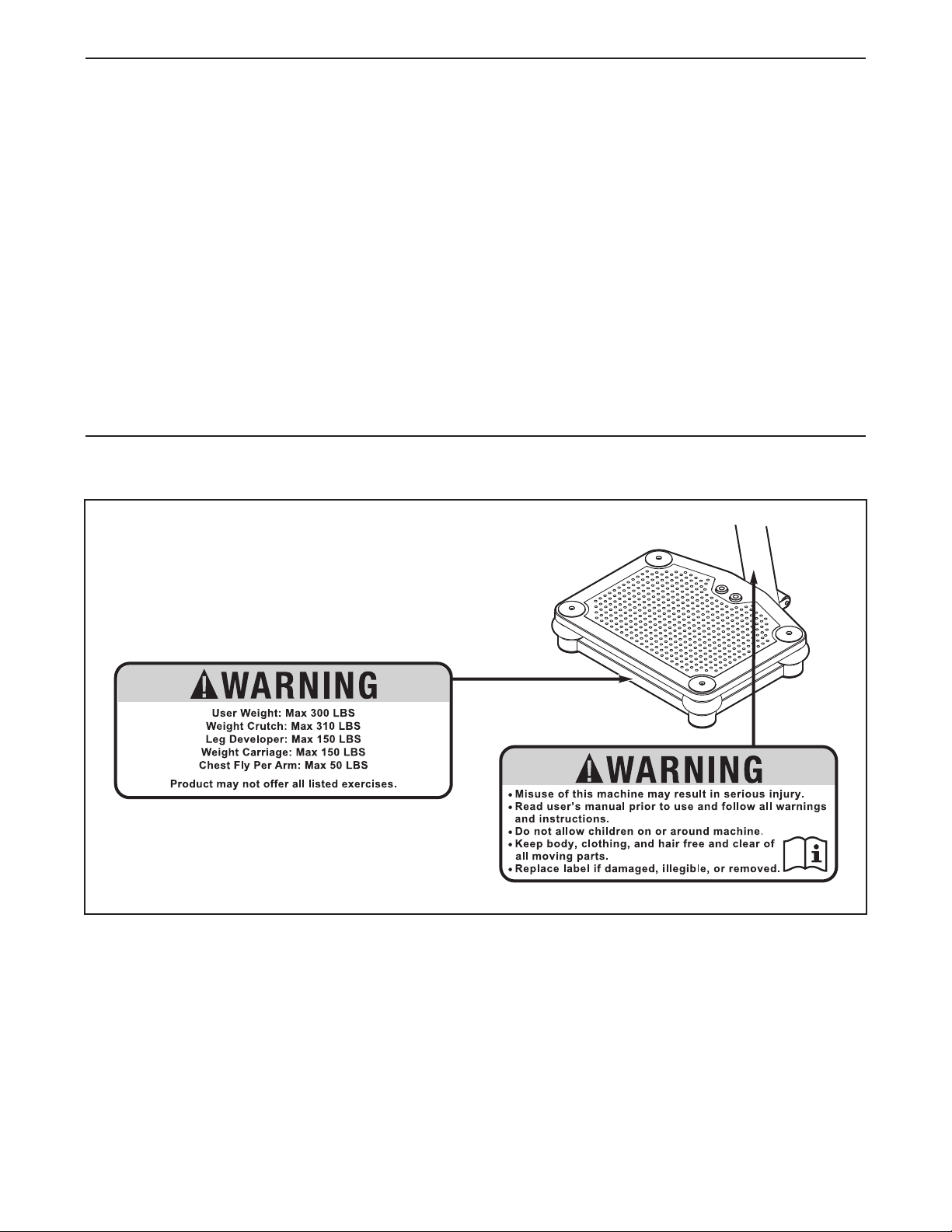
TABLE OF CONTENTS
WARNING DECAL PLACEMENT . . . . . . . . . . . . . . . . . . . . . . . . . . . . . . . . . . . . . . . . . . . . . . . . . . . . . . . . . . . . . .2
MPORTANT PRECAUTIONS . . . . . . . . . . . . . . . . . . . . . . . . . . . . . . . . . . . . . . . . . . . . . . . . . . . . . . . . . . . . . . . .3
I
BEFORE YOU BEGIN . . . . . . . . . . . . . . . . . . . . . . . . . . . . . . . . . . . . . . . . . . . . . . . . . . . . . . . . . . . . . . . . . . . . . .5
PART IDENTIFICATION CHART . . . . . . . . . . . . . . . . . . . . . . . . . . . . . . . . . . . . . . . . . . . . . . . . . . . . . . . . . . . . . .6
ASSEMBLY . . . . . . . . . . . . . . . . . . . . . . . . . . . . . . . . . . . . . . . . . . . . . . . . . . . . . . . . . . . . . . . . . . . . . . . . . . . . . . .7
HOW TO USE THE VIBRATION PLATFORM . . . . . . . . . . . . . . . . . . . . . . . . . . . . . . . . . . . . . . . . . . . . . . . . . . .13
TROUBLESHOOTING . . . . . . . . . . . . . . . . . . . . . . . . . . . . . . . . . . . . . . . . . . . . . . . . . . . . . . . . . . . . . . . . . . . . .17
PART LIST . . . . . . . . . . . . . . . . . . . . . . . . . . . . . . . . . . . . . . . . . . . . . . . . . . . . . . . . . . . . . . . . . . . . . . . . . . . . . .18
EXPLODED DRAWING . . . . . . . . . . . . . . . . . . . . . . . . . . . . . . . . . . . . . . . . . . . . . . . . . . . . . . . . . . . . . . . . . . . .19
ORDERING REPLACEMENT PARTS . . . . . . . . . . . . . . . . . . . . . . . . . . . . . . . . . . . . . . . . . . . . . . . . . .Back Cover
LIMITED WARRANTY . . . . . . . . . . . . . . . . . . . . . . . . . . . . . . . . . . . . . . . . . . . . . . . . . . . . . . . . . . . . . .Back Cover
WARNING DECAL PLACEMENT
The warning decals shown here have been applied in
the locations shown. If a decal is missing or illegible,
see the front cover of this manual and request a
free replacement decal. Apply the decal in the location shown. Note: The decals may not be shown at
actual size.
PROFORM is a registered trademark of ICON IP, Inc.
2
Page 3

IMPORTANT PRECAUTIONS
WARNING: To reduce the risk of serious injury, read all important precautions and
instructions in this manual and all warnings on the vibration platform before using the vibration
platform. ICON assumes no responsibility for personal injury or property damage sustained by or
hrough the use of this product.
t
1. Before beginning any exercise program,
consult your physician. This is especially
important for persons over age 35 or persons with pre-existing health problems.
2. It is the responsibility of the owner to ensure
that all users of the vibration platform are
adequately informed of all precautions.
3. The vibration platform is intended for home
use only. Do not use the vibration platform
in a commercial, rental, or institutional setting.
4. Keep the vibration platform indoors, away
from moisture and dust. Place the vibration
platform on a level surface, with a mat
beneath it to protect the floor or carpet. Do
not place the vibration platform in a garage
or covered patio, or near water.
5. Inspect and properly tighten all parts regularly. Replace any worn parts immediately.
6. Keep children under age 12 and pets away
from the vibration platform at all times.
11. Be careful when stepping down from the
vibration platform; your muscles will feel different after you exercise on the vibration
platform.
12. The following is a list of factors and conditions that may make exercising on the
vibration platform inadvisable (this list is not
exhaustive; it is intended only for reference).
If one or more factors or conditions apply to
you, consult your physician before using the
vibration platform.
• Knee or hip implant
• Pacemaker
• Recently placed screws, pins, bolts, or
spirals
• Acute hernia, discopathy, or spondylitis
• Serious heart or vascular disease
• Acute thrombosis
• Tumor
• Serious migraine
• Epilepsy
• Serious diabetes
• Recent wound due to operation
• Fresh inflammation
• Pregnancy
7. The vibration platform should not be used
by persons weighing more than 300 lbs.
(136 kg).
8. Never allow more than one person on the
vibration platform at a time.
9. Keep your back straight while using the
vibration platform; do not arch your back.
When standing on the vibration platform,
bend your knees slightly and balance your
weight on the balls of your feet.
10. It is recommended that you use the vibration
platform no more than 15 minutes per day
and no more than 3 times per week.
13. Over exercising may result in serious injury
or death. If you feel faint or if you experience
pain while exercising, stop immediately and
cool down.
14. Make sure that the dumbbells are secure in
the weight rests when they are not in use.
15. Always remove the dumbbells from the
vibration platform before moving the vibration platform.
16. Use the vibration platform and the included
dumbbells only as described in this manual.
3
Page 4

17. When connecting the power cord (see page
4), plug the power cord into a surge sup-
1
pressor (not included) and plug the surge
suppressor into a grounded outlet capable
of carrying 15 or more amps. No other appliance should be on the same circuit as the
vibration platform. Do not use an extension
ord.
c
18. Use only a single-outlet surge suppressor
that meets all of the specifications described
on page 14. To purchase a surge suppressor, see your local PROFORM dealer or call
the telephone number on the front cover of
this manual and order part number 146148,
or see your local electronics store.
19. Keep the power cord away from heated suraces.
f
20. Never leave the vibration platform unat-
tended while it is running. Always unplug
the power cord and switch the reset/off circuit breaker to the off position when the
ibration platform is not in use. (See the
v
drawing on page 5 for the location of the circuit breaker.)
21.
DANGER: Always unplug the power
cord when the vibration platform is not in
use and before cleaning the vibration platform. Servicing other than the procedures in
this manual should be performed by an
authorized service representative only.
4
Page 5
BEFORE YOU BEGIN
Thank you for selecting the revolutionary PROFORM
CTIVATOR V7 vibration platform. The ACTIVATOR
A
V7 vibration platform offers whole body vibration
options designed to make your workouts effective and
enjoyable.
®
cover of this manual. To help us assist you, note the
roduct model number and serial number before con-
p
tacting us. The model number and the location of the
serial number decal are shown on the front cover of
this manual.
For your benefit, read this manual carefully before
you use the vibration platform. If you have ques-
tions after reading this manual, please see the front
Console
Dumbbell
Weight Rest
Reset/Off Circuit Breaker
Power Cord
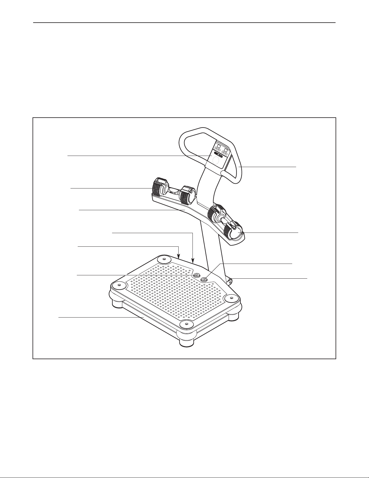
Before reading further, please familiarize yourself with
the parts that are labeled in the drawing below.
Handlebar
Dumbbell
Start Button
Stop Button
Base
Wheel
5
Page 6
PART IDENTIFICATION CHART
M10 Split
Washer (38)
M4 x 19mm
Screw (45)
M10 x 35mm Screw (34)
M10 x 20mm
Patch Screw (28)
M10 x 62mm Patch Screw (37)
M10 x 114mm Bolt (33)
M5 x 38mm Screw (40)
M10 x 55mm Patch Screw (20)
M10 x 50mm Patch Screw (51)
M4 x 16mm
Patch Screw (26)
M10 x 68mm Bolt (55)
M10 Locknut (32)
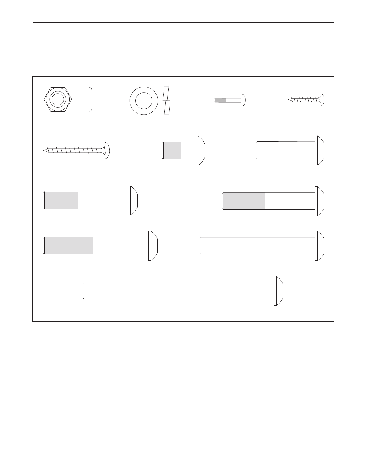
See the drawings below to identify small parts used in assembly. The number in parentheses by each drawing is
the key number of the part, from the PART LIST near the end of this manual. Note: If a part is not in the hard-
ware kit, check to see if it has been preattached.
6
Page 7
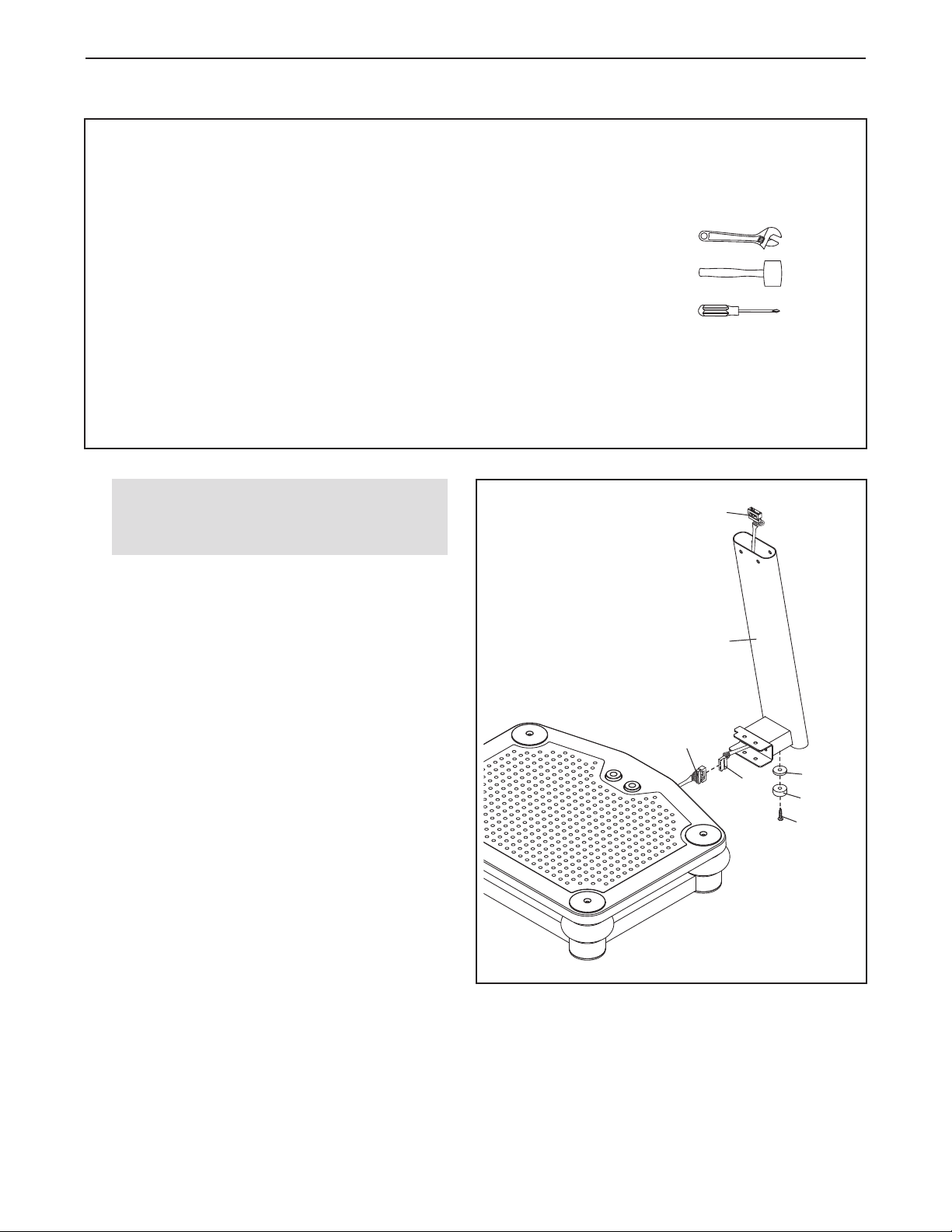
ASSEMBLY
• To hire an authorized service technician to
assemble the vibration platform in your home,
call 1-800-445-2480.
• Assembly requires two persons.
• Because of its size and weight, assemble the
vibration platform in the location where it will
be used. Make sure that there is enough clearance to walk around the vibration platform as
you assemble it.
• Place all parts in a cleared area and remove
the packing materials. Do not dispose of the
packing materials until you complete all
assembly steps.
1.
Before beginning assembly, make sure
that you have read and understand the
information in the box above.
Attach a Rubber Spacer (29) and a Foot (13) to
the Lower Upright (1) with an M10 x 35mm
Screw (34).
Next, locate the Wire Harness (43) inside the
Lower Upright (1). Connect the Wire Harness to
the base wire as shown. Then, pull the Wire
Harness out of the top of the Lower Upright.
• To identify small parts, see page 6.
• The following tools (not included) may be
equired for assembly:
r
one adjustable wrench
one rubber mallet
one Phillips screwdriver
Assembly will be more convenient if you have a
socket set, a set of open-end or closed-end
wrenches, or a set of ratchet wrenches.
1
43
1
Base
Wire
43
29
13
34
7
Page 8
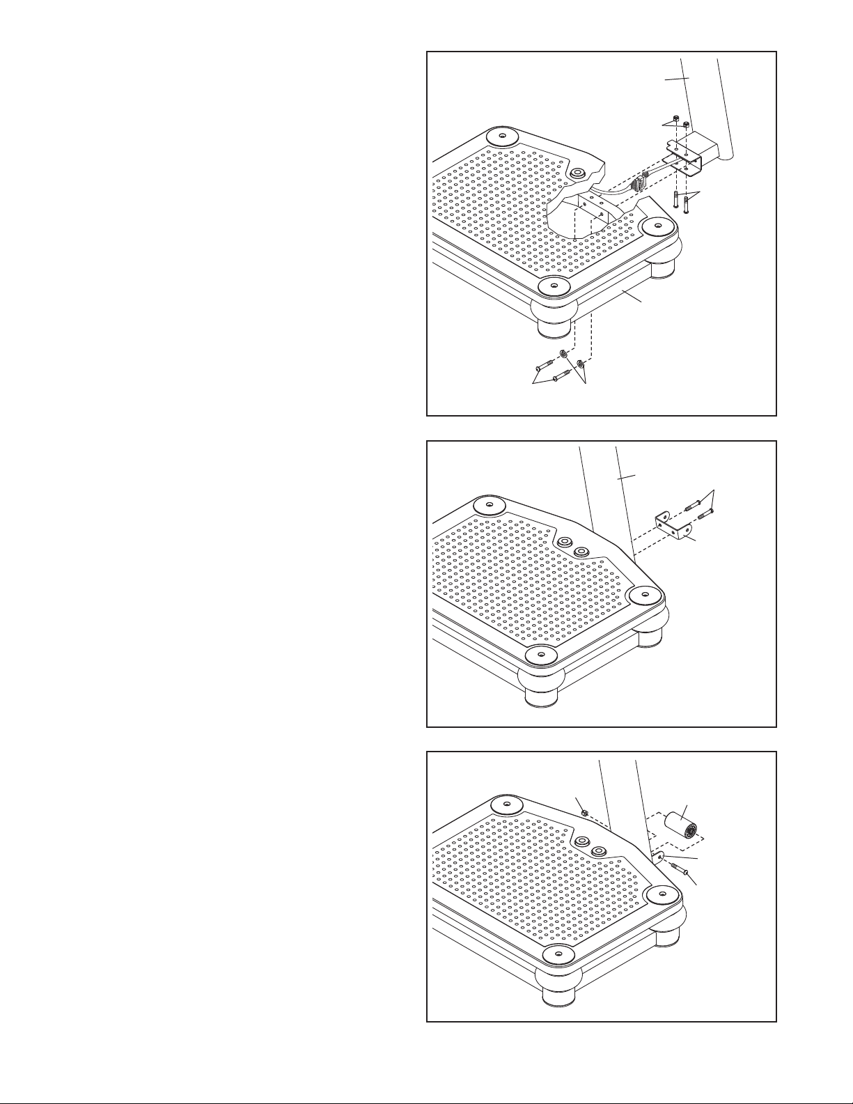
2. Tip: Be careful not to pinch the wires during
this step.
ith the help of a second person, carefully tip
W
the Base (5) onto its side.
Attach the Lower Upright (1) to the Base (5)
with two M10 x 55mm Patch Screws (20), two
M10 Split Washers (38), two M10 x 68mm Bolts
(55), and two M10 Locknuts (32).
2
1
32
5
5
5
3. Tip: Orient the Wheel Bracket (35) so that
the arrow sticker is pointing upward.
Attach the Wheel Bracket (35) to the Lower
Upright (1) with two M10 x 20mm Patch Screws
(28).
4. Attach the Wheel (30) to the Wheel Bracket (35)
with an M10 x 114mm Bolt (33) and an M10
Locknut (32). Do not overtighten the Locknut;
the Wheel must rotate freely.
20
3
4
32
38
1
28
35
30
Note: If the Wheel (30) rattles when the
vibration platform is in use, tighten the M10
Locknut (32) until the rattling stops.
35
33
8
Page 9
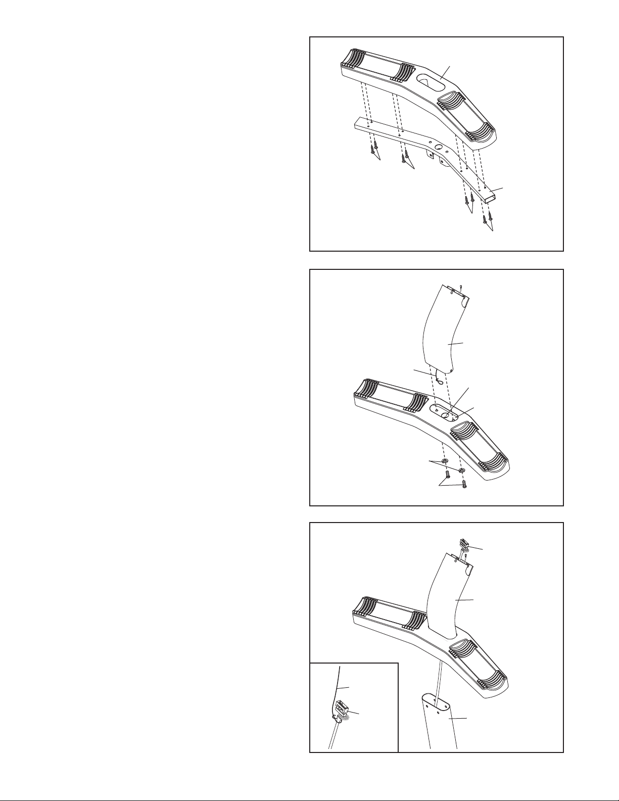
5. Attach the Weight Rest (42) to the Weight Rest
Frame (41) with eight M5 x 38mm Screws (40).
Do not tighten the Screws yet.
5
42
6. Locate the wire tie inside the Upper Upright (36).
Insert the wire tie through the hole in the Weight
Rest Frame (41).
Next, attach the Upper Upright (36) to the
Weight Rest Frame (41) with two M10 x 50mm
Patch Screws (51) and two M10 Split Washers
(38).
40
40
41
40
40
6
36
Wire Tie
Hole
41
7. Have a second person hold the Upper Upright
(36) near the Lower Upright (1).
See the inset drawing. Tie the lower end of the
wire tie to the Wire Harness (43) as shown.
Then, pull the upper end of the wire tie until the
Wire Harness is routed through the Upper
Upright (36).
38
51
7
43
36
Wire Tie
43
1
9
Page 10
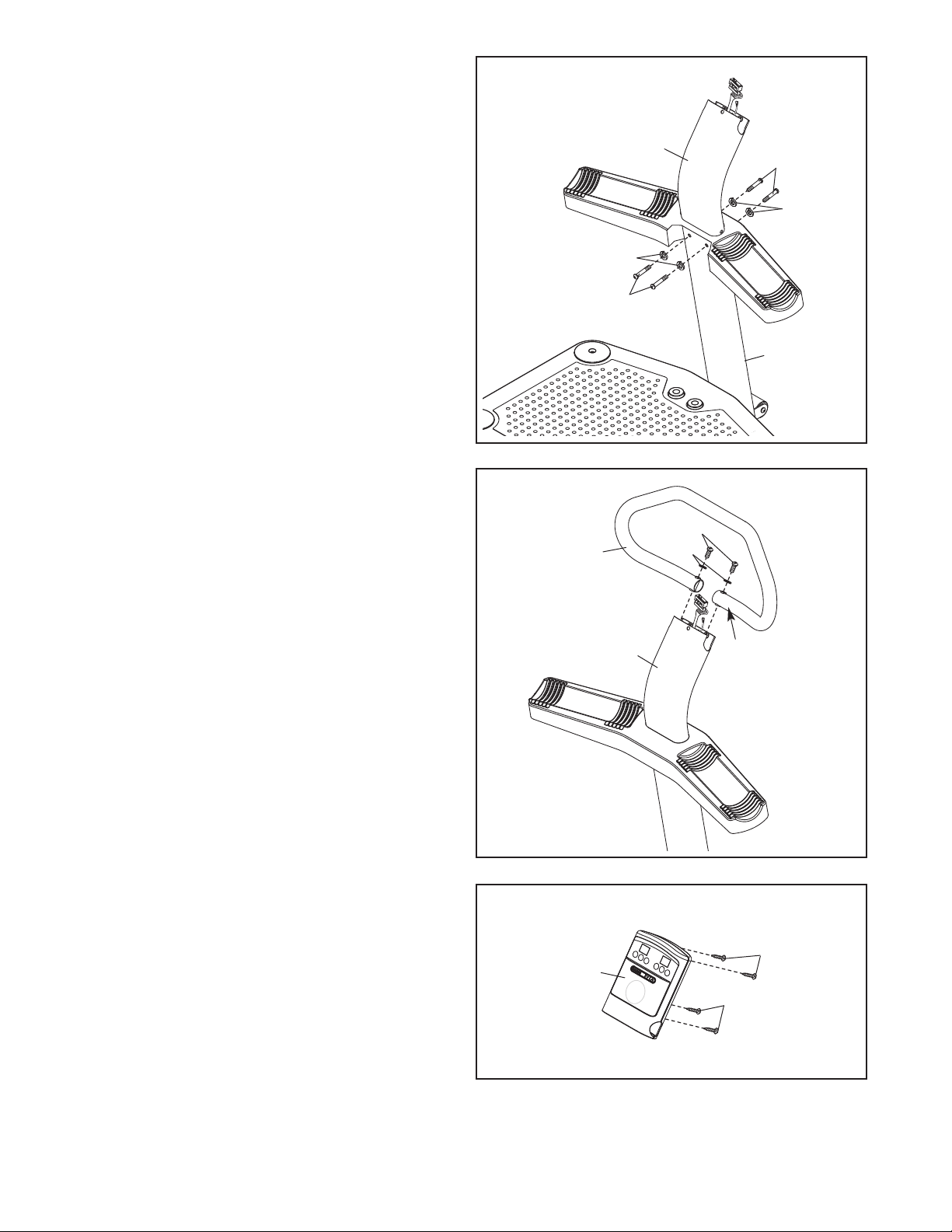
8. Tip: Be careful not to pinch the wires during
his step.
t
ttach the Upper Upright (36) to the Lower
A
Upright (1) with four M10 x 20mm Patch Screws
(28) and four M10 Split Washers (38).
ee step 5. Tighten the eight M5 x 38mm
S
Screws (40).
8
6
3
38
28
8
2
38
1
9. Tip: Orient the Handlebar (39) so that the
sticker marked with an “R” is in the location
shown.
Attach the Handlebar (39) to the Upper Upright
(36) with two M10 x 62mm Patch Screws (37)
and two M10 Split Washers (38).
10. Remove the four M4 x 12mm Self-tapping
Screws (27) from the back of the Console (3).
Set the Self-tapping Screws aside until step
13.
9
10
39
37
38
36
3
“R”
27
27
10
Page 11
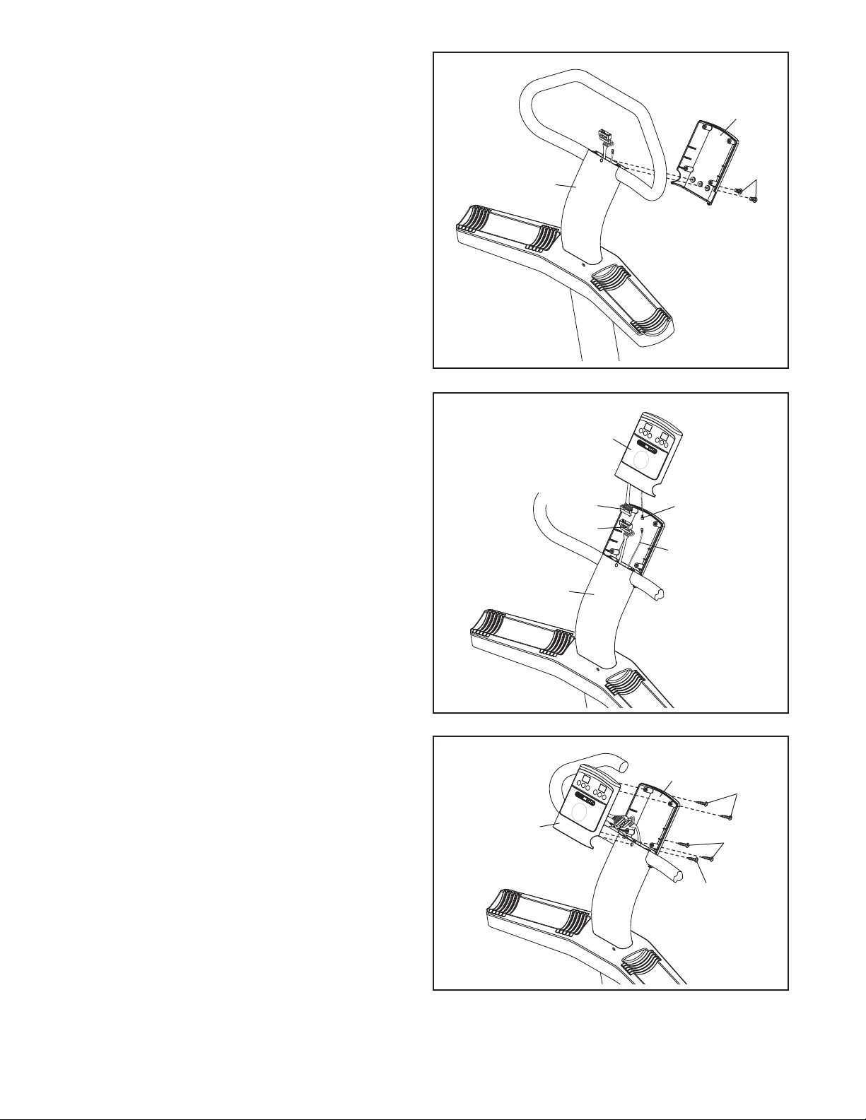
11. Attach the back of the Console (3) to the Upper
Upright (36) with two M4 x 16mm Patch Screws
(26). Do not tighten the Patch Screws yet.
1
1
3
12. While a second person holds the front of the
Console (3) near the Upper Upright (36), connect the console ground wire to the Ground
Wire (52).
Next, connect the console wire to the Wire
Harness (43).
Then, insert the wires into the Upper Upright
(36).
12
36
Console
Wire
43
26
3
Console
Ground Wire
52
13. Tip: Be careful not to pinch the wires during
this step.
Attach the front of the Console (3) to the back
of the Console with the four M4 x 12mm Selftapping Screws (27) you removed in step 10
and an M4 x 19mm Screw (45).
See step 11. Tighten the two M4 x 16mm
Patch Screws (26).
36
13
3
27
3
27
45
11
Page 12
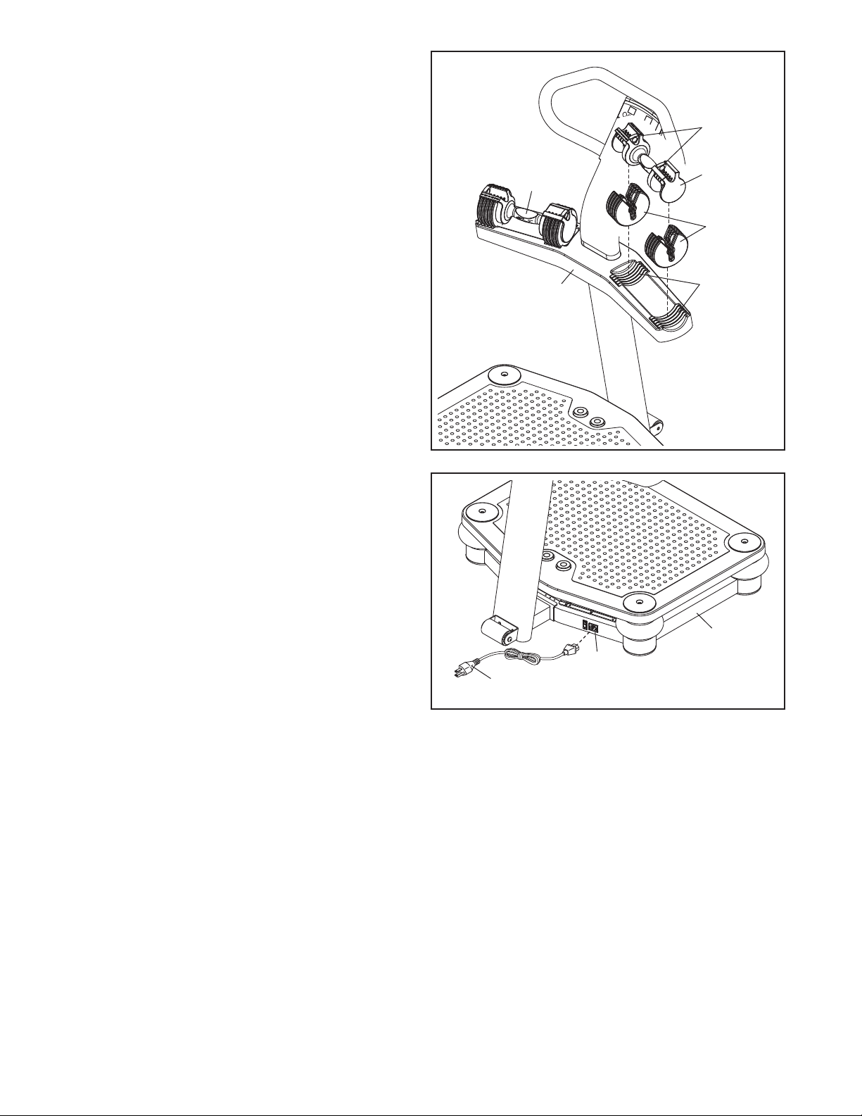
14. Set ten weight plates into the indicated slots in
the right side of the Weight Rest (42).
ext, lift the two selector pins on a Dumbbell
N
(44), and slide the selector pins to the adjust-
ent holes marked “2.5.” Place the Dumbbell
m
on the weight plates.
Then, lift the two selector pins and slide them to
the adjustment holes marked “15.”
Repeat this step with the other Dumbbell (44).
14
Selector
Pins
44
44
Weight
Plates
15. Plug the Power Cord (17) into the Receptacle
(18) located on the Base (5).
15
17
42
Slots
5
18
16. Make sure that all parts are properly tightened before you use the vibration platform.
12
Page 13
HOW TO USE THE VIBRATION PLATFORM
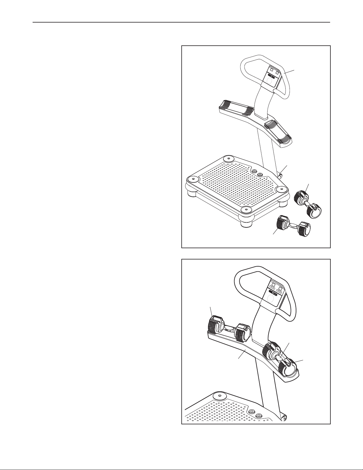
OW TO MOVE THE VIBRATION PLATFORM
H
Before moving the vibration platform, unplug
the power cord and remove the dumbbells from
he weight rest.
t
Hold the handlebar and place one foot against the
wheel. Tilt the vibration platform until it rolls freely
on the wheel. Carefully move the vibration platform
to the desired location. To reduce the risk of
injury, use extreme caution while moving the
vibration platform. Do not move the vibration
platform over an uneven surface.
Handlebar
Wheel
Dumbbell
HOW TO USE THE ADJUSTABLE-WEIGHT
DUMBBELLS
Each dumbbell handle can be used with two, four,
six, eight, or ten weight plates; each dumbbell handle can also be used without weight plates.
To select the desired number of weight plates, first
set a dumbbell on the weight rest as shown. Next,
lift one of the selector pins, slide the selector pin to
one of the adjustment holes, and then release the
selector pin. Rock the selector pin from side to side
to make sure that it is fully inserted into one of the
adjustment holes. Adjust the other selector pin on
the dumbbell in the same way. Always attach the
same number of weight plates to both sides of
each dumbbell handle.
To use the dumbbell, lift it straight upward off the
weight rest, making sure that the unattached weight
plates remain on the weight rest.
Selector
Pin
Weight
Rest
Dumbbell
Handle
Weight
Plates
13
Page 14
HOW TO PLUG IN THE POWER CORD
DANGER: Improper connection of
the equipment-grounding conductor can
esult in an increased risk of electric shock.
r
Check with a qualified electrician or serviceman if you are in doubt as to whether the
product is properly grounded. Do not modify
the plug provided with the product—if it will
not fit the outlet, have a proper outlet installed
by a qualified electrician.
Your vibration platform, like any other type of sophisticated electronic equipment, can be seriously damaged
by sudden voltage changes in your homeʼs power.
Voltage surges, spikes, and noise interference can
result from weather conditions or from other appliances being turned on or off. To decrease the
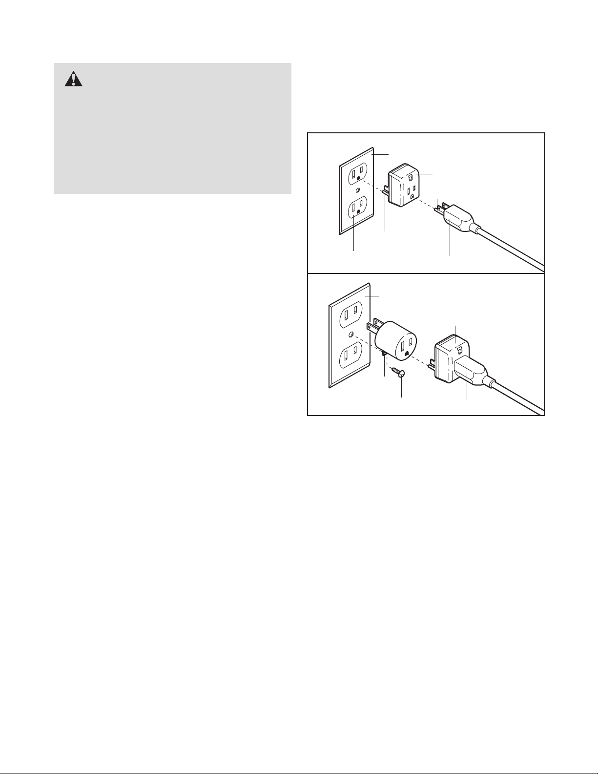
possibility of your vibration platform being damaged, always use a surge suppressor with your
vibration platform (see drawing 1 at the right). To
purchase a surge suppressor, see your local PROFORM store or call the telephone number on the
front cover of this manual and order part number
146148, or see your local electronics store.
This product is for use on a nominal 120-volt circuit,
and has a grounding plug that looks like the plug illustrated in drawing 1 below. A temporary adapter that
ooks like the adapter illustrated in drawing 2 may be
l
used to connect the surge suppressor to a 2-pole
eceptacle as shown in drawing 2 if a properly
r
grounded outlet is not available.
1
Grounded Outlet Box
Surge Suppressor
Grounding Pin
Grounding Pin
Grounded Outlet
2
Grounded Outlet Box
Adapter
Grounding Plug
Surge Suppressor
Use only a single-outlet surge suppressor that is
UL 1449 listed as a transient voltage surge suppressor (TVSS). The surge suppressor must have
a UL suppressed voltage rating of 400 volts or
less and a minimum surge dissipation of 450
joules. The surge suppressor must be electrically
rated for 120 volts AC and 15 amps. There must be
a monitoring light on the surge suppressor to indicate whether it is functioning properly.
This product must be grounded. If it should mal-
function or break down, grounding provides a path of
least resistance for electric current to reduce the risk
of electric shock. This product is equipped with a cord
having an equipment-grounding conductor and a
grounding plug. Plug the power cord into a surge
suppressor, and plug the surge suppressor into an
appropriate outlet that is properly installed and
grounded in accordance with all local codes and
ordinances. IMPORTANT: The vibration platform is
not compatible with GFCI-equipped outlets.
Lug
Metal Screw
The temporary adapter should be used only until a
properly grounded outlet (drawing 1) can be installed
by a qualified electrician.
The green-colored rigid ear, lug, or the like extending
from the adapter must be connected to a permanent
ground such as a properly grounded outlet box cover.
Whenever the adapter is used it must be held in place
by a metal screw. Some 2-pole receptacle outlet
box covers are not grounded. Contact a qualified
electrician to determine if the outlet box cover is
grounded before using an adapter.
Grounding Plug
14
Page 15
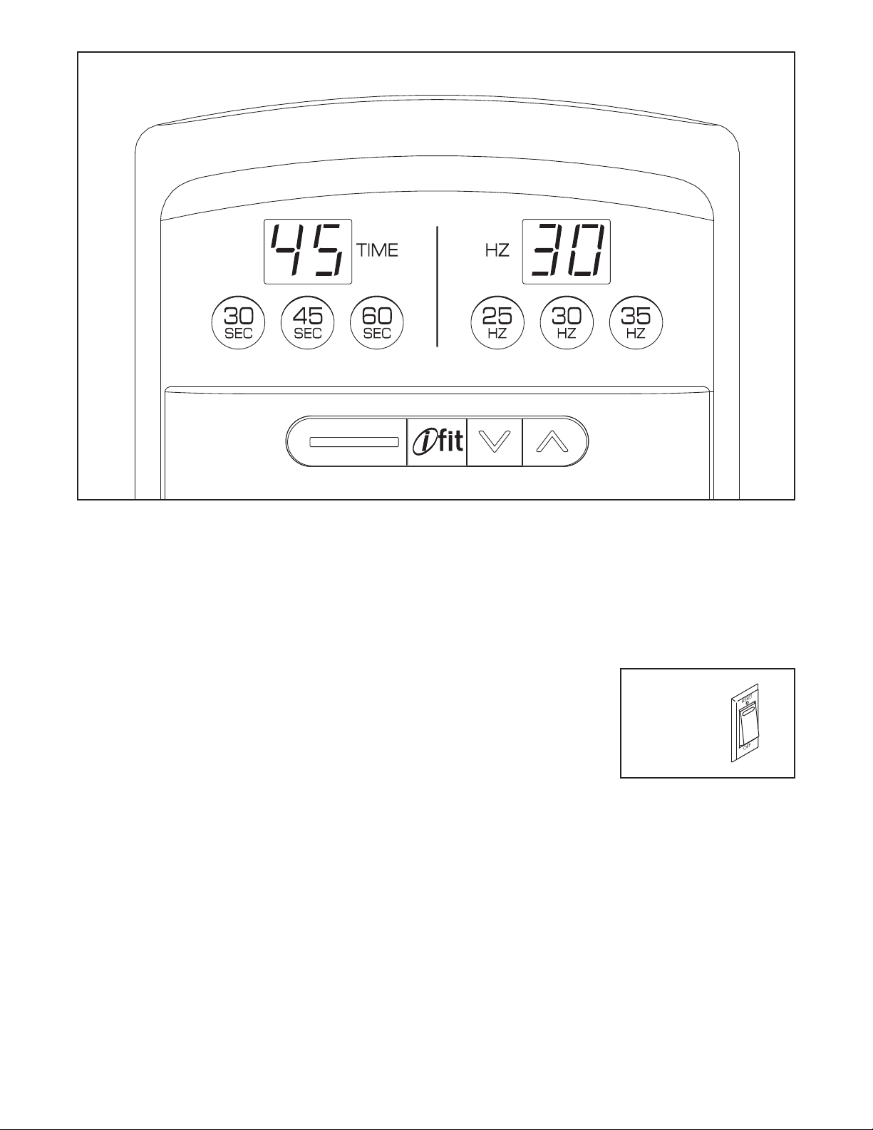
ONSOLE DIAGRAM
C
CONSOLE FEATURES
The console offers a selection of features designed to
make your workouts more effective and enjoyable.
You can change the time and frequency of your vibration sessions with the touch of a button.
The console also features the new iFit interactive
workout system. The iFit interactive workout system is
compatible with iFit cards containing workout programs designed to help you achieve specific fitness
goals. IFIT programs control the time and frequency of
the vibration platform while the voice of a personal
trainer coaches you and motivates you through your
workouts. IFIT cards are available separately. To pur-
chase iFit cards, go to www.iFit.com or call the
telephone number on the front cover of this manual. iFit cards are also available at select stores.
HOW TO TURN ON THE POWER
IMPORTANT: If the vibration platform has been
exposed to cold temperatures, allow it to warm to
room temperature before turning on the power. If
you do not do this, the console or other electronic
components may become damaged.
Plug the power cord
into the receptacle on
the base of the vibration platform (see
assembly step 15 on
page 12). Then, plug
the power cord into a
120-volt outlet. Next,
locate the reset/off circuit breaker on the vibration platform near the power cord. Make sure that the circuit
breaker is in the reset position.
EXERCISE FORM
See the accompanying exercise DVD to learn the correct form for several exercises that can be performed
on the vibration platform. When standing on the vibration platform, bend your knees slightly and balance
your weight on the balls of your feet.
Reset
Position
15
Page 16
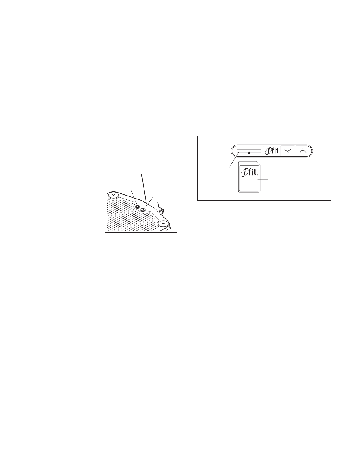
HOW TO USE THE MANUAL MODE
HOW TO USE AN IFIT PROGRAM
1. Turn on the power.
See HOW TO TURN ON THE POWER on page
5.
1
2. Select the desired vibration time.
Press the desired time button to select a vibration
time of 30, 45, or 60 seconds. The display will
show which length of time you have selected.
3. Select the desired vibration frequency.
Press the desired frequency button to select a
vibration frequency of 25, 30, or 35 hertz. The display will show which frequency you have selected.
4. Start a vibration session.
Press the start button on the platform
to start a vibration
session.
Stop
Button
Start
Button
1. Turn on the power.
See HOW TO TURN ON THE POWER on page
5.
1
2.
Insert an iFit card and select a program.
To use an iFit program, insert an iFit card into the
iFit slot; make sure that the iFit card is oriented so
the metal contacts are face down and are facing
the slot. When the iFit card is properly inserted,
the indicator next to the slot will light and the number of the iFit program will appear in the display.
iFit Slot
iFit Card
5. Stop or pause a vibration session.
Press the stop button (see the drawing above) on
the platform to stop or pause a vibration session.
Press the start button to continue the vibration
session.
Note: When the session ends, a tone will sound to
alert you, and the vibration platform will automatically stop.
6. Start additional vibration sessions as desired.
Repeat steps 2–5 for as many additional vibration
sessions as desired. IMPORTANT: It is recom-
mended that you use the vibration platform for
no more than 15 minutes per day and no more
than 3 times per week.
7. When you are finished, switch the reset/off
switch to the off position and unplug the
power cord.
Next, select the desired program on the iFit card
by pressing the increase and decrease buttons
next to the iFit slot.
A moment after you select a program, the voice of
a personal trainer will begin guiding you through
your workout.
3.
When you are finished exercising, remove the
iFit card.
Remove the iFit card when you are finished exercising. Store the iFit card in a secure place.
16
Page 17
TROUBLESHOOTING
Inspect all parts of the vibration platform regularly. Replace any worn parts immediately. Outer surfaces of the
vibration platform can be cleaned with a damp cloth and a mild, non-abrasive detergent; do not use solvents
o clean the vibration platform.
t
Most vibration platform problems can be solved by following the simple steps below. Find the symptom
that applies, and follow the steps listed. If further assistance is needed, call the telephone number on
the front cover of this manual.
PROBLEM: The power does not turn on
SOLUTION: a. Make sure that the power cord is plugged into a surge suppressor, and that the surge suppres-
sor is plugged into a properly grounded outlet (see page 14). Use only a single-outlet surge
suppressor that meets all of the specifications described on page 14. IMPORTANT: The vibra-
tion platform is not compatible with GFCI-equipped outlets.
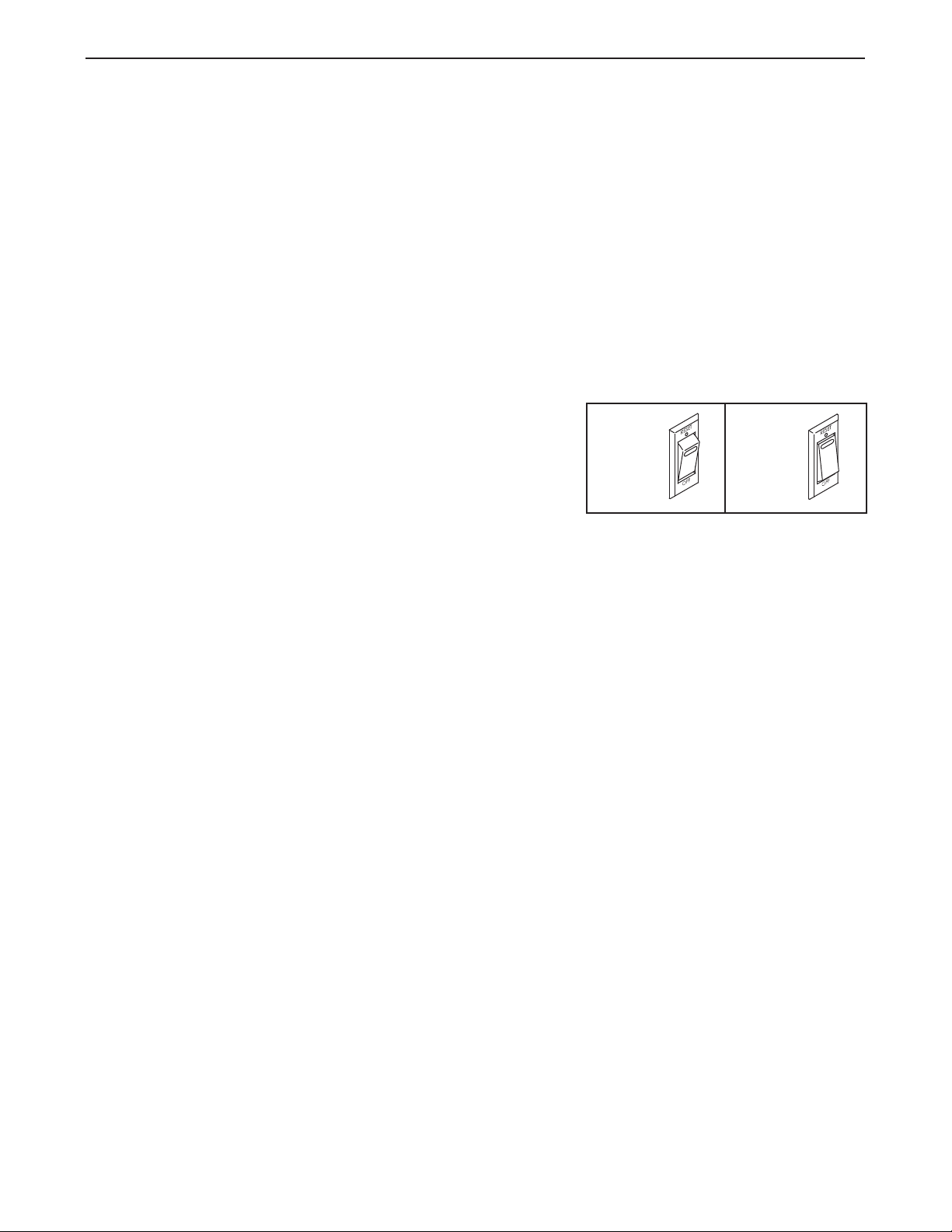
b. Check the reset/off circuit breaker located on the
vibration platform base near the power cord. If the
switch protrudes as shown, the circuit breaker has
tripped. To reset the circuit breaker, wait for five
minutes and then press the switch back in.
PROBLEM:The power turns off during use
SOLUTION: a. Check the reset/off circuit breaker (see the drawing above). If the circuit breaker has tripped,
wait for five minutes and then press the switch back in.
b. Make sure that the power cord is plugged in. If the power cord is plugged in, unplug it, wait for
five minutes, and then plug it back in.
c. If the vibration platform still will not run, please see the front cover of this manual.
c
Tripped
Reset
17
Page 18

PART LIST—Model No. PFVB14988.0 R1209A
Key No. Qty. Description Key No. Qty. Description
11Lower Upright
21Platform Cover
3
41Platform Plate
51Base
61Vibration Platform
71Stop Button
81Start Button
91Controller Box
10 1 Controller
11 1 Controller Cover
12 1 Motor
13 5 Foot
14 4 Shock Absorber Cover
15 4 Shock Absorber
16 4 Platform Cap
17 1 Power Cord
18 1 Receptacle
19 1 Reset/Off Circuit Breaker
20 2 M10 x 55mm Patch Screw
21 2 Copper Plate
22 2 Spring
23 2 M8 x 16mm Screw
24 4 M10 x 46mm Flat Head Screw
25 4 M8 x 30mm Screw
26 2 M4 x 16mm Patch Screw
27 4 M4 x 12mm Self-tapping Screw
28 6 M10 x 20mm Patch Screw
29 1 Rubber Spacer
30 1 Wheel
1 Console
31 4 M4 x 8mm Screw
32 3 M10 Locknut
3 1 M10 x 114mm Bolt
3
34 5 M10 x 35mm Screw
35 1 Wheel Bracket
36 1 Upper Upright
37 2 M10 x 62mm Patch Screw
38 10 M10 Split Washer
39 1 Handlebar
40 8 M5 x 38mm Screw
41 1 Weight Rest Frame
42 1 Weight Rest
43 1 Wire Harness
44 1 Dumbbell (Pair)
45 1 M4 x 19mm Screw
46 4 M8 Washer
47 4 M8 Split Washer
48 4 Frame Cover
49 1 Motor Mounting Bracket
50 1 Motor Cover
51 2 M10 x 50mm Patch Screw
52 1 Ground Wire
53 3 M4 x 12mm Screw
54 1 Grommet
55 2 M10 x 68mm Bolt
56 1 Switch Wire Harness
*–Wiring Tie
*–Assembly Tool
*–Userʼs Manual
*–DVD
Note: Specifications are subject to change without notice. For information about ordering replacement parts, see
the back cover of this manual. *These parts are not illustrated.
18
Page 19
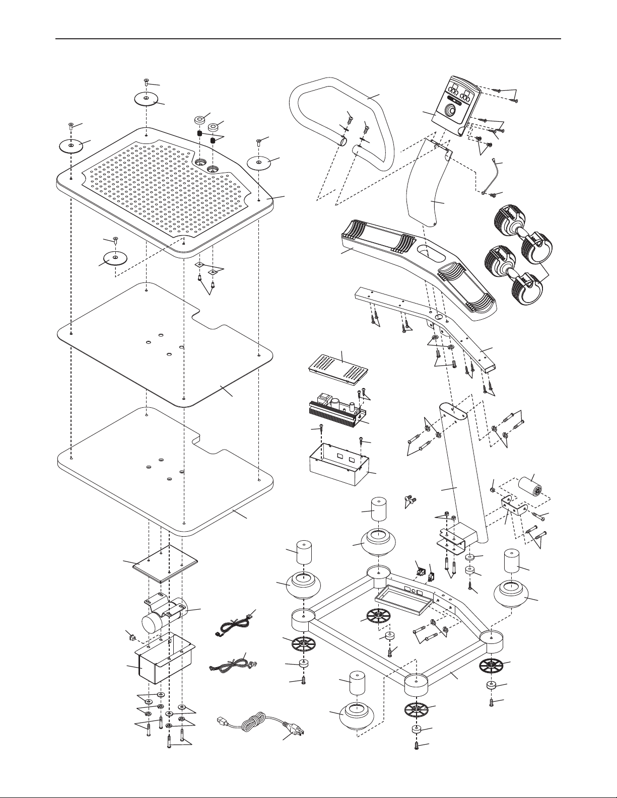
EXPLODED DRAWING—Model No. PFVB14988.0 R1209A
1
30
2
4
6
12
15
14
16
13
9
10
11
41
42
36
3
39
48
48
48
34
15
14
16
13
34
20
15
14
16
13
34
16
13
34
5
15
14
48
7
8
2
2
23
21
25
25
17
43
24
24
24
24
37
27
26
45
2
7
40
51
28
40
40
40
32
35
33
28
29
13
34
18
19
31
47
46
47
46
38
28
38
38
38
37
38
38
49
50
52
53
54
44
53
55
32
31
31
56
19
Page 20

ORDERING REPLACEMENT PARTS
To order replacement parts, please see the front cover of this manual. To help us assist you, be prepared to
rovide the following information when contacting us:
p
• the model number and serial number of the product (see the front cover of this manual)
the name of the product (see the front cover of this manual)
•
• the key number and description of the replacement part(s) (see the PART LIST and the EXPLODED
DRAWING near the end of this manual)
LIMITED WARRANTY
IMPORTANT: You must register this product within 30 days of the purchase date to avoid added
fees for service needed under warranty. Go to www.proformservice.com/registration.
ICON Health & Fitness, Inc. (ICON) warrants this product to be free from defects in workmanship and
material, under normal use and service conditions. Parts and labor are warranted for one (1) year from
the date of purchase.
This warranty extends only to the original purchaser. ICONʼs obligation under this warranty is limited to
repairing or replacing, at ICONʼs option, the product through one of its authorized service centers. All
repairs for which warranty claims are made must be preauthorized by ICON. If the product is shipped to
a service center, freight charges to and from the service center will be the customerʼs responsibility. For
replacement parts shipped while the product is under warranty, the customer will be responsible for a minimal handling charge. For in-home service, the customer will be responsible for a minimal trip charge. This
warranty does not extend to any damage to a product caused by or attributable to freight damage, abuse,
misuse, improper or abnormal usage, or repairs not provided by an ICON authorized service center; to
products used for commercial or rental purposes or as store display models; or to products transported
or purchased outside the US. No other warranty beyond that specifically set forth above is authorized by
ICON.
ICON is not responsible or liable for indirect, special, or consequential damages arising out of or in connection with the use or performance of the product; damages with respect to any economic loss, loss of
property, loss of revenues or profits, loss of enjoyment or use, or costs of removal or installation; or other
consequential damages of whatsoever nature. Some states do not allow the exclusion or limitation of incidental or consequential damages. Accordingly, the above limitation may not apply to you.
The warranty extended hereunder is in lieu of any and all other warranties, and any implied warranties of
merchantability or fitness for a particular purpose are limited in their scope and duration to the terms set
forth herein. Some states do not allow limitations on how long an implied warranty lasts. Accordingly, the
above limitation may not apply to you.
This warranty gives you specific legal rights. You may also have other rights that vary from state to state.
ICON Health & Fitness, Inc., 1500 S. 1000 W., Logan, UT 84321-9813
Part No. 264004 R1209A Printed in China © 2009 ICON IP, Inc.
 Loading...