

Page 1
www.proform.com
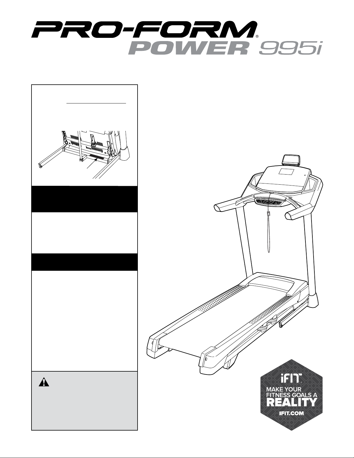
Model No. PFTL99513.3
Serial No.
Write the serial number in the space
above for reference.
Serial Number
Decal
ACTIVATE YOUR
WARRANTY
To register your product and
activate your warranty today,
go to www.proformservice.com/
registration.
USER’S MANUAL
CUSTOMER CARE
For service at any time, go to
www.proformservice.com.
Or call 1-888-533-1333
Mon.–Fri. 6 a.m.–6 p.m. MT
Sat. 8 a.m.–12 p.m. MT
Please do not contact the store.
CAUTION
Read all precautions and instructions in this manual before using
this equipment. Save this manual
for future reference.
Page 2
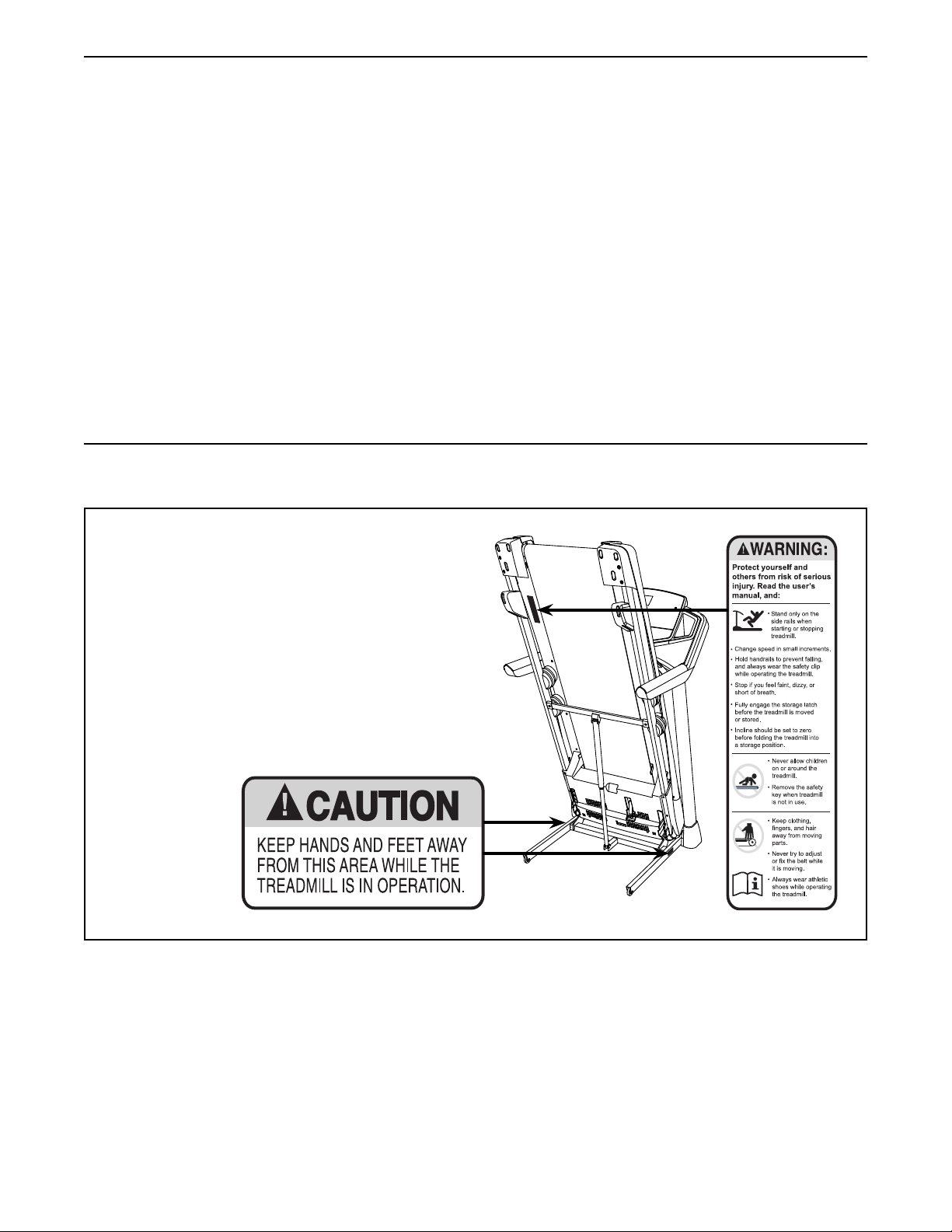
TABLE OF CONTENTS
WARNING DECAL PLACEMENT . . . . . . . . . . . . . . . . . . . . . . . . . . . . . . . . . . . . . . . . . . . . . . . . . . . . . . . . . . . . . . .2
IMPORTANT PRECAUTIONS ..................................................................3
BEFORE YOU BEGIN. . . . . . . . . . . . . . . . . . . . . . . . . . . . . . . . . . . . . . . . . . . . . . . . . . . . . . . . . . . . . . . . . . . . . . . .7
PART IDENTIFICATION CHART. . . . . . . . . . . . . . . . . . . . . . . . . . . . . . . . . . . . . . . . . . . . . . . . . . . . . . . . . . . . . . . . 8
ASSEMBLY . . . . . . . . . . . . . . . . . . . . . . . . . . . . . . . . . . . . . . . . . . . . . . . . . . . . . . . . . . . . . . . . . . . . . . . . . . . . . . . .9
HOW TO USE THE TREADMILL ..............................................................19
HOW TO FOLD AND MOVE THE TREADMILL . . . . . . . . . . . . . . . . . . . . . . . . . . . . . . . . . . . . . . . . . . . . . . . . . . .29
MAINTENANCE AND TROUBLESHOOTING .....................................................30
EXERCISE GUIDELINES ....................................................................33
PART LIST. . . . . . . . . . . . . . . . . . . . . . . . . . . . . . . . . . . . . . . . . . . . . . . . . . . . . . . . . . . . . . . . . . . . . . . . . . . . . . . . 34
EXPLODED DRAWING A ....................................................................36
ORDERING REPLACEMENT PARTS. . . . . . . . . . . . . . . . . . . . . . . . . . . . . . . . . . . . . . . . . . . . . . . . . . . Back Cover
LIMITED WARRANTY. . . . . . . . . . . . . . . . . . . . . . . . . . . . . . . . . . . . . . . . . . . . . . . . . . . . . . . . . . . . . . . Back Cover
WARNING DECAL PLACEMENT
This drawing shows the locations of the warning
decals. If a decal is missing or illegible, call
the telephone number on the front cover of
this manual and request a free replacement
decal. Apply the decal in the location shown.
Note: The decals may not be shown at actual size.
PROFORM is a registered trademark of ICON Health & Fitness, Inc.
2
Page 3

IMPORTANT PRECAUTIONS
WARNING: To reduce the risk of burns, fire, electric shock, or injury to persons, read
all important precautions and instructions in this manual and all warnings on your treadmill before
using your treadmill. ICON assumes no responsibility for personal injury or property damage sustained by or through the use of this product.
1. It is the responsibility of the owner to ensure
that all users of this treadmill are adequately
informed of all warnings and precautions.
2. Before beginning any exercise program,
consult your physician. This is especially
important for persons over age 35 or persons
with pre-existing health problems.
3. Use the treadmill only as described in this
manual.
4. The treadmill is intended for home use only.
Do not use the treadmill in any commercial,
rental, or institutional setting.
5. Keep the treadmill indoors, away from moisture and dust. Do not put the treadmill in a
garage or covered patio, or near water.
6. Place the treadmill on a level surface, with
at least 8 ft. (2.4 m) of clearance behind it
and 2 ft. (0.6 m) on each side. Do not place
the treadmill on any surface that blocks air
openings. To protect the floor or carpet from
damage, place a mat under the treadmill.
7. Do not operate the treadmill where aerosol
products are used or where oxygen is being
administered.
8. Keep children under age 12 and pets away
from the treadmill at all times.
12. Plug the power cord into a surge suppressor
(not included), and plug the surge suppressor into an appropriate outlet (see page 19).
To avoid overloading the circuit, do not plug
other electrical devices, except for low-power
devices such as cell phone chargers, into
the surge suppressor or into an outlet on the
same circuit.
13. Use only a surge suppressor that meets all of
the specifications described on page 19. To
purchase a surge suppressor, see your local
PROFORM dealer, call the telephone number
on the front cover of this manual, or see your
local electronics store.
14. Failure to use a properly functioning surge
suppressor could result in damage to the
control system of the treadmill. If the control
system is damaged, the walking belt may
slow, accelerate, or stop unexpectedly, which
may result in a fall and serious injury.
15. Keep the power cord and the surge suppressor away from heated surfaces.
16. Never move the walking belt while the power
is turned off. Do not operate the treadmill
if the power cord or plug is damaged, or if
the treadmill is not working properly. (See
MAINTENANCE AND TROUBLESHOOTING
on page 30 if the treadmill is not working
properly.)
9. The treadmill should be used only by persons weighing 350 lbs. (159 kg) or less.
10. Never allow more than one person on the
treadmill at a time.
11. Wear appropriate exercise clothes while
using the treadmill. Do not wear loose
clothes that could become caught in the
treadmill. Athletic support clothes are recommended for both men and women. Always
wear athletic shoes. Never use the treadmill
with bare feet, wearing only stockings, or in
sandals.
17. Read, understand, and test the emergency
stop procedure before using the treadmill
(see HOW TO TURN ON THE POWER on
page 21). Always wear the clip while using the
treadmill.
18. Always stand on the foot rails when starting
or stopping the walking belt. Always hold the
handrails while using the treadmill.
19. When a person is walking on the treadmill,
the noise level of the treadmill will increase.
3
Page 4

20. Keep fingers, hair, and clothing away from
the moving walking belt.
21. The treadmill is capable of high speeds.
Adjust the speed in small increments to
avoid sudden jumps in speed.
25. When folding or moving the treadmill, make
sure that the storage latch is holding the
frame securely in the storage position.
26. Never insert any object into any opening on
the treadmill.
22. The heart rate monitor is not a medical
device. Various factors, including the user’s
movement, may affect the accuracy of heart
rate readings. The heart rate monitor is
intended only as an exercise aid in determining heart rate trends in general.
23. Never leave the treadmill unattended while
it is running. Always remove the key, press
the power switch into the off position (see
the drawing on page 7 for the location of the
power switch), and unplug the power cord
when the treadmill is not in use.
24. Do not attempt to move the treadmill until it
is properly assembled. (See ASSEMBLY on
page 9, and HOW TO FOLD AND MOVE THE
TREADMILL on page 29.) You must be able
to safely lift 45 lbs. (20 kg) to raise, lower, or
move the treadmill.
SAVE THESE INSTRUCTIONS
27. Inspect and properly tighten all parts of the
treadmill regularly.
28. DANGER: Always unplug the power
cord immediately after use, before cleaning the treadmill, and before performing the
maintenance and adjustment procedures
described in this manual. Never remove the
motor hood unless instructed to do so by an
authorized service representative. Servicing
other than the procedures in this manual
should be performed by an authorized service representative only.
29. Over exercising may result in serious injury
or death. If you feel faint, if you become short
of breath, or if you experience pain while
exercising, stop immediately and cool down.
4
Page 5

5
Page 6
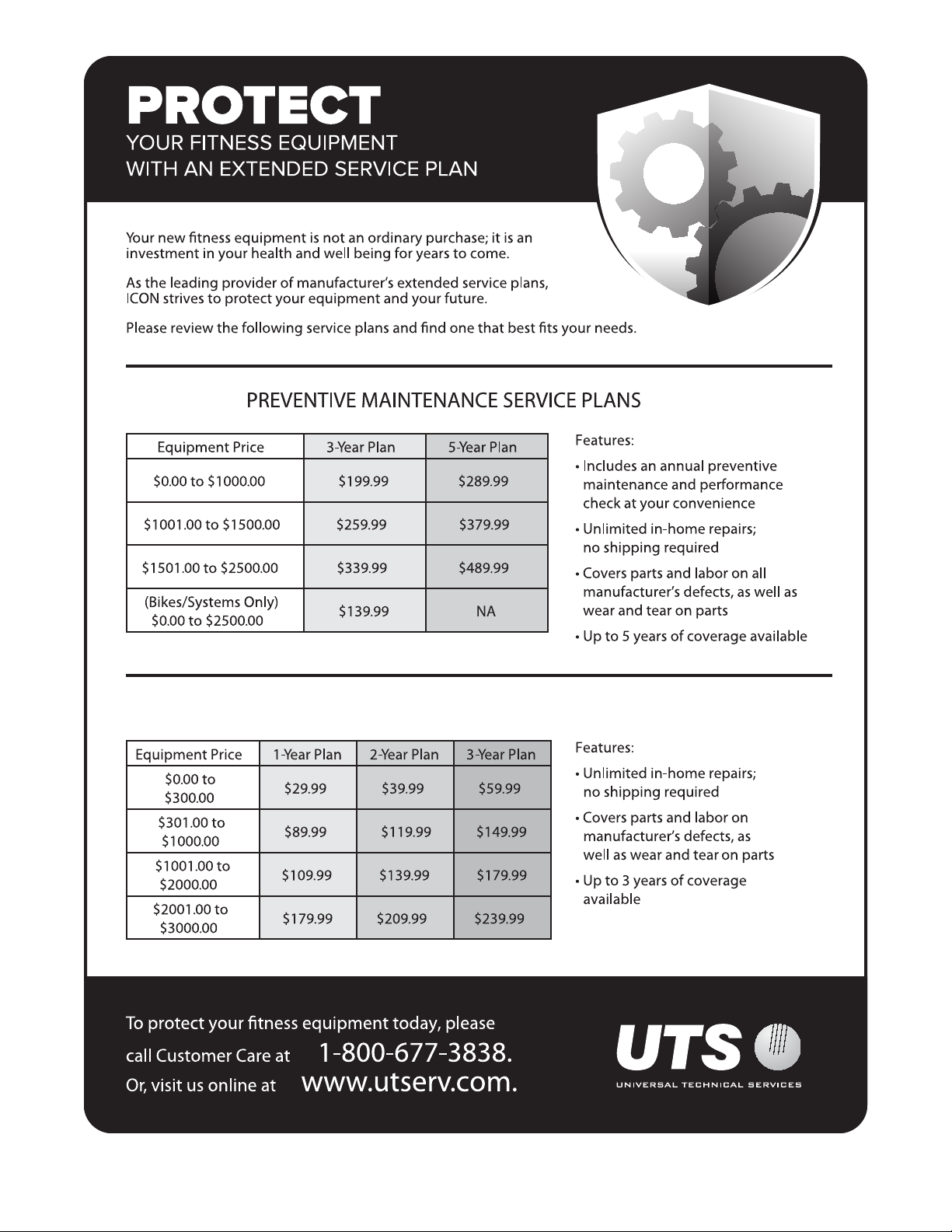
STANDARD SERVICE PLANS
all
6
Page 7
BEFORE YOU BEGIN
Thank you for selecting the revolutionary
PROFORM® Power 995i treadmill. The Power 995i
treadmill offers an impressive selection of features
designed to make your workouts at home more effective and enjoyable. And when you’re not exercising, the
unique treadmill can be folded up, requiring less than
half the oor space of other treadmills.
For your benet, read this manual carefully before
using the treadmill. If you have questions after
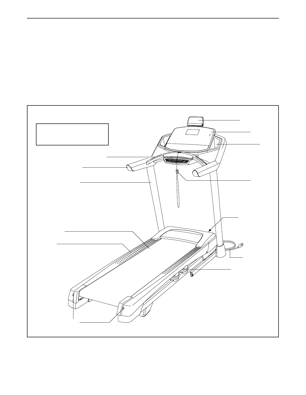
Length: 6 ft. 6 in. (198 cm)
Width: 3 ft. (91 cm)
Heart Rate Monitor
Handrail
Upright
reading this manual, please see the front cover of this
manual. To help us assist you, please note the product
model number and serial number before contacting us.
The model number and the location of the serial number decal are shown on the front cover of this manual.
Before reading further, please review the drawing
below and familiarize yourself with the labeled parts.
Tablet Holder
Console
Tray
Key/Clip
Walking Belt
Foot Rail
Idler Roller
Adjustment Screws
Power Switch
Power Cord
Platform Cushion
7
Page 8
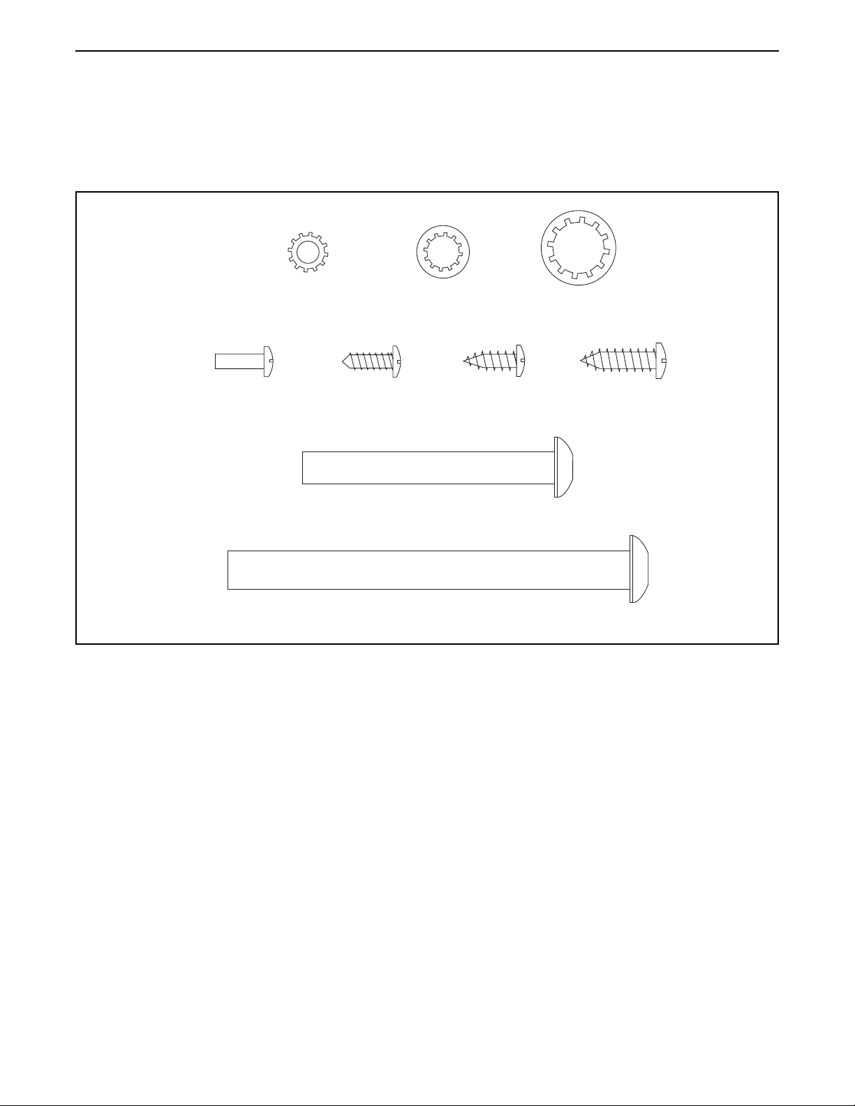
PART IDENTIFICATION CHART
Use the drawings below to identify small parts used for assembly. The number in parentheses below each drawing is the key number of the part, from the PART LIST near the end of this manual. The number following the key
number is the quantity used for assembly. Note: If a part is not in the hardware kit, check to see whether it is
pre-attached. Extra parts may be included.
#10 Star
Washer (5)–4
#8 x 1/2" Machine
Screw (115)–4
Washer (11)–10
#8 x 1/2" Silver
Screw (10)–1
5/16" x 2 1/2"
Screw (28)–4
3/8" x 4" Screw (7)–6
5/16" Star
#8 x 1/2"
Screw (1)–10
3/8" Star
Washer (13)–6
#10 x 3/4" Screw
(9)–4
8
Page 9
ASSEMBLY
• Assembly requires two persons.
• Place all parts in a cleared area and remove the
packing materials. Do not dispose of the packing
materials until you nish all assembly steps.
• After shipping, there may be an oily substance
on the exterior of the treadmill. This is normal. If
there is an oily substance on the treadmill, wipe
it off with a soft cloth and a mild, non-abrasive
cleaner.
• Left parts are marked “L” or “Left” and right parts
are marked “R” or “Right.”
1. Go to www.proformservice.com/
registration on your computer and register
your product.
• activates your warranty
• saves you time if you ever need to contact
Customer Care
• To identify small parts, see page 8.
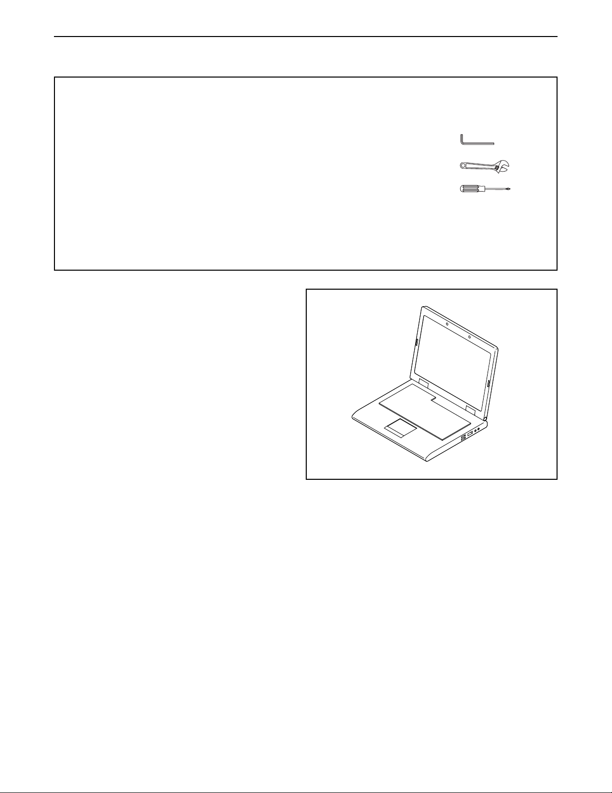
• Assembly requires the following tools:
the included hex key
one adjustable wrench
one Phillips screwdriver
To avoid damaging parts, do not use power tools.
1
• allows us to notify you of upgrades and offers
Note: If you do not have Internet access, call
Customer Care (see the front cover of this
manual) and register your product.
9
Page 10
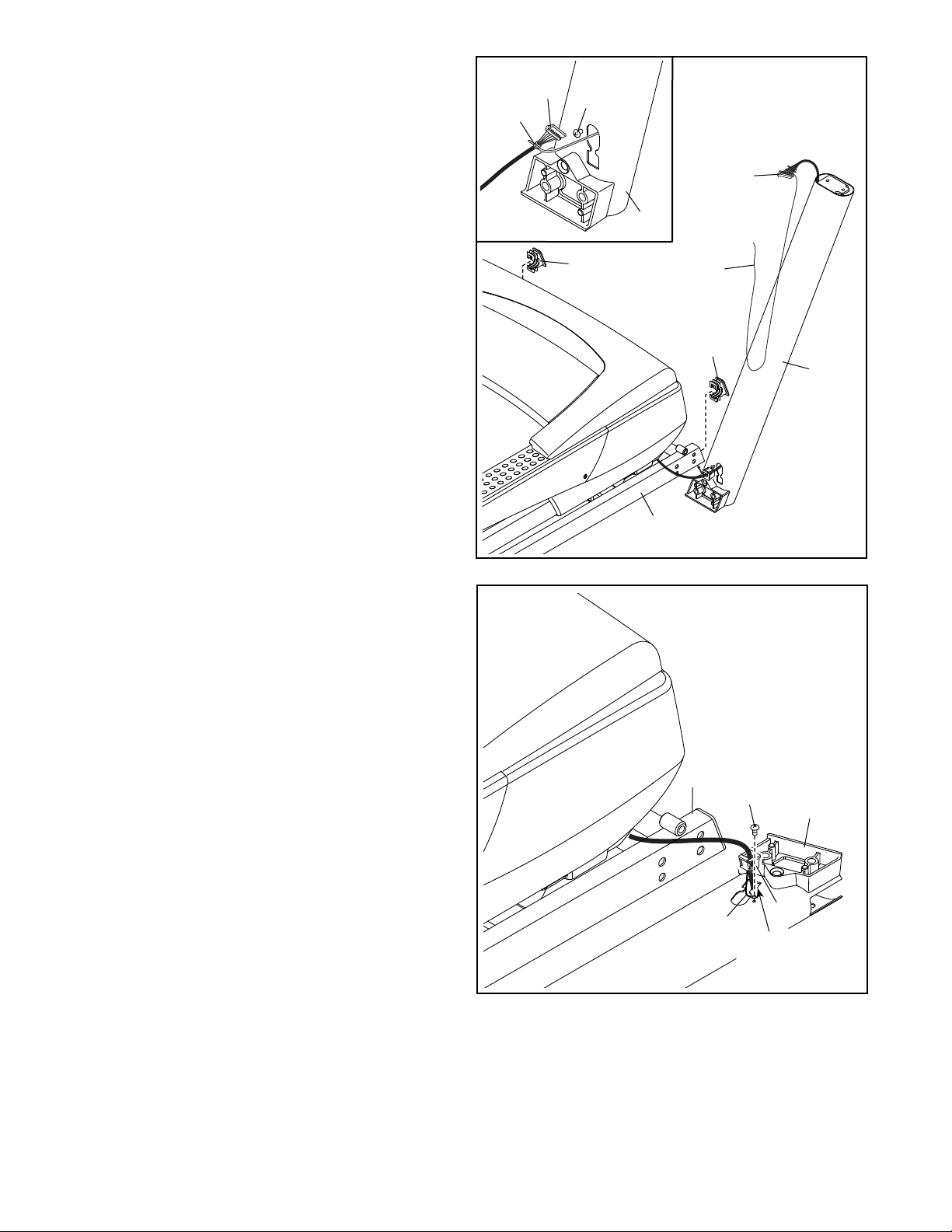
2. Make sure that the power cord is
unplugged.
Press a Base Cap (74) into each side of the
Base (94).
2
Wire
Tie
81
A
Remove the tie securing the Upright Wire (81) to
the front of the Base (94).
Identify the Right Upright (90). Have a second
person hold the Right Upright near the Base
(94).
See the inset drawing. Tie the wire tie in the
Right Upright (90) securely around the end of
the Upright Wire (81). Then, insert the Upright
Wire into the lower end of the Right Upright as
you pull the other end of the wire tie through the
Right Upright.
Then, remove and discard the indicated screw (A).
3. Lay the Right Upright (90) near the Base (94).
Press the Grommet (77) into the square hole in
the Right Upright. Make sure not to pinch the
ground wire.
81
90
74
3
Wire
Tie
74
90
94
Then, attach the ground wire to the Right Upright
(90) with a #8 x 1/2" Silver Screw (10) as shown.
94
Ground
Wire
10
90
77
Square
Hole
10
Page 11
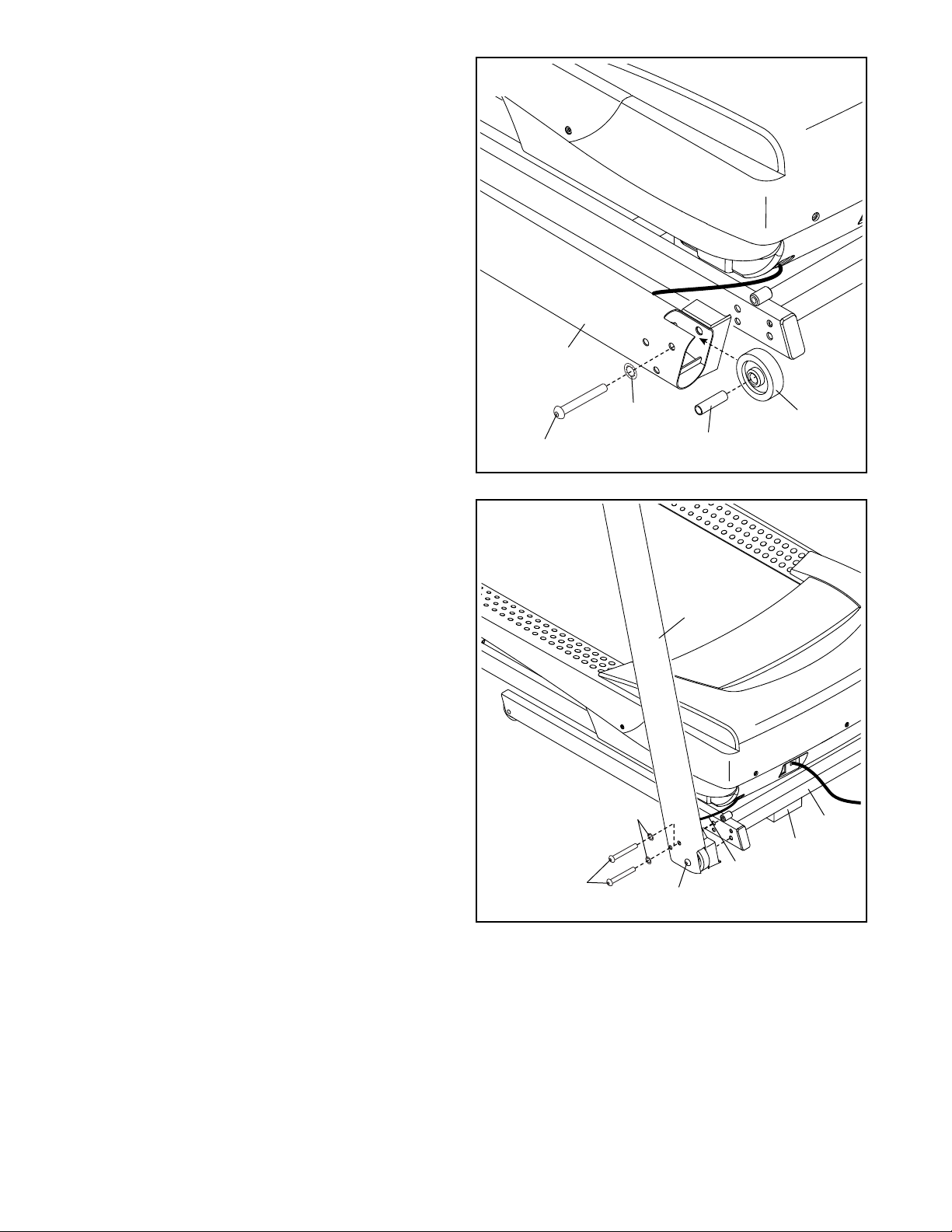
4. Insert a Wheel Spacer (63) into a Front Wheel
(62). Hold the Front Wheel inside the lower end
of the Right Upright (90), and insert a 3/8" x 4"
Screw (7) with a 3/8" Star Washer (13) into the
Right Upright and the Front Wheel.
Repeat this step on the other side of the
treadmill (not shown).
4
90
5. Place a piece of packing material (B) under
the right side of the Base (94). Hold the Right
Upright (90) against the Base. Make sure not
to pinch the Upright Wire (81).
Insert two 3/8" x 4" Screws (7) with two 3/8" Star
Washers (13) into the Right Upright (90), and
partially tighten the three Screws into the Base
(94); do not fully tighten the Screws yet.
Move the packing material (B) to the left side
of the Base (94) and attach the Left Upright
(not shown) in the same way. Note: There are
no wires on the left side.
Remove the packing material (B) from under-
neath the Base (94).
13
7
5
13
7
63
90
81
7
62
94
B
11
Page 12
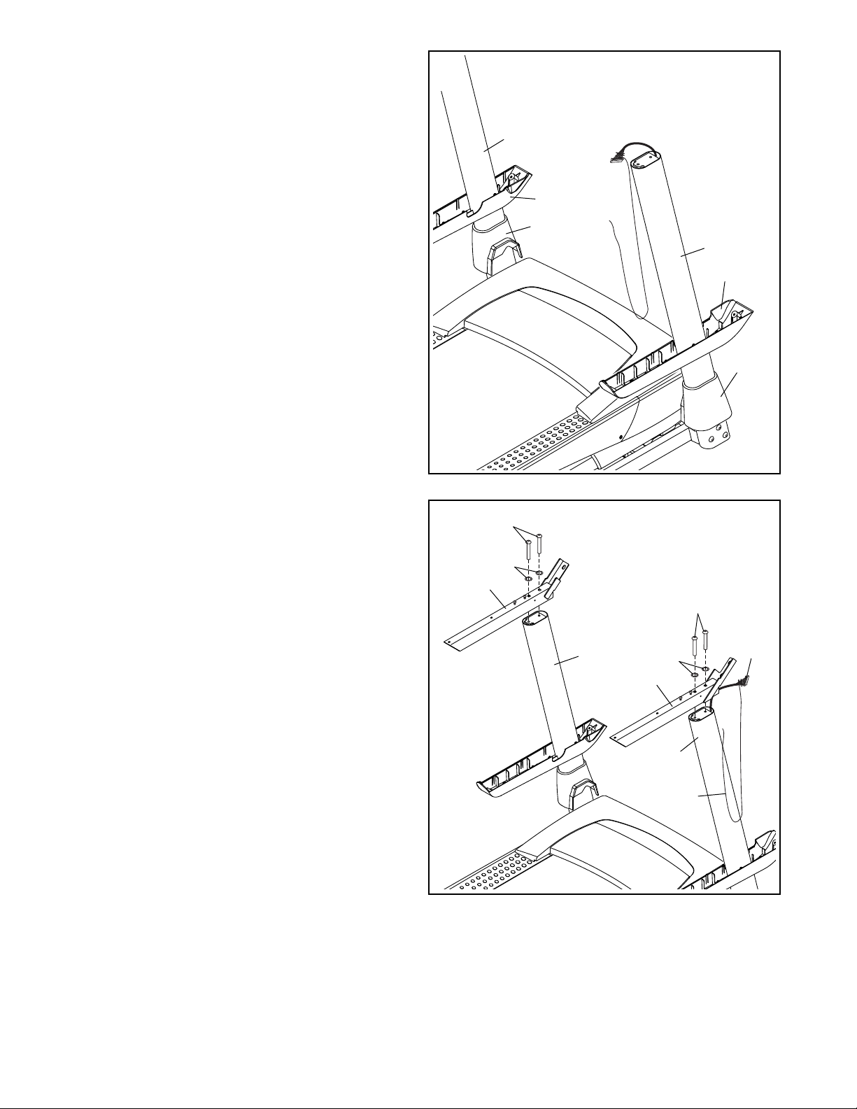
6. Identify the Left and Right Base Covers (82, 83).
Slide the Left Base Cover onto the Left Upright
(89), and slide the Right Base Cover onto the
Right Upright (90). Do not press the Base
Covers into place yet.
Identify the Right and Left Bottom Handrail
Covers (84, 85). Slide the Left Bottom Handrail
Cover onto the Left Upright (89), and slide the
Right Bottom Handrail Cover onto the Right
Upright (90).
6
89
85
82
90
84
83
7. Hold the Right Handrail (87) near the Right
Upright (90). Insert the Upright Wire (81) through
the Right Handrail as shown, and then remove
the wire tie from the Upright Wire.
Next, attach the Right Handrail (87) to the Right
Upright (90) with two 5/16" x 2 1/2" Screws (28)
and two 5/16" Star Washers (11). Make sure not
to pinch the Upright Wire (81). Firmly tighten
the Screws.
Then, attach the Left Handrail (86) to the Left
Upright (89) with two 5/16" x 2 1/2" Screws (28)
and two 5/16" Star Washers (11). Firmly tighten
the Screws. Note: There are no wires on the left
side.
7
86
28
11
89
87
11
90
Wire
Tie
28
81
12
Page 13
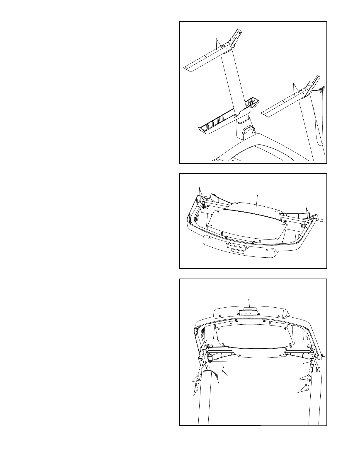
8. If there are four screws (C) in the locations
shown, remove and discard them.
8
C
C
9. Set the console assembly face down on a soft
surface to avoid scratching the console assembly. Remove and save the four 5/16" x 1/2"
Screws (4).
10. Set the console assembly on the Left and Right
Handrails (86, 87). Make sure not to pinch any
wires (D, 81).
Attach the console assembly with the four 5/16"
x 1/2" Screws (4) that you removed in step 9
and four 5/16" Star Washers (11); do not fully
tighten the Screws yet.
9
10
4
Console
Assembly
4
Console
Assembly
13
11
D
87
81
4
86
11
4
Page 14
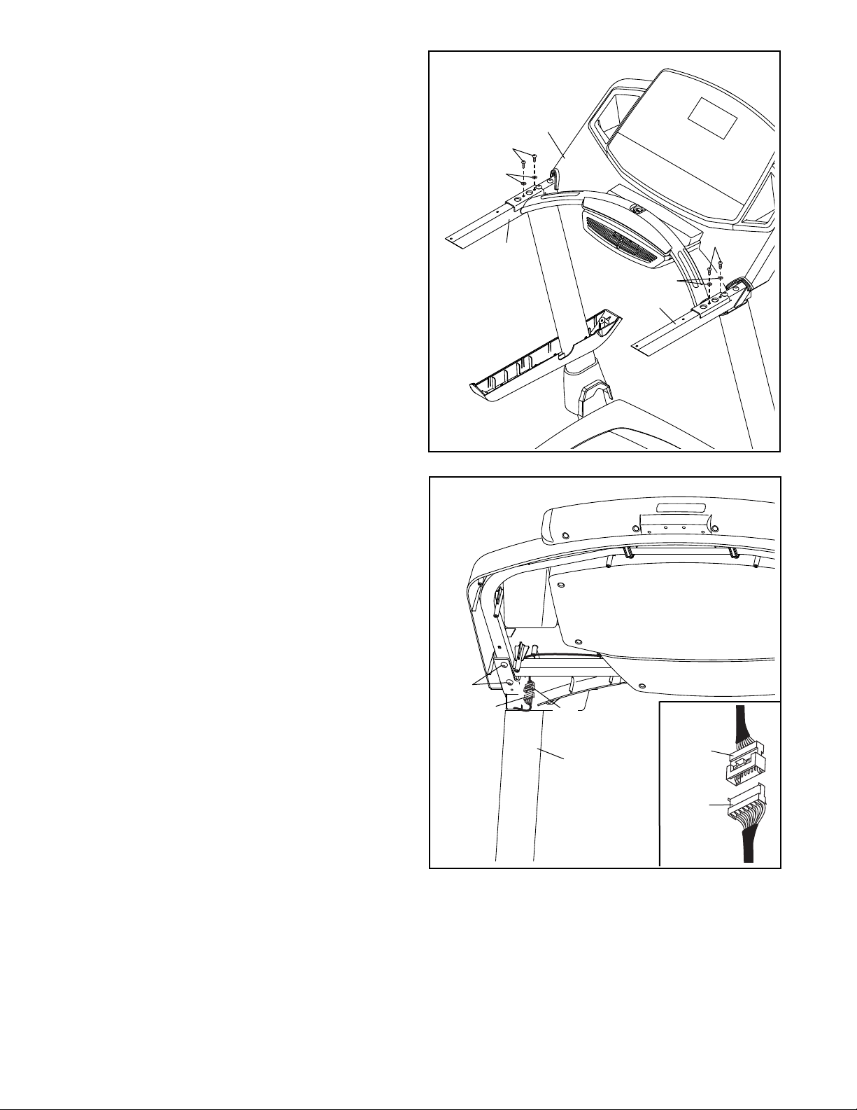
11. Attach the console assembly to the Handrails
(86, 87) with four #10 x 3/4" Screws (9) and four
#10 Star Washers (5) as shown; start all four
Screws, and then tighten them.
11
Console
Assembly
9
5
12. See the inset drawing. Connect the Upright
Wire (81) to the console wire (D). The connec-
tors should slide together easily and snap
into place. If they do not, turn one connector
and try again. IF YOU DO NOT CONNECT THE
CONNECTORS PROPERLY, THE CONSOLE
MAY BECOME DAMAGED WHEN YOU TURN
ON THE POWER.
Insert the excess wires (D, 81) into the Right
Upright (90).
12
86
9
5
87
Firmly tighten the four 5/16" x 1/2" Screws (4)
(only two are shown).
14
4
81
D
D
90
81
Page 15
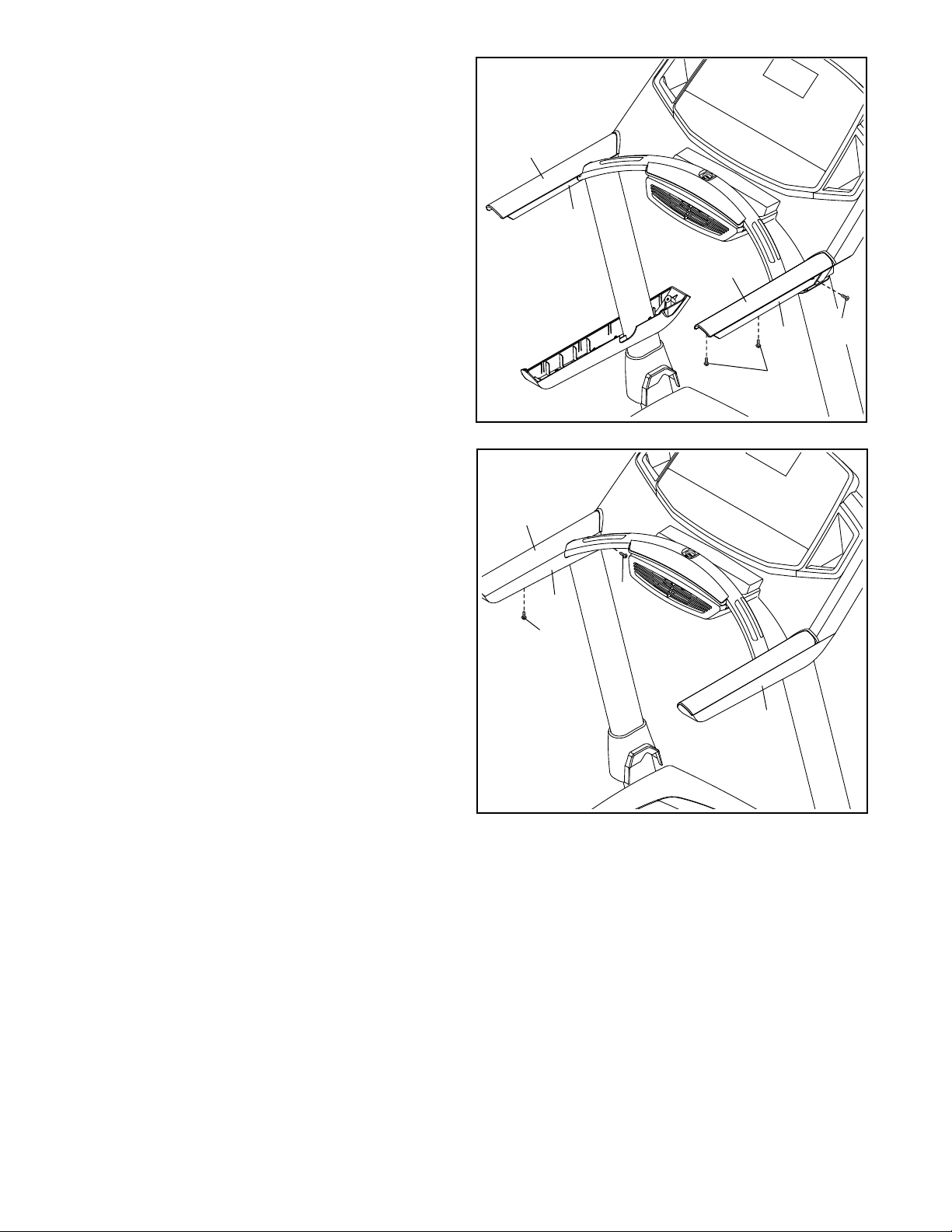
13. Attach the Right Handrail Cover (92) to the Right
Handrail (87) with three #8 x 1/2" Screws (1); do
not overtighten the Screws.
13
Attach the Left Handrail Cover (79) to the Left
Handrail (86) in the same way.
14. Slide the Left Bottom Handrail Cover (85)
up against the Left Handrail Cover (79), and
attach the Left Bottom Handrail Cover with two
#8 x 1/2" Screws (1); do not overtighten the
Screws.
Attach the Right Bottom Handrail Cover (84)
in the same way.
14
79
79
85
86
92
87
1
1
1
1
84
15
Page 16
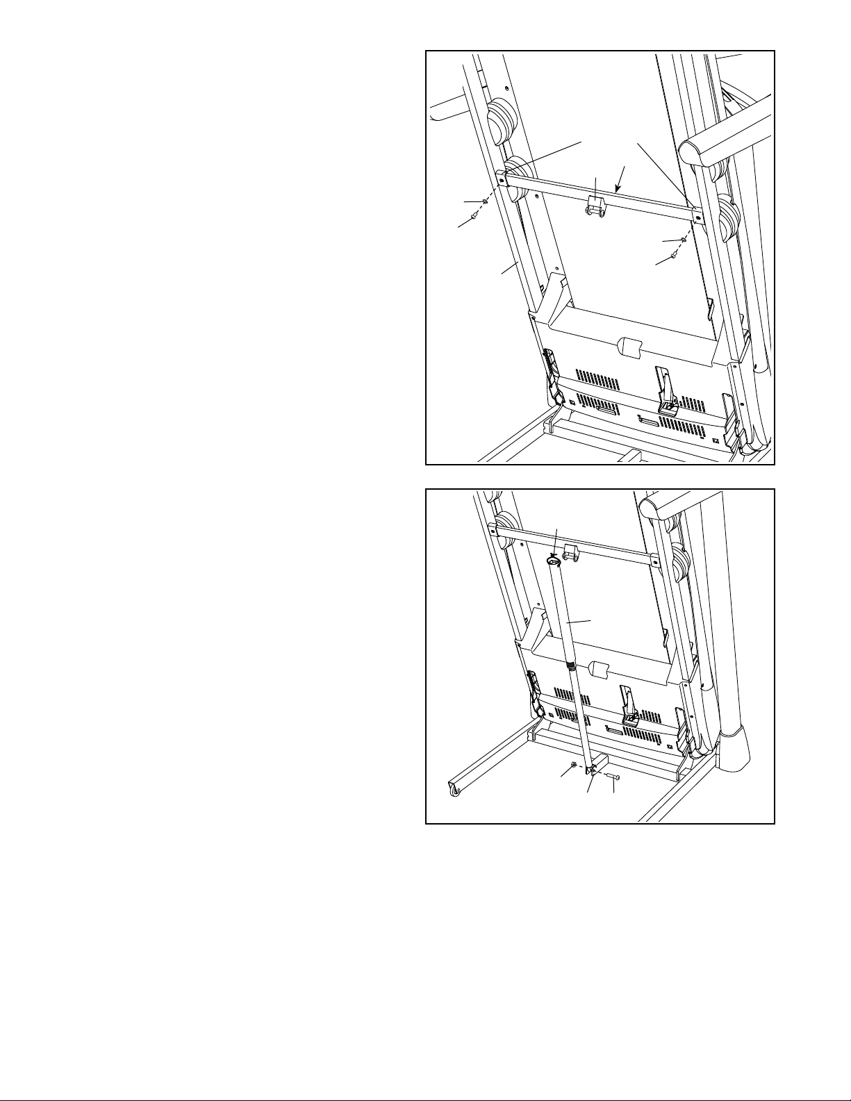
15. Note: If the treadmill is assembled on a
smooth surface, it may roll forward during
this step.
Raise the Frame (56) to the upright position.
IMPORTANT: Do not raise the Frame past the
vertical position. Have a second person hold
the Frame until step 17 is completed.
15
Brackets
E
38
Orient the Latch Crossbar (38) as shown. Make
sure that the “This side toward belt” sticker
(E) is facing the treadmill. Attach the Latch
Crossbar to the brackets on the Frame (56) with
two 5/16" x 3/4" Screws (25) and two 5/16" Star
Washers (11).
16. Remove the 5/16" Nut (12) and the 5/16" x 1 3/4"
Bolt (6) from the bracket on the Base (94).
Next, orient the Storage Latch (53) as shown.
Attach the lower end of the Storage Latch (53) to
the bracket on the Base (94) with a 5/16" x 1 3/4"
Bolt (6) and a 5/16" Nut (12).
16
25
11
11
25
56
Tie
53
Raise the Storage Latch (53) to a vertical posi-
tion. If there is a tie in the top of the Storage
Latch, remove and discard it.
12
94
6
16
Page 17
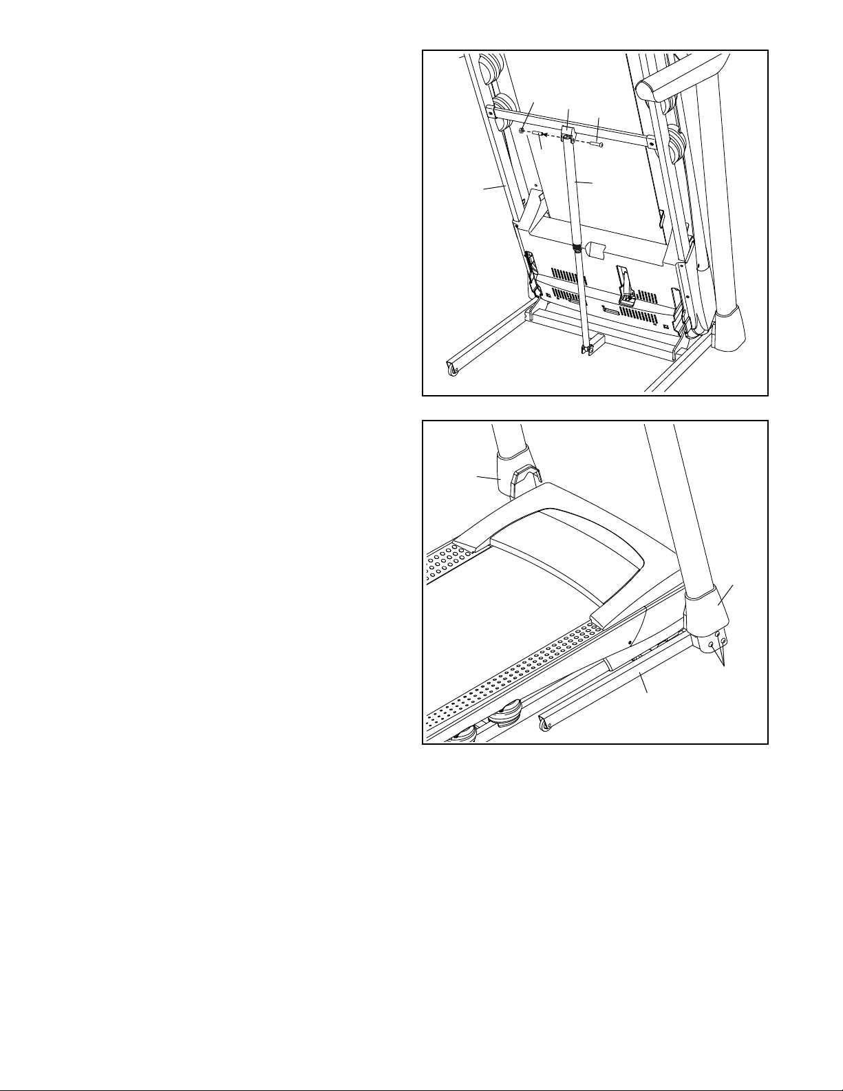
17. Remove the 5/16" Nut (12) and the 5/16" x 2 1/4"
Bolt (3) from the bracket on the Latch Crossbar
(38).
Align the upper end of the Storage Latch (53)
with the bracket on the Latch Crossbar (38),
and insert the 5/16" x 2 1/4" Bolt (3) through the
bracket and the Storage Latch. This will push a
spacer (F) out of the Storage Latch; discard
the spacer.
Next, tighten the 5/16" Nut (12) onto the 5/16" x
2 1/4" Bolt (3). Do not overtighten the Nut; the
Storage Latch (53) must be able to pivot.
Then, lower the Frame (56) (see HOW TO
LOWER THE TREADMILL FOR USE on page
29).
17
56
12
38
3
F
53
18. Firmly tighten the six 3/8" x 4" Screws (7)
(only one side is shown).
Press the Left Base Cover (82) and the Right
Base Cover (83) onto the Base (94).
18
82
83
7
94
17
Page 18
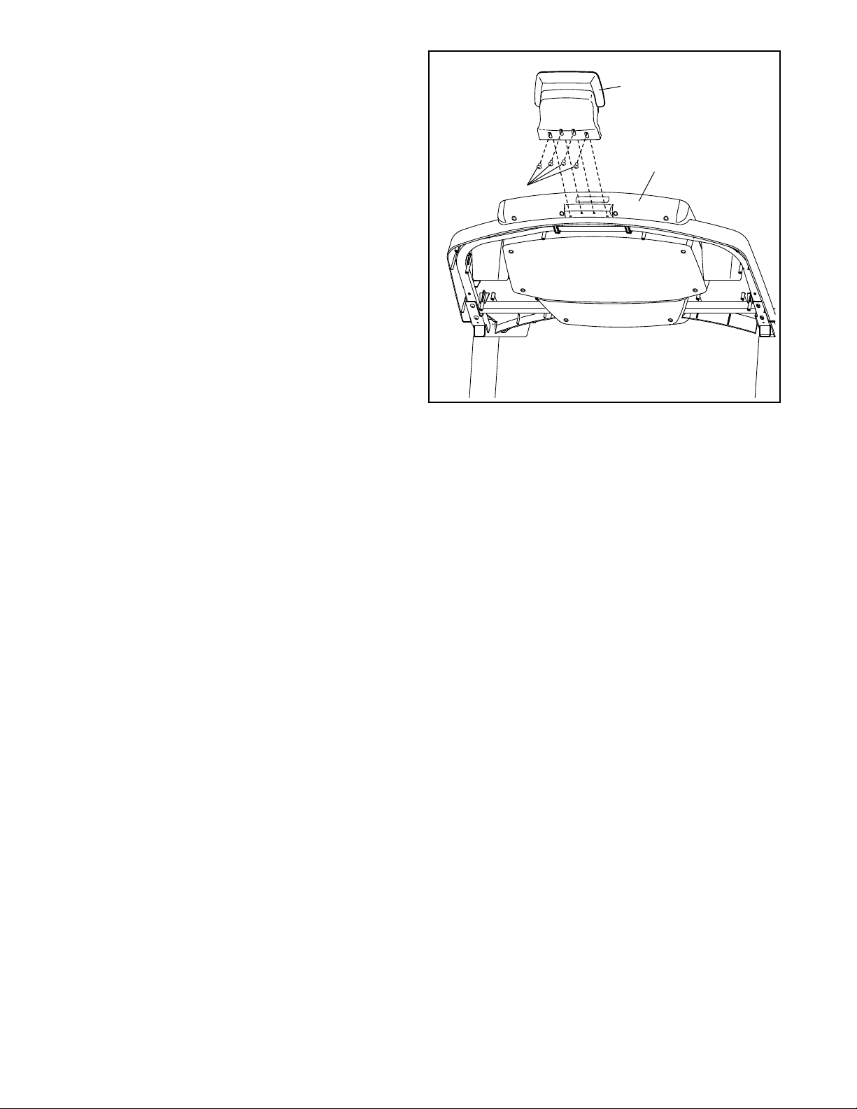
19. Attach the Tablet Holder (116) to the back of the
console assembly with four #8" x 1/2" Screws
(115); start all four Screws, and then tighten
them. Be careful not to overtighten the
Screws.
20. Make sure that all parts are properly tightened before you use the treadmill. If there are sheets of plastic
on the treadmill decals, remove the plastic. To protect the oor or carpet, place a mat under the treadmill. To
avoid damage to the console, keep the treadmill out of direct sunlight. Keep the included hex keys in a secure
place; one of the hex keys is used to adjust the walking belt (see pages 31 and 32). Note: Extra parts may be
included.
19
116
Console
Assembly
115
18
Page 19
HOW TO USE THE TREADMILL
HOW TO CONNECT THE POWER CORD
Use a Surge Suppressor
Your treadmill, like other electronic equipment, can be
damaged by sudden voltage changes in your home’s
power. Voltage surges, spikes, and noise interference can result from weather conditions or from other
appliances being turned on or off. To decrease the
risk of damaging the treadmill, always use a surge
suppressor with the treadmill. To purchase a surge
suppressor, see precaution 13 on page 3.
Use only a surge suppressor that is UL 1449 listed as a
transient voltage surge suppressor (TVSS). The surge
suppressor must have a UL suppressed voltage rating
of 400 volts or less and a minimum surge dissipation of
450 joules. The surge suppressor must also be electrically rated for 120 volts AC and 15 amps. There must
be a monitoring light on the surge suppressor to indicate whether it is functioning properly. Failure to use a
properly functioning surge suppressor could result
in damage to the control system of the treadmill
and serious injury to users.
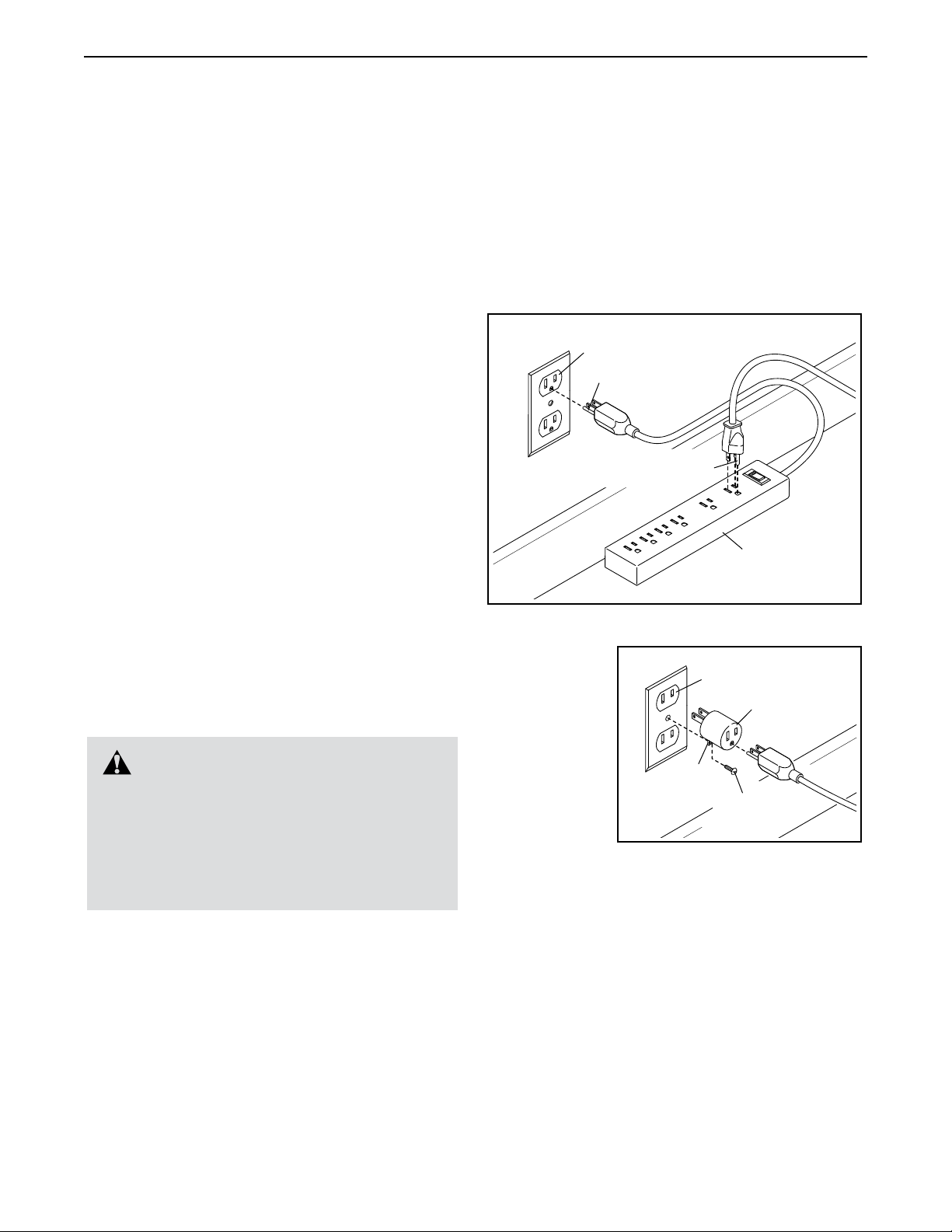
Plug in the Power Cord
nominal 120-volt circuit capable of carrying 15 or
more amps. To avoid overloading the circuit, do
not plug other electrical devices, except for lowpower devices such as cell phone chargers, into
the surge suppressor or into an outlet on the same
circuit. IMPORTANT: If the treadmill is connected to
an AFCI-equipped outlet and your circuit breaker
trips repeatedly when the treadmill is used, see the
front cover of this manual to purchase an arc filter.
1
Grounded Outlet
Grounding Pin
Grounding Pin
Surge
Suppressor
The treadmill must be grounded. If it should malfunction or break down, grounding provides a path of least
resistance for electric current to reduce the risk of electric shock. The treadmill power cord has a plug with a
grounding pin (see drawing 1 on this page).
DANGER: Improper connection
of the power cord increases the risk of electric shock. Do not modify the plug—if it will
not fit an outlet, have a proper outlet installed
by a qualified electrician. If you are unsure
whether the treadmill is properly grounded,
contact a qualified electrician.
Plug the power cord into a surge suppressor, and plug
the surge suppressor into an appropriate outlet that is
properly installed and grounded in accordance with all
local codes and ordinances. The outlet must be on a
A temporary
adapter may
be used to
connect the
surge suppressor to
a 2-pole
receptacle
if a properly
grounded
outlet is not
available.
The lug or wire extending from the adapter must
be connected with a metal screw to a permanent
ground such as a properly grounded outlet box cover.
Some 2-pole receptacle outlet box covers are not
grounded. Before using an adapter, contact a qualified electrician to determine whether the outlet box
cover is grounded. The temporary adapter should
be used only until a properly grounded outlet can
be installed by a qualified electrician.
2
2-pole Receptacle
Adapter
Lug
Metal
Screw
19
Page 20
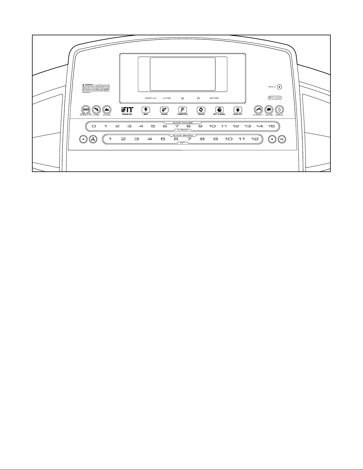
CONSOLE DIAGRAM
FEATURES OF THE CONSOLE
The treadmill console offers an impressive array of
features designed to make your workouts more effective and enjoyable. When you use the manual mode,
you can change the speed and incline of the treadmill
with the touch of a button. As you exercise, the console
will display instant exercise feedback. You can even
measure your heart rate using the handgrip heart rate
monitor.
In addition, the console features a selection of onboard
workouts. Each workout automatically controls the
speed and incline of the treadmill as it guides you
through an effective exercise session.
The console also features an iFit mode that enables
the treadmill to communicate with your wireless
network. With the iFit mode, you can download personalized workouts, create your own workouts, track
your workout results, race against other iFit users, and
access many other features.
You can even listen to your favorite workout music or
audio books with the console’s sound system while you
exercise.
To turn on the power, see page 21. To use the manual mode, see page 21. To use an onboard workout,
see page 23. To use a set-a-goal workout, see page
24. To use an iFit workout, see page 25. To use the
sound system, see page 26. To change console settings, see page 26.
IMPORTANT: If there are sheets of plastic on the
console, remove the plastic. To prevent damage
to the walking platform, wear clean athletic shoes
while using the treadmill. The rst time you use
the treadmill, observe the alignment of the walking
belt, and center the walking belt if necessary (see
page 32).
20
Page 21
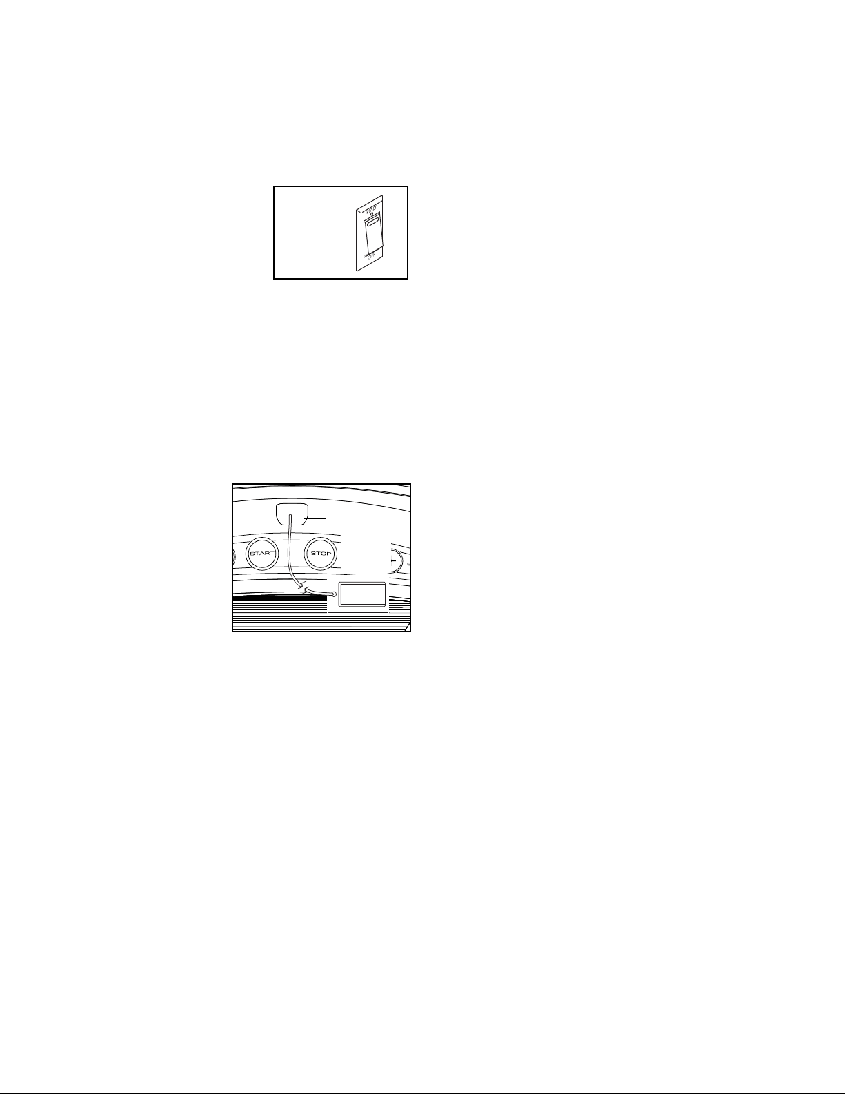
HOW TO TURN ON THE POWER
HOW TO USE THE MANUAL MODE
IMPORTANT: If the treadmill has been exposed to
cold temperatures, allow it to warm to room temperature before you turn on the power. If you do
not do this, you may damage the console displays
or other electrical components.
Plug in the power cord
(see page 19). Next, locate
the power switch on the
treadmill frame near the
power cord. Press the
power switch into the reset
position.
IMPORTANT: The console features a display demo
mode, designed to be used if the treadmill is displayed in a store. If the displays light as soon as
you plug in the power cord and press the power
switch into the reset position, the demo mode is
turned on. To turn off the demo mode, hold down
the Stop button for a few seconds. If the displays
remain lit, see HOW TO CHANGE CONSOLE
SETTINGS on page 26 to turn off the demo mode.
Next, stand on the
foot rails of the
treadmill. Find the
clip attached to the
key and slide the
clip onto the waistband of your clothes.
Then, insert the key
into the console.
After a moment, the
displays will light.
IMPORTANT: In an emergency, the key can be
pulled from the console, causing the walking belt
to slow to a stop. Test the clip by carefully taking
a few steps backward; if the key is not pulled from
the console, adjust the position of the clip.
IMPORTANT: Before you use the treadmill, take
the following steps to ensure that the console
shows the correct incline level of the treadmill:
First, press the Incline increase button once. Next,
press either the Incline decrease button or the lowest Quick Incline button to set the treadmill to its
lowest setting. When the frame stops moving, the
treadmill is ready for use.
Reset
Key
Clip
1. Insert the key into the console.
See HOW TO TURN ON THE POWER at the left.
2. Select the manual mode.
Press the Manual button on the console. If you
are not connected to iFit, the manual mode will be
selected automatically.
3. Start the walking belt.
To start the walking belt, press the Start button, the
Speed increase button, or one of the numbered
Quick Speed buttons.
If you press the Start button or the Speed increase
button, the walking belt will begin to move at 1
mph. As you exercise, change the speed of the
walking belt as desired by pressing the Speed
increase and decrease buttons. Each time you
press one of the buttons, the speed setting will
change by 0.1 mph; if you hold down the button,
the speed setting will change in increments of 0.5
mph. Note: After you press the button, it may take
a moment for the walking belt to reach the selected
speed setting.
If you press one of the numbered Quick Speed
buttons, the walking belt will gradually change
speed until it reaches the selected speed setting.
To select a speed setting that includes a decimal—
such as 3.5 mph—press two numbered buttons in
succession. For example, to select a speed setting
of 3.5 mph, press the 3 button and then immediately press the 5 button. Note: This will not function
if the console is set to metric units.
To stop the walking belt, press the Stop button. The
time will begin to flash in the display. To restart the
walking belt, press the Start button or the Speed
increase button.
21
Page 22
4. Change the incline of the treadmill as desired.
To change the incline of the treadmill, press the
Incline increase or decrease button or one of the
numbered Quick Incline buttons. Each time you
press one of the buttons, the treadmill will gradually
adjust to the selected incline setting.
5. Follow your progress with the displays.
As you walk or run on the treadmill, the display can
show the following workout information:
• The elapsed time
during that segment. Note: When you select
the Calorie tab, the calorie display will show the
approximate number of calories burned per hour.
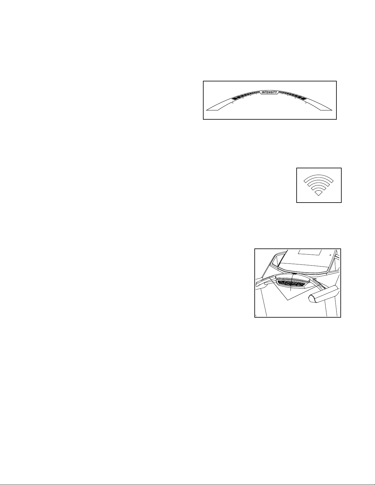
As you exercise, the workout intensity level bar will
indicate the approximate intensity level of your
exercise.
• The distance that you have walked or run
• The workout intensity bar
• The approximate number of calories you have
burned
• The incline level of the treadmill
• The number of vertical feet you have climbed
• The speed of the walking belt
• Your heart rate (see step 6)
• The matrix
The matrix offers several display tabs. Press the
increase and decrease buttons next to the Enter
button or press the Display button until the desired
tab is shown.
The Incline tab will show a prole of the incline set-
tings of the workout. A new segment will appear at
the end of each minute.
The Speed tab will show a prole of the speed set-
tings of the workout.
Press the Home button to return to the default
menu (see HOW TO CHANGE CONSOLE
SETTINGS on page 26 to set the default menu). If
necessary, press the Home button again.
The wireless symbol at the
top of the display will show
the strength of your wireless
signal. Four arcs indicate full
signal strength.
To reset the displays, press the Stop button, re-
move the key, and then reinsert the key.
6. Measure your heart rate if desired.
Before using
the handgrip heart
rate monitor,
remove the
sheets of plastic from the
metal contacts
on the pulse
bar. In addition, make
sure that your hands are clean.
Contacts
The My Trail tab will show a track that represents
1/4 mile (400 m). As you exercise, the ashing
rectangle will show your progress. The My Trail tab
will also show the number of laps you complete.
The Calorie tab will show the approximate amount
of calories you have burned. The height of each
segment represents the amount of calories burned
To measure your heart rate, stand on the foot
rails and hold the pulse bar with your palms on the
metal contacts; avoid moving your hands. When
your pulse is detected, several dashes will appear
and then your heart rate will be shown. For the
most accurate heart rate reading, continue to
hold the contacts for about 15 seconds.
22
Page 23
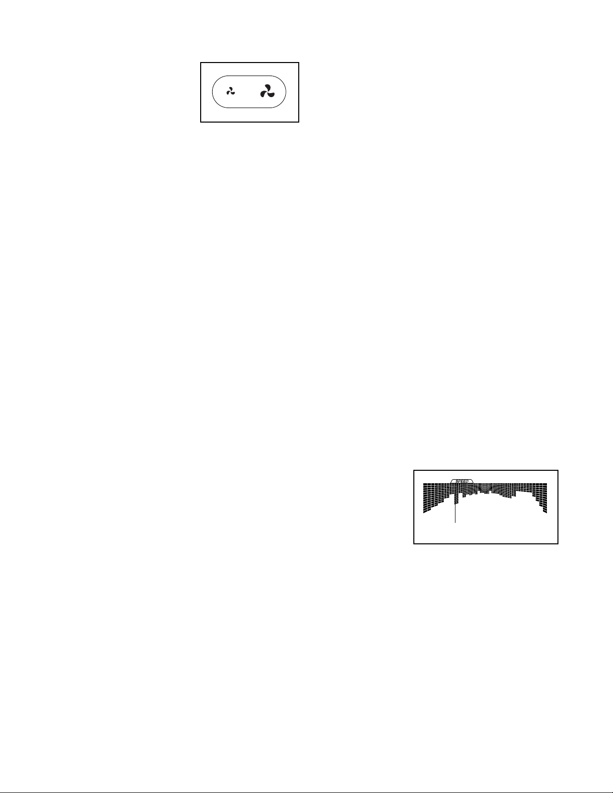
7. Turn on the fan if desired.
HOW TO USE AN ONBOARD WORKOUT
The fan features multiple
speed settings. Press
the fan increase or decrease button to select a
fan speed or to turn off
the fan. Note: If the fan
is on when the walking
belt is stopped, the fan will turn off automatically
after a few minutes.
8. When you are finished exercising, remove the
key from the console.
Step onto the foot rails, press the Stop button, and
adjust the incline of the treadmill to zero. The
incline must be zero or you may damage the
treadmill when you fold it to the storage position. Next, remove the key from the console and
put it in a secure place.
When you are finished using the treadmill, press
the power switch into the off position and unplug
the power cord. IMPORTANT: If you do not do
this, the treadmill’s electrical components may
wear prematurely.
1. Insert the key into the console.
See HOW TO TURN ON THE POWER on page 21.
2. Select an onboard workout.
To select an onboard workout, press the Speed
button, the Incline button, the Intensity button,
or the Calorie button repeatedly until the desired
workout appears in the display.
When you select an onboard workout, the displays
will show the maximum incline, the duration, the
distance, the maximum speed, and the name of the
workout. In addition, a prole of the speed settings
of the workout will appear in the matrix. If you select a calorie workout, the approximate number of
calories you will burn will appear in the name of the
workout.
3. Start the workout.
Press the Start button or the Speed increase button
to start the workout. A moment after you press the
button, the treadmill will automatically adjust to the
first speed and incline settings of the workout. Hold
the handrails and begin walking.
Each workout is divided into segments. One speed
setting and one incline setting are programmed for
each segment. Note: The same speed setting and/
or incline setting may be programmed for consecutive segments.
During the
workout, the
prole will
show your
progress.
The ashing segment
of the prole
represents the current segment of the workout. The
height of the ashing segment indicates the approximate speed setting for the current segment.
At the end of each segment, a series of tones will
sound and the next segment of the prole will begin
to ash. If a new speed and/or incline setting is
programmed for the next segment, the new speed
and/or incline setting will appear in the displays for
a few seconds and the treadmill will automatically
adjust to the new speed and/or incline setting.
Current Segment
23
Page 24

The workout will continue in this way until the last
segment of the prole ashes in the display and the
last segment ends. The walking belt will then slow
to a stop.
Note: The calorie goal is an estimate of the
number of calories that you will burn during
the workout. The actual number of calories
that you burn will depend on various factors
such as your weight. In addition, if you manually change the speed or incline of the treadmill
during the workout, the number of calories you
burn will be affected.
If the speed or incline setting is too high or too low
at any time during the workout, you can manually override the setting by pressing the Speed or
Incline buttons; however, when the next segment
of the workout begins, the treadmill will automatically adjust to the speed and incline settings for the next segment.
HOW TO USE A SET-A-GOAL WORKOUT
1. Insert the key into the console.
See HOW TO TURN ON THE POWER on page 21.
2. Select a set-a-goal workout.
To select a calorie, time, or distance set-a-goal
workout, press the Set A Goal button on the console repeatedly.
Next, press the increase and decrease buttons
next to the Enter button to select a goal. Press
the Speed and Incline buttons to select the speed
and incline for the workout. The screen will show
the duration and distance of the workout, and the
approximate number of calories you will burn during the workout.
3. Start the workout.
To stop the workout at any time, press the Stop
button. The time will begin to flash in the display.
To resume the workout, press the Start button or
the Speed increase button. The walking belt will
begin to move at 1 mph. When the next segment of
the workout begins, the treadmill will automatically
adjust to the speed and incline settings for the next
segment.
4. Follow your progress with the displays.
See step 5 on page 22.
5. Measure your heart rate if desired.
See step 6 on page 22.
6. Turn on the fan if desired.
See step 7 on page 23.
7. When you are finished exercising, remove the
key from the console.
See step 8 on page 23.
Press the Start button to start the workout. A
moment after you press the button, the walking belt
will begin to move. Hold the handrails and begin
walking.
The workout will function in the same way as the
manual mode (see pages 21 to 23).
The workout will continue until you reach the goal
that you set. The walking belt will then slow to a
stop.
Note: The calorie goal is an estimate of the
number of calories that you will burn during the
workout. The actual number of calories that you
burn will depend on various factors such as
your weight.
4. Follow your progress with the displays.
See step 5 on page 22.
5. Measure your heart rate if desired.
See step 6 on page 22.
6. Turn on the fan if desired.
See step 7 on page 23.
7. When you are finished exercising, remove the
key from the console.
See step 8 on page 23.
24
Page 25

HOW TO USE AN IFIT WORKOUT
5. Start the workout.
Note: To use an iFit workout, you must have access
to a wireless network (see page 26). An iFit account is
also required. Go to www.iFit.com to register for an
iFit account.
1. Insert the key into the console.
See HOW TO TURN ON THE POWER on page
21.
2. Select the iFit mode.
Press the Home button repeatedly to select the iFit
mode. The iFit welcome message will appear in the
display.
3. Select a user.
Press the home button to view the user selection
screen. Use the increase and decrease buttons
next to the Enter button to select a user.
4. Select an iFit workout.
To select an iFit workout, press one of the iFit but-
tons. Before some workouts will download, you
must add them to your schedule on www.iFit.com.
See step 3 on page 23.
During some workouts, an audio coach may guide
you through your workout. You can select a setting for your audio coach (see HOW TO CHANGE
CONSOLE SETTINGS on page 26).
To stop the workout at any time, press the Stop
button. The time will begin to ash in the display.
To resume the workout, press the Start button or
the Speed increase button. The walking belt will
begin to move at the speed setting for the rst segment of the workout. When the next segment of
the workout begins, the treadmill will automatically
adjust to the speed and incline settings for the next
segment.
6. Follow your progress with the displays.
See step 5 on page 22.
During a competition workout, the Compete tab
will show your progress in the race. As you race,
the top line in the matrix will show how much of the
race you have completed. The other lines will show
your top four competitors. The end of the matrix
represents the end of the race.
To download an iFit workout in your schedule,
press the iFit button to download the next workout
in your schedule. Press the Map, Train, or Lose Wt.
button to download the next workout of that type in
your schedule. To compete in a race that you have
previously scheduled, press the Compete button.
To re-run a recent iFit workout from your schedule,
first press the Track button. Next, press the increase and decrease buttons to select the desired
workout. Then, press the Enter button to start the
workout.
Note: Before some workouts will download, you
must add them to your schedule on iFit.com.
For more information about the iFit workouts,
please see www.iFit.com.
When you select an iFit workout, the display will
show the duration of the workout, the distance you
will walk or run, and the approximate number of
calories you will burn. The display may also show
the name of the workout.
7. Measure your heart rate if desired.
See step 6 on page 22.
8. Turn on the fan if desired.
See step 7 on page 23.
9. When you are finished exercising, remove the
key from the console.
See step 8 on page 23.
For more information about the iFit mode, go to
www.iFit.com.
IMPORTANT: To satisfy exposure compliance
requirements, the antenna and transmitter in the
console must be at least 8 in. (20 cm) from all
persons and must not be near or connected to any
other antenna or transmitter.
25
Page 26

HOW TO USE THE SOUND SYSTEM
To play music or audio books through the console
sound system while you exercise, plug a 3.5 mm male
to 3.5 mm male audio cable (not included) into the jack
on the console and into a jack on your MP3 player,
CD player, or other personal audio player; make sure
that the audio cable is fully plugged in. Note: To
purchase an audio cable, see your local electronics
store.
Next, press the play button on your personal audio
player. Adjust the volume
level using the volume
increase and decrease
buttons on the console or
the volume control on your
personal audio player.
If you are using a personal CD player and the CD
skips, set the CD player on the oor or another at
surface instead of on the console.
The lower section of the display will show instruc-
tions for the selected optional screen. Make sure
to follow the instructions shown in the lower
part of the display.
3. Change settings as desired.
Demo—The console features a display demo
mode, designed to be used if the treadmill is displayed in a store. While the demo mode is turned
on, the console will function normally when you
plug in the power cord, press the power switch
into the reset position, and insert the key into the
console. However, when you remove the key, the
displays will remain lit, although the buttons will not
function. If the demo mode is turned on, the word
ON will appear in the matrix. To turn on or turn off
the demo mode, press the Enter button.
Units—The selected unit of measurement will
appear in the matrix. To change the unit of measurement, press the Enter button. To view distance
in miles, select ENGLISH. To view distance in
kilometers, select METRIC.
HOW TO CHANGE CONSOLE SETTINGS
The console features a settings mode that allows you
to view usage information, to personalize console settings, and to set up and manage a wireless network
connection.
1. Select the settings mode.
To select the settings mode, hold down the Stop
button while inserting the key into the console and
then release the Stop button. The settings mode
will then appear in the display.
The time display will show the total number of
hours that the treadmill has been used.
The distance display will show the total number
of miles (or kilometers) that the walking belt has
moved.
2. Navigate the settings mode menu.
While the settings mode is selected, the matrix
will display several optional screens. Press the
decrease button next to the Enter button to select
each of the optional screens.
Default Menu—The default menu will appear when
you insert the key into the console or when you
press the Home button. Press the Enter button
repeatedly to select the manual main screen or the
iFit screen as the default menu.
Firmware Update—For the best results,
regularly check for firmware updates.
Note: The matrix will display NOT CONNECTED if
the console is not connected to a wireless network.
Press the Enter button to check for firmware
updates using your wireless network. If an update
is available, the update will begin automatically.
IMPORTANT: To avoid damaging the treadmill,
do not turn off the power while the firmware is
being updated. The update may take several
minutes.
Note: Occasionally, a firmware update may cause
your console to function slightly differently. These
updates are always designed to improve your exercise experience.
Default Settings—To restore the console to its
factory default settings, press the Enter button.
Note: The console will erase any information that
you have saved in its memory.
26
Page 27
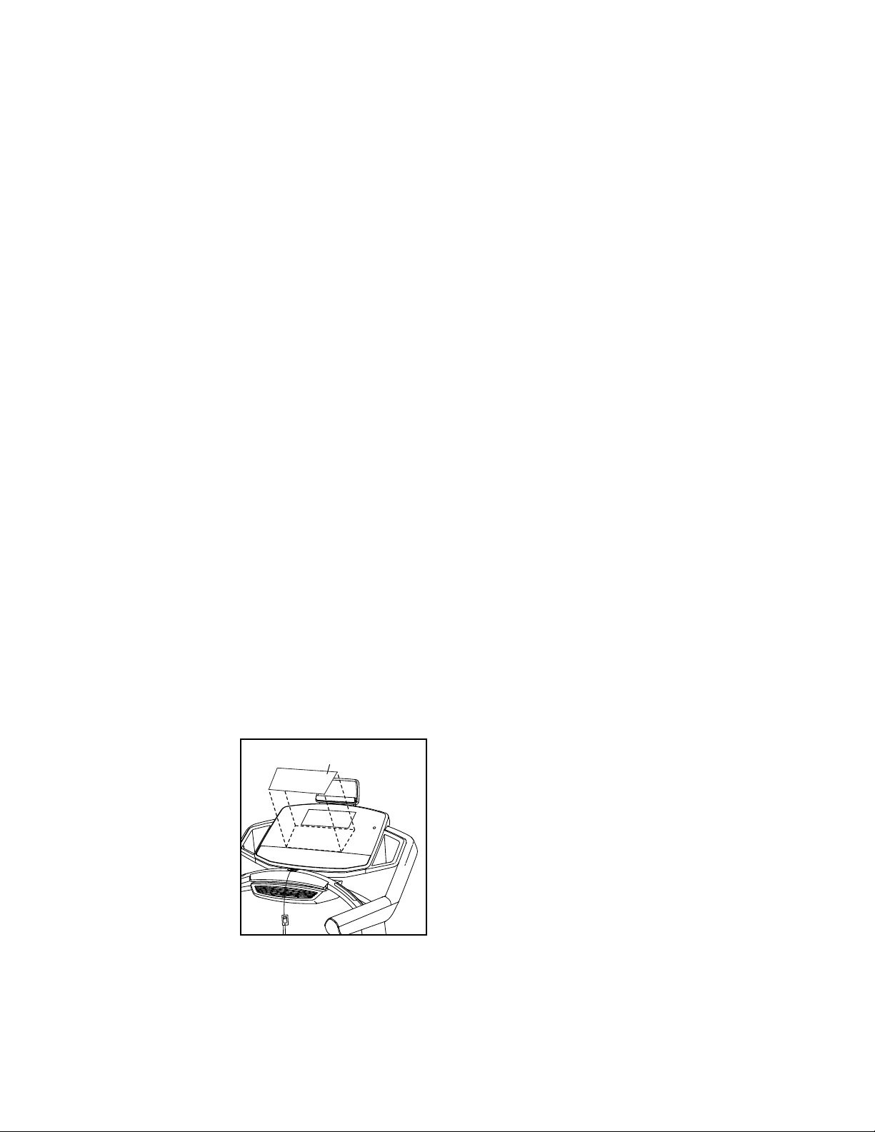
The WiFi–Normal option will allow you to set up
a wireless network connection using the console.
See step 4 for instructions.
The WiFi–WPS option will allow you to set up
a wireless network connection using your WPS
router. See step 5 for instructions.
The WiFi–Advanced option will allow you to set up
a wireless network connection using your computer, smart phone, tablet, or other Wi-Fi device.
See step 6 for instructions.
Connect to iFit Account—To set up a different iFit
account, but maintain the existing wireless connection, follow the instructions in the matrix.
Note: This option will rarely be used.
Clear WiFi Setting—To erase the console’s
wireless network settings and have it forget the
currently selected wireless network, follow the
instructions in the matrix.
A list of networks will appear in the matrix. Press
the up and down buttons to highlight the desired
network. Then, press the Enter button. Note: Do
not select IFIT_SETUP.
Note: The time display will show the number of
the currently-selected access point. The distance
display will show the total number of access points
detected.
If the network has a password, enter the password.
A keyboard will appear in the matrix. As necessary,
press the buttons on the WiFi setup card to select
the caps option, the number option, or the symbol
option.
Press the up, down, left, and right buttons to high-
light the desired letter or number. Then, press the
Enter button to select the letter, number, or symbol.
When you have finished entering the password,
press the Done button.
Contrast—To adjust the contrast level of the
display, press the Incline increase and decrease
buttons.
4. Use WiFi–Normal to set up a wireless
connection.
This option will allow you to set up a wireless net-
work connection using the console.
Note: You will need to know your network name
(SSID). If your network has a password, you will
also need to know the password.
To set up a wireless network connection using the
console, first press the Enter button.
Next, set the
included WiFi
setup card on
the console.
The buttons
on the WiFi
setup card are
referenced in
the following
instructions.
Card
A numerical code and a web address will appear in
the matrix. Go to the web address on your internetcompatible device.
Log in to your iFit account on the web page. Then,
enter the numerical code into the indicated field.
Follow any other instructions on the web page.
When the console is connected to a wireless
network, the wireless symbol in the display will
stop flashing and become solid. The wireless symbol will show the strength of your wireless signal;
four arcs indicate full signal strength.
If you cannot complete any part of this
process, or if you have any questions, go to
support.ifit.com for assistance.
5. Use WiFi–WPS to set up a wireless connection.
This option will allow you to set up a wireless net-
work connection using your WPS router.
To set up a wireless network connection using your
WPS router, first press the Enter button and follow
the instructions in the matrix.
A numerical code and a web address will appear in
the matrix. Go to the web address on your internetcompatible device.
27
Page 28
Log in to your iFit account on the web page. Then,
enter the numerical code into the indicated field.
Follow any other instructions on the web page.
If you cannot complete any part of this
process, or if you have any questions, go to
support.ifit.com for assistance.
When the console is connected to a wireless
network, the wireless symbol in the display will
stop flashing and become solid. The wireless symbol will show the strength of your wireless signal;
four arcs indicate full signal strength.
If you cannot complete any part of this
process, or if you have any questions, go to
support.ifit.com for assistance.
6. Use WiFi–Advanced to set up a wireless
connection.
This option will allow you to set up a wireless
network connection using your computer, smart
phone, tablet, or other Wi-Fi device.
On your computer, smart phone, tablet, or other
Wi-Fi device, open the list of available networks
to which your device can connect. One of the
options will be IFIT_SETUP; select this network. If
this network does not appear, make sure that your
Wi-Fi device is within range of the console, and
then close and re-open your list of networks. Also,
see Clear WiFi Setting on page 27 and clear any
previous wireless network settings on the console.
7. Exit the settings mode.
To exit the settings mode, remove the key from the
console.
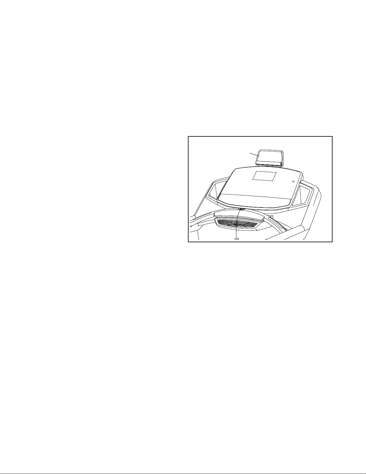
HOW TO USE THE TABLET HOLDER
You can use your tablet to browse media while you
exercise. Place your tablet on the tablet holder and let
the tablet holder hold your tablet in place.
Tablet
Holder
Note: The network IFIT_SETUP will not appear
if the console has already been configured to
connect to a wireless network.
The console will display an IP address, such as
192.168.0.1:8080. Open a web browser on your
computer, smart phone, tablet, or other Wi-Fi
device. Next, type in the IP address on the console into the URL bar in your browser. Example:
http://192.168.0.1:8080.
Your browser will load a web page. If the web page
does not appear, double-check the IP address and
the previous instructions of this step. Follow the
instructions on the web page to connect the treadmill to your wireless network.
Note: A warning may appear stating that the server
cannot be identified. If this happens, make sure
that you have entered the IP address correctly.
28
Page 29
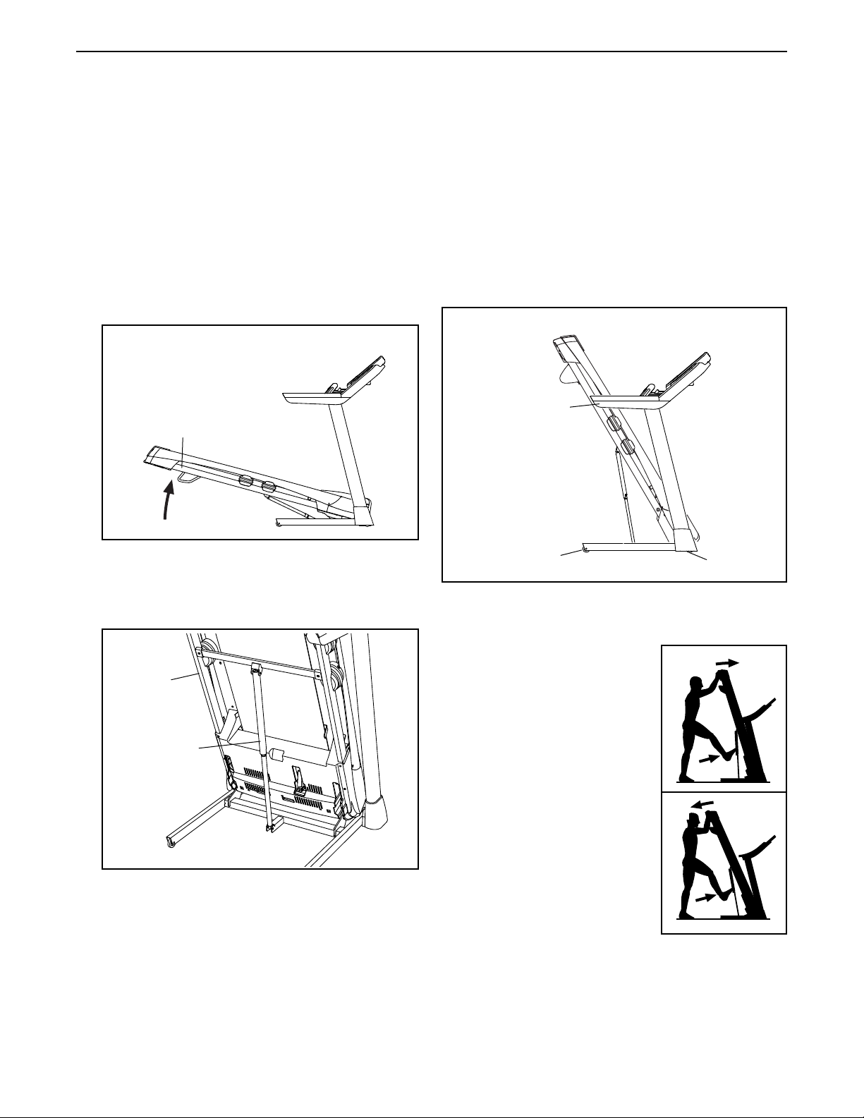
HOW TO FOLD AND MOVE THE TREADMILL
HOW TO FOLD THE TREADMILL
To avoid damaging the treadmill, adjust the incline
to zero before you fold the treadmill. Then, remove
the key and unplug the power cord.
CAUTION: You must be able to safely lift 45 lbs. (20
kg) to raise, lower, or move the treadmill.
1. Hold the metal frame rmly in the location shown
by the arrow below. CAUTION: Do not hold the
frame by the plastic foot rails. Bend your legs
and keep your back straight.
1
Frame
HOW TO MOVE THE TREADMILL
Before moving the treadmill, fold it as described at the
left. CAUTION: Make sure that the storage latch is
locked in the storage position. Moving the treadmill
may require two people.
Hold the handrails with both hands and carefully push
the treadmill to the desired location. CAUTION: Do not
pull on the frame, and do not move the treadmill
over an uneven surface.
Handrail
2. Raise the frame until the storage latch locks in the
storage position. CAUTION: Make sure that the
storage latch locks.
2
Frame
Latch
To protect the oor or carpet, place a mat under the
treadmill. Keep the treadmill out of direct sunlight.
Do not leave the treadmill in the storage position in
temperatures above 85° F (30° C).
Wheel
HOW TO LOWER THE TREADMILL FOR USE
1. Push the upper end of the
frame forward, and gently
press the upper part of the
storage latch with your foot
at the same time.
2. While pressing the storage
latch with your foot, pull
the upper end of the frame
toward yourself.
3. Step back and let the
frame lower to the floor.
Wheel
1
2
29
Page 30
MAINTENANCE AND TROUBLESHOOTING
MAINTENANCE
Regularly clean the treadmill and keep the walking
belt clean and dry. First, press the power switch into
the off position and unplug the power cord. Wipe
exterior parts of the treadmill with a damp cloth and a
small amount of mild soap. IMPORTANT: Do not spray
liquids directly onto the treadmill. To avoid damage
to the console, keep liquids away from the console.
Then, thoroughly dry the treadmill with a soft towel.
TROUBLESHOOTING
Most treadmill problems can be solved by following
the simple steps below. Find the symptom that
applies, and follow the steps listed. If further assistance is needed, see the front cover of this manual.
SYMPTOM: The power does not turn on
a. Make sure that the power cord is plugged into a
surge suppressor, and that the surge suppressor
is plugged into a properly grounded outlet (see
page 19). Use only a surge suppressor that meets
all of the specications described on page 18.
IMPORTANT: If the treadmill is connected to an
AFCI-equipped outlet and your circuit breaker
trips repeatedly when the treadmill is used, see
the front cover of this manual to purchase an
arc lter.
SYMPTOM: The power turns off during use
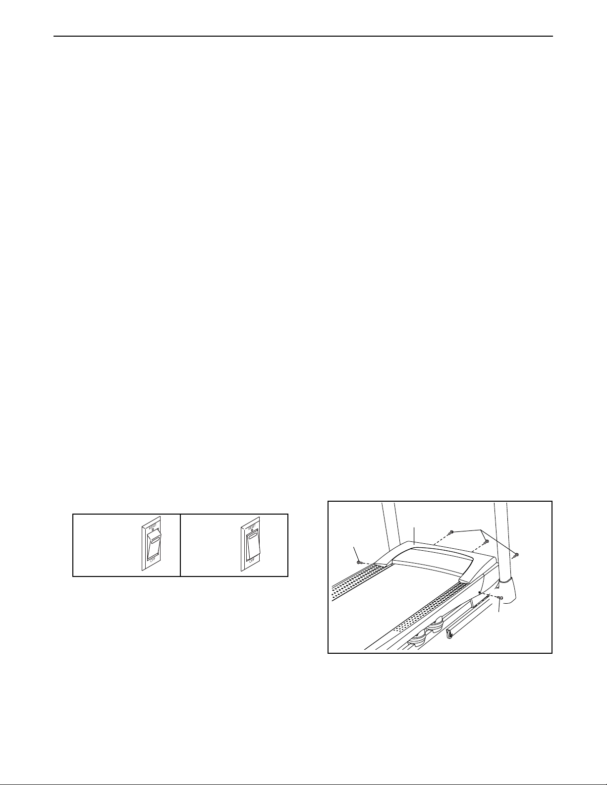
a. Check the power switch (see drawing c at the left).
If the switch has tripped, wait for ve minutes and
then press the switch back in.
b. Make sure that the power cord is plugged in. If the
power cord is plugged in, unplug it, wait for ve
minutes, and then plug it back in.
c. Remove the key from the console, and then
reinsert it.
d. If the treadmill still will not run, please see the front
cover of this manual.
SYMPTOM: The console displays remain lit when
you remove the key from the console
a. The console features a display demo mode,
designed to be used if the treadmill is displayed in
a store. If the displays remain lit when you remove
the key, the demo mode is turned on. To turn off
the demo mode, hold down the Stop button for a
few seconds. If the displays are still lit, see HOW
TO CHANGE CONSOLE SETTINGS on page 26 to
turn off the demo mode.
SYMPTOM: The displays of the console do not
function properly
b. After the power cord has been plugged in, make
sure that the key is inserted into the console.
c. Check the power switch located on the treadmill
frame near the power cord. If the switch protrudes
as shown, the switch has tripped. To reset the
c
Tripped
power switch, wait for ve minutes and then press
the switch back in.
Reset
a. Remove the key from the console and UNPLUG
THE POWER CORD. Remove the ve #8 x 3/4"
Tek Screws (14). Carefully pivot off the Motor Hood
(65).
a
65
14
14
14
30
Page 31
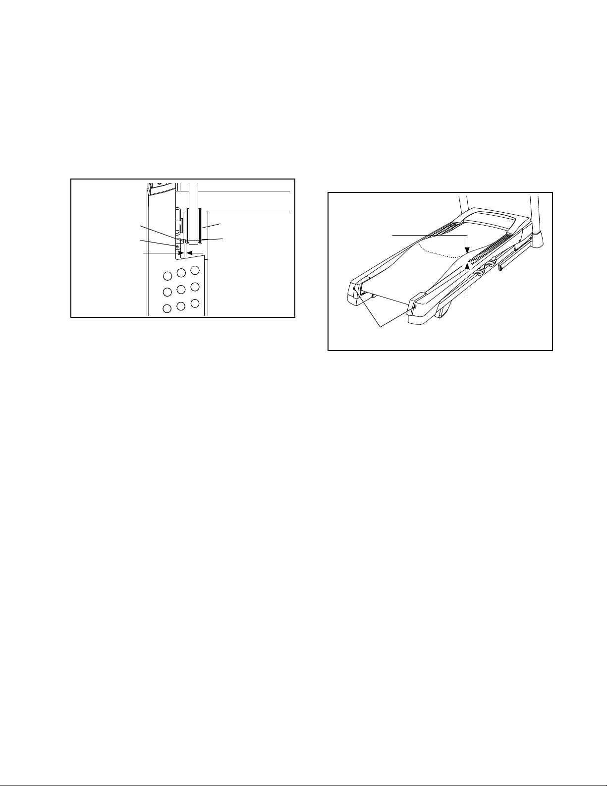
Locate the Reed Switch (52) and the Magnet (50)
on the left side of the Pulley (49). Turn the Pulley
until the Magnet is aligned with the Reed Switch.
Make sure that the gap between the Magnet and
the Reed Switch is about 1/8 in. (3 mm). If nec-
essary, loosen the #8 x 3/4" Tek Screw (14), move
the Reed Switch slightly, and then retighten the Tek
Screw. Reattach the Motor Hood (not shown) with
the #8 x 3/4" Tek Screws (not shown) and run the
treadmill for a few minutes to check for a correct
speed reading.
b. If the walking belt is overtightened, treadmill per-
formance may decrease and the walking belt may
become damaged. Remove the key and UNPLUG
THE POWER CORD. Using the hex key, turn both
idler roller screws counterclockwise, 1/4 of a turn.
When the walking belt is properly tightened, you
should be able to lift each edge of the walking belt
2 to 3 in. (5 to 7 cm) off the walking platform. Be
careful to keep the walking belt centered. Then,
plug in the power cord, insert the key, and run the
treadmill for a few minutes. Repeat until the walking belt is properly tightened.
Top
View
52
14
1/8 in.
SYMPTOM: The incline of the treadmill does not
change correctly
a. Hold down the Stop button and the Speed increase
button, insert the key into the console, and then
release the Stop button and the Speed increase
button. Next, press the Stop button and then
press the Incline increase or decrease button. The
treadmill will automatically rise to the maximum
incline level and then return to the minimum level.
This will recalibrate the incline system. If the incline
system does not begin calibrating, press the Stop
button again, and then press the Incline increase or
decrease button again. When the incline system is
calibrated, remove the key from the console.
49
50
b
2–3 in.
Idler Roller Screws
c. Your treadmill features a walking belt coated with
high-performance lubricant. IMPORTANT: Never
apply silicone spray or other substances to
the walking belt or the walking platform unless
instructed to do so by an authorized service
representative. Such substances may deteriorate the walking belt and cause excessive wear.
If you suspect that the walking belt needs more
lubricant, see the front cover of this manual.
d. If the walking belt still slows when walked on, see
the front cover of this manual.
SYMPTOM: The walking belt slows when walked on
a. Use only a surge suppressor that meets all of the
specications described on page 19.
31
Page 32
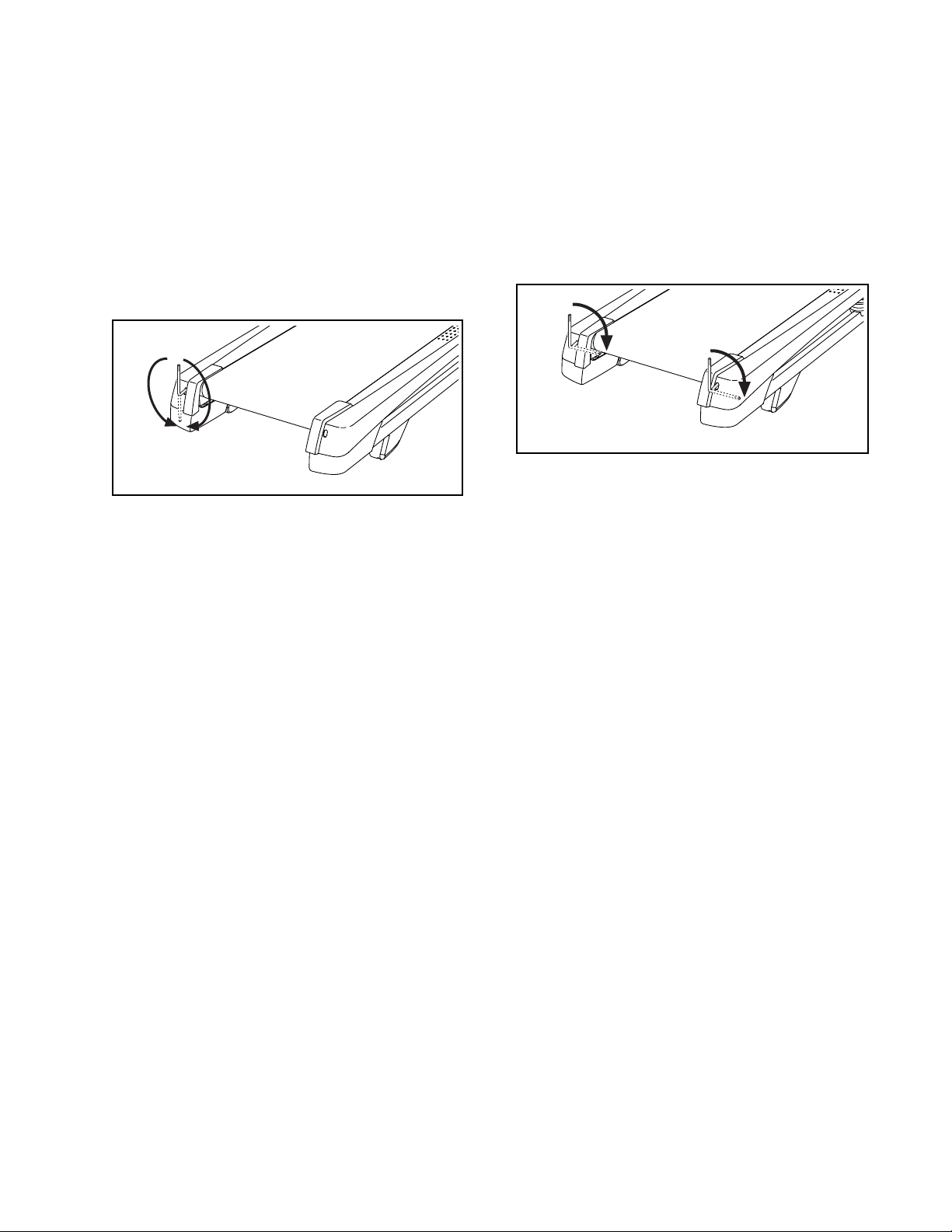
SYMPTOM: The walking belt is off-center or slips
when walked on
a. If the walking belt is off-center, rst remove the
key and UNPLUG THE POWER CORD. If the
walking belt has shifted to the left, use the hex
key to turn the left idler roller screw clockwise 1/2
of a turn; if the walking belt has shifted to the
right, turn the left idler roller screw counterclockwise 1/2 of a turn. Be careful not to overtighten the
walking belt. Then, plug in the power cord, insert
the key, and run the treadmill for a few minutes.
Repeat until the walking belt is centered.
a
b. If the walking belt slips when walked on, rst
remove the key and UNPLUG THE POWER
CORD. Using the hex key, turn both idler roller
screws clockwise, 1/4 of a turn. When the walking belt is correctly tightened, you should be able
to lift each edge of the walking belt 2 to 3 in. (5 to
7 cm) off the walking platform. Be careful to keep
the walking belt centered. Then, plug in the power
cord, insert the key, and carefully walk on the
treadmill for a few minutes. Repeat until the walking belt is properly tightened.
b
32
Page 33
EXERCISE GUIDELINES
WARNING: Before beginning this
or any exercise program, consult your physician. This is especially important for persons
over age 35 or persons with pre-existing
health problems.
The heart rate monitor is not a medical device.
Various factors may affect the accuracy of
heart rate readings. The heart rate monitor is
intended only as an exercise aid in determining heart rate trends in general.
These guidelines will help you to plan your exercise
program. For detailed exercise information, obtain a
reputable book or consult your physician. Remember,
proper nutrition and adequate rest are essential for
successful results.
EXERCISE INTENSITY
Whether your goal is to burn fat or to strengthen your
cardiovascular system, exercising at the proper intensity is the key to achieving results. You can use your
heart rate as a guide to find the proper intensity level.
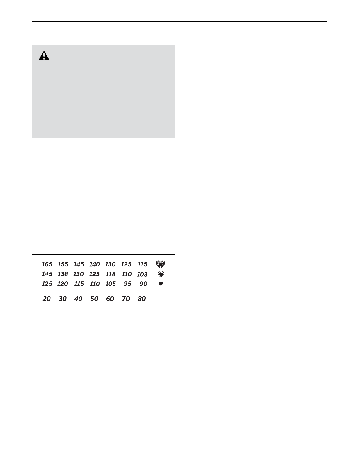
The chart below shows recommended heart rates for
fat burning and aerobic exercise.
Burning Fat—To burn fat effectively, you must exercise at a low intensity level for a sustained period of
time. During the first few minutes of exercise, your
body uses carbohydrate calories for energy. Only after
the first few minutes of exercise does your body begin
to use stored fat calories for energy. If your goal is to
burn fat, adjust the intensity of your exercise until your
heart rate is near the lowest number in your training
zone. For maximum fat burning, exercise with your
heart rate near the middle number in your training
zone.
Aerobic Exercise—If your goal is to strengthen your
cardiovascular system, you must perform aerobic
exercise, which is activity that requires large amounts
of oxygen for prolonged periods of time. For aerobic
exercise, adjust the intensity of your exercise until your
heart rate is near the highest number in your training
zone.
WORKOUT GUIDELINES
Warming Up—Start with 5 to 10 minutes of stretch-
ing and light exercise. A warm-up increases your body
temperature, heart rate, and circulation in preparation
for exercise.
Training Zone Exercise—Exercise for 20 to 30 minutes with your heart rate in your training zone. (During
the first few weeks of your exercise program, do not
keep your heart rate in your training zone for longer
than 20 minutes.) Breathe regularly and deeply as you
exercise; never hold your breath.
To find the proper intensity level, find your age at the
bottom of the chart (ages are rounded off to the nearest ten years). The three numbers listed above your
age define your “training zone.” The lowest number is
the heart rate for fat burning, the middle number is the
heart rate for maximum fat burning, and the highest
number is the heart rate for aerobic exercise.
Cooling Down—Finish with 5 to 10 minutes of stretching. Stretching increases the flexibility of your muscles
and helps to prevent post-exercise problems.
EXERCISE FREQUENCY
To maintain or improve your condition, complete three
workouts each week, with at least one day of rest
between workouts. After a few months of regular exercise, you may complete up to five workouts each week,
if desired. Remember, the key to success is to make
exercise a regular and enjoyable part of your everyday
life.
33
Page 34

PART LIST
Key No. Qty. Description Key No. Qty. Description
Model No. PFTL99513.3 R0115A
1 42 #8 x 1/2" Screw
2 39 #8 x 3/4" Screw
3 1 5/16" x 2 1/4" Bolt
4 4 5/16" x 1/2" Screw
5 4 #10 Star Washer
6 1 5/16" x 1 3/4" Bolt
7 6 3/8" x 4" Screw
8 2 5/16" x 1 1/2" Screw
9 4 #10 x 3/4" Screw
10 5 #8 x 1/2" Silver Screw
11 12 5/16" Star Washer
12 2 5/16" Nut
13 6 3/8" Star Washer
14 13 #8 x 3/4" Tek Screw
15 3 1/4" x 2 1/2" Screw
16 1 3/8" x 1 1/2" Bolt
17 2 3/8" x 1 1/2" Wheel Bolt
18 1 Console Frame
19 4 #8 x 7/16" Screw
20 2 5/16" Motor Screw
21 2 3/8" Pin
22 2 3/8" x 1" Bolt
23 4 5/16" x 1 3/4" Shoulder Bolt
24 12 #8 x 3/4" Pan Head Tek Screw
25 2 5/16" x 3/4" Screw
26 2 Rear Cushion Top
27 1 Right Tray
28 4 5/16" x 2 1/2" Screw
29 1 3/8" x 1 3/4" Hex Head Bolt
30 4 5/16" Flat Washer
31 1 Fan Grill
32 2 Incline Motor Spacer
33 6 3/8" Jam Nut
34 4 5/16" Nut
35 4 Cushion Bottom
36 1 Left Tray
37 1 Fan Cover
38 1 Latch Crossbar
39 4 Cushion
40 2 Hood Post
41 2 Console Clamp
42 1 Left Foot Rail
43 1 Caution Decal
44 1 Walking Platform
45 1 Walking Belt
46 2 Belt Guide
47 1 Right Rear Foot
48 4 Cable Tie
49 1 Drive Roller/Pulley
50 1 Magnet
51 1 Reed Switch Clip
52 1 Reed Switch
53 1 Storage Latch
54 1 Drive Motor
55 1 Motor Belt
56 1 Frame
57 1 Left Rear Foot
58 2 Console Ground Wire
59 4 Rubber Cushion
60 1 Right Foot Rail
61 1 Idler Roller
62 2 Front Wheel
63 2 Wheel Spacer
64 1 Console Base
65 1 Motor Hood
66 1 Hood Accent
67 2 Incline Frame Spacer
68 7 Hood Clip
69 1 Incline Motor
70 1 Incline Frame
71 2 Frame Spacer
72 1 Controller
73 1 Electronics Bracket
74 2 Base Cap
75 1 Power Switch
76 1 Power Cord
77 2 Grommet
78 1 Belly Pan
79 1 Left Handrail Cover
80 1 Console
81 1 Upright Wire
82 1 Left Base Cover
83 1 Right Base Cover
84 1 Right Bottom Handrail Cover
85 1 Left Bottom Handrail Cover
86 1 Left Handrail
87 1 Right Handrail
88 1 Console Trim
89 1 Left Upright
90 1 Right Upright
91 2 Warning Decal
92 1 Right Handrail Cover
93 1 Pulse Bar Bottom
94 1 Base
95 1 Pulse Bar
96 4 #4 Fan Screw
97 2 Wheel
98 1 Key/Clip
99 3 Cable Tie
100 2 1/4" x 1 1/2" Screw
34
Page 35

Key No. Qty. Description Key No. Qty. Description
101 1 Fan
102 5 #8 x 3/4" Truss Head Screw
103 1 Left Rear Cap
104 1 Right Rear Cap
105 1 1/4" Nut
106 1 Console Clamp
107 2 #8 x 1 3/4" Screw
108 6 #8 x 3/4" Washer Head Screw
109 2 Base Pad
Note: Specications are subject to change without notice. For information about ordering replacement parts, see
the back cover of this manual. *These parts are not illustrated.
110 1 Left Foot Pad
111 1 Right Foot Pad
112 1 Left Front Cushion Top
113 1 Right Front Cushion Top
114 4 1/4" x 2 1/4" Screw
115 4 #8 x 1/2" Machine Screw
116 1 Tablet Holder
* – User’s Manual
35
Page 36
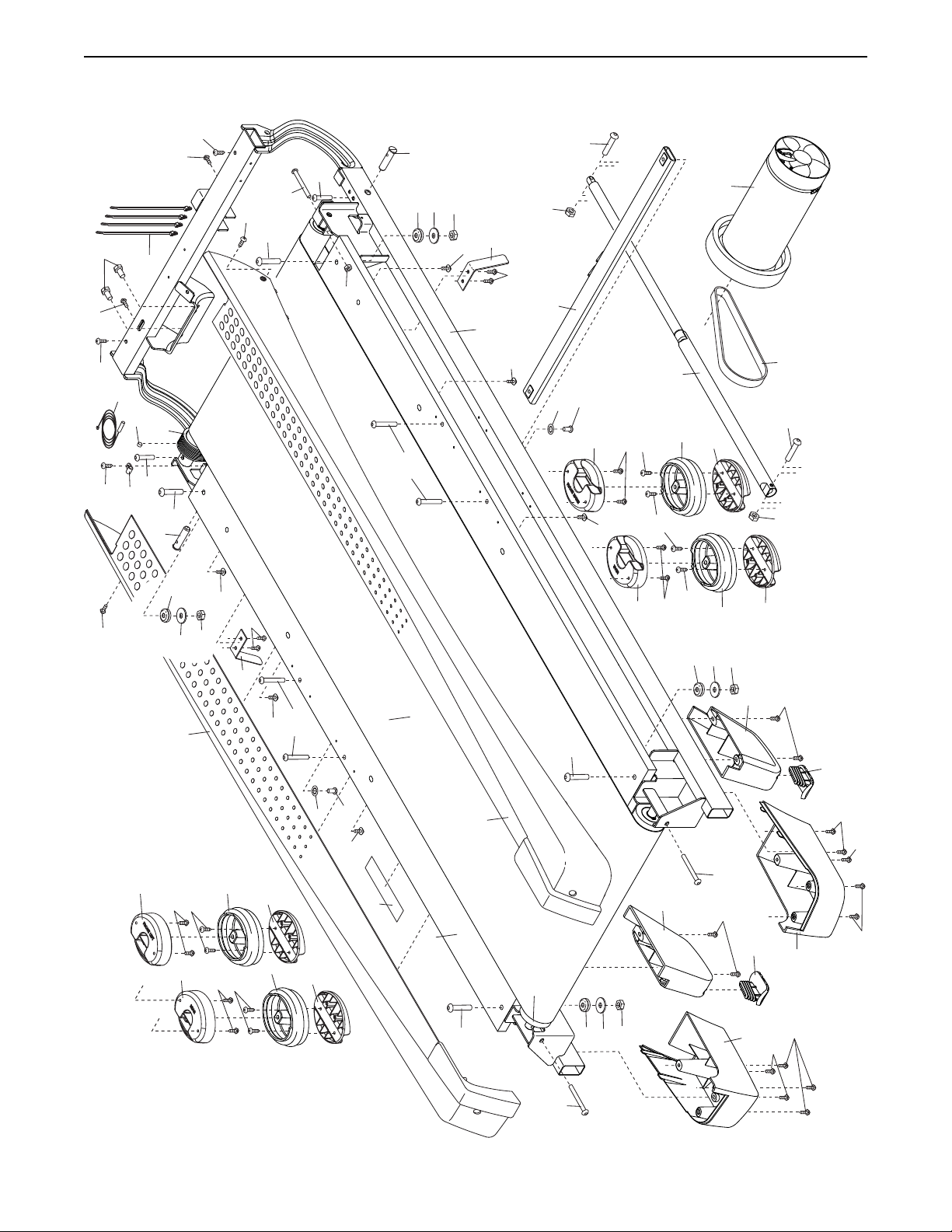
EXPLODED DRAWING A
Model No. PFTL99513.3 R0115A
10
20
107
14
102
52
51
50
48
100
21
49
23
59
10
30
42
107
34
108
102
19
46
23
108
15
12
38
11
23
6
25
113
108
54
47
55
3
12
35
24
111
53
39
14
59
35
30
39
34
2
14
14
2
26
21
100
30
59
34
46
108
19
105
56
108
114
114
45
25
11
108
112
2
26
14
39
35
39
2
14
35
43
44
23
60
61
59
30
34
57
15
24
110
103
2
24
24
2 2
104
15
36
Page 37
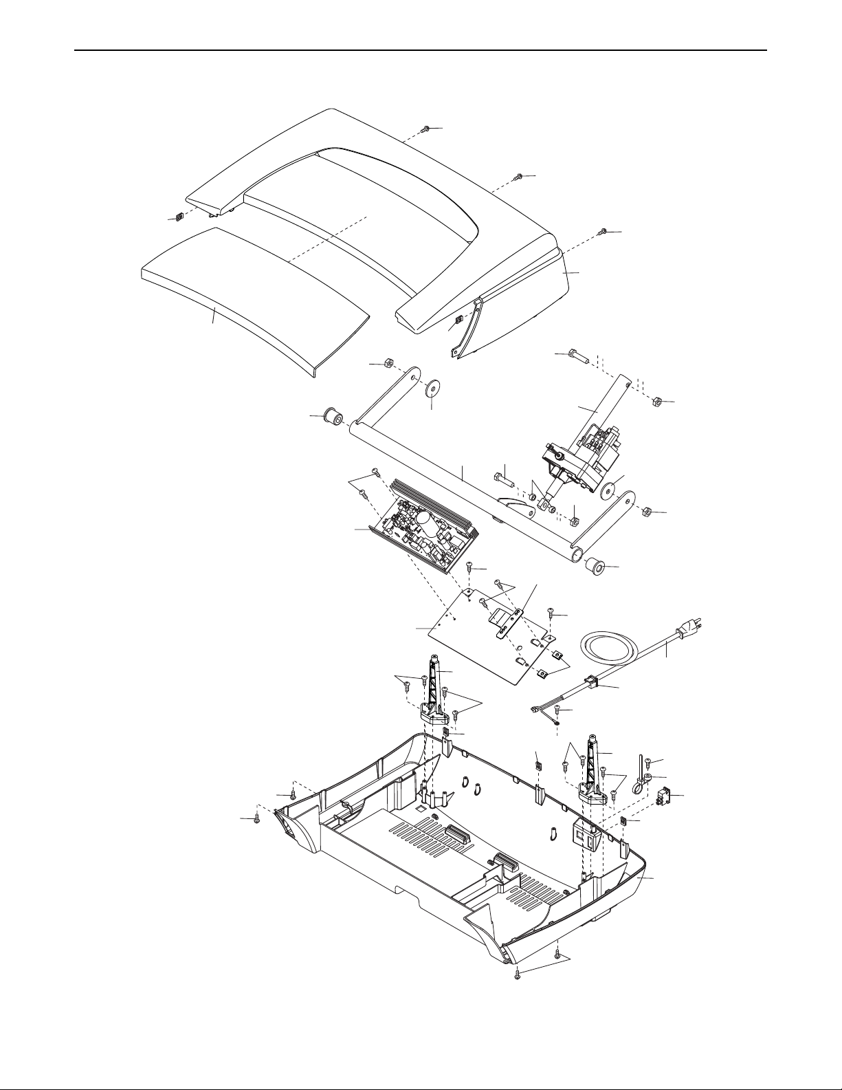
EXPLODED DRAWING B
Model No. PFTL99513.3 R0115A
102
102
68
66
71
2
72
33
73
67
68
70
102
65
29
69
16
32
33
2
106
2
2
67
71
33
33
24
24
2
40
68
2
68
68
10
2
40
24
77
76
2
2
99
75
68
78
37
Page 38
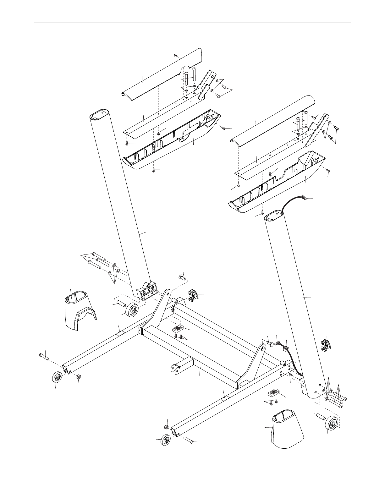
EXPLODED DRAWING C
79
Model No. PFTL99513.3 R0115A
1
28
11
11
4
17
82
86
1
1
1
89
7
13
63
62
91
85
1
22
74
109
14
92
1
87
1
22
81
28
11
1
77
84
90
81
1
11
74
4
1
97
33
97
33
38
94
17
91
14
83
10
109
13
7
63
62
Page 39
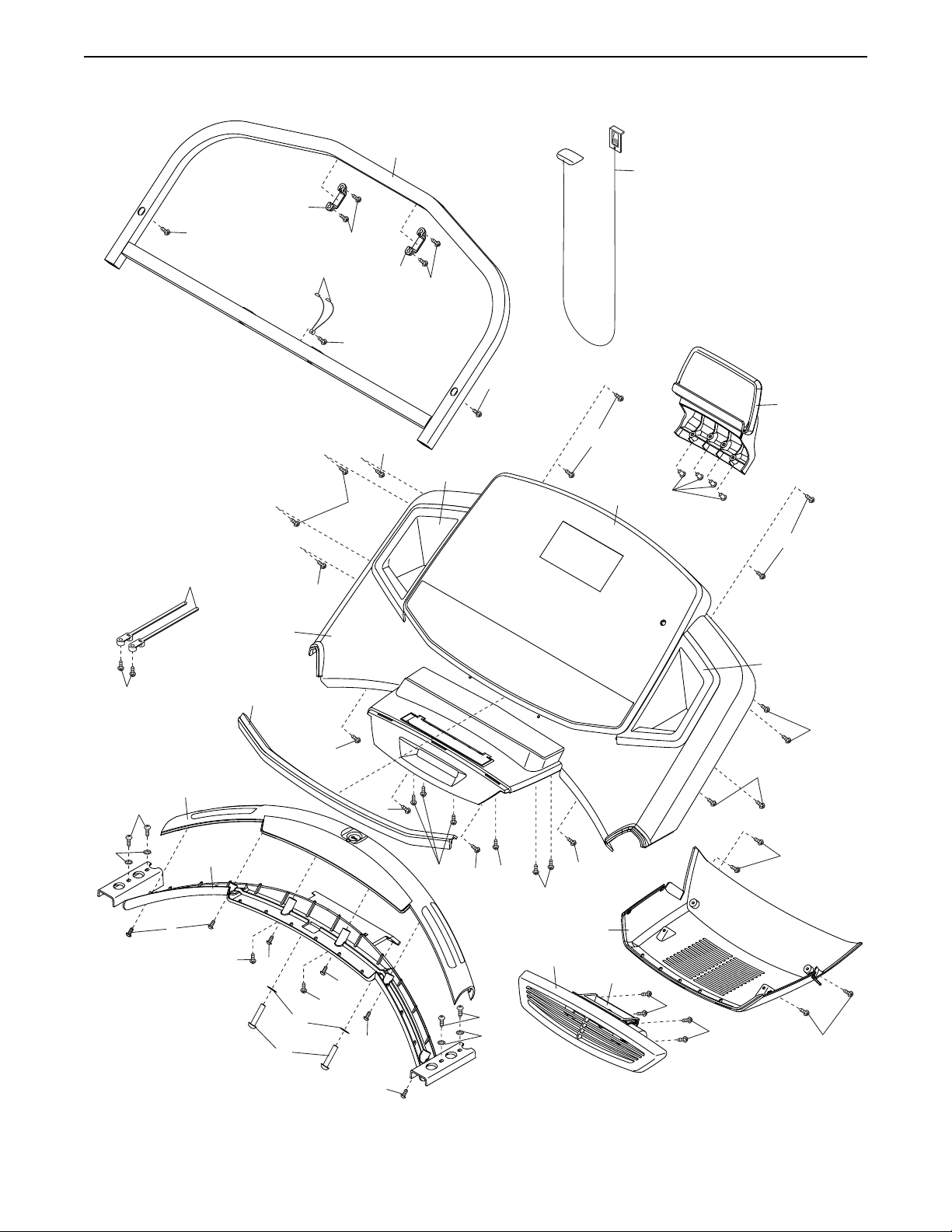
EXPLODED DRAWING D
18
41
1
2
Model No. PFTL99513.3 R0115A
98
58
99
2
88
1
64
10
41
2
1
116
1
36
1
1
115
80
1
27
1
1
1
95
9
5
93
1
2
1
2
11
8
2
1
1
1
1
1
2
9
5
1
1
37
31
101
96
96
1
1
39
Page 40
ORDERING REPLACEMENT PARTS
To order replacement parts, please see the front cover of this manual. To help us assist you, be prepared to
provide the following information when contacting us:
• the model number and serial number of the product (see the front cover of this manual)
• the name of the product (see the front cover of this manual)
• the key number and description of the replacement part(s) (see the PART LIST and the EXPLODED DRAWING
near the end of this manual)
LIMITED WARRANTY
IMPORTANT: To protect your fitness equipment with an extended service plan, see page 6.
ICON Health & Fitness, Inc. (ICON) warrants this product to be free from defects in workmanship and
material, under normal use and service conditions. The frame and motor are warranted for a lifetime. Parts
are warranted for three (3) years from the date of purchase. Labor is warranted for one (1) year from the
date of purchase.
This warranty extends only to the original purchaser (customer). ICON’s obligation under this warranty is
limited to repairing or replacing, at ICON’s option, the product through one of its authorized service centers.
All repairs for which warranty claims are made must be preauthorized by ICON. If the product is shipped
to a service center, freight charges to and from the service center will be the customer’s responsibility. If
replacement parts are shipped while the product is under warranty, the customer will be responsible for a
minimal handling charge. For in-home service, the customer will be responsible for a minimal trip charge.
This warranty does not extend to freight damage to the product. This warranty will automatically be voided
if the product is used as a store display model, if the product is purchased or transported outside the USA,
if all instructions in this manual are not followed, if the product is abused or improperly or abnormally used,
or if the product is used for commercial or rental purposes. No other warranty beyond that specically set
forth above is authorized by ICON.
ICON is not responsible or liable for indirect, special, or consequential damages arising out of or in connection with the use or performance of the product; damages with respect to any economic loss, loss of
property, loss of revenues or prots, loss of enjoyment or use, or costs of removal or installation; or other
consequential damages of any kind. Some states do not allow the exclusion or limitation of incidental or
consequential damages. Accordingly, the above limitation may not apply to the customer.
The warranty extended hereunder is in lieu of any and all other warranties, and any implied warranties of
merchantability or tness for a particular purpose are limited in their scope and duration to the terms set
forth herein. Some states do not allow limitations on how long an implied warranty lasts. Accordingly, the
above limitation may not apply to the customer.
This warranty provides specic legal rights; the customer may have other rights that vary from state to state.
ICON Health & Fitness, Inc., 1500 S. 1000 W., Logan, UT 84321-9813
Part No. 366001 R0115A Printed in USA © 2015 ICON Health & Fitness, Inc.
 Loading...