

Page 1
Model No. PFEX74051
Serial No. ____________________
Serial
Number
Decal
P
atent Pending
QUESTIONS?
As a manufacturer, we are
committed to providing complete
customer satisfaction. If you
have questions, or find that there
are missing or damaged parts,
we will guarantee you complete
satisfaction through direct
assistance from our factory.
TO AVOID UNNECESSARY
DELAYS, PLEASE CALL DIRECT
TO OUR TOLL-FREE CUSTOMER
HOT LINE. The trained technicians on our Customer Hot
Line will provide immediate
assistance, free of charge to you.
CUSTOMER HOT LINE:
1-800-999-3756
Mon.-Fri., 6 a.m.-6 p.m. MST
CAUTION:
Read all precautions and instructions in this manual before using
this equipment. Save this manual
for future reference.
USER'S MANUAL
Page 2

TABLE OF CONTENTS
IMPORTANT SAFETY PRECAUTIONS . . . . . . . . . . . . . . . . . . . . . . . . . . . . . . . . . . . . . . . . . . . . . . . . . . . . . . . . .
BEFORE YOU BEGIN . . . . . . . . . . . . . . . . . . . . . . . . . . . . . . . . . . . . . . . . . . . . . . . . . . . . . . . . . . . . . . . . . . . . . . .
PART CHART . . . . . . . . . . . . . . . . . . . . . . . . . . . . . . . . . . . . . . . . . . . . . . . . . . . . . . . . . . . . . . . . . . . . . . . . . . . . .
ASSEMBLY . . . . . . . . . . . . . . . . . . . . . . . . . . . . . . . . . . . . . . . . . . . . . . . . . . . . . . . . . . . . . . . . . . . . . . . . . . . . . . .
ADJUSTMENT AND OPERATION . . . . . . . . . . . . . . . . . . . . . . . . . . . . . . . . . . . . . . . . . . . . . . . . . . . . . . . . . . . . .
ROUBLE-SHOOTING AND MAINTENANCE . . . . . . . . . . . . . . . . . . . . . . . . . . . . . . . . . . . . . . . . . . . . . . . . . . .
T
CONDITIONING GUIDELINES . . . . . . . . . . . . . . . . . . . . . . . . . . . . . . . . . . . . . . . . . . . . . . . . . . . . . . . . . . . . . . .
PART LIST . . . . . . . . . . . . . . . . . . . . . . . . . . . . . . . . . . . . . . . . . . . . . . . . . . . . . . . . . . . . . . . . . . . . . . . . . . . . . . .
EXPLODED DRAWING . . . . . . . . . . . . . . . . . . . . . . . . . . . . . . . . . . . . . . . . . . . . . . . . . . . . . . . . . . . . . . . . . . . . .
ORDERING REPLACEMENT PARTS . . . . . . . . . . . . . . . . . . . . . . . . . . . . . . . . . . . . . . . . . . . . . . . . . .
LIMITED WARRANTY . . . . . . . . . . . . . . . . . . . . . . . . . . . . . . . . . . . . . . . . . . . . . . . . . . . . . . . . . . . . . .
Back Cover
Back Cover
1
12
14
15
2
3
4
5
8
1
IMPORTANT PRECAUTIONS
WARNING: To reduce the risk of serious injury, read the following important precautions before using the
exercise bike.
1. It is the responsibility of the owner to ensure
that all users of the exercise bike are
adequately informed of all precautions.
2. Place the exercise bike on a level surface.
3. Use the exercise bike only as described in this
manual.
4. Keep small children and pets away from the
exercise bike at all times.
5. Wear appropriate clothing when exercising;
do not wear loose clothing that could become
caught in the exercise bike. Always wear
athletic shoes for foot protection.
WARNING: Before beginning this or any exercise program, consult your physician. This is especially
important for persons over the age of 35 or persons with pre-existing health problems. Read all
instructions before using this product. ICON assumes no responsibility for personal injury or property
damage sustained by or through the use of this product.
2
6. When connecting the link arms to the pedals
(see HOW TO USE THE HANDLEBARS on page
8), make sure that the link arms are on the
pedal bushings. If the link arms are not on the
pedal bushings, they may slip off during use.
7. Always connect the link arms to the lock rod
when the link arms are not connected to the
pedals (see HOW TO USE THE HANDLEBARS
on page 8).
When adjusting the seat, at least two inches of
8.
the seat post must be inside of the frame. The
seat pin must be inserted from the front, as
shown on page 3. If the seat pin is inserted
from the back, it may slip out during use.
Page 3
BEFORE YOU BEGIN
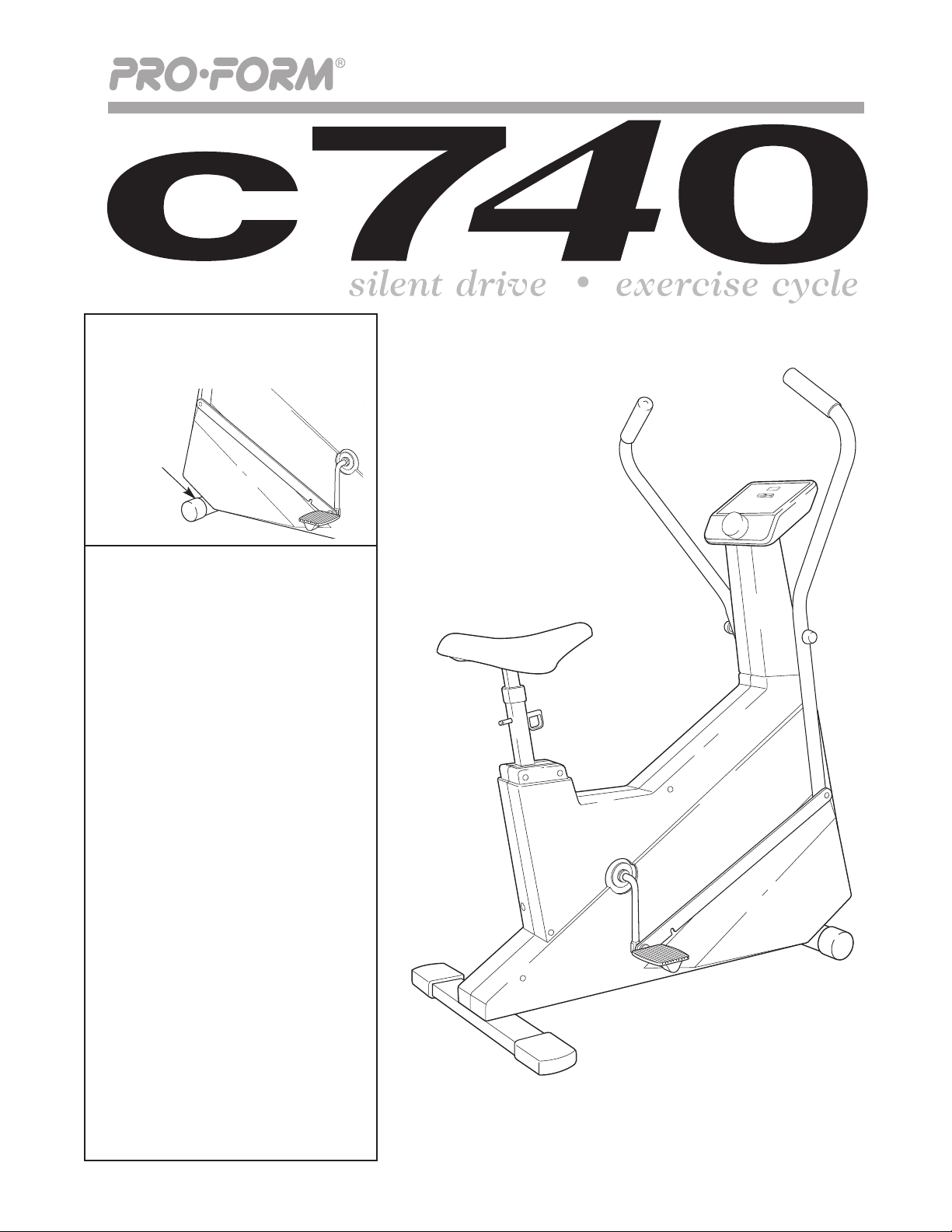
ongratulations for selecting the PROFORM
C
exercise bike. Cycling is one of the most effective
xercises known for increasing cardiovascular fitness,
e
building endurance and toning the entire body. The
sophisticated PROFORM C740 offers an impressive
array of features designed to let you enjoy this healthful
exercise in the convenience and privacy of your home.
For your benefit, read this manual carefully before
using the exercise bike.
questions, please call our Customer Service
Console
If you have additional
®
740
C
Handlebars
epartment toll-free at 1
D
through Friday, 6 a.m. until 6 p.m. Mountain Time
excluding holidays). To help us assist you, please
(
mention the product model number and serial number
when calling. The model number is PFEX74051. The
serial number can be found on a decal attached to the
exercise bike (see the front cover of this manual).
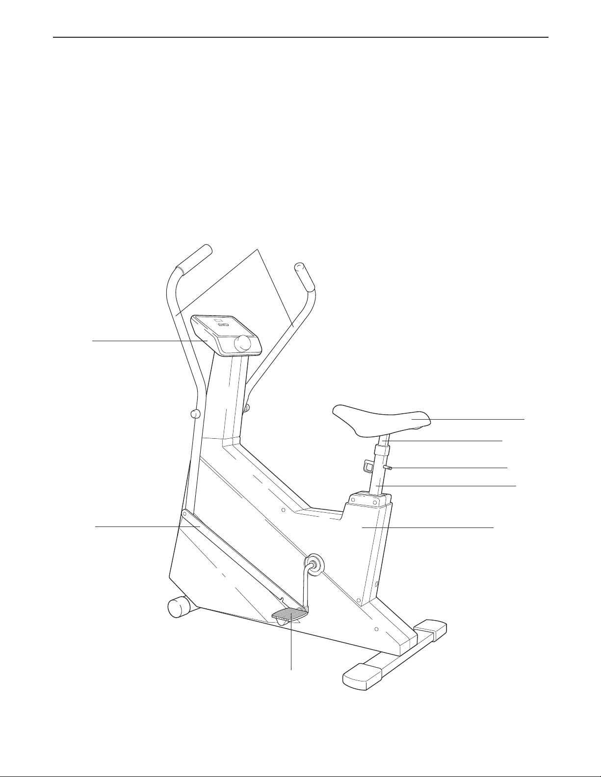
Before reading further, please review the drawing
below and familiarize yourself with the parts that are
labeled.
-800-999-3756,Monday
Link Arm
Seat
Seat Post
Seat Pin
Frame
Side Shield
FRONT
LEFT SIDE
BACK
Pedal
3
Page 4
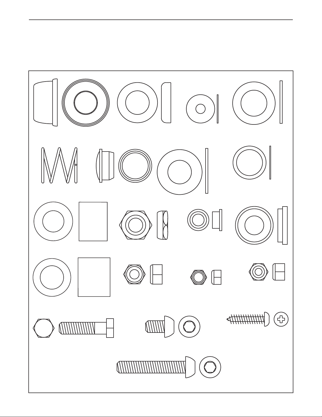
PART CHART
5/8" Plastic Cap (3)–2
Pedal Spring (52)–2
Pedal Bushing (55)–2
Link Arm Bushing (58)–2
5/16" Washer (65)–2
11/16" Spring Washer (51)–2
11/16" Washer (54)–2
5/8" Spacer (57)–2
Pedal Cap (50)–2
9/16" Washer (56)–2
9/16" Pedal Spacer (62)–2
1/2" Nylon Locknut (46)–2
1/4" Seat Nut (7)–4
1/4" x 1/2" Screw (33)–2
5/16" x 18 Nut (17)–2
Handlebar Spacer (53)–2
#8 x 1" Screw (15)–4
5/16" Nut (49)–4
5/16" x 1 1/4" Bolt (14)–2
5/16" x 1 3/4" Bolt (36)–2
Use the part chart below to identify the small parts used in assembly. The number in parenthesis beneath each
part refers to the key number of the part. The second number refers to the quantity used in assembly. Note:
Some of the parts used in assembly may have been pre-attached to one of the parts to be assembled. If a part is
missing, see the back cover of this manual for instruction.
4
Page 5
ASSEMBLY
Place all parts of the exercise bike in a cleared area
and remove the packing materials. Do not dispose
of the packing materials until assembly is completed.
Read all steps and examine all drawings carefully
before beginning.
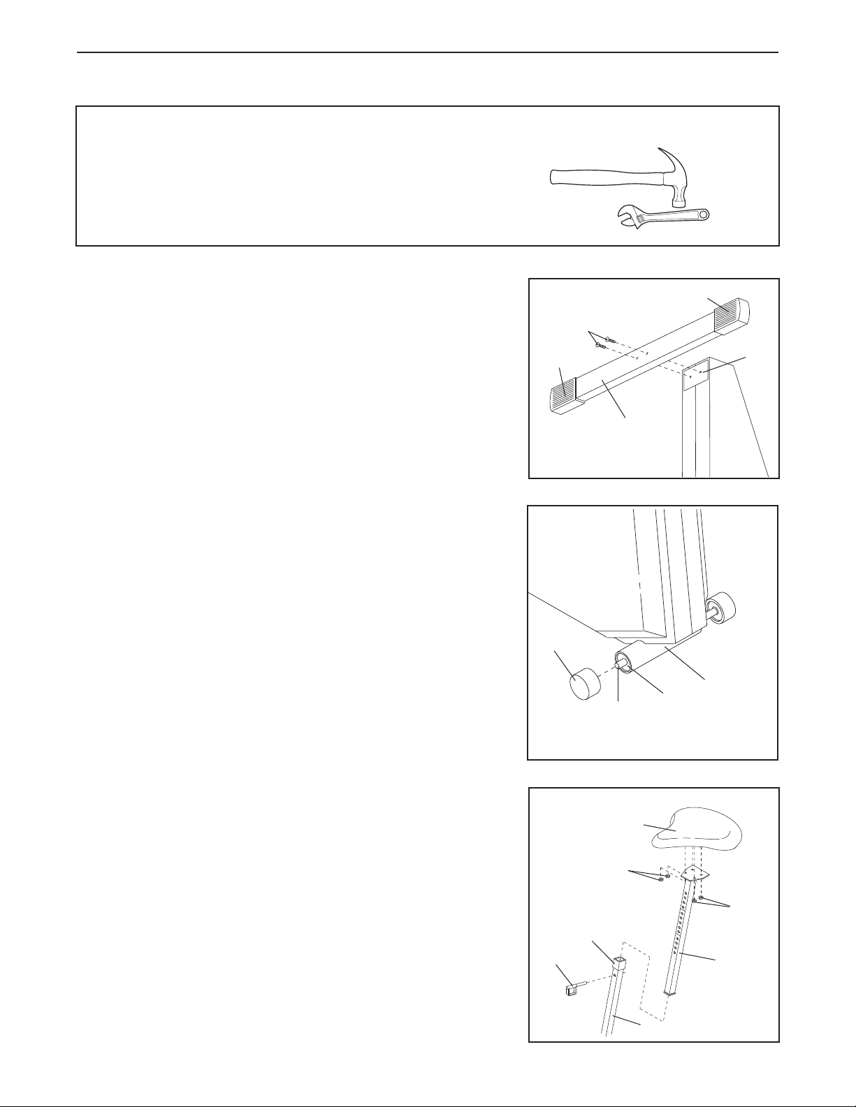
1. Raise the back end of the exercise bike. Attach the Stabilizer
(13) to the Frame (11) with the two 5/16" x 1 1/4" Bolts (14).
The Stabilizer must be turned so the ribbed sides of the
Endcaps (12) are on the side shown. Lower the exercise bike.
2. Slide the free end of the Roller Axle (42) through the Bushings
(43) in the Frame (11). Press the unattached Roller (24) onto
the end of the Axle. It may be helpful to tap the Roller with a
hammer in order to press it fully onto the Axle.
In addition to the included tools, the following
tools are required for assembly:
ne (1) hammer
o
one (1) adjustable wrench
1
14
12
13
2
12
11
3. Remove the four 1/4" Seat Nuts (7) from the underside of the
Seat (5). Remove the Seat Post (6) from the Frame (11). Attach
the Seat to the top of the Seat Post with the four 1/4" Seat Nuts.
Insert the Seat Post (6) into the Frame (11). Adjust the Seat (5)
to the desired height and insert the Seat Pin (8) through the front
of the Frame and the Seat Post. Slide the Seat Post Collar (30)
down over the Frame.
Seat Post must be inside of the Frame. The Seat Pin must
be inserted from the front, as shown. If the Seat Pin is
inserted from the back, it may slip out.
CAUTION: At least two inches of the
24
42
43
3
5
7
30
8
11
11
7
6
5
Page 6
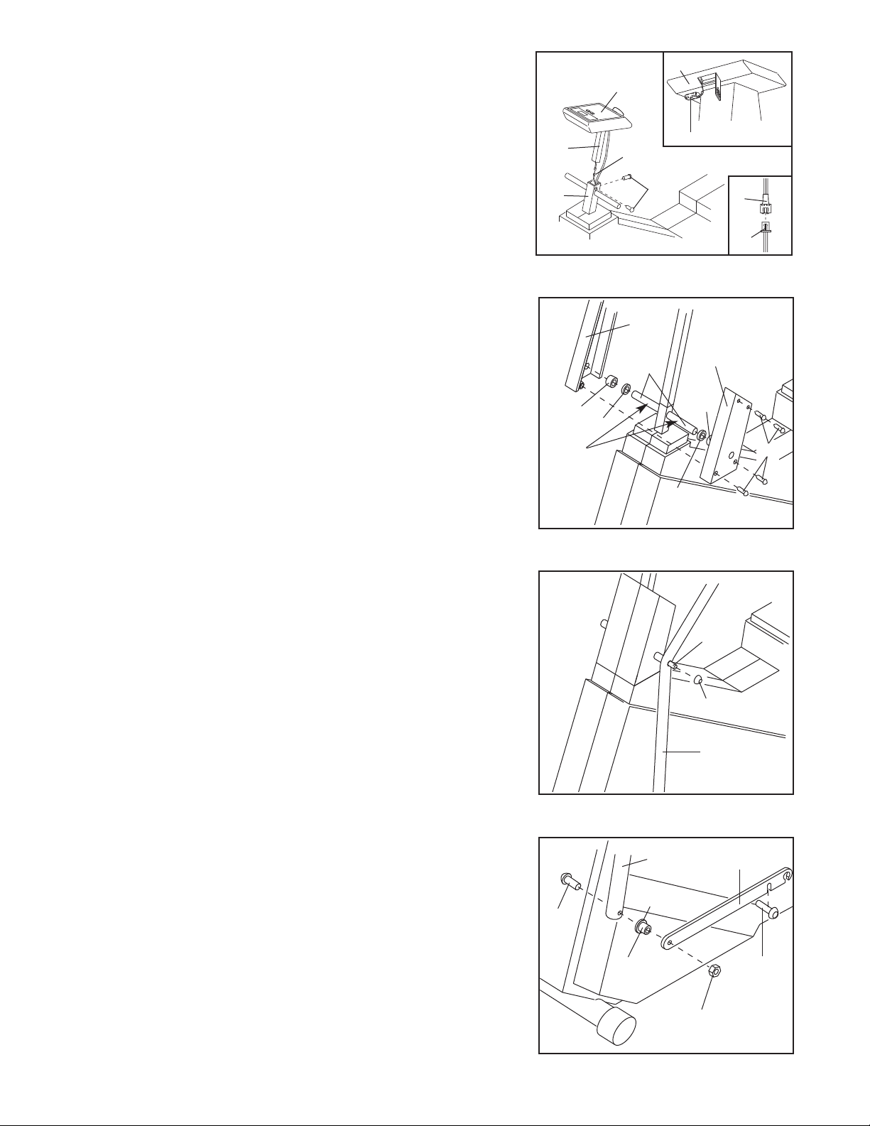
4. The Console (1) requires two “AA” batteries (not included);
lkaline batteries are recommended. Slide open the battery
a
cover on the front of the Console (see the upper inset drawing).
ind the markings inside the battery clip showing which
F
direction the batteries must be turned. Press two batteries into
the battery clip. Close the battery cover.
ttach the wire extending from the Console (1) to the Sensor
A
ire (44) (see the lower inset drawing). Slide the Console
W
Mount (2) onto the Frame (11).
your fingers or the Sensor Wire.
the Frame with the two 1/4” x 1/2” Screws (33).
Be careful to avoid pinching
Attach the Console Mount to
33
1
B
attery Clip
1
44
4
1
2
11
44
5. Apply grease (included) to the handlebar shaft of the Frame
(11). Slide a 5/8" Spacer (57) and a Handlebar Spacer (53) onto
each side of the handlebar shaft.
of each 5/8” Spacer is turned toward the Frame.
Slide the Left and Right Neck Shields (67, 68) onto the
handlebar shaft on the Frame (11). Insert the four #8 x 1”
Screws (15) into the Left Neck Shield, and tighten them into the
Right Neck Shield.
6. Slide a Handlebar (9) onto the left side of the handlebar shaft on
the Frame (11). Tap a 5/8" Plastic Cap (3) onto the handlebar
shaft.
Attach the other Handlebar to the other side of the handlebar
shaft in the same manner (not shown).
Make sure that the open side
5
53
Apply
Grease
6
57
68
11
67
53
15
57
11
3
7. Insert a 5/16" x 1 3/4" Bolt (36) through the lower end of the left
Handlebar (9).
may have a rough edge. Be careful to avoid cutting your
fingers. Tap a Link Arm Bushing (58) into a Link Arm (37). Slide
the Link Arm onto the Bolt. The flange of the Link Arm Bushing
must be turned toward the Handlebar, and the opening in the
end of the Link Arm must be downward as shown. Tighten a
5/16" x 18 Nut (17) onto the Bolt.
the Link Arm must pivot freely. Clip the Link Arm onto the lock
rod.
Attach the other Link Arm to the right Handlebar (not shown) in
6
the same manner.
CAUTION: The lower end of the Handlebar
Do not overtighten the Nut;
7
36
58
9
Flange
9
37
Lock
Rod
17
Page 7

8. Hold one of the Pedal Shafts (38) with the included tool as shown—the tool must be between the coils of the
Pedal Spring (52). Using an adjustable wrench, remove the 1/2" Nylon Locknut (46) from the end of the Pedal
haft. Make sure that there is an 11/16" Spring Washer (51), a Pedal Spring (52), an 11/16" Washer (54), a
S
Pedal Bushing (55), a 9/16" Washer (56), and a 9/16” Pedal Spacer (62) on the Pedal Shaft.
Using the included tool, firmly tighten the Pedal Shaft (38), in a clockwise direction, into one arm of the Crank
(27). While holding the Pedal Shaft with the tool, use an adjustable wrench to tighten the 1/2" Nylon Locknut
(46) back onto the end of the Pedal Shaft. There is a 5/16" Washer (65) and a 5/16" Nut (49) on the other end
of the Pedal Shaft.
Pedal Cap (50) into the Pedal (10).
Attach the other Pedal Shaft to the other arm of the Crank (not shown) in the same manner.
8
Make sure that the 5/16" Nut (49) is flush with the end of the Pedal Shaft. Press a
50
49
65
10
51 38
52
Tool
54 55 56
62
27
46
7
Page 8

ADJUSTMENT AND OPERATION
SEAT ADJUSTMENT
For effective exercise, the Seat (5) should be adjusted to the proper
height. As you pedal, there should be a slight bend in your knees
when the pedals are at the lowest position. Dismount the exercise
bike. Hold the Seat and remove the Seat Pin (8). Adjust the Seat to
the proper height and insert the Seat Pin through the Frame (11)
and the Seat Post (6). CAUTION: At least two inches of the Seat
Post must be inside of the Frame. The Seat Pin must be
inserted from the front, as shown. If the Seat Pin is inserted
from the back, it may slip out during use.
HOW TO USE THE HANDLEBARS
The handlebars can be used in any of three modes: the dual-action mode, for lower- and upper-body exercise; the
stationary mode, for lower-body exercise; or the rowing mode, for upper-body exercise.
DUAL-ACTION MODE
5
6
8
11
To use the handlebars in the dual-action mode, connect the link
arms to the pedals in the following manner:
1. Lift each Link Arm (37) off the lock rod.
2. Pull each Link Arm (37) outward against the top of the 11/16"
Washer (54), while pulling against the bottom of the 11/16"
Washer with your fingers.
pinching your fingers. Slide each Link Arm onto the Pedal
Bushing (55). It may be helpful to move the Link Arms up and
down slightly until they slide onto the Pedal Bushings. CAUTION:
Make sure that the Link Arms are on the Pedal Bushings. If
the Link Arms are not on the Pedal Bushings, they may slip
off during use.
STATIONARY MODE
CAUTION: Be careful to avoid
1
37
Lock Rod
2
54
55
37
To use the handlebars in the stationary mode, the link arms must be disconnected from the pedals. See drawing
2 above. Pull each Link Arm (37) outward against the 11/16" Washer (54), until the Link Arm can be lifted off the
Pedal Bushing (55). CAUTION: Be careful to avoid pinching your fingers. See drawing 1 above. Clip each
Link Arm (37) onto the lock rod.
ROWING MODE
To use the handlebars in the rowing mode, the link arms must be connected to the pedals. See DUAL-ACTION
MODE above. Rest your feet on the side shields, and exercise using only your arms.
8
Page 9

RESISTANCE ADJUSTMENT
To vary the intensity of your exercise, the pedaling resistance can be
adjusted. The resistance is controlled by turning the Resistance Knob
(48) on the Console (1). To increase the resistance, turn the
Resistance Knob clockwise; to decrease the resistance, turn the
esistance Knob counterclockwise. IMPORTANT: Stop turning the
R
Resistance Knob when turning becomes difficult, or the exercise
ike may be damaged.
b
ELECTRONIC MONITOR MODES
SPEED—Displays your pedaling speed, in miles per hour.
TIME—Displays the elapsed time. Note: Time will be counted only while you are pedaling. If you stop for ten
seconds or longer, the time will hold until you resume pedaling.
DISTANCE—Displays the total distance you have pedaled, in miles.
CALORIE—Displays the total number of Calories you have burned. Note: If the pedaling resistance is near the
lowest or highest setting, the actual number of Calories you have burned will be slightly lower or higher than the
number displayed.
Resistance Knob
SCAN—Displays the SPEED, TIME, DISTANCE and CALORIE modes in a repeating cycle.
ELECTRONIC MONITOR DIAGRAM
1. LCD display—Display for all modes.
2. Mode indicator—Shows which mode is currently
selected.
3. Mode button—Selects modes.
4. On/off button—Turns the power on and off and
resets the display.
ELECTRONIC MONITOR OPERATION
Note: The electronic monitor requires two "AA" size batteries (not included). See assembly step 4 on page 6 for
battery installation instructions.
1. To turn on the power, press the on/off button or simply begin pedaling.
2. Select one of the five modes:
1
2
3
4
A. SCAN—When the power is turned on, the SCAN mode will be selected automatically. A mode indicator will
appear by the word "SCAN." The SPEED, TIME, DISTANCE and CALORIE modes will all be displayed, for
five seconds each, in a repeating cycle. A second mode indicator will show which mode is currently
displayed.
B. SPEED, TIME, DISTANCE or CALORIE—The SPEED, TIME, DISTANCE or CALORIE mode can be
continuously displayed. To select one of these modes, press the mode button repeatedly. A mode indicator
will appear to show which mode you have selected. (Make sure that the SCAN mode is not selected.) The
modes will be selected in the following order: SPEED, TIME, DISTANCE, CALORIE, SCAN.
9
Page 10

3. To reset the LCD display, turn the power off and then on again by pressing the on/off button twice.
. When you are finished exercising, press the on/off button to turn off the power. N
4
turned and the electronic monitor buttons are not pressed for four minutes, the power will turn off
utomatically in order to conserve the batteries.
a
ELECTRONIC MONITOR CARE
Keep the electronic monitor out of direct sunlight, or the LCD display may be damaged. Clean the monitor
periodically using a soft, dry cloth. Do not allow liquids to come in contact with the monitor.
ote: If the pedals are not
10
Page 11

TROUBLE-SHOOTING AND MAINTENANCE
Inspect and tighten all parts regularly. Outer surfaces of the exercise bike can be cleaned with a damp cloth and
mild, non-abrasive detergent. Keep liquids away from the console.
ONSOLE
C
If the console does not function properly, the batteries should be replaced. See assembly step 4 on page 6. Make
sure that the sensor wire is plugged fully into the wire extending from the console.
ADJUSTING THE TENSION BELT
If the tension belt slips as you pedal, the tension belt should
be tightened. First, disconnect the Link Arms (37) from the
Pedals (10) (see STATIONARY MODE on page 8). Next,
remove the Pedals (see assembly step 8 on page 7). Remove
the four #8 x 1” Screws (15) from the Left and Right Neck
Shields (67, 68). Remove the #8 x 1" Screws (15) and the 3/4"
Tec Screws (69) from the Left and Right Side Shields (16, 34).
Slide the Side Shields off the exercise bike. To tighten the
tension belt, turn both of the 1/4" Nylon Locknuts (18)
clockwise one full turn. Repeat until the tension belt no longer
slips. Reattach the Side Shields, Neck Shields and Pedals.
15
15
67
37
69
69
68
9
10
15
16
CENTERING THE TENSION BRACKET
If a grinding noise is heard as you pedal, the Tension Bracket
(35) should be adjusted. Disconnect the link arms from the
pedals, remove the pedals, and remove the side shields (see
ADJUST
Locknut (31) with a wrench. If the Tension Bracket is touching
the right side of the Resistance Disk (22), turn the Tension
Bracket Bolt (60) clockwise until the Tension Bracket is
centered. If the Tension Bracket is touching the left
Resistance Disk, turn the Bolt counterclockwise. Reattach the
side shields, neck shields and pedals.
TIGHTENING THE CRANK ARMS
If the crank arms become loose, they should be tightened in
order to prevent excessive wear. Loosen the hex nut on the
left arm of the Crank (27). Place the end of a standard
screwdriver in one of the grooves in the crank nut. Lightly tap
the screwdriver with a hammer to turn the
counterclockwise, until the crank arms are no longer loose.
Do not overtighten the crank nut. When the crank nut is
properly tightened, tighten the hex nut.
ING THE TENSION BELT above). Hold the 3/8" x 16
side of the
crank nut
18
Top View
35
60
Left Side Shield
Crank
Nut
Hex Nut
22
31
15
35
27
1
1
Page 12

CONDITIONING GUIDELINES
The following guidelines will help you to plan your
exercise program. Remember that proper nutrition and
adequate rest are essential for successful results.
WARNING: Before beginning this or any exercise
program, consult your physician. This is especially
important for persons over the age of 35 or
persons with pre-existing health problems.
EXERCISE INTENSITY
To maximize the benefits of exercising, it is important
to exercise with the proper intensity. The proper
intensity level can be found by using your heart rate as
a guide. For effective aerobic exercise, your heart rate
should be maintained at a level between 70% and 85%
of your maximum heart rate as you exercise. This is
known as your training zone.
You can find your training zone in the table below.
Training zones are listed for both unconditioned and
conditioned persons according to age.
UNCONDITIONED
TRAINING ZONE
AGE
20 138-167 133-162
25 136-166 132-160
30 135-164 130-158
35 134-162 129-156
40 132-161 127-155
45
50 129-156 124-150
55 127-155 122-149
60 126-153 121-147
65 125-151 119-145
70 123-150 118-144
75 122-147 117-142
80 120-146 115-140
85 118-144 114-139
(BEATS/MIN
131-159
CONDITIONED
TRAINING ZONE
(BEATS/MIN
125-153
During the first few months of your exercise program,
keep your heart rate near the low end of your training
zone as you exercise. After a few months, your heart
rate can be increased gradually until it is near the middle of your training zone as you exercise.
To measure
your heart
rate, stop
exercising and
place two
fingers on your
wrist. Take a
six-second
heartbeat
count, and
multiply the
result by 10 to
find your heart rate. For example, if your six-second
heartbeat count is 14, your heart rate is 140 beats per
minute. (A six-second count is used because your
heart rate will drop rapidly when you stop exercising.)
Adjust the intensity of your exercise until your heart
rate is at the proper level.
WORKOUT GUIDELINES
Each workout should consist of three basic parts: a
warm-up, 20 to 30 minutes of training zone exercise,
and a cool-down. Warming up prepares the body for
exercise by increasing circulation, delivering more oxygen to the muscles and raising the body temperature.
Begin each workout with 5 to 10 minutes of stretching
and light exercise to warm up. Then, increase the
intensity of your exercise to raise your heart rate to
your training zone for 20 to 30 minutes. Breathe regularly and deeply as you exercise—never hold your
breath. Finish each workout with 5 to 10 minutes of
stretching to cool down. This will increase the flexibility
of the muscles, and reduce soreness and other postexercise problems.
To maintain or improve your condition, complete three
workouts each week, with at least one day of rest
between workouts. After a few months of regular
exercise, you may complete up to five workouts each
week, if desired. The key to success is to make exercise
a regular and enjoyable part of your everyday life.
12
Page 13

SUGGESTED STRETCHES
The following stretches can provide a good warm-up or cool-down. Correct form for each stretch is shown in the
drawings below. Move slowly as you stretch—never bounce.
OE TOUCH STRETCH
T
tand with your knees bent slightly and slowly bend forward
S
from your hips. Allow your back and shoulders to relax as you
reach down toward your toes as far as possible. Hold for 15
counts, then relax. Repeat 3 times.
Stretches: Hamstrings, back of knees and back.
HAMSTRING STRETCH
Sit with one leg extended. Bring the sole of the opposite foot
toward you and rest it against the inner thigh of your extended
leg. Reach toward your toes as far as possible. Hold for 15
counts, then relax. Repeat 3 times for both legs.
Stretches: Hamstrings, lower back and groin.
CALF/ACHILLES STRETCH
With one leg in front of the other, reach forward and place your
hands against a wall. Keep your back leg straight and your
back foot flat on the floor. Bend your front leg, lean forward and
move your hips toward the wall. Hold for 15 counts, then relax.
Repeat 3 times for both legs. To cause further stretching of the
achilles tendons, bend your back leg as well.
Stretches: Calves, achilles tendons and ankles.
QUADRICEPS STRETCH
With one hand against a wall for balance, reach back and
grasp one foot with your other hand. Bring your heel as close to
your buttocks as possible. Hold for 15 counts, then relax.
Repeat 3 times for both legs.
Stretches: Quadriceps and hip muscles.
INNER THIGH STRETCH
Sit with the soles of your feet together and your knees outward.
Pull your feet toward your groin area as far as possible. Hold
for 15 counts, then relax. Repeat 3 times.
Stretches: Quadriceps and hip muscles.
13
Page 14

PART LIST—Model No. PFEX74051 R0396A
Key
o. Qty. Description
N
1 1 Console
2 1 Console Mount
3 2 5/8" Plastic Cap
4 1 Tension Cable
5 1 Seat
6 1 Seat Post
7 4 1/4" Seat Nut
8 1 Seat Pin
9 2 Handlebar
10 2 Pedal
11 1 Frame
12 2 Endcap
13 1 Stabilizer
14 2 5/16" x 1 1/4" Bolt
15 12 #8 x 1" Screw
16 1 Left Side Shield
17 2 5/16" x 18 Nut
18 2 1/4” Nylon Locknut
19 2 #6 x 1/2” Screw
20 2 Bearing
21 1 Large Spacer
22 1 Resistance Disk
23 1 Flywheel Axle
24 2 Roller
25 1 Flywheel
26 1 Lock Ring
27 1 Crank
28 1 Tension Belt
29 1 Tension Pulley
30 1 Seat Post Bushing
31 3 3/8” x 16 Locknut
32 4
33 2 1/4" x 1/2" Screw
34
35 1 Tension Bracket
36 2
37
38
Handlebar Bushing
1 Right Side Shield
5/16" x 1 3/4" Bolt
Link Arm
2
2 Pedal Shaft
Key
o. Qty. Description
N
39 1 Small Spring
40 2 Foam Grip
41 1 Large Spring
42 1 Roller Axle
43 2 Roller Bushing
44 1 Reed Switch/Sensor Wire
45 1 Seat Post Glide
46 2 1/2" Nylon Locknut
47 1 Crank Hardware
48 1 Adjustment Knob
49 2 5/16" Nut
50 2 Pedal Cap
51 2 11/16" Spring Washer
52 2 Pedal Spring
53 2 Handlebar Spacer
54 2 11/16" Washer
55 2 Pedal Bushing
56 2 9/16" Washer
57 2 5/8" Spacer
58 2 Link Arm Bushing
59 2 3/8” Axle Cap
60 1 Tension Bracket Bolt
61 1 Magnet
62 2 9/16” Pedal Spacer
63 1 Nylon Washer
64 2 Eye Bolt
65 4 5/16" Washer
66 1 3/4” Self-Tapping Screw
67 1 Left Neck Shield
68 1 Right Neck Shield
69 4 3/4" Tec Screw
70 2
# 1 Screwdriver/Wrench
#
# 1 Allen Wrench
#
#
3/8” Flat Washer
1 Socket Tool
M-Clip
4
User's Manual
1
Note: "#" indicates a non-illustrated part. Specifications are subject to change without notice. See the back cover
of this manual for information about ordering replacement parts.
14
Page 15

EXPLODED DRAWING—Model No. PFEX74051 R0396A
40
3
32
9
10
53
38
37
36
34
69
57
31
39
41
35
33
68
5
7
7
6
8
45
67
15
15
15
53
32
32
3
9
40
57
30
11
13
14
27
28
12
62
60
24
43
42
31
64
18
26
22
20
28
25
20
21
23
24
66
44
46
61
29
47
69
15
16
36
15
9
58
17
15
69
15
38
10
65
49
50
59
37
56
55
54
52
51
15
CRANK HARDWARE (47)
70
48
1
44
2
63
17
32
19
19
4
4
65
69
15
15
Page 16

ORDERING REPLACEMENT PARTS
To order replacement parts, simply call our Customer Service Department toll-free at 1-800-999-3756, Monday
through Friday, 6 a.m. until 6 p.m. Mountain Time (excluding holidays). To help us assist you, please be prepared
o give the following information when calling:
t
1. The MODEL NUMBER of the product (PFEX74051).
2. The NAME of the product (PROFORM®C740 exercise bike).
3. The SERIAL NUMBER of the product (see the front cover of this manual).
4. The KEY NUMBER and DESCRIPTION of the part(s) from page 10 of this manual.
LIMITED WARRANTY
Icon Health & Fitness, Inc., (“ICON”) warrants this product to be free from defects in workmanship and
material, under normal use and service conditions, for a period of ninety (90) days from the date of
purchase. This warranty extends only to the original purchaser. ICON's obligation under this warranty is
limited to replacing or repairing, at ICON's option, the product at one of its authorized service centers. All
products for which warranty claim is made must be received by ICON at one of its authorized service
centers with all freight and other transportation charges prepaid, accompanied by sufficient proof of
purchase. All returns must be pre-authorized by ICON. This warranty does not extend to any product or
damage to a product caused by or attributable to freight damage, abuse, misuse, improper or abnormal
usage or repairs not provided by a ICON authorized service center or for products used for commercial
or rental purposes. No other warranty beyond that specifically set forth above is authorized by ICON.
ICON IS NOT RESPONSIBLE OR LIABLE FOR INDIRECT, SPECIAL OR CONSEQUENTIAL
DAMAGES ARISING OUT OF OR IN CONNECTION WITH THE USE OR PERFORMANCE OF THE
PRODUCT OR OTHER DAMAGES WITH RESPECT TO ANY ECONOMIC LOSS, LOSS OF
PROPERTY, LOSS OF REVENUES OR PROFITS, LOSS OF ENJOYMENT OR USE, COSTS OF
REMOVAL, INSTALLATION OR OTHER CONSEQUENTIAL DAMAGES OF WHATSOEVER NATURE.
SOME STATES DO NOT ALLOW THE EXCLUSION OR LIMITATION OF INCIDENTAL OR
CONSEQUENTIAL DAMAGES. ACCORDINGLY, THE ABOVE LIMITATION MAY NOT APPLY TO
YOU.
THE WARRANTY EXTENDED HEREUNDER IS IN LIEU OF ANY AND ALL OTHER WARRANTIES
AND ANY IMPLIED WARRANTIES OF MERCHANTABILITY OR FITNESS FOR A PARTICULAR
PURPOSE IS LIMITED IN ITS SCOPE AND DURATION TO THE TERMS SET FORTH HEREIN.
SOME STATES DO NOT ALLOW LIMITATIONS ON HOW LONG AN IMPLIED WARRANTY LASTS.
ACCORDINGLY, THE ABOVE LIMITATION MAY NOT APPLY TO YOU.
This warranty gives you specific legal rights. You may also have other rights which vary from state to
state.
ICON HEALTH & FITNESS, INC., 1500 S. 1000 W., LOGAN, UT 84321-9813
Part No. 128790 F00408AC R0396A © 1996 ICON Health & Fitness, Inc. Printed in USA
 Loading...