

Page 1
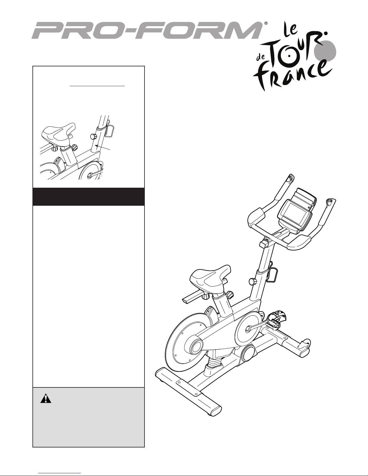
Model No. PFEVEX71316.0
Serial No.
Write the serial number in the space
above for reference.
Serial
Number
Decal
CUSTOMER SERVICE
UNITED KINGDOM
Call: 0330 123 1045
From Ireland: 053 92 36102
Website: www.iconsupport.eu
E-mail: csuk@iconeurope.com
Write:
ICON Health & Fitness, Ltd.
Unit 1D, The Gateway
Fryers Way, Silkwood Park
OSSETT
WF5 9TJ
UNITED KINGDOM
USER’S MANUAL
AUSTRALIA
Call: 1800 993 770
E-mail: australiacc@iconfitness.com
Write:
ICON Health & Fitness
PO Box 635
WINSTON HILLS NSW 2153
AUSTRALIA
CAUTION
Read all precautions and
instructions in this manual before
using this equipment. Keep this
manual for future reference.
www.iconeurope.com
Page 2
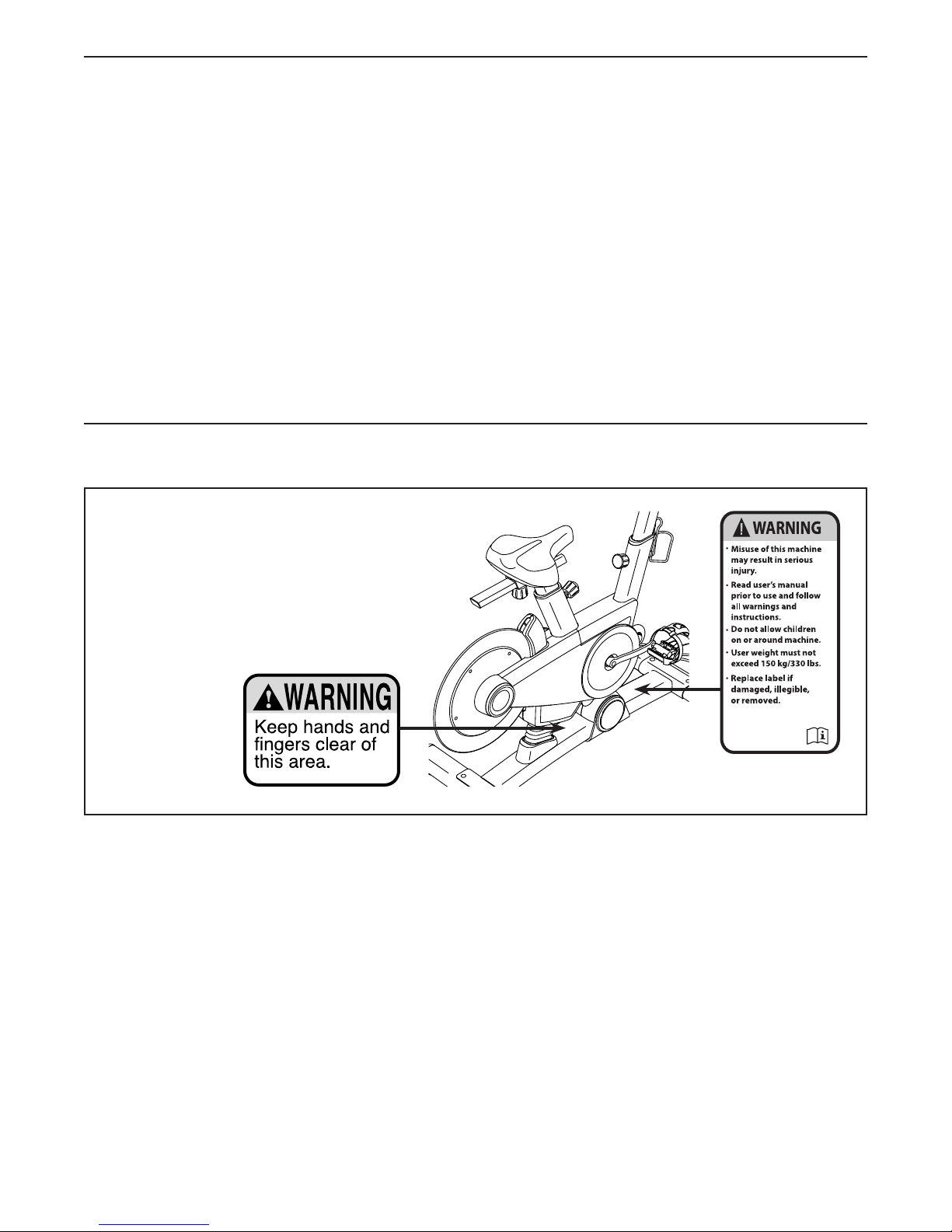
TABLE OF CONTENTS
WARNING DECAL PLACEMENT . . . . . . . . . . . . . . . . . . . . . . . . . . . . . . . . . . . . . . . . . . . . . . . . . . . . . . . . . . . . . . .2
IMPORTANT PRECAUTIONS ..................................................................3
BEFORE YOU BEGIN. . . . . . . . . . . . . . . . . . . . . . . . . . . . . . . . . . . . . . . . . . . . . . . . . . . . . . . . . . . . . . . . . . . . . . . .5
PART IDENTIFICATION CHART. . . . . . . . . . . . . . . . . . . . . . . . . . . . . . . . . . . . . . . . . . . . . . . . . . . . . . . . . . . . . . . .6
ASSEMBLY . . . . . . . . . . . . . . . . . . . . . . . . . . . . . . . . . . . . . . . . . . . . . . . . . . . . . . . . . . . . . . . . . . . . . . . . . . . . . . . .7
HOW TO USE THE EXERCISE BIKE. . . . . . . . . . . . . . . . . . . . . . . . . . . . . . . . . . . . . . . . . . . . . . . . . . . . . . . . . . . 13
MAINTENANCE AND TROUBLESHOOTING .....................................................25
EXERCISE GUIDELINES ....................................................................27
PART LIST. . . . . . . . . . . . . . . . . . . . . . . . . . . . . . . . . . . . . . . . . . . . . . . . . . . . . . . . . . . . . . . . . . . . . . . . . . . . . . . .28
EXPLODED DRAWING. . . . . . . . . . . . . . . . . . . . . . . . . . . . . . . . . . . . . . . . . . . . . . . . . . . . . . . . . . . . . . . . . . . . . .30
ORDERING REPLACEMENT PARTS. . . . . . . . . . . . . . . . . . . . . . . . . . . . . . . . . . . . . . . . . . . . . . . . . . . Back Cover
RECYCLING INFORMATION ......................................................... Back Cover
WARNING DECAL PLACEMENT
This drawing shows the location(s) of the warning
decal(s). If a decal is missing or illegible, see
the front cover of this manual and request a
free replacement decal. Apply the decal in the
location shown. Note: The decal(s) may not be
shown at actual size.
PROFORM is a registered trademark of ICON Health & Fitness, Inc. IFIT is a registered trademark of ICON
Health & Fitness, Inc. LE TOUR DE FRANCE is a registered trademark of Société du Tour de France. App Store
is a trademark of Apple Inc., registered in the U.S. and other countries. Android and Google Play are trademarks
of Google Inc. The BLUETOOTH® word mark and logos are registered trademarks of Bluetooth SIG, Inc. and are
used under license. IOS is a trademark or registered trademark of Cisco in the U.S. and other countries and is
used under license.
2
Page 3

IMPORTANT PRECAUTIONS
WARNING: To reduce the risk of burns, fire, electric shock, or injury to persons, read all
important precautions and instructions in this manual and all warnings on your exercise bike before
using your exercise bike. ICON assumes no responsibility for personal injury or property damage
sustained by or through the use of this product.
1. It is the responsibility of the owner to ensure
that all users of the exercise bike are adequately informed of all precautions.
2. Before beginning any exercise program,
consult your physician. This is especially
important for persons over age 35 or persons with pre-existing health problems.
3. The exercise bike is not intended for use by
persons with reduced physical, sensory, or
mental capabilities or lack of experience and
knowledge, unless they are given supervision or instruction about use of the exercise
bike by someone responsible for their safety.
4. Use the exercise bike only as described in
this manual.
5. The exercise bike is intended for home use
only. Do not use the exercise bike in a commercial, rental, or institutional setting.
6. Keep the exercise bike indoors, away from
moisture and dust. Do not put the exercise
bike in a garage or covered patio, or near
water.
8. Inspect and properly tighten all parts each
time the exercise bike is used. Replace any
worn parts immediately.
9. Keep children under age 13 and pets away
from the exercise bike at all times.
10. When connecting the power cord, plug the
power cord into a grounded circuit.
11. Do not modify the power cord or use an
adapter to connect the power cord to an
improper receptacle. Keep the power cord
away from heated surfaces. Do not use an
extension cord.
12. Do not operate the exercise bike if the power
cord or plug is damaged, or if the exercise
bike is not working properly.
13. DANGER: Always unplug the power
cord and press the power switch to the off
position when the exercise bike is not in
use and before cleaning the exercise bike.
Servicing other than the procedures in this
manual should be performed by an authorized service representative only.
7. Place the exercise bike on a level surface
with at least 2 ft. (0.6 m) of clearance around
the exercise bike. To protect the floor or
carpet from damage, place a mat under the
exercise bike.
14. Wear appropriate clothes while exercising;
do not wear loose clothes that could become
caught on the exercise bike. Always wear
athletic shoes for foot protection.
3
Page 4

15. The exercise bike should not be used
by persons weighing more than 330 lbs.
(150 kg).
16. Be careful when mounting and dismounting
the exercise bike.
SAVE THESE INSTRUCTIONS
17. Always keep your back straight while using
the exercise bike; do not arch your back.
18. Over exercising may result in serious injury
or death. If you feel faint, if you become short
of breath, or if you experience pain while
exercising, stop immediately and cool down.
4
Page 5
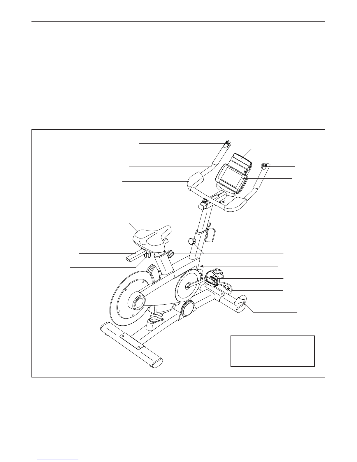
BEFORE YOU BEGIN
Congratulations for selecting the revolutionary
PROFORM® LE TOUR DE FRANCE® exercise bike.
The LE TOUR DE FRANCE exercise bike is unlike any
other exercise bike. With an incline system that allows
you to simulate actual terrain and an array of other
features, the LE TOUR DE FRANCE exercise bike is
designed to let you enjoy the outdoor cycling experience indoors.
For your benefit, read this manual carefully before
you use the exercise bike. If you have questions after
Incline Control
Handlebar
Armrest
Handlebar Carriage
reading this manual, please see the front cover of this
manual. To help us assist you, note the product model
number and serial number before contacting us. The
model number and the location of the serial number
decal are shown on the front cover of this manual.
Before reading further, please familiarize yourself with
the parts that are labeled in the drawing below.
Tablet Holder
Gear
Control
Console
Handlebar Knob
Seat
Seat Carriage
Seat Knob
Leveling Foot
*Water bottle is not included
Water Bottle Holder*
Post Knobs
Power Switch
Pedal/Strap
Power Cord
Wheel
Length: 4 ft. 11 in. (150 cm)
Width: 2 ft. 1 in. (64 cm)
Weight: 128 lbs. (58 kg)
5
Page 6
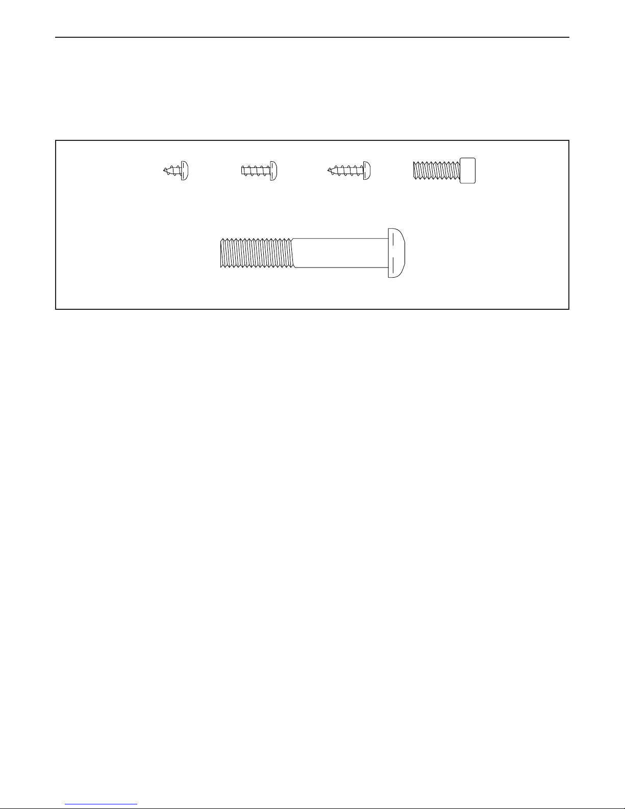
PART IDENTIFICATION CHART
Use the drawings below to identify the small parts needed for assembly. The number in parentheses below each
drawing is the key number of the part, from the PART LIST near the end of this manual. The number following
the key number is the quantity needed for assembly. Note: If a part is not in the hardware kit, check to see
whether it has been preassembled. Extra parts may be included.
#8 x 6mm
Screw (92)–1
#8 x 10mm
Screw (110)–2
M10 x 58mm Screw (74)–4
M4 x 12mm
Screw (94)–4
M6 x 16mm
Screw (103)–4
6
Page 7
ASSEMBLY
• Assembly requires two persons.
• Place all parts in a cleared area and remove the
packing materials. Do not dispose of the packing
materials until you complete all assembly steps.
• Left parts are marked “L” or “Left” and right parts
are marked “R” or “Right.”
• To identify small parts, see page 6.
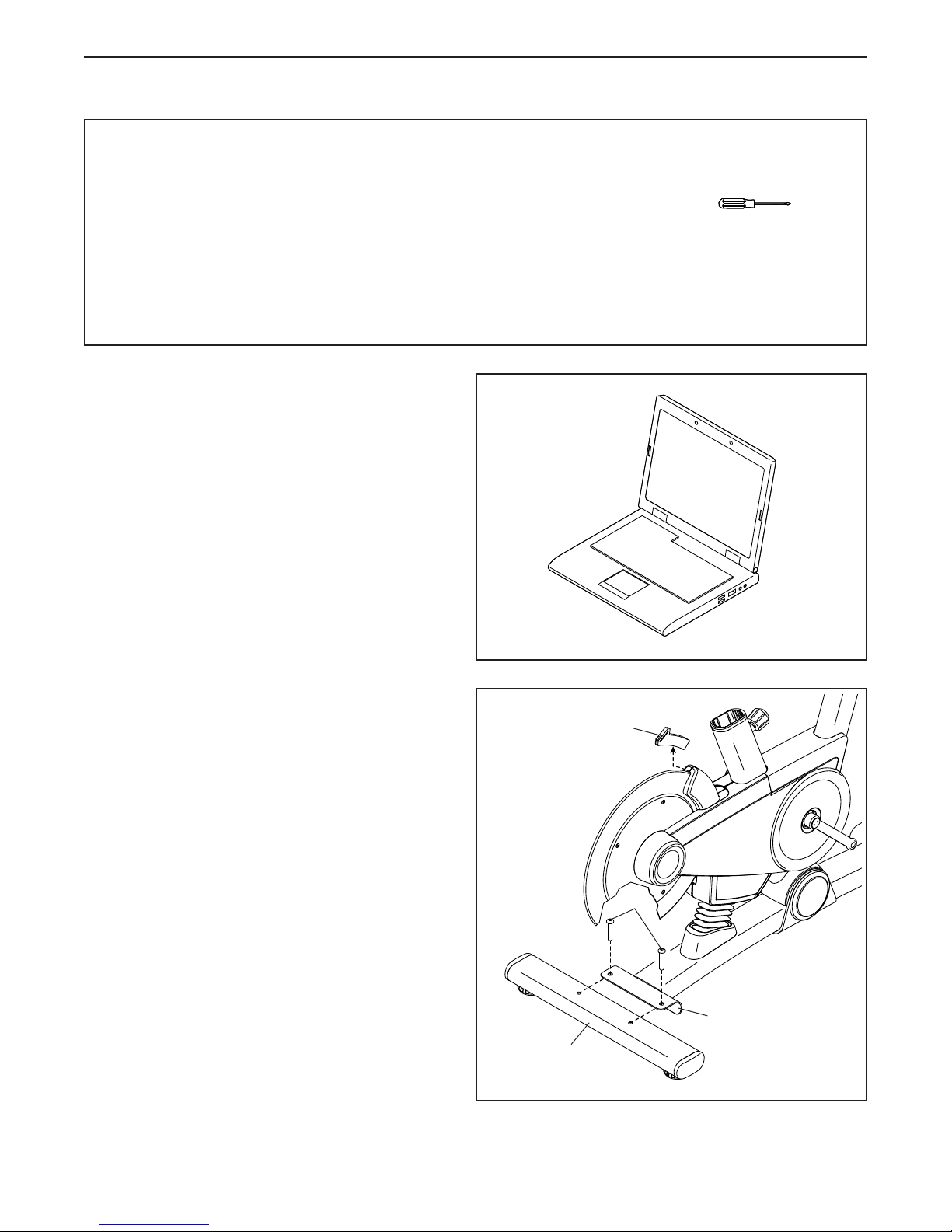
1. Go to www.iconsupport.eu on your computer
and register your product.
• activates your warranty
• saves you time if you ever need to contact
Customer Service
• allows us to notify you of upgrades and offers
Note: If you do not have internet access, call
Customer Service (see the front cover of this
manual) and register your product.
• In addition to the included tool(s), assembly
requires the following tools:
one Phillips screwdriver
Assembly may be easier if you have your own set
of wrenches. To avoid damaging parts, do not use
power tools.
1
2. Remove and discard the indicated shipping
insert (A). If there are shipping screws in
the Rear Stabilizer (23), remove and discard
them.
Attach the Rear Stabilizer (23) to the Base (1)
with two M10 x 58mm Screws (74).
2
A
74
1
23
7
Page 8
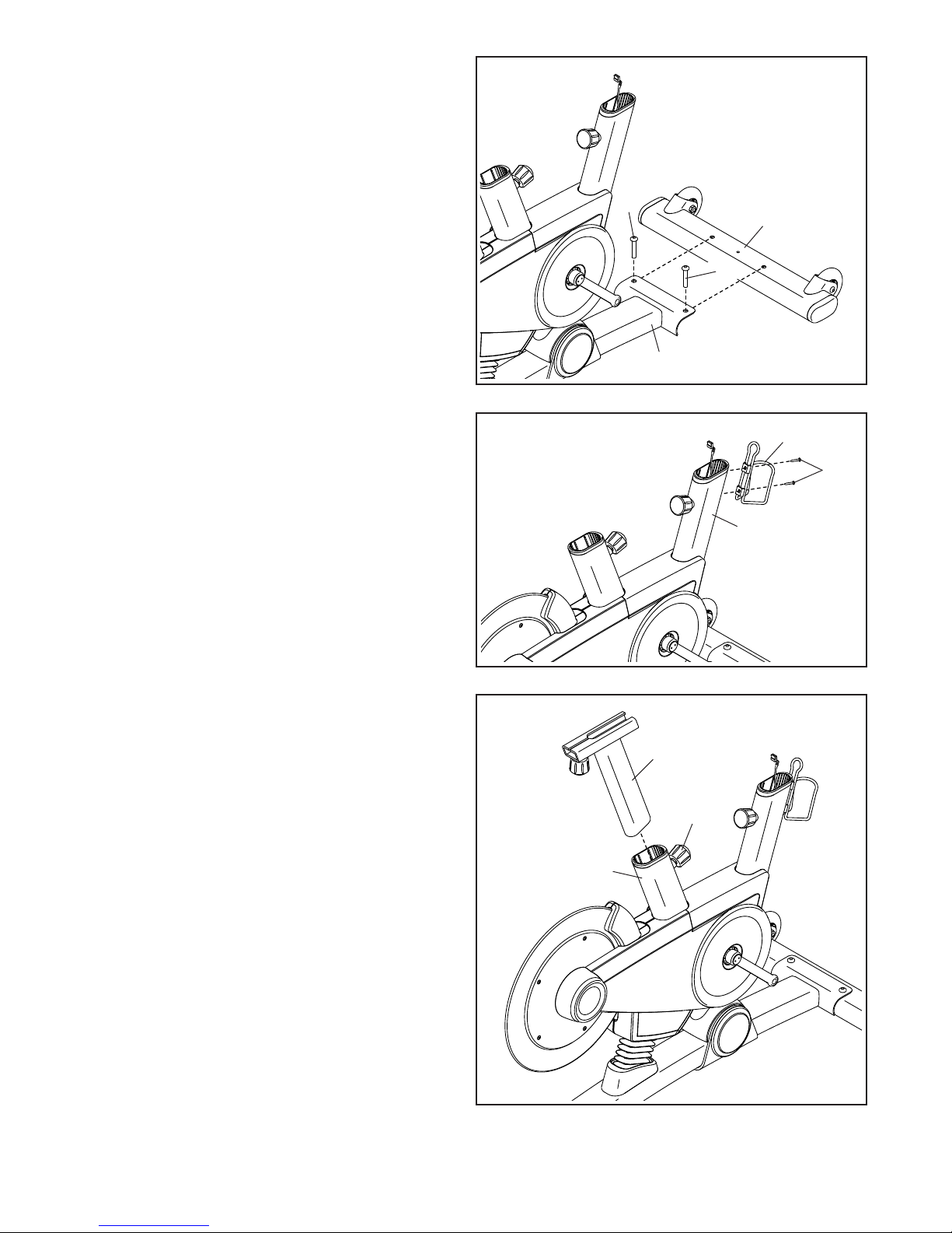
3. If there are shipping screws in the Front
Stabilizer (22), remove and discard them.
Attach the Front Stabilizer (22) to the Base (1)
with two M10 x 58mm Screws (74).
3
4. Attach the Water Bottle Holder (8) to the Frame
(2) with two #8 x 10mm Screws (110); start all
the Screws, and then tighten them.
74
1
4
22
74
8
110
2
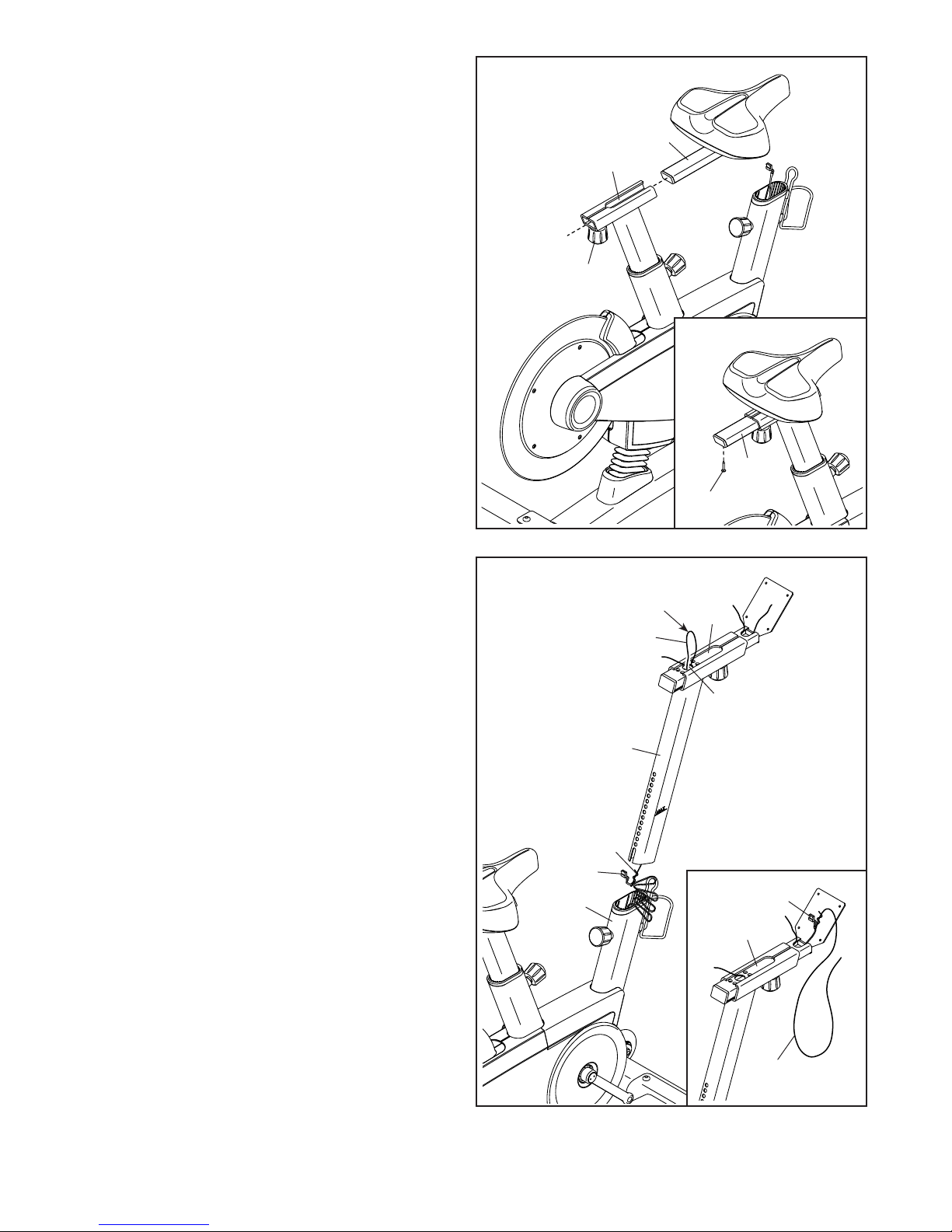
5. Locate the Post Knob (47) near the rear of the
Frame (2). Loosen the Post Knob, and then pull
it outward.
Next, insert the Seat Post (3) into the Frame (2),
and release the Post Knob (47) into one of the
adjustment holes in the Seat Post. Make sure
that the Post Knob is in an adjustment hole.
Then, tighten the Post Knob.
5
3
47
2
8
Page 9
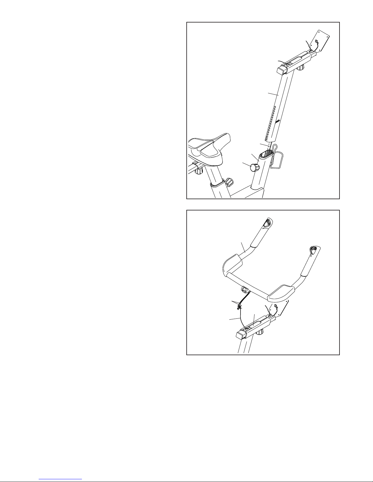
6. Loosen the Seat Knob (29), and then pull it
downward.
Next, insert the Seat Carriage (4) into the Seat
Post (3), and release the Seat Knob (29) into
one of the adjustment holes in the Seat Carriage.
Make sure that the Seat Knob is in an adjustment hole. Then, tighten the Seat Knob.
See the inset drawing. Tighten a #8 x 6mm
Screw (92) into the underside of the Seat
Carriage (4).
6
4
3
29
4
92
7. Have a second person hold the Handlebar Post
(6) near the Frame (2).
Locate the long wire tie (B) in the Handlebar
Post (6). Tie the lower end of the long wire tie to
the Main Wire (68).
Next, locate the middle of the long wire tie (B) in
the access hole (C) in the Handlebar Carriage
(105). In the indicated location (D), pull the long
wire tie upward until the end of the Main Wire
(68) is in the access hole.
See the inset drawing. Next, pull the free end
of the long wire tie until the Main Wire (68) is
routed through the Handlebar Carriage (105) as
shown. Then, untie and discard the long wire tie;
do not remove the short wire tie.
7
Avoid
pinching
the Main
Wire (68)
2
68
D
B
6
B
105
C
68
105
B
9
Page 10
8. Tip: Avoid pinching the Main Wire (68) during
this step.
Locate the Post Knob (47) near the front of the
Frame (2). Loosen the Post Knob, and then pull
it outward.
Next, insert the Handlebar Post (6) into the
Frame (2), and release the Post Knob (47) into
one of the adjustment holes in the Handlebar
Post. Make sure that the Post Knob is in an
adjustment hole. Then, tighten the Post Knob.
8
Avoid pinching the
Main Wire (68)
6
68
2
47
9. Have a second person hold the Handlebar (7)
near the Handlebar Carriage (105).
Locate the remaining wire tie (E) in the
Handlebar Carriage (105). Tie the indicated
end of the wire tie to the two wires (F) on the
Handlebar (7).
Next, pull the other end of the wire tie (E)
until the two wires (F) are routed through the
Handlebar Carriage (105). Then, untie and
discard the wire tie.
9
7
F
105
E
10
Page 11

10. Tip: Avoid pinching the wires during this
step.
Attach the Handlebar (7) to the Handlebar
Carriage (105) with four M6 x 16mm Screws
(103); start all the Screws, and then tighten
them.
10
Avoid pinching
the wires
103
7
105
11. Tip: Avoid pinching the wires during this
step.
Have a second person hold the Console (9) near
the Handlebar Carriage (105).
Connect the console wires to the Main Wire (68)
and to the two wires (F) from the Handlebar (7);
make sure to connect the console wire that
has an “L” tag to the wire that has an “L” tag,
and connect the console wire that has an “R”
tag to the wire that has an “R” tag. Insert the
excess wire into the Handlebar Carriage (105).
Then, attach the Console (9) to the Handlebar
Carriage (105) with four M4 x 12mm Screws
(94); start all the Screws, and then tighten
them.
11
9
68
7
Avoid pinching
the wires
105
F
94
11
Page 12

12. Identify the Right Pedal (62).
Using the included flat wrench tool, firmly
tighten the Right Pedal (62) clockwise into the
Right Crank Arm (64).
Firmly tighten the Left Pedal (61) coun-
terclockwise into the Left Crank Arm (not
shown). IMPORTANT: You must turn the Left
Pedal counterclockwise to attach it.
12
61
To adjust the straps on the Pedals (61, 62), see
HOW TO USE THE PEDALS on page 15.
13. After the exercise bike is assembled, inspect it to make sure that it is assembled correctly and that it
functions properly. Make sure that all parts are properly tightened before you use the exercise bike.
Extra parts may be included. Place a mat beneath the exercise bike to protect the floor.
64
62
12
Page 13

HOW TO USE THE EXERCISE BIKE
FR/SP
UK
UK
HOW TO PLUG IN THE POWER CORD
This product must be earthed. If it should
malfunction or break down, earthing provides a path of
least resistance for electric current to reduce the risk
of electric shock. This product’s power cord has an
equipment-earthing conductor and an earthing plug.
IMPORTANT: If the power cord is damaged, it must
be replaced with a manufacturer-recommended
power cord.
DANGER: Improper connection of
the equipment-earthing conductor can result
in an increased risk of electric shock. Check
with a qualified electrician or serviceman if
you are in doubt as to whether the product
is properly earthed. Do not modify the plug
provided with the product—if it will not fit
the outlet, have a proper outlet installed by a
qualified electrician
Follow the steps below to plug in the power cord.
1. Plug the indicated end of the power cord into the
socket on the frame.
Socket on Frame
Power Cord
2. Plug the power cord into an appropriate outlet that
is properly installed and earthed in accordance with
all local codes and ordinances.
UK
Outlet
Australia
Outlet
13
Page 14
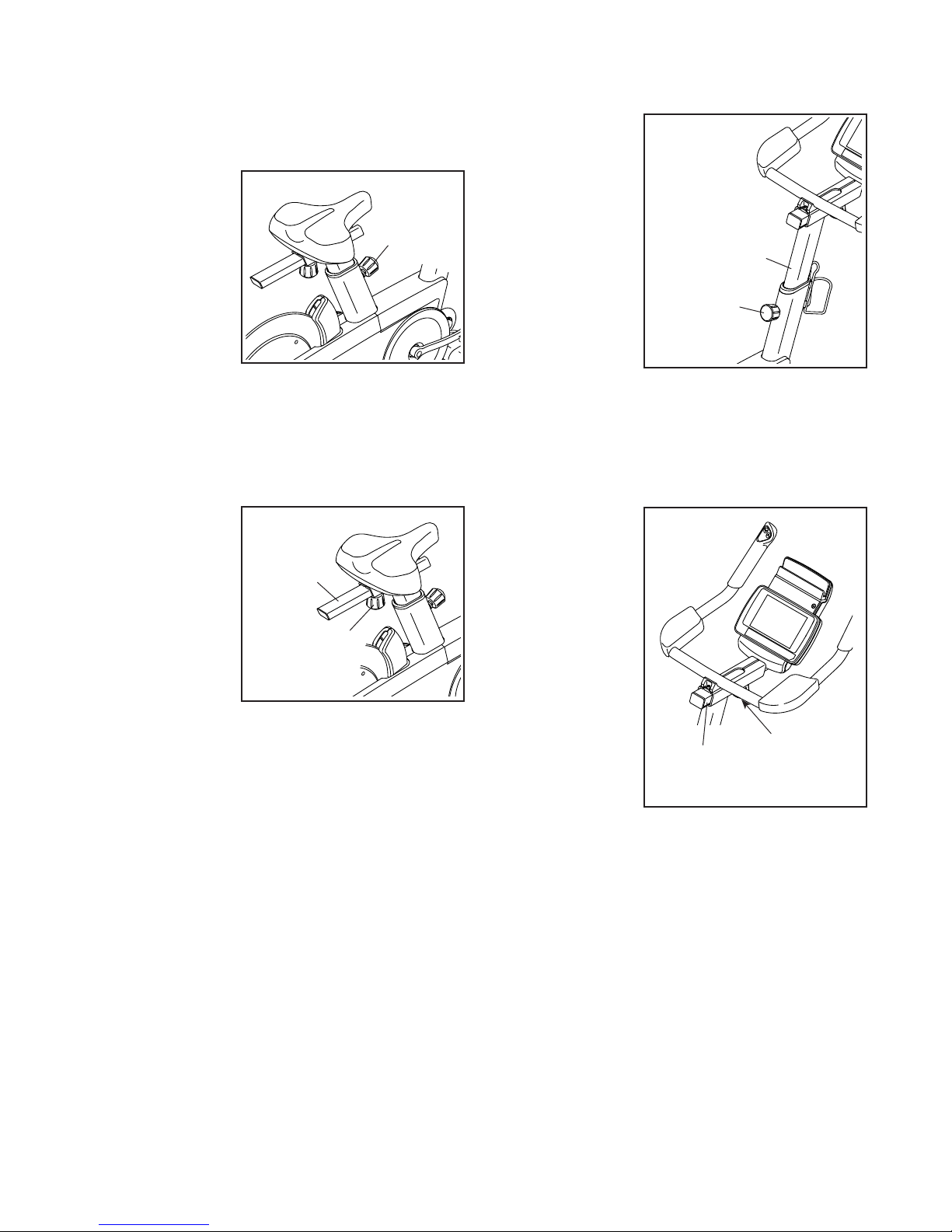
HOW TO ADJUST THE HEIGHT OF THE SEAT
For effective exercise, the seat should be at the proper
height. As you pedal, there should be a slight bend in
your knees when the pedals are in the lowest position.
To adjust the
height of the seat,
rst loosen the
post knob and
pull it outward.
Then, move the
seat post upward
or downward,
release the post
knob into an
adjustment hole in
the seat post, and
rmly tighten the post knob. Make sure that the post
knob is engaged in an adjustment hole.
Post
Knob
HOW TO ADJUST THE HEIGHT OF THE
HANDLEBAR
To adjust the
height of the handlebar, first loosen
the post knob and
pull it outward.
Then, move the
handlebar post
upward or downward, release the
post knob into an
adjustment hole
in the handlebar
post, and firmly
tighten the post
knob. Make sure
that the post knob is engaged in an adjustment
hole.
Post Knob
Handlebar
Post
HOW TO ADJUST THE HORIZONTAL POSITION OF
THE SEAT
To adjust the
horizontal position
of the seat, rst
loosen the seat
knob and pull it
downward. Then,
move the seat carriage forward or
backward, release
the seat knob into
an adjustment
hole in the seat
carriage, and rmly tighten the seat knob. Make sure
that the seat knob is engaged in an adjustment
hole.
Seat
Carriage
Seat
Knob
HOW TO ADJUST THE HORIZONTAL POSITION OF
THE HANDLEBAR
To adjust the
horizontal position
of the handlebar,
rst loosen the
handlebar knob.
Then, move the
handlebar carriage forward or
backward, and
rmly tighten the
handlebar knob.
Handlebar
Carriage
Handlebar
Knob
14
Page 15

HOW TO USE THE PEDALS
HOW TO USE THE TABLET HOLDER
To use the pedals,
insert your shoes
into the toe cages,
and pull the ends
of the toe straps.
To adjust the toe
straps, press and
hold the tabs on
the buckles, adjust
the toe straps
to the desired
position, and then
release the tabs.
HOW TO LEVEL THE EXERCISE BIKE
If the exercise
bike rocks slightly
on your floor
during use, turn
one or both of
the leveling feet
beneath the rear
stabilizer until the
rocking motion is
eliminated.
Leveling
Feet
Toe
Cage
IMPORTANT: The tablet holder is designed for use
with most small tablets. Do not place any other
electronic device or object into the tablet holder.
To insert a tablet
into the tablet
holder, set the
bottom edge of
the tablet in the
tray. Make sure
that the tablet is
firmly secured in
the tablet holder.
Reverse these
actions to remove
the tablet from the
tablet holder.
Tablet
Holder
15
Page 16

CONSOLE DIAGRAM
FEATURES OF THE CONSOLE
The advanced console offers an array of features
designed to make your workouts more effective and
enjoyable.
When you use the manual mode of the console, you
can change the incline (resistance) of the exercise bike
and change gears with the touch of a button.
You can also create custom manual workouts with
alternating high- and low-intensity intervals.
While you exercise, the console will display continuous
exercise feedback. You can also measure your heart
rate using an optional heart rate monitor. See page
23 for information about purchasing an optional
chest heart rate monitor.
You can also connect your smart device to the console
and use an iFit® app to record and track your workout
information.
The console also offers a selection of onboard workouts. Each workout automatically changes the incline
(resistance) of the exercise bike and allows you to
change gears to maintain your pedaling cadence.
The watts workout changes the resistance of the
pedals to keep your watts output near a target level.
You can also listen to your favorite workout music or
audio books with the console sound system while you
exercise.
To turn on the power, see page 17. To use the
manual mode, see page 17. To use an onboard
workout, see page 20. To use the watts workout,
see page 21.
To use the sound system, see page 22. To connect your smart device to the console, see page
23. To connect your heart rate monitor to the
console, see page 24. To use the settings mode,
see page 24.
The console can display speed and distance in either
miles or kilometers and weight in either pounds or kilo-
grams. To nd which unit of measurement is selected,
see step 3 on page 24.
If there is a sheet of plastic on the display, remove the
plastic.
16
Page 17

HOW TO TURN ON THE POWER
3. Enter your weight.
IMPORTANT: If the exercise bike has been exposed
to cold temperatures, allow it to warm to room temperature before you turn on the power. If you do
not do this, you may damage the console displays
or other electrical components.
Plug in the power cord (see
HOW TO PLUG IN THE
POWER CORD on page
13). Next, locate the
power switch on the frame
near the power cord. Press
the power switch to the
reset position.
The display will then turn on and the console will be
ready for use.
Note: When you turn on the power for the first time,
the incline system may calibrate automatically. The
exercise bike will move forward and backward as it
calibrates. When the exercise bike stops moving, the
incline system is calibrated.
IMPORTANT: If the incline system does not calibrate automatically, see step 3 on page 24 and
manually calibrate the incline system.
HOW TO USE THE MANUAL MODE
1. Begin pedaling or press any button on the
console to turn on the console.
See HOW TO TURN ON THE POWER on
page 17.
Reset
Position
Press the Wt increase
and decrease buttons to
enter your weight.
Note: The console will use your weight to calcu-
late your approximate power output and calories
burned. If you do not enter your weight, the console
will use a default value to calculate your power
output and calories burned.
4. Change the incline (resistance) of the exercise
bike as desired.
Begin pedaling to start the manual mode.
As you pedal, you can
change the incline
(resistance) of the exercise bike. To change
the incline level, press
the Incline increase
and decrease buttons on the console or press the
Incline increase and decrease buttons on the left
handlebar.
Note: After you press a button, it will take a
moment for the exercise bike to reach the selected
incline level. You will hear the incline motor
while the incline is changing. This is normal.
CAUTION: The exercise bike can move to a
broad range of incline levels. Hold the handlebars and be prepared for the exercise bike to
move when you change the incline.
2. Select the manual mode.
When you turn on the console, the manual mode
will be selected automatically.
If you have selected a workout, reselect the manual
mode by pressing the Manual Control button.
17
Page 18

5. Change gears as desired.
Note: The exercise bike has simulated gears; there
are no actual gears.
As you pedal, you
can change gears to
make pedaling easier
or harder. To change
gears, press the Gears
increase and decrease
buttons on the console or press the Gears increase
and decrease buttons on the right handlebar.
Note: After you press a button, it will take a
moment for the exercise bike to change to the
selected gear.
6. Do interval training, if desired.
As you exercise, you can alternate between
intervals of low-intensity (recovery) exercise
and intervals of high-intensity (work) exercise, if
desired.
To create a recovery interval, first adjust the incline
to the desired level. Then, press and hold the
Recovery button until two tones sound to save the
interval setting.
7. Follow your progress with the power ring, and
set a power output target, if desired.
The power ring
will provide a
visual representation of your power
output in watts
per kilogram of
body weight. As
your power output increases or
decreases, a solid
bar will appear or
disappear in the
power ring.
To set a power output target, press the Watts/Kg
increase and decrease buttons until the desired
power output target appears in the display.
If you set a power output target during the
manual mode, a flashing indicator will appear in
the power ring to indicate your power output target.
As you exercise, adjust your pedaling speed, the
gears, and/or the incline level to keep your power
output near the power output target.
Solid Bar
To create a work interval, first adjust the incline to
the desired level. Then, press and hold the Work
button until two tones sound to save the interval
setting.
As you exercise, press the Recovery and Work
buttons as desired to alternate between the saved
interval settings. After you press a button, the
incline level of the exercise bike will automatically
adjust to the level that you saved.
To change the interval settings at any time during
your workout, simply repeat this step.
Actual Power
Output
To change the power output target at any time
during your workout, simply repeat the actions
above.
Power Output
Target
18
Page 19

IMPORTANT: The power output target is
intended only to provide motivation. Make
sure to pedal at a speed, a gear setting, and an
incline level that is comfortable for you.
During an onboard workout, the power ring will
show the preset power output target for each segment of the workout (see step 4 on page 20).
8. Follow your progress with the display.
The display can show the following workout
information:
Calories (CALS)—The approximate number of
calories you have burned.
Distance (MI or KI)—The distance that you have
pedaled in miles or kilometers. When the manual
mode is selected, the distance will count up. When
an onboard workout is selected, the distance will
count down.
Gear—The number of the currently selected gear.
Note: This workout information will appear for a few
seconds each time you change gears.
RPM—Your pedaling speed in revolutions per
minute (rpm).
Speed—Your pedaling speed in miles or kilometers
per hour.
Time—The elapsed time.
Watts—Your power output in watts.
Press the Display button repeatedly to view the
desired workout information in the display.
Scan mode—The
console also has
a scan mode that
will display workout information in
a repeating cycle.
To select the scan
mode, press the
Display button
repeatedly until
the word SCAN
appears in the
display.
Incline (% GRD)—The incline level of the exercise
bike.
Pace—Your pedaling speed in minutes per mile or
minutes per kilometer.
Pulse (heart symbol)—Your heart rate when you
wear a compatible heart rate monitor (see step 9).
To pause the console, simply stop pedaling. When
the console is paused, the time will flash in the
display. To continue your workout, simply resume
pedaling.
Note: The console can show weight, pedaling
speed, and distance in standard or metric units of
measurement. To change the unit of measurement,
see THE SETTINGS MODE on page 24.
19
Page 20

9. Wear a heart rate monitor and measure your
heart rate if desired.
You can wear an optional heart rate monitor to
measure your heart rate. For more informa-
tion about the optional heart rate monitor, see
page 23. Note: The console is compatible with
BLUETOOTH® Smart heart rate monitors.
When your heartbeat is detected, your heart rate
will be shown in the pulse display.
10. When you are nished exercising, unplug the
power cord.
If the pedals do not move for several seconds, the
console will pause.
If the pedals do not move for several minutes and
the buttons are not pressed, the console will turn
off and the display will be reset.
When you are nished exercising, press the power
switch to the off position and unplug the power
cord. IMPORTANT: If you do not do this, the
electrical components on the exercise bike may
wear prematurely.
2. Enter your weight.
Press the Wt increase
and decrease buttons to
enter your weight.
Note: The console will use your weight to calcu-
late your approximate power output and calories
burned. If you do not enter your weight, the console
will use a default value to calculate your power
output and calories burned.
3. Select an onboard workout.
To select an onboard
workout, press the
Tempo Apps button or
the Interval Apps button repeatedly until the
name of the desired
workout appears in the display. A few seconds
after you press a button, the total distance of the
workout will appear in the display.
4. Start the workout.
HOW TO USE AN ONBOARD WORKOUT
1. Begin pedaling or press any button on the
console to turn on the console.
See HOW TO TURN ON THE POWER on
page 17.
Begin pedaling to start the workout.
Each workout is divided into one-minute segments.
One incline level and one power output target are
programmed for each segment. Note: The same
incline level and/or power output target may be programmed for consecutive segments.
At the end of each segment of the workout, a
series of tones will sound. The incline level for the
next segment will appear in the display for a few
seconds to alert you. The incline level will then
change.
20
Page 21

The power ring will show a flashing indicator that
represents the power output target for the segment.
The solid bar represents your actual power output
Note: In the power ring, power output is displayed
in watts per kilogram of body weight.
6. Measure your heart rate if desired.
See step 9 on page 20.
7. When you are nished exercising, unplug the
power cord.
Actual Power
Output
As you exercise, keep your power output near the
power output target for the current segment by
adjusting your pedaling speed and/or the gears.
IMPORTANT: The power output target is
intended only to provide motivation. Make
sure to pedal at a speed, a gear setting, and an
incline level that is comfortable for you.
If the incline level for the current segment is too
high or too low, you can manually override the setting by pressing the Incline buttons. IMPORTANT:
When the current segment of the workout ends,
the exercise bike will automatically adjust
to the incline level programmed for the next
segment.
To pause the console, simply stop pedaling. When
the console is paused, the time will flash in the
display. To continue your workout, simply resume
pedaling.
5. Follow your progress with the display.
Power Output
Target
See step 10 on page 20.
HOW TO USE THE WATTS WORKOUT
1. Begin pedaling or press any button on the
console to turn on the console.
See HOW TO TURN ON THE POWER on
page 17.
2. Enter your weight.
Press the Wt increase
and decrease buttons to
enter your weight.
Note: The console will use your weight to calcu-
late your approximate power output and calories
burned. If you do not enter your weight, the console
will use a default value to calculate your power
output and calories burned.
3. Select the watts workout.
To select the watts
workout, press the
Tempo Apps button
repeatedly until you
come to the last workout
in the menu. The name
of the watts workout will appear in the display. A
few seconds later, the target watts setting for the
workout will appear in the display.
See step 8 on page 19.
21
Page 22

4. Enter a target watts setting.
To enter a target watts
setting, press the
Watts/Kg increase and
decrease buttons.
5. Start the workout.
Begin pedaling to start the workout.
During the workout, your actual watts output will
appear in the display. The console will regularly
compare your watts output to the target watts
setting.
To change the target watts setting at any
time during the workout, press the Watts/Kg
increase and decrease buttons.
The workout will continue in this way indefinitely. To
pause the console, simply stop pedaling. When the
console is paused, the time will flash in the display.
To continue your workout, simply resume pedaling.
6. Follow your progress with the display.
See step 8 on page 19.
7. Measure your heart rate if desired.
See step 9 on page 20.
As you pedal, keep your watts output near the
target watts setting by adjusting your pedaling
speed.
Note: During the watts workout, the resistance of
the pedals will adjust automatically. Do not press
the Gears buttons during the watts workout.
Pressing the Gears buttons will have no effect
on your watts output.
Note: You can change the incline of the exercise
bike as desired. However, changing the incline
during the watts workout will have no effect on
your watts output.
If your watts output is too far below or above the
target watts setting, the resistance of the pedals
will automatically increase or decrease to bring
your watts output closer to the target watts setting.
8. When you are nished exercising, unplug the
power cord.
See step 10 on page 20.
HOW TO USE THE SOUND SYSTEM
To play music or audio books through the console
sound system while you exercise, plug a 3.5 mm male
to 3.5 mm male audio cable (not included) into the
jack on the console and into a jack on your personal
audio player; make sure that the audio cable is fully
plugged in. Note: To purchase an audio cable, see
your local electronics store.
Next, press the play button on your personal audio
player. Adjust the volume level using the volume
control on your personal audio player.
22
Page 23

THE OPTIONAL CHEST HEART RATE MONITOR
Whether your
goal is to
burn fat or to
strengthen your
cardiovascular
system, the key
to achieving the
best results is
to maintain the
proper heart
rate during your
workouts. The optional chest heart rate monitor will
enable you to continuously monitor your heart rate
while you exercise, helping you to reach your personal
fitness goals. To purchase a chest heart rate moni-
tor, please see the front cover of this manual.
Note: The console is compatible with all BLUETOOTH
Smart heart rate monitors.
HOW TO CONNECT YOUR SMART DEVICE TO THE
CONSOLE
The console supports BLUETOOTH connections to
smart devices via the iFit app and to compatible heart
rate monitors. Note: Other BLUETOOTH connections
are not supported.
1. Download and install the iFit app on your smart
device.
Then, open the iFit app and follow the instructions
to set up an iFit account and customize settings.
2. Connect your smart device to the console.
Follow the instructions in the iFit app to connect
your smart device to the console.
When a connection is established, the LED on the
console will flash blue. Press the Bluetooth Smart
button on the console to confirm the connection;
the LED on the console will then turn solid blue.
3. Record and track your workout information.
Follow the instructions in the iFit app to record and
track your workout information.
4. Disconnect your smart device from the console
if desired.
To disconnect your smart device from the console,
press and hold the Bluetooth Smart button on the
console for 5 seconds; the LED on the console will
light while the button is held and turn off when the
button is released.
Note: All BLUETOOTH connections between the
console and other devices (including any smart
devices, heart rate monitors, and so forth) will be
disconnected.
On your iOS® or Android™ smart device, open the
App Store℠ or the Google Play™ store, search for
the free iFit app, and then install the app on your
smart device. Make sure that the BLUETOOTH
option is enabled on your smart device.
23
Page 24

HOW TO CONNECT YOUR HEART RATE MONITOR
TO THE CONSOLE
The console is compatible with all BLUETOOTH Smart
heart rate monitors.
To connect your BLUETOOTH Smart heart rate monitor to the console, press the Bluetooth Smart button
on the console. When a connection is established, the
LED on the console will flash red twice.
Note: If there is more than one compatible heart rate
monitor near the console, the console will connect to
the heart rate monitor with the strongest signal.
To disconnect your heart rate monitor from the console, press and hold the Bluetooth Smart button on the
console for 5 seconds; the LED on the console will light
while the button is held and turn off when the button is
released.
Note: All BLUETOOTH connections between the console and other devices (including any smart devices,
heart rate monitors, and so forth) will be disconnected.
THE SETTINGS MODE
1. Select the settings mode.
To select the settings mode, press and hold down
the Manual Control button until the settings mode
information appears in the display.
2. Navigate the settings mode.
Press the Tempo Apps button repeatedly until the
desired settings option appears in the display.
The console can show
weight, pedaling speed,
and distance in standard or metric units of
measurement. An E for
English miles or an M
for metric kilometers will appear in the display. To
change the unit of measurement, press the Interval
Apps button repeatedly.
Calibrate the Incline
System—The words
INC UPDN will appear
in the display.
To calibrate the incline system, press the Incline
increase or decrease button. The exercise bike
will automatically move forward and backward to
the maximum incline and decline levels, and then
return to the starting position. This will calibrate the
incline system.
IMPORTANT: Keep pets, feet, and other objects
away from the exercise bike while the incline
system is calibrating.
View Usage
Information—The
display will alternate
showing the total time
(in hours) that the
console has been used
since the exercise bike was purchased and the
total distance (in miles or kilometers) that the exercise bike has been pedaled.
4. Exit the settings mode.
3. Change settings as desired.
Change the Unit of Measurement—The display
will alternate showing the console version number
and the unit of measurement.
Press the Tempo Apps button repeatedly to exit the
settings mode.
24
Page 25
MAINTENANCE AND TROUBLESHOOTING
HOW TO MAINTAIN THE EXERCISE BIKE
Regular maintenance is important for optimal
performance and to reduce wear. Inspect and properly
tighten all parts each time the exercise bike is used.
Replace any worn parts immediately.
To clean the exercise bike, use a damp cloth and a
small amount of mild detergent. IMPORTANT: To
avoid damage to the console, keep liquids away
from the console and keep the console out of
direct sunlight.
INCLINE SYSTEM TROUBLESHOOTING
If the exercise bike does not move to the correct incline
or decline level, see step 3 on page 24 and calibrate
the incline system.
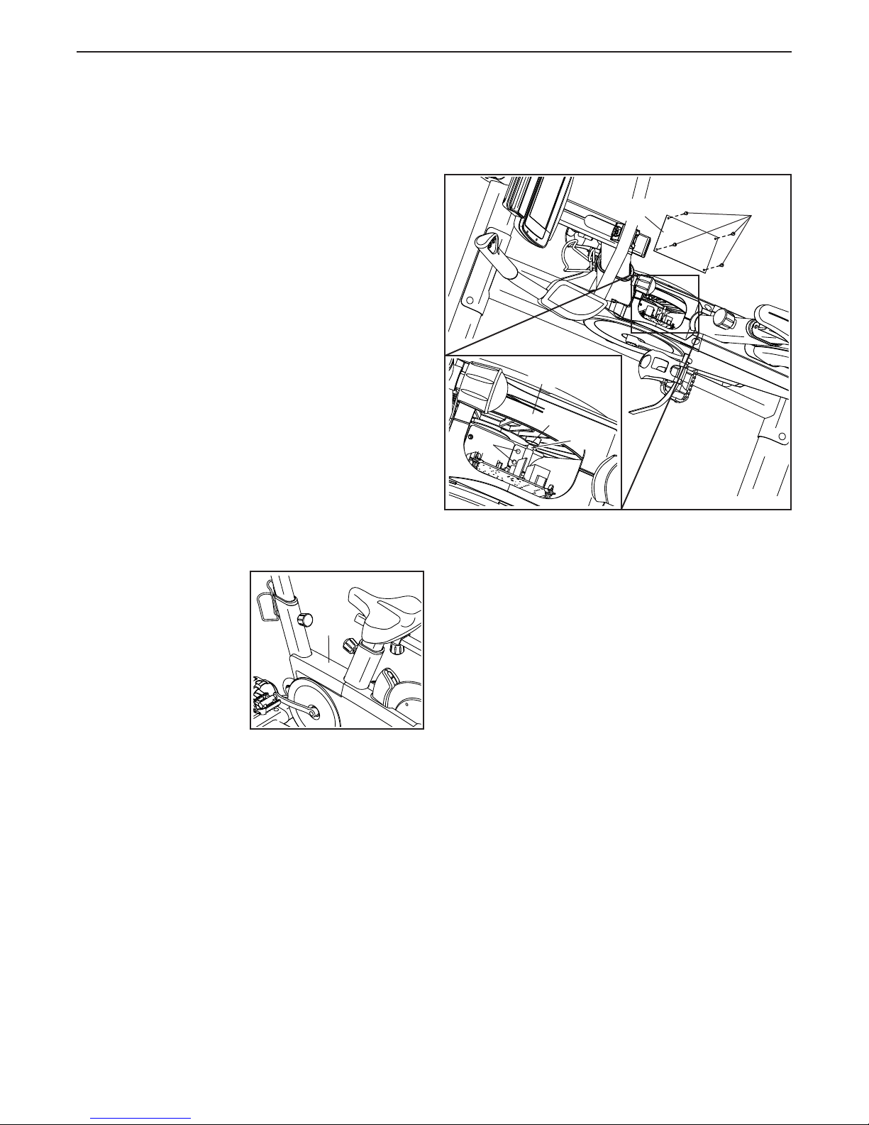
HOW TO ADJUST THE REED SWITCH
If the console does not display correct feedback, the
reed switch should be adjusted.
To adjust the reed switch, first press the power switch
to the off position and unplug the power cord.
Then, use a standard
screwdriver to remove
the Shield Cover (10)
from the exercise bike.
10
Next, remove the four #8 x 1/2” Screws (95) and the
Electronics Shield (98). Then, locate the Reed Switch
(35), and loosen the two #8 x 19mm Tek Screws (97).
98
53
55
97
Next, rotate the Crank Pulley (53) until a Pulley
Magnet (55) is aligned with the Reed Switch (35).
Slide the Reed Switch slightly toward or away from
the Pulley Magnet. Then, retighten the #8 x 19mm Tek
Screws (97).
Plug in the power cord and press the power switch to
the reset position. Rotate the Crank Pulley (53) for a
moment. Repeat these actions, if necessary, until the
console displays correct feedback.
35
95
When the reed switch is correctly adjusted, reattach
the electronics shield and the shield cover. Then, plug
in the power cord.
25
Page 26

HOW TO ADJUST THE DRIVE BELT
If the pedals slip while you are pedaling, the drive
belt may need to be adjusted.
To adjust the drive belt, first press the power switch
to the off position and unplug the power cord.
Next, locate the access hole (G) in the underside
of the Right Shield (12). Insert a hex key into the
access hole, and tighten the Idler Adjustment Screw
(not shown) slightly.
Then, plug in the power cord and press the power
switch to the reset position. Pedal the exercise bike
for a moment. Repeat these actions, if necessary,
until the pedals no longer slip while you are pedaling.
66
G
12
26
Page 27

EXERCISE GUIDELINES
WARNING: Before beginning this
or any exercise program, consult your physician. This is especially important for persons
over age 35 or persons with pre-existing
health problems.
Aerobic Exercise—If your goal is to strengthen your
cardiovascular system, you must perform aerobic
exercise, which is activity that requires large amounts
of oxygen for prolonged periods of time. For aerobic
exercise, adjust the intensity of your exercise until your
heart rate is near the highest number in your training
zone.
These guidelines will help you to plan your exercise
program. For detailed exercise information, obtain a
reputable book or consult your physician. Remember,
proper nutrition and adequate rest are essential for
successful results.
EXERCISE INTENSITY
Whether your goal is to burn fat or to strengthen your
cardiovascular system, exercising at the proper intensity is the key to achieving results. You can use your
heart rate as a guide to find the proper intensity level.
The chart below shows recommended heart rates for
fat burning and aerobic exercise.
To find the proper intensity level, find your age at the
bottom of the chart (ages are rounded off to the nearest ten years). The three numbers listed above your
age define your “training zone.” The lowest number is
the heart rate for fat burning, the middle number is the
heart rate for maximum fat burning, and the highest
number is the heart rate for aerobic exercise.
Burning Fat—To burn fat effectively, you must exercise at a low intensity level for a sustained period of
time. During the first few minutes of exercise, your
body uses carbohydrate calories for energy. Only after
the first few minutes of exercise does your body begin
to use stored fat calories for energy. If your goal is to
burn fat, adjust the intensity of your exercise until your
heart rate is near the lowest number in your training
zone. For maximum fat burning, exercise with your
heart rate near the middle number in your training
zone.
HOW TO MEASURE YOUR HEART RATE
To measure your heart
rate, exercise for at least
four minutes. Then, stop
exercising and place
two fingers on your
wrist as shown. Take a
six-second heartbeat
count, and multiply the
result by 10 to find your heart rate. For example, if your
six-second heartbeat count is 14, your heart rate is 140
beats per minute.
WORKOUT GUIDELINES
Warming Up—Start with 5 to 10 minutes of stretch-
ing and light exercise. A warm-up increases your body
temperature, heart rate, and circulation in preparation
for exercise.
Training Zone Exercise—Exercise for 20 to 30 minutes with your heart rate in your training zone. (During
the first few weeks of your exercise program, do not
keep your heart rate in your training zone for longer
than 20 minutes.) Breathe regularly and deeply as you
exercise; never hold your breath.
Cooling Down—Finish with 5 to 10 minutes of stretching. Stretching increases the flexibility of your muscles
and helps to prevent post-exercise problems.
EXERCISE FREQUENCY
To maintain or improve your condition, complete three
workouts each week, with at least one day of rest
between workouts. After a few months of regular exercise, you may complete up to five workouts each week,
if desired. Remember, the key to success is to make
exercise a regular and enjoyable part of your everyday
life.
27
Page 28

PART LIST
Key No. Qty. Description Key No. Qty. Description
Model No. PFEVEX71316.0 R0316A
1 1 Base
2 1 Frame
3 1 Seat Post
4 1 Seat Carriage
5 1 Seat
6 1 Handlebar Post
7 1 Handlebar
8 1 Water Bottle Holder
9 1 Console
10 1 Shield Cover
11 1 Left Shield
12 1 Right Shield
13 2 Shield Disc
14 1 Right Magnet Cover
15 1 Left Magnet Cover
16 1 Front Pivot Cover
17 1 Rear Pivot Cover
18 1 Base Shield
19 1 Flexible Cover
20 2 Pivot Ring
21 2 Pivot Disc
22 1 Front Stabilizer
23 1 Rear Stabilizer
24 4 Stabilizer Cap
25 2 Leveling Foot
26 2 Foot
27 2 Wheel
28 2 Seat Carriage Cap
29 1 Seat Knob
30 1 Lift Motor
31 1 Resistance Motor
32 1 Resistance Magnet
33 1 Arm
34 1 Magnet Axle
35 1 Reed Switch/Wire
36 1 Clamp
37 1 Idler Pulley
38 1 Idler Bolt
39 1 Idler Adjustment Screw
40 1 Flywheel Ring
41 1 Flywheel Hub
42 1 Flywheel Axle
43 1 Flywheel Spacer
44 1 Thrust Washer
45 1 Flywheel Pulley
46 2 Post Bushing
47 2 Post Knob
48 1 Power Switch
49 1 Grommet
50 1 Control Board
51 1 Board Bracket
52 4 Standoff
53 1 Crank Pulley
54 1 Crank
55 2 Pulley Magnet
56 4 M8 x 16mm Screw
57 2 Bearing
58 1 Snap Ring
59 2 Frame Bushing
60 1 Pivot Axle
61 1 Left Pedal
62 1 Right Pedal
63 1 Left Crank Arm
64 1 Right Crank Arm
65 2 Crank Arm Cap
66 1 Drive Belt
67 1 Power Cord
68 1 Main Wire
69 1 Left Armrest
70 1 Left Grip/Wire
71 3 3/8" Jam Nut
72 1 Right Armrest
73 2 1/4" x 32mm Screw
74 4 M10 x 58mm Screw
75 2 5/16" x 1 3/4" Bolt
76 2 5/16" Locknut
77 1 M10 x 35mm Hex Screw
78 2 5/16" x 17mm Flange Screw
79 5 M8 x 30mm Screw
80 5 M8 Nut
81 1 Right Grip/Wire
82 5 #10 x 1/2" Flat Head Screw
83 1 1/4" x 125mm Flat Head Screw
84 4 Wheel Spacer
85 2 M10 Washer
86 2 M8 x 15mm Screw
87 2 Lift Motor Bushing
88 8 #8 x 13mm Screw
89 9 #8 x 16mm Screw
90 2 Mount/Screw
91 2 M4 x 16mm Screw
92 1 #8 x 6mm Screw
93 2 #8 Star Washer
94 8 M4 x 12mm Screw
95 10 #8 x 1/2" Screw
96 4 M4 x 12mm Flange Screw
97 2 #8 x 19mm Tek Screw
98 1 Electronics Shield
99 2 1/4" Nut
100 1 M10 Locknut
28
Page 29

Key No. Qty. Description Key No. Qty. Description
101 1 Receiver/Wire
102 2 #8 x 1/2" Self-tapping Screw
103 4 M6 x 16mm Screw
104 1 Handlebar Carriage Cap
105 1 Handlebar Carriage
106 1 Brake Pad/Locks
107 1 Handlebar Knob
Note: Specifications are subject to change without notice. For information about ordering replacement parts, see
the back cover of this manual. *These parts are not illustrated.
108 1 Spring
109 2 1/4" Locknut
110 2 #8 x 10mm Screw
111 2 #8 x 6mm Screw
112 4 #8 x 19mm Screw
* – Assembly Tool
* – User’s Manual
29
Page 30

EXPLODED DRAWING A
84
27
75
Model No. PFEVEX71316.0 R0316A
24
95
89
93
51
52
97
50
35
98
84
76
22
27
110
8
48
2
49
47
57
58
96
36
31
86
59
14
32
55
54
80
57
99
34
37
71
95
108
85
80
26
89
73
94
86
82
79
55
74
60
59
83
38
39
45
44
43
53
85
95
87
21
16
88
74
71
20
100
17
109
30
95
66
21
88
20
1
77
19
23
24
25
18
33
15
95
40
71
41
42
30
82
67
Page 31

EXPLODED DRAWING B
94
Model No. PFEVEX71316.0 R0316A
81
89
101
70
94
106
89
9
89
72
103
69
105
7
3
104
68
111
107
112
6
46
46
102
91
62
64
65
78
13
29
28
56
4
92
5
28
102
61
63
91
11
10
65
78
94
12
88
88
90
13
31
Page 32

ORDERING REPLACEMENT PARTS
To order replacement parts, please see the front cover of this manual. To help us assist you, be prepared to
provide the following information when contacting us:
• the model number and serial number of the product (see the front cover of this manual)
• the name of the product (see the front cover of this manual)
• the key number and description of the replacement part(s) (see the PART LIST and the EXPLODED DRAWING
near the end of this manual)
RECYCLING INFORMATION
This electronic product must not be disposed of in municipal waste. To
preserve the environment, this product must be recycled after its useful life
as required by law.
Please use recycling facilities that are authorized to collect this type of waste in
your area. In doing so, you will help to conserve natural resources and improve
European standards of environmental protection. If you require more information
about safe and correct disposal methods, please contact your local city office or the
establishment where you purchased this product.
Part No. 381191 R0316A Printed in China © 2016 ICON Health & Fitness, Inc.
 Loading...