

Page 1
PRO.FORM"
PE R FO R M-AN C E
READMILL
Model No. PFTL35060
Serial No.
Sedal Number
Decal
QUESTIONS?
As a manufacturer, we are com-
mitted to providing complete
customer satisfaction. If you
have questions, or find that there
are missing or damaged parts,
we will guarantee complete sat-
isfaction through direct assis-
tance from our factory.
TO AVOID UNNECESSARY DE-
LAYS, PLEASE CALL DIRECT TO
OUR TOLL,FREE CUSTOMER
HOT LINE. The trained techni-
cians on our Customer Hot Line
will provide Immediate assis-
tance, free of charge to you.
CUSTOMER HOT LINE:
1-800-999-3756
Mon.-Frl., 6 a.m.-6 p.m. MST
USER'S MANUAL
o
FEB.20 1997
Page 2
PRO.FORM"
_._i___ ......_N _
PERFORMANCE TREADMILL
TABLE OF CONTENTS
IMPORTANT PRECAUTIONS .................................................................. 3
BEFORE YOU BEGIN ....................................................................... 4
ASSEMBLY ............................................................................... 5
HOW TO USE THE PULSE SENSOR ........................................................... 7
OPERATION AND ADJUSTMENT ............................................................. 8
HOW TO USE THE MANUAL MODE ........................................................ 10
HOW TO USE THE WEIGHT LOSS PROGRAMS AND THE INTERVAL PROGRAMS ................. 12
HOW TO USE THE FAT BURN PROGRAM AND THE AEROBIC PROGRAM ........................ 14
HOW TO USE THE FITNESS TEST PROGRAM ............................................... 15
TROUBLE-SHOOTING ..................................................................... 17
CONDITIONING GUIDELINES ............................................................... 18
ORDERING REPLACEMENT PARTS .................................................. Back Cover
LIMITED WARRANTY ............................................................... Back Cover
Note: A HARDWARE IDENTIFICATION CHART, an EXPLODED DRAWING and a PART LIST are attached to
the center of this manual. Please save them for future reference.
2
Page 3
IMPORTANT PRECAUTIONS
_!!iiiiiiiii!iiiiiiiiiiii!iii15!
Page 4
BEFORE YOU BEGIN
Thank you for selecting the PROFORkP 725C
treadmill. The 725C treadmill combines advanced
technology with innovative design to let you enjoy
an excellent form of cardiovascular exercise in the
convenience and privacy of your home.
For your benefit, read this manual carefully before
using the treadmill. If you have additional questions,
please call our Customer Service Department toll-free
at 1-800-999-3756, Monday through Friday, 6 a.m.
until 6 p.m. Mountain Time (excluding holidays). To
help us assist you, please note the product model
number and serial number before calling. The model
number of the treadmill is PFTL35060. The serial num-
ber can be found on a decal attached to the treadmill
(see the front cover of this manual for the location).
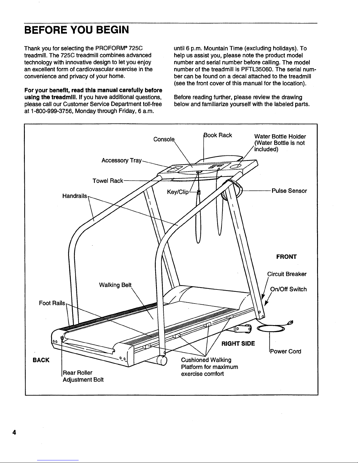
Before reading further, please review the drawing
below and familiarize yourself with the labeled parts.
Console
Water Bottle Holder
(Water Bottle is not
Towel Rack
Handrails
Pulse Sensor
FRONT
Foot Rails
Walking Belt
Circuit Breaker
On/Off Switch
BACK
Rear Roller
Adjustment Bolt
RIGHT SIDE
Cushioned Walking
Platformfor maximum
exercise comfort
Power Cord
4
Page 5
ASSEMBLY
Assembly requires two people, Set the treadmill in a cleared area and remove the packing materials. Do not
dispose of the packing materials until assembly is completed. For help identifying the small parts used in
assembly, refer to the HARDWARE IDENTIFICATION CHART inthis manual. Assembly requires two adjustable
wrenches _ and a phillips screwdriver _ (not included).
o
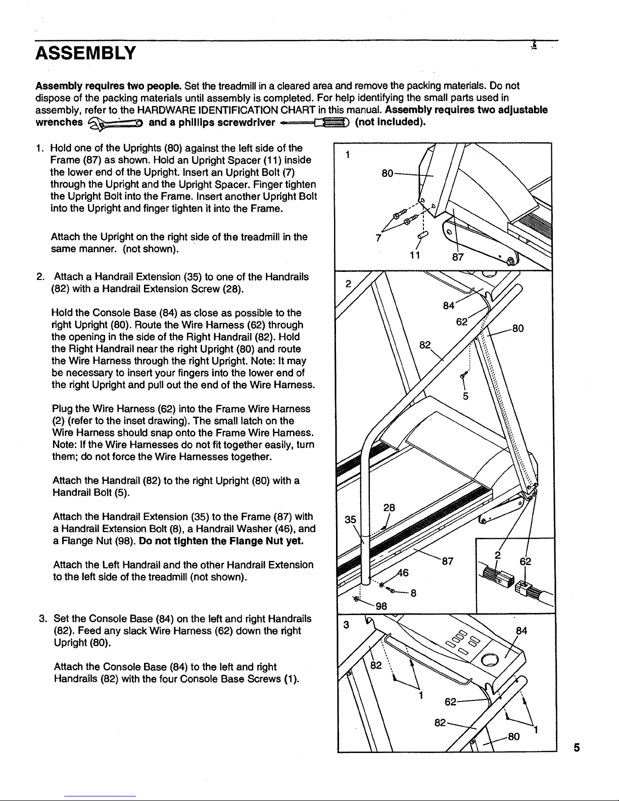
Hold one of the Uprights (80) against the left side of the
Frame (87) as shown. Hold an Upright Spacer (11 ) inside
the lower end of the Upright. Insert an Upright Bolt (7)
through the Upright and the Upright Spacer. Finger tighten
the Upright Bolt into the Frame. Insert another Upright Bolt
into the Upright and finger tighten it into the Frame.
Attach the Upright on the right side of the treadmill in the
same manner. (not shown).
°
Attach a Handrail Extension (35) to one of the Handrails
(82) with a Handrail Extension Screw (28).
Hold the Console Base (84) as close as possible to the
right Upright (80). Route the Wire Harness (62) through
the opening in the side of the Right Handrail (82). Hold
the Right Handrail near the right Upright (80) and route
the Wire Harness through the right Upright. Note: It may
be necessary to insert your fingers into the lower end of
the right Upright and pull out the end of the Wire Harness.
Plug the Wire Harness (62) into the Frame Wire Harness
(2) (refer to the inset drawing). The small latch on the
Wire Harness should snap onto the Frame Wire Harness.
Note: If the Wire Harnesses do not fit together easily, turn
them; do not force the Wire Harnesses together.
Attach the Handrail (82) to the right Upright (80) with a
Handrail Bolt (5).
Attach the Handrail Extension (35) to the Frame (87) with
a Handrail Extension Bolt (8), a Handrail Washer (46), and
a Flange Nut (98). Do not tighten the Flange Nut yet.
Attach the Left Handrail and the other Handrail Extension
to the left side of the treadmill (not shown).
3. Set the Console Base (84) on the left and right Handrails
(82). Feed any slack Wire Harness (62) down the right
Upright (80).
Attach the Console Base (84) to the left and right
Handrails (82) withthe four Console Base Screws (1).
87
2
87
84
5
Page 6
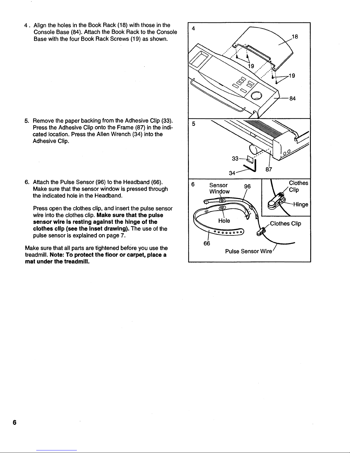
4. Align the holes in the Book Rack (18) with those in the
Console Base (84). Attach the Book Rack to the Console
Base with the four Book Rack Screws (19) as shown.
.
Remove the paper backing from the Adhesive Clip (33).
Press the Adhesive Clip onto the Frame (87) in the indi-
cated location. Press the Allen Wrench (34) into the
Adhesive Clip.
6. Attach the Pulse Sensor (96) to the Headband (66).
Make sure that the sensor window is pressed through
the indicated hole in the Headband.
Press open the clothes clip, and insert the pulse sensor
wire into the clothes clip. Make sure that the pulse
sensor wire Is resting against the hinge of the
clothes clip (see the Inset drawing). The use of the
pulse sensor is explained on page 7.
Make sure that all parts are tightened before you use the
treadmill. Note: To protect the floor or carpet, place a
mat under the treadmillo
4
Clip
66
Pulse Sensor Wire
6
Page 7
HOW TO USE THE PULSE SENSOR
The unique headband-style pulse sensor is specially
designed for greater accuracy, comfort, and durability.
To get the best performance from the pulse sen-
sor, please read the following instructions.
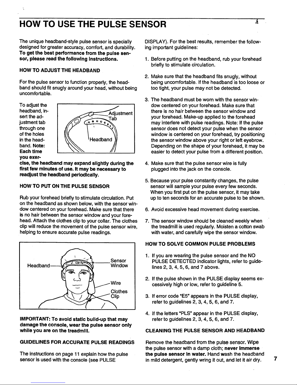
HOW TO ADJUST THE HEADBAND
For the pulse sensor to function properlY, the head-
band should fit snugly around your head, without being
uncomfortable.
To adjust the
headband, in-
sert the ad- Tab
justment tab
through one
ofthe holes
in the head-
band. Note:
Each time
you exer-
cise, the headband may expand slightly during the
first few minutes of use. It may be necessary to
readjust the headband periodically.
HOW TO PUT ON THE PULSE SENSOR
Rub your forehead briefly to stimulate circulation. Put
on the headband as shown below, with the sensor win-
dow centered on your forehead. Make sure that there
is no hair between the sensor window and your fore-
head. Attach the clothes clip to your collar. The clothes
clip will reduce the movement of the pulse sensor wire,
helping to ensure accurate pulse readings.
Sensor
Headband-__ Window
_j___lli_es
IMPORTANT: To avoid static build-up that may
damage the console, wear the pulse sensor only
while you are on the treadmill.
GUIDELINES FOR ACCURATE PULSE READINGS
The instructions on page 11 explain how the pulse
sensor is used with the console (see PULSE
DISPLAY). For the best results, remember the follow-
ing important guidelines:
1. Before putting on the headband, rub your forehead
briefly to stimulate circulation.
2. Make sure that the headband fits snugly, without
being uncomfortable. If the headband is too loose or
too tight, your pulse may not be detected.
. The headband must be worn with the sensor win-
dow centered on your forehead. Make sure that
there is no hair between the sensor window and
your forehead. Make-up applied to the forehead
may interfere with pulse readings. Note: If the pulse
sensor does not detect your pulse when the sensor
window is centered on your forehead, try positioning
the sensor window above your right or left eyebrow.
Depending on the shape of your forehead, it may be
easier to detect your pulse from a different position.
4. Make sure that the pulse sensor wire is fully
plugged into the jack on the console.
o
Because your pulse constantly changes, the pulse
sensor will sample your pulse every few seconds.
When you first put on the pulse sensor, it may take
up to ten seconds for an accurate pulse to be shown.
6. Avoid excessive head movement during exercise.
7. The sensor window should be cleaned weekly when
the treadmill is used regularly. Moisten a cotton swab
with water, and carefully wipe the sensor window.
HOW TO SOLVE COMMON PULSE PROBLEMS
1. If you are wearing the pulse sensor and the NO
PULSE DETECTED indicator lights, refer to guide-
lines 2, 3, 4, 5, 6, and 7 above.
2. If the pulse shown in the PULSE display seems ex-
cessively high or low, refer to guideline 5.
3. If error code "E5" appears in the PULSE display,
refer to.guidelines 2, 3, 4, 5, 6, and 7.
4° If the letters "PLS" appear in the PULSE display,
refer to guidelines 2, 3, 4, 5, 6, and 7.
CLEANING THE PULSE SENSOR AND HEADBAND
Remove the headband from the pulse sensor. Wipe
the pulse sensor with a damp cloth; never Immerse
the pulse sensor In water. Hand wash the headband
in mild detergent, gently wring itout, and let it air dry.
7
Page 8

OPERATION AND ADJUSTMENT
THE PERFORMANT LUBETM WALKING BELT
Your treadmill features a walking belt coated with
PERFORMANT LUBETM, a high-performance lubricant.
IMPORTANT: Never apply silicone spray or other
substances to the walking belt or the walking plat-
form. They will deteriorate the walking belt and
cause excessive wear.
HOW TO PLUG IN THE POWER CORD
electric shock. This product is equipped with a cord
having an equipment-grounding conductor and a
grounding plug. Plug the power cord Into a surge
protector, and plug the surge protector Into an ap-
propriate outlet that Is properly Installed and
grounded In accordance with all local codes and
ordinances.
This product is for use on a nominal 120-volt circuit,
and has a grounding plug that looks like the plug illus-
trated in drawing 1 below. A temporary adapter that
looks like the adapter illustrated in drawing 2 may be
used to connect the surge protector to a 2-pole recep-
tacle as shown in drawing 2 if a properly grounded out-
let is not available.
The temporary adapter should be used only untila
properly grounded outlet (drawing 1) can be installed
by a qualified electrician.
Your treadmill, like any other type of sophisticated
electronic equipment, can be seriously damaged by
sudden voltage changes in your home's power.
Voltage surges, spikes, and noise interference can re-
sultfrom weather conditions or from other appliances
being turned on or off.
To decrease the pos-
sibility of your tread-
mill being damaged,
always use a surge
protector (not In-
cluded) with your
treadmill.
Surge protectorsare
soldat most hardware
stores and department
stores. Use only a UL-
listed surge protector,
rated at 15 amps, with a
14-gauge cord offive
feet or less in length.
This product must be
grounded, if it should
malfunction or break
down, grounding pro-
vides a path of least re-
sistance for electric cur-
rent to reduce the riskof
The green-colored rigid ear, lug, or the like extending
from the adapter must be connected to a permanent
ground such as a properly grounded outlet box cover.
Whenever the adapter is used it must be held in place
by a metal screw. Some 2-pole receptacle outlet box
covers are not grounded. Contact a qualified elec-
trician to determine if the outlet box cover Is
grounded before using an adapter.
Treadmill
._,,//_._jj, Grounded Outlet Box
I g_. J !Grounding Pin
_" _unding Plug
_Grounded Outlet
Grounded Outlet Box
Adapter
ding Pin
Grounding Plug
_Ugcre w_
Surge Protector
8
Page 9

DIAGRAM OF THE CONSOLE
SPEED PROGRAMS
welol_rLo5 I _ z
30 25 20 15 10 5 m_ 0
...._"_=--_"_,T" ,° _o _, ,,__'--'i
J
Clip
INSERT KEY
SELECT PROGRAM MODE mr 0
3 CALORIES
SETWEIGHT _ \/WEIGHT/\ I J O
4 _;_'
s,,Ao.,[ v AO,A'I__.]k
WEAR _(sSENSOR PULSE
St"T MAX'SPEEO V MAX.SPO. /_ _0
7
PRESSS_RT _ START/PAUSE } I
Nom:_Jl,,e _
_, STOP V SPEED A
Key_
IE-,: 811
TIME TRAINING
ZONES
i ) Pe_ormar_'t5.5 ,..o..
DIS TANCE / INCLINE
Ma.a'tmum
) Fa_ 8wn
) F,ttBum
2m°2 I
Pulse Sensor Jack
Note: If there is a thin sheet of clear plas-
tic on the face of the console, remove it.
FEATURES OFTHECONSOLE
The treadmill console offers an impressive array of fea-
tures designed to make your workouts more effective
and enjoyable. When the console is in the manual mode,
the speed and inclineof the treadmill can be changed
with a touch of a button. As you exercise, five displays
will provide continuous exercise feedback. Seven preset
programs are also offered: two WEIGHT LOSS programs
and two INTERVAL programs automatically controlthe
speed of the treadmill as they guide you through effective
workouts; the special FAT BURN program provides in-
tensive fat-buming workouts; the AEROBIC program
helps you to achieve maximum cardiovascular benefits;
and the unique FITNESS TEST program measures your
relative fitness level.
To use the manual mode, followthe steps on pages 10
through 12. To use the WEIGHT LOSS or INTERVAL
programs, see pages 12 and 13. To use the FAT BURN
or AEROBIC program, see pages 14 and 15. To use the
FITNESS TEST program, see pages 15 and 16. Note:
The console can display speed and distance in.either
miles or kilometers (see SPEED DISPLAY on page 11).
For simplicity,all instructionsin this manual refer to miles.
Before beginning, make sure
that the on/off switch located
near the power cord is in the
"on" position. Plug in the power
cord (see page 8). Note: If the
key is in the console when the
"On"
Position
power cord isplugged in, the letters "PO" willflash inthe
SPEED display. If this occurs, remove the key.
9
Page 10

10
B Insert the key fully Into the console.
Stand on the foot rails
and insert the key.
Various displays and in-
dicators will light. Find
the clip attached to the
key and slide it onto the
waistband of your cloth-
ing.
B
Select the MANUAL mode.
When the key is in-
serted, the manual
mode will automatically _
be selected. The MAN- _ MODE
UAL CONTROL indica-
tor will light. Note: If a _HT /k "_
preset program has
been selected, press the MODE button repeatedly
to select the manual mode again.
Enter your weight, if desired.
Although it is not necessary to enter your weight and
age to use the manual mode, the CALORIES dis-
play will be more accurate if your weight and age
are entered. To enter your weight:
Press the
WEIGHT in-
crease or de-
crease button.
The letters
"LbS" will flash
in the CALO-
RIES display. Press one of the WEIGHT buttons
again. The current weight setting will then be
shown. Press the WEIGHT buttons again to enter
your weight. Each time one ofthe buttons is
pressed, the weight setting will change by 1
pound. If one of the buttons is held down, the
weight setting will change in increments of 5
pounds. After you have entered your weight, your
weight will be shown in the CALORIES display for
three seconds.
Enter your age, if desired.
To enter your age:
• Press the AGE increase or decrease button. The
letters =AGE" will flash in the PULSE display.
Press one of the AGE buttonsagain. The current
age setting willthen be shown. Press the AGE
buttons again to enter your age. Each time one of
the buttons is pressed, the age setting will change
by I year. If one of the buttons is held down, the
age setting wilt change in increments of 5 years.
After you have entered your age, your age will be
shown in the PULSE display for three seconds.
Note: Once you have entered your weight and age,
the numbers will be saved in the console's memory,
even if the power cord is unplugged.
Put on the pulse sensor, if desired.
For the PULSE dis-
play to show your
pulse, the pulse sen-
sor must be worn. To
put on the pulse sen-
sor, see HOW TO
USE THE PULSE SENSOR on page 7. Plug the
pulse sensor fully into the jack on the front of the
console.
B ress the SPEED Increase button to start the
walking belt.
The speed of
the walking
belt is con-
trolledwith
the SPEED
increase and
decrease but-
j t J
tons. Each time one of the buttons is pressed, the
speed will change by 0.1 mile per hour (mph), The
buttons can be held down to change the speed
quickly.The speed range is0.5 mph to 10 mph.
Press the SPEED increase button until the walking
belt begins to move at slowspeed. Hold the
handrails and carefully begin walking. Change the
speed of the walking belt as desired by pressing the
SPEED buttons. Note: The walking beltcan also be
started by pressing the START/PAUSE button. The
walking belt will begin to move at 0.5 mph. The
speed can then be adjusted with the SPEED buttons.
To stop the walking belt, press the START/PAUSE
button. All displays will pause and the TIME display
will begin to flash. To restart the walking belt, press
the SPEED buttons or the START/PAUSE button as
described above. Note: The walking belt can also be
stopped by pressing the STOP button. To restart the
walking belt, press the SPEED buttons or the
START/PAUSE button as described above.
Note: When the SPEED buttons are pressed, the
SPEED display will show the selected speed setting
for seven seconds. The display will then show the
actual speed ofthe walking belt.
Page 11

B
Change the incline of the treadmill, if desired.
The incline of the tread- I I
mill is controlled with the
INCLINE increase and I I
decrease buttons. Each V INCLINE _/_
time one of the: buttons
is pressed, the incline
will change by 0.5%.
The buttons can be held down to change the incline
quickly. The incline setting is shown in the DIS-
TANCE/INCLINE display. The incline range is 1.5%
to 10%. Note: After the INCLINE buttons are
pressed, it may take a few seconds for the treadmill
to reach the selected incline setting.
_ ollow your progress with the five displays and
the TRAINING ZONE monitor.
CALORIES display
This display shows
both the total calories
and the number of fat
calories that you have
burned. (See BURN-
ING FAT on page 19
for an explanation of fat calories). Every seven
seconds, the display will change from one number
to the other. The FAT indicator beside the display
will light when the number of fat calories is shown.
Note: This display also shows the current weight
setting when the walking belt is stopped and the
WEIGHT buttons are pressed.
PULSE display
For this display to op-
erate, the pulse sen-
sor must be worn (see
HOW TO USE THE
PULSE SENSOR on
page 7). After a few
seconds, the head-
o_ ° CALORIES J
PULSE
shaped indicator beside the PULSE display will
flash each time your head beats, the NOT DE-
TECTED indicator will darken, and your pulse will
be shown. Note: Because your pulse constantly
changes, the pulse sensor willsample your pulse
every few seconds. It may take up to ten seconds
before an accurate pulse is shown. If your pulse is
not shown, see GUIDELINES FOR ACCURATE
PULSE READINGS on page 7.
Note: This display also shows the current age set-
ting when the walking belt is stopped and the AGE
buttons are pressed.
SPEED display
This display shows
the current speed of
the walking belt.
When the SPEED
buttons are pressed,
the display will show
SPEED /_
the selected speed setting for seven seconds. The
display will then show the actual speed of the
walking belt.
Note: The speed can be displayed in either miles
per hour (mph) or kilometers per hour (kph). The
indicators beside the SPEED display will light to
show which unit of measurement is selected. To
change the unit of measurement, first hold down
the STOP button while inserting the key into the
console. An "E" (for English system [miles]) or "M"
(for Metric system [kilometers]) will appear in the
SPEED display. Press the SPEED increase button
to change the unit of measurement. Remove and
then reinsed the key.
TIME display
This display shows
the total time that the
walking belt has
been moving.
,,_,::_','-lJ
Fr_,_ _ TIME
Note: When any pro-
gram except the FITNESS TEST program is se-
lected, the TIME display will showthe time re-
maining in the program.
DISTANCE/INCLINE display
This display shows
both the distance
that the walking belt
has moved and the
current incline of the
treadmill. Every
seven seconds, the
display will change
from one number to the other. When the INCLINE
buttons are pressed, the display will change to
show the selected incline setting.
[,-'.3:-121}
DIST. / INCLINE
Note: If the MPH indicator beside the SPEED dis-
play is lit, the distance will be displayed in miles. If
the KPH indicator is lit, the distance will be dis-
played in kilometers.
11
Page 12

• Training Zone Monitor
The training zone monitor
measures the approximate
intensity of your exercise.
The monitor's five indicators
are described below:
WARM UP & COOL
DOWN--Each workout
should begin with a warm-
up period and end with a
j ;"o_,,'_"_"_
cool-down period. (See WORKOUT GUIDE-
LINES on page 19.) The WARM-UP & COOL-
DOWN indicator will light when your workout in-
tensity is ideal for warming up or cooling down.
FAT BURN and MAXIMUM FAT BURN--To
burn fat effectively, you must exercise at a rela-
tively low intensity level for a sustained period of
time. (See BURNING FAT on page 19.) If you
are exercising at the proper intensity level for
burning fat, the FAT BURN or MAXIMUM FAT
BURN indicator will light.
AEROBIC--If your goal is to strengthen your
cardiovascular system, your exercise must be
"aerobic." (See AEROBIC EXERCISE on page
19.) Ifyou are exercising at the proper intensity
level for aerobic exercise, the AEROBIC indica-
tor will light.
PERFORMANCE--If your goal is high perfor-
mance athletic conditioning, you will need to ex-
ercise at a high intensity level. If you are exercis-
ing at the proper intensity level, the PERFOR-
MANCE indicator will light.
When you are finished exercising, stop the walk-
Ing belt and remove the key.
Step ontothe foot rails and stop the walking belt.
Lower the treadmill tothe lowest incline level.
Remove the key from the console and store the key
in a secure place. In addition, move the on/off switch
to the "off" position.(See the drawing near the bot-
tom of page 9.)
The WEIGHT LOSS programs and the INTERVAL
programs automatically controlthe speed of the walking
belt as they guide you through effective workouts. The
WEIGHT LOSS programs focus on helping you to lose
unwanted pounds; the INTERVAL programs are
designedto buildstamina.The WEIGHT LOSS programs
and the INTERVAL 1 program are 20-minute programs;
the INTERVAL 2 program is a 30-minute program. The
graphs on the leftside of the console show how the
speed will change during each program. During the
WEIGHT LOSS 1 program, for example, the speed will
gradually increase during the first 10 minutes, and then
gradually decrease duringthe last 10 minutes. Each
program begins with a 2-minute warm-up period, and
ends with a 2-minute cool-down period.
Follow the steps below to use one of these programs.
B ake sure that the key is fully Inserted Into the
console.
Stand on the foot rails
and insert the key.
Various displays and
indicators will light.
Find the clip attached
to the key, and slide it
onto your waistband.
Select the WEIGHT LOSS 1, WEIGHT LOSS 2,
INTERVAL 1, or INTERVAL 2 program.
When the key is inserted,
the MANUAL CONTROL
indicator will light. To select
the WEIGHT LOSS 1 pro-
gram, press the MODE but-
ton. The WEIGHT LOSS 1
indicator will light. To select
one of the other programs,
press the MODE button re-
___ MODE ]
-_ _/ AGE /_ _
peatedly until the WEIGHT LOSS 2, INTERVAL 1,
or INTERVAL 2 indicatorlights. Note: If the walking
belt is moving, it will slow to a stop.
Enter your weight, If desired,
12
When a WEIGHT LOSS or INTERVAL program is
selected, the letters "LbS" willflash in the CALO-
RIES displayfor seven seconds; the current weight
settingwill then be shown. Although it is not neces-
sary to enter your weight and age to use one of
these programs, the CALORIES display will be more
accurate if your weight and age are entered. If you
want to enter your weight, see step 3 on page 10.
Page 13

O
Enter your age, if desired.
After you have completed step 3, the letters "AGE"
willflash in the PULSE display for seven seconds;
the current age setting will then be shown. If you
want to enter your age, see step 4 on page 10.
Put on the pulse sensor, if desired.
For the PULSE display
to show your pulse, the
pulse sensor must be
worn. To put on the
pulse sensor, see HOW
TO USE THE PULSE
SENSOR on page 7.
Plug the pulse sensor fully into the jack on the front
of the console.
Set a maximum speed for the program.
After you have
completed step
4, a number will
appear in the
SPEED display
and flash for
seven secends.
START/PAUSE _'_0 -- --
This number shows the maximum speedthat the
walking belt will move during the program. The max-
imum speed setting can be from 3.0 mph to 8.5
mph. If you want to change the maximum speed set-
ting, press the MAX. SPD. increase or decrease but-
ton. Note: The maximum speed setting will change
by 0.3 mph each time one of the MAX. SPD. buttons
is pressed, until itreaches 4.5 mph; the maximum
speed setting will then change by 0.5 mph each time
one of the buttons is pressed untilit reaches 8.5 mph.
If the maximum speed setting is between 3.0 mph
and 5.0 mph, the walking belt willmove at 1.5 mph
during the first 2 minutes and the last 2 minutes of
the program (the warm-up and cool-down periods).
The speed range during the rest of the program will
be 1.5 mph. For example, ifthe maximum speed
setting is 5.0 mph, the speed range will be 3.5 mph
to 5.0 mph (a difference of 1.5 mph).
If the maximum speed setting is between 5.5 mph
and 8.5 mph, the walking belt will move at 3.0 mph
during the first 2 minutes and the last 2 minutes of
the program. The speed range during the rest of the
program will be 2.0 mph.
B ress the START/PAUSE button to start the_pro-
gram.
When the
START/PAUSE
button is
pressed, the
TIME display
will begin
counting down
STOP J [ V sP_oA
from 20 minutes (or 30 minutes if the INTERVAL 2
program is selected). After a moment, the walking
belt will begin to move. Hold the handrails and care-
fully begin walking.
As the program progresses, the speed of the walk-
ing belt willchange periodically as shown by the
graphs on the left side of the console. The program
will continue until the time shown in the TIME dis-
play reaches zero. The walking belt willthen slow to
a stop and the program will be completed.
Note: The SPEED buttons willnot respondwhile a
WEIGHT LOSS or INTERVAL program is selected. If
the program istoo easy or too challenging, press the
MAX. SPD. buttonsto set a new maximum speed.
The new maximum speed setting will be shown in the
SPEED display for 3 seconds. To stop the program
temporarily, press the START/PAUSE button. The
TIME displaywill begin to flash. To restart the pro-
gram, press the START/PAUSE buttonagain. The
program willresume and the walking belt willretum to
the latest speed setting. To terminate the program be-
fore the program iscompleted, press the STOP but-
ton.
Change the incline of the treadmill, if desired.
When a WEIGHT LOSS or INTERVAL program is
selected, the incline of the treadmill can be changed
with the INCLINE buttons. See step 7 on page 11.
_1 ollow your progress with the five displays and
the TRAINING ZONE monltor.
See TRAINING ZONE MONITOR on page 12.
When you are finished exercising, stop the
walking belt and remove the key.
Step onto the foot rails, stop the walking belt, and re-
move the key from the console.Store the key ina se-
cure place. In addition, move the on/off switch to the
"off" position.(See the drawing near the bottom of
page 9.)
13
Page 14

The FAT BURN and AEROBIC programs automatically
control the speed and incline of the treadmill to keep
your pulse within a predetermined range during your
workouts. Both programs are 30-minute programs. The
graphs on the left side of the console show how your
pulse will change during each program. Each program
begins with a warm-up period, and ends with a cool-
down period.
To use one of these programs, follow the steps below.
Make sure that the key is fully Inserted Into the
console.
Stand on the foot rails
and insert the key.
Various displays and in-
dicators will light. Find
the clipattached to the
key,and slide it onto the
waistband of your cloth-
ing.
Select the FAT BURN or AEROBIC program.
Press the MODE button
repeatedly until the FAT
BURN or AEROBIC indi-
cator lights. Note: If the
walking belt is moving, it
will slow to a stop.
lg
Enter your weight.
When the FAT BURN or AEROBIC program is se-
lected, the letters =LbS" will flash in the CALORIES
display. You must enter your weight and age before
either of these programs can be started. To enter
yourweight, see step 3 on page 10. If you have al-
ready entered your weight, you must press one of
the WEIGHT buttons to verify the weight setting.
E!
Enter your age.
After you have completed step 3, the letters =AGE"
will flash in the PULSE display. To enter your age,
see step 4 on page 10. If you have already entered
your age, you must press one of the AGE buttons to
verify the age setting.
m
Put on the pulse sensor.
The pulse sensor must
be wom when the FAT
BURN or AEROBIC
program is used. To put
on the pulse sensor,
see HOW TO USE THE
PULSE SENSOR on page 7. Plug the pulse sensor
fully into the jack on the front of the console. Note:
The FAT BURN and AEROBIC programs can be
started without your pulse being detected; however,
the programs wilt automatically stop if your pulse is
not detected 2 minutes after the programs are
started.
r_ Press the START/PAUSE button to start the pro-
gram.
When the START/
PAUSE button is
pressed, the TIME dis-
play will begin count-
ing down from 30 min-
utes. After a moment,
the walking belt will
STOP
begin to move. Hold the handrails and carefully
begin walking.
As the program progresses, the speed and incline of
the treadmill will change periodically to keep your
pulse within a predetermined range, shown by the
graphs on the left side of the console. When the
time shown in the TIME display reaches zero, the
walking belt will slow to a stop and the program will
be completed.
Note: If your pulse is
not detected during
the program, the NOT
DETECTED indicator
will light and the letters
"PLS" willflash in the
PULSE display. (See
........ i
lI0
PULSE
GUIDELINES FOR ACCURATE PULSE READ-
INGS on page 7.) If your pulse is not detected at the
end of any 2-minute period during the program (after
2 minutes, after 4 minutes, after 6 minutes, etc,), the
program will automatically stop.
Note: Minor adjustments can be made to the speed
or incline of the treadmill during the program by
pressing the SPEED or INCLINE buttons. However,
ifyou increase the speed, the incline will automati-
cally decrease; if you decrease the speed, the in-
cline will automatically increase. If you increase the
14
Page 15

incline, the speed will automatically decrease; if you
decrease the incline, the speed will automatically
increase. The console will always attempt to keep
your pulse near a predetermined setting. When the
incline reaches the highest setting, the speed can-
not be decreased any further. When the incline
reaches the lowest setting, the speed cannot be
increased any further.
Note: To stop the program temporarily, press the
START/PAUSE button. The TIME display will begin
to flash. To restart the program, press the
START/PAUSE button again. The program will
resume and the walking belt will retum to the latest
speed setting. To terminate the program before the
program is completed, press the STOP button.
Follow your progress with the five displays and
the TRAINING ZONE monitor.
See step 8 on pages 11 and 12.
1_1 hen you are finished exercising, stop the walk-
ing belt and remove the key.
Step ontothe foot mils, stop the walking belt, and re-
move the key from the console. Store the key in a
secure place. In addition, move the on/off switch to
the "off" position. (See the drawing near the bottom
of page 9.)
To use the FITNESS TEST program, follow the steeps
below.
B ake sure that the key is fully Inserted into the
console.
Stand on the foot rails
and insert the key.
Various displays and
indicators will light.
Find the clip attached
to the key, and slide it
onto the waistband of
your clothing.
B
Select the FITNESS TEST program.
To select the FIT-
NESS TEST pro-
gram, press the
MODE button repeat-
edly until the FIT-
NESS TEST indicator
lights. Note: If the
walking belt is moving, it will slow to a stop.
!_1 Enter your weight.
When the FITNESS TEST program is selected, the
letters "LbS" will flash in the CALORIES display.
You must enter your weight and age before this pro-
gram can be started. To enter your weight, see step
3 on page 10. If you have already entered your
weight, you must press one of the WEIGHT buttons
to verify the weight setting.
Enter your age.
After you have completed step 3, the letters =AGE"
will flash in the PULSE display. To enter your age,
see step 4 on page 10. If you have already entered
your age, you must press one of the AGE buttons to
verify the age setting.
Put on the pulse sensor.
The FITNESS TEST program is designed to measure
your relative fitness level. For the best results, the
FITNESS TEST should be taken at a time when your
energy level is high. The FITNESS TEST should not be
taken if you have already exercised during the day.
The FITNESS TEST program consists of seven 4-
minute periods, and is followed by a 2-minute cool-
down period. The speed and/or incline of the treadmill
will automatically increase at the beginning of each 4-
minute period.
The pulse sensor
must be worn when
the FITNESS TEST
program is used. To
put on the pulse sen-
sor, see HOW TO
USE THE PULSE
SENSOR on page 7. Plug the pulse sensor fully into
the jack on the front of the console. Note: The FIT-
NESS TEST program can be started without your
pulse being detected; however, the program will au-
tomatically stop if your pulse is not detected 4 min-
utes after the program is started.
15
Page 16

r,_ Press the START/PAUSE button to start the pro-
gram.
nte
PAUSE button is _ MAXSPO/k
pressed, the TIME dis-
play will begin counting START/PAUSE
up. The CALORIES dis-
play will show "L 1" STOP
(level 1), indicating that
the first4-minute period of the FITNESS TEST pro-
gram has begun. The incline of the treadmill wi!l au-
tomatically adjust to 3.0%, and the walking belt will
begin to move at 1.5 mph. Hold the handrails and
carefully begin walking.
When the TIME display reaches 4 minutes,the
CALORIES display will show "L 2," indicatingthat
the second 4-minute period has begun. The incline
will increase to 4%, and the speed will increase to
2.5 mph. At the beginning of each 4-minute period,
the speed and/or incline of the treadmill will auto-
matically increase. The FITNESS TEST will continue
in this manner until your pulse reaches 70% of your
maximum heart rate, and the current 4-minute period
is completed. The FITNESS TEST will then be com-
pleted, regardless of how many periods remain.
When the FITNESS TEST is completed, the letter
"C" will be shown in the CALORIES display, indicat-
ing that the cool-down period has begun. The TIME
display will count down from 2 minutes. When the
cool-down period is completed, the walking belt will
slow to a stop. Note: During the last ten seconds
of the cool-down period, the treadmill will auto-
matlcally adjust to the lowest Incline level. Keep
your feet and objects from beneath the treadmill.
After the program is completed, your fitness level
will be shown in the TIME display. There are ten fit-
ness levels--fitness
level 10 (FL:10) is the
highest. Remember, _ L'-'-_ 3/--._ lJ
the FITNESS TEST is
intended only to indi-
cate your relative fit- TIME
heSSlevel.
after 8 minutes, etc.), the walking belt will slow to a
stop, the FITNESS TEST will end, and the TIME dis-
play will show a fitness level of 0 (FL:00). (See
GUIDELINES FOR ACCURATE PULSE READ-
INGS on page 7.) The FITNESS TEST program
cannot be stopped temporarily and then restarted.
However, the program can be stopped at any time
by pressing the STOP button. The TIME display will
then show an estimated fitness level. If the STOP
button is pressed a second time, the MANUAL
mode will be selected.
B hen you are finished exercising, stop the walk-
Ing belt and remove the key.
Step ontothe foot rails, stop the walking belt, and re-
move the key from the console. Store the key in a
secure place. In addition, move the on/oft switchto
the "off" position.(See the drawing near the bottom
of page 9.)
HOW TO SELECT THE INFORMATION MODE
The console features an information mode that keeps
track of the total time and distance accumulated on the
treadmill.
To access the information mode, hold down the STOP
buttonwhile insertingthe key into the console. The
TIME display willshow the total time accumulated on
the treadmill, in hours. The DISTANCE/INCLINE display
will show the total distance, in miles (if the total distance
exceeds 999 miles, the thousands and ten thousands
digits will be shown in the PULSE display). Note: The
SPEED display will show an "E"(for English system
[miles]) or "M" (for Metric system [kilometers]) (see
SPEED DISPLAY on page 11).
To exit the information mode, remove the key.
16
Note: The SPEED and INCLINE buttons will not re-
spond while the FITNESS TEST program isselected.
Ifyour pulse is not de-
tected during the pro-
gram, the NOT DE-
TECTED indicator will
light and the letters
"PLS" will flash in the
PULSE display. If your
pulse is not detected
during the last thirty
.__ _tL.tJrltco j
//E/
PULSE
I f
.-- -- II
seconds of any 4-minute period (after 4 minutes,
Page 17

TROUBLE-SHOOTING
Most treadmill problems can be solved by following the steps below. Find the symptom that applies, and
follow the steps listed,
If further assistance Is needed, please call our Customer Service Department toil-free at 1-800-999-3756,
Monday through Friday, 6 a.m. until 6 p.m. Mountain Time (excluding holidays),
1. SYMPTOM: THE POWER DOES NOT TURN ON
a. Make sure that the power cord is plugged into a surge protector, and that the surge protector is plugged into
a properly grounded outlet. (See HOW TO PLUG IN THE POWER CORD on page 8.) Use only a UL-listed
surge protector, rated at 15 amps, with a 14-gauge cord of five feet or less in length.
b. After the power cord has been plugged in, make sure that the key is fully inserted intothe console. (See step
1 on page 10.)
C. Check the circuit breaker located on the treadmill near the
power cord. If the switch protrudes as shown, the circuit
breaker has tripped. To reset the circuit breaker, wait for five
minutes and then press the switch back in.
d. Check the on/off switch located at the front of the treadmill
near the power cord. The switch must be in the "on" position.
2. SYMPTOM: THE POWER TURNS OFF DURING USE
c
Tripped
Reset
a. Check the circuit breaker located on the treadmill frame near the power cord (see 1. c. above). If the circuit
breaker has tripped, wait for five minutes and then press the switch back in.
b. Make sure that the power cord is plugged in.
c. Remove the key from the console. Reinsert the key fully intothe console. (See step 1 on page 10.)
d. Check to make sure that the on/off switch isin the "on" position. (See 1. d. above.)
e. If the treadmill stillwill not run, please call our Customer Service Department, toll-free.
3. SYMPTOM: THE WALKING BELT SLOWS WHEN WALKED ON
a. Use only a UL-listed surge protector, rated at 15 amps, with a 14-gauge cord of five feet or less in length.
b. If the walking belt stillslows when walked on, please call our Customer Service Department, toll-free.
4. SYMPTOM: AN ERROR CODE ("E2," "E3, .... E4," OR "E5") APPEARS ON THE CONSOLE
a.
Error code "E2" may appear in the SPEED display if the SPEED increase or START/PAUSE button is
pressed and no movement of the walking belt is detected within seven seconds. Remove the key, wait for
ten seconds, and then reinsert it. Make sure that you stand on the foot rails of the treadmill each time you
start the walking belt. If the error code appears again, call our toll-free Customer Service Department. Do not
operate the treadmill untilthe problem is corrected.
b°
Error code "E3" may appear in the SPEED display if the speed of the walking belt surges above the se-
lected speed setting. Remove the key, wait for ten seconds, and then reinsert it. If the error code appears
again, call our toll-free Customer Service Department. Do not operate the treadmill until the problem is cor-
rected.
17
Page 18

c. Error code "E4" may appear in the SPEED display if the walking belt is moving at a slow speed, and there is
excessive stresson the motor. Remove the key, wait for ten seconds, and then reinsert it. Ifyou weigh over
200 pounds, itmay be helpful to increase the incline of the treadmill. If the error code appears again, call our
toU-freeCustomer Service Department. Do not operate the treadmill untilthe problem is corrected.
d. Error code "E5" may appear in the PULSE display if a pulse error occurs. See HOW TO USE THE PULSE
SENSOR on page 7, and PULSE DISPLAY on page 11.
5. SYMPTOM: THE PULSE SENSOR DOES NOT FUNCTION PROPERLY
a. See HOW TO USE THE PULSE SENSOR on page 7, and PULSE DISPLAY on page 11.
6. SYMPTOM: THE WALKING BELT IS OFF-CENTER WHEN WALKED ON
a. Ifthe walking belt has shifted to the left, first remove the key and
UNPLUG THE POWER CORD. Using the allen wrench, turn
the left rear roller adjustment bolt clockwise 1/4 of a tum. Plug in
the power cord, insert the key and run the treadmill for a few
minutes. Repeat until the walking belt is centered.
b. If the walking belt has shifted to the right,first remove the key
and UNPLUG THE POWER CORD. Using the allen wrench, turn
the left rear roller adjustment bolt counterclockwise 1/4 of a turn.
Plug in the power cord, insert the key and run the treadmill for a
few minutes. Repeat until the walking belt is centered.
18
CONDITIONING GUIDELINES
The following guidelines will help you to plan your exer-
cise program. Remember--these are general guide-
lines. For more detailed information about exercise, ob-
tain a reputable book or consult your physician.
EXERCISE INTENSITY
Whether you want to burn fat, strengthen your cardio-
vascular system, or increase your athletic performance,
you can tailor your exercise to your specific goals. The
key to achieving the desired results isto exercise with
the proper intensity.
Page 19

Burning Fat
To burn fat effectively, you must exercise at a relatively
low intensity level for a sustained period of time. During
the first few minutes of exercise, your body uses easily
accessible carbohydrate calories for energy. Only after
the first few minutes of exercise does your body begin
to use stored fat calories for energy. If your goal is to
burn fat, adjust the speed and incline of the treadmill
untilthe FAT BURN indicator is lit. (See TRAINING
ZONE MONITOR on page 12.)
Aeroblc Exerclse
If your goal isto strengthen your cardiovascular sys-
tem, your exercise must be "aerobic." Aerobic exercise
is activitythat requires large amounts of oxygen for
prolonged periods of time. This increases the demand
on the heart to pump blood to the muscles, and on the
lungs to oxygenate the blood. The proper intensity level
for aerobic exercise can be found by using your pulse
as a guide. As you exercise, your pulse should be kept
at a level between 70% and 85% of your maximum
possible heart rate. This is known as your training
zone. You can find your training zone inthe table
below. Training zones are listed according to age and
physical condition.
Training Zone(Beats/Min.)
Age Unconditioned Conditioned
20 138-167 133-162
25 136-166 132-160
30 135-164 130-158
35 134-162 129-156
40 132-161 127-155
45 131-159 125-153
50 129-156 124-150
55 127-155 122-149
60 126-153 121-147
65 125-151 119-145
70 123-150 118-144
75 122-147 117-142
80 120-146 115-140
85 118-144 114-139
You can measure your pulse using the pulse sense.
Exercise for about four minutes, and then measure
your pulse immediately. If your pulse is too high or too
low, adjust the intensity of your exemise. It may also be
helpful to adjust the speed and incline of the treadmill
until the AEROBIC indicator is lit. (See TRAINING
ZONE MONITOR on page 12.)
Performance Training
If your goal is high performance athletic conditioning,
adjust the speed and incline of the treadmill untilthe
PERFORMANCE indicator is lit. (See TRAINING
ZONE MONITOR on page 12.)
WORKOUT GUIDELINES
Each workout should include three parts: (1) a warm-
up, (2) training zone exercise, and (3) a cool-down.
Warm-up
Warming up prepares the body for exercise by increas-
ing circulation, delivering more oxygen to the muscles
and raising the body temperature. Begin each workout
with 5 to 10 minutes of stretching and light exercise to
warm up.
Training Zone Exercise
After warming up, increase the intensity of your exer-
cise until your pulse is in your training zone for 20 to 60
minutes. (During the first few weeks of your exercise
program, do not keep your pulse in your training zone
for longer than 20 minutes.) Breathe regularly and
deeply as you exercise--never hold your breath.
Cool-down
Finish each workout with 5 to 10 minutes of stretching
to cool down. This will increase the flexibility of your
muscles and will help to prevent post-exercise prob-
lems.
Exercise Frequency
To maintain or improve your condition, complete three
workouts each week, with at least one day of rest
between workouts. After a few months, you ma.y com-
plete up to five workouts each week if desired.
The key to success is to make exercise a regular and
enjoyable part of your everyday life.
During the first few months of your exercise program,
keep your pulse near the low end of your training zone
as you exercise. After a few months of regular exer-
cise, your pulse can be gradually increased until it is
near the middle of your training zone as you exercise.
19
Page 20

Remove this HARDWARE IDENTIFICATION CHART,
EXPLODED DRAWING and PART LIST from the manual.
Save this page for future reference.
HARDWARE IDENTIFICATION CHART
The chart below is provided to help you identify the small parts used in assembly. The number in parenthesis
below each part refers to the key number of the part. The second number refers to the quantity used in assembly.
IMPORTANT: Some small parts have been pre-attached for shipping purposes, if a part is not found in the
part bag, check to see if it has been pre-attached.
Handrail Washer (46)-2
Flange Nut (98)-2
Handrail Bolt (5)-2
Handrail Extension
Screw (28)-2
Upright Spacer (11)-2
__1 Upright Bolt (7)-4
Handrail Extension Bolt (8)-2
Console Base
Screw (1)-4
Book Rack Screw (19)-4
Page 21

EXPLODEDDRAWING--ModelNo.PFTL35060
18
R0297A
25
t9
l
74
52
53
55
59
,12
9 5O
72
102
36
44
27
85
42
_40 49
-_o'°27
11
Page 22

PART LIST---Model No. PFTL35060
R0297A
Key No. Qty. Description
1 4 Console Base Screw
2 1 Frame Wire Harness
3 14 Console Screw
4 2 Nylon Washer
5 5 Handrail Bolt/incline Bolt/Motor Bolt
6 2 Push Nut
7 4 Upright Bolt
8 2 Handrail Extension Bolt
9 6 Cage Nut
10 2 Wheel Bolt
11 2 Upright Spacer
12 7 Nut
13 2 Incline Motor Bolt
14 4 Endcap Bolt
15 1 Short Adjustment Bolt
16 1 Long Adjustment Bolt
17 1 Towel Rack
18 1 Book Rack
19 4 Book Rack Screw
20 5 Hood Anchor Screw
21 5 Hood Anchor
22 1 Tie Holder
23 1 Motor Tension Washer
24 1 Motor Tension Star Washer
25 1 Motor Tension Nut
26 1 Motor Pivot Bolt
27 25 Screw
28 2 Handrail Extension Screw
29 16 Belly Pan Screw/Hood Screw
30 8 Platform Screw
31 4 8" Wire Tie
32 2 4" Wire Tie
33 1 Adhesive Clip
34 1 Allen Wrench
35 2 Handrail Extension
36 1 Power Supply with Clips
37 1 Choke
38 1 Switch Bracket
39 1 Circuit Breaker
40 1 On/Off Switch
41 1 Controller
42 1 Power Cord
43 1 Grommet
44 1 Electronics Bracket
45 1 Incline Disk
46 2 Handrail Washer
47 1 Releasable Wire Tie
48 1 Front Roller Ground Wire
49 1 Motor-Controller Wire
50 2 Frame Endcaps
51 2 Adjustment Washer
52 1 Roller Tension Nut
53 1 Spring Sleeve
54 1 Tension Spring
55 2 Endcap
56 2 Belt Guide
Key No. Qty. Description
57 2 Incline Wheel
58 1 Motor Belt
59 1 Motor
60 1 Pulley/Flywheel/Fan
61 1 Motor/Pulley/Flywheel/Fan
62 1 Wire Harness
63 1 Wire Harness Grommet
64 1 Key/Clip
65 1 Battery Cover
66 1 Headband w/Clip
67 2 Optic Switch Bolt
68 1 Console
69 1 Magnet
70 8 Isolator
71 1 Incline Motor
72 1 Front Roller
73 1 Rear Roller
74 1 Left Rail
75 1 Incline Leg
76 1 Endcap
77 1 Rear Roller Ground Wire
78 4 Plastic Standoff
79 1 Frame Plug
80 2 Upright
81 2 Optic Switch
82 2 Handrail
83 2 Flange Nut
84 1 Console Base
85 1 Hood
86 1 Belly Pan
87 1 Frame
88 1 Right Rail
89 1 Walking Platform
90 1 Walking Belt
91 2 Incline Spacer
92 1 Front Roller Adjustment Bolt
93 2 Foam Grip
94 2 Wheel Nut
95 1 Incline Stop Bracket
96 1 Pulse Sensor
97 2 Optic Sensor Wire
98 2 Flange Nut
99 1 Speed Optic Disk
100 1 Optic Switch Bracket
101 2 Small Star Washer
102 2 Small Nut
103 1 Bracket Nut
# 1 8" White Wire, Male/Female
# 1 8" White Wire, 2 Female
# 1 8" Blue Wire, 2 Female
# 1 4" Black Wire, 2 Female
# 1 8" Red Wire, Male/Female
# 1 User's Manual
* Includes all parts shown in the box
# These parts are not illustrated
Page 23

ORDERING REPLACEMENT PARTS
To order replacement parts, call our Customer Service Department toll-free at 1-800-999-3756, Monday through
Friday, 6 a.m. until 6 p.m. Mountain Time (excluding holidays). When ordering parts, please be prepared to give
the following information:
• The MODEL NUMBER OF THE PRODUCT (PFTL35060).
• The NAME OF THE PRODUCT (PROFORM ®725 C treadmill).
• The SERIAL NUMBER OF THE PRODUCT (see the front cover of this manual).
• The KEY NUMBER OF THE PART(S) (see the EXPLODED DRAWING and PART LIST attached to the center
of this manual).
• The DESCRIPTION OF THE PART(S) (see the EXPLODED DRAWING and PART LIST attached to the center
of this manual).
Ifpossible, place the treadmill near your telephone for easy reference when calling.
PROFORM is a registered trademark of ICON Health & Fitness, Inc.
LIMITED WARRANTY I
ICON Health & Fitness, Inc. (ICON), warrants this product to be free from defects in workmanship and
material, under normal use and service conditions, for a period of ninety (90) days from the date of pur-
chase. This warranty extends only to the original purchaser. ICON's obligation under this warranty is lim-
ited to replacing or repairing, at ICON's option, the product at one of its authorized service centers. All
products for which warranty claim is made must be received by ICON at one of its authorized service
centers with all freight and other transportation charges prepaid, accompanied by sufficient proof of pur-
chase. All returns must be pre-authorized by ICON. This warranty does not extend to any product or
damage to a product caused by or attributable to freight damage, abuse, misuse, improper or abnormal
usage or repairs not provided by an ICON authorized service center, to products used for commercial or
rental purposes, or to products used as store display models. No other warranty beyond that specifically
set forth above is authorized by ICON.
ICON is not responsible or liable for indirect, special or consequential damages arising out of or in con-
nection with the use or performance of the product or damages with respect to any economic loss, loss
of property, loss of revenues or profits, loss of enjoyment or use, costs of removal, installation or other
consequential damages of whatsoever nature. Some states do not allow the exclusion or limitation of in-
cidental or consequential damages. Accordingly, the above limitation may not apply to you.
The warranty extended hereunder is in lieu of any and all other warranties and any implied warranties of
merchantability or fitness for a particular purpose is limited in its scope and duration to the terms set
forth herein. Some states do not allow limitations on how long an implied warranty lasts. Accordingly,
the above limitation may not apply to you.
This warranty gives you specific legal rights. You may also have other rights which vary from state to state.
ICON HEALTH & FITNESS, INC., 1500 S. 1000 W., LOGAN, UT 84321-9813
Part No. 133506 G00384-C R0297A Printed in USA © 1997 ICON Health & Fitness, Inc.
 Loading...