


Pro-Flex,LLC
Flexible Gas Piping Systems
Pro-Flex ® & Flak Jacket TM CSST
Installation/Training Guide
Pro-Flex,LLC
501 South State Road 341
Hillsboro, IN 47949
Patented System: #5,845,946, #5,857,716, & 6,102,445 other patents pending
www. ProFlexCSST.com
Phone: 877-798-6291
Version 17.1
Fax: 765-6139
5/2017
PRO-FLEX® CSST
Training Guide and Installation Manual
TABLE OF CONTENTS
1.0 |
INTRODUCTION |
|
|
User Warnings, Limitations of Manual ................................................................................................ |
1-3 |
|
Applicable Codes & Standards ............................................................................................................... |
3 |
2.0DESCRIPTION OF SYSTEM AND COMPONENTS
|
System Components ........................................................................................................................... |
4-7 |
|
(Tubing, Fittings, Striker Plates, Pressure Regulators, |
|
|
Manifolds, Shut-off Valves, Other Components) |
|
3.0 |
SYSTEM CONFIGURATIONS |
|
|
System Configurations............................................................................................................................. |
8 |
|
Series Layout & Parallel Layout (low pressure)...................................................................................... |
9 |
|
Dual Pressure Layout .............................................................................................................................. |
9 |
|
Multiple Manifold Systems & Combination Steel/CSST System, Elevated Pressure System ............. |
9-10 |
|
Determine Pressure System ................................................................................................................. |
11 |
3.2 |
SIZING METHODS & EXAMPLES |
|
|
Low Pressure System (longest length method) (example #1).............................................................. |
12 |
|
Medium Pressure System (example #2) ............................................................................................... |
12 |
|
Elevated Dual Pressure System (example #3)....................................................................................... |
13 |
|
Combination Steel / CSST System......................................................................................................... |
14 |
4.0INSTALLATION PRACTICES / GUIDELINES
|
General Installation Guidelines........................................................................................................ |
16-17 |
|
Minimum Bend Radius ......................................................................................................................... |
17 |
|
Support ................................................................................................................................................. |
17 |
4.2 |
FITTING ASSEMBLY |
|
|
Assembly and Re-assembly Procedures ............................................................................................... |
18 |
|
Tubing Cutting / End Preparation.......................................................................................................... |
18 |
|
Minimum Tightening Torque ................................................................................................................ |
19 |
4.3 |
ROUTING |
|
|
Vertical Runs.......................................................................................................................................... |
20 |
|
Horizontal Runs..................................................................................................................................... |
20 |
|
Indoor / Outdoor Issues .................................................................................................................. |
20-21 |
|
Clearance Holes & Notching................................................................................................................. |
22 |
|
Concealed Locations for Fittings.......................................................................................................... |
23 |
4.4 |
PROTECTION |
|
|
Striker Plate Requirements............................................................................................................. |
24-25 |
|
Spiral Metal Hose Requirements ................................................................................................... |
24-25 |
|
Outdoor Installations...................................................................................................................... |
21, 26 |
|
Metal Wall Studs Installation .............................................................................................................. |
22 |
i
4.5 |
CONNECTIONS |
|
|
Meter Hook-ups .................................................................................................................................. |
26-27 |
|
Fixed Appliance..................................................................................................................................... |
28 |
|
Moveable Appliance /Termination Outlets............................................................................................ |
26 |
|
Pad Mounted Appliance........................................................................................................................ |
31 |
|
Gas Fireplace Installations .................................................................................................................... |
30 |
|
Fire Rated Construction through Plenums and Installations within a chase....................................... |
20 |
|
BBQ Gas Grill – Stationary.................................................................................................................... |
30 |
|
BBQ Gas Grill – Moveable .................................................................................................................... |
31 |
|
Gas Lamps............................................................................................................................................. |
31 |
|
CSST Buried Under Concrete Slab......................................................................................................... |
21 |
|
CSST Embedded in Concrete Slab ......................................................................................................... |
21 |
|
Supporting of Conduit Embedded in Reinforced Slab........................................................................... |
21 |
|
Short (2 to 6 ft) Outdoor Roof Mounted Installations.......................................................................... |
32 |
|
Long Length Outdoor Roof Mounted Installations............................................................................... |
32 |
|
Two Examples of Appliance Termination / Stub-out ............................................................................ |
32 |
|
Extending Existing CSST Tubing Run ..................................................................................................... |
23 |
4.7 |
MANIFOLD STATIONS |
|
|
Allowable Locations / Configurations ................................................................................................... |
33 |
4.8PRESSURE REGULATORS
|
Installation / Sizing Requirements ........................................................................................................ |
34 |
|
Vent Limiter Option............................................................................................................................... |
35 |
|
Vent Line and Sizing Requirements....................................................................................................... |
36 |
|
Adjustments .......................................................................................................................................... |
36 |
4.9 |
UNDERGROUND USAGE |
20, 21, 26 |
|
||
4.10 |
ELECTRICAL BONDING........................................................................................................................ |
37-38 |
5.0 |
INSPECTION / REPAIR / REPLACEMENT |
|
|
Inspection and Testing of Installed CSST............................................................................................... |
37 |
|
Pressure Testing and Inspection Procedures ........................................................................................ |
37 |
|
Appliance Connection Leakage Check Procedure ................................................................................. |
38 |
|
Repair / Replacement of Damaged CSSTTubing ............................................................................ |
39, 40 |
6.0SIZING TABLES (Natural Gas and LP Gas)
|
Natural Gas – Low Pressure to Medium Pressure |
.........................................................................41, 42 |
|
Natural Gas – Elevated Pressure ........................................................................................................... |
43 |
|
Natural Gas – 5 psig............................................................................................................................... |
44 |
|
Propane Gas .................................................................................................................................... |
45, 46 |
|
Iron Pipe Capacity Table ........................................................................................................................ |
47 |
|
Referenced Data ................................................................................................................................... |
48 |
7.0 |
TECHNICAL DATA SPECIFICATION SHEET.................................................................................................... |
49 |
8.0 |
CSST INSTALLATION CHECK LIST.................................................................................................................. |
50 |
9.0 |
DEFINITIONS OF TERMINOLOGY................................................................................................................. |
51 |
9.2 |
WARRANTY INFORMATION ........................................................................................................................ |
52 |
|
QUALIFIED INSTALLER CARD ........................................................................................ |
Inside Back Cover |
ii
1.0 Introduction
Pro-Flex® CSST and Flak JacketTM Arc-Resistant CSST must be installed by a qualified installer who meets the following criteria:
1.Installer must meet all qualifications required by the state and/or local administrative authority [AHJ] administering the provisions of the code where the gas piping is installed.
2.An installer must also be qualified in the use of Pro-Flex® and Flak JacketTM CSST. Qualification for Pro-Flex, LLC's CSST systems can be completed by reading the Pro-Flex®, LLC's Flexible Gas
Piping System Installation/Training Guide and registering with Pro-Flex, LLC to obtain a Qualified Installer Card by either mailing in the registration card from the back of the guide or registering online at www.proflexcsst.com. In submitting either the printed or online registration, you are affirming that you understand all aspects of the installation requirements and local plumbing, mechanical, electrical, and/ or building codes applicable. If you do not understand all requirements and local codes, contact a Qualified Installer. You must presently possess or obtain prior to installation, a Pro-Flex® Qualified Installer Card.
The installation shall be made in accordance with local codes, or, in the absence of local codes, in accordance with the National Fuel Gas Code [ANSI Z223.1 / NFPA 54]; Natural Gas and Propane Installation Code [CSA B149.1]; the International Fuel Gas Code [IFGC]; the Unified Plumbing Code [UPC]; the Federal Manufactured Home Construction and Safety Standards [24 CFR Part 3280]; or the Standard on Manufactured Housing [NFPA 501] as applicable. In addition, the installation instructions as precribed by Pro-Flex, LLC must be followed.
Special attention must be given to the proper design, installation, testing and use of the gas piping. Sound engineering principles and practices must be exercised as well as diligent adherence to the proper installation procedures. All installed systems must pass customary installation inspections by the administrative authority prior to being placed in service.
When a conflict exists between this guide and local code requirements; the local codes shall take precedence.
Improper installation or operation of the gas piping system may result in fire, explosion, or asphyxiation. Only components provided or specified by Pro-Flex®, LLC as part of the fuel gas system are to be used in the installation. Use of components from other flexible gas piping systems other than those specified as part of the Pro-Flex® piping system is prohibited and may result in poor system performance and serious bodily injury or property damage.
The installation instructions and practices outlined in this training guide only apply to the use of Pro-Flex® CSST flexible gas piping systems. Pro-Flex, LLC, assumes no responsibility for installations made with other manufacturers’ flexible gas piping systems
ANSI LC 1 ● CSA 6.26
“Fuel Gas Piping Systems Using Corrugated Stainless Steel Tubing (CSST)”
1

This standard applies to natural and propane gas piping systems using corrugated stainless steel tubing (CSST), intended for installation in residential, commercial or industrial building including the following components as a minimum:
a)Corrugated stainless steel tubing (CSST) [Pro-Flex® and Flak JacketTM CSST]
b)Fittings for connection to the CSST
c)Striker plates and/or protective conduit to protect the installed CSST from puncture threats. Other components of piping systems covered in this standard include gas manifolds, gas pressure regulators. If such additional components are required to complete the gas piping installation, they shall be either be provided as part of the piping system or specified in this Pro-Flex®, LLC Flexible Gas Piping Systems CSST Installation/Training Guide.
•Pro-Flex® Fittings are tested for concealment (subject to local code approval)
•Pro-Flex® and Flak JacketTM CSST can be routed in most locations where traditional rigid gas piping materials are installed:
*Inside hollow wall cavities and through walls
*Beneath or through floor and ceiling joists
*On top of ceiling joists in an attic space
*Outside of a building to gas meters and propane second stage regulators and nearby appliances.
•Pro-Flex® and Flak JacketTM CSST have been tested and listed by CSA Group for outdoor use.
•Pro-Flex® and Flak JacketTM can be used with all fuel gases recognized in the NFPA 54 National Fuel Gas Code up to a maximum operating pressure of 5 psi (34.5 kPa). The maximum actual
operating pressure, including transients, shall not in any case exceed 6.5 psi (44.8 kPa).
• Pro-Flex® and Flak JacketTM can be used in combination with all approved fuel piping materials for new construction and for replacing and retrofitting existing piping installations. All Pro-Flex® mechanical joint fittings terminate in a standard NPT male or female pipe thread which allows for attachment to valves, unions and couplings. However, Pro-Flex Fittings are only to be used with Pro-Flex® and Flak JacketTM CSST tubing. Inter-connection of tubing and fittings with other CSST brands is prohibited!
• For underground burial and embedded in concrete, (CSST) flexible gas piping must be routed within a non-metallic, water tight conduit. No mechanical joint fittings are permitted within the conduit.
• Pro-Flex® and Flak JacketTM may be connected directly to FIXED appliances
(subject to local code approval). Approved flexible appliance connectors must be used to connect to a moveable gas appliance.
•When using Pro-Flex® flexible gas piping systems, precautions should be taken to ensure any exposed tubing is not damaged or abused during building construction or reconstruction.
•Pro-Flex® and Flak JacketTM shall not be routed into any firebox that is vented through the roof of the structure.
Pro-Flex, LLC |
Hillsboro, IN 47949 |
877-798-6291 |
ProFlexTech@ProFlexCSST.com |
2
User Warnings
The installation of Pro-Flex® and Flak JacketTM Corrugated Stainless Steel Tubing (CSST) must be performed by a qualified
installer who has been trained in the use of the Pro-Flex®, LLC system. The installer must also meet all qualifications required by the state and/or local administrative authority administering the provision of the code where gas piping is installed.
This Installation/Training Guide provides the user with a general guidance when designing and installing fuel gas piping
systems using Pro-Flex® and Flak JacketTM CSST gas piping. This guideline must be used in conjunction with all local
building codes. Local requirements will take precedence in the event there is a conflict between the guideline and the local codes. The installation shall be made in accordance with local codes, or, in the absence of local codes, in accordance with National Fuel Gas Code, ANSI Z223.1/NFPA 54, Natural Gas and Propane Installation Code, CSA B149.1 & B149.2 in Canada, the International Fuel Gas Code, the Federal Manufactured Home Construction and Safety Standard, 24 CFR Part 3280, the Manufactured Housing Construction and Safety Standards, ICC/ ANSI 2.0, or the Standard on Manufactured Housing, NFPA 501, as applicable.
Special attention must be given to the proper design, installation, testing and use of the gas piping system. Sound engineering principles and practices must be exercised, as well as diligent adherence to the proper installation procedures. All installed systems must pass customary installation inspections by the administrative authority prior to being placed in service.
WARNING!
Improper installation or operation of the system may result in fire, explosion or asphyxiation. Only the components provided or specified by Pro-Flex, LLC, for use as part of the fuel gas system are to be used in the installation. Use of components from other flexible gas piping systems other than those specified as part of the Pro-Flex system is prohibited and may result in poor performance and serious bodily injury or property damage.
Applicable Codes & Standards
Standards:
• ANSI LC1 / CSA 6.26 Standard for
“Fuel Gas Piping Systems Using Corrugated Stainless Steel Tubing (CSST).”
Listings:
•CSA – CSA Group
Certificate of Compliance #1174673
•IAPMO – International Association of Plumbing & Mechanical Officials - File #3669
Code Compliances:
•NFPA 54 /ANSI Z223.1 - National Fuel Gas Code
•ICC - International Fuel Gas Code
•ICC - International Mechanical Code
•ICC - International Building Code
•IAPMO - Uniform Plumbing Code
•IAPMO - Uniform Mechanical code
•National Standard of Canada
Natural Gas & Propane Installation Codes, CAN/CGA-B149.1
Limitations of this Guide
While every effort has been made to prepare this document in accordance with all regional model codes in effect at its printing, Pro-Flex, LLC, cannot guarantee that the local administrative authority will accept the most recent version of these codes. It is the ultimate responsibility of the qualified installer to determine suitability and acceptance of any building components including gas piping. Pro-Flex, LLC, manufacturer of Pro-Flex® and Flak JacketTM flexible gas piping systems assumes no responsibility for labor or material for installations made without prior determination of local code authority acceptance.
copyright 1996, 1998, 1999, 2001, 2002, 2004, 2005, 2006, 2007, 2008, 2009, 2010, 2017 by Pro-Flex, LLC
all rights reserved
3
2.0 Description of System and Components
Pro-Flex Gas Piping Systems bear the following Patents:
#5,845,946; # 5,857,716; and 6,102,445 - other patents pending.
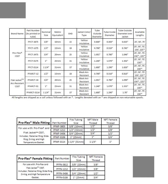
Yellow JacketTM
CSST, is designed to convey all Natural and LP Gases throughout the structure and nearby outdoor appliances. All tubing is clearly marked with the following: Brand Name, Part Number, Maximum Gas Pressure Rating [5 psi], EHD, the Standard listed to, Listing
Marks, the words Fuel Gas, and "foot marks".
4
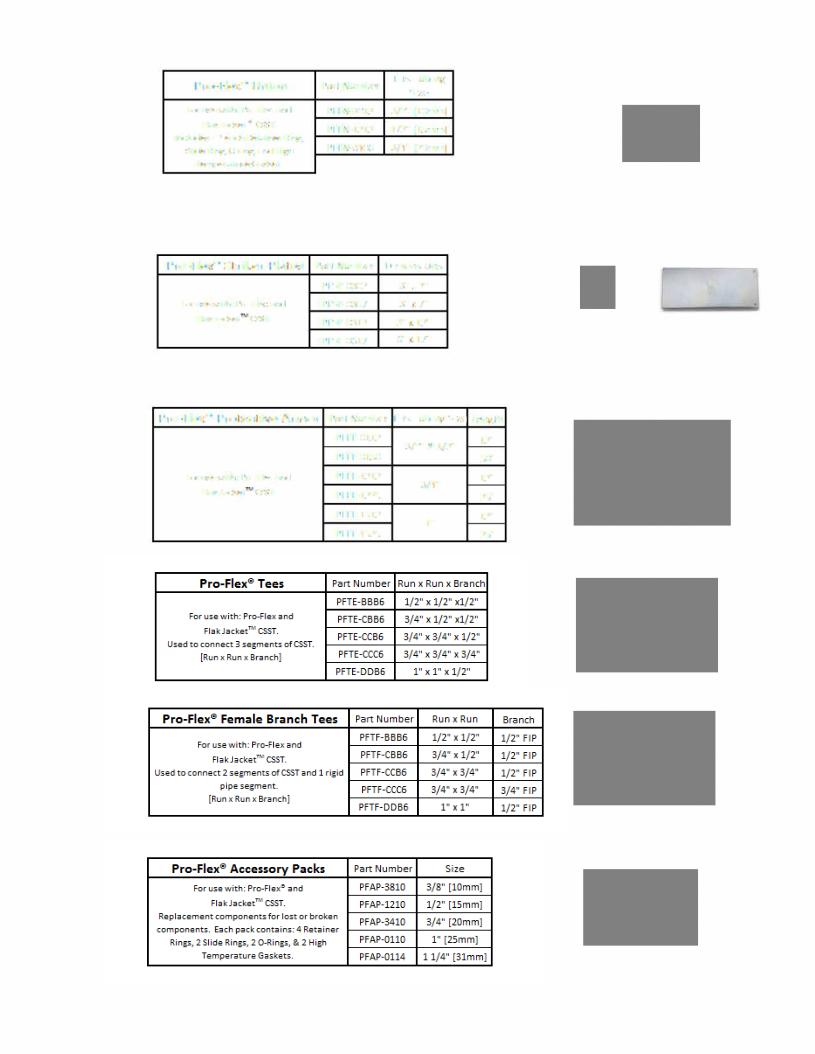
Pro Flex0 Union
F<>r use with: Pro-Flex and FlakJacketT'' CSST.
Includes: 2 each Retainer Ring,
Slide Ring, 0-ring, and High
Temp.erature Ga.s.ket.
Pro,-Flex0 Striker Plates
F<>r use with: Pro-Flex and
FlakJacket CSSi.
Part Number |
Fits Tubing |
|
Size |
||
|
||
PFFN-3812 |
3/8" [10mm] |
|
PFFN-1212 |
1/2" [15mm] |
|
PFFN-3406 |
3/4" [20mm] |
Part Number Dimensions
PFSP-0302 |
3" X 2" |
PFSP-0-307 |
3" X 7" |
PFSP-0312 |
3", X 12" |
PFSP-0617 |
,6"x17" |
Pro,-Flex0 Prote,ctive Armor |
Part Number Fits Tubing Size Length |
||
|
PFFF-0112 |
3/8" & 1/2" |
1.2" |
|
|
||
|
|
|
|
|
PFFF-0150 |
|
50' |
F<>r use with: f>ro-Flex and |
PFFF-121.2 |
3/4" |
1.2" |
FlakJa{jket CSST |
|
|
|
PFFF-1225, |
|
25' |
|
|
|
||
|
PFFF-15,1.2 |
1" |
1.2" |
|
|
|
|
|
PFFF-15,25, |
|
25' |
5

Additional Items approved as Part of the Pro-Flex® Flexible Piping System
6
7

3.0 System Configuration & Sizing
Configuration & Sizing
Prior to piping installation, refer to building plans or prepare a sketch showing the location of the appliances, the various appliance load demands, point of delivery (location of gas meter or second stage LP regulator), and possible piping routes. Appliance load demand data can be obtained from the manufacturers name-plate located on each appliance, or provided to the system designer by the builder/contractor.
a)Determine the local piping restrictions prior to installing the flexible gas piping. Confirm that the local administrative authority has accepted the use of flexible gas piping. Corrugated Stainless Steel Tubing has been accepted by most major code bodies, but local or state adoption of these codes often lags behind. Check with the local administrative authority.
b)Determine metered (supply) pressure.
Natural Gas: [Check with the local gas utility to determine the pressure supplied by the meter.]
•Standard low-pressure supply throughout the USA and Canada is typically 6-7 inches water column (also designated as 1/4 PSI or 4 ounces).
•Higher pressure supply such as 14 inches w.c. (1/2 PSI) and 2 PSI provide significant CSST size reduction. Check with the local gas utility for the availability of elevated pressure.
Propane (Liquefied Petroleum Gas): [Check with the propane supplier to determine the pressure supplied]
•LP is typically supplied within residential buildings at 11 inches w.c. This pressure is set at the second stage regulator.
•Elevated pressure settings from 14 inches w.c. to 2 PSI and 5 PSI also provide CSST sizereductions. Check with the propane gas supplier for available pressure.
c)Determine the total capacity needed for all appliances. CFH/BTUH equivalents for natural gas or propane flow can be obtained from the local gas utility or propane supplier. The capacity tables within this guide or any approved CSST tables should be used to determine pipe sizing needed to meet BTUH input load requirements.
•For natural gas with a specific gravity of 0.60, one cubic foot per hour (1 CFH) is approximately 1,000 BTUH.
•For propane gas with a specific gravity 1.52, one cubic foot per hour (1 CFH) is approximately 2,500 BTUH.
8
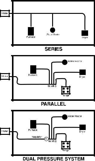
3.1.a Series and Parallel (Low Pressure) Systems
DETERMINE TOTAL CAPACITY NEEDED FOR APPLIANCES.
Data can be obtained from the manufacturers nameplate located on the gas appliance. BTU equivalents for CFH can be obtained from the local utility. In most cases, one Cubic Foot per Hour (1 CFH) is estimated to be 1,000 BTUH heating value (natural gas) and Propane has a heating value around 2,500 BTUH, making the capacity tables easy to utilize with appliance BTU input loads.
DETERMINE THE TYPE OF PIPING LAYOUT WHICH BEST FITS THE INSTALLATION
SERIES SYSTEMS
A series layout is the most common arrangement utilized for rigid pipe systems for low pressure. These usually consist of a main run (header) with tees branching off to each appliance. In a traditional series system, the service pressure down stream of the meter is typically less than 1/2 PSI.
The minimum pressure supplied to any given appliance is an important consideration. To operate properly, most Natural Gas appliances require a minimum of 4”WC pressure and most Propane (Liquefied Petroleum) appliances require a minimum of 10”WC pressure. Allowable pressure drop along any particular run may be dictated by local code restrictions.
PARALLEL SYSTEMS
In a parallel system, appliances are serviced by individual runs that stem off from a central distribution manifold. A main run from the meter supplies the manifold. The manifold station is located close to the greatest load, typically the boiler or furnace. A parallel layout is most likely to be used in 1/4 to 1/2 psi systems.
3.1.b Dual Pressure Systems
A dual pressure system incorporates two operating pressures downstream from the meter. The first pressure, set by the service regulator at the meter, is usually 2 psi, but can be higher or lower depending on code restrictions and gas company policy. This part of the system is sized separately and ends at the pounds-to- inches regulator inlet. The allowable pressure loss for this part of the system must be added to the effect of the regulator to determine the available pressure at the regulator outlet. See chart page 36, Regulator Capacity Table.
The second pressure, at the outlet of the pounds-to- inches regulator is under 1/2 PSI, usually 8”WC for natural gas and 11”WC for propane. Generally, a parallel system requires a higher total footage of smaller diameter tubing and fewer fittings compared to a series layout.
MULTI-UNIT APARTMENT BUILDING
9

Multiple Manifold Systems
For those installations in which the energy load demand is large or the appliances are installed throughout the structure with long distances from the meter, a multiple manifold system may be used. Elevated pressure systems are a safe, efficient method of providing for larger BTU load demands while maintaining smaller pipe diameters.
MULTIPLE MANIFOLD SYSTEMS
Combination Steel/CSST System (Hybrid)
In a hybrid system, corrugated stainless steel tub- |
|
ing is used in combination with rigid pipe or cop- |
|
per tubing. In lower pressure systems it is often |
|
advantageous to use both CSST and rigid pipe to |
|
help minimize pressure drops typically encountered |
|
on systems with high loads and/or long runs. |
|
Pro-Flex® Flexible Gas Piping systems [both Pro-Flex® & l |
k |
Flak JacketTM] are approved for use in combination with all approved fuel gas-piping materials by using approved pipe threads at the interface.
HYBRID SYSTEM
Elevated Pressure System
In a complete elevated pressure system, corrugated stainless steel tubing is used to deliver pressures in excess of 1/2 psi to a pounds-to-inches regulator positioned directly in front of each appliance regulator. This is an alternate method of installation used to minimize pressure drops typically encountered on systems with high loads and/or long runs.
ELEVATED PRESSURE SYSTEM
10

ALLOWABLE PRESSURE DROP:
Pro-Flex® gas piping systems [both Pro-Flex® CSST and Flak JacketTM] are required to be “tested, listed and installed" in accordance with the ANSI/CSA standard for fuel gas piping systems using corrugated stainless steel tubing, ANSI LC-1/ CSA 6.26. This standard, among other things, requires the manufacturer to provide installation instructions including the necessary pipe sizing tables and methods.
With respect to gas piping sizing, the intent of all model codes is to ensure there is sufficient gas volume and gas pressure supplied to the appliance for proper operation.Language from the International Fuel Gas Code clearly illustrates this point.
“Allowable pressure drop-The design pressure loss on any piping system under maximum probable flow conditions, from point of delivery to the inlet connection of the equipment, shall be such that the supply pressure at the equipment is greater than the minimum pressure required for proper equipment operation.”
Natural gas appliances are typically designed to operate with a minimum inlet pressure of 4.0 inches water column. Propane appliances are typically designed to operate with a minimum inlet pressure of 10.0 inches water column.
The natural gas capacity tables published by Pro-Flex, LLC, for use with Pro-Flex® and Flak JacketTM CSST, shall be used to provide for no less than 5” water column pressure to the appliance inlet. The propane capacity tables shall be used to provide no less than 10.5” water column pressure to the appliance inlet.
This can be done by subtracting the desired appliance inlet pressure (5” WC for NG, 10.5” WC for LPG) from the gas source pressure (gas meter for NG, second stage regulator for LPG) to get allowable pressure drop. Use the Pro-Flex® capacity table labeled with the appropriate allowable pressure drop and gas type. This will result in an additional pressure drop capacity over the commonly used 1/2” WC drop associated with the Longest Run Method.
Allowable Pressure Drop along any particular run may be dictated by local codes.
Reference Data for Proper System Sizing:
PRESSURE CONVERSION FACTORS |
FUEL GAS INFORMATION |
1/4 |
psi = |
6.921 in w.c. = |
(approx. 7” WC) |
Natural Gas |
Propane |
||
1/2 |
psi = |
13.842 in w.c. = |
(approx. 14” WC) |
BTU per Cubic Foot = |
1000 |
2516 |
|
|
|
|
|
|
|
|
|
1 |
psi = |
27.684 in w.c. = |
(approx. 28” WC) |
Specific Gravity = |
0.60 |
1.52 |
|
2 |
psi = |
55.368 in w.c. = |
(approx. 56” WC) |
Note: to determine the CFH of Natural Gas, |
|||
|
|
|
|
divide by BTU load by 1000. To determine the |
|||
5 |
psi = |
138.42 in w.c. = |
(approx. 140” WC) |
||||
CFH of Propane, divide the BTU by 2516 |
|||||||
11

3.2 Sizing Methods and Examples
SIZING PROCEDURES FLAK JACKETTM & PRO-FLEX® CSST, FLEXIBLE GAS TUBING
LONGEST LENGTH METHOD EXAMPLE #1
This is a low-pressure series system with four natural gas appliances. The utility company supply pressure exiting the meter is 6 inches water column, and the maximum allowable pressure drop across the longest length from the meter to the farthest appliance is 1/2 inch water column. The gas supplied has a specified gravity of .60 and an energy content of 1 cubic foot per hour equals 1,000 BTU per hour.
APPLIANCE LOADS |
+GAS LOAD |
LENGTH OF RUN |
||||||
FURNACE |
|
75 CFH (75,000 BTUH/1000 PER CFH) |
14 FEET |
|||||
OVEN/RANGE |
45 CFH (45,000 BTUH/1000 PER CFH) |
20 FEET |
||||||
DRYER |
|
25 CFH (25,000 BTUH/1000 PER CFH) |
38 FEET |
|||||
WATER HEATER |
24 CFH (24.000 BTUH/1000 PER CFH) |
50 FEET |
||||||
TOTAL.................................................. |
|
|
169 CFH |
|
|
|
||
LENGTH OF EACH RUN |
|
|
|
|
||||
A |
= |
8 |
FEET |
EXAMPLE: |
|
|
|
|
B |
= |
10 |
FEET |
Furnace: A (8 ft) + F (6 ft) = 14 FEET |
|
|
|
|
C |
= |
12 |
FEET |
Oven/Range: A (8 ft) + B (10 ft) + E (2 ft) = 20 FEET |
||||
D |
= |
20 |
FEET |
Dryer: A (8 ft) + B (10 ft) + C (12 ft) + G (8 ft) = 38 FEET |
||||
E |
= |
2 |
FEET |
Water Heater: A (8 ft) + B (10 ft) + C (12 ft) + D (20 ft) = 50 FEET |
||||
|
|
|
|
|
|
|
||
F |
= |
6 |
FEET |
THE LONGEST RUN IS FROM THE METER TO THE WATER HEATER; OVER 50 FEET. |
||||
G = |
8 |
FEET |
|
|
|
|
|
|
SIZING SECTION A:
Length A must be sized to handle thetotal load of all appliances and the total pressure drop from the meter to the farthest applianceThe. total appliance load is 169 CFH. Using the longest length sizing method, the length is 50 ft. to the water heater. Referring toTable 1, (6" WC inlet pressure and 1/2" WC pressure drop) under the 50 ft. length column, we find that 1 inch size has the flow capacity exceeding 169 CFH (171 CFH). Use 1" tubing to run Section A.
SIZING SECTION B:
Section B must supply the water heater, dryer and range. The total pressure drop for the system is considered to be from the meter to the water heater (farthest appliance). The total appliance load is 24+25+45 = 94 CFH. Using the longest length sizing method, the length is 50ft. (distance from meter to water heater). Referring toTable 1 under the 50 ft. length column, we find that size 1 inch has flowcapacity over 94 CFH (171 CFH). Use 1" tubing to run Section B.
SIZING SECTION C:
Section C must supply the water heater and dryer. The total appliance load is 24+25 = 49 CFH. Using the longest length method, the length is 50 ft. Referring to Table 1 under the 50 ft. length column, we find that 3/4 inch has flow capacity above the 49 CFH (89 CFH) Use 3/4" tubing to run Section C.
SIZING SECTION D:
Section D must supply the water heater. The total appliance load is 24 CFH. Using the longest method, the length is 50 ft. Referring toTable 1 under the 50 ft. length column, we find that 1/2 inch has flow capacity above 24 CFH (32 CFH). Use 1/2" tubing to run Section D.
SIZING SECTION E:
The total appliance load is 45 CFH. Using the longest length method, the length is 50 ft. Referring toTable 1 under 50 ft. length column, we find that 3/4" has flow capacity above 45 CFH (89 CFH) Use 3/4" tubing to run Section E.
SIZING SECTION F:
The total appliance load is 75 CFH. Using the longest length method, the length is 50 ft. Referring toTable 1 under 50 ft. length column,we find that 3/4" has flow capacity above 75 CFH (89 CFH) Use 3/4" tubing to run SectionF.
SIZING SECTION G:
The total appliance load is 25 CFH. Using the longest length method, the length is 50 ft. Referring toTable 1 under 50 ft. length column, we find that 1/2" has flow capacity above 25 CFH (32 CFH) Use 1/2" tubing to run Section G.
12

EXAMPLE #2, MEDIUM PRESSURE PARALLEL SYSTEM
This is a medium-pressure parallel system which includes a distribution tee manifold. The natural gas supply pressure is 1/2 psig and the maximum allowable pressure drop from the meter to the farthest appliance is 6" WC.
Medium Pressure (1/2 psig) Natural Gas (Parallel System)
Appliance |
|
|
|
Loads |
Lengths |
size |
|
|
|
|
|
|
A = |
10 FT |
3/4" |
Oven/Range 45 CFH |
B = |
20 FT |
3/8" |
Furnace = 75 CFH |
C = |
5 FT |
3/8" |
Dryer = 25 CFH |
D = |
35 FT |
3/8" |
Water Heater = 24CFH |
E = |
50 FT |
3/8" |
TOTAL CFH.... 169 CFH
SIZING, SECTION A:
Determine distance from the meter to the farthest appliance (water heater 60 ft.) Determine the total appliance load supply by Section A (169 CFH). Referring toTable 4 under the 60 ft. length column, we find 3/4 inch has flow capacity above 169 CFH (274 CFH). Use 3/4" tubing to run Section A.
SIZING SECTION B:
Section B supplies the oven/range. The total pressure drop is considered from the meter to the oven/range. The total appliance load is 45 CFH and the length is 10 ft + 20 ft.= 30 feet total. Referring toTable 4 under the 30 ft. length col-umn, we find that 3/8 inch has a flow capacity above 45 CFH (94 CFH). Use 3/8" tubing to run Section B.
SIZING SECTION C:
Section C supplies the furnace. The total appliance load is 75 CFH and the total length is 10 ft. + 5 ft. = 15 ft total. Referring to Table 4 under the 15 ft. length column. We find that 3/8 inch has a flow capacity above
75 CFH (134 CFH) Use 3/8" tubing to run Section C.
SIZING SECTION D:
Section D supplies the dryer. The total appliance load is 25 CFH and the total length from the meter is
10 ft. + 35 ft. = 45 feet total. Referring toTable 4 under the 45 ft. length column. Since 45 ft. does not appear in the table, use the next longest run column of 50 ft. We find that 3/8 inch has a flow capacity above 25 CFH (73 CFH) Use 3/8” tubing to run Section D.
SIZING SECTION E:
Section E supplies the water heater. The total appliance load is 24 CFH and the total length from the meter to appliance is 10 ft + 50 ft = 60 feet total. Referring toTable 4 under the 60 ft. length column, we find that 3/8 inch has a flow capacity above 24 CFH (65 CFH) Use 3/8" tubing to run Section E.
13

EXAMPLE #3 - ELEVATED DUAL PRESSURE SYSTEM
This is a 2 psig supply pressure parallel arrangement. The natural gas system incorporates a pressure reducing regulator with a distribution tee manifold located closely to several large capacity appliances. The inlet pressure downstream of the meter is 2 psig, and the designated maximum pressure drop from the meter to the reducing regulator is 1.0 psig. The outlet pressure from the regulator is set at 8 inches water column. A 3" WC pressure drop is used in sizing the tubing from the regulator outlet to each appliance. Specific gravity of the gas delivered is .60 and energy content is 1 CFH = 1,000 BTUH.
Elevated (2 psig) Dual Pressure Natural Gas (Parallel System)
Total load and regulator size:
Calculate the total appliance load and determine if one regulator has sufficient capacity to supply this load. One regulator is normally adequate when appliances are close together. When groups of high-load appliances are widely separated, it is often more economical to use one pressure reducing regulator to supply each appliance group. The total appliance load required is 169 CFH (169,000 BTUH).
The supply pressure from the meter is 2
psig and the designated pressure drop from the
APPLIANCE LOADS |
LENGTHS |
TUBE SIZE |
METER TO REGULATOR |
A= 10 FEET |
3/8" |
OVEN/RANGE = 45 CFH |
B = 20 FEET |
3/8" |
FURNACE = 75 CFH |
C = 5 FEET |
3/8" |
DRYER = 25 CFH |
D = 35 FEET |
3/8" |
WATER HEATER=24 CFH |
E = 50 FEET |
3/8" |
TOTAL........................................... |
169 CFH |
|
meter to the regulator is 1 psig; thus the
minimum inlet pressure to the regulator is 1 psig. Since the outlet pressure of the regulator is set at 8" WC, the expected pressure drop across the regulator is 20 inches WC (1 psig - 8" WC = 20" WC). A single 325-3 regulator has a flow rate capacity of 252 CFH. This capacity exceeds the system requirement of 169 CFH. In cases where the 325-3 regulator capacity is insufficient, a larger #325-5A regulator or parallel arrangement of two regulators should be used.
SIZING SECTION A (METER TO REGULATOR):
Section A must be sized to handle all appliances loads and supply the pressure reducing (pounds to inches) regulator. The total load is 169 CFH and the length is 10 ft. The supply pressure is 2 psig and the pressure drop is 1 psig. Referring to Table 5 (meter to regulator with 2 psig inlet and 1 psig drop) under the 10 ft. column, we find that 3/8 inch has capacity over 169 CFH (332 CFH). Use 3/8" tubing to run Section A. To size the other sections, the pressure source is the outlet of the pressure regulator rather than the meter. Use the low-pressure Table 3 (8.0" WC inlet with 3.0" WC drop) and size each section individually using the appliance load and run distance.
SIZING SECTION B
Section B supplies the oven/range. The load is 45 CFH and the distance between the regulator outlet and appliance is 20 ft. The total pressure drop is from the outlet of the reducing regulator to the oven/range. The outlet pressure from the regulator is 8" WC and the pressure drop is 3" WC. Referring to Table 3, under the 20 ft. length column, we find that an 8 inch has a flow capacity above 45 CFH (81 CFH). Use 3/8" tubing to run Section B.
SIZING SECTION C:
Section C supplies the furnace. The load is 75 CFH and the distance is 5 ft. Referring to Table 3, under the 5 ft. length column, we find that 3/8 inch has a flow capacity above 75 CFH (162 CFH). Use 3/8" tubing to run Section C.
SIZING SECTION D:
Section D supplies the dryer. The load is 25 CFH and the distance is 35 ft. Referring to Table 3, and since a 35 ft. length column does not exist, use the 40 ft. length column. We find that 318 inch has a flow capacity above 25 CFH (58 CFH). Use 3/8" tubing to run Section D.
SIZING SECTION E:
Section E supplies the water heater. The load is 24 CFH and the distance is 50 ft. Referring to Table 3, under the 50 ft. length column, we find that 3/8 inch has a flow capacity above 24 CFH (51 CFH). Use 3/8" tubing to run Section E.
14
COMBINATION STEEL/ CSST (Hybrid System)
(Hybrid system)
It is often to your advantage to use both CSST and rigid pipe to help minimize pressure drops typically encountered on systems with high loads and/or long runs. Flexible gas piping systems by Pro-Flex, LLC [both Pro-Flex®CSST and Flak JacketTM] are approved for use in combinations with approved gas piping materials by using approved pipe threads at the interface. For sizing use longest run method assuming the complete run is CSST.
15
 Loading...