

Page 1

SP5000 Series
(Display Module)
Installation Guide
Page 2
3
English
Safety Information
Important Information ....................................................................................... 5
Model Numbers
Model Numbers ...............................................................................................7
Overview
Package Contents............................................................................................ 8
About the Manual.............................................................................................9
Global Code .....................................................................................................9
Part Numbers and Functions
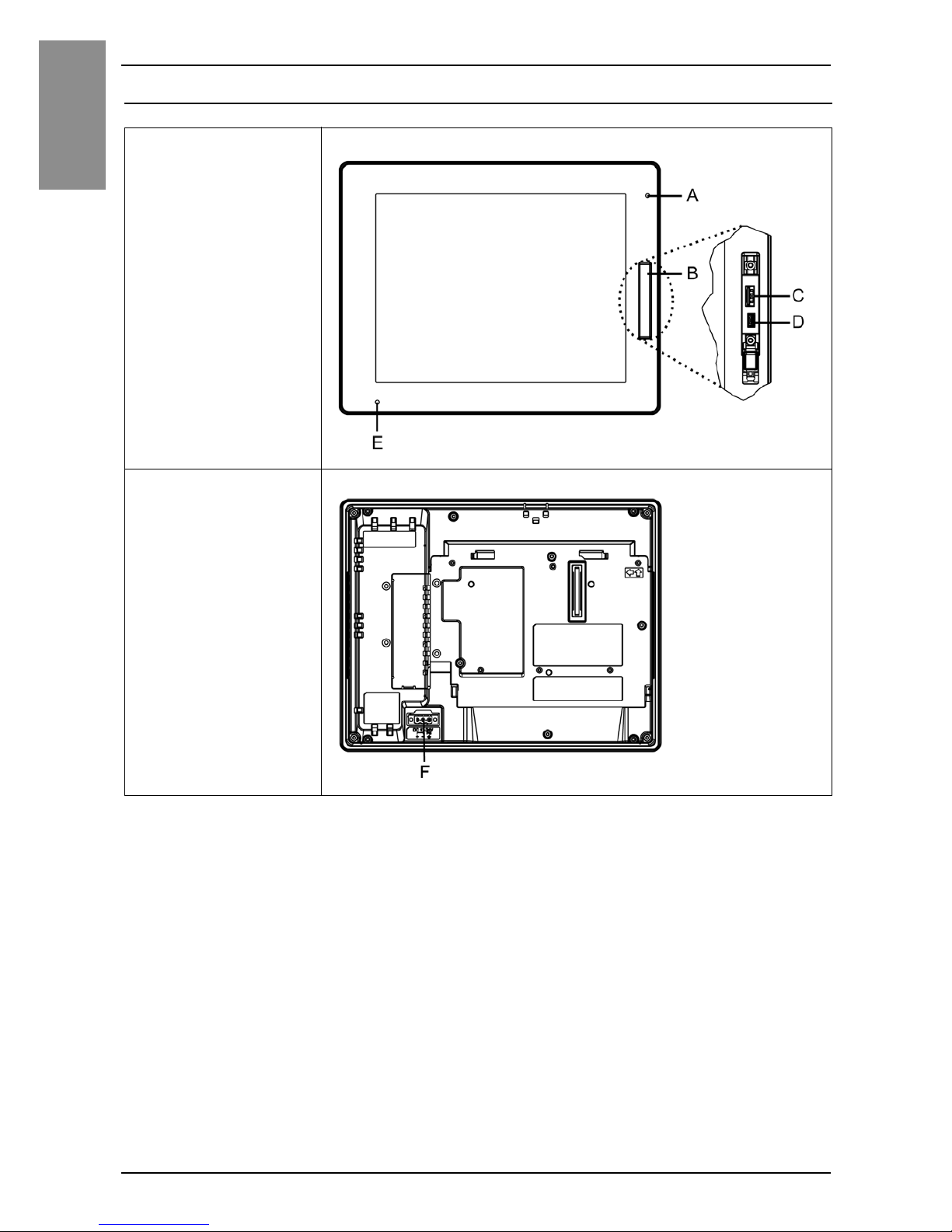
SP-5500TP ....................................................................................................10
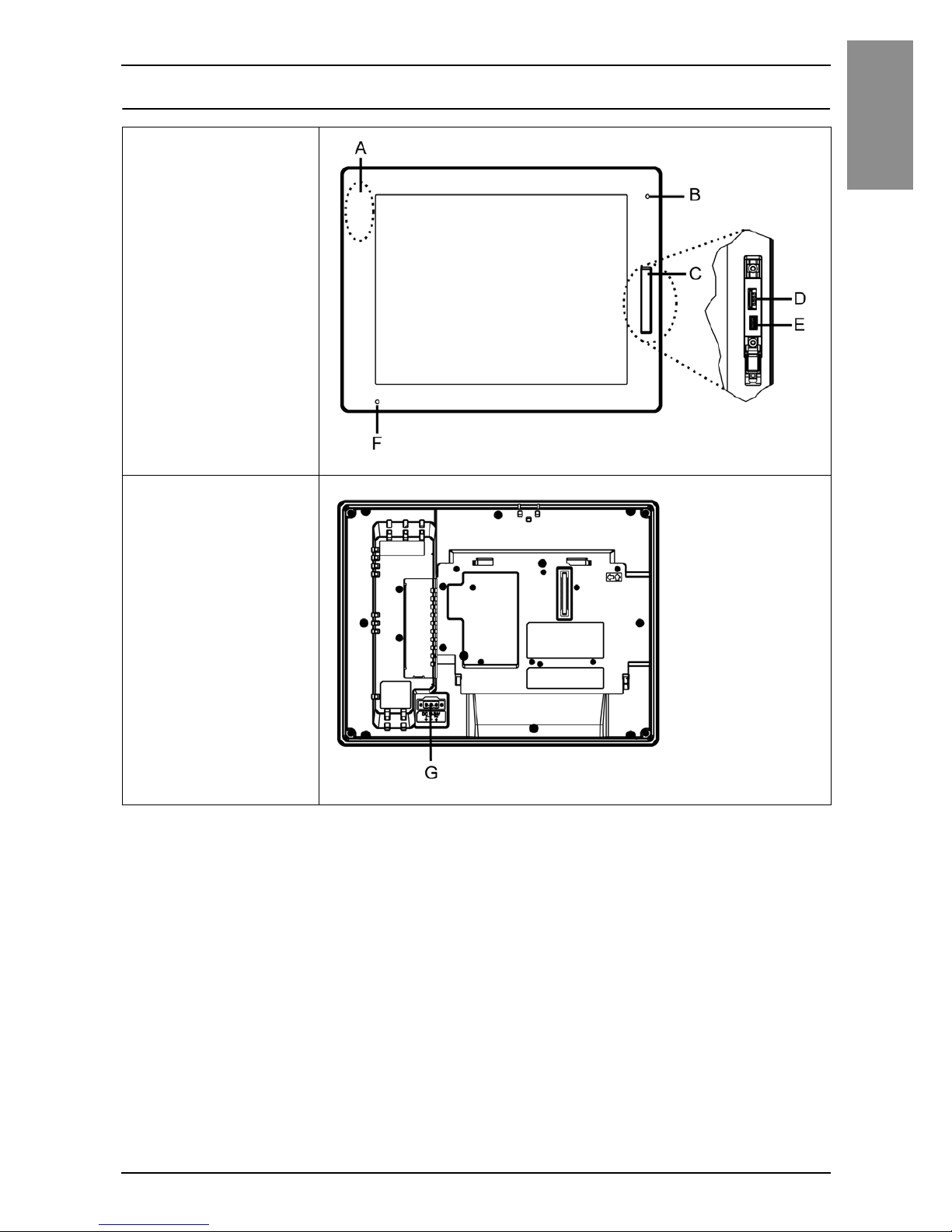
SP-5600TP/5660TP ...................................................................................... 11
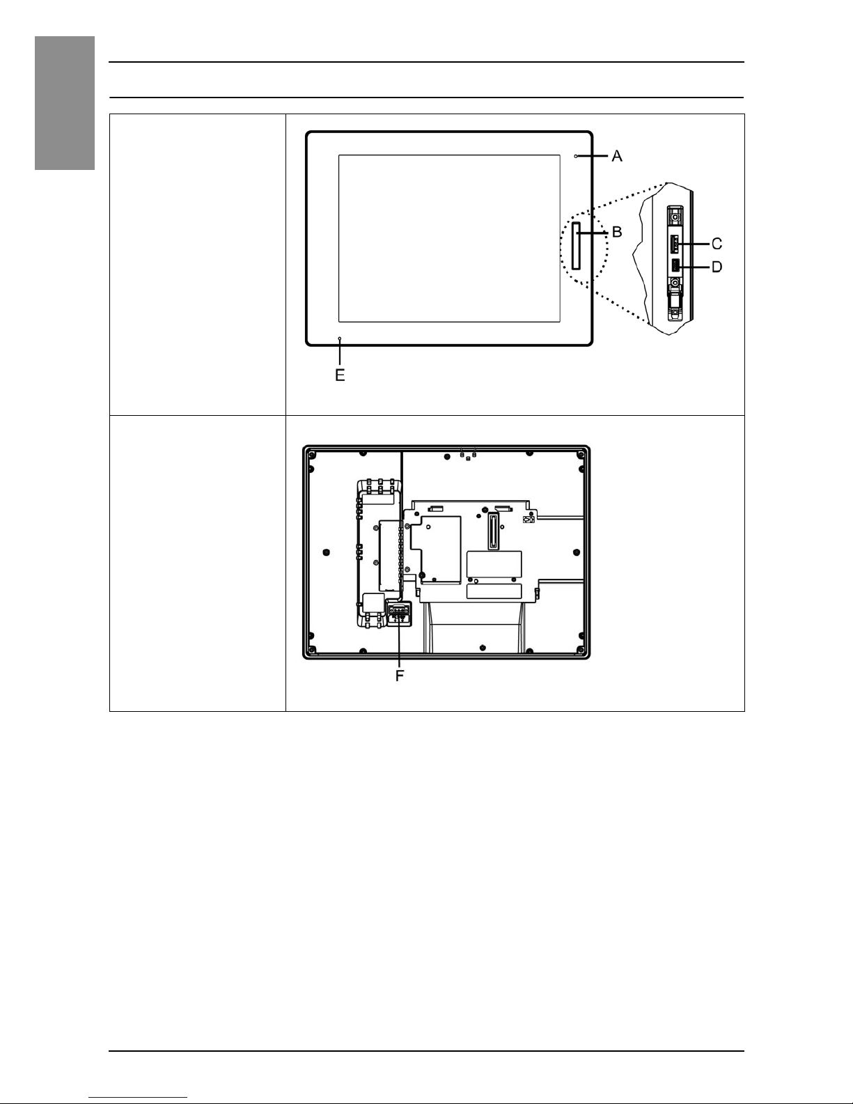
SP-5700TP ....................................................................................................12
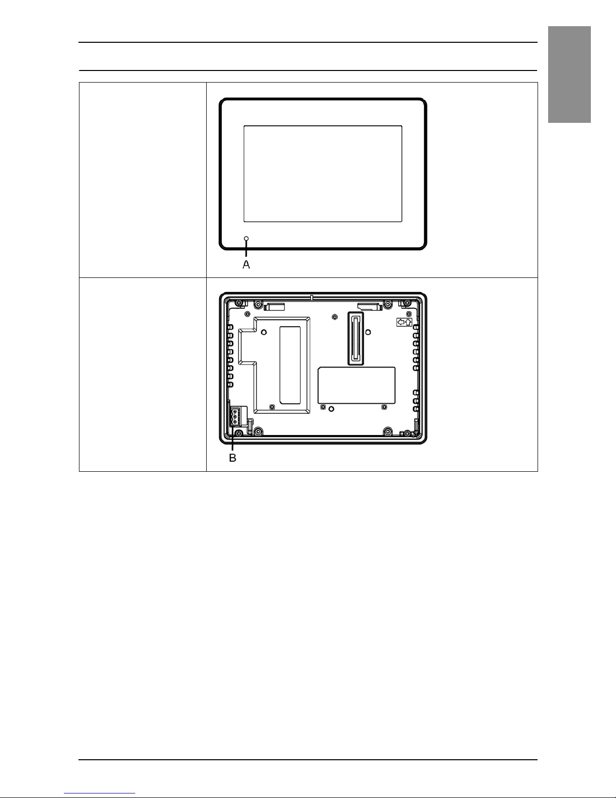
SP-5400WA .................................................................................................. 13
SP-5500WA .................................................................................................. 14
SP-5600WA .................................................................................................. 15
LED Indications ..............................................................................................16
Specifications
Electrical Specifications ................................................................................. 17
Environmental Specifications ......................................................................... 19
Installation
Panel Cut Dimensions....................................................................................20
Installation Requirements............................................................................... 21
Installation Procedure ....................................................................................27
Removal Procedure ....................................................................................... 31
Wiring
Wiring ............................................................................................................. 34
Front USB Cover
Front USB Cover ............................................................................................41
Please read the “Warning/Caution Information” on the attached
sheet before using the product.
Page 3

4
English
Front USB Port
Front USB Port............................................................................................... 43
Standards
Standards....................................................................................................... 46
Page 4
5
English
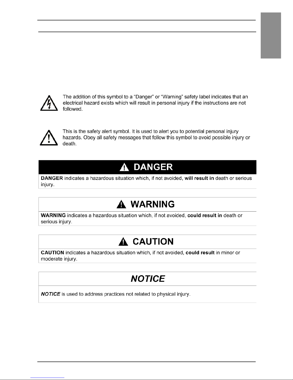
Safety Information
Important Information
Notice
Read these instructions carefully, and look at the equipment to become
familiar with the device before trying to install, operate, or maintain it. The
following special messages may appear throughout this documentation or on
the equipment to warn of potential hazards or to call attention to information
that clarifies or simplifies a procedure.
Page 5

6
English
Safety Information
PLEASE NOTE
Electrical equipment should be installed, operated, serviced, and maintained
only by qualified personnel. No responsibility is assumed by Pro-face for any
consequences arising out of the use of this material.
A qualified person is one who has skills and knowledge related to the
construction and operation of electrical equipment and its installation, and has
received safety training to recognize and avoid the hazards involved.
Page 6
7
English
Model Numbers
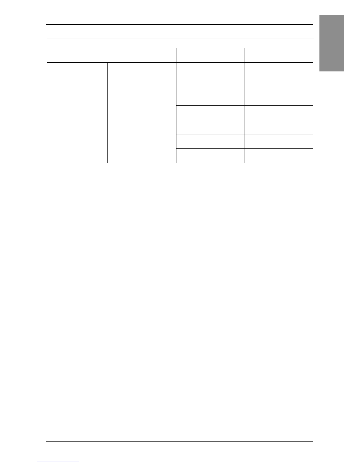
Model Numbers
NOTE: These models can be connected to all models of SP5000 Series Box Module. For
the model numbers of the Box Module, refer to the SP5000 Series (Box Module) Installation
Guide.
Series Model name Model number
SP5000 Series Premium Display SP-5500TP PFXSP5500TPD
SP-5600TP PFXSP5600TPD
SP-5660TP PFXSP5660TPD
SP-5700TP PFXSP5700TPD
Advanced Display SP-5400WA PFXSP5400WAD
SP-5500WA PFXSP5500WAD
SP-5600WA PFXSP5600WAD
Page 7
8
English
Overview
Package Contents
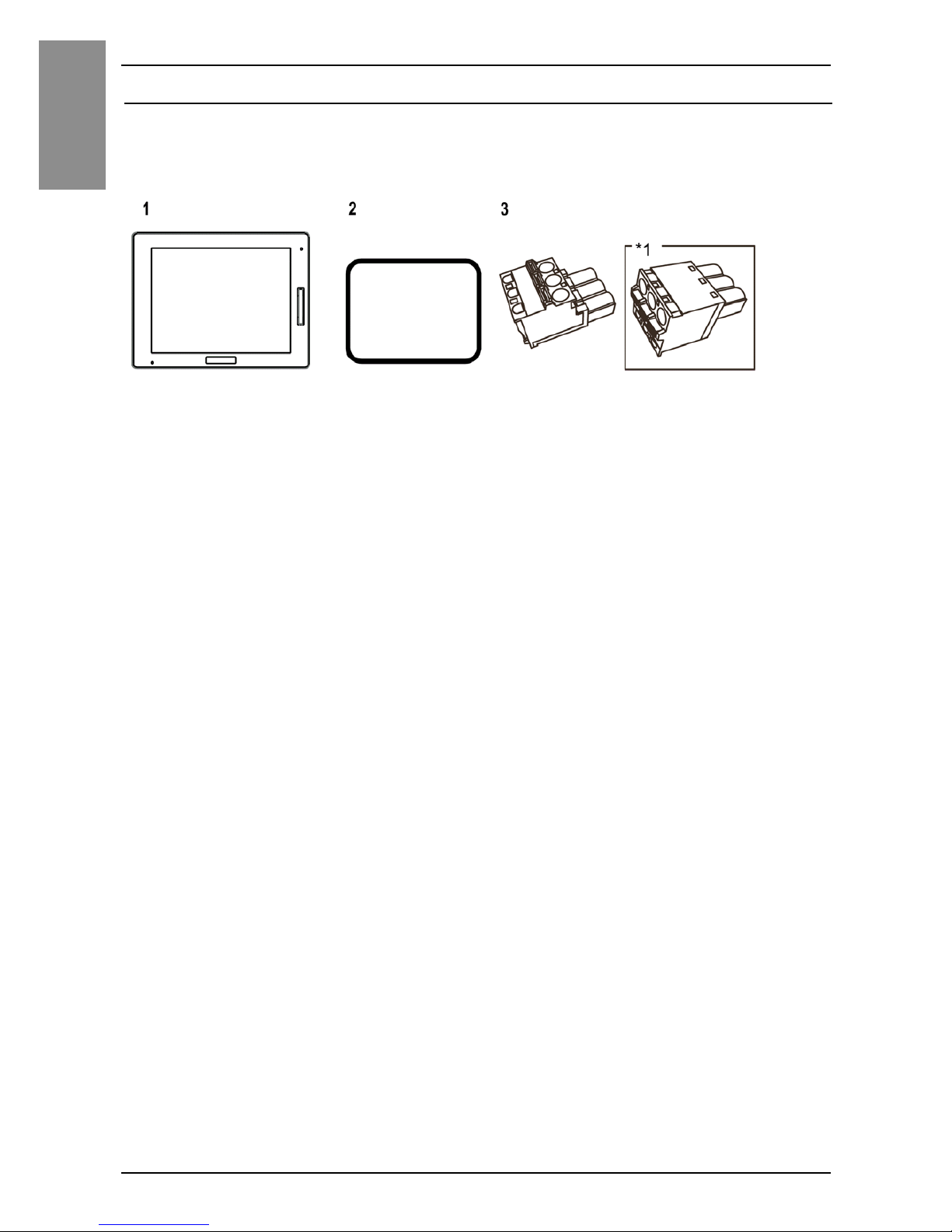
The following items are included in the package. Before using this product,
please confirm that all items listed here are present.
1 SP5000 Series Display Module: 1
2 Installation gasket: 1 (attached to this product)
3 DC power supply connector (right-angle type
*1
): 1
4 SP5000 Series (Display Module) Installation Guide (this guide): 1
5 Warning/Caution Information: 1
*1 Straight type for SP-5400WA
This product has been carefully packed, with special attention to quality.
However, should you find anything damaged or missing, please contact your
local distributor immediately.
Page 8

9
Overview
English
About the Manual
This manual describes wiring and installation procedures. For more detailed
information, refer to the SP5000 Series Hardware Manual.
You can download the manual from our website “Otasuke Pro!” at
http://www.pro-face.com/trans/en/manual/1001.html
Global Code
A global code is assigned to every Pro-face product as a universal model
number.
For more information on product models and their matching global codes,
please refer to the following URL.
http://www.pro-face.com/trans/en/manual/1003.html
Page 9
10
English
Part Numbers and Functions
SP-5500TP
A: Brightness sensor
B: Front USB cover
C: USB (Type A) interface
D: USB (mini-B) interface
E: Status LED (see page 16)
F: Power plug connector
Front
Rear
Page 10
11
Part Numbers and Functions
English
SP-5600TP/5660TP
A: Wireless LAN antenna (only for SP-5660TP)
B: Brightness sensor
C: Front USB Cover
D: USB (Type A) interface
E: USB (mini-B) interface
F: Status LED (see page 16)
G: Power plug connector
Front
Rear
Page 11
12
English
Part Numbers and Functions
SP-5700TP
A: Brightness sensor
B: Front USB cover
C: USB (Type A) interface
D: USB (mini-B) interface
E: Status LED (see page 16)
F: Power plug connector
Front
Rear
Page 12
13
Part Numbers and Functions
English
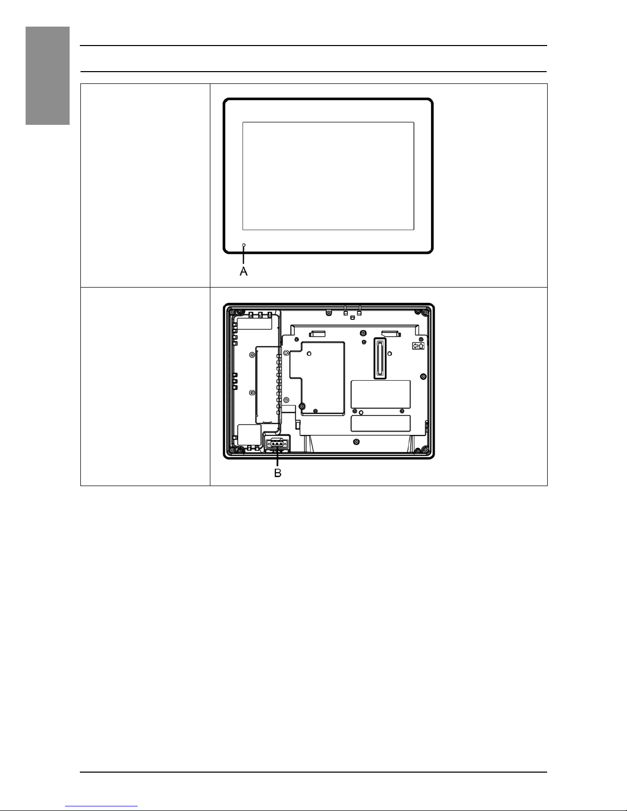
SP-5400WA
A: Status LED (see page 16)
B: Power plug connector
Front
Rear
Page 13
14
English
Part Numbers and Functions
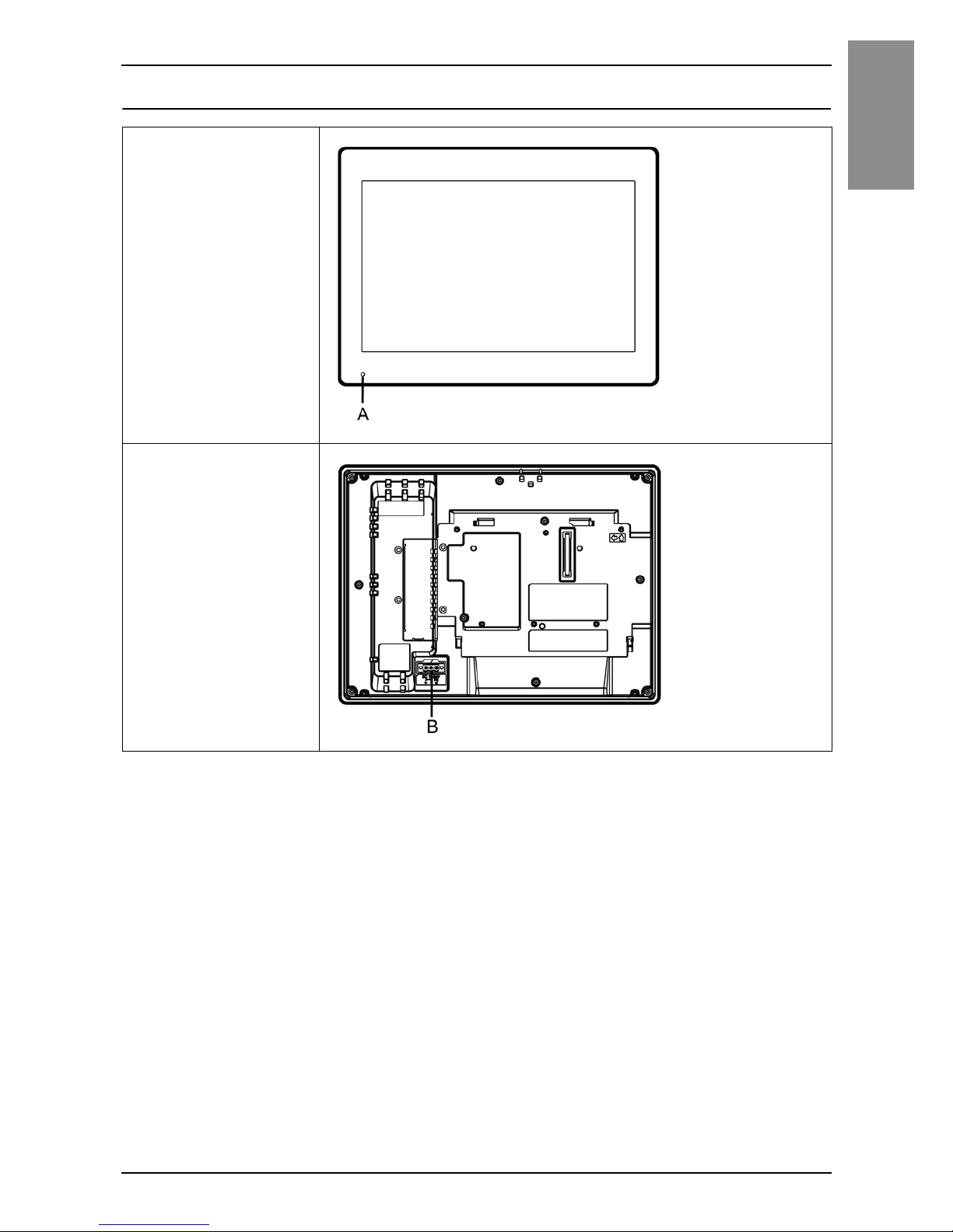
SP-5500WA
A: Status LED (see page 16)
B: Power plug connector
Front
Rear
Page 14
15
Part Numbers and Functions
English
SP-5600WA
A: Status LED (see page 16)
B: Power plug connector
Front
Rear
Page 15
16
English
Part Numbers and Functions
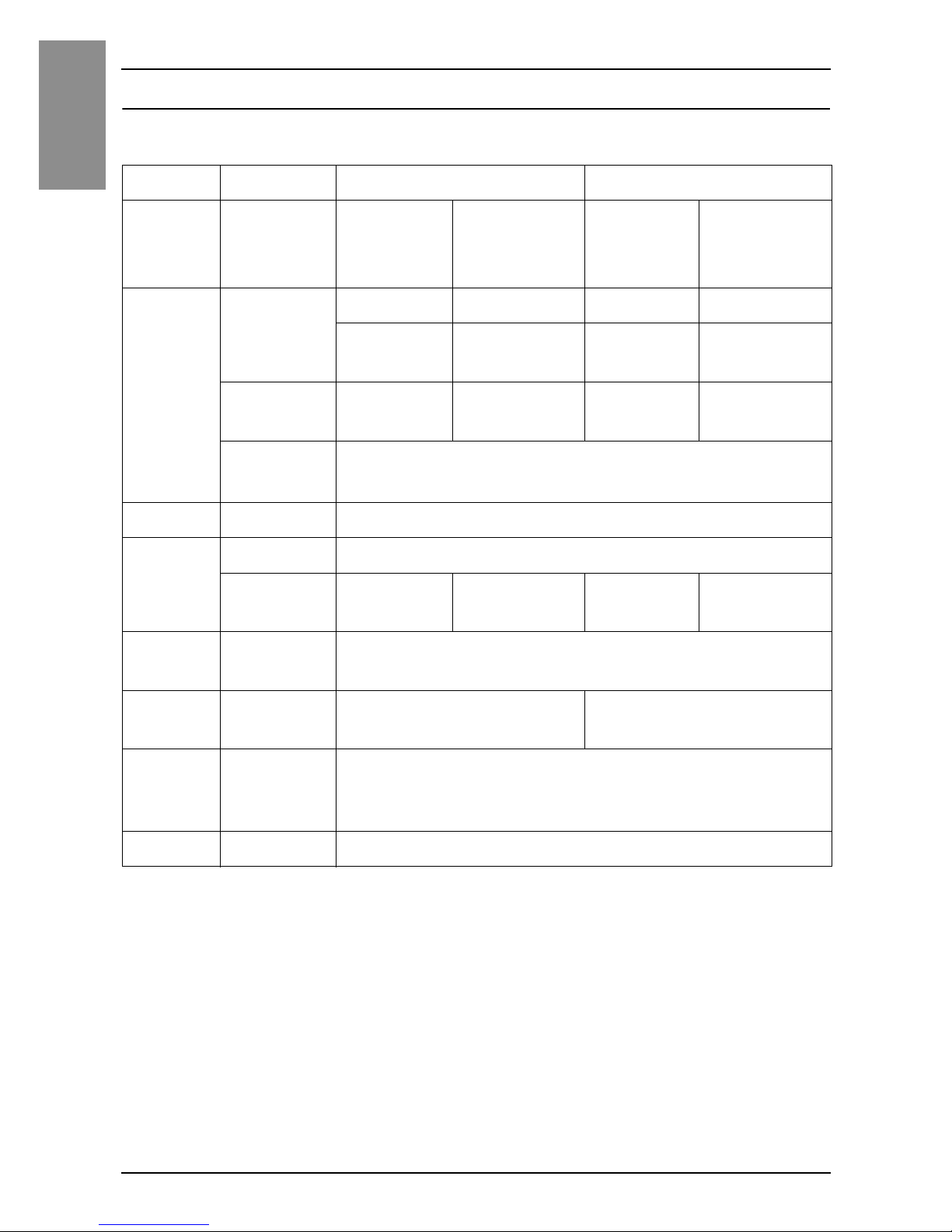
LED Indications
Status LED
*1 Only when your screen editing software supports the Logic Program.
*2 Make sure your screen editing software supports the function.
NOTE: When Open Box is connected, even if its operating system is shut down, the status
LED on the Display Module will display red if connected to a power supply.
Color Indicator
Connected to Power Box
Connected to Open Box
HMI
Operation
Logic
Program
Operation
*1
HMI
Operation
Logic
Program
Operation
*1
Green ON Offline – Offline –
In
operation
RUN In
operation
RUN
Flashing
*1
In
operation
STOP In
operation
STOP
LED
fade
*2
Backlight OFF (Standby Mode)
Orange Flashing Software starting up
Red ON Power is ON.
Flashing
*1
In
operation
Major error In
operation
Major error
Red/
Green
Alternating Box Module connection error
Orange/
Red
Alternating SD Card boot error –
Orange/
Red/
Green
Alternating Display Module internal error
– OFF Power is OFF.
Page 16
17
English
Specifications
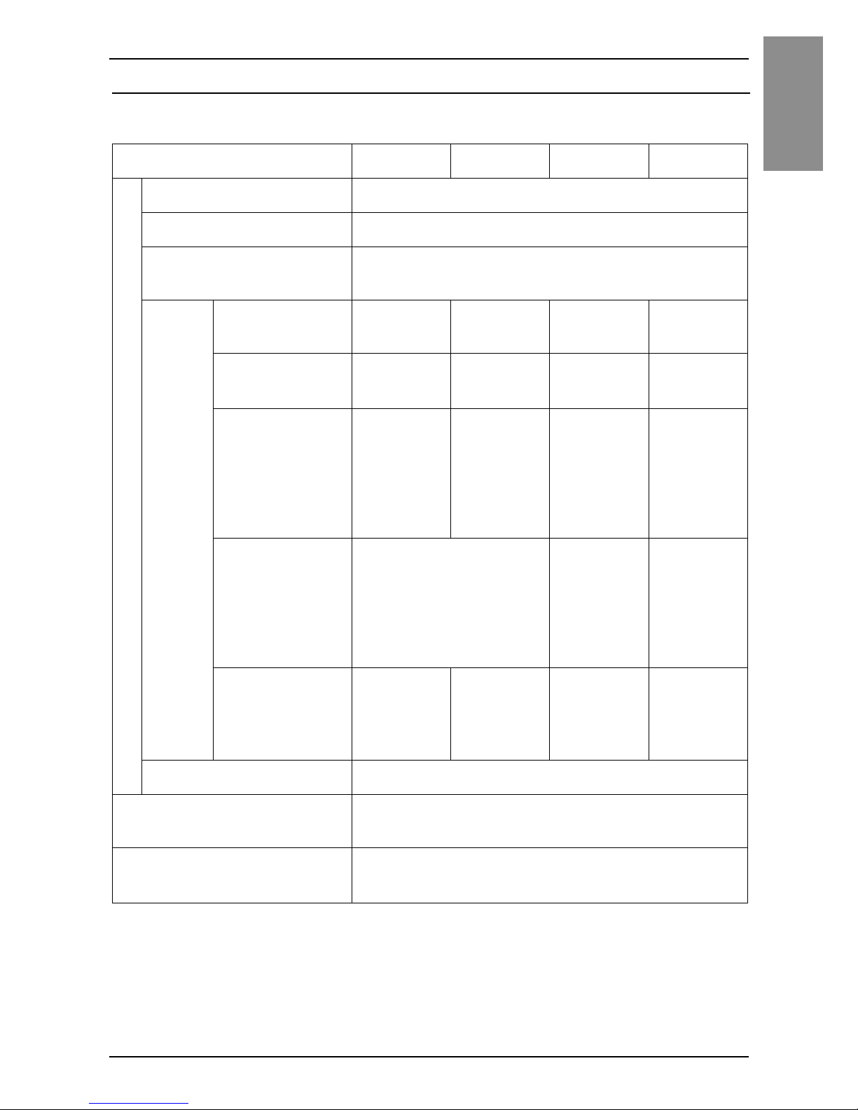
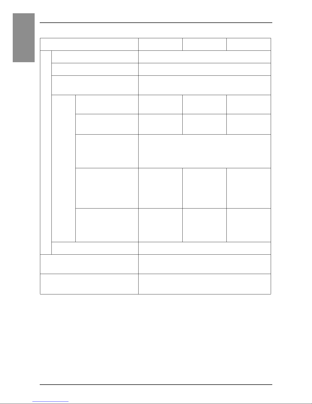
Electrical Specifications
SP-5500TP/5600TP/5660TP/5700TP
*1 The power consumption for the combined unit of Box Module and Display Module equals
the sum of the power consumption for the Modules.
Specification
SP-5500TP SP-5600TP SP-5660TP SP-5700TP
Power supply
Rated input voltage 12...24 Vdc
Input voltage limits 10.8...28.8 Vdc
Voltage drop 12 Vdc: 1.25 ms or less
24 Vdc: 5 ms or less
Power consumption
(primary power supply
including power loss)
Max (including
Box Module)
50 W56 W58 W57 W
Max (Display
Module only)
*1
15 W21 W23 W22 W
When power is
not supplied to
external
devices
(Display
Module only)
*1
12 W or
less
18 W or
less
20 W or
less
19 W or
less
When screen
turns off the
backlight
(Stand-by
Mode) (Display
Module only)
*1
6 W or less 8 W or
less
6 W or
less
When screen
backlight 20%
(Display
Module only)
*1
8 W or
less
11 W o r
less
13 W or
less
11 W o r
less
In-rush current 30 A or less
Voltage endurance 1,000 Vac, 20 mA for 1 minute (between
charging and FG terminals)
Insulation resistance 500 Vdc, 10 MΩ or more (between charging
and FG terminals)
Page 17
18
English
Specifications
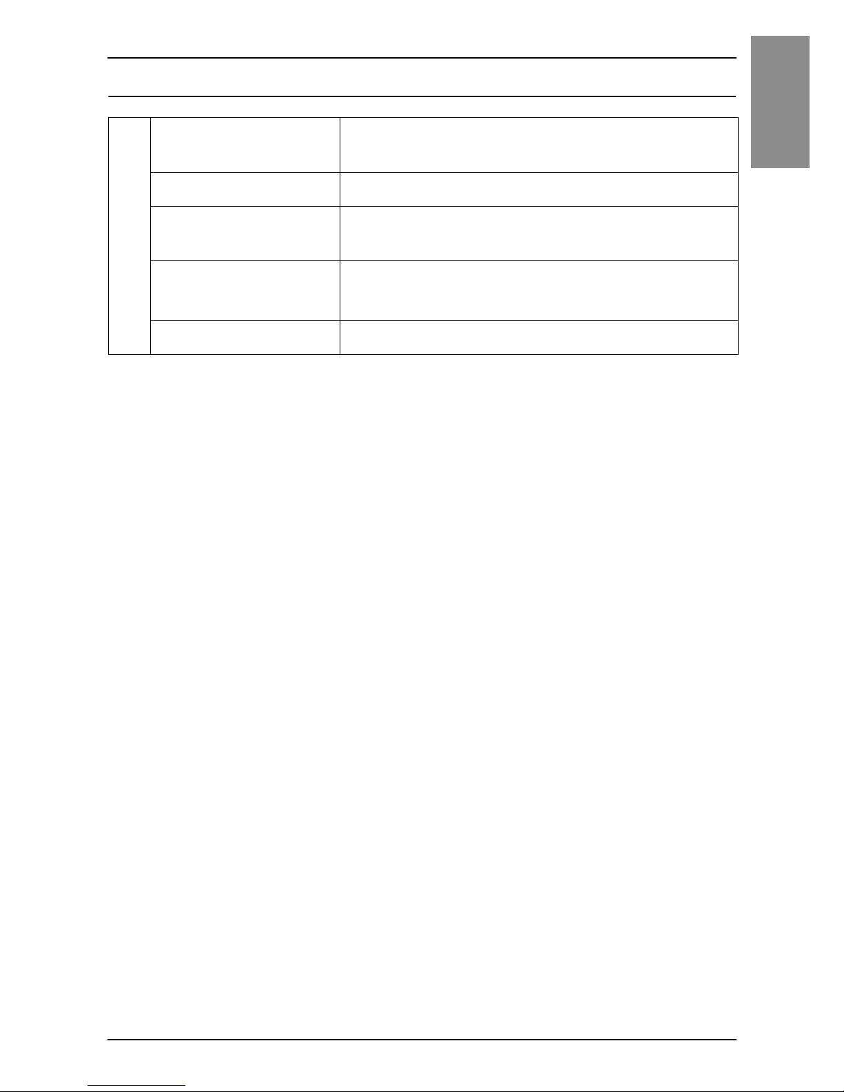
SP-5400WA/5500WA/5600WA
*1 The power consumption for the combined unit of Box Module and Display Module equals
the sum of the power consumption for each of the Modules.
Specification
SP-5400WA SP-5500WA SP-5600WA
Power supply
Rated input voltage 12...24 Vdc
Input voltage limits 10.8...28.8 Vdc
Voltage drop 12 Vdc: 1.25 ms or less
24 Vdc: 5 ms or less
Power consumption
(primary power supply
including power loss)
Max (including Box
Module)
41 W 43 W 45 W
Max (Display
Module only)
*1
6.5 W 8.5 W 11.5 W
When power is not
supplied to external
devices (Display
Module only)
*1
–
When screen turns
off the backlight
(Stand-by Mode)
(Display Module
only)
*1
2 W or less 2.5 W or less 2.5 W or less
When screen
backlight 20%
(Display Module
only)
*1
4 W or less 5 W or less 6 W or less
In-rush current 30 A or less
Voltage endurance 1,000 Vac, 20 mA for 1 minute (between
charging and FG terminals)
Insulation resistance 500 Vdc, 10 MΩ or more (between
charging and FG terminals)
Page 18
19
Specifications
English
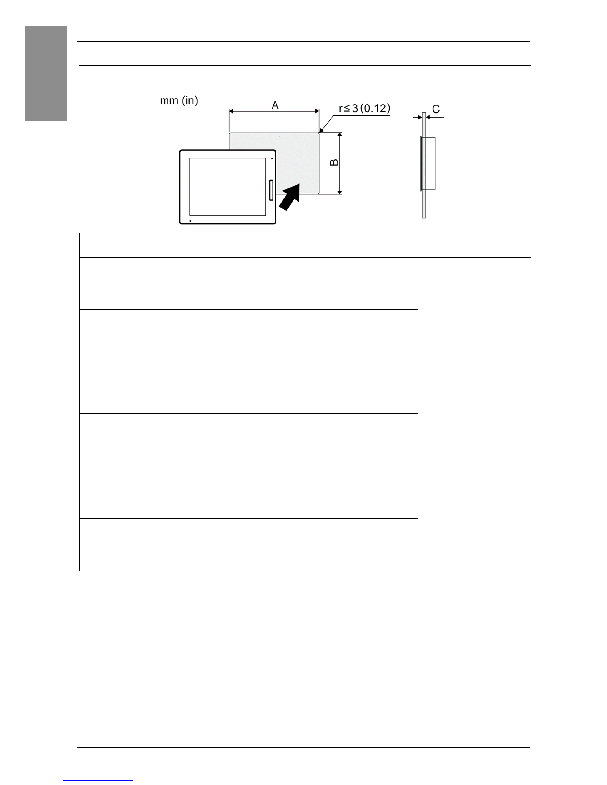
Environmental Specifications
NOTE: When using any of the options for this product, check the specifications for special
conditions or cautions that may apply to this product.
Physical environment
Surrounding air
temperature
0...60 °C (32...140 °F)
Storage temperature -20...60 °C (-4...140 °F)
Surrounding air and
storage humidity
10...90% RH (non-condensing, wet bulb
temperature 39 °C [102.2 °F] or less)
Dust
0.1 mg/m
3
(10-7oz/ft3) or less (non-conductive
levels)
Pollution degree For use in Pollution Degree 2 environment
Page 19
20
English
Installation
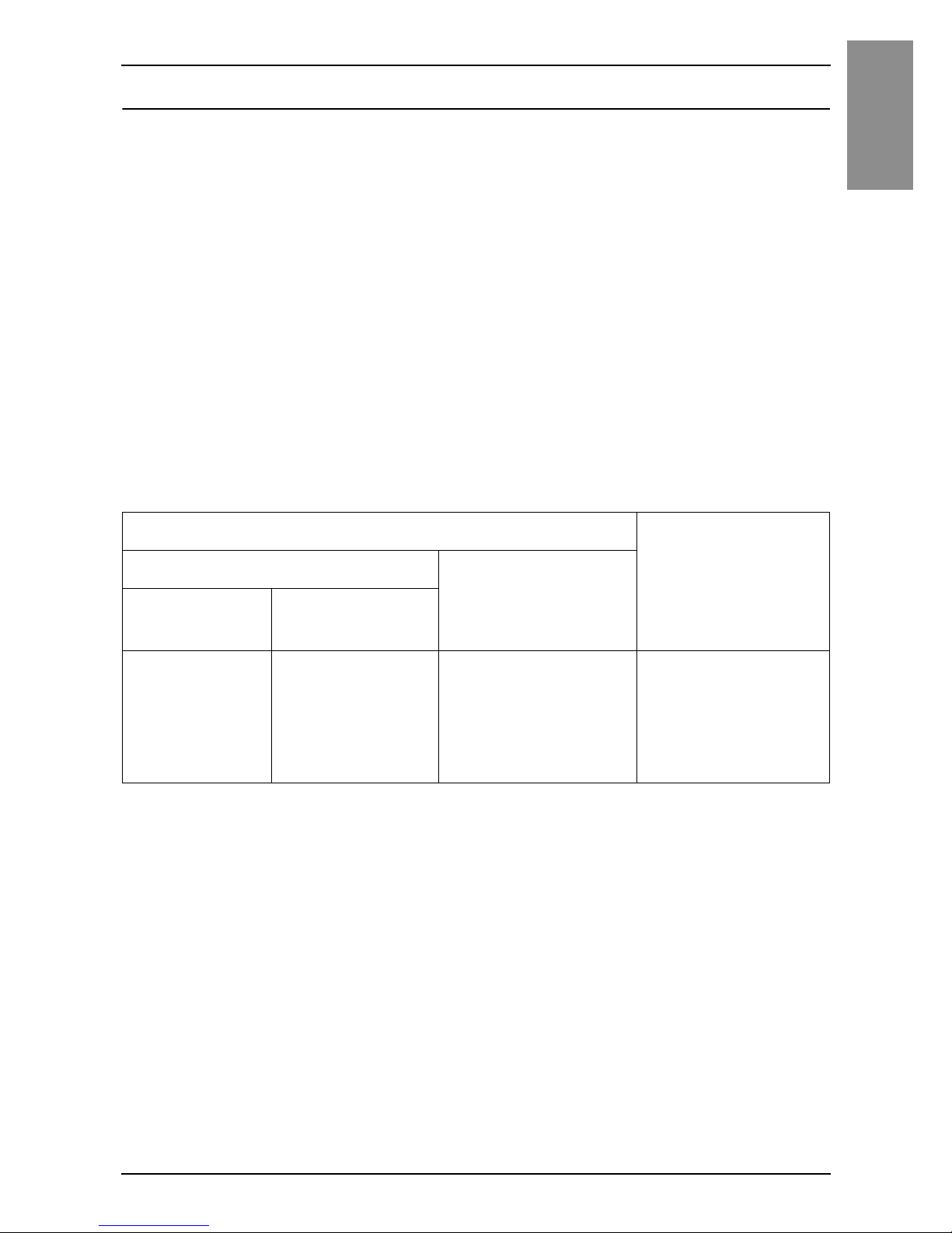
Panel Cut Dimensions
Based on the panel cut dimensions, open a mount hole on the panel.
Model name A B C
SP-5500TP
259 mm
(10.2 in)
201 mm
(7.91 in)
1.6... 5 mm
(0.06... 0.2 in)
SP-5600TP/
5660TP
301.5 mm
(11.87 in)
227.5 mm
(8.96 in)
SP-5700TP
383.5 mm
(15.1 in)
282.5 mm
(11.12 in)
SP-5400WA
190 mm
(7.48 in)
135 mm
(5.31 in)
SP-5500WA
255 mm
(10.04 in)
185 mm
(7.28 in)
SP-5600WA
295 mm
(11.61 in)
217 mm
(8.54 in)
+1-0+0.04
-0
+1
-0
+0.04
-0+1-0
+0.04
-0+1-0
+0.04
-0+1-0
+0.04
-0+1-0
+0.04
-0+1-0
+0.04
-0+1-0
+0.04
-0+1-0
+0.04
-0+1-0
+0.04
-0+1-0
+0.04
-0+1-0
+0.04
-0
Page 20
21
Installation
English
Installation Requirements
This product is designed for use on flat surfaces of Type 1, Type 4X (Indoor
Use Only) or Type 13 Enclosure.
Mount this product in an enclosure that provides a clean, dry, robust and
controlled environment (IP65F
*1
, IP66F*1, IP67F*1, Type 1, Type 4X [Indoor
Use Only], or Type 13 Enclosure).
For Advanced Display, the front surface is IP66F
*1
, IP67F*1, Type 1, Type 4X
(Indoor Use Only) or Type 13 Enclosure.
For Premium Display, when using a factory-installed front USB cover (without
screw), the front surface is IP65F
*1
, IP67F*1 or Type 1 Enclosure. When using
a front USB cover (with screw
*2
) manufactured by Pro-face (Model Number
PFXZCDCVUS1), the front surface is IP66F
*1
, IP67F*1, Type 1, Type 4X
(Indoor Use Only) or Type 13 Enclosure.
For Premium Display, regardless of using a factory-installed front USB cover
or a front USB cover with screw, when the cover is open, the front surface is
Type 1 Enclosure.
Be aware of the following when building this product into an end-use product:
• The rear face of this product is not approved as an enclosure. When building this
product into an end-use product, be sure to use an enclosure that satisfies
standards as the end-use product’s overall enclosure.
• Install this product in an enclosure with mechanical rigidity.
• This product is not designed for outdoor use. UL certification obtained is for
indoor use only.
• Install and operate this product with its front panel facing outward.
*1 IP65F, IP66F and IP67F
are not part of the UL certification.
*2 The necessary torque is 0.5 N•m (4.4 lb-in).
Display front surface Enclosure front
surface
Premium Display Advanced Display
Without
screw
With screw
IP65F, IP67F,
Type 1
IP66F, IP67F,
Type 1, Type 4X
(Indoor Use
Only), Type 13
IP66F, IP67F,
Type 1, Type 4X
(Indoor Use Only),
Type 13
IP65F, IP66F,
IP67F,
Type 1, Type 4X
(Indoor Use Only),
Type 13
Page 21
22
English
Installation
CAUTION
RISK OF BURNING INJURY
Do not touch the rear chassis during operation.
Failure to follow these instructions can result in injury or equipment
damage.
Check that the installation wall or cabinet surface is flat, in good condition
and has no jagged edges. Metal reinforcing strips may be attached to the
inside of the wall, near the panel-cut, to increase its rigidity.
Decide on the thickness of the enclosure wall, based on the level of strength
required: 1.6...5 mm (0.06...0.2 in).
Even if the installation wall thickness is within the recommended range for
the panel cut dimensions, depending on wall’s material, size, and installation
location of this product and other devices, the installation wall could warp. To
prevent warping, the installation surface may need to be strengthened.
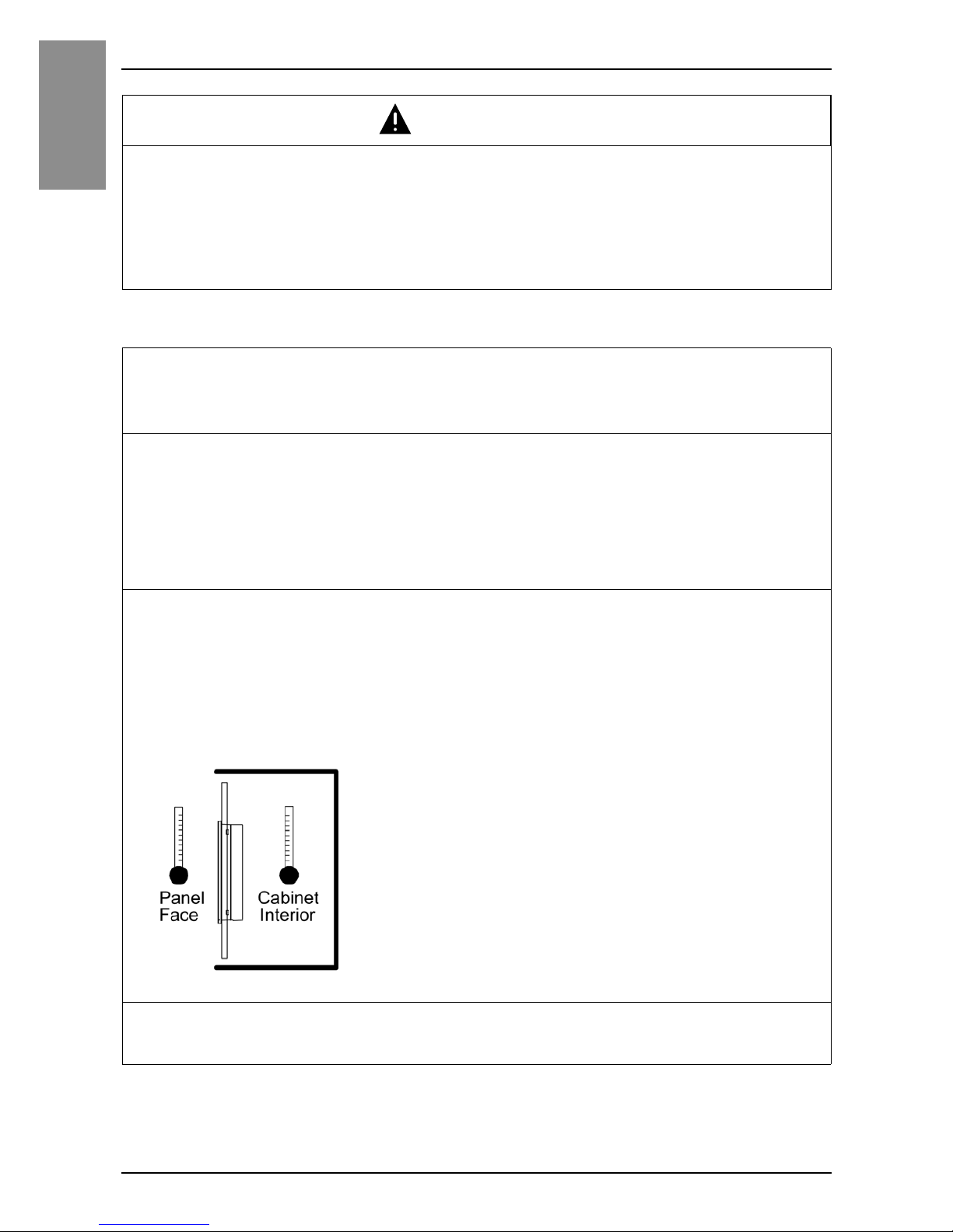
Be sure that the surrounding air temperature and the ambient humidity are
within their designated ranges. Surrounding air temperature: 0 to 60 °C (32
to 140 °F) (see the Environment Specifications for this product); ambient
humidity: 10 to 90% RH; wet bulb temperature: maximum 39 °C (102 °F).
When installing this product in a cabinet or enclosure, the surrounding air
temperature is the cabinet’s or enclosure’s internal temperature.
Be sure that heat from surrounding equipment does not cause this product
to exceed its standard operating temperature.
Page 22
23
Installation
English
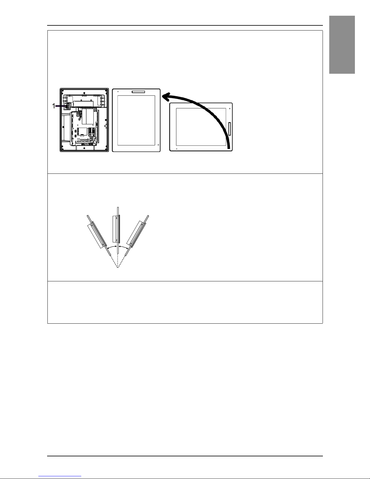
When mounting this product vertically, ensure that the right side of this
product faces up. In other words, the DC power connector should be at the
top.
NOTE: For vertical mounting, make sure your screen editing software supports the
function.
1 Power connector
When installing this product in a slanted position, the product face should
not incline more than 30°.
When installing this product in a slanted position with an incline more than
30°, the ambient temperature must not exceed 40 °C (104 °F). You may
need to use forced air cooling (fan, A/C) to ensure the ambient operating
temperature is 40 °C or less (104 °F or less).
30° or less
Page 23
24
English
Installation
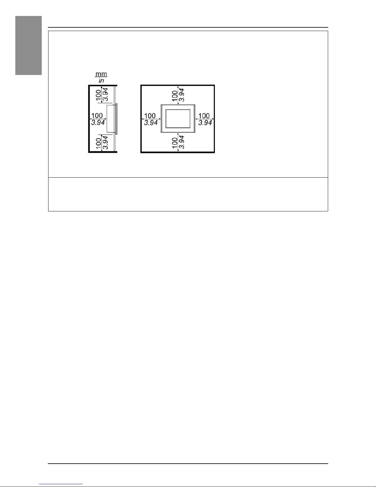
For easier maintenance, operation and improved ventilation, install this
product at least 100 mm (3.94 in) away from adjacent structures and other
equipment as shown in the following illustration:
Please ensure you have enough space to insert and remove the storage
card.
For Wireless LAN models, do not block the wireless LAN antenna area with
your hand, body or other objects. It may cause interference in wireless LAN
communications.
Page 24
25
Installation
English
Wireless LAN Models
2.4 GHz Wireless Devices
The Wireless LAN model uses the 2.4 GHz frequency range, which is used by
a wide range of wireless equipment. Example usage includes industrial,
scientific, and medical equipment such as microwave ovens, on-site wireless
stations (requiring licenses), low-power wireless stations (not requiring
licenses) as well as amateur wireless stations (requiring licenses).
1. Before use, confirm that no on-site wireless stations and specified low-
power wireless stations or amateur wireless stations operate in your
vicinity.
2. In the event that the Wireless LAN model causes harmful interference to
any other "on-site wireless stations", immediately change the channel
frequency of the Wireless LAN model, or change its location, or halt
operation of radio emissions and contact the administrator of the wireless
network to resolve the issue.
Security on Your Wireless LAN
Because wireless LANs do not normally provide adequate data security, the
following problems may occur.
1. Unlawful access of communication information.
• There is a chance that information found in emails, and personal information
such as user IDs, passwords, and credit card numbers, may be intentionally
intercepted by a malicious third party.
2. Illegal access
A malicious third party may be able to access personal or company data
over the company's local area network without permission, to:
• Obtain personal and confidential information (information leak)
• Impersonate someone by communicating as that person and disseminating
invalid information (spoofing)
WARNING
ELECTROMAGNETIC/RADIO INTERFERENCE
If you are uncertain of the policy that applies to the use of the Wireless LAN
model, ask the administrator about its use before you turn it on.
Failure to follow these instructions can result in death, serious injury,
or equipment damage.
Page 25

26
English
Installation
• Alter intercepted communications and re-transmitting tolerated content
(falsification)
• Cause critical damage to data and or systems due to a computer virus
(damage).
This wireless LAN product includes security features that enable you to
configure security-related settings that reduce the likelihood of the abovementioned problems.
We recommend that you make yourself fully acquainted with the possible
implications of what might happen if you use a wireless product without
enabling security features, and that you configure security-related settings and
use wireless products at your own responsibility.
Page 26
27
Installation
English
Installation Procedure
Installing to the Panel
DANGER
HAZARD OF ELECTRIC SHOCK, EXPLOSION OR ARC FLASH
• Remove all power from the device before removing any covers or elements
of the system, and prior to installing or removing any accessories,
hardware, or cables.
• Unplug the power cable from both the Display Module and the power
supply.
• Always use a properly rated voltage sensing device to confirm power is off.
• Replace and secure all covers or elements of the system before applying
power to the Display Module.
Failure to follow these instructions will result in death or serious injury.
NOTICE
EQUIPMENT DAMAGE
• When mounting this product vertically, first install the Box Module onto the
Display Module before attaching the Display Module to the panel.
• Keep this product stabilized in the panel-cut while you are installing or
removing the screw fasteners.
Failure to follow these instructions can result in equipment damage.
Step Action
1 When mounting this product vertically, place the Display Module
on a clean and level surface with the screen facing down and
mount the Box Module to the Display Module.
NOTE: Refer to the SP5000 Series Hardware Manual or SP5000 Series
(Box Module) Installation Guide on how to mount the Box Module to the
Display Module.
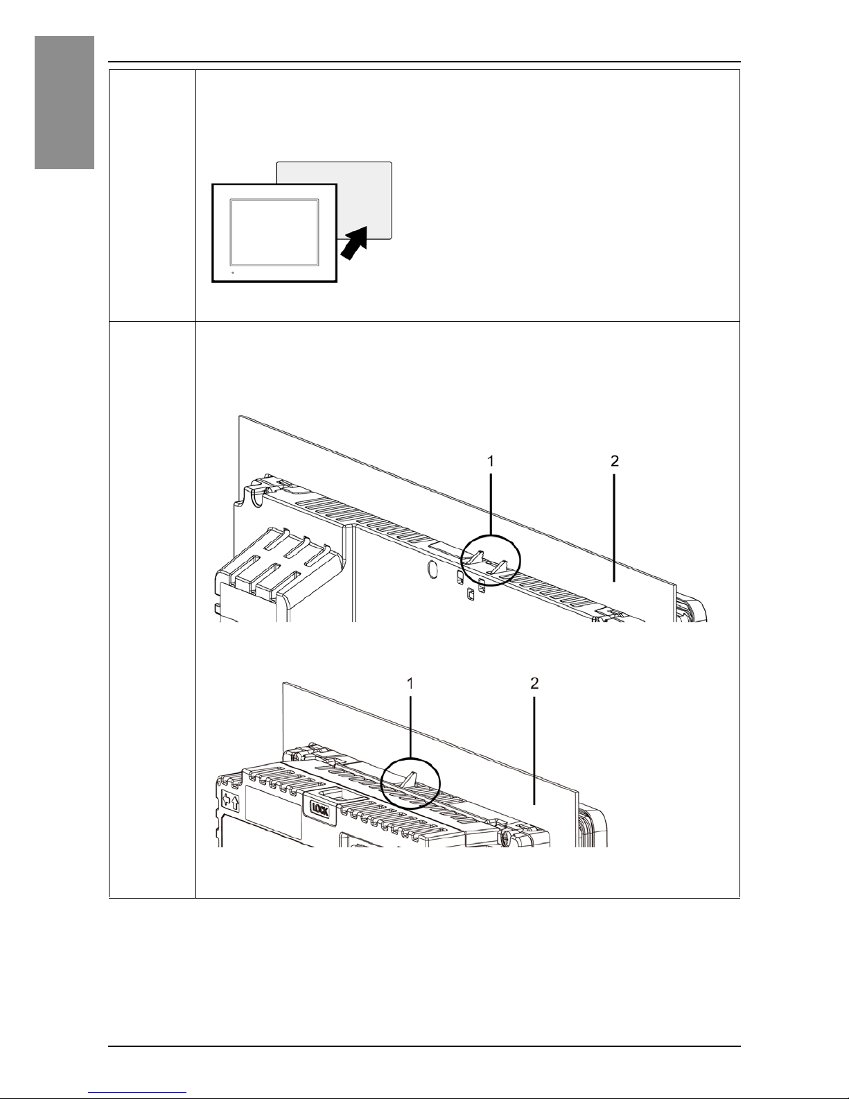
2 Check that the Display Module’s gasket is seated securely into
the bezel’s groove, which runs around the perimeter of the
display panel frame.
NOTE: Always use the installation gasket, since it absorbs vibration in
addition to repelling water. For the procedure on replacing the installation
gasket, refer to SP5000 Series Hardware Manual.
Page 27
28
English
Installation
3 Based on the Display Module’s panel cut dimensions (see
page 20), open a mount-hole on the panel and attach the Display
Module to the panel from the front side.
4 Confirm that the anti-drop lock on the top of the Display Module is
attached to the panel.
Except for SP-5400WA
SP-5400WA
1 Anti-drop lock
2 Panel
Page 28
29
Installation
English
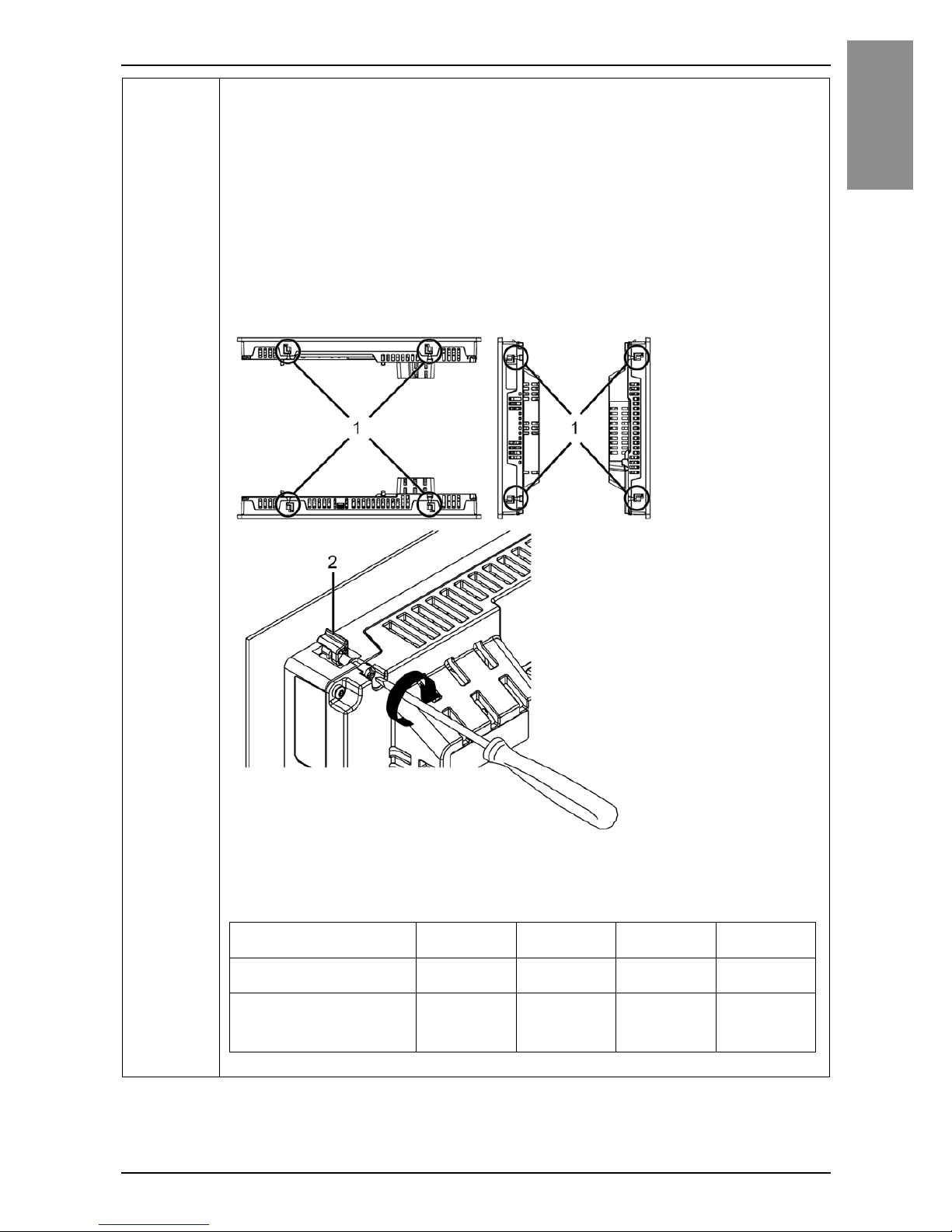
5 Using a Phillips screwdriver, gradually tighten (turn clockwise) the
screws for the fasteners (top, bottom, left, and right), alternating
diagonally between screws until all are secure. Be sure that the Lshaped part of the installation fastener (2 in figure below) is
completely vertical. The necessary torque is 0.5 N•m (4.4 lb-in).
NOTE:
• If the Display Module is not mounted properly, it may fall.
• If the panel is thick (approx. 5 mm [0.2 in]), you may have trouble straightening
the L-shaped part of the installation fastener. If this happens, push the Display
Module from the front as you tighten the screws.
1 Installation fastener
2 L-shaped part of the Installation fastener
Number of Installation Fasteners
Top Bottom Right Left
15-inch models2222
Models less than
12-inch
22––
Page 29

30
English
Installation
NOTICE
BROKEN ENCLOSURE
Do not exert more than 0.5 N•m (4.4 lb-in) of torque when tightening the
fastener’s screws.
Failure to follow these instructions can result in equipment damage.
Page 30
31
Installation
English
Removal Procedure
Removing from the Panel
DANGER
HAZARD OF ELECTRIC SHOCK, EXPLOSION OR ARC FLASH
• Remove all power from the device before removing any covers or elements
of the system, and prior to installing or removing any accessories,
hardware, or cables.
• Unplug the power cable from both the Display Module and the power
supply.
• Always use a properly rated voltage sensing device to confirm power is off.
• Replace and secure all covers or elements of the system before applying
power to this product.
Failure to follow these instructions will result in death or serious injury.
NOTICE
EQUIPMENT DAMAGE
• When this product is mounted vertically, first remove the Display Module
from the panel, then remove the Box Module from the Display Module.
• Keep this product stablized in the panel-cut while you are installing or
removing the screw fasteners.
Failure to follow these instructions can result in equipment damage.
Page 31
32
English
Installation
Step Action
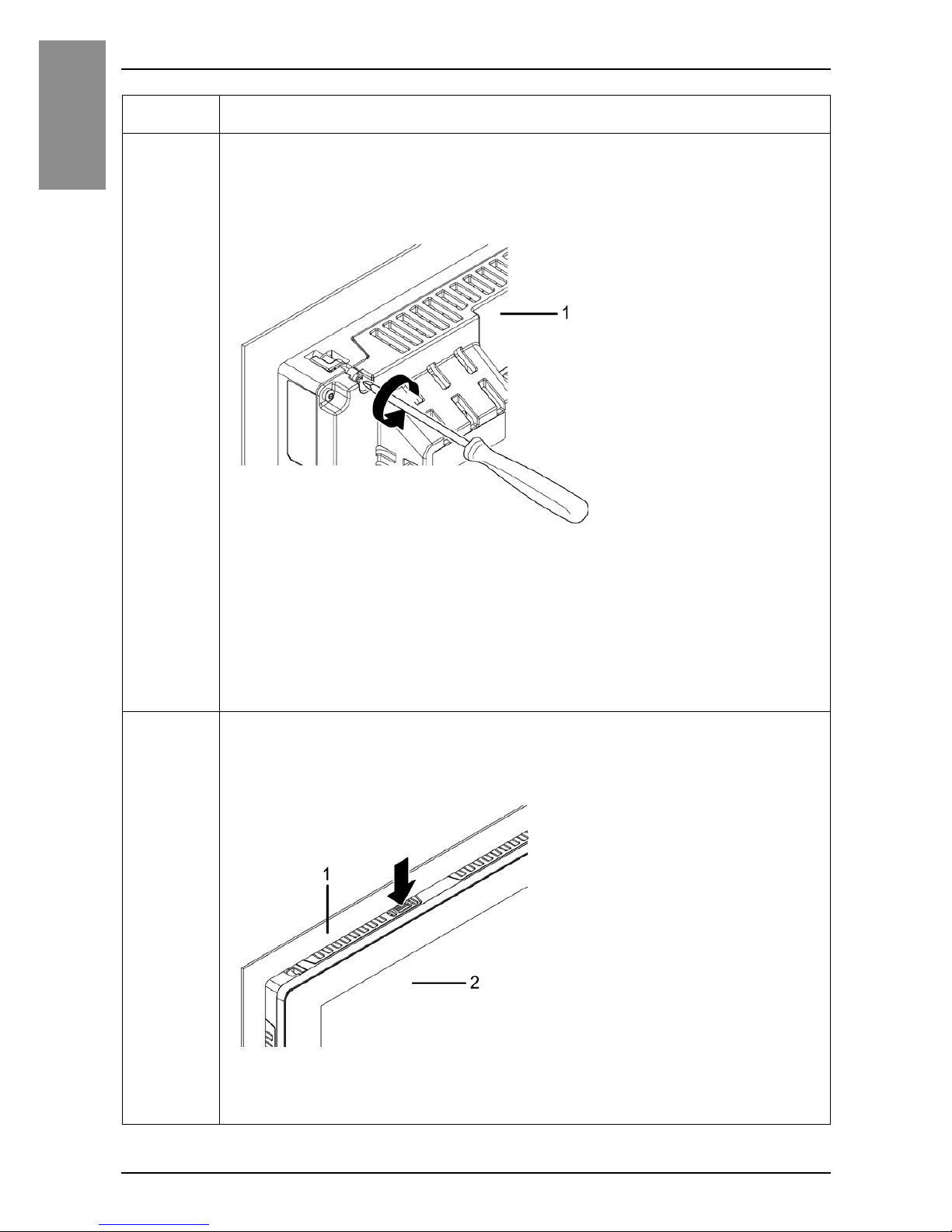
1 Using a Phillips screwdriver, gradually loosen (turn
counterclockwise) the screws for the fasteners (top, bottom, left,
and right), alternating diagonally between screws until all screws
are loose.
1 Rear side
NOTE:
• For the number of installation fasteners on your model, see Number of
Installation Fasteners in Step 5 of Installing to the Panel (see page 29).
• If the panel is thick (approx. 5 mm [0.2 in]), you may have trouble straightening
the L-shaped part of the installation fastener. If this happens, push the display
module from the front as you loosen the screws.
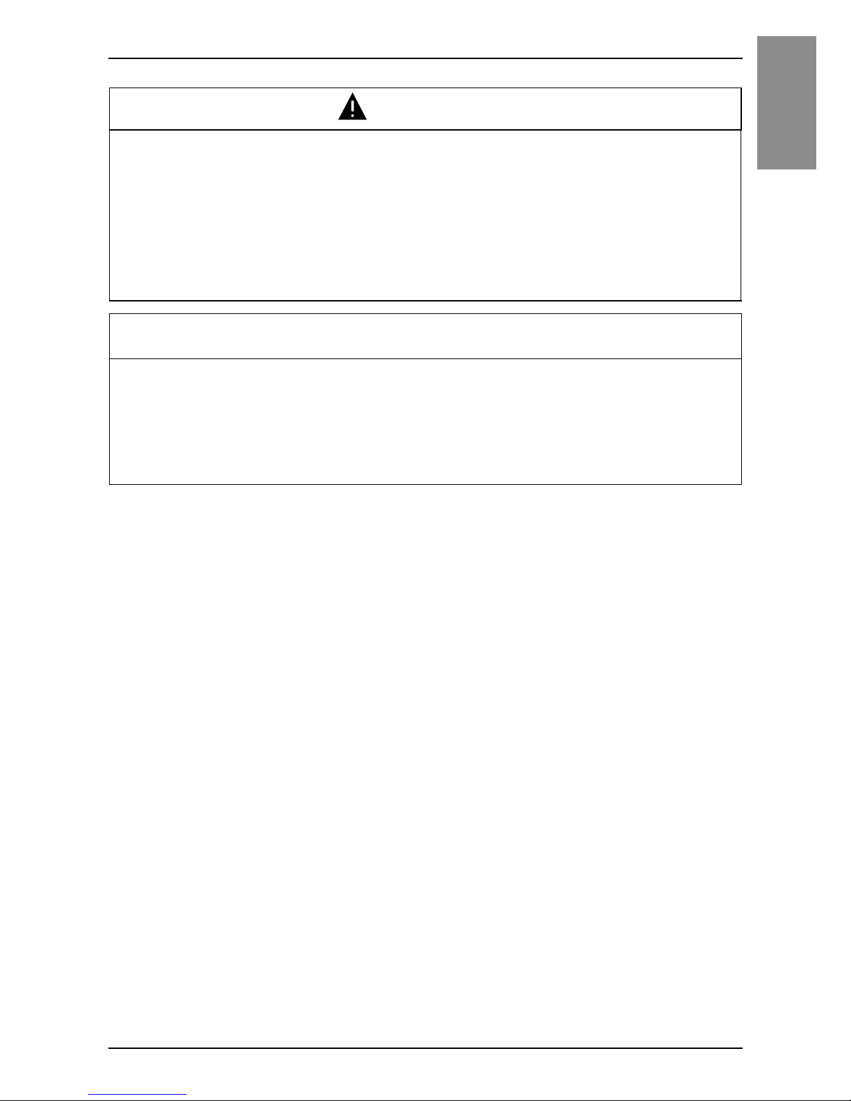
2 While pushing on the anti-drop lock on the top of the Display
Module with a tool such as a screwdriver, slowly remove the
Display Module from the panel.
1 Panel
2 Front side
Page 32
33
Installation
English
CAUTION
RISK OF INJURY
Do not drop this product when you remove it from the panel.
• Hold this product in place after removing the fasteners.
• Use both hands.
• While pushing on the anti-drop lock, be careful not to hurt your fingers.
Failure to follow these instructions can result in injury or equipment
damage.
NOTICE
EQUIPMENT DAMAGE
To avoid damage, remove this product while pushing the anti-drop lock or by
making sure the lock does not touch the panel.
Failure to follow these instructions can result in equipment damage.
Page 33
34
English
Wiring
Wiring
NOTE:
• The SG (signal ground) and FG (functional ground) terminals are connected internally in this
product.
• When the FG terminal is connected, be sure the wire is grounded. Not grounding this product
can result in excessive electromagnetic interference (EMI).
DANGER
HAZARD OF ELECTRIC SHOCK, EXPLOSION OR ARC FLASH
• Remove all power from the device before removing any covers or elements
of the system, and prior to installing or removing any accessories,
hardware, or cables.
• Remove power before wiring this product’s power terminals.
• Always use a properly rated voltage sensing device to confirm power is off.
• Replace and secure all covers or elements of the system before applying
power to this product.
• This product uses only 12 to 24 Vdc power. Using any other level of power
can damage both the power supply and this product.
• Since this product is not equipped with a power switch, be sure to connect
a power switch to the power supply.
• Be sure to ground this product’s FG terminal.
Failure to follow these instructions will result in death or serious injury.
Page 34
35
Wiring
English
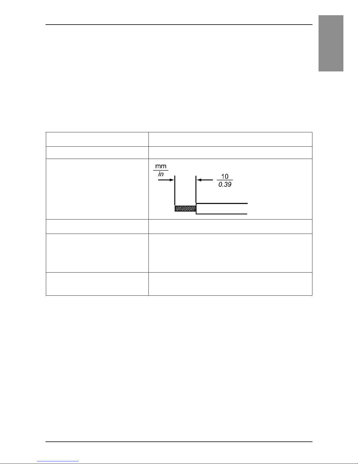
DC Power Cord Preparation
• Make sure the ground wire is either the same or heavier gauge than the power
wires.
• Do not use aluminum wires in the power supply’s power cord.
• To prevent the possibility of a terminal short, use a pin terminal that has an
insulating sleeve.
• If the ends of the individual wires are not twisted correctly, the wires may create
a short circuit.
• The conductor type is solid or stranded wire.
• Use copper wire rated for 75 °C (167°F).
*1 For UL compatibility, use AWG 14 or AWG 13.
*2 Items are made by Phoenix Contact.
Power cord diameter
0.75...2.5 mm
2
(18...13 AWG)
*1
Conductor type Solid or stranded wire
Conductor length
Recommended driver
*2
SZS 0.6 x 3.5 (1205053)
Recommended pin
terminals
*2
3201288 AI 0,75 - 10 GY
3200182 AI 1 - 10 RD
3200195 AI 1,5 - 10 BK
3202533 AI 2,5 - 10 BU
Recommended pin terminal
crimp tool
*2
CRIMPFOX6
Page 35
36
English
Wiring
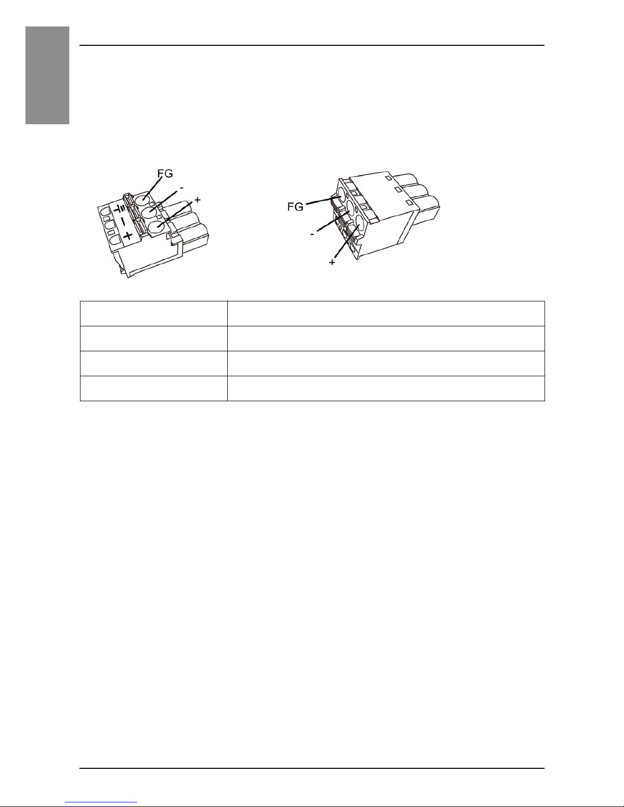
Power Connector Specifications: Spring Clamp Terminal
Blocks
Models except for SP-5400WA come with the right-angle type power connector,
and the SP-5400WA comes with the straight type power connector.
NOTE:
• You cannot connect the right-angle type to the SP-5400WA.
• Right-angle type: PFXZCBCNDC2 manufactured by Pro-face
Straight type: PFXZCBCNDC1 manufactured by Pro-face
Connection Wire
+ 12...24 Vdc
–0Vdc
FG Grounded terminal connected to the panel chassis.
Right-angle type Straight type
Page 36
37
Wiring
English
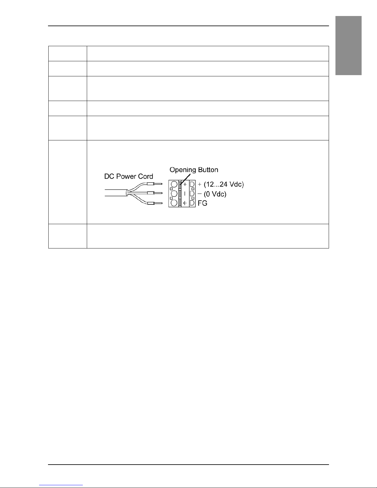
How to Connect the DC Power Cord
NOTE: Do not solder the wire directly to the power crimp pin
Step Action
1 Confirm the power cord is not connected to the power supply.
2 Check the rated voltage, and remove the “DC24V” sticker on the
DC power supply connector.
3 Connect each wire from the power cable to a pin terminal.
4 Push the Opening button with a small and flat screwdriver to open
the desired pin hole.
5 Insert each power cord wire into its corresponding holder.
Release the Opening button to clamp the wire in place.
When using stranded wire, do not short with neighboring wires.
6 After inserting all three power cord wires, insert the DC power
supply connector into the power connector on this product.
Page 37
38
English
Wiring
Wiring Precautions
Improving Noise/Surge Resistance
• This product’s power supply cord should not be bundled with or kept close to
main circuit lines (high voltage, high current), power lines, or input/output lines,
and their various systems should be kept separate. When power lines cannot be
wired via a separate system, use shielded cables for input/output lines.
• Make the power cord as short as possible, and be sure to twist the ends of the
wires together (i.e. twisted pair cabling) from close to the power supply unit.
• If there is an excess amount of noise on the power supply line, connect a noise
reducing transistor before turning on the power.
• Connect a surge protection device to handle power surges.
• To increase noise resistance, attach a ferrite core to the power cable.
DANGER
SHORT CIRCUIT, FIRE, OR UNINTENDED EQUIPMENT
OPERATION
Avoid excessive force on the power cable to prevent accidental
disconnection
• Securely attach power cables to an installation panel or cabinet.
• Install and fasten this product on installation panel or cabinet prior to
connecting power supply and communication lines.
Failure to follow these instructions will result in death or serious injury.
Page 38
39
Wiring
English
Power Supply Connections
• Branch Circuit Protective device shall be used for rating 20 A for 12 to 24 Vdc
input device on the models except for SP-5400WA.
• You must use DC input with an isolating source for the models except for
SP-5400WA.
• You must use DC input with a Class 2 power supply for SP-5400WA.
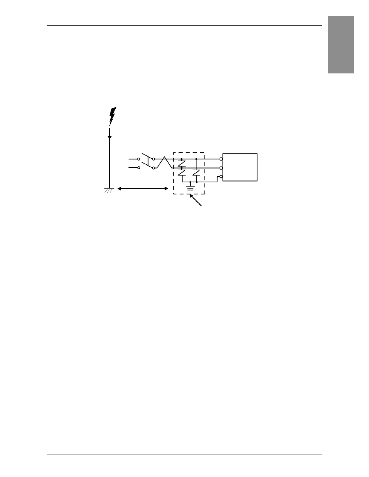
• The following shows a surge protection device connection:
Attach a surge protection device to prevent damage to this product as a result of
a lightning-induced power surge from a large electromagnetic field generated
from a direct lightning strike. We also strongly recommend to connect the
crossover grounding wire of this product to a position close to the ground
terminal of the surge protection device.
It is expected that there will be an effect on this product due to fluctuations in
grounding potential when there is a large surge flow of electrical energy to the
lightning rod ground at the time of a lightning strike. Provide adequate distance
between the lightning rod grounding point and the surge protection device
grounding point.
Surge protection device
FG
This product
Lightning
Lightning rod
Ground
Provide adequate
distance.
Page 39
40
English
Wiring
Grounding
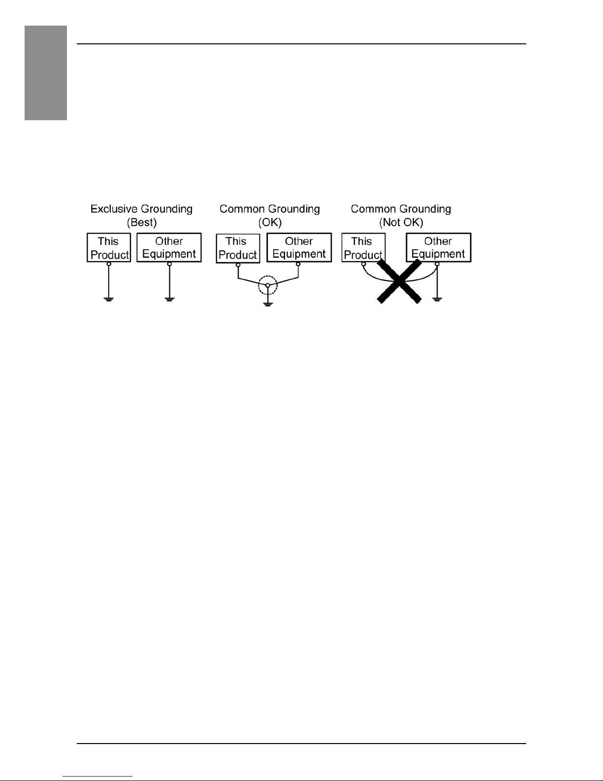
• Check that the grounding resistance is 100 Ω or less.
*1
• The FG wire should have a cross sectional area greater than 2 mm2 (AWG14)*1.
Create the connection point as close to this product as possible, and make the
wire as short as possible. When using a long grounding wire, replace the thin
wire with a thicker wire, and place it in a duct.
*1 Observe local codes and standards.
Short Circuit Prevention
• The SG (signal ground) and FG (functional ground) terminals are connected
internally in this product. When connecting the SG line to another device, be sure
that no shorting loops are formed.
Page 40
41
English
Front USB Cover
Front USB Cover
For Premium Display, when using a factory-installed front USB cover (without
screw), the front surface is IP65F
*1
, IP67F*1 or Type 1 Enclosure. When using
a front USB cover (with screw
*2
) manufactured by Pro-face (Model Number
PFXZCDCVUS1), the front surface is IP66F
*1
, IP67F*1, Type 1, Type 4X
(Indoor Use Only) or Type 13 Enclosure.
NOTE: Advanced Display does not have a front USB port.
Regardless of using a factory-installed front USB cover or a front USB cover
with screw, when the cover is open, the front surface is Type 1 Enclosure.
*1 IP65F, IP66F and IP67F are not part of the UL certification.
*2 The necessary torque is 0.5 N•m (4.4 lb-in).
CAUTION
RISK OF INJURY
When opening the front USB cover, be careful not to injure your fingers.
Failure to follow these instructions can result in injury or equipment
damage.
Step Action
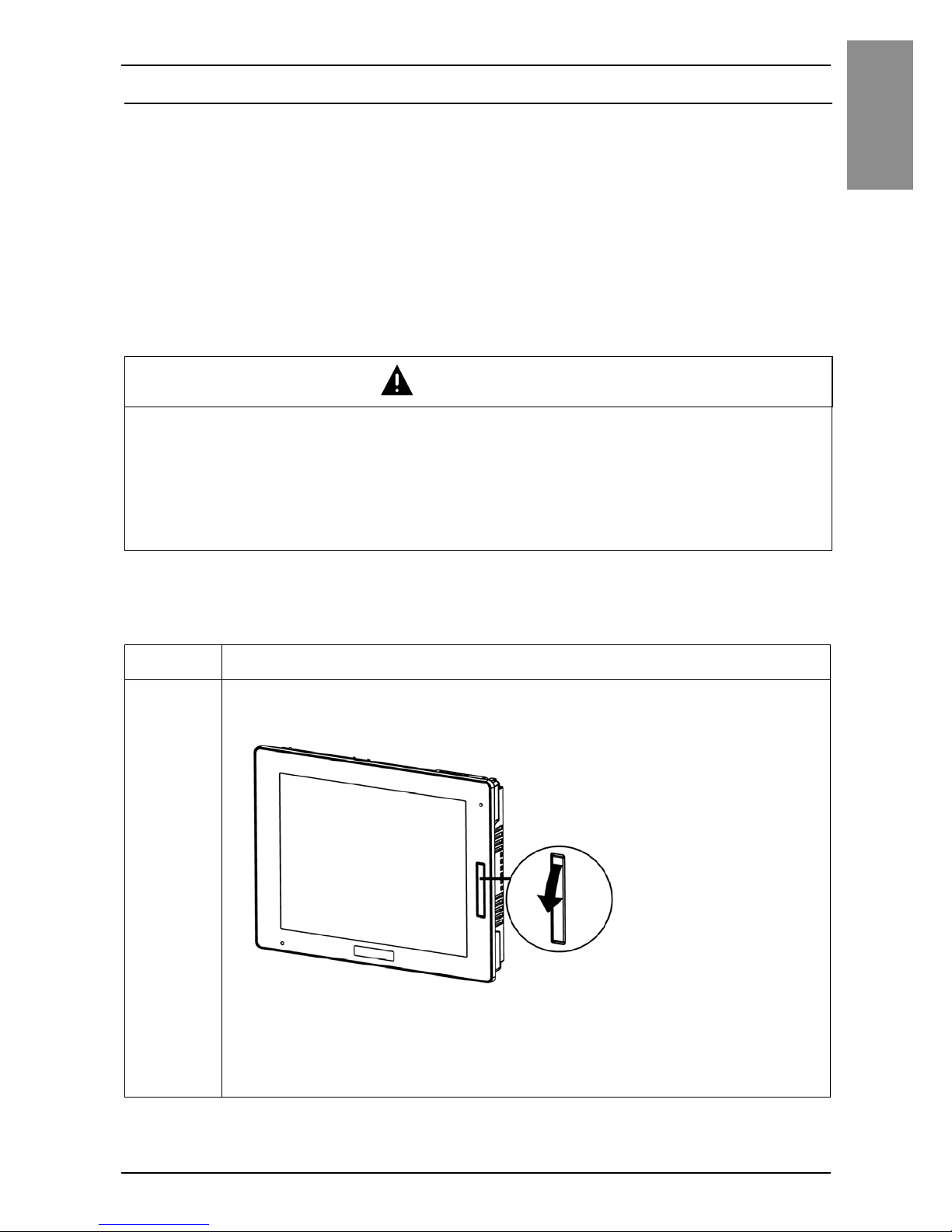
1 Place your finger or a tool such as a screwdriver in the gap on the
top of the front USB cover and pull down as illustrated.
NOTE:
• When using the front USB cover manufactured by Pro-face (Model Number
PFXZCDCVUS1), loosen the top screw using a Phillips screwdriver.
• The necessary torque is 0.5 N•m (4.4 lb-in).
Page 41
42
English
Front USB Cover
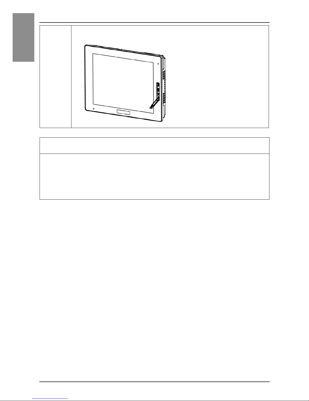
2 The USB interface can be seen once you pull down the front USB
cover.
NOTICE
BROKEN ENCLOSURE
Do not exert more than 0.5 N•m (4.4 lb-in) of torque when tightening the
screw.
Failure to follow these instructions can result in equipment damage.
Page 42
43
English
Front USB Port
Front USB Port
USB Connections
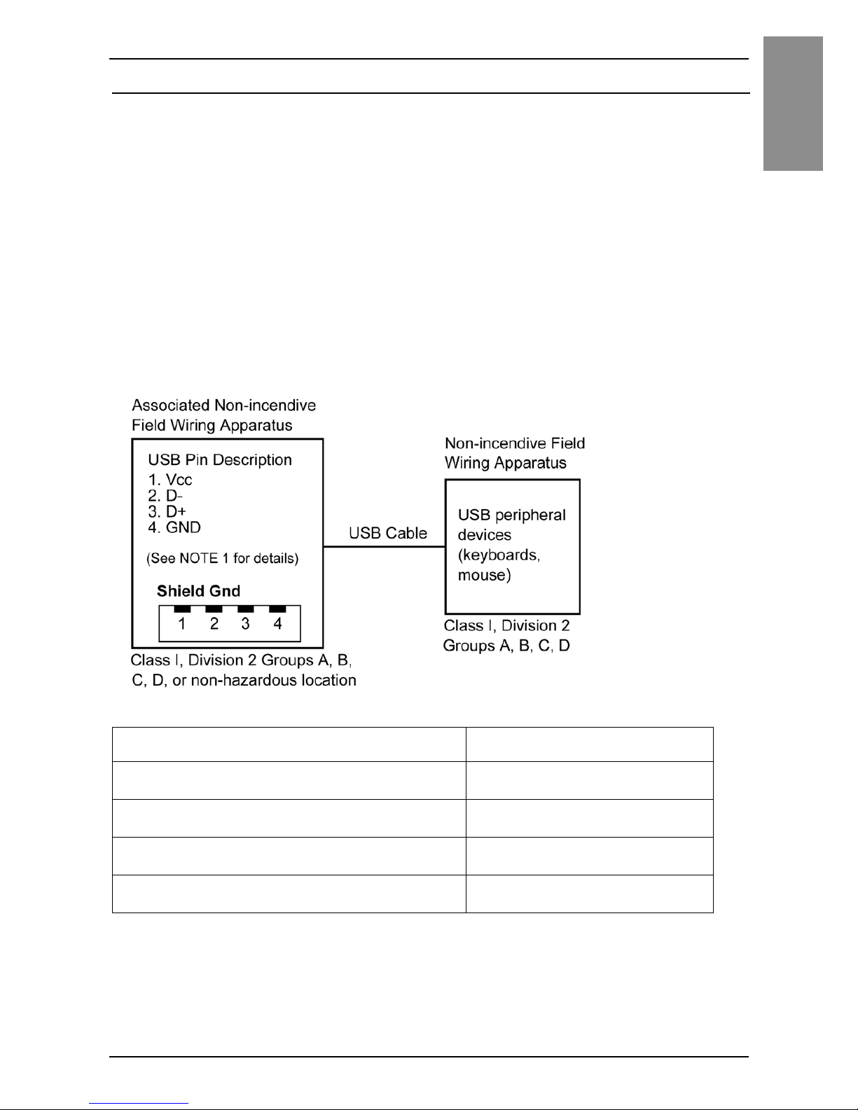
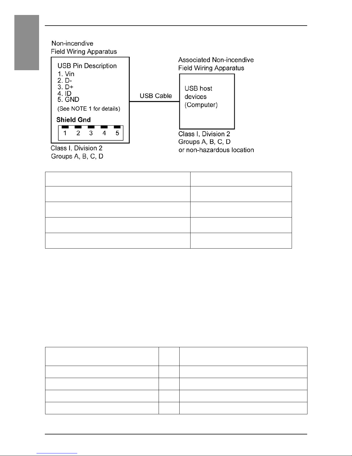
Non-incendive field wiring apparatus (keyboards, mouse) are permitted for use
on front USB port (Type A) of associated field wiring non-incendive Apparatus
(this product). Non-incendive field wiring apparatus (this product) are
permitted for use on front USB port (mini-B) of associated field wiring nonincendive apparatus (Computer)
In addition to being non-incendive, any equipment connected to the front USB
ports must satisfy the following criteria.
The following figures show the USB cable wiring:
<Type A>
Circuit parameters Front USB (Type A)
Open-circuit voltage = V
oc
5.25 Vdc
Short-circuit current = I
sc
1300 mA
Associated capacitance = C
a
265 μF
Associated inductance = L
a
16 μH
Page 43
44
English
Front USB Port
<mini-B>
NOTE:
1. The above tables list the Non-incendive Circuit Parameters.
The Entity Concept allows interconnection of non-incendive apparatus with associated
apparatus – not specifically examined combinations – as a system when the approved
values of Voc (or Uo) and Isc (or Io) for the associated apparatus are less than or equal to
Vmax (Ui) and Imax (Ii) for the non-incendive apparatus, and the approved values of Ca
(Co) and La (Lo) for the associated apparatus are greater than or equal to Ci + C
cable
and Li
+ L
cable
, respectively, for the non-incendive field wiring apparatus.
2. Associated non-incendive field wiring apparatus and non-incendive field wiring apparatus
shall satisfy the following:
Circuit parameters Front USB (mini-B)
Maximum input voltage = V
max
5.25 Vdc
Maximum load current = I
max
0.1 mA
Internal capacitance = C
i
0.24 μF
Internal inductance = L
i
16 μH
Associated non-incendive field
wiring apparatus
– Non-incendive field wiring apparatus
V
oc
≤ V
max
I
sc
≤ I
max
C
a
≥ Ci + C
cable
L
a
≥ Li + L
cable
Page 44
45
Front USB Port
English
3. If the electrical parameters of the cable are unknown, the following values may be used:
C
cable
= 196.85 pF/m (60 pF/ft)
L
cable
=0.656μH/m (0.20 μH/ft)
4. Wiring methods must be in accordance with the electrical code of the country where it is
used.
This product must be installed in an enclosure. If installed in a Class I,
Division 2 Location, the enclosure must be capable of accepting one or more
Division 2 wiring methods.
DANGER
POTENTIAL FOR EXPLOSION
• Verify that the power, input and output (I/O) wiring are in accordance with
Class I, Division 2 wiring methods.
• Substitution of any component may impair suitability for Class I, Division 2.
• Do not disconnect equipment while the circuit is live or unless the area is
known to be free of ignitable concentrations.
• Remove power before attaching or detaching any connectors to or from this
product.
• Ensure that power, communication, and accessory connections do not place
excessive stress on the ports. Consider the vibration in the environment when
making this determination.
• Securely attach power, communication, and external accessory cables to the
panel or cabinet.
• Use only commercially available USB cables.
• Use only non-incendive USB configurations.
• The associated non-incendive field wiring apparatus shall not be connected in
parallel unless approved by the associated non-incendive apparatus.
• This product is suitable for use and provides non-incendive field wiring to
apparatus in Class I, Division 2, Groups A, B, C, D Hazardous Locations.
Failure to follow these instructions will result in death or serious injury.
Page 45
46
English
Standards
Standards
For information on certifications and standards, such as certified models and
certificates, see the product markings or the following URL:
http://www.pro-face.com/trans/en/manual/1002.html
DANGER
POTENTIAL FOR EXPLOSION
• Suitable for use in Class I, Division 2, Groups A, B, C, and D Hazardous
Locations.
• Substitution of any component may impair suitability for Class I, Division 2.
• Do not disconnect equipment while the circuit is live or unless power the
area is known to be free of ignitable concentrations.
• Always confirm that this product is suitable for use in hazardous locations
by checking that the ANSI/ISA 12.12.01 and CSA C22.2 N°213 certification
appears on the product labeling.
• Do not attempt to install, operate, modify, maintain, service, or otherwise
alter this product except as permitted in this manual. Unpermitted actions
may impair the suitability of this product for Class I, Division 2 operation.
• To power on or power off this product installed in a Class I, Division 2
hazardous location, you must either:
• Use a switch located outside the hazardous environment, or
• Use a switch certified for Class I, Division 1 operation inside the hazardous
area.
• Do not disconnect equipment unless power has been switched off or the area
is known to be non-hazardous. This applies to all connections including power,
ground, serial, parallel, and network connections.
• Never use unshielded / ungrounded cables in hazardous locations.
• When enclosed, keep enclosure doors and openings closed at all times to
avoid the accumulation of foreign matter inside the workstation.
Failure to follow these instructions will result in death or serious injury.
Page 46
47
Standards
English
The following message is for UL Hazardous Locations.
DANGER
RISQUE D’EXPLOSION
• Le remplacement de n’importe quel composant peut nuire à la conformité à la
Classe I, Division 2.
• Avant de déconnecter l’équipement, couper le courant ou s’assurer que
l’emplacement est désigné non dangereux.
Le non-respect de ces instructions provoquera la mort ou des
blessures graves.
Inquiry
Do you have any questions about difficulties with your unit?
Please access our site any time that you need help with a solution.
http://www.pro-face.com/trans/en/manual/1001.html
Please be aware that Digital Electronics Corporation shall not be held liable
by the user for any damages, losses, or third party claims arising from the
uses of this product.
Note
Page 47

48
English
Page 48

49
WLAN
Wireless LAN Information
USA
SP-5660TP contains Transmitter Module FCC ID: N6C-SDMGN
FCC CAUTION
Changes or modifications not expressly approved by the party responsible for
compliance could void the user’s authority to operate the equipment.
NOTE: This equipment has been tested and found to comply with the limits for a Class A
digital device, pursuant to part 15 of the FCC Rules. These limits are designed to provide
reasonable protection against harmful interference when the equipment is operated in a
commercial environment. This equipment generates, uses, and can radiate radio frequency
energy and, if not installed and used in accordance with the instruction manual, may cause
harmful interference to radio communications. Operation of this equipment in a residential
area is likely to cause harmful interference in which case the user will be required to correct
the interference at his own expense.
This transmitter must not be co-located or operated in conjunction with any
other antenna or transmitter.
This equipment complies with FCC radiation exposure limits set forth for an
uncontrolled environment and meets the FCC radio frequency (RF) Exposure
Guidelines in Supplement C to OET65. This equipment should be installed
and operated keeping the radiator at least 20 cm or more away from person’s
body (excluding extremities: hands, wrists, feet and ankles).
Page 49

50
WLAN
Canada
SP-5660TP contains Transmitter Module IC: 4908B-SDMGN
This device complies with Industry Canada licence-exempt RSS standard(s).
Operation is subject to the following two conditions: (1) this device may not
cause interference, and (2) this device must accept any interference, including
interference that may cause undesired operation of the device.
Le présent appareil est conforme aux CNR d'Industrie Canada applicables aux
appareils radio exempts de licence. L'exploitation est autorisée aux deux
conditions suivantes : (1) l'appareil ne doit pas produire de brouillage, et (2)
l'utilisateur de l'appareil doit accepter tout brouillage radioélectrique subi,
même si le brouillage est susceptible d'en compromettre le fonctionnement.
This equipment complies with IC radiation exposure limits set forth for an
uncontrolled environment and meets RSS-102 of the IC radio frequency (RF)
Exposure rules. This equipment should be installed and operated keeping the
radiator at least 20cm or more away from person’s body (excluding
extremities: hands, wrists, feet and ankles).
Cet équipement est conforme aux limites d’exposition aux rayonnements
énoncées pour un environnement non contrôlé et respecte les règles
d’exposition aux fréquences radioélectriques (RF) CNR-102 de l’IC. Cet
équipement doit être installé et utilisé en gardant une distance de 20 cm ou
plus entre le dispositif rayonnant et le corps (à l’exception des extrémités :
mains, poignets, pieds et chevilles).
Page 50
51
WLAN
Europe
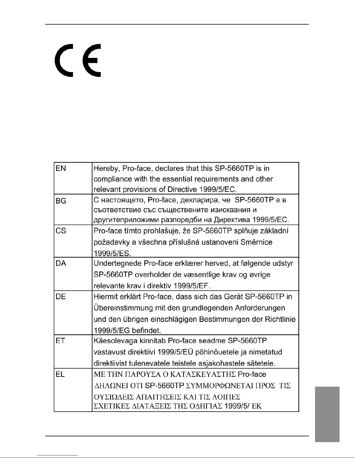
EN300 328, EN301 489, EN60950-1
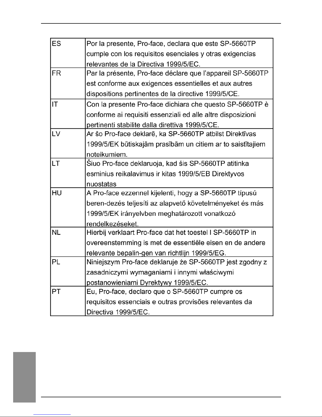
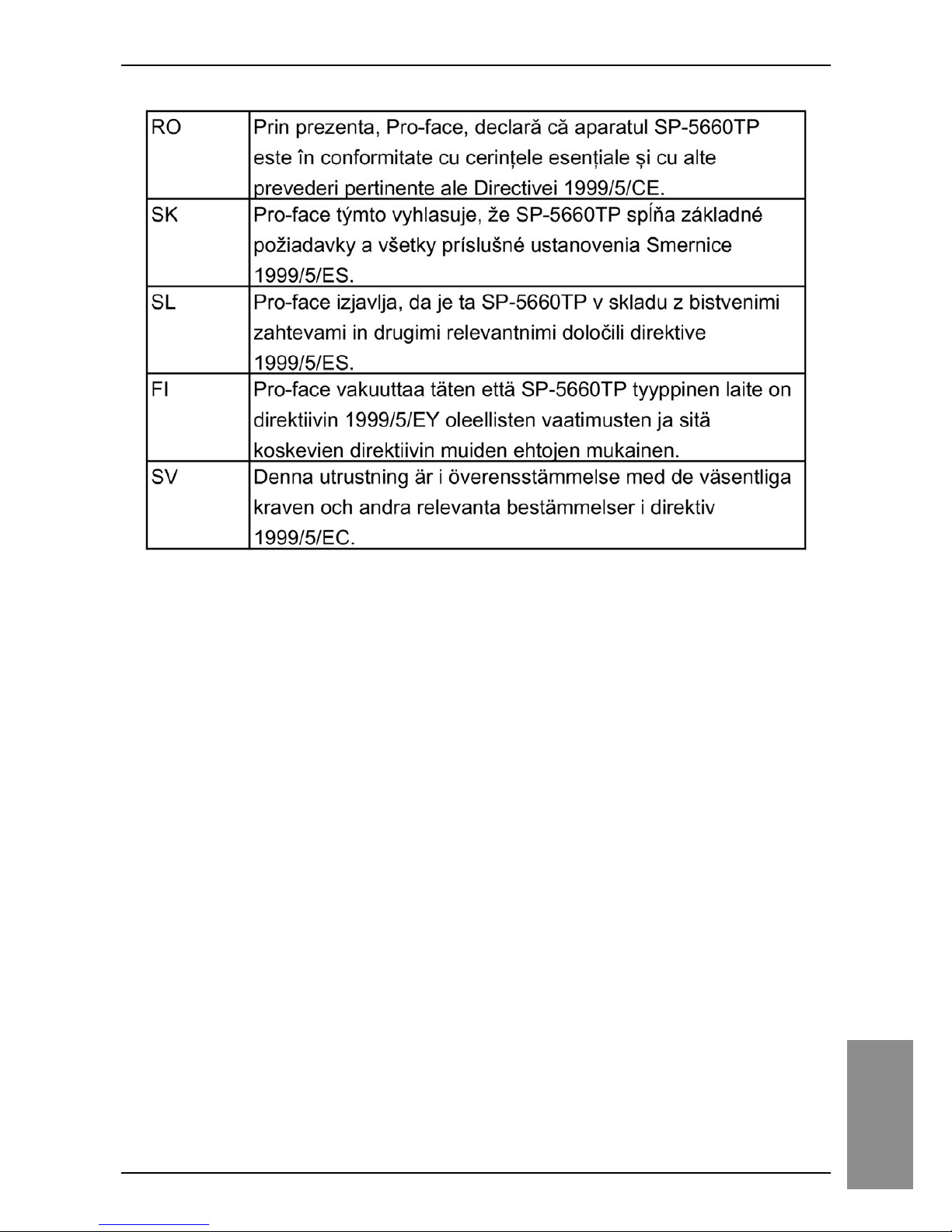
SP-5660TP may be operated in Belgium, Bulgaria, Czech Republic,
Denmark, Germany, Estonia, Greece, Spain, France, Ireland, Italy, Cyprus,
Latvia, Lithuania, Luxembourg, Malta, Hungary, Netherlands, Austria, Poland,
Portugal, Romania, Slovak Republic, Slovenia, Finland, Sweden, United
Kingdom.
Page 51
52
WLAN
Page 52
53
WLAN
Page 53
54
WLAN
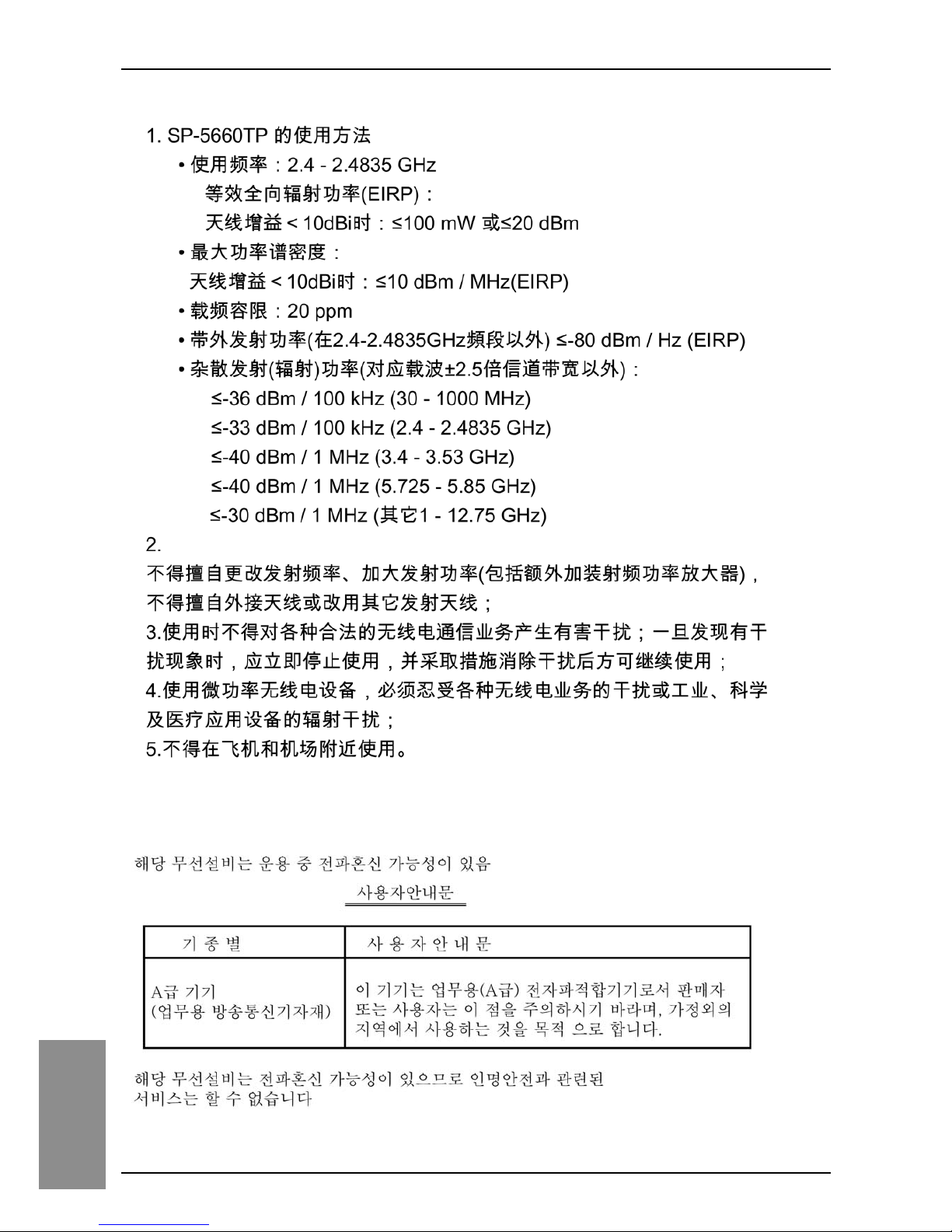
China
Korea
Page 54
55
WLAN
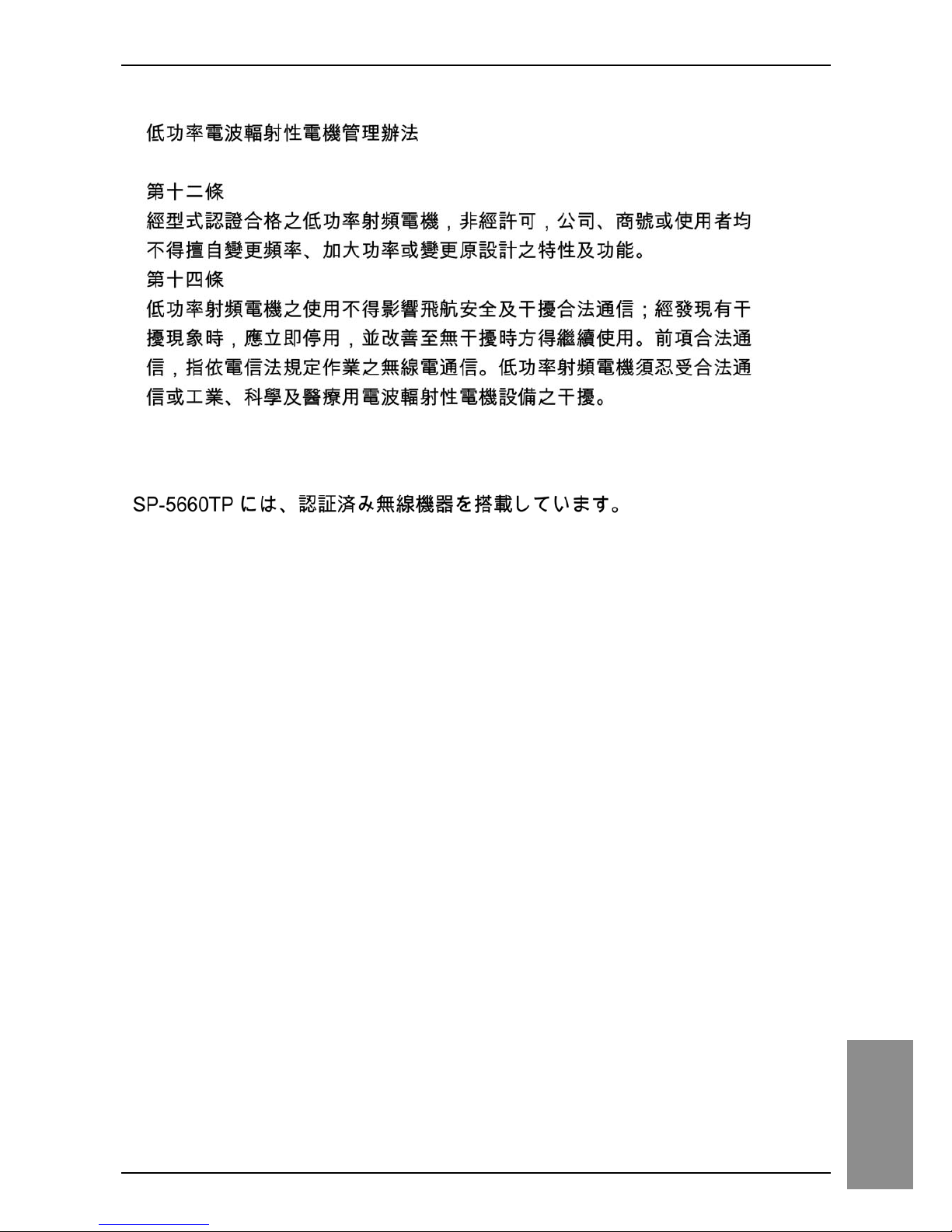
Taiwan
Japan
Page 55

56
WLAN
 Loading...