

Page 1
シリーズ
(ボックスモジュール)
取扱説明書
Page 2

3
English
Safety Information
Important Information.....................................................................................4
Model Numbers
Model Numbers..............................................................................................6
Overview
Package Contents..........................................................................................7
About the Manual...........................................................................................8
Global Code ...................................................................................................8
Language Settings (Only for Open Box)........................................................8
Part Numbers and Functions
SP-5B10 ........................................................................................................9
SP-5B40 .......................................................................................................10
LED Indications..............................................................................................11
Specifications
Electrical Specifications .................................................................................12
Environmental Specifications.........................................................................12
Interface
Interface Caution............................................................................................13
Serial Interface...............................................................................................13
Auxiliary Output/Speaker Output Interface (AUX)..........................................17
DVI-D Output Interface (for SP-5B40) ...........................................................18
Installation
Installation Procedure ....................................................................................20
Removal Procedure .......................................................................................23
USB Cable Clamp
USB Cable Clamp..........................................................................................25
AUX Connector
AUX Connector..............................................................................................28
Standards
Standards.......................................................................................................30
Please read the “Warning/Caution Information” on the attached
sheet before using the product.
Page 3

4
English
Safety Information
Important Information
Notice
Read these instructions carefully, and look at the equipment to become
familiar with the device before trying to install, operate, or maintain it. The
following special messages may appear throughout this documentation or on
the equipment to warn of potential hazards or to call attention to information
that clarifies or simplifies a procedure.
Page 4

5
Safety Information
English
PLEASE NOTE
Electrical equipment should be installed, operated, serviced, and maintained
only by qualified personnel. No responsibility is assumed by Pro-face for any
consequences arising out of the use of this material.
A qualified person is one who has skills and knowledge related to the
construction and operation of electrical equipment and its installation, and has
received safety training to recognize and avoid the hazards involved.
Page 5
6
English
Model Numbers
Model Numbers
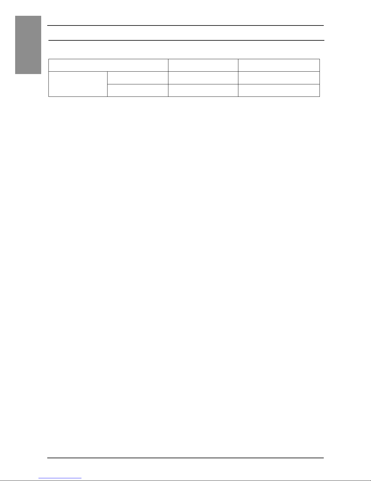
NOTE : These models can be connected to all models of SP5000 Series Display Module.
For the model numbers of the Display Module, refer to Model Names in the SP5000 Series
(Display Module) Installation Guide.
Series Model Name Model Number
SP5000 Series Power Box SP-5B10 PFXSP5B10
Open Box SP-5B40 PFXSP5B40
Page 6

7
English
Overview
Package Contents
The following items are included in the package. Before using this product,
please confirm that all items listed here are present:
1 SP5000 Series Box Module: 1
2 USB Clamp Type A (1 port): 2 sets for Power Box, 3 sets for Open Box (1
clip and 1 tie)
3 SP5000 Series (Box Module) Installation Guide (this guide): 1
4 Warning/Caution Information: 1
5 End-user License Agreement (only for Open Box): 2
This product has been carefully packed, with special attention to quality.
However, should you find anything damaged or missing, please contact your
local distributor immediately.
21
Page 7

8
English
Overview
About the Manual
This manual describes wiring and installation procedures. For more detailed
information, refer to the SP5000 Series Hardware Manual.
You can download the manual from our website “Otasuke Pro!” at:
http://www.pro-face.com/otasuke
Global Code
A global code is assigned to every Pro-face product as a universal model
number.
For more information on product models and their matching global codes,
please refer to the following URL.
http://www.pro-face.com/product/globalcode.html
Language Settings (Only for Open Box)
The factory setting of the operating system language is English. Change the
operating system language as required.
For details on changing the operating system language, refer to the following
URL.
http://www.pro-face.com/trans/en/product/1017.html
Page 8

9
English
Part Numbers and Functions
SP-5B10
A: Auxiliary Output/Speaker Output Interface (AUX)
B: Status LED (See page 11)
C: Card Access LED (See page 11)
D: USB (mini-B) Interface
E: Expansion Unit Interface Cover (EXT)
F: Storage Card Cover
G: System Card Cover
H: USB (Type A) Interface
I: Ethernet Interface (Ethernet1)
J: Ethernet Interface (Ethernet2)
K: Serial Interface (COM1)
L: Serial Interface (COM2)
Front
Right
Bottom
D
E
C
A
B
F
G
IJ K LH
Page 9

10
English
Part Numbers and Functions
SP-5B40
A: Auxiliary Output/Speaker Output Interface (AUX)
B: DVI-D Output Interface
C: AUDIO Input Interface (L-IN/MIC)
D: Status LED (See page 11)
E: Card Access LED (See page 11)
F: USB (Type A) Interface
G: USB (mini-B) Interface
H: Expansion Unit Interface Cover (EXT)
I: Storage Card Cover
J: System Card Cover
K: USB (Type A) Interface
L: Ethernet Interface (Ethernet1)
M: Ethernet Interface (Ehternet2)
N: Serial Interface (COM1)
O: Serial Interface (COM2)
Front
Right
Bottom
D
E
H
F
G
C
A
B
,
J
K
L
M
N
O
Page 10

11
Part Numbers and Functions
English
LED Indications
Status LED
*1 Only when your screen editing software supports the Logic Program.
NOTE : When the SP-5B40 is connected and the power cable is connected to the power
supply, even if the system is stopped the Display Module's Status LED will display red.
Card Access LED
Color Indicator SP-5B10 SP-5B40
HMI
Operation
Logic
Program
Operation
*1
HMI
Operation
Logic
Program
Operation
*1
Green ON Offline – Offline –
In
operation
RUN In
operation
RUN
Flashing In
operation
STOP In
operation
STOP
Orange Flashing Software starting up.
Red ON Power is turned ON.
Flashing In
operation
Major error In
operation
Major error
Red/Green Alternating Display Module connection error.
Orange/
Red
Alternating SD Card boot error –
– OFF Power is turned OFF.
Color Indicator SP-5B10 SP-5B40
Green ON Storage Card is
being accessed.
Storage Card or
System Card (OS) is
being accessed.
- OFF Storage Card is not
inserted or
accessed.
Storage Card or
System Card (OS) is
not accessed.
Page 11

12
English
Specifications
Electrical Specifications
Environmental Specifications
Specification SP-5B10 SP-5B40
Power Supply
Rated Input Voltage 12 Vdc (Supply from Display Module)
Power Consumption
(Primary Power Supply
[including power loss])
Max 25 W 35 W
When power is not
supplied to external
devices
12.5 W or less 22.5 W or less
Physical Environment
Surrounding Air
Temperature
0...60 °C (32...140 °F)
Storage
Temperature
-20...60 °C (-4...140 °F)
Surrounding Air and
Storage Humidity
10...90% RH (non-condensing, wet bulb
temperature 39 °C [102.2 °F] or less)
Dust
0.1 mg/m
3
(10-7oz/ft3) or less (non-conductive
levels)
Pollution Degree For use in Pollution Degree 2 environment
Page 12

13
English
Interface
Interface Caution
Serial Interface
For information on how to connect controllers and other types of equipment,
refer to the corresponding device driver manual of your screen editing
software.
The serial interface is not isolated. The SG (signal ground) and the FG
(functional ground) terminals are connected inside this product. When the
serial interface connector is D-Sub, connect the FG wire to the shell.
NOTE : Use within the rated current.
DANGER
ELECTRIC SHOCK AND FIRE
When using the SG terminal to connect an external device to this product:
• Verify that a short-circuit loop is not created when you set up the system.
• Connect the SG terminal to remote equipment when the external device is not
isolated. Connect the SG terminal to a known reliable ground connection to
reduce the risk of damaging the circuit.
Failure to follow these instructions will result in death or serious injury.
CAUTION
LOSS OF COMMUNICATION
• All connections to the communication ports must not put excessive stress on
the ports.
• Securely attach communication cables to the panel wall or cabinet.
Failure to follow these instructions can result in injury or equipment
damage.
Page 13
14
English
Interface
Connection for Serial Interface
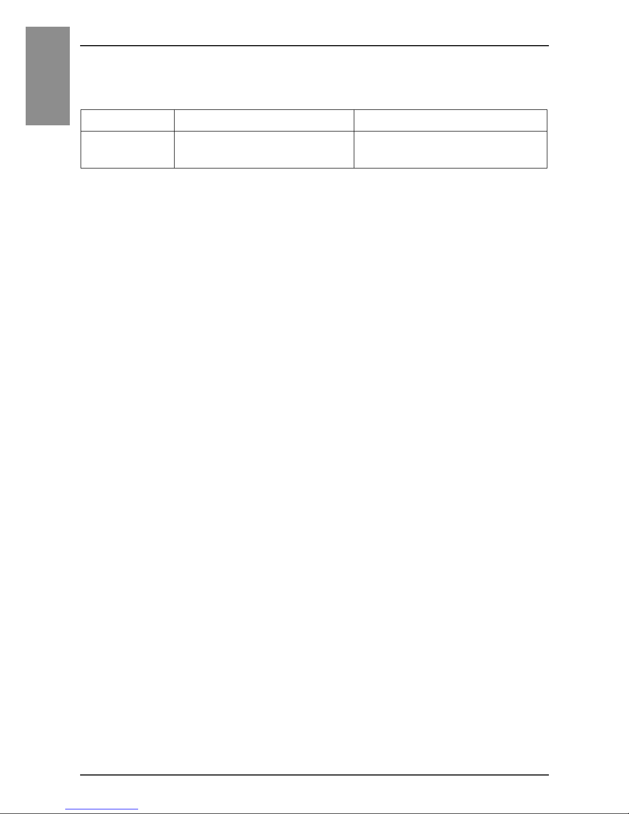
The Pin configuration of each serial interface is explained on the respective
reference page.
The communication method can be switched via your screen editing software. The initial setting is RS-422/RS-485.
COM1 COM2
SP-5B10/
5B40
RS-232C or RS-422/RS-485
(see page 15, 16)
RS-232C or RS-422/RS-485
(see page 15, 16)
Page 14
15
Interface
English
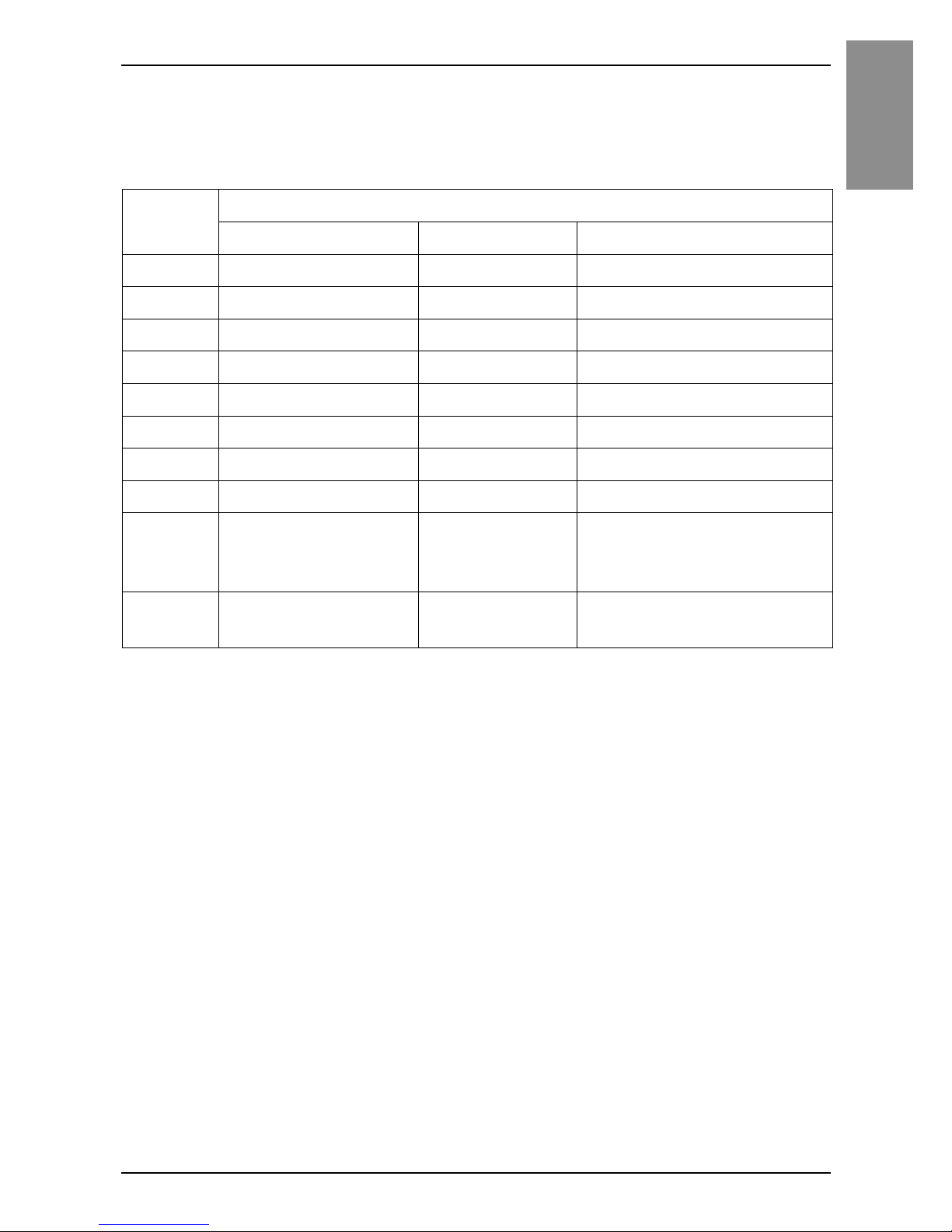
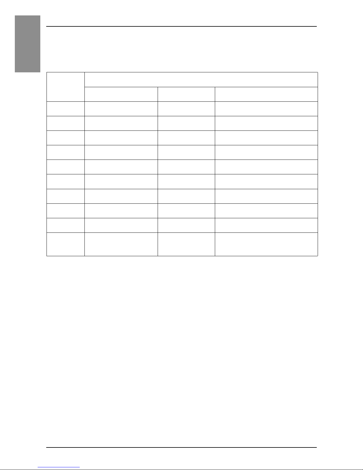
RS-232C
D-Sub 9 pin plug connector.
The communication method can be switched between RS-232C and RS-422/
RS-485 via your screen editing software.
*1 You can switch pin #9 between RI and VCC via your screen editing software. The VCC
output is not protected against overcurrent. To prevent damage or malfunction, use within
the rated current only.
*2 When using Open Box, use external equipment so that the sum of COM1 VCC output and
COM2 VCC output totals 0.25 A.
Interfit bracket is #4-40 (UNC).
Recommendations:
• Cable Connector: XM3D-0921 manufactured by OMRON Corporation.
• Cable Cover: XM2S-0913 manufactured by OMRON Corporation.
• Jack Screw (#4-40 UNC): XM2Z-0073 manufactured by OMRON
Corporation.
Pin
Number
RS-232C
Signal Name Direction Meaning
1 CD Input Carrier Detect
2 RD(RXD) Input Receive Data
3 SD(TXD) Output Send Data
4 ER(DTR) Output Data Terminal Ready
5 SG – Signal Ground
6 DR(DSR) Input Data Set Ready
7 RS(RTS) Output Request to Send
8 CS(CTS) Input Send Possible
9 CI(RI)/VCC Input/– Called Status Display
+5V±5% Output
0.25 A
*1*2
Shell FG – Functional Ground
(Common with SG)
Page 15
16
English
Interface
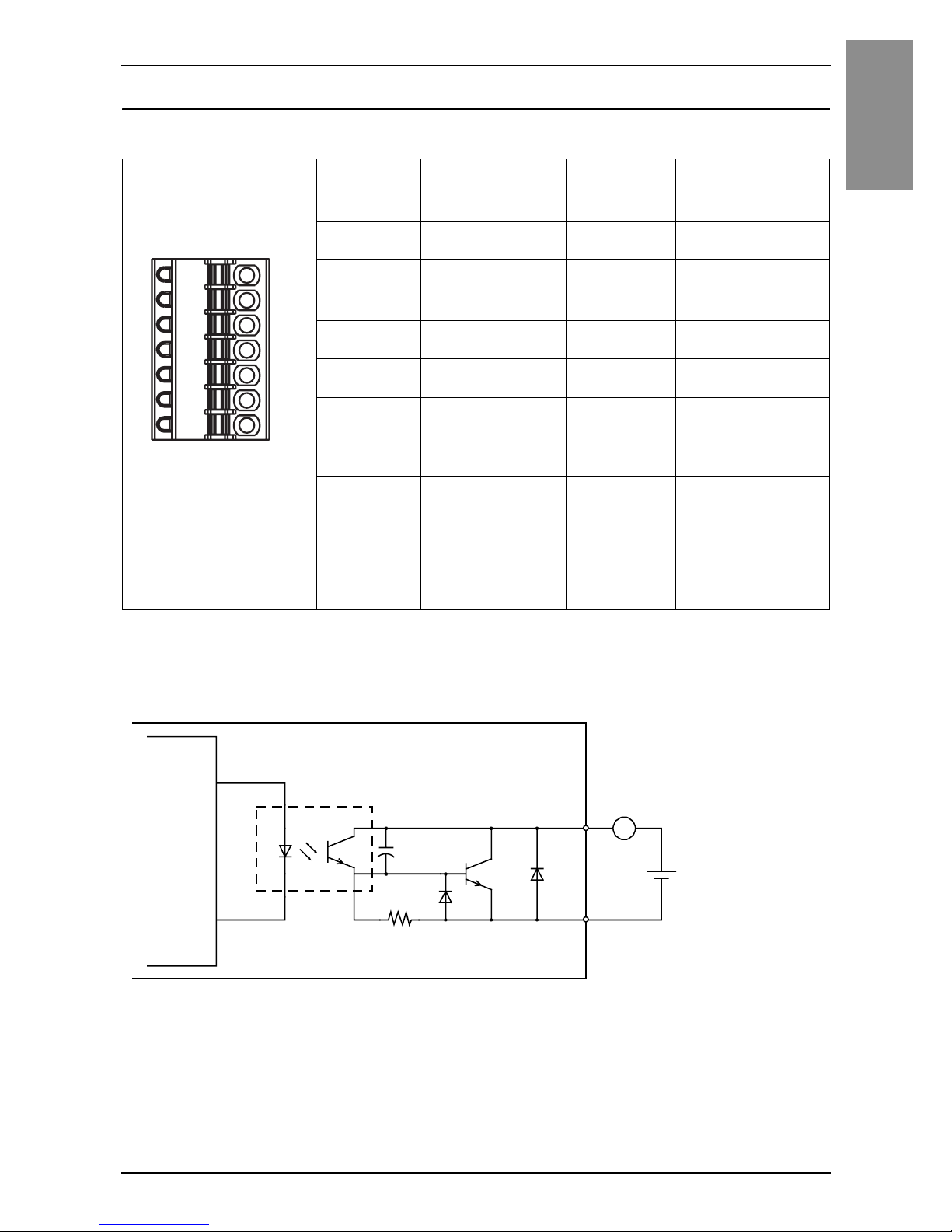
RS-422/485
D-Sub 9 pin plug connector.
The communication method can be switched between RS-232C and RS-422/
RS-485 via your screen editing software.
Interfit bracket is #4-40 (UNC).
Recommendations:
• Cable Connector: XM3D-0921 manufactured by OMRON Corporation.
• Cable Cover: XM2S-0913 manufactured by OMRON Corporation.
• Jack Screw (#4-40 UNC): XM2Z-0073 manufactured by OMRON
Corporation.
Pin
Number
RS-422/RS-485
Signal Name Direction Meaning
1 RDA Input Receive Data A (+)
2 RDB Input Receive Data B (–)
3 SDA Output Send Data A (+)
4 ERA Output Data Terminal Ready A (+)
5 SG – Signal Ground
6 CSB Input Send Possible B (–)
7 SDB Output Send Data B (–)
8 CSA Input Send Possible A (+)
9 ERB Output Data Terminal Ready B (–)
Shell FG – Functional Ground
(Common with SG)
Page 16
17
Interface
English
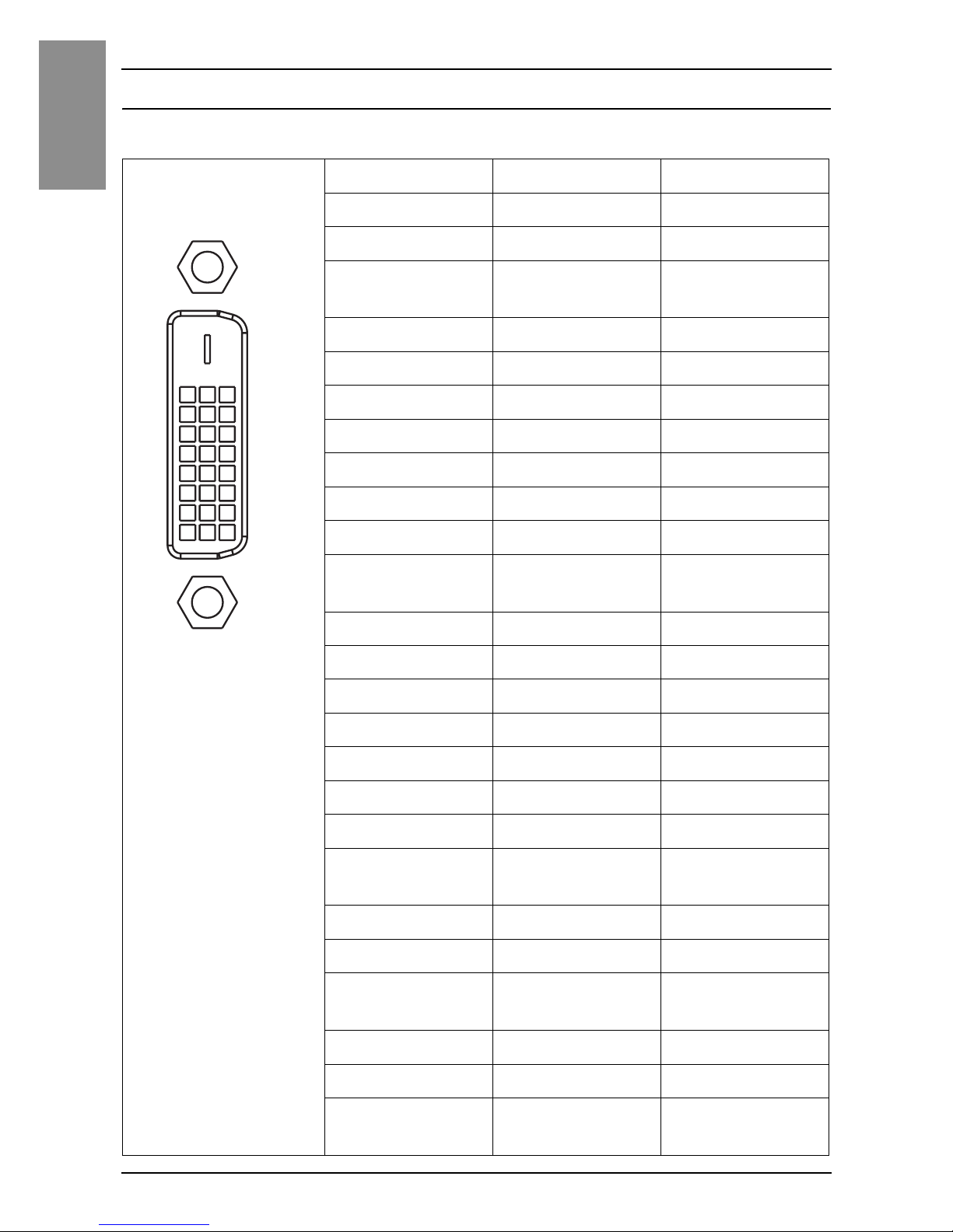
Auxiliary Output/Speaker Output Interface (AUX)
AUX Connector: PFXZCDCNAUX1 manufactured by Pro-face.
Output Circuit
A Internal Circuit
B Pin Number 6: ALARM+/BUZZER+
C Pin Number 7: ALARM-/BUZZERD Load
E External Power
Cable connection
side
Pin
Number
Signal Name Direction Meaning
1 LineOut Output Line Out
2
LineOut_GND
Output Line Out
Ground
3 SP+ Output Speaker +
4 SP- Output Speaker -
5 NC – No connection
6ALARM+/
BUZZER+
Output (Can be
changed via
your screen
editing
software)
7 ALARM-/
BUZZER-
Output
1
7
+
–
24 Vdc
A
B
C
D
E
470pF
.ȍ
Page 17
18
English
Interface
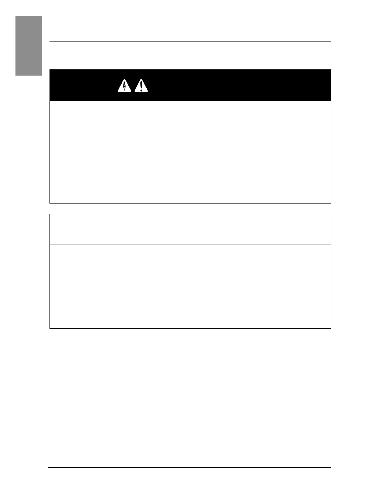
DVI-D Output Interface (for SP-5B40)
DVI-D 24 pin socket connector
Product Side Pin Number Signal Name Direction
1 TMDS DATA 2- Output
2 TMDS DATA 2+ Output
3TMDS DATA 2
SHIELD
-
4NC5NC6 DDC Clock Output
7 DDC Data Input/Output
8NC9 TMDS DATA 1- Output
10 TMDS DATA 1+ Output
11 TMDS DATA 1
SHIELD
-
12 NC 13 NC 14 +5V Power 15 GND Ground
16 NC 17 TMDS DATA 0- Output
18 TMDS DATA 0+ Output
19 TMDS DATA 0
SHIELD
-
20 NC 21 NC 22 TMDS CLOCK
SHIELD
-
23 TMDS CLOCK+ Output
24 TMDS CLOCK - Output
Shell FG Functional
Ground
117
824
Page 18

19
Interface
English
Recommendations:
DVI-D cable manufactured by Pro-face (FP-DV01-50 [5 m])
NOTE :
• For noise-free operation, use the recommended DVI-D cable.
• DVI-D output does not support Hot Plug Detect (HPD). Even when the main unit
power is on while connected to an external display, this product outputs the
display signal as XGA. If the external display does not support XGA input, the
screen will not display.
Page 19
20
English
Installation
Installation Procedure
Installing onto Display Module
Be aware of the following when building this product into an end-use product:
• This product is not approved as an enclosure. When building this product into an
end-use product, be sure to use an enclosure that satisfies standards as the enduse product’s overall enclosure.
• This product must be used indoors only.
DANGER
HAZARD OF ELECTRIC SHOCK, EXPLOSION OR ARC FLASH
• Remove all power from the device before removing any covers or elements of
the system, and prior to installing or removing any accessories, hardware, or
cables.
• Unplug the power cable from both the Display Module and the power supply.
• Always use a properly rated voltage sensing device to confirm power is off.
• Replace and secure all covers or elements of the system before applying
power to the Display Module.
Failure to follow these instructions will result in death or serious injury.
NOTICE
EQUIPMENT DAMAGE
• When mounting this product vertically, first install the Box Module onto the
Display Module before attaching the Display Module to the panel. When
installing the Box Module onto the Display Module, place the Display Module
on a clean and level surface with the screen facing downward.
• Only qualified personnel can change the primary battery.
Failure to follow the instruction can result in equipment damage.
Page 20
21
Installation
English
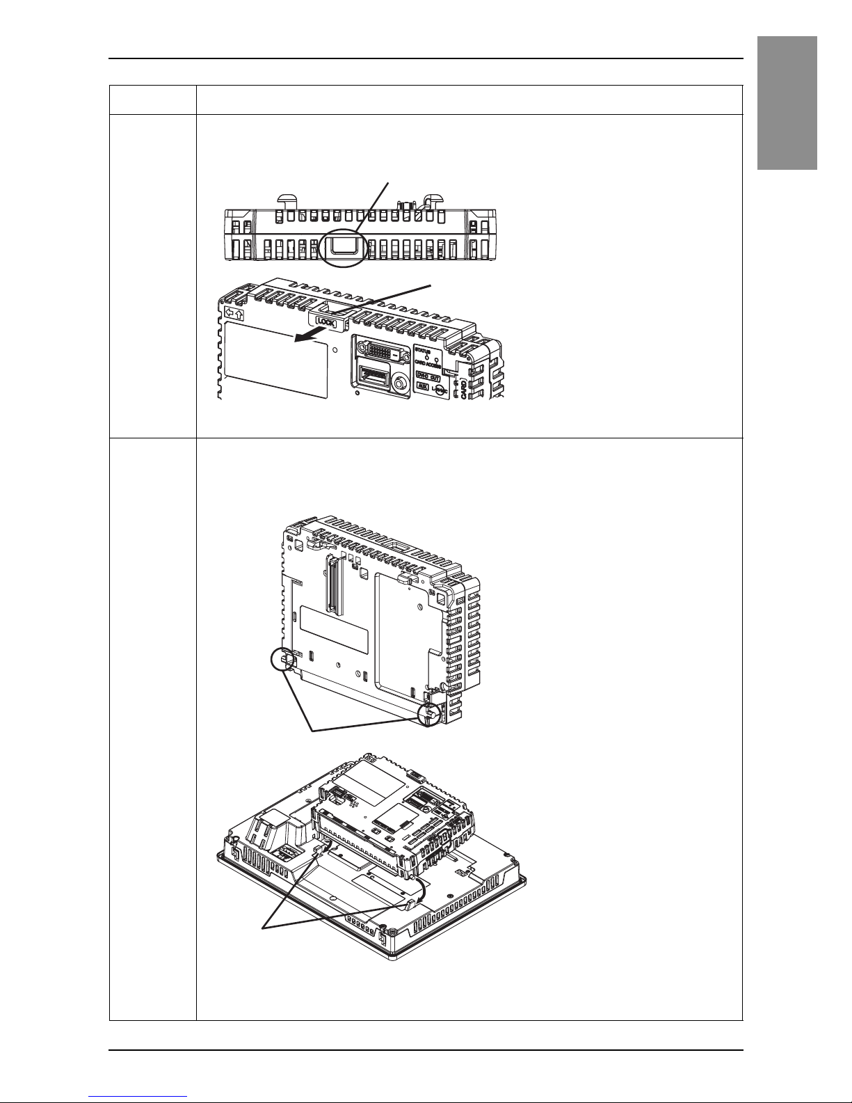
Step Action
1 Pull the LOCK forward on the top of the Box Module to release the
lock as illustrated.
1 LOCK
2 Insert the protruding points on the bottom left and right of the Box
Module into the two holes on the back of the Display Module to
attach the Box Module and Display Module together.
2 Protruding points
3 Holes for insertion
1
1
3
2
Page 21

22
English
Installation
NOTE : Refer to the SP5000 Series Hardware Manual or the SP5000 Series (Display
Module) Installation Guide on how to mount the Display Module to the panel.
3 Fully push on the LOCK on the top of the Box Module to mount the
Box Module on the Display Module.
1 LOCK
Step Action
1
Page 22

23
Installation
English
Removal Procedure
Removing from Display Module
DANGER
HAZARD OF ELECTRIC SHOCK, EXPLOSION OR ARC FLASH
• Remove all power from the device before removing any covers or elements of
the system, and prior to installing or removing any accessories, hardware, or
cables.
• Unplug the power cable from both the Display Module and the power supply.
• Always use a properly rated voltage sensing device to confirm power is off.
• Replace and secure all covers or elements of the system before applying
power to the Display Module.
Failure to follow these instructions will result in death or serious injury.
NOTICE
EQUIPMENT DAMAGE
When this product is mounted vertically, first remove the Display Module from
the panel, then remove the Box Module from the Display Module.
Failure to follow the instruction can result in equipment damage.
Step Action
1 When mounting this product vertically, remove the Display Module
from the panel and place the Display Module on a clean and level
surface with the screen facing down.
NOTE : Refer to the SP5000 Series Hardware Manual or the SP5000 Series
(Display Module) Installation Guide on how to remove the Display Module from
the panel.
Page 23

24
English
Installation
2 Release the LOCK on the top of the Box Module as illustrated.
1 LOCK
3 Lift up the Box Module in the direction indicated by arrow (A) in the
diagram and remove it by sliding in the direction indicated by arrow
(B).
CAUTION
RISK OF INJURY
Do not drop the Box Module when you remove it from the Display Module.
• Hold the unit in place after removing the fasteners.
• Use both hands.
Failure to follow the instruction can result in injury or equipment damage.
1
(A)
(A)
(B)
Page 24
25
English
USB Cable Clamp
USB Cable Clamp
When using a USB device, attach a USB cable clamp to the USB interface to
prevent the USB cable from being disconnected.
DANGER
POTENTIAL FOR EXPLOSION
• Verify that the power, input and output (I/O) wiring are in accordance with
Class I, Division 2 wiring methods.
• Substitution of any component may impair suitability for Class I, Division 2.
• Do not disconnect equipment while the circuit is live or unless the area is
known to be free of ignitable concentrations.
• Remove power before attaching or detaching any connectors to or from this
product.
• Ensure that power, communication, and accessory connections do not place
excessive stress on the ports. Consider the vibration in the environment when
making this determination.
• Securely attach power, communication, and external accessory cables to the
panel or cabinet.
• Use only commercially available USB cables.
• Use only non-incendive USB configurations.
• Suitable for use in Class I, Division 2, Groups A, B, C, D Hazardous Locations.
• Confirm that the USB cable has been attached with the USB cable clamp
before using the USB interface.
Failure to follow these instructions will result in death or serious injury.
Page 25
26
English
USB Cable Clamp
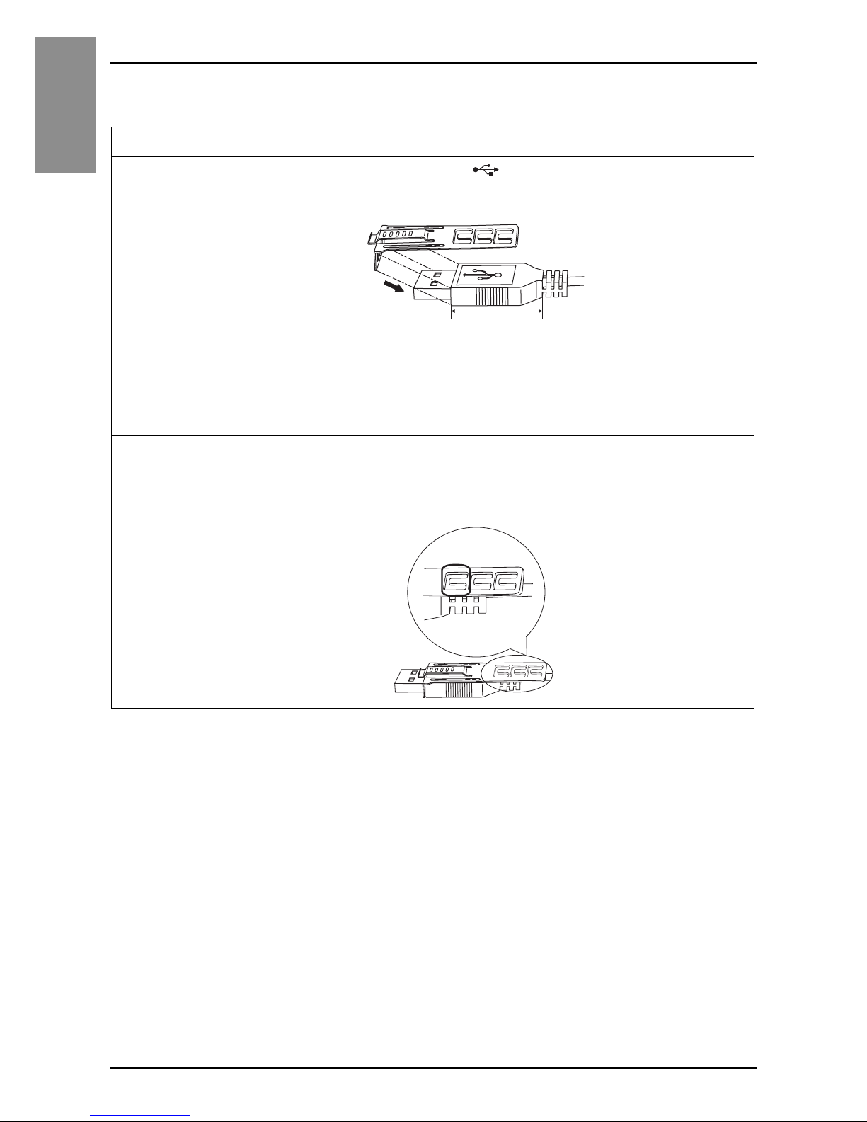
Attaching USB Clamp Type A (1 port)
NOTE : Watch your fingers. The edge of the clip is sharp.
Step Action
1 Mount the clip to the USB mark connector shell so that it
overlaps. The clip matches the 27 to 43.5 mm [1.06 to 1.71 inch]
length of the USB connector.
NOTE : When installing clamps to reduce cable stress onto both USB1 and
USB2, at USB1 overlay the clip on the side with the USB mark, and on USB2
the side without the USB mark. Make sure the ties do not interfere with the
other.
2 Align the clip and the USB cable connector shell. Adjust the
position of the holes where the clip is attached. To ensure stability,
select the clip-hole position that is closest to the base of the
connector shell.
27...43.5mm
[1.06...1.71 in.]
Pass the tie
through here.
Page 26

27
USB Cable Clamp
English
Removing USB Clamp Type A (1 port)
3 As shown, pass the tie through the clip hole. Next, turn the tie and
pass it through the head so that the USB cable can pass through
the center of the tie loop. The clip is now attached to the USB
cable.
NOTE :
• Check the direction of the head beforehand. Make sure the USB cable is
through the center of the tie loop and that the tie can pass through the
head.
• You can substitute the tie provided with PFXZCBCLUSA1 (manufactured
by Pro-face) or other commercially available ties with a width of 4.8 mm
[0.19 in.] and thickness of 1.3 mm [0.05 in.].
4 While pressing the grip on the clip, insert the cable from step 3 all
the way into the USB host interface. Make sure that the clip tab is
secured to the USB cable attached to this product.
Step Action
1 Remove the USB cable while pushing the grip section of the clip.
Page 27

28
English
AUX Connector
AUX Connector
CAUTION
ELECTRIC SHOCK
• Remove the AUX connector from this product prior to wiring.
• Strip wires only to the required length.
• Do not solder the wire itself.
Failure to follow these instructions can result in injury or equipment
damage.
Step Action
1 Insert the screwdriver into the opening button. This will open the
wire’s round-shaped hole.
2 Hold the screwdriver and insert the wire into the wire’s round-
shaped hole.
3 Take out the screwdriver from the opening button. The round-
shaped hole will then close, and the wire will be held securely in
place. To remove the wire, re-insert the screwdriver into the
opening button and when the wire’s spring clamp releases, pull the
wire out.
4 Insert the wired AUX connector into the Auxiliary Output/Speaker
Output Interface (AUX) of this product.
Page 28

29
AUX Connector
English
Recommendations:
• AUX Connector: PFXZCDCNAUX1 manufactured by Pro-face
• Screwdriver: SZS 0.4 X 2.0 (Product No. 1205202) manufactured by Phoenix
Contact
If you use another manufacturer, be sure the part has the following dimensions:
• point depth: 0.4 mm [0.02 in.]
• point height: 2.0 mm [0.08 in.]
Point shape should have isolation properties meeting DIN 5264 and
EN60900.
NOTE :
• Wire should be AWG 28 to AWG 20 thick and twisted.
• Applicable wire sizes are Style 1015 and Style 1007.
• Be sure to strip 8.0 mm (0.31 in.) of cover from the wire.
Page 29

30
English
Standards
Standards
For information on certifications and standards, such as certified models and
certificates, see the product markings or visit our website:
http://www.pro-face.com/worldwide.html
DANGER
POTENTIAL FOR EXPLOSION
• Suitable for use in Class I, Division 2, Groups A, B, C, and D Hazardous
Locations.
• Substitution of any component may impair suitability for Class I, Division 2.
• Do not disconnect equipment while the circuite is live or unless the area is
known to be free of ignitable gases concentrations.
• Always confirm that this product is suitable for use in hazardous locations by
checking that the ANSI/ISA 12.12.01 or CSA C22.2 N°213 certification
appears on the product labeling.
• Do not attempt to install, operate, modify, maintain, service, or otherwise alter
this product except as permitted in this manual. Unpermitted actions may
impair the suitability of this product for Class I, Division 2 operation.
• To power on or power off this product installed in a Class I, Division 2
hazardous location, you must either:
• Use a switch located outside the hazardous environment, or
• Use a switch certified for Class I, Division 1 operation inside the hazardous
area.
• Do not disconnect equipment unless power has been switched off or the area
is known to be non-hazardous. This applies to all connections including power,
ground, serial, parallel, and network connections.
• Never use unshielded/ungrounded cables in hazardous locations.
• When enclosed, keep enclosure doors and openings closed at all times to
avoid the accumulation of foreign matter inside the workstation.
Failure to follow these instructions will result in death or serious injury.
Inquiry
Do you have any questions about difficulties with your unit?
Please access our site any time that you need help with a solution.
http://www.pro-face.com/otasuke/
Page 30
31
English
Please be aware that Digital Electronics Corporation shall not be held liable
by the user for any damages, losses, or third party claims arising from the
uses of this product.
Notes
Page 31

32
English
blank_page
 Loading...