

Page 1

PS-3650A /PS-3651A
User Manual
Page 2

Preface
Thank you very much for purchasing a Pro-face PS-3650A/PS-3651A Unit, hereafter referred to as the PS-A.
Before using the PS-A, read this manual thoroughly to familiarize yourself with the PS-A’s operation procedures and
functions.
NOTICE
1. Copying this manual’s contents, either in whole or in part, is prohibited without the express permission of Digital
Electronics Corporation, Japan.
2. The information contained in this manual is subject to change without notice.
3. If you find any errors or omissions in this document, please contact Digital Electronics Corporation to report your
findings.
4. Regardless of Clause 3 above, Digital Electronics Corporation shall not be held responsible for any damage,
losses or third-party damage resulting from the use of this product.
Product names used in this manual are the trademarks / registere d trademarks of their respective owners.
© 2006 Digital Electronics Corporation. All rights reserved.
1
Page 3
Essential Safety Precautions
All safety-related procedures stated in this document must be followed to operate the PS-A correctly and safely. Be sure
to read this and any related documents thoroughly to understand the correct operation and functions of the PS-A unit.
Safety Icons
Throughout this manual, these icons provide essential safety information for PS-A operation procedures requiring special
attention. These icons indicate the following levels of danger:
Indicates situations where severe bodily injury, death or major equipment
damage can occur.
Indicates situations where slight bodily injury or minor equipment damage can
occur.
Indicates actions or procedures that should NOT be performed.
Indicates actions or procedures that MUST be performed to ensure correct
unit operation.
System Design
Do not create PS-A touch panel switches that could possibly endanger the safety of personnel or equipment. A malfunction of the PS-A unit, its I/O unit(s), cable(s), or other related equipment can cause unexpected output signals, leading to a serious accident. Be sure to design all important machine operation
switches so they are operated via a separate control system, and not via the PS-A.
Do not create PS-A touch panel switches to control machine safety operations, such as an emergency
stop switch. Install these switches as separate hardware switches, otherwise severe bodily injury or
equipment damage can occur.
Be sure to design your system so that a communication fault between the PS-A and its host controller will
not cause equipment to malfunction. This is to prevent any possibility of bodily injury or equipment damage.
Do not use the PS-A as a warning device for critical alarms that can cause serious operator injury,
machine damage or can halt system operation. Critical alarm indicators and their control/activator units
must be designed using stand-alone hardware and/or mechanical interlocks.
Do not use the PS-A with aircraft control devices, aerospace equipment, central trunk data transmission
(communication) devices, nuclear power control devices, or medical life support equipment, due to these
devices’ inherent requirements of extremely high levels of safety and reliability.
2
Page 4
Be sure to use redundant and/or failsafe system designs to ensure adequate levels of system reliability
and safety when using the PS-A with transportation vehicles (trains, cars and ships), disaster and crime
prevention devices, various types of safety equipment, non-life support related medical devices, and other
similar equipment.
After the PS-A unit’s backlight burns out the touch panel is still active, unlike the PS-A unit’s “Standby
Mode”. If the operator fails to notice that the backlight is burned out and touches the panel, a potentially
dangerous machine operation error can occur. Therefore, do not create PS-A unit touch panel switches
that may cause injury and/or equipment damage.
If your PS-A unit’s backlight suddenly turns OFF, use the following steps to determine if the backlight is
actually burned out.
1) If the PS-A unit’s “Backlight Control” is not set and the screen has gone blank, your backlight is burned
out.
2) If the PS-A unit’s “Backlight Control” is set to Standby Mode and the screen has gone blank, and touching the screen or performing another input operation does not cause the display to reappear, your
backlight is burned out.
Handling
Do not modify the PS-A unit. Doing so may cause a fire or an electric shock.
Do not operate the PS-A in an environment where flammable gases are present, since it may cause an
explosion.
Wiring
To prevent an electric shock be sure to disconnect your PS-A unit’s power cord from the power supply
before wiring the PS-A.
Do not use voltage beyond the PS-A unit’s specified range. Doing so may cause a fire or an electric
shock.
Maintenance
Do not connect or disconnect Host and PS-A unit communication cables while the PS-A is turned ON.
The PS-A uses a lithium battery for backing up its internal clock data and the battery may explode if it is
replaced incorrectly. When replacement is required, use a Pro-face-designated replacement product.
SEE
7.6 Replacing the Internal Battery (page7-15)
3
Page 5
Installation
Be sure all cable connectors are securely attached to the PS-A unit. A loose connection may cause
incorrect input or output signals.
Wiring
Be sure to ground the PS-A unit’s FG wire separately from other equipment FG lines. Also, be sure to use
a grounding resistance of 100Ω or less and a 2mm2 [0.0062inch2] or thicker wire, or your country's applicable standard. Otherwise, electric shock or malfunctions may result.
Be sure to use only the designated torque to tighten the PS-A unit’s terminal block screws. If these screws
are not tightened firmly, it may cause a short-circuit, fire or incorrect unit operation.
Be sure that metal particles and wiring debris do not fall inside the PS-A unit. They can cause a fire,
malfunction or incorrect unit operation.
Maintenance
Do not reset or turn the PS-A OFF , or insert or remove the CF Card while the PS-A unit’s CF Card or hard
disk is being accessed. Otherwise, CF Card and the hard disk internal data may be damaged or lost.
Unit Disposal
When the product is disposed of, it should be done so according to your country’s regulations for similar
types of industrial waste.
General Safety Precautions
Do not press on the PS-A unit’s display with excessive force or with a hard object, since it can damage the
display. Also, do not press on the touch panel with a pointed object, such as the tip of a mechanical pencil
or a screwdriver, since doing so can damage the touch panel.
Do not install the PS-A where the ambient temperature exceeds the specified range. Doing so may cause
a unit malfunction.
To prevent abnormally high temperatures from occurring inside the PS-A, do not restrict or block the PS-A
unit’s rear-face ventilation slots.
Do not operate the PS-A in areas where large, sudden temperature changes can occur. These changes
can cause condensation to form inside the PS-A, possibly causing it to malfunction.
Do not allow water, liquids or metal fragments to enter inside the PS-A unit’s case, since they can cause
either a malfunction or an electric shock. For use in Pollution Degree 2 environment.
Do not operate or store the PS-A in locations where it can be exposed to direct sunlight, high
temperatures, excessive dust, moisture or vibration.
4
Page 6
Do not operate or store the PS-A where chemicals evaporate, or where chemicals are present in the air.
Corrosive chemicals : Acids, alkalines, liquids containing salt
Flammable chemicals : Organic Solvents
Do not use paint thinner or organic solvents to remove dirt or oil from the PS-A unit’s surface. Instead, use
a soft cloth moistened with a diluted neutral detergent.
Do not use or store the PS-A in areas with direct sunlight, since the sun's ultraviolet rays may cause the
LCD’s quality to deteriorate.
Do not store the PS-A in an area where the temperature is lower than that recommended in the PS-A
unit’s specifications. Doing so may cause the LCD display’s liquid to congeal, which can damage the LCD.
Also, if the storage area’s temperature becomes higher than the specified level, the LCD’s liquid may
become isotropic, causing irreversible damage to the LCD. Therefore, only store the PS-A in areas where
temperatures are within the PS-A unit’s specifications.
After turning OFF the PS-A, be sure to wait a few seconds before turning it ON again. The PS-A may not
operate correctly if it is restarted too quickly.
Due to the possibility of unexpected accidents, be sure to back up the PS-A unit’s data regularly.
LCD Panel Usage Precautions
• The LCD panel’s liquid contains an irritant. If the panel is damaged and any of this liquid contacts your skin,
immediately rinse the area with running water for at least 15 minutes. If the liquid gets in your eyes, immediately rinse
your eyes with running water for at least 15 minutes and consult a doctor.
• The PS-A unit’s LCD screen may show unevenness in the brightness of certain images or at some contrast settings.
This is an LCD characteristic and not a product defect.
• The PS-A unit’s LCD screen pixels may contain minute black and white-colored spots. This is an LCD characteristic
and not a product defect.
• The color displayed on the PS-A unit’s LCD screen may appear different when seen from outside the specified
viewing angle. This is an LCD characteristic and not a product defect.
• When the same image is displayed on the PS-A unit’s screen for a long period, an afterimage may appear when the
image is changed. If this happens, turn off the PS-A, wait 10 seconds and then restart the unit. This is an LCD
characteristic and not a product defect.
• To prevent an afterimage:
• Set the PS-A unit’s display OFF feature when you plan to display the same screen image for a long period of time.
• Change the screen image periodically and try to not display the same image for a long period of time.
5
Page 7
This manual uses the following icons:
Indicates a warning or a product limitation. Be sure to follow the instructions
given with this icon to ensure the safe operation of the PS-A.
Contains additional or useful information.
Information Symbols
(1) (2)
*1 Indicates useful or important supplemental information.
SEE
Indicates steps used to accomplish a given task.
Be sure to follow these steps in the order they are written.
Indicates pages containing related information.
6
Page 8
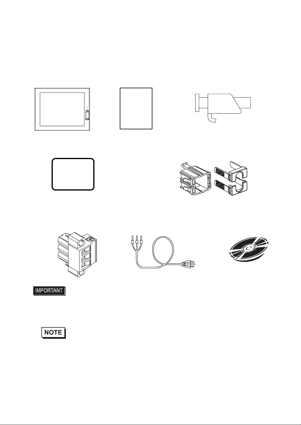
Package Contents
The following items are included in the PS-A unit’s package. Before using the PS-A, please check that all items listed
here are present.
PS-A Unit (1) Installation Guide (1) Installation Fasteners (4/set)
Installation
Guide
Installation Gasket (1) USB Holder (2) sets
(Attached to the PS-A unit) (USB Holder (1) + USB Cover (2)) x 2
Power Plug (1) Power Cable (1) CD-ROM (1)
(Attached to the PS-A unit)
• The power cord is designed only for AC100V use. Under other voltage situation, you
should use a different cord in conformity with the voltage.
• The power cord is exclusively for this product and it cannot be used for other electric
devices.
• The CD-ROM contains a User Manual and the software which includes PS-A Series Utility and
the driver. For details, please refer to "5.1 CD-ROM Contents".
• If your PS-A unit contains a built-in accessory, that accessory’s Installation Guide will also be
included in the PS-A’s packing box. Pl ease check that all items normally included with that
accessory are also included in this box.
This unit has been carefully packed, with special attention to quality. However, should you find anything damaged or
missing, please contact your local PS-A distributor immediately.
7
Page 9

UL/CSA Approval
PS3650A-T41, PS3651A-T41 are UL/CSA listed products (UL File No. E220851, CSA File No.219866)
Product Model No. UL/CSA Registration Model No.
PS3650A-T41 3480801-02
PS3651A-T41 3480801-01
Those products conform to the following standards:
• UL508 Industrial Control Equipment
• CSA-C22.2 No.142-M1987 Process Control Equipment
<Cautions>
Be aware of the following items when building the PS-A into an end-use product:
• The PS-A unit’s rear face is not approved as an enclosure. When building the PS-A unit into an end-use product, be
sure to use an enclosure that satisfies standards as the end-use product’s overall enclosure.
• The PS-A unit must be used indoors only.
• Install and operate the PS-A with its front panel facing outwards.
• If the PS-A is mounted so as to cool itself naturally, be sure to install it in a vertical panel. Also, it’s recommended that
the PS-A should be mounted at least 50 mm away from any other adjacent structures or machine parts. The temperature must be checked on the final product in which the PS-A is installed.
• For use on a flat surface of a Type 4X (Indoor Use Only) and/or Type 12 Enclosure.
CE Marking
PS3650A-T41, PS3651A-T41 are CE marked products that conform to EMC directive and Low-voltage directive.
<Compliant Standards>
•Safety
EN60950
•EMI
EN55011 ClassA
•EMS
EN61000-6-2
8
Page 10

Contents
Preface...................................................................................................................... 1
Essential Safety Precautions ....................................................................................2
Information Symbols .................................................................................................6
Package Contents .................................................................................................... 7
UL/CSA Approval ..................................................................................................... 8
CE Marking ............................................................................................................... 8
Contents.................................................................................................................... 4
Chapter 1 Introduction
1.1 Prior to Operating the PS-A Unit.....................................................................1-2
1.1.1 Front Access Mask ...............................................................................................1-3
1.1.2 Power Supply........................................................................................................1-3
1.2 System Design................................................................................................1-4
1.3 Accessories ....................................................................................................1-5
1.4 Part Names and Functions.............................................................................1-6
Chapter 2 Specifications
2.1 General Specifications....................................................................................2-2
2.1.1 Electrical ...............................................................................................................2-2
2.1.2 Environmental.......................................................................................................2-2
2.1.3 Structural...............................................................................................................2-3
2.2 Performance Specifications............................................................................2-4
2.2.1 Performance Specifications..................................................................................2-4
2.2.2 Display..................................................................................................................2-5
2.2.3 Touch Panel..........................................................................................................2-5
2.2.4 Expansion Slot......................................................................................................2-5
2.3 Interface Specifications...................................................................................2-6
2.3.1 Serial Interfaces (COM1)......................................................................................2-6
2.3.2 RAS Interface .......................................................................................................2-8
2.4 Dimensions.....................................................................................................2-9
2.4.1 PS-3650A External Dimensions ...........................................................................2-9
2.4.2 PS-3651A External Dimensions .........................................................................2-10
2.4.3 Panel Cut Dimensions ........................................................................................2-11
2.4.4 Installation Fasteners..........................................................................................2-11
2.4.5 Dimensions attached RS-232C/RS-485 exchangeable unit...............................2-12
4
Page 11

Chapter 3 Hardware Installation
3.1 Installation.......................................................................................................3-2
3.1.1 Installation Procedures ........................................... ... .... ... ... ... .... ... ... ... ... .... ... ... ... .3-2
3.2 Wiring Precautions..........................................................................................3-7
3.2.1 Connecting the Power Cord . ... ... ... ........................................................................3-7
3.2.2 Connecting the Power Supply.............................................................................3-10
3.2.3 Grounding............... ... ... ... .... ... ... ... .... ... ....................................... ... ... ... ... .... ... .....3-11
3.2.4 I/O Signal Line Placement ..................................................................................3-11
3.3 Peripheral Devices Installation.....................................................................3-12
3.3.1 Main Memory Installation........ ... ... .... ... ...............................................................3-12
3.3.2 PCI Board Installation............. ... ... .... ... ... ............................................................3-14
3.3.3 PCMCIA (PC Card) Installation/Removal ...........................................................3-16
3.3.4 CF Card Insertion/Removal ................................................................................3-17
3.3.5 USB Holder Attachment/Removal.......................................................................3-19
Chapter 4 System Setup
4.1 Setup Procedures........................................................................................... 4-2
4.2 System Parameters........................................................................................ 4-3
4.2.1 Main.............. ... ... .... ... ... ... ....................................... ... .... ... ....................................4-3
4.2.2 Advanced... ... ... ... .... ... ....................................... ... ... ... ....................................... ... .4-5
4.2.3 Intell .................................................................................. ... ... .... ........................4-14
4.2.4 Security... ... ... ....................................... ... ... ....................................... ... ... .... ........4-24
4.2.5 Boot............................... ... .... ...................................... .... ... ... ...............................4-25
4.2.6 Exit...... .... ...................................... .... ...................................... ............................4-26
Chapter 5 Setting up Software
5.1 CD-ROM Contents..........................................................................................5-2
5.1.1 Software Configuration ..................................... ... ... ... .... ... ... ... ..............................5-2
5.2 Setting Up Your PS-A Unit.............................................................................. 5-3
5.2.1 Setting Up an HDD with no Pre-installed OS........................................................5-3
5.2.2 Setting Up an HDD with Pre-installed OS.............................................................5-5
5.3 Installing Drivers............................................................................................. 5-7
5.4 Special Application Program Features............................................................ 5-9
5.4.1 Uninstalling Utility Software ................................................................................5-11
5.5 Cautions When Using Windows®2000/Windows®XP.................................. 5-12
5.5.1 Automatic System Log-on Setup ........................................................................5-12
5.5.2 Uninterrupted Power Supply System (UPS).......................................................5-12
5.5.3 Changing System Settings......................... ... .... ... ... ... .... ... ... ... .... ........................5-13
5.5.4 NTFS File System Conversion............................. ... ... .... ... ... ... .... ... ... ... ... .... ... ... ..5-13
5
Page 12

Chapter 6 Monitoring Features
6.1 RAS Features .................................................................................................6-2
6.1.1 PS-A RAS Features..............................................................................................6-2
6.1.2 RAS Feature Details.............................................................................................6-3
6.1.3 RAS Feature Overview.........................................................................................6-8
6.2 Monitoring the PS-A Status.............................................................................6-9
6.2.1 Setup Procedures.................................................................................................6-9
6.2.2 Monitoring Operation ..........................................................................................6-12
6.2.3 Error Messages ..................................................................................................6-14
6.3 Checking the Error Log List..........................................................................6-16
6.3.1 Error Message Display ......................... ... ...........................................................6-16
6.3.2 Error Type/Location and Error Action .................................................................6-18
6.4 Monitoring the PS-A Status from the Server ................................................6-20
6.4.1 System Configuration .........................................................................................6-20
6.4.2 Installation Procedures .......................................................................................6-21
6.4.3 Setup and Preparation of the Remote RAS Feature...........................................6-21
6.4.4 Read and Write of the System Monitor/RAS Feature........................ ... .... ... ... ... .6-23
6.4.5 Restrictions.........................................................................................................6-27
6.5 Restarting/shutting down the PS-A from the Server.....................................6-29
Chapter 7 Maintenance
7.1 Cleaning the Display.......................................................................................7-2
7.2 Cleaning the Fan Filter ...................................................................................7-3
7.3 Periodic Inspection Items................................................................................7-5
7.4 Replacing the Installation Gasket...................................................................7-6
7.5 Replacing the Backlight..................................................................................7-8
7.5.1 Procedure for replacing the backlight of PS-3650A..............................................7-9
7.5.2 Procedure for replacing the backlight of PS-3651A............................................7-12
7.6 Replacing the Internal Battery ......................................................................7-15
Appendices 1
1 I/O Map...........................................................................................................A-2
2 Memory Map...................................................................................................A-3
3 Interrupt Map ..................................................................................................A-4
4 License Agreement.........................................................................................A-5
6
Page 13

Memo
7
Page 14

1 Introduction
1. Prior to Operating the PS-A Unit
2. System Design
3. Accessories
4. Part Names and Functions
This chapter describes peripheral devices that can be connected to PS-A Series units along with the name and
functions of each part.
1-1
Page 15
PS-3650A / PS-3651A User Manual
1.1 Prior to Operating the PS-A Unit
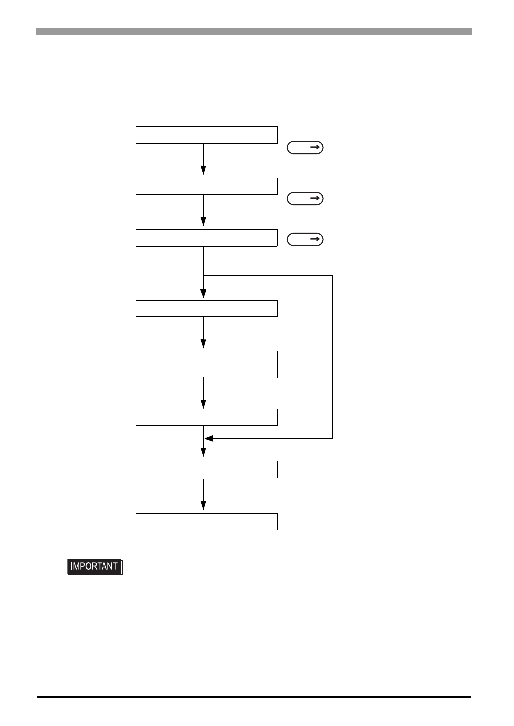
The following procedures are prior to use the PS-A unit.
Connect Peripheral Devices
[When PS-A has no preinstalled OS]
Install a commercial OS
in your PS-A. For how to
setup the OS, refer to
the manual provided
with the product.
Install PS-3650A/PS-3651A
User Manual and Driver CD Data
Install Required Device Drivers
Connect Power
Set Up the System
[When PS-A has preinstalled OS]
Install an OS
Connect the display unit and any optional devices.
SEE
Connect the PS-A unit's power cord to AC Interconnection and turn the power switch ON.
SEE
Configure the PS-A unit's BIOS.
SEE
1.2 System Design (page1-3)/1.3
Accessories (page1-4)
3.2 Wiring Precautions (page3-7)
4.1 Setup Procedures (page4-2)
1-2
Install all required software. For software instal-
Install Required Software
Install the PS-A Unit
• After hardware setup is completed, the OS must be used to create partitions and
format (initialize) the HDD before any data or applications can be saved to the
hard disk drive. For details concerning these procedures, refer to the OS
manufacturer's instruction manual.
• Whenever you turn the PS-A unit's power OFF, wait until the internal HDD stops
spinning (approximately 5 seconds) before turning the power ON again.
• The PS-A’s hard disk is designed for use with the Windows
Other operating systems do not support this driver software, etc
lation instructions, refer to the manual provided
with that product.
®
2000, Windows®XP.
Page 16
1.1.1 Front Access Mask
When you open the front maintenance hatch of the front unit, there are USB ports and a reset switch. If you
want to prevent unwilling or unintentional accesses, change the DipSW settings to mask access from reset
from the front side or the USB ports.
See the following for the place of the DipSW.
Chapter 1 Introduction
SEE
2.3 Interface Specifications Switch (page2-6)
1.1.2 Power Supply
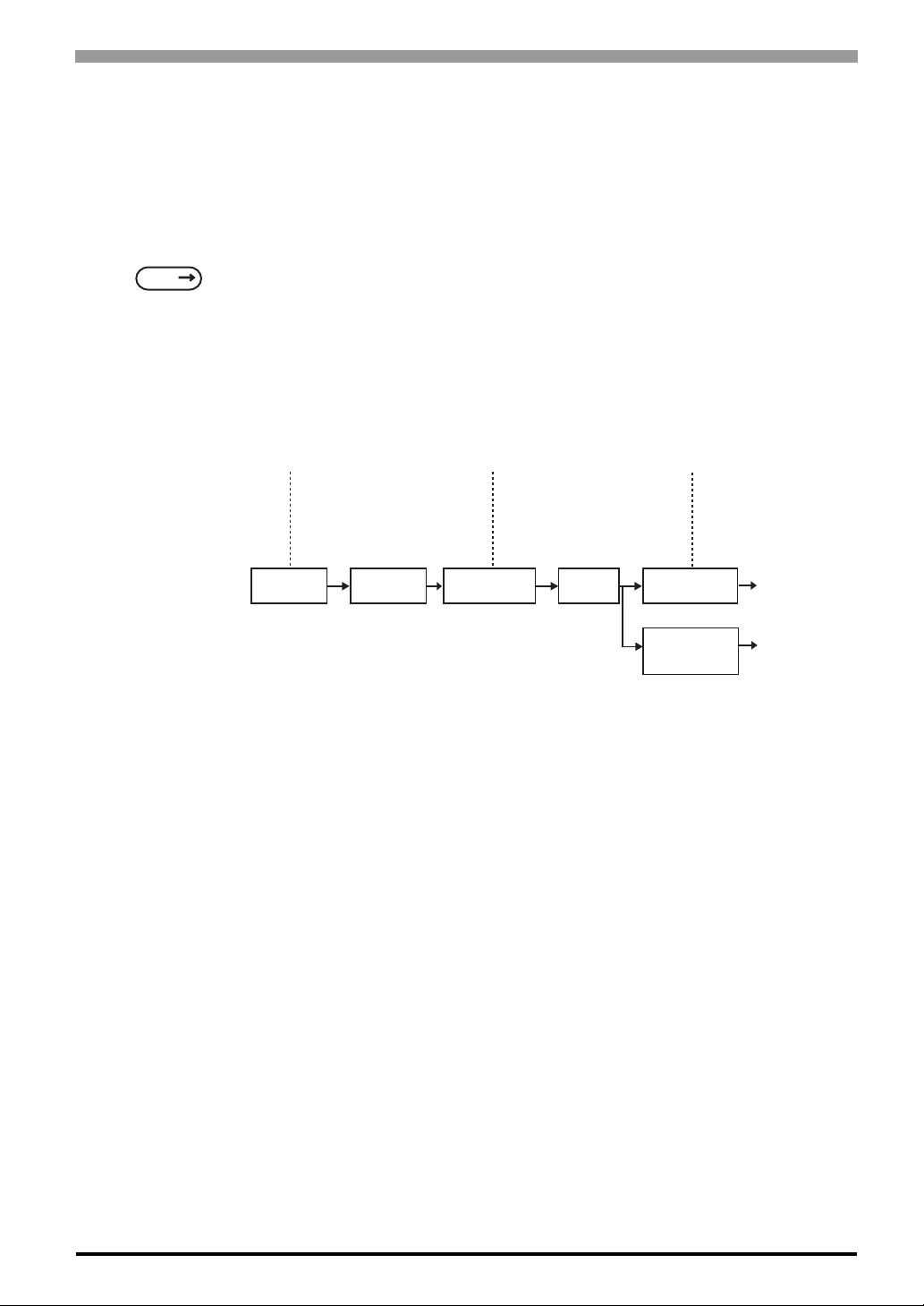
About states of PS-A’s power supply, there are three kinds of states, which are No Energization, Active State
(Normal), and Soft OFF State
Power State :
Screen of PS-A :
Power LED :
No Energization
OFF
OFF
PS-As
power On
*1
. Each state is outlined in the following.
Active State (Normal)
ON
Green Lighting
PS-A’s system
activated
Shut down by
Windows program
Soft OFF
OFF
Green Blinking
System
Stop
Reset Switch ON
Power Switch OFF,
Remove Power
Cable
for Normal State
for No Energization
State
*1 The Soft OFF refers to the state that Windows
®
has been shut down and the power is provided only for
the electric circuit to boot system. This Soft OFF State is different from what is System Standby set by
®
Windows
.
1-3
Page 17
PS-3650A / PS-3651A User Manual
1.2 System Design
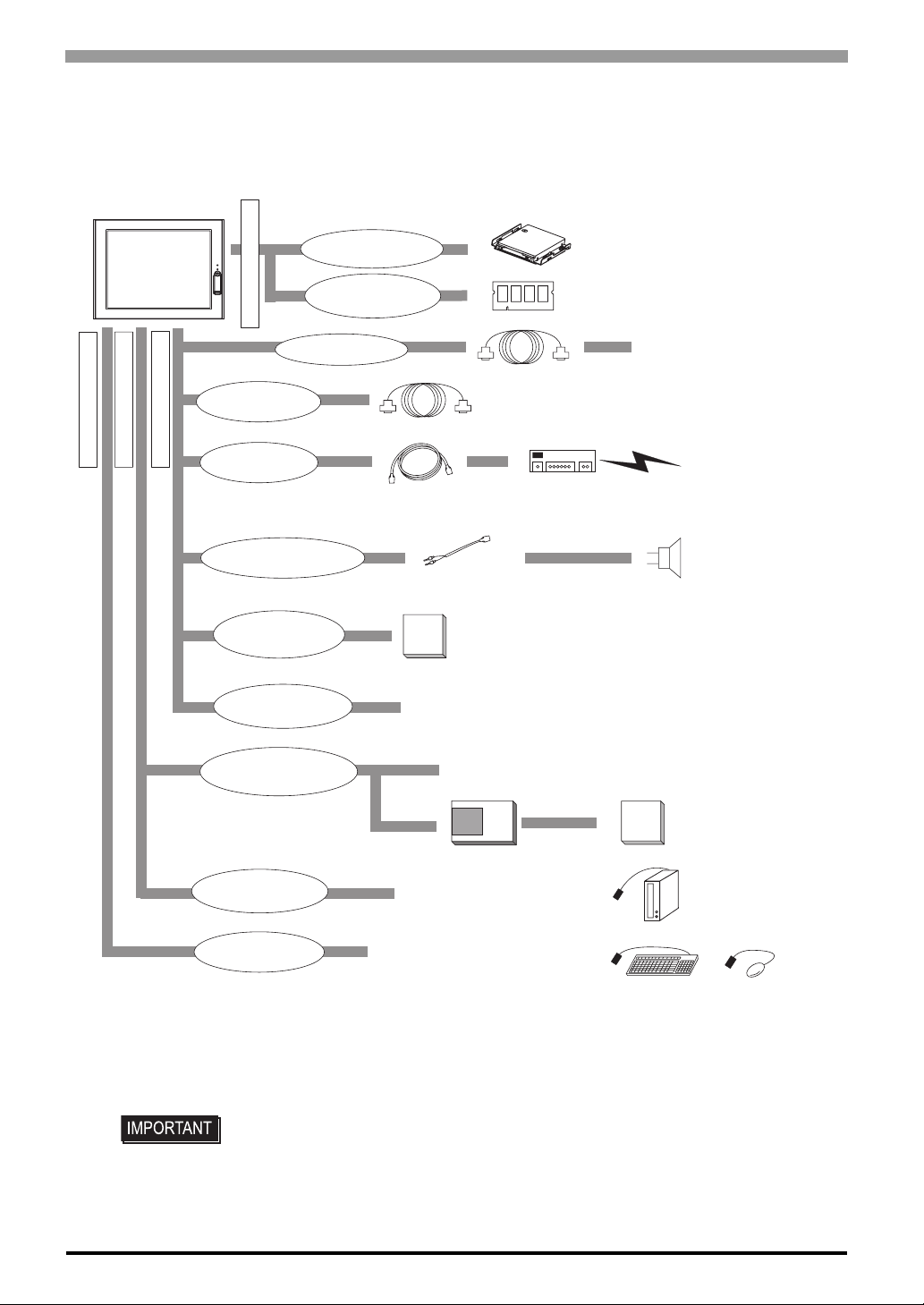
The following diagram illustrates the standard range of items that can be connected to the unit.
PS-3650A/PS-3651A
Front of PS-A unit
Side of PS-A unit
Inside PS-A unit
RAS Connector
LAN Connector
Bottom of PS-A unit
(2 ports)
Speaker Out Connector
CF Card Slots
(1 port, TypeII)
Expansion Board
Slot *³ (1 port)
IDE Connector
Main Memory
Connector
COM1
RAS Cable (Your own cable)
10BASE-T/100BASE-TX
Cable (commercial type)
Pin-jack Cable
(commercial type)
CF
PCI Board
(commercial type)
Serial Cable
CF Cards
HDD Unit
DIM Module
Hub
*¹*²
*¹*²
Peripherals
(commercial type)
Central Network Line
Speaker
*²
PCMCIA Slot
(1 port)
USB Connectors
(4 ports)
USB Connector
(1 port)
*1 Built-in accessory only
*2 The Pro-face's optional devices used with the PS-A. Please refer to “1.3 Accessories”for details.
*3 PS-3651A does not have an expansion board slot. PS-3650A only does.
USB 1.1 Compatible
Peripherals(commercial type)
PCMCIA Card
(commercial type)
CF Card Adaptor
USB 2.0 or 1.1 Compatible
Peripherals(commercial type)
*²
CF
USB HDD/DVD-RW
USB Key Board USB Mouse
• This diagram shows only the PS-A’ s internal layout and connectable devices. The
user’s actual design may differ.
1-4
CF Cards
*²
etc.
etc.
Page 18

1.3 Accessories
All accessories listed here are produced by Pro-face.
Optional Item
Product Name Model No. Description
Chapter 1 Introduction
DIM module
Hard Disk Unit PS365XA-HD40
CF Card
RS-232C/RS-485
conversion unit
PSA-DDR512 Memory module 512M Bytes
PSA-DDR1G Memory module 1G Bytes
HDD Unit mounted a Type 2.5 Hard Disk
(40G Bytes without OS)
CA3-CFCALL/128MB-0 Type 1 128M Bytes
CA3-CFCALL/256MB-0 Type 1 256M Bytes
CA3-CFCALL/512MB-0 Type 1 512M Bytes
CA6-CFCALL/1GB-01 Type 1 1G Bytes
PL-RC500
Unit for converting the RS-232C I/F to RS-
485 I/F.
Maintenance Items
Product Name Model No. Description
Installation Fastener CA3-ATFALL-01
Installation Gasket CA3-WPG12-01
Used to install the PS-A into a solid panel
(4 pieces per a set).
Provides dust and moisture resistance
when PS-A is installed into a solid panel.
Replacement Backlight CA5-BLU12XGA-01 Backlight for replacement
Disposable sheet that protects the PS-A
Protective panel sheet CA5-DFS10-01
unit’s screen and prevents from dust.
(5 sheets/set) (Hard type)
1-5
Page 19
PS-3650A / PS-3651A User Manual
1.4 Part Names and Functions
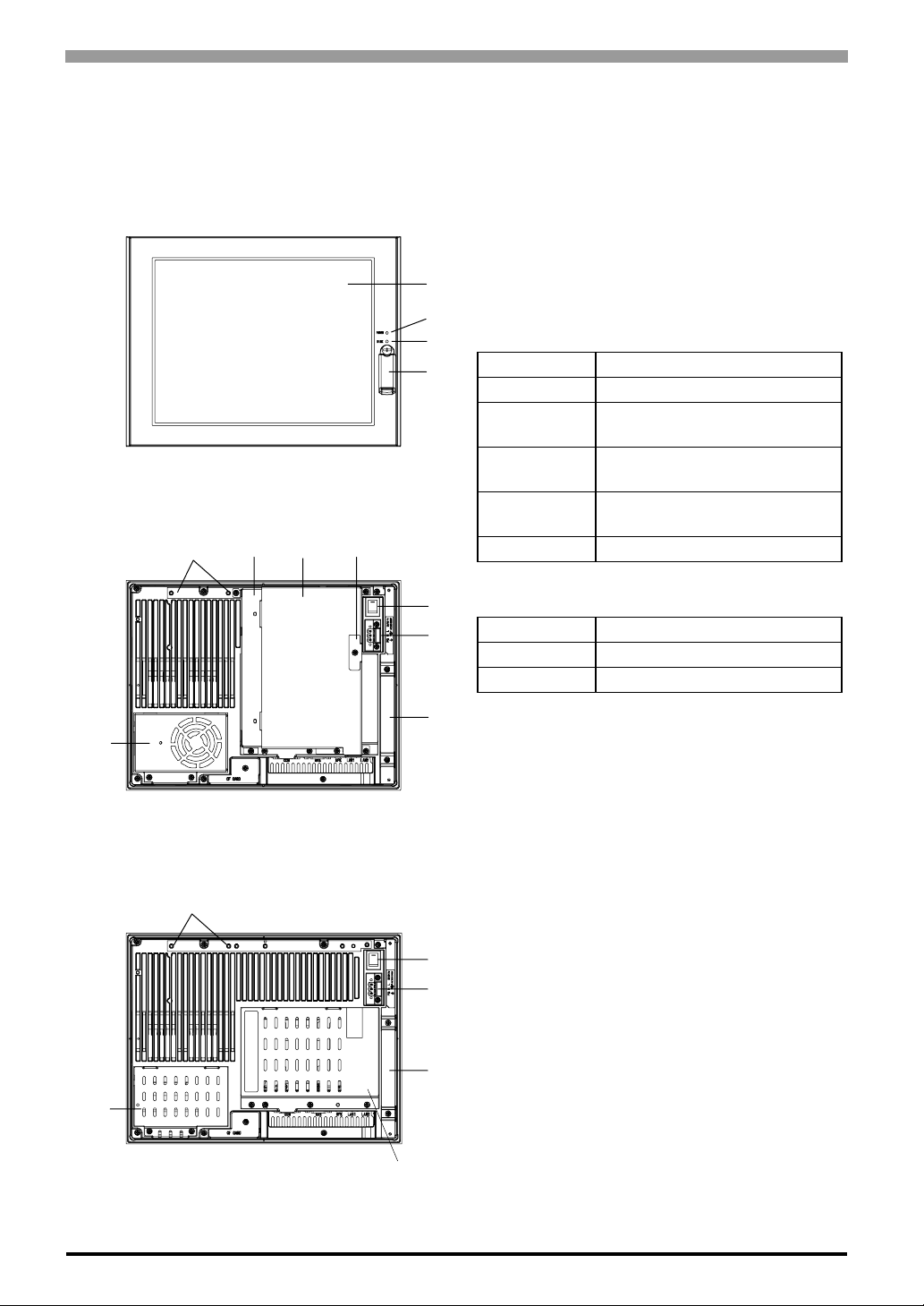
The following images are of a PS-3650A/PS-3651A unit.
Front
(Common in PS-3650A / PS-3651A)
IJKL
A: Display
B: Touch Panel
C: Power LED / RAS Status lamp (POWER)
A,B
C
D
E
This status LED indicates the electric conduction
status and operation status. The following table
shows the display colors and corresponding status.
LED PS-A Status
Green (lit) Normal operation (power is ON).
Green
(blinking)
Orange (lit)
Orange/ Red
(blinking)
Lit off Power is OFF.
System is NOT running (Soft
OFF state).
System monitor error / Touch
panel SELF TEST error.
Backlight error.
D: HDD/IDE Access lamp (DISK)
F
G
H
M
Rear
(PS-3650A)
I
F
G
H
N
LED PS-A Status
Green (lit) Access to HDD or IDE.
Lit off Not access to HDD or IDE.
E: Front Cover
When you opened it, there are a Hard Ware Reset
Switch (RESET) and a USB connector
(corresponding to USB Ver.1.1) inside.
F: Power switch
G: Power supply connector
For connection, put a power plug, which is together
in the package, into the power cable.
H: Mask Cover
I: RS-232C/485 converting unit hook holes
J: Expansion Board Base
K: Expansion Board Cover
L: Expansion Board Support
M: Fan Cover
N: Memory Slot Cover
1-6
Rear
(PS-3651A)
O
O: IDE Cover
Page 20
Left Side
(PS-3650A)
Chapter 1 Introduction
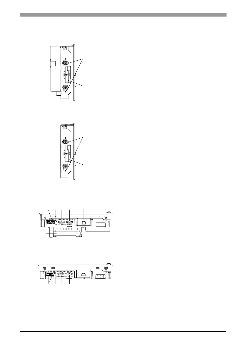
P: USB Interface (USB)
This interface corresponds to USB Ver.2.0. It uses
P
Q
P
TYPE-A connector. It connects to the devices
corresponding to USB.
Q: PCMCIA Slot Cover
Left Side
(PS-3651A)
RS T U V
W
Bottom
(PS-3650A)
RSTU V
Bottom
(PS-3651A)
Q
R: Ethernet Interface (LAN)
This interface corresponds to IEEE802.3, the
Ethernet protocol (10BASE-T/100BASE-TX). It
uses a modular jack connector which is RJ-45 type
(Octupole).
S: Speaker Output Interface
It connects to the Speaker.
T: RAS interface (RAS)
U: Serial Interface (COM1)
(R1/+5V Switching available)
V : CF Card Cover
W: Expansion Slot
This is a slot that is mounted on a PCI board.
1-7
Page 21

PS-3650A / PS-3651A User Manual
Memo
1-8
Page 22

2 Specifications
1. General Specifications
2. Performance Specifications
3. Interface Specifications
4. Dimensions
This chapter describes the general, functional and interface specifications of the PS-A as well as its part
names and dimensions.
2-1
Page 23
PS-3650A / PS-3651A User Manual
2.1 General Specifications
2.1.1 Electrical
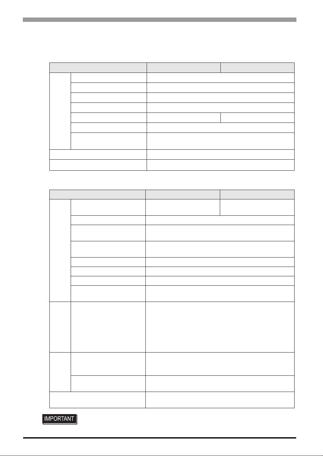
Input Voltage AC100/240V
Rated Voltage AC85 to 265V
Rated Frequency 50/60Hz
Allowable Voltage Drop 2.0ms (max.)
Power Consumption 110VA (100W) (max.) 95VA (50W) (max.)
Power Supply
leakage Current 2.0mA (max.)
In-Rush Current
Voltage Endurance AC1500V 20mA for 1 minute
Insulation Resistance
2.1.2 Environmental
Surrounding Air
Temperature
Storage Temperature -10°C ~ +60°C
Ambient Humidity
Storage Humidity
Physical
Dust Free of dust
Pollution Degree For use in Pollution Degree 2 environment
Corrosive gas Free of corrosive gas
Atmosphere (Using height)
Vibration Resistance
Mechanical
Noise Immunity
(via noise simulator)
Electrostatic
Electrical
Discharge Immunity
Noise Immunity
(Fast Transient Burst Noise)
PS-3650A PS-3651A
For AC100V(Ambient Temperature):30A(max.)
For AC240V(Ambient Temperature):50A(max.)
DC500V 10MΩ (min.)
PS-3650A PS-3651A
0°C to 50°C
(HDD use: 5 ~ 50°C)
10%RH ~ 85%RH
(Wet bulb temperature: 29°C max. - no condensation.)
10%RH ~ 85%RH
(Wet bulb temperature: 29°C max. - no condensation.)
800 ~ 1114hPa
(-300 ~ 2000m))
<When not using HDD>
IEC61131-2 compliant
5Hz to 9Hz single-amplitude 3.5mm
9Hz to 150Hz constant-accelerated velocity 9.8m/s
X, Y, Z directions 10 time (100minutes)
2
4.9m/s
10Hz to 25Hz X, Y, Z directions (30min. each)
6kV (complies with IEC61000-4-2 Level 3)
Power supply line : 2kV (IEC61000-4-4)
<When using HDD>
Noise Voltage: 1,500Vp-p
Pulse Duration: 50ns, 500ns, 1µs
Rise Time: 1ns
COM port: 1kV (IEC61000-4-4)
0°C to 50°C
(HDD use: 5 ~ 45°C)
2
2-2
• When using any of the PS-A’s optional devices, be sure to check that device’s
specifications for any special conditions or cautions that may apply to its use.
Page 24
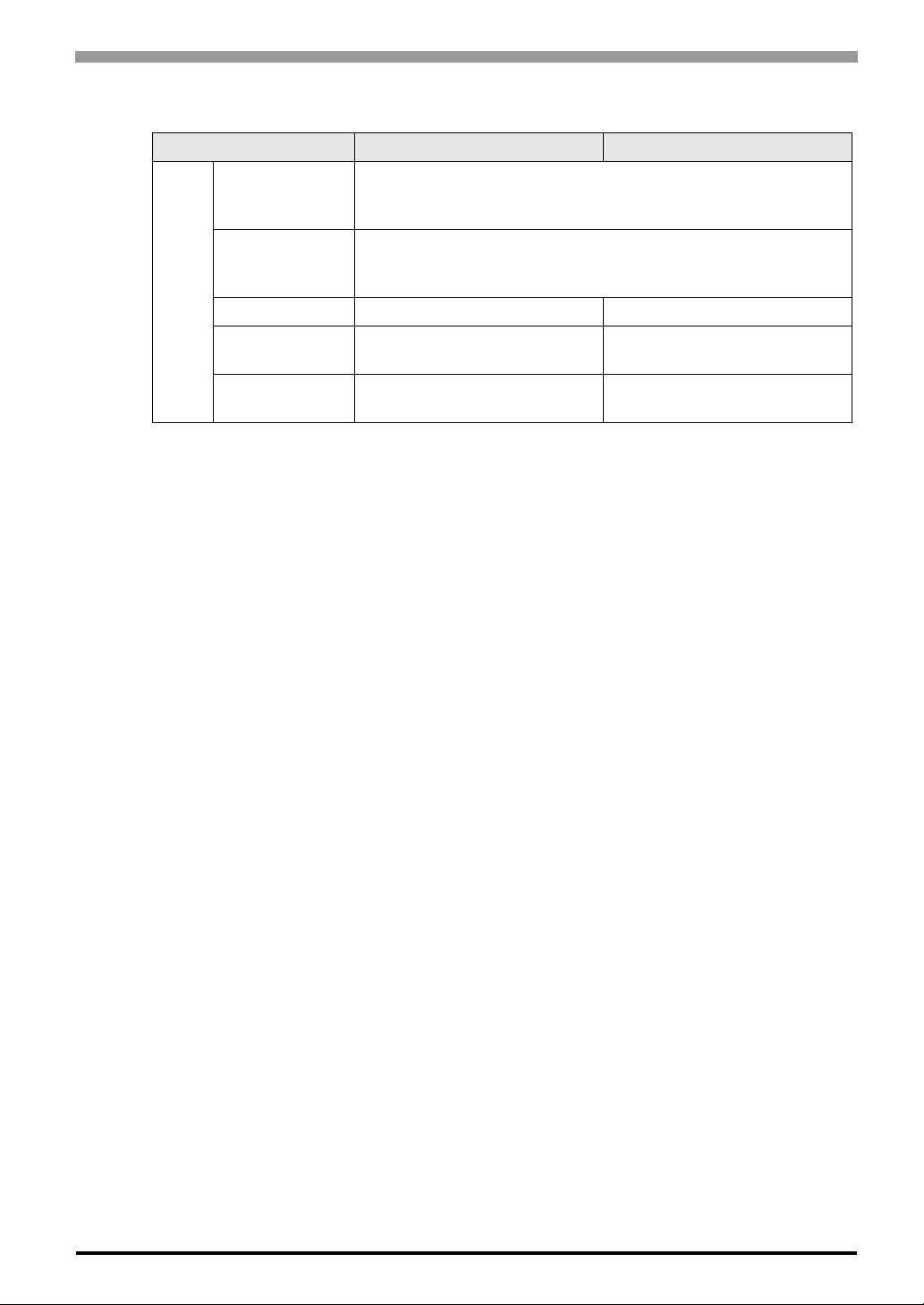
2.1.3 Structural
Installation
*1 The front face of the PS-A unit, installed in a solid panel, has been tested using conditions equivalent to
the standards shown in the specification. Even though the PS-A unit’s level of resistance is equivalent to
these standards, oils that should have no effect on the PS-A can possibly harm the unit. This can occur in
areas where either vaporized oils ar e present, or wher e low viscosity cutting oils are al lowed to adhere to
the unit for long periods of time. If the PS-A’s front face protection sheet becomes peeled off, these
conditions can lead to the ingress of oil into the PS-A and separate protection measures are suggested.
Also, if non-approved oils are present, it may cause deformation or corrosion of the front panel’s plastic
cover. Therefore, prior to installing the PS-A be sure to confirm the type of conditions that will be
present in the PS-A’s operating environment.
If the installation gasket is used for a long period of time, or if the unit and its gasket are removed from
the panel, the original level of the protection cannot be guaranteed. To maintain the original protection
level, be sure to replace the installation gasket regularly.
Chapter 2 Specifications
PS-3650A PS-3651A
Grounding resistance of 100 Ω, 2mm2 [0.0062inch2] or thicker wire,
Grounding
Structure
Cooling Method Forced cooling by fan Natural air circulation
Weight
External
Dimensions
or your country’s applicable standard. (Same for FG and SG
terminals)
Rating*1: Equivalent to IP65f (Only not using Front USB)
figuration: Built-in type
Installation method: Embedding
Approx. 4.5kg [9.9lb]
(unit only)
W313mm [12.32in.] × H239mm
[9.41in.] × D103mm [4.06in.]
Approx. 3.8kg [8.4lb]
(unit only)
W313mm [12.32in.] × H239mm
[9.41in.] × D60mm [2.36in.]
2-3
Page 25
PS-3650A / PS-3651A User Manual
2.2 Performance Specifications
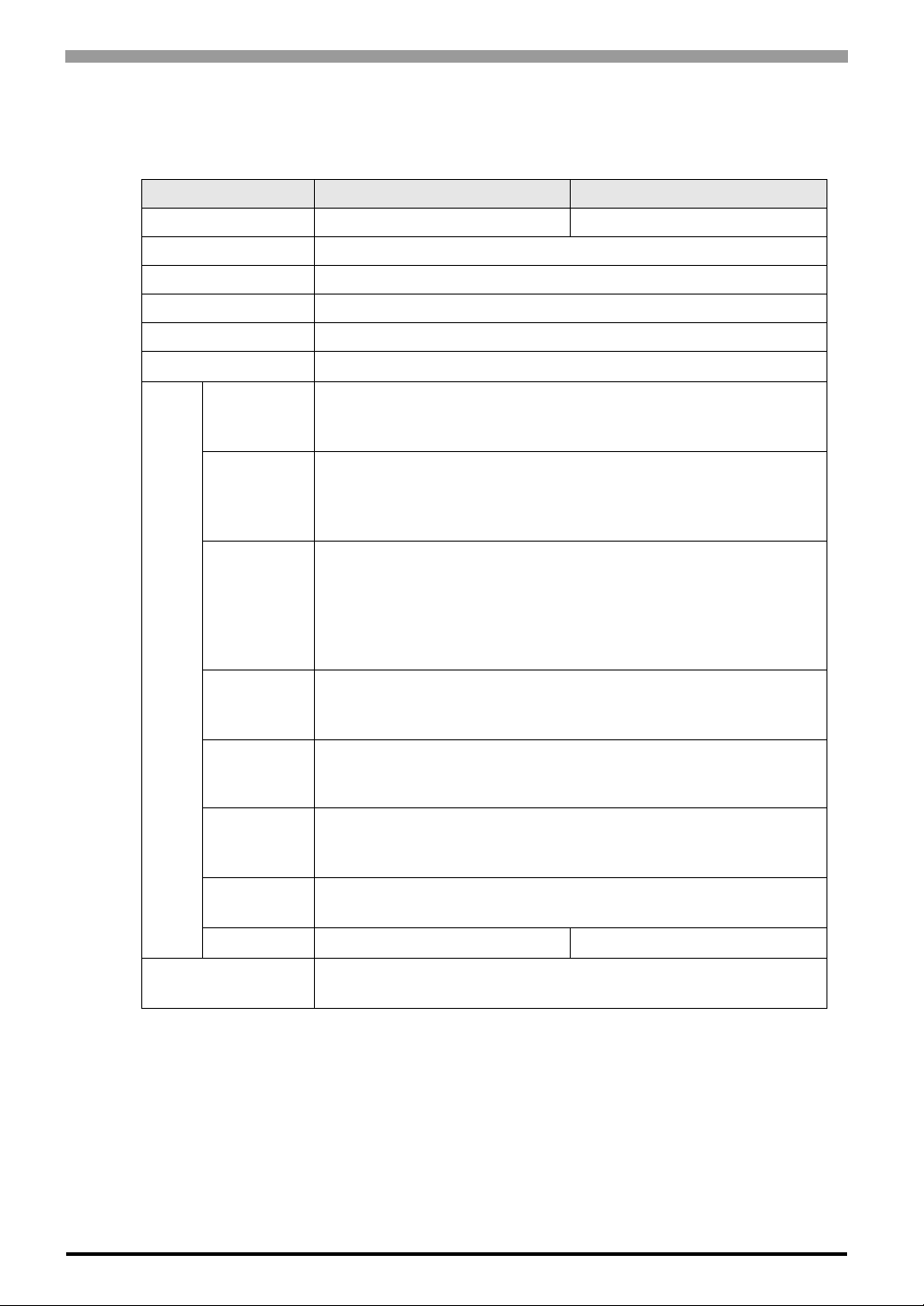
2.2.1 Performance Specifications
CPU Intel Celeron M320 (1.3GHz) Intel ULV CeleronM (600MHz)
L2 Cache Memory 512KB (Built in the CPU)
Main Memory S.O DIMM socket 256 ~ 1GB (PC2700)
BIOS FirstBIOS Embedded Pro (Phoenix Technologies Co.)
Graphics XGA (1024 × 768 dots)
Video Memory
PS-3650A PS-3651A
8 ~ 64MB (UMA method)
Interface
Serial
Interface
Network
Interface
USB
Interface
RAS
Interface
Speaker
Output
Interface
IDE
PCMCIA
PCI
COM1: RS-232C
Corresponding to IEA-232
Connector: D-SUB 9 pin (male) (5V/RI switching available)
Ethernet 2 ports
(Corresponding to IEEE802.3, 10BASE-T/100BASE-TX automatic
switching SIDE)
Connector: Modular Jack (RJ-45)
Front face: USB 1.1 (Low/ Full Speed 12 Mbps) × 1 port
Side face: USB 2.0 (High Speed 480 Mbps) × 4 ports
Connector: USB TYPE-A
Power supply voltage: 5V DC ±5%
Output current : 500mA(max.)
The maximum communication distance: 5m
General Input 2ch (DIN1 can be used as Reset Input),
General Output 2ch
Connector: D-SUB 9 pin (female)
Stereo Speaker output
Connector: Mini Pin Jack
Ultra ATA100
Primary Master: 2.5 inch HD slot
Primary Slave: CF card slot (Type 2)
Corresponding to CARD SUB
(Excluding VIDEO ZOOM, SOUND functions)
PCI Rev. 2.2 (33MHz) None
2-4
Clock Accuracy
*1 The clock, RTC, built in the PS-A has fudge error. The range if the error will be between
+300 ~ -300 sec. / month, depending on the PS-A’s conditions such as lifetime usage or
temperature difference. If you use the PS-A in a system that takes this error seriously, adjust the clock in regular intervals.
*1
± 180 sec. / month (fudge factor by the situation at normal
temperature and power-off)
Page 26
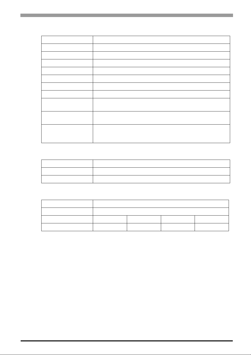
2.2.2 Display
Type TFT Color LCD
Resolution W1,024 x H768 pixels
Dot pitch W0.24mm [0.01in.] x H0.24mm [0.01in.]
Effective Display Area W245.76mm [9.68in.] x H184.32mm [7.26in.]
Color/Shade level 262,144 colors
Backlight CFL (user replaceable)
Brightness control 4 levels of adjustment
Contrast Adjustment None
View Angles
Display Service Life
Backlight Service Life
Chapter 2 Specifications
Horizontal Direction : 120 degrees, Vertical Direction: 100 degrees
(Contrast ratio: CR is 10 or greater, or TYP value)
50,000hrs.
(at 25°C and 65%RH (humidity))
50,000hrs. or more (at ambient temperature 25
operation - period until backlight brightness decreases to 50% or
backlight starts to flicker)
°C and continuous
2.2.3 Touch Panel
Type Resistive Film (analog)
Resolution 1024 x 1024
Service Life 1,000,000 times or more, Sweeping 100,000 times or more
2.2.4 Expansion Slot
Slot Type PCI 2.2 (5V)
Size 174.63mm [6.88in.] × 106.68mm [4.20in.]
Output Voltage DC5V DC12V DC-12V DC3.3V
consumption current 1.5A 0.5A 0.1A 0.5A
2-5
Page 27
PS-3650A / PS-3651A User Manual
2.3 Interface Specifications
This section describes the specifications of each interface of the PS-A Series unit.
• The PS-A unit’s serial port is not isolated. When the host (PLC) unit is also not
isolated, be sure to connect the #5 SG (Signal Ground) terminal to reduce the risk
of damaging the RS-232C circuit.
• Inside the PS-A unit, the SG (Signal Ground) and FG (Frame Ground) terminals
are connected.
• When connecting an external device to the PS-A using the SG terminal, be sure
to check that no short-circuit loop is created when you setup the system.
2.3.1 Serial Interfaces (COM1)
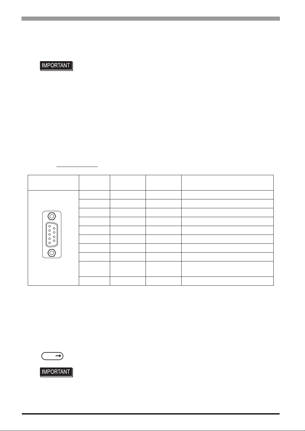
This interface is used to connect an RS-232C (serial) cable. A D-sub 9-pin plug connector is used.
Use #4-40 (Inch Screw)
Pin
Arrangement
5
1
*1 By the switch on the board of the inside of the unit, it is available to change RI/5V .
9
6
fixing clamps to fix the joint of the interspace.
Pin No.
1 CD Input Carrier Detect
2 RD(RXD) Input Receive Data
3 SD(TXD) Output Send Data
4 ER(DTR) Output Data Terminal Ready
5 SG - Signal Ground
6 DR(DSR) Input Data Set Ready
7 RS(RTS) Output Request to Send
8 CS(CTS) Input Send Possible
9 CI(RI)/5V Input
Shell FG - Frame Ground (Common with SG)
Signal
Name
Direction Meaning
Called status display/+5V Output
(Switching available
*1
)
Switch
The RI/5V change switch, corresponding to serial interface, is placed on the board which you opened the fan
cover or the memory slot cover. Refer to the following for more details of how to remove the fan cover or the
2-6
memory slot cover.
SEE
3.3.1 Main Memory Installation (page3-12)
• When you switch RI/5V, you must turn off the power supply for PS-A. Otherwise,
• Prior to the switching action, confirm the interface specification for the othe r sid e
it will cause malfunction.
of the connection. Otherwise, it will cause malfunction.
Page 28
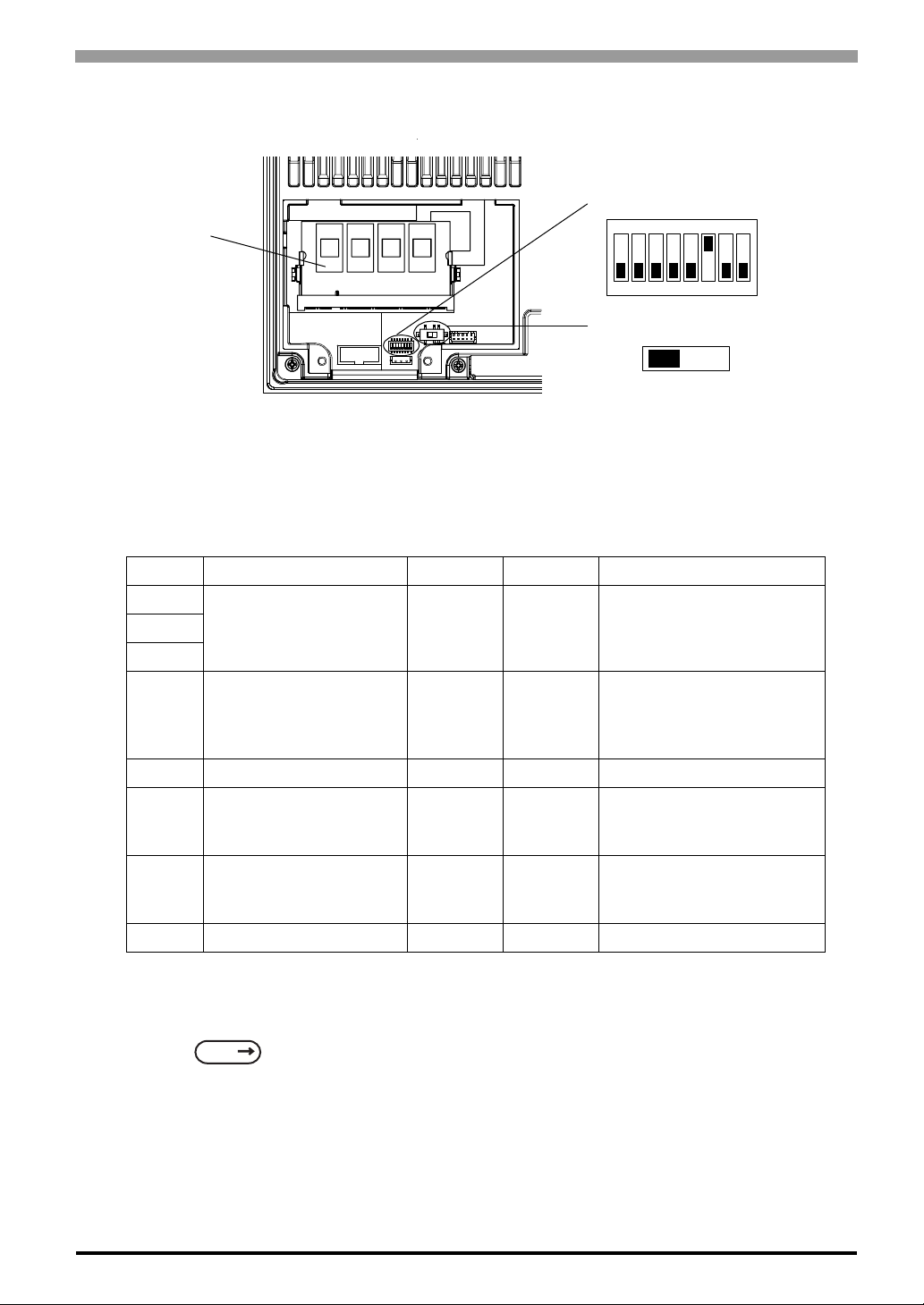
<Magnified image>
Main Memory
Chapter 2 Specifications
DipSW
ON
1 2 3 4 5 6 7 8
RI/5V Changeover Switch
RI
5V
<RI/5V change switch>
The switch can change “RI/5V” for the No.9 pin of a RS-232C. The factory setting is “RI”.
<Dip SW>
SW No. Meaning ON OFF Notes
1
Used for the system. Reserved Reserved The factory setting is “OFF”.2
3
Able to set up an
enabled/disabled state
4
for the front reset
switch.
*1
Disabled Enabled The factory setting is “OFF”.
5 Used for the system. Reserved Reserved The factory setting is “OFF”.
Able to set up an
6
enabled/disabled state
for the front USB.
*2 *3
Enabled Disabled The factory setting is “ON”.
Able to change a Master/
7
Slave setting for CF card
Master Slave The factory setting is “OFF”.
slot.
8 Used for the system. Reserved Reserved The factory setting is “OFF”.
*1 When selected “disabled” , it is impossible to reset the system while the system is running.
However it is possible to enter the reset switch while the system is NOT running (Soft OFF
state). See the following for the Soft OFF State:
SEE
1.1.2 Power Supply (page1-4)
*2 When selected “disabled”, the front USB cannot be used after you turn on the power of the
PS-A.
*3 The front USB port is available for only Windows® 2000 and Windows® XP. Make sure to
disable the function of the setting when other OS used.
2-7
Page 29
PS-3650A / PS-3651A User Manual
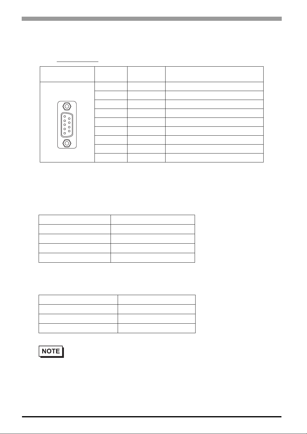
2.3.2 RAS Interface
Types of sockets for D-sub 9 pins are listed below.
Use #4-40 (Inch Screw)
Pin
Arrangement
1
5
*1 DIN1(+) can be used as Remote Reset Input of RAS feature. The factory setting is Gen-
eral Purpose Signal Input.
6
9
fixing clamps to fix the joint of the interspace.
Pin No. Signal Name Meaning
1 +12V 100mA
2 DOUT 0 (+) Data Output 0(+)
3 DOUT 1 (+) Data Output 1(+)
4 DIN 0(+) Data Input 0 (+)
5 DIN 1(+) Data Input 1 (+)
6 GND SG (same as FG)
7 DOUT 0 (-) Data Output 0 (-)
8 DOUT 1 (-) Data Output 1 (-)
9 DINCOM DIN GND Common
*1
General Input (DIN 0, 1)
INPUT VOL TAGE RANGE DC12V to 24V
INPUT CURRENT Below 10mA
INNER RESISTOR 3.6KΩ
INSULATION VOLTAGE Below AC500V
INSULATION Photocoupler
General Output (DOUT 0, 1)
OUTPUT VOLTAGE RANGE DC24V
OUTPUT CURRENT Below 120mA
INSULATION VOLTAGE Below AC500V
INSULATION Photocoupler
• For the circuit diagram, refer to "6.1.2 RAS Feature Details " .
2-8
Page 30
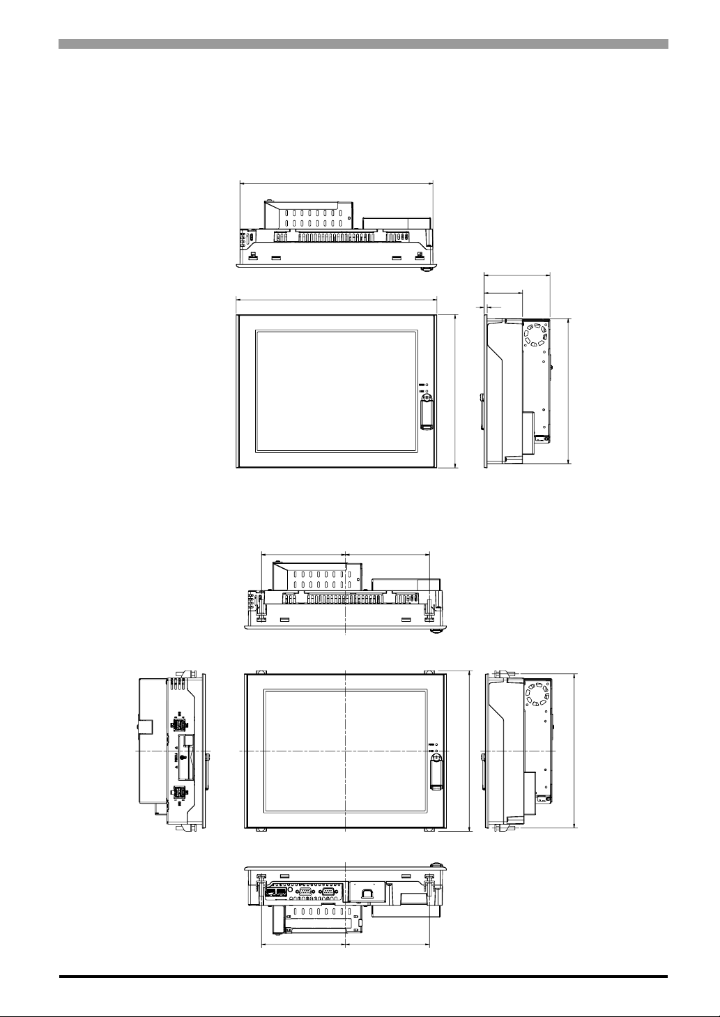
2.4 Dimensions
The following dimensions apply to PS-3650A/PS-3651A units.
2.4.1 PS-3650A External Dimensions
Unit: mm [in.]
301[11.85]
Chapter 2 Specifications
Top
313[12.32]
Front
Dimensions with installation fasteners
130[5.12]
Top
130[5.12]
239[9.41]
103[4.06]
60[2.36]
5[0.20]
227[8.94]
side
side
Front
Bottom
249 [9.80]
side
130[5.12]130[5.12]
239[9.41]
2-9
Page 31
PS-3650A / PS-3651A User Manual
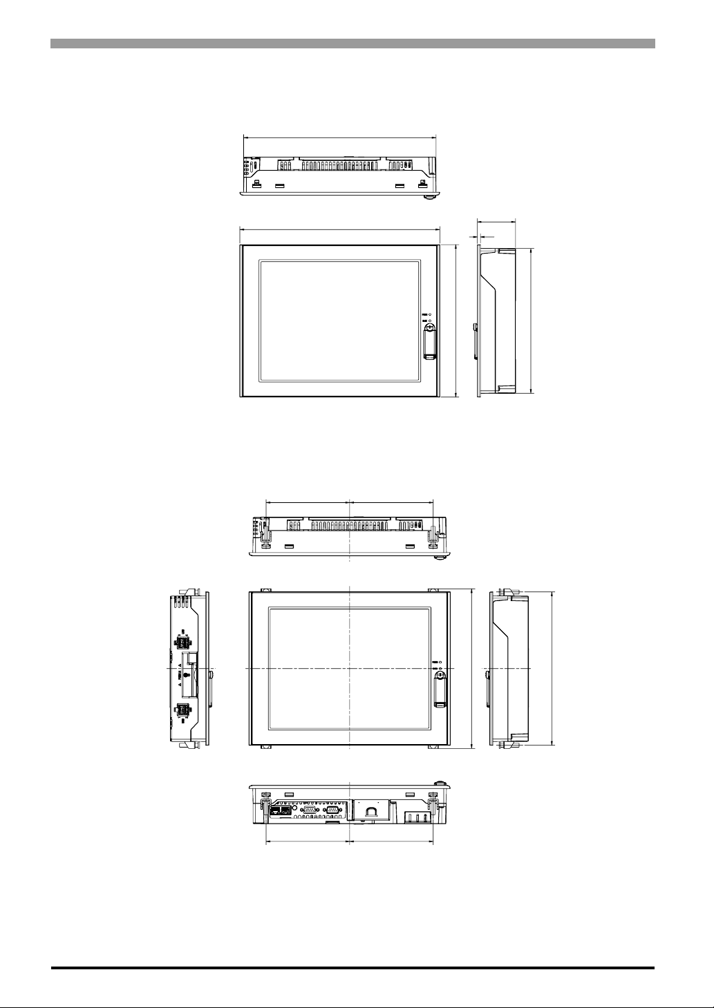
2.4.2 PS-3651A External Dimensions
Unit: mm [in.]
301[11.85]
Top
313[12.32]
Front
Dimensions with installation fasteners
Top
60[2.36]
5[0.20]
239[9.41]
side
130[5.12]130[5.12]
227[8.94]
2-10
side
130[5.12]
Front
Bottom
130[5.12]
249[9.80]
239[9.41]
side
Page 32
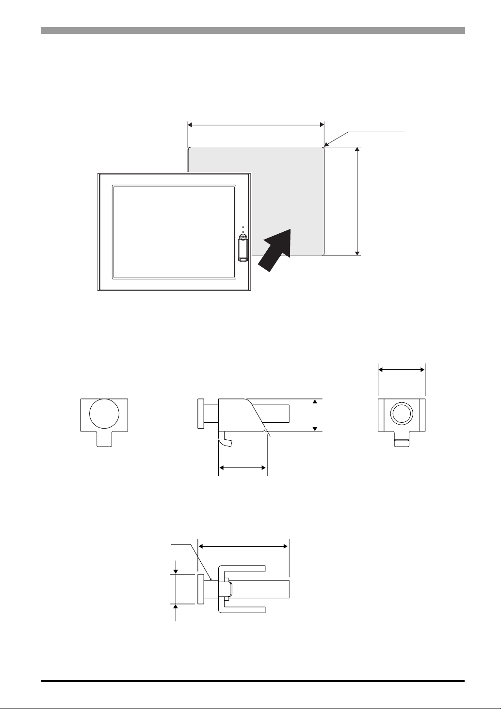
2.4.3 Panel Cut Dimensions
Panel cut dimensions for both PS-3650A and PS-3651A are the same.
Unit: mm [in.]
301.5 [11.87 ]
+1
-0
+0.04
-0
Chapter 2 Specifications
under 4-R3
-0
+0.04
-0
+1
227.5 [ 8.96 ]
2.4.4 Installation Fasteners
Unit: mm [in.]
M6
∅10[0.39]
16 [0.63]
11[0.43]
16.6 [0.65]
31 [1.22]
2-11
Page 33

PS-3650A / PS-3651A User Manual
2.4.5 Dimensions attached RS-232C/RS-485 exchangeable unit
PS-3650A
Unit: mm [in.] (Except for protrudent objects and cable parts)
55[2.17]
50.5[1.99]
3 [0.12]
60[2.36]
PS-3651A
Unit: mm [in.] (Except for protrudent objects and cable parts)
55[2.17]
50.5[1.99]
15.5[0.61]
60[2.36] 3 [0.12]
2-12
Page 34

3 Hardware
Installation
1. Installation
2. Wiring Precautions
3. Peripheral Devices Installation
3-1
Page 35
PS-3650A / PS-3651A User Manual
3.1 Installation
This section describes the procedures and precautions for installing the PS-A unit.
3.1.1 Installation Procedures
Follow the steps given below when installing the PS-A.
Check the Installation Gasket’s Seating
It is strongly recommended that you use the installation gasket, since it absorbs vibration in addition to
repelling water.
For the procedure for attaching the installation gasket, refer to the following.
SEE
7.4 Replacing the Installation Gasket (page7-6)
• Before installing the PS-A into a cabinet or panel, check that the installation gasket
is securely attached to the unit.
• A gasket which has been used for a long period of time may have scratches or dirt
on it, and could have lost much of its dust and drip resistance. Be sure to change
the gasket periodically (or when scratches or dirt become visible).
3-2
Page 36
Chapter 3 Hardware Installation
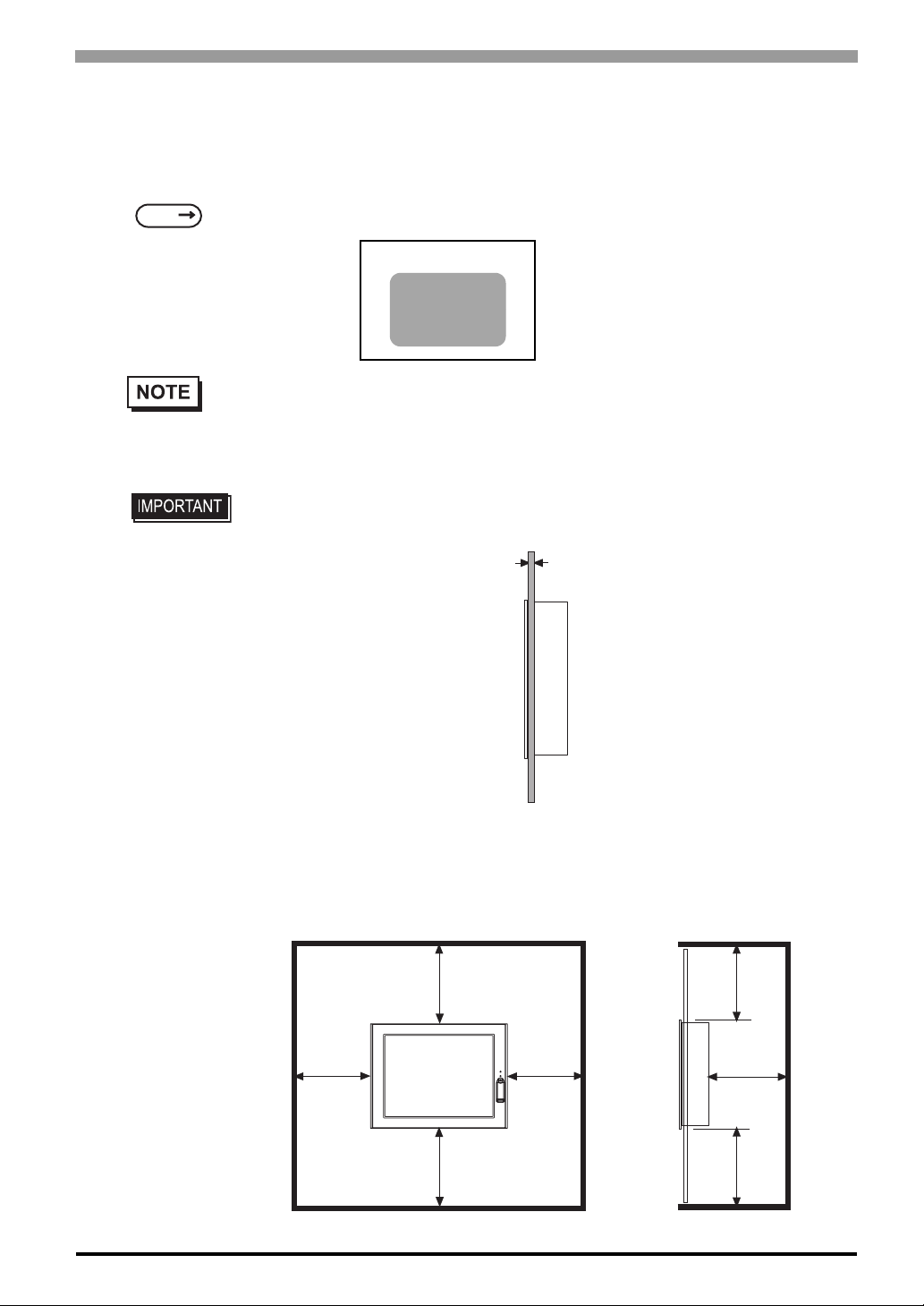
Creating a Panel Cut
Create the correct sized opening required to install the PS-A, using the installation dimensions given.
The installation gasket and the installation fasteners are required when installing the PS-A.
SEE
2.4.3 Panel Cut Dimensions (page2-11)
Panel
Panel Cut
Area
• Check that the installation panel or cabinet’s surface is flat, in good condition and has no jagged
edges. Also, if desired, metal reinforcing strips can be attached to the inside of the panel, near
the Panel Cut, to increase the panel’s strength.
• Panel thickness should be from 1.6mm [0.06 in.] to 10.0mm [0.39 in.]. Decide the
panel’s thickness based on the level of panel strength required.
1.6mm [0.06 in.] to 10.0mm [0.39 in.]
• For easier maintenance, operation, and improved ventilation, be sure to install
the PS-A at least 50 mm [1.97 in.] away from adjacent structures and other equipment.
Unit: mm [in.]
50
[1.97]
50
[1.97]
50
[1.97]
50
[1.97]
50
[1.97]
50
[1.97]
50
[1.97]
3-3
Page 37
PS-3650A / PS-3651A User Manual
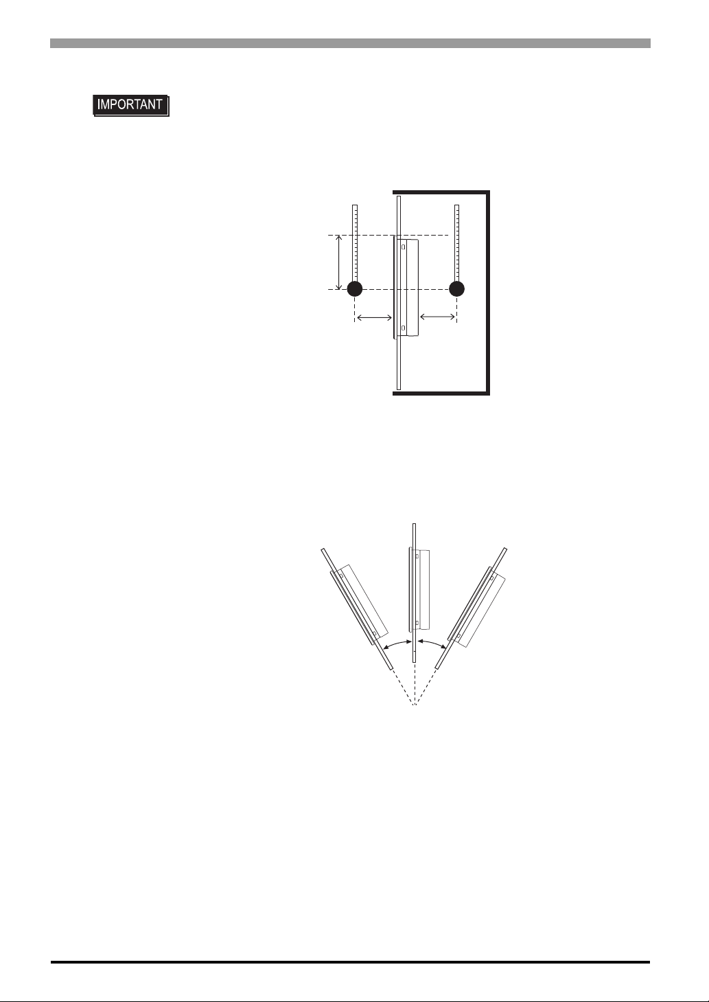
• Be sure that the ambient operation temperature and the ambient humidity are within
their designated ranges. When installing the PS-A on the panel of a cabinet or
enclosure, “Ambient operation temperature” indicates both the panel face and
cabinet or enclosure’s internal temperature.
Unit: mm [in.]
50 [1.97]
30[1.18]
Panel
face
• Be sure that heat from surrounding equipment does not cause the PS-A to exceed
its standard operating temperature.
• When installing the PS-A in a slanted panel, the panel face should not incline more
than 30°.
30[1.18]
Inside of the
enclosure
30° or less
3-4
• When installing the PS-A in a slanted panel, and the panel face inclines more than
30°, the ambient temperature must not exceed 40°C. You may need to use forced
air cooling (fan, A/C) to ensure the ambient operating temperature is 40°C or below.
• The PS-A Series unit does not support longitudinal mounting.
Page 38
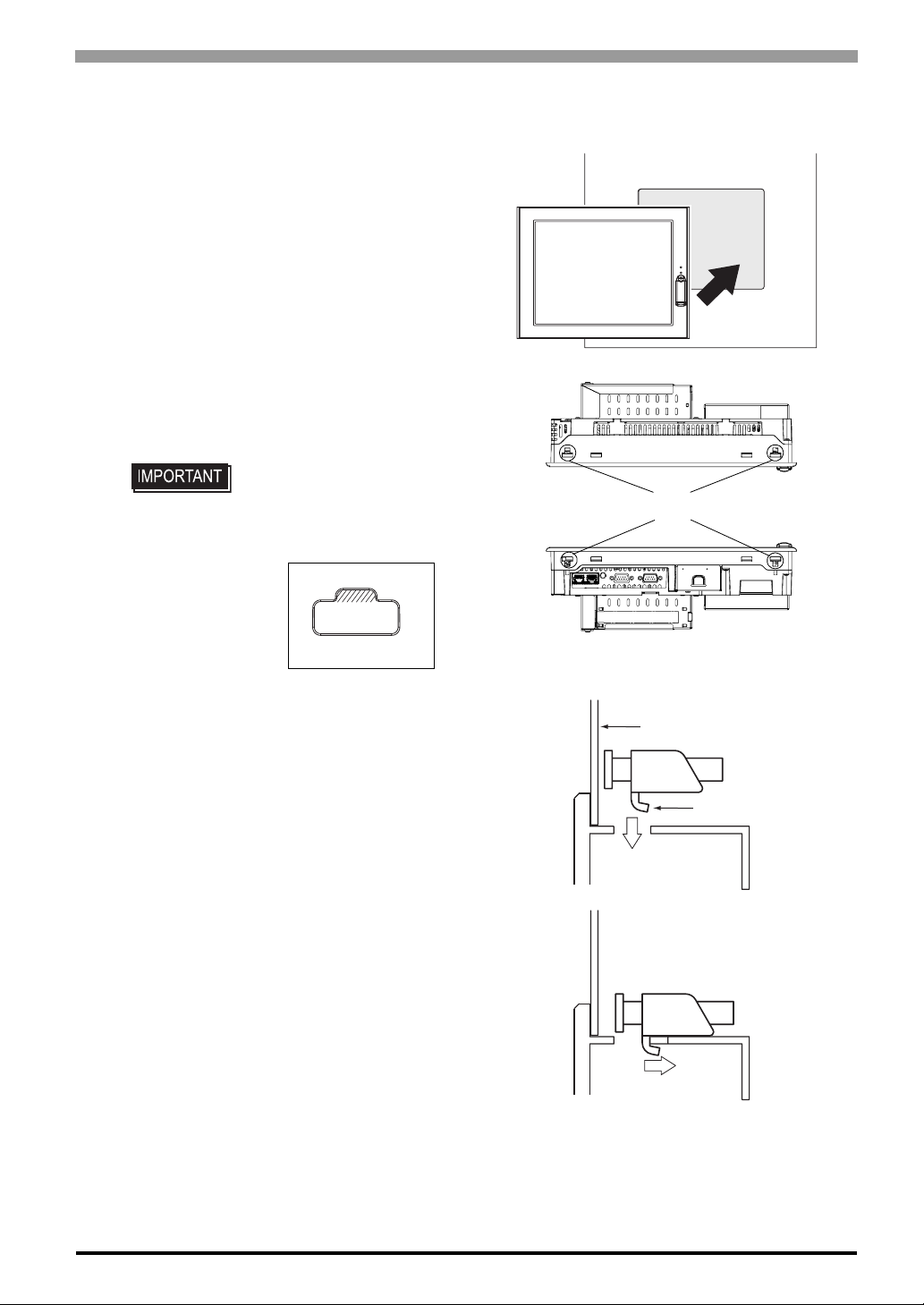
Installing the PS-A
(1) Insert the PS-A into the panel cut, as shown.
(2) Insert the installation fasteners into the PS-A
insertion slots, at the top and bottom of the
unit. (total: 4 slots)
• Insert each installation
Chapter 3 Hardware Installation
fastener securely into the
slot’s recess (shaded area).
•
(3) Insert each of the fasteners shown below.
Be sure to pull the fastener back until it is
flush with the rear of the attachment hole.
Slots
Installation Panel
Hook
3-5
Page 39
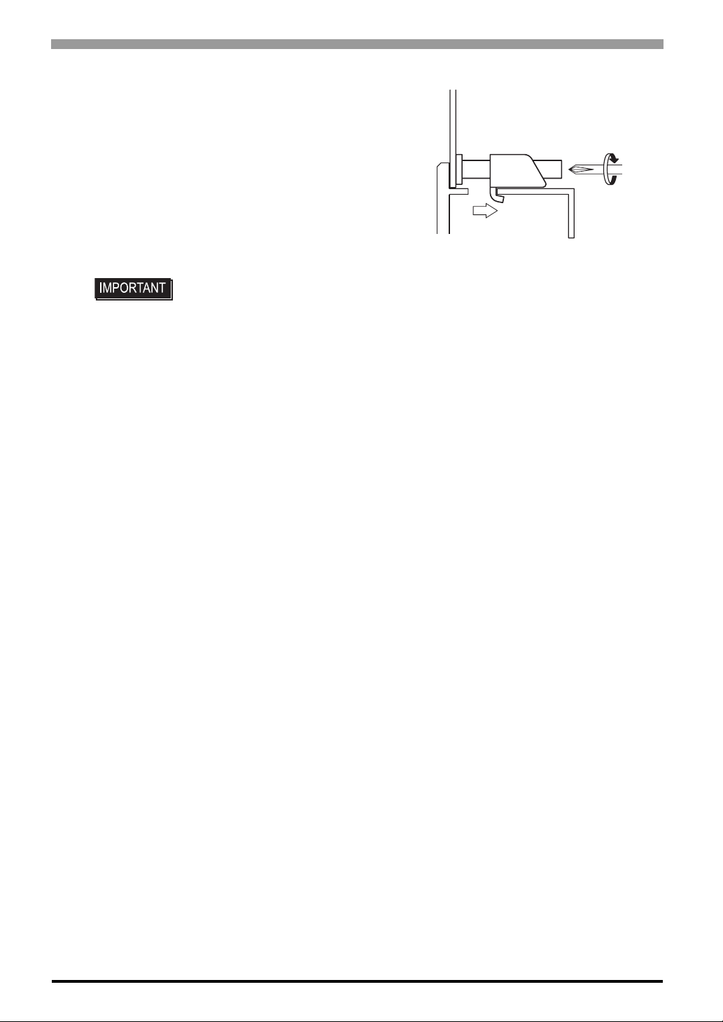
PS-3650A / PS-3651A User Manual
(4) Use a Phillips screwdriver to tighten each
fastener screw and secure the PS-A in
place.
• Tightening th e screws with too much for ce can damage the PS-A unit’s plastic case.
• For the moisture resistance effect, the torque required to tighten these screws is 0.5
•m.
N
3-6
Page 40
3.2 Wiring Precautions
This section describes the procedures and precautions to install the PS-A unit.
3.2.1 Connecting the Power Cord
To avoid an electric shock, prior to connecting the PS-A unit’s power cord terminals to the
power terminal block, confirm that the PS-A unit’s power supply is completely turned OFF,
via a breaker, or similar unit.
The PS-A units is designed to use AC100V to AC240V input. Supplying a power voltage
other than that specified will damage the power source and the PS-A unit.
When the FG terminal is connected, be sure the wire is grounded to avoid an electric shock
at breakdown.
• The power cord included in the package, is designed only for AC100V use. Under
Chapter 3 Hardware Installation
other voltage situation, you should use a different cord in conformity with the
voltage.
• When the FG terminal is connected, be sure the wire is grounded. Not grounding
the PS-A unit will result in excess noise and vibration.
• The SG and FG terminals are connected internally in the PS-A unit.
• When connecting the SG wire to another device, be sure that the design of the
system/connection does not produce a shorting loop.
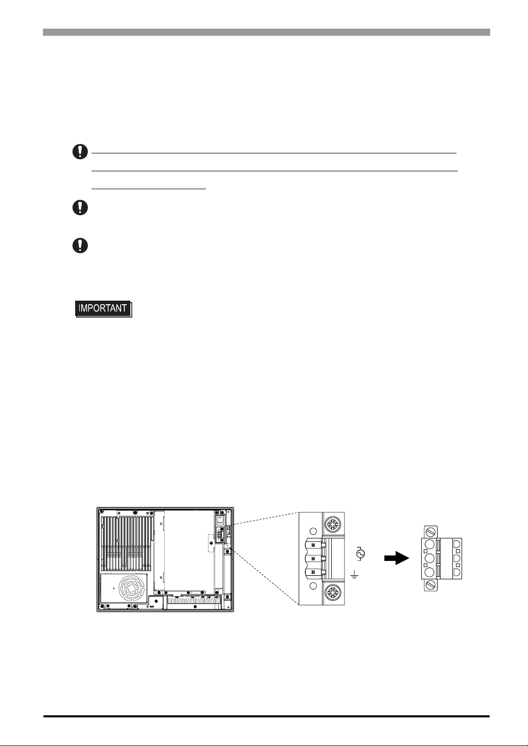
Connect the power cable to the power plug attached to the PS-A unit. The power plug is removable from the
Power Connector on the PS-A unit.
Removable
L
N
FG
PS-A Rear
Power Connector
Power Plug
3-7
Page 41
PS-3650A / PS-3651A User Manual
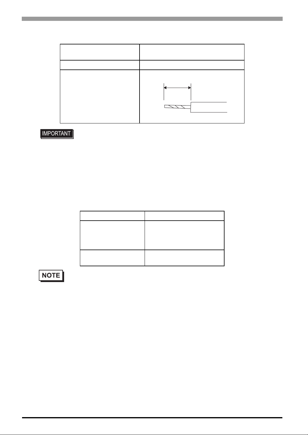
Power Cable specifications
Power Cable Size
Type of Cable Core Single or Strand Wire
Cable Core Length
• Use copper conductors only.
• When using the Strand Wire, if the Conductor's end (individual) wires are not twisted
correctly, the end wires may either short against each other, or against an electrode.
Wiring
0.75 to 2.5mm² [0.0009 to 0.0097inch
(18 to12AWG)
10mm [0.39in.]
2
]
When connecting the Power Cord, use the following items when performing wiring. (Items are made by
Phoenix Contact.)
• The power supply plug FKC2.5/3-STF-5.08 is manufactured by Phoenix Contact.
*1
Recommended Tool SZS 0.6X3.5 (1205053)
AI 0.75-10GY (3201288)
Recommended Pin
Terminals
Recommended Pin
Terminal Crimp Tool
AI 1-10RD (3200182)
AI 1.5-10BK (3200195)
AI 2.5-12BUK (3200962)
CRIMPFOX ZA3 (1201882)
3-8
*1 For further details, please contact your local Phoenix Contact distributor.
Page 42
Chapter 3 Hardware Installation
Connecting the Power Cord
• To prevent the possibility of a terminal short, use a pin terminal that has an
insulating sleeve.
• The temperature rating of field installed conductors : 75°C only.
(1) Confirm that the power cord is unplugged from the power supply.
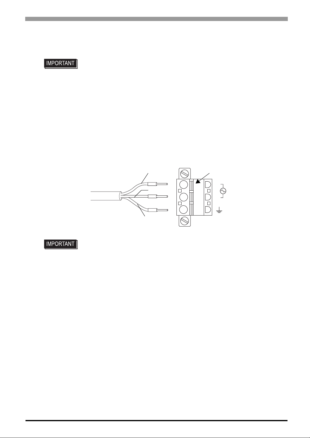
(2) Open the cable attachment holes of the Power Plug. There are Open Buttons next to the holes corre-
sponding to each of cable cores. Push that button with a straight slot screwdriver etc., and the button
opens.
(3) Insert the crimp-type pin terminal of the cable core completely into the hole with the Open Button
pushed. When stopping pushing the button, the hole shuts and the cable is fixed.
Open ButtonBlack
White
L
N
(AC Power Cord)
Green/Yellow
• Check the color of each cable core, first. Then connect it to each hole correctly.
(4) Insert the power plug into the socket of the PS-A, then screw both of the screw to fix. The torque
required to tighten these screws is 0.5 to 0.6•m.
FG
3-9
Page 43
PS-3650A / PS-3651A User Manual
3.2.2 Connecting the Power Supply
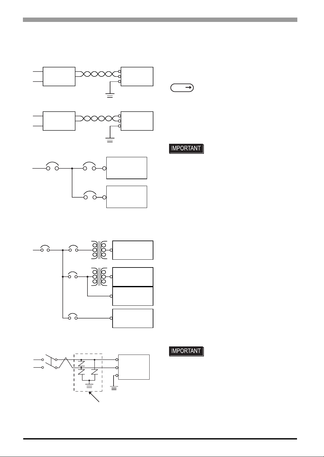
This section describes the precautions for supplying a power voltage.
Constant
Voltage
Transformer
Insulating
Transformer
Main Power
Main
Power
Twisted-pair cord
Twisted-pair cord
PS-A Power
Power
Input/Output
PS-A
Power
T1
T2
Power
Input/
Output
Main
Circuit
PS-A Unit
FG
PS-A Unit
FG
PS-A Unit
Input/Output
Unit
PS-A Unit
Input/Output
Unit
Input/Output
Unit
Operation
Unit
• If the supplied voltage exceeds the PS-A unit's range,
connect a constant voltage transformer.
SEE
• For between the line and ground or between the lines,
select a power supply that is low in noise. If there is an
excess amount of noise, connect a insulating transformer.
• When supplying power to the PS-A unit, please
separate the input/output and operation unit lines, as
shown.
• To increase the noise resistance quality of the power
cord, it is recommended to attach a ferrite core to the
power cord.
• The power supply cable must not be bundled or
positioned close to main circuit lines (high voltage,
high current), or input/output signal lines.
• Connect a lightening surge absorber, as shown in the
diagram, to deal with power surges.
• To avoid excess noise, make the power cord as short as
possible.
2.1.1 Electrical (page2-2)
• Use constant voltage and
insulating transformers with
capacities of 200VA or more.
3-10
E1
PS-A Unit
FG
E2
Lightening Surge
Absorber
• Be sure to ground the surge
absorber (E1) separately from
the PS-A unit (E2).
• Select a surge absorber that has
a maximum circuit voltage
greater than that of the peak
voltage of the power supply.
Page 44
3.2.3 Grounding
This section describes the precautions for grounding the PS-A unit.
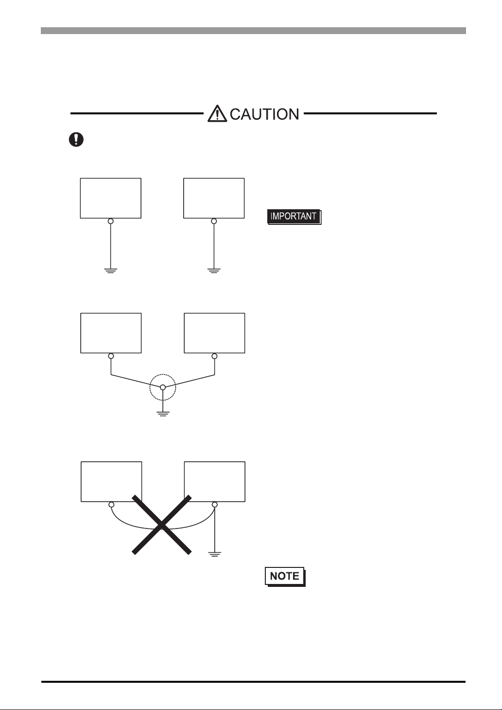
Do not use common grounding, since it can lead to an accident or machine breakdown.
Chapter 3 Hardware Installation
(a) Exclusive Grounding (BEST)
PS-A Unit Other
(b) Common Grounding (OK)
PS-A Unit Other
(c)Common Grounding (Not OK)
Equipment
Equipment
• When supplying power to the PS-A unit, be sure to
separate the input/output and power lines, as shown.
[diagram (a)]
• Check that the grounding
resistance is 100Ω or less.
• FG and SG terminals are
internally connected in the PS-A.
When connecting an external
device to the PS-A using the SG
terminal, be sure to check that
no short-circuit loop is created
when you setup the system.
• The grounding wire should have
a cross sectional area of 2mm
[0.0062inch2] or greater. Create
the connection point as close to
the PS-A unit as possible, and
make the wire as short, as
2
PS-A Unit Other
Equipment
3.2.4 I/O Signal Line Placement
• Input and output signal lines must be separated from the power control cables for operating circuits.
• If this is not possible, use a shielded cable and ground the edge of the shield.
possible. When using a long
grounding wire, replace the thin
wire with a thicker wire, and
place it in a duct.
• If exclusive grounding is not possible, use a common
connection point. [diagram (b)]
• If the equipment does not function
properly when grounded, disconnect
the ground wire from the FG terminal.
3-11
Page 45
PS-3650A / PS-3651A User Manual
3.3 P eripheral Devices Installation
A wide variety of optional units, DIM module, CF cards, manufactured by Pro-face and commercial
Expansion boards (PCI bus compatible board), PCMCIA (PC cards) can be used with the PS-A. (Expansion
boards are used only for PS-3650A.)
When installing the optional units, refer to each unit's "Installation Guide".
Be sure to confirm that power is not supplied to the PS-A unit before installing or removing
any optional units, DIM module, CF cards, or Expansion boards (PCI boards). Failure to do
so can result in an electric shock.
• If the PS-A unit is in the Soft OFF Status, power is supplied to a part of circuits
even when no screen is displayed.Be sure to confirm that a power cable is not
connected before installing or removing peripheral equipment.
• When removing or replacing screws, be careful that they do not fall inside the PSA unit's chassis.
• When installing the PS-A unit, or when attaching an optional item to the PS-A
unit, do not hold the PS-A unit’s rear-face fan cover while performing the work.
Doing so may damage the fan cover or cause the cover to fall off.
3.3.1 Main Memory Installation
PS-3650A
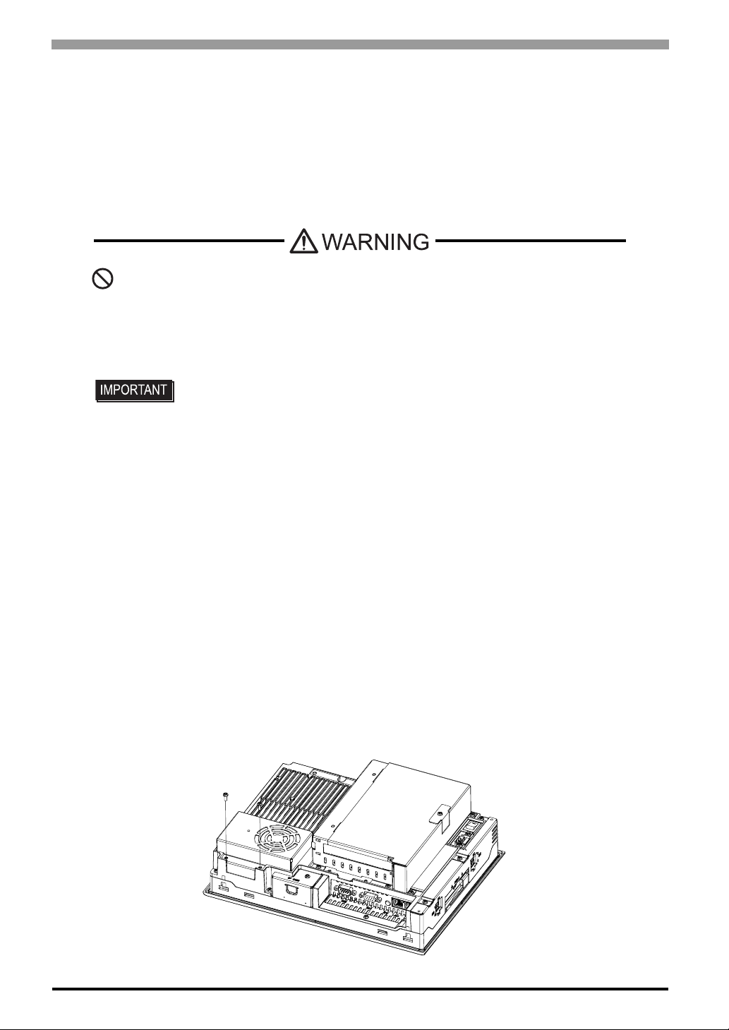
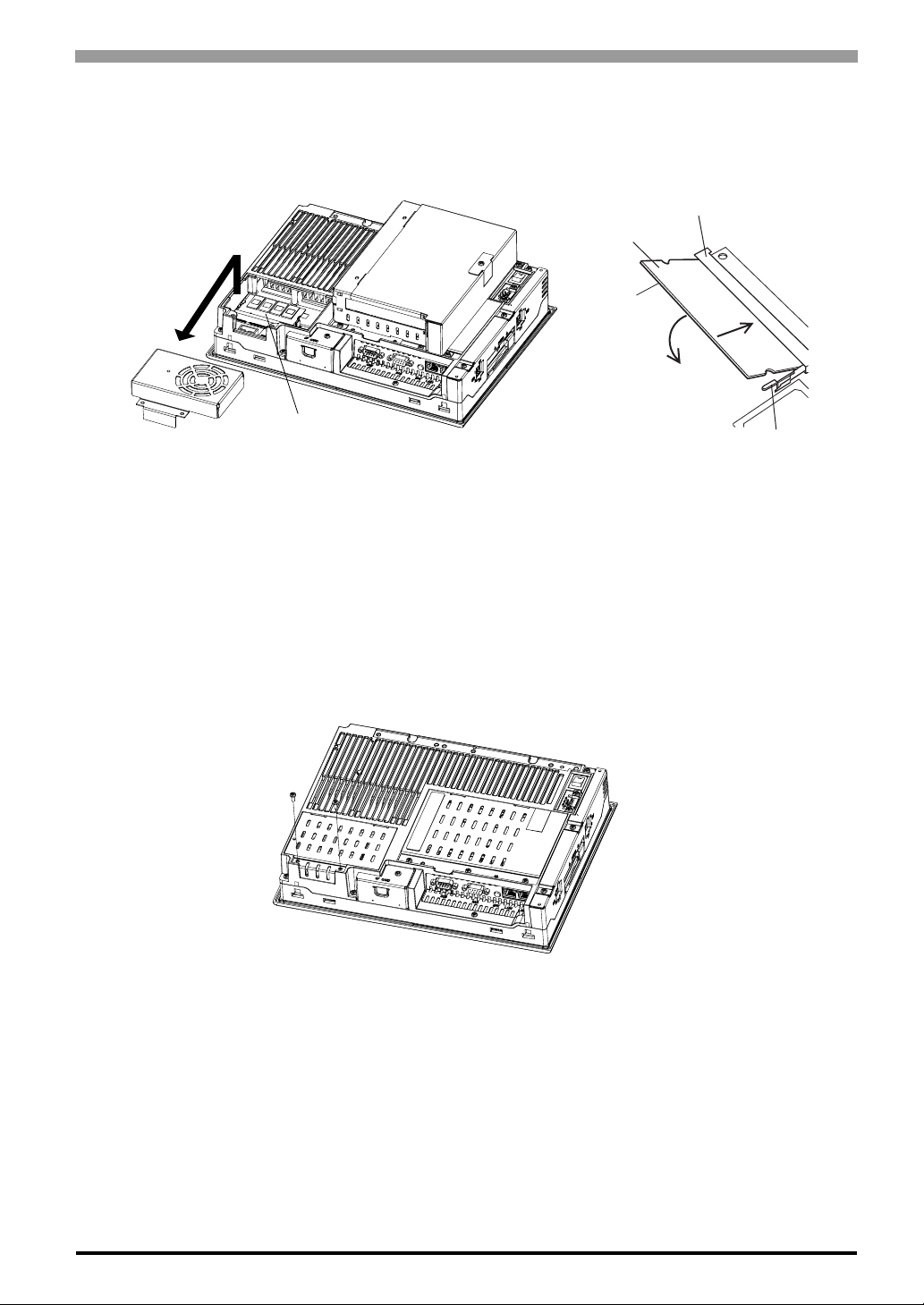
(1) Turn OFF the power switch of the PS-A and remove the power cable. Place the PS-A on a flat, level sur-
face facing the display face downwards.
(2) Unscrew the screws (2) as you see on the following figure, then remove the cooling fan.
3-12
Page 46
Chapter 3 Hardware Installation
r
(3) Install the main memory where the following figure shows. Insert the DIM module, which is an optional
product, into the connector completely in an oblique direction, then press it downward until it is locked
into the stopper.
Connector
Main Memory
1
2
Main Memory (DIM Module)
(4) Place back the cooling fan and fix with two screws. The torque required to tighten these screws is 0.5 to
0.6N•m.
Stoppe
PS-3651A
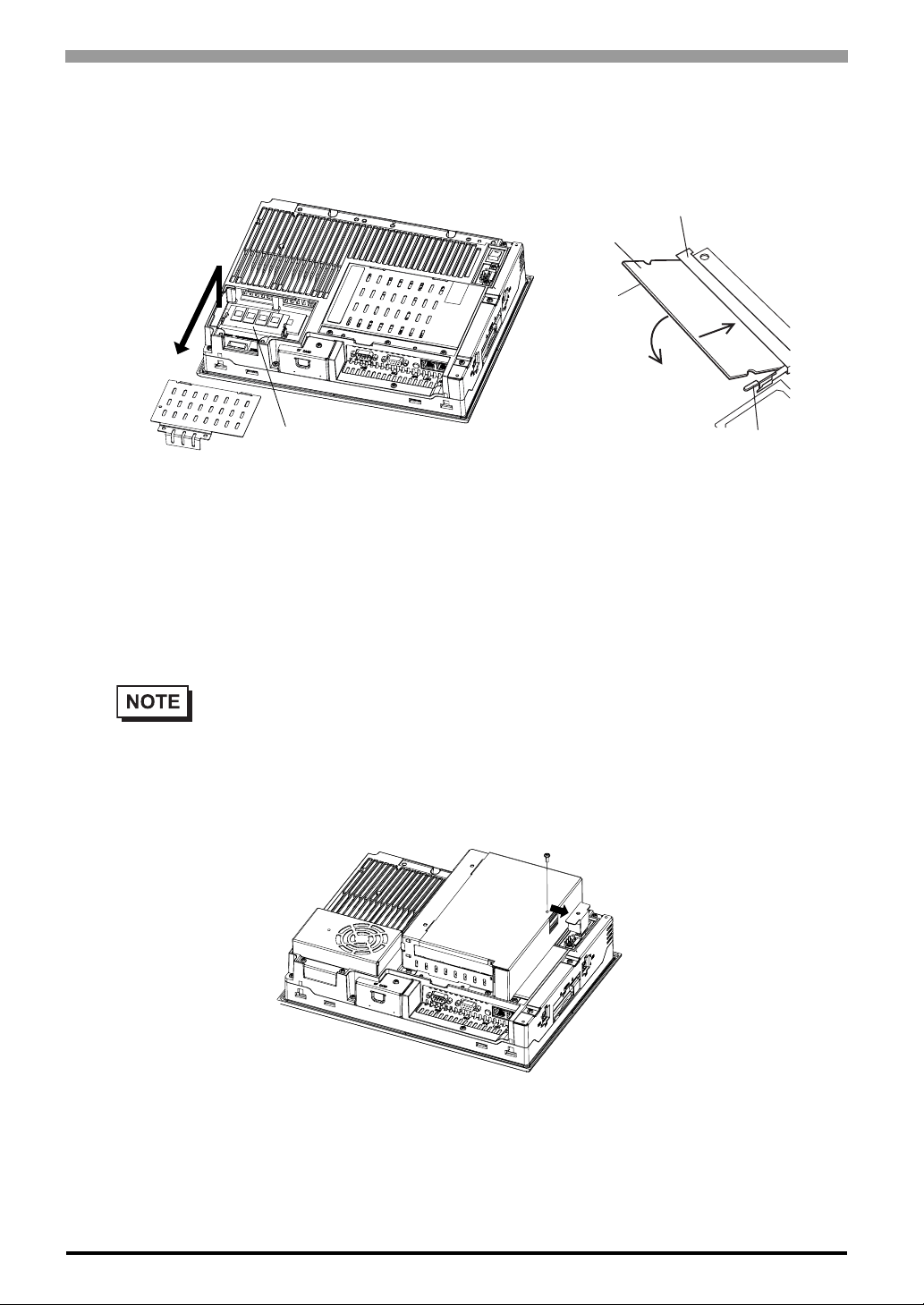
(1) Turn OFF the power switch of the PS-A and remove the power cable. Place the PS-A on a flat, level sur-
face facing the display face downwards.
(2) Unscrew the screws (2) as you see on the following figure, then remove the Memory slot cover.
3-13
Page 47
PS-3650A / PS-3651A User Manual
r
(3) Install the main memory where the following figure shows. Insert the DIM module, which is an optional
product, into the connector completely in an oblique direction, then press it downward until it is locked
into the stopper.
Connector
Main Memory
1
2
Main Memory (DIM Module)
(4) Place back the Memory slot cover and fix with two screws. The torque required to tighten these screws
is 0.5 to 0.6N•m.
3.3.2 PCI Board Installation
A PCI board, which is sold on the market, can be installed on PS-3650A.
• The maximum size allowed for a PCI board is 174.63mm [6.88in.] × 106.68mm [4.2in.].
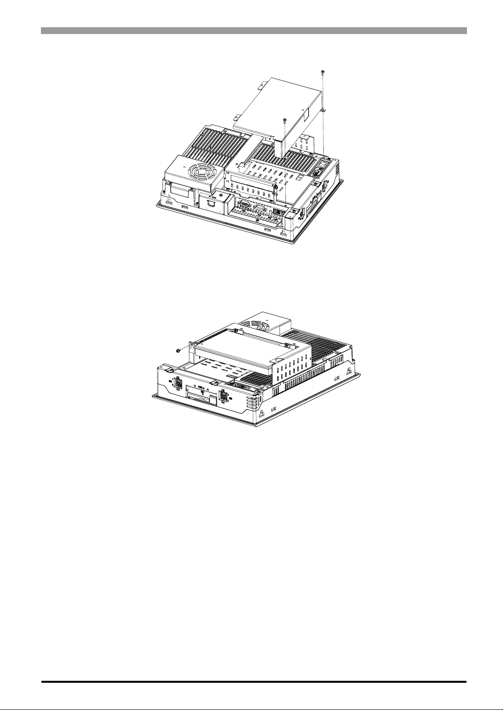
(1) Turn OFF the power switch of the PS-A and remove the power cable. Place the PS-A on a flat, level sur-
face facing the display face downwards
(2) Unscrew a screw of the expansion board support and remove the expansion board support.
Stoppe
3-14
Page 48
Chapter 3 Hardware Installation
(3) Unscrew the expansion board cover’s screws (2) and remove the expansion board cover.
(4) Unscrew a screw of the blank panel and take out the blank panel.
(5) Insert the PCI board into the expansion board connector and place back the screw to fix the PCI board.
The torque required to tighten a screw is 0.5 to 0.6N•m.
PCI Board
(6) Place back both of the expansion board cover and expansion board support. The torque required to
tighten each of the screws is 0.5 to 0.6N•m.
3-15
Page 49
PS-3650A / PS-3651A User Manual
3.3.3 PCMCIA (PC Card) Installation/Removal
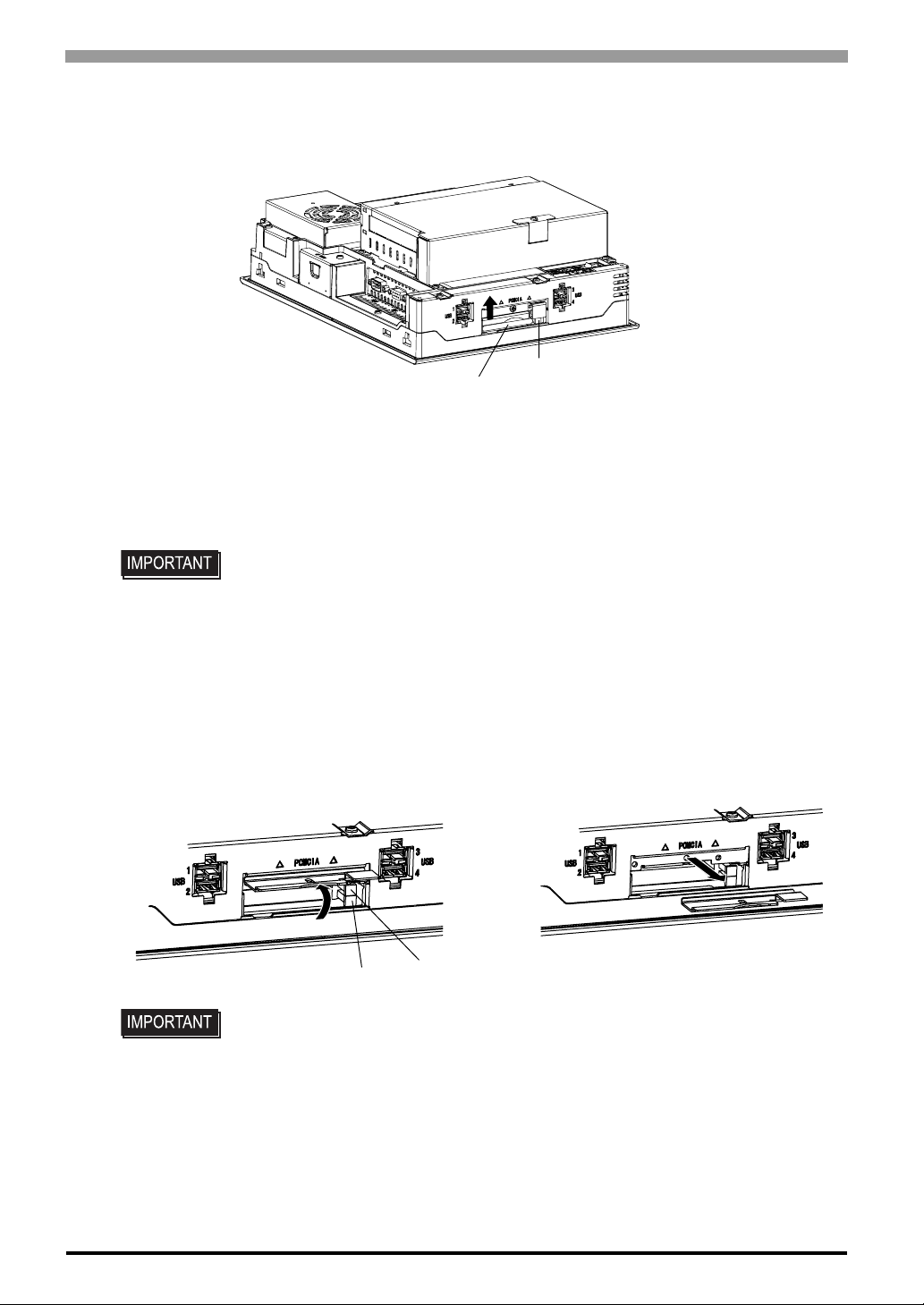
(1) Slacken a screw of PCMCIA slot on the side of the PS-A unit to move the cover.
PC Card
(2) Press the eject button twice to remove the PC Card from the PCMCIA connec tor. (Pressing the eject but-
ton once causes its tip to come out. Pressing the eject button the second ejects the PC Card from the
PCMCIA slot.)
(3) Place back the PCMCIA slot cover and tighten a screw.
• When using a PC Card with a cable attached, Pro-face recommends you use a clamp or
Eject Button
other type of device to prevent vibration from possibly dislodging the cable.
• When energizing to PS-A, be sure to stop the PS-A unit PC Card’s driver prior to removing the PC Card. A failure to stop this driver may result in damage to either th e PC Card,
®
the PC Card's data, or may cause Windows
for stopping the PC Card’s driver, please refer to your OS' User Manual.
To install a PC Card Type III, unscrew the PCMCIA slot cover’s screw and remove the cover as shown below.
A
• Install the PC Card in the slot on the display side (A in the illustration). The slot on
the rear side (B in the illustration) does not support a PC card.
• Please keep the removed PCMCIA slot cover and screw with care.
B
to hang up. For information on the procedure
3-16
Page 50
3.3.4 CF Card Insertion/Removal
When using the PS-A Unit and a CF Card, observe the following precautions:
Prior to inserting or removing a CF Card, be sure to confirm that the PS-A unit is turned
OFF. If you do not, CF Card internal data may be damaged or lost or the OS may stop.
While a CF Card is being accessed (Status LED: Blinking in green), NEVER turn OFF or
reset the PS-A, or insert or remove the CF Card. If you do not, CF Card internal data may
be damaged or lost.
Prior to inserting a CF Card, familiarize yourself with the CF Card’s front and rear face
orientation, as well as the CF Card connector’s position. If the CF Card is not correctly
positioned when it is inserted into the Multi Unit, the CF Card’s internal data, CF Card and
the PS-A unit may be damaged or broken.
Be sure to use only CF Cards manufactured by the Pro-face. The CF Card’s internal data
Chapter 3 Hardware Installation
may be damaged when using another manufacturer’s CF Card.
Once PS-A data is lost, it cannot be recovered. Since accidental data loss can occur at any
time, be sure to back up all PS-A screen and CF Card data regularly.
Be sure to follow the instructions given below to prevent the CF Card’s internal data from
being destroyed or a CF Card malfunction from occurring:
• DO NOT bend the CF Card.
• DO NOT drop or strike the CF Card against another object.
• Keep the CF Card dry.
• DO NOT touch the CF Card connectors.
• DO NOT disassemble or modify the CF Card.
3-17
Page 51
PS-3650A / PS-3651A User Manual
Inserting the CF Card
Use the following steps to insert the CF Card in the PS-A.
(1) Confirm that the PS-A is turned OFF.
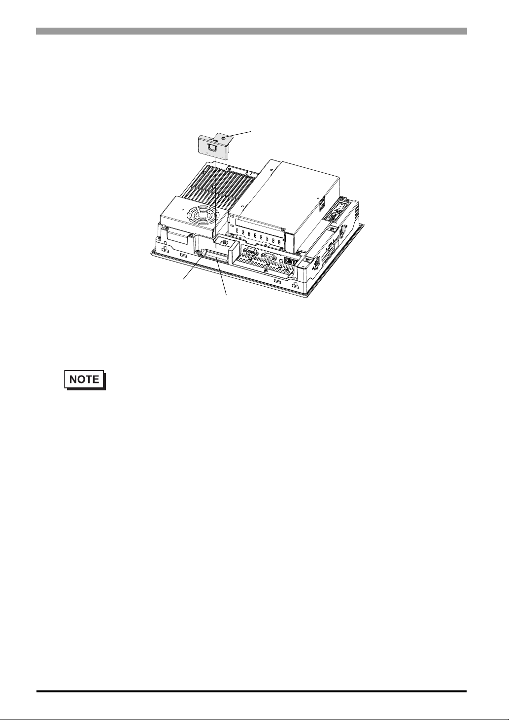
(2) Slacken a screw of the CF card cover and remove the CF card cover.
Eject Button
Screw
CF Card
(3) Confirm two sides of the CF card and insert the CF card in the CF card slot. Push the eject button com-
pletely until the eject butto n is pushed forward.
(4) Install the CF Card cover and fix it with a screw.
• Make sure that the CF card cover is closed when accessing the CF card.
• The torque required to tighten a screw is 0.5 to 0.6N•m.
Removing the CF Card
Confirm that the PS-A is turned OFF. Then, remove the CF card cover, press the eject button and carefully
remove the CF card. After removing the CF card, be sure to place back the CF card cover and fix the cover
with a screw.
Backup of CF Card
The CF Card has a data overwrite limit of approximately 100,000 times. Therefore, be sure to back up all CF
card data regularly to another storage media. (100,000 times assumes the overwriting of 500KB of data in
DOS format.)
< If your PC is equipped with a PC Card Slot >
(1) Install the CF card into a CF Card Adapter (GP077-CFAD10) and insert it into a PC card slot of a per-
3-18
sonal computer .
(2) Save the data of the CF Card with your personal computer.
Page 52
3.3.5 USB Holder Attachment/Removal
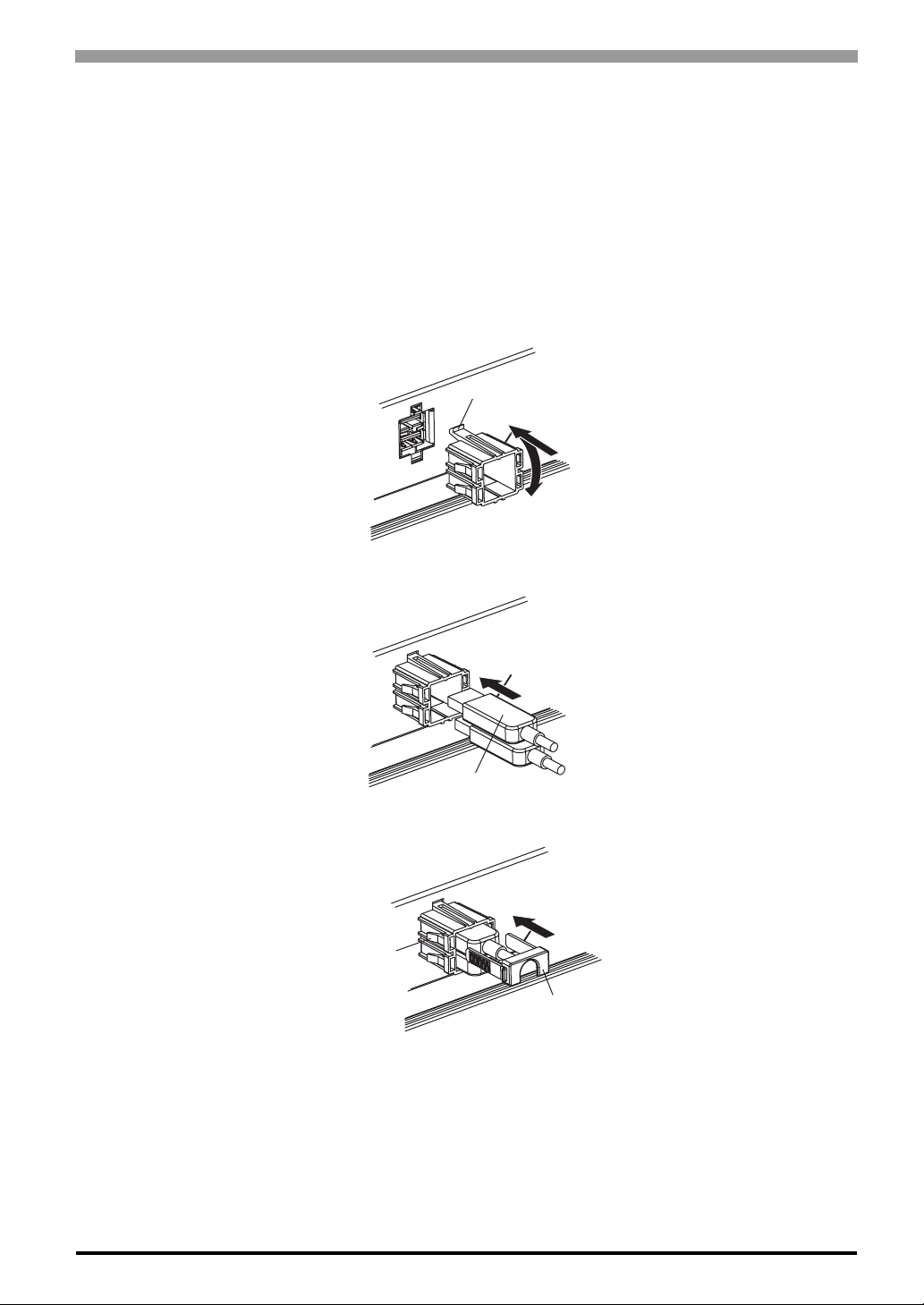
When using a USB device, attaching the USB holder to the USB Interface located on the side of the PS-A unit
prevents the USB cable Interface from becoming disconnected.
Attachment
(1) Attach the USB holder to the USB Interface on the side of the PS-A unit.
Hook the upper pick of the USB holder to the attachment hole of the PS-A unit and then insert the lower
pick as shown below to fix the USB holder.
Chapter 3 Hardware Installation
Pick
(2) Insert the USB cable into the USB Interface.
USB Cable
(3) Insert the USB cover into the tab of the USB holder to fix the USB cable.
Tab
USB Caver
In case of installing the second USB cable, repeat the steps (2) and (3).
3-19
Page 53
PS-3650A / PS-3651A User Manual
Removal
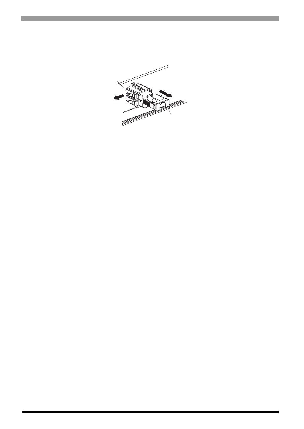
Remove USB Holder by the reverse procedures to the attachment procedures.
(1) Lift up the tab of the USB holder and then remove the USB cover.
(2) Remove the USB cable.
(3) Remove the picks pushing the USB holder from both top and bottom and then remove the USB holder
from PS-A unit.
Tab
(2)
(1)
USB Caver
3-20
Page 54

4 System Setup
1. Setup Procedures
2. System Parameters
This chapter explains how to enter the PS-A system settings, as well as the cautions required both before and
during set up.
4-1
Page 55
PS-3650A / PS-3651A User Manual
4.1 Setup Procedures
The BIOS setting up procedures are the following.
• Normally, use only the factory (default) settings.
(1) Connect a USB keyboard to the PS-A.
(2) Turn the PS-A’s power ON.
(3) After the boot-up screen comes up, press the [F2] key until the following screen appears.
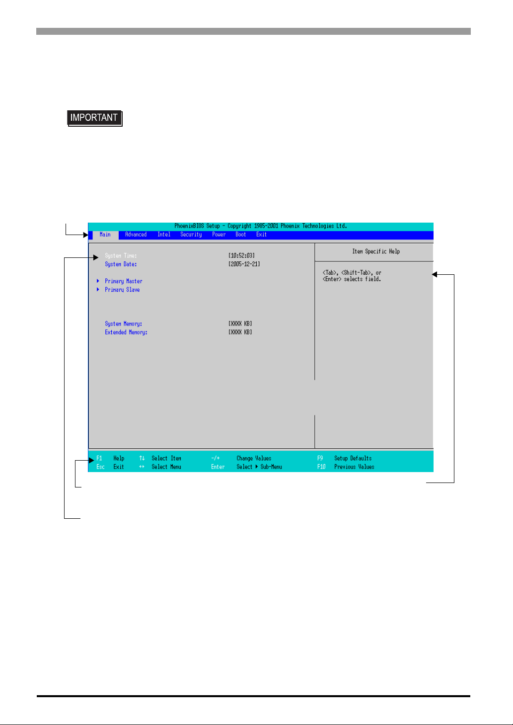
Menu
4-2
KEYBOARD ACTION KEYS
Provides a summary of the keyboard keys used to carry out the set-up.
SYSTEM SETTING SELECTION AREA
Each of the titles (areas) listed here contains system setting items.
(4) To use the [
displayed.
(5) To use the [
firm it by the [Enter] key. Now you can set up the item you selected.
I ] [ J ] arrow keys, change the menu contents. A setting screen of each system will be
K ] [ L ] arrow keys, move up and down the cursor to select an item of the system, then con-
Help area
Shows the information of
the items you selected.
Page 56
4.2 System Parameters
Select the items to set up the system information. Here, we introduce the system parameters of each item .
• Normally, use only the factory (default) settings.
4.2.1 Main
Chapter 4 System Setup
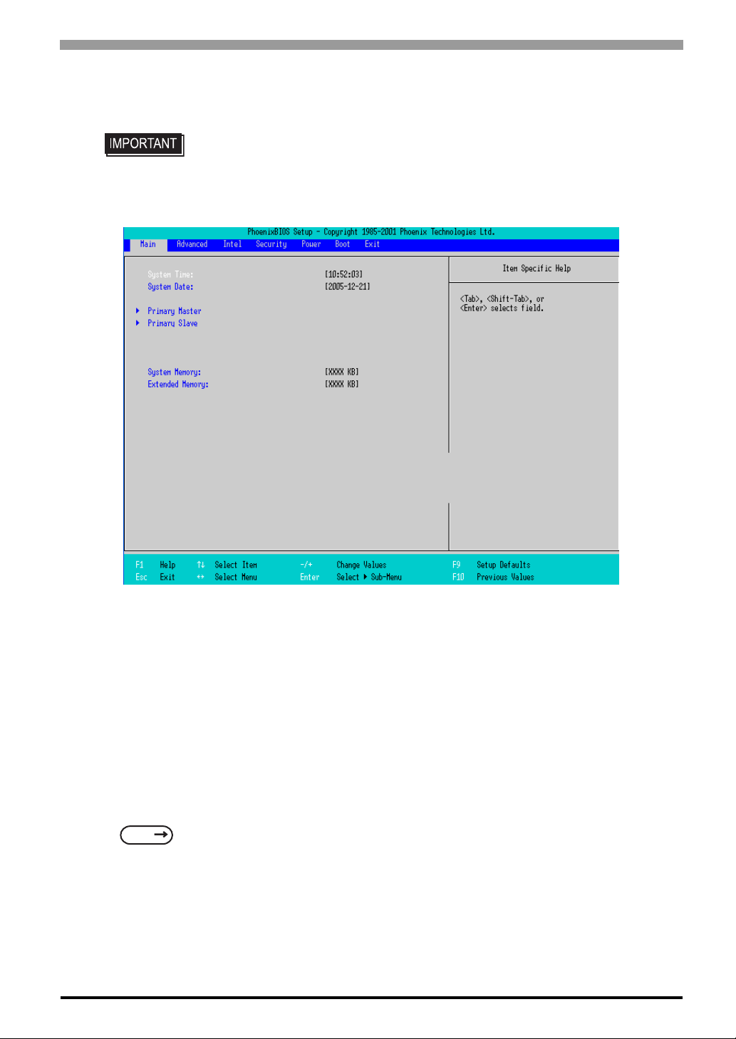
System Time
Shows the time which the PS-A currently recognizes. Move the cursor by the [Tab] key and set a proper time
for the PS-A by the [Tab], [+] and [-] keys because the factory default setting is the Japan’s Standard Time
(GMT+09:00).
System Date
Shows the date which the PS-A currently recognizes. Set a proper date for the PS-A by the [+] and [-] keys.
Primary Master / Primary Slave
Displays the name of devices connected to the PS-A. Pressing the [Enter] key will call up the Parameter
settings menu.
SEE
System Memory
Shows the capacity of the “System Memory”.
Extended Memory
Shows the capacity of the “Extended Memory”. It is the loaded memory - the size of the Video Memory 2048K byte.
Primary Master / Primary Slave (page4-4)
4-3
Page 57
PS-3650A / PS-3651A User Manual
Primary Master / Primary Slave
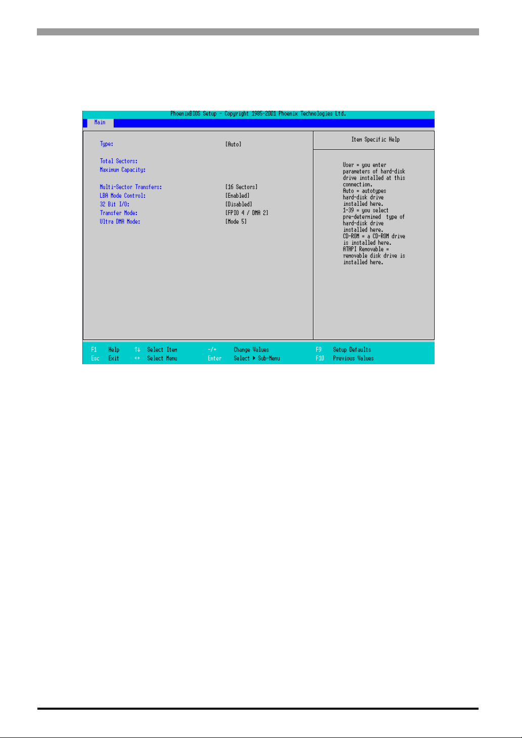
Point out the cursor at the [Primary Master] or [Primary Slave] on the “Main screen”, and then press the
[Enter] key, so that the following screen is shown.
Type
Specifies a type of drive which you use. Select from [Auto], [None], [ATAPI Removable], [CD-ROM], [IDERemovable], [Other ATAPI], or [User]. The factory default type is [Auto].
Total Sectors
Shows the number of disk sectors connected to the unit.
Maximum Capacity
Shows the maximum capacity of the disk connected to the unit.
Multi Sector Transfers
Specifies the number of sectors per block, which are transferred to the memory.When the [Type] is [None],
nothing is displayed. In other cases, select from [Disabled], [2 Sectors], [4 Sectors], [8 Sectors], or [16
Sectors].
LBA Mode Control
Enables or disables the Logical Block Address (LBA) instead of the Cylinders, Headers, and Sectors. When
the [Type] is [None], nothing is displayed. In other ca ses, select from [Disabled] or [Enabled].
32 Bit I/O
Enables or disables the 32 bit transferring between CPU and IDE controller. The choice is [Enabled] or
[Disabled]. When the [Type] is [None], nothing is displayed.
4-4
Page 58
Transfer Mode
Specifies a method of transferring data. When the [type] is [None], nothing is displayed. In other cases, select
from [Standard], [Fast PIO 1], [Fast PIO 2], [Fast PIO 3], [Fast PIO 4], [FPIO 3/DMA 1], or [FPIO 4/DMA 2]
Ultra DMA Mode
Specifies a Ultra DMA mode for the Hard drive. When the [type] is [None], nothing is displayed. In other
cases, select from [Disabled], [Mode 0], [Mode 1], [Mode 2], [Mode 3], [Mode 4], or [Mode 5].
4.2.2 Advanced
Chapter 4 System Setup
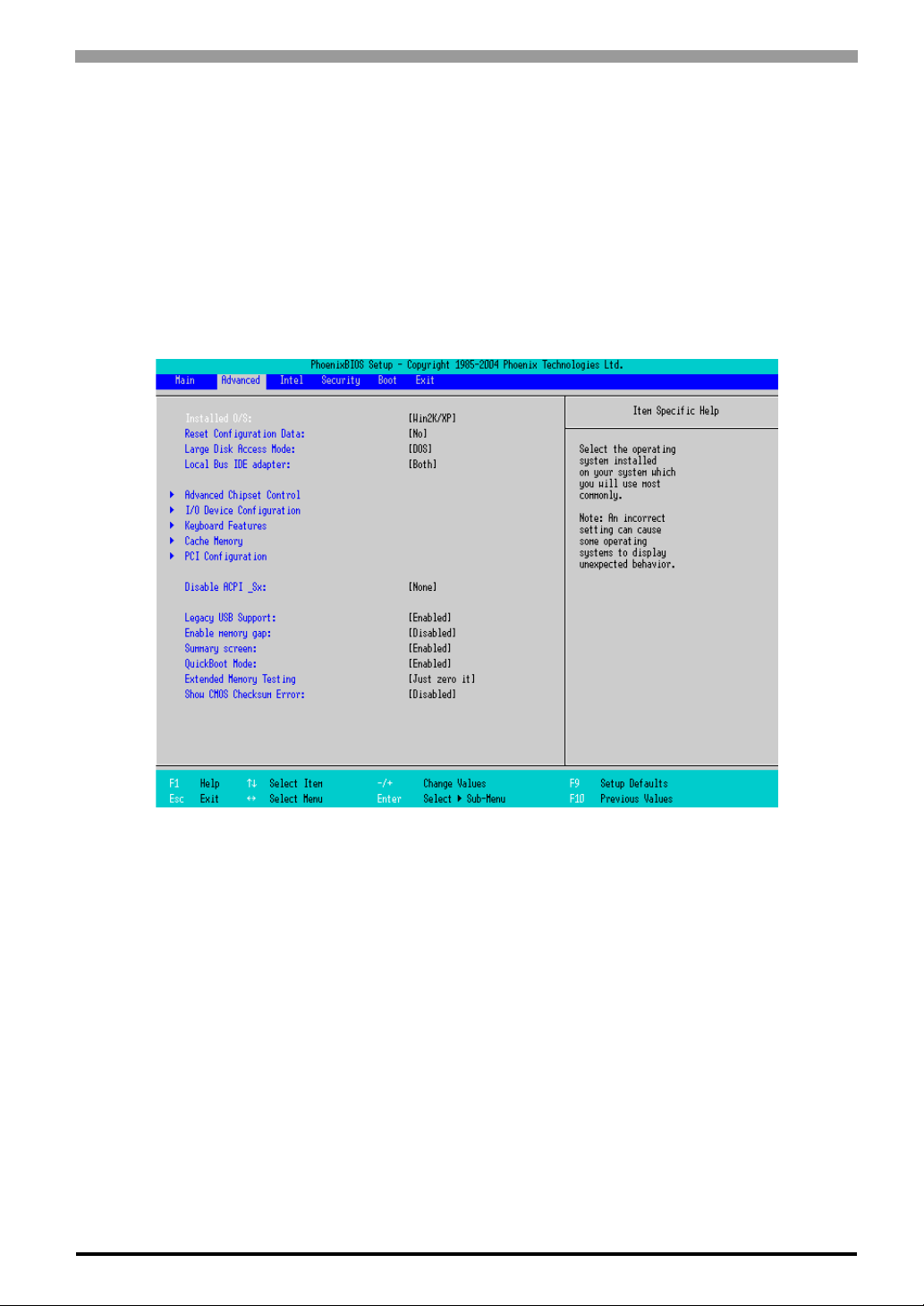
Installed O/S
Specifies a type of OS of the unit. Select from [Other], [Win95], [Win98], [WinMe], or [Win2K/XP]. The
factory default setting is [Win2K/XP].
Reset Configuration Data
Specifies whether you want to reset the Plug & Play information which is recorded in the Extended Syst em
Configuration Data (ESCD) Block of the CMOS RAM, when the system boots up next time. The choice is
[Yes] or [No] and the factory default setting is [No].
Large Disk Access Mode
When you use UNIX or NetWare for OS, the setting should be [Other]. The choice is [DOS] or [Other] and
the factory default setting is [DOS].
Local Bus IDE adapter
Specifies an enabled/disabled state for the IDE controller. Select from [Both], [Primary], [Secondary], or
[Disabled]. The the factory default setting is [Primary].
4-5
Page 59
PS-3650A / PS-3651A User Manual
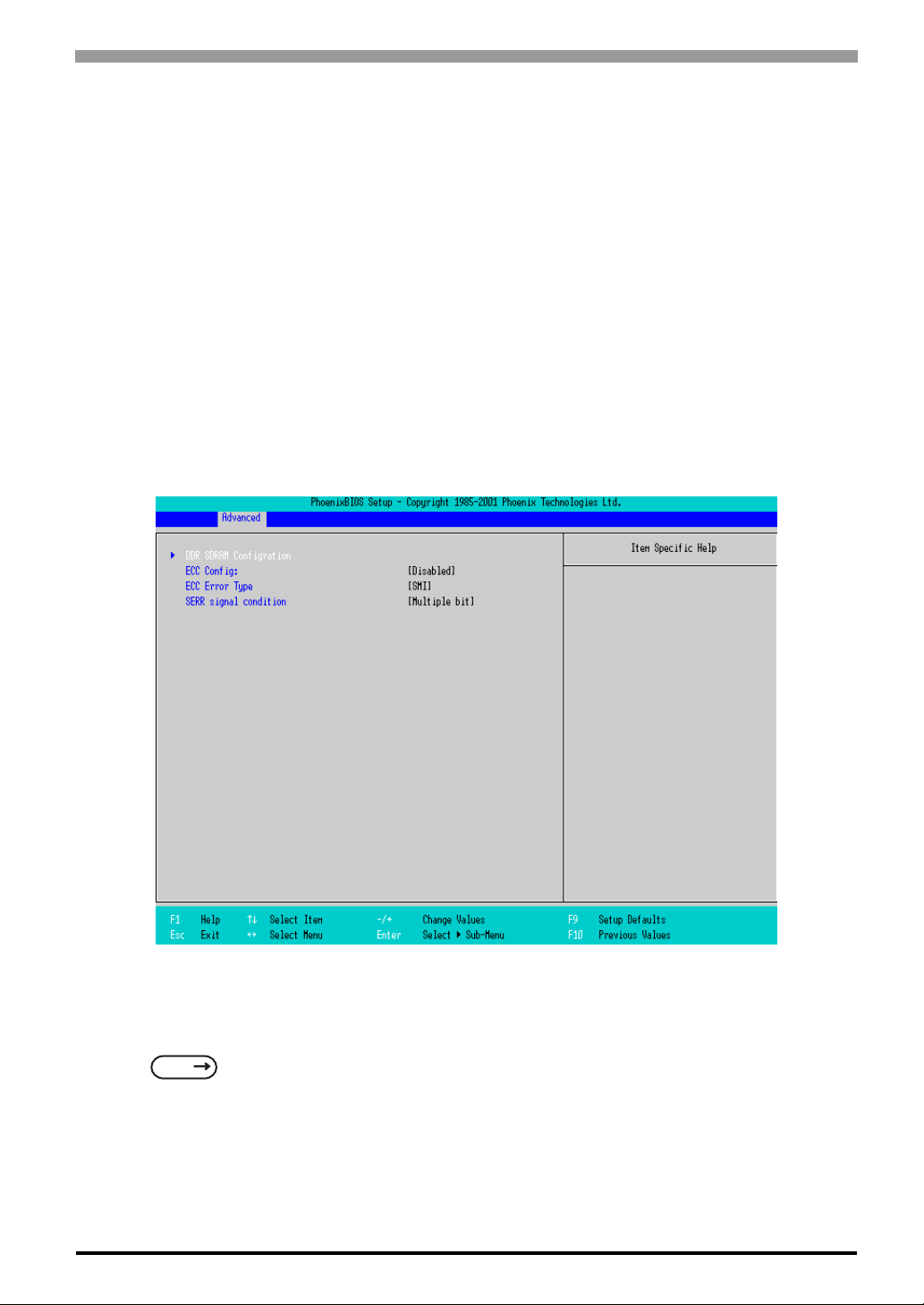
Advanced Chipset Control
Point the cursor to the [Advanced Chipset Control] and press the [Enter] Key, so that you can set up details.
SEE
I/O Device Configuration
Point the cursor to the [I/O Device Configuration] and press the [Enter] Key, so that you can go to the Serial
Port Setting screen
SEE
Keyboard Features
Point the cursor to the [Keyboard Features] and press the [Enter] Key, so that you can go to the keyboard setup screen.
SEE
Cache Memory
Point the cursor to the [Cache Memory] and press the [Enter] Key, so that you can go to the set-up screen for
Cache Memory.
Advanced Chipset Control (page4-7)
I/O Device Configuration (page4-9)
Keyboard Features (page4-10)
SEE
PCI Configuration
Point the cursor to the [PCI Configuration] and press the [Enter] Key, so that you can go to the set-up screen
for PCI IRQ.
SEE
Disable ACPI_Sx
Specifies the API’ s state. S elect from [ None] or [S1]. With this action, the selecting state will be enabled. The
factory default setting is [None].
Legacy USB Support
When the USB keyboard is used under DOS, specifies an enabled/disabled state for the USB. The choice is
[Enabled] or [Disabled]. The factory default setting is [Enabled].
Enable Memory gap
Specifies an enabled/disabled state for the Memory gap. The choice is [Enabled] or [Disabled]. The factory
default setting is [Disabled].
Summary screen
Specifies whether you need to display the Summary screen in running the daisy-chained devices. The choice
is [Enabled] or [Disabled]. The factory default setting is [Disable].
Cache Memory (page4-11)
PCI Configuration (page4-12)
QuickBoot Mode
4-6
Specifies whether the system boot-up should be “QuickBoot mode”. When the choice is [Disabled], it will
execute a system test at the system starting-up. The factory default setting is [Enabled].
Page 60
Chapter 4 System Setup
Extended Memory Testing
Specifies whether a test for the Extended Memory needs to be executed at the system starting-up. The test
types are listed below. The factory default setting is [Just Zero it].
[Normal] Normal test
[Just Zero it] Simple test
[None] No test
Show CMOS Checksum Error
Specifies whether you need to display the errors in case CMOS Checksum Error occurs. The choice
is [Enabled] or [Disabled]. The factory default setting is [Disabled].
Advanced Chipset Control
Point the cursor to the [Advanced Chipset Control] on the [Advanced] screen and pr ess the [Enter] Key, so
that the following screen will be displayed.
DDR SDRAM Configuration
Point the cursor to the [DDR SDRAM Configuration] and press the [Enter] Key, so that you can go to the
Memory Setting screen.
SEE
ECC Config
Specifies whether the ECC function for memory, which is a function of recovering errors, needs to be used.
The choice is [ECC] or [Disable]. The factory default setting is [ECC].
DDR SDRAM Configuration (page4-8)
4-7
Page 61
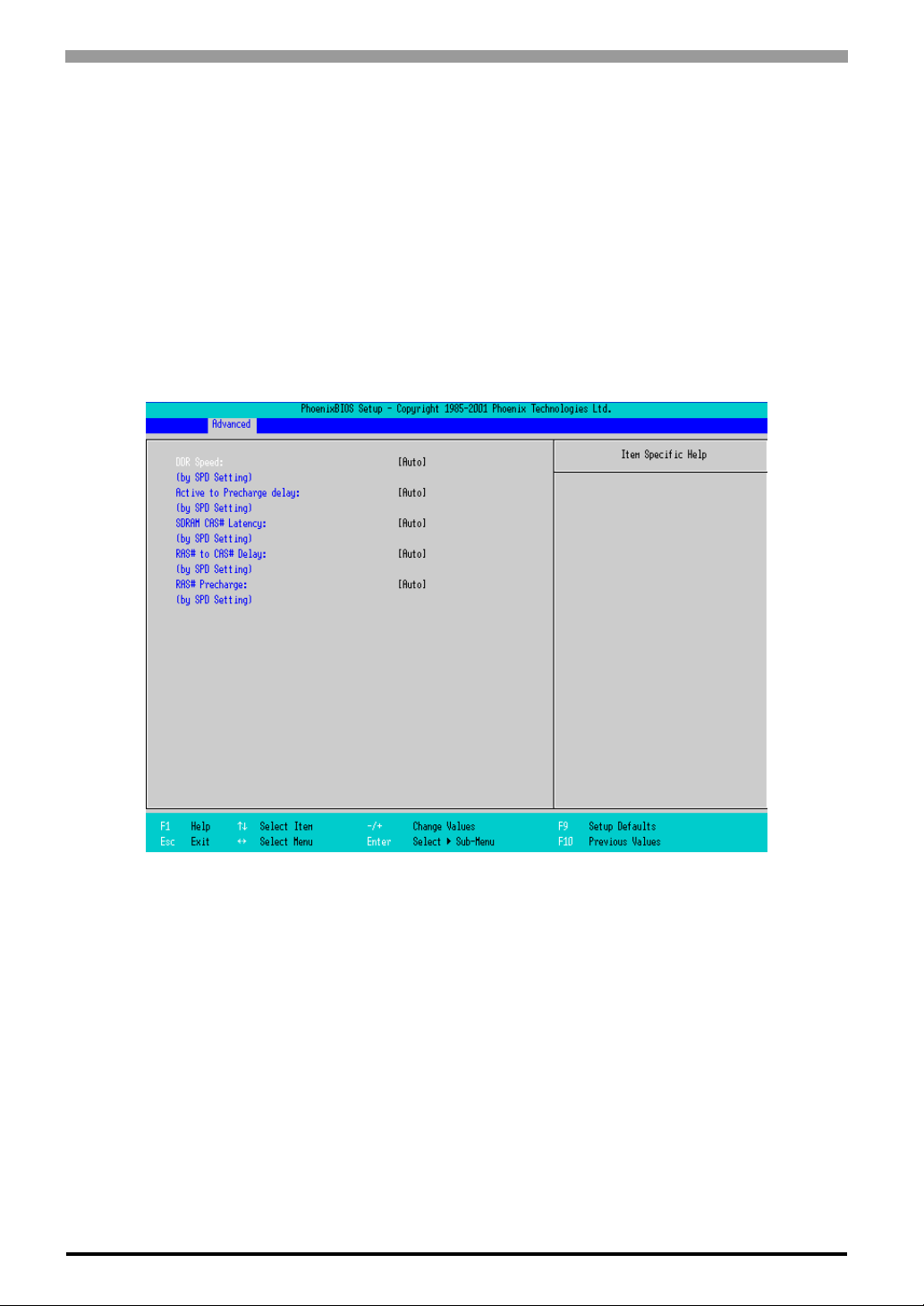
PS-3650A / PS-3651A User Manual
ECC Error Type
Specifies the interruption setting when an ECC error occurs. Select from [None], [NMI], [SMI], or [SCI]. The
factory default setting is [SMI].
SERR signal condition
Specifies error bit(s) for ECC. Select from [None], [Single bit], [Multiple bit], or [Both]. The factory default
setting is [Both].
DDR SDRAM Configuration
Point the cursor to the [DDR SDRAM Configuration] on the [Advanced Chipset Control] and press the
[Enter] Key, so that the following screen will be displayed.
DDR Speed
Specifies the clock frequency for the memory. Select from [Auto], [DDR2 00], [DDR266], or [DDR333 ]. The
factory default setting is [Auto].
Active to Precharge delay
Controls the timing of DRAM Precharge processing. Select from [Auto], [8Clocks], [7Clocks], [6Clocks], or
[5Clocks]. The factory default setting is [Auto].
SDRAM RAS# to CAS# Latency
Specifies the latency time for CAS. Select from [Auto], [2.5], or [2]. The factory default setting is [Auto].
RAS# to CAS Delay
Specifies a transfer timing from RAS to CAS. Select from [Auto], [4DDR SDRAM Clocks (DDR333
SDRAM)], [3DDR SDRAM Clocks], or [2DDR SDRAM Clocks]. The factory default setting is [Auto].
4-8
Page 62
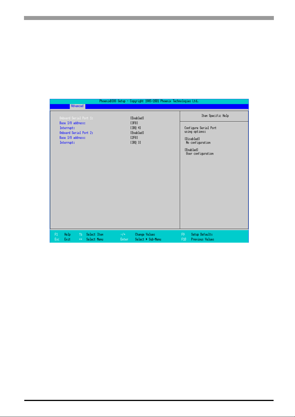
Chapter 4 System Setup
RAS# Precharge
Specifies the number of cycles of RAS precharge. Select from [Auto], [4DDR SDRAM Clocks (DDR333
SDRAM)], [3DDR SDRAM Clocks], or [2DDR SDRAM Clocks]. The factory default setting is [Auto].
I/O Device Configuration
Point the cursor to the [I/O Device Configuration] on the [Advanced] screen and press the [Enter] Key, so that
the following screen will be displayed.
On board Serial Port 1
Specifies an enabled/disabled state for the COM1. Select from [Disabled] or [Enabled]. The factory default
setting is [Enabled]. In addition, the factory default setting for Base I/O Address is [3F8], and for Interrupt is
[IRQ 4].
On board Serial Port 2
Specifies an enabled/disabled state for the COM2. Select from [Disabled] or [Enabled]. The factory default
setting is [Enabled]. In addition, the factory default setting for Base I/O Address is [2F8], and for Interrupt is
[IRQ 3]. The COM2 is used in the system.
4-9
Page 63
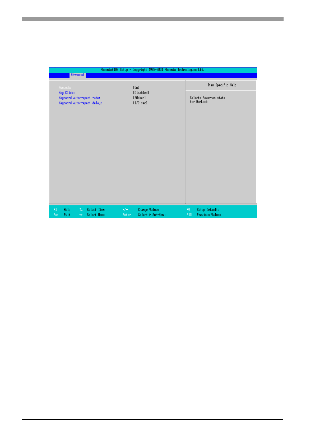
PS-3650A / PS-3651A User Manual
Keyboard Features
Point the cursor to the [Keyboard Features] on the [Advanced Chipset Control] and press the [Enter] Key, so
that the following screen will be displayed.
NumLock
Specifies the NumLock status. Select from [Auto], [On], or [Off]. The factory default setting is [On].
KeyClick
Specifies an enabled/disabled state for the keyboard’s click sound. Sele ct [Enabled] or [Disabled]. The factory
default setting is [Disabled].
Keyboard auto-repeat rate
Specifies the figures of how many times a key can input letters while being pressed for a second. Select from
[30/sec.], [26.7/sec.], [21.8/sec.], [18.5/sec.], [13.3/sec.], [10/sec.], [6/sec.], or [2/sec.]. The factory default
setting is [30/sec.].
Keyboard auto-repeat delay
Specifies a time duration until the auto- repeat f unction becomes enabled from a key is pressed. Select from [1/
4 sec.], [1/2 sec.], [3/4 sec.], or [1 sec.]. The factory default setting is [1/2 sec.].
4-10
Page 64
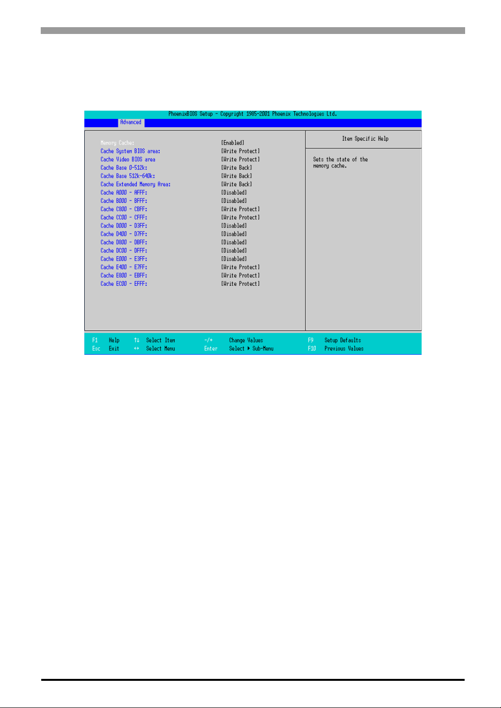
Chapter 4 System Setup
Cache Memory
Point the cursor to the [Cache Memory] on the [Advanced] screen and press the [Enter] Key, so that the
following screen will be displayed.
Memory Cache
Specifies an enabled/disabled state for t he Memory Cac he. The choice is [Enabled] or [Di sabled]. The factory
default setting is [Enabled].
Cache System Bios area
Specifies the cache set-up for the System BIOS a rea. The ch oice is [unc ached] or [Write Protect]. The factory
default setting is [Write Protect].
Cache Video BIOS area
Specifies the cache set-up for the VIDEO BIOS area. The choice is [uncached] or [Write Protect]. The factory
default setting is [Write Protect].
Cache Base 0-512k
Specifies the cache set-up for the Base Memory, 0 ~ 512k. Select from [uncached], [Write Through], [Write
Protect], or [Write Back]. The factory default setting is [Write Back].
Cache Base 512-640k
Specifies the cache set-up for the Base Memory, 512 ~ 62 0k. Select from [uncached], [Write Through], [Write
Protect], or [Write Back]. The factory default setting is [Write Back].
Cache Extended Memory Area
Specifies the cache set-up for the Extended Memory area. Select from [uncached], [Write Through], [Write
Protect], or [Write Back]. The factory default setting is [Write Back].
4-11
Page 65
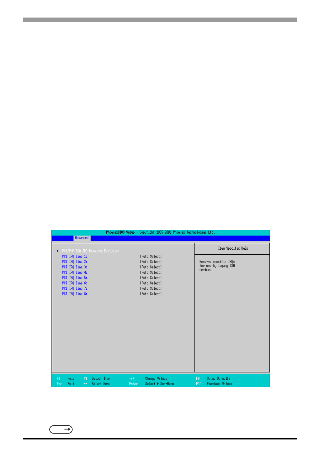
PS-3650A / PS-3651A User Manual
Cache xxxx-xxxx
Specifies the cache setting for each address. Select from [Disabled], [USWC Caching] (The address A000 AFFF and B000 - BFFF are only available.), [Write Through], [Write Protect], or [Write Back]. The factory
default setting is as follows.
A000 - AFFF Disabled
B000 - BFFF Disabled
C800 - CBFF Write Protect (VIDEO Memory)
CC00 - CFFF Write Protect
D000 - D3FF Disabled
D400 - D7FF Disabled
D800 - DBFF Disabled
DC00 - DFFF Disabled
E000 - E3FF Disabled
E400 - E7FF Write Protect (PXE)
E800 - EBFF Write Protect
EC00 - EFFF Write Protect
PCI Configuration
Point the cursor to the [PCI Configuration] on the [Advanced] screen and press the [Enter] Key, so that the
following screen will be displayed.
PCI/PNP ISA IRQ Resource Exclusion
Move the cursor to the [PCI/PNP ISA IRQ Resource Exclusion] on the [PCI Configuration] screen and press
the [Enter] Key, so that you can go to the ISA IRQ set-up screen.
SEE
PCI/PNP ISA IRQ Resource Exclusio n (pa ge4-13)
4-12
Page 66
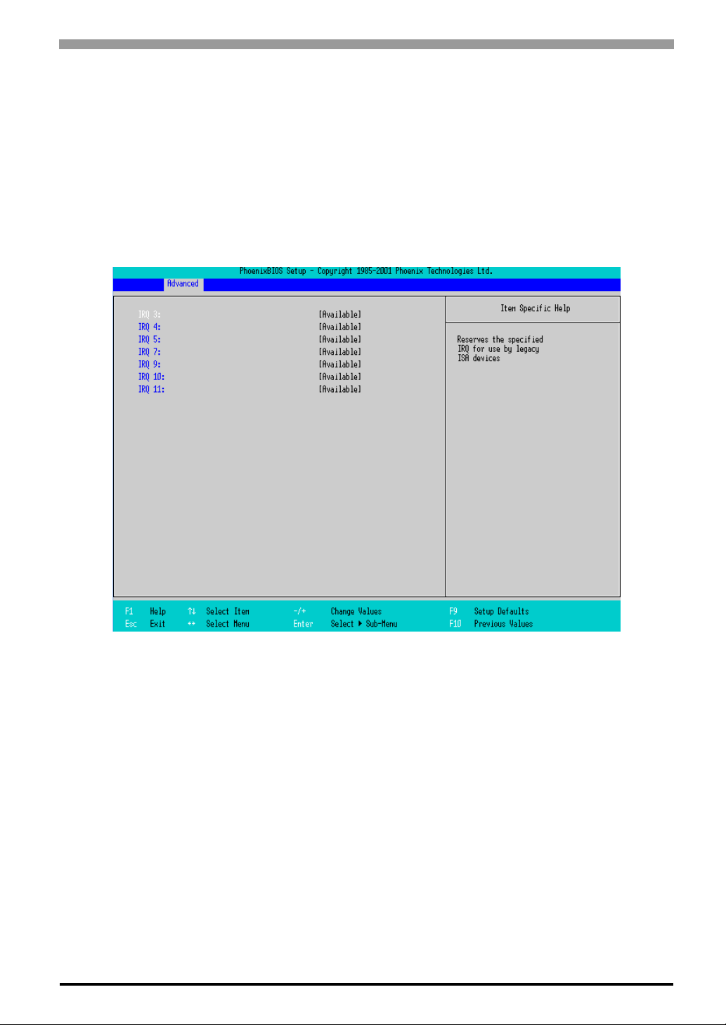
Chapter 4 System Setup
PCI IRQ line 1 ~ 8
Specifies the Interrupt Request Lines (IRQ) for PCI. Select from [Disabled], [Auto Select], [3], [4], [5], [7],
[9], [10], [11], [12], [14], or [15]. The factory default setting is [Auto Se lect].
PCI/PNP ISA IRQ Resource Exclusion
Point the cursor to the [PCI/PNP ISA IRQ Resource Exclusion] on the [PCI Configuration] screen and press
the [Enter] Key, so that the following screen will be displayed.
IRQ 3, 4, 5, 7, 9, 10, 11
Specifies the IRQ which is allocated to the legacy device. Select from [Available] or [Reserved]. The factory
default setting is [Available].
4-13
Page 67
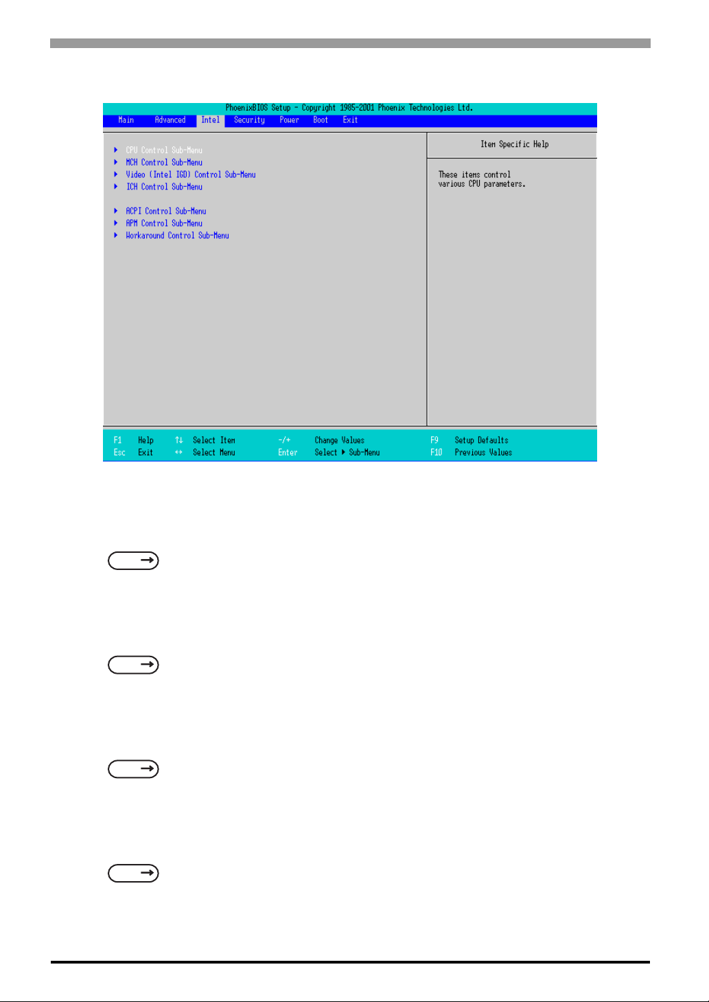
PS-3650A / PS-3651A User Manual
4.2.3 Intell
CPU Control Sub-Menu
Point the cursor to the [CPU Control Sub-Menu] on the [Intel] screen and press the [Enter] Key, so that you
can go to the [CPU] set-up screen.
SEE
MCH Control Sub-Menu
Point the cursor to the [MCH Control Sub-Menu] on the [Intel] screen and press the [Enter] Key, so that you
can go to the [MCH] set-up screen.
SEE
Video (Intel IGD) Control Sub-Menu
Point the cursor to the [Video (Intel IGD) Control Sub-Menu] on the [Intel] screen and press the [Enter] Key,
so that you can go to the set-up screen for display.
SEE
ICH Sub-Menu
Point the cursor to the [ICH Control Sub-Menu] on the [Intel] screen and press the [Enter] Key, so that you
can go to the [ICH] set-up screen.
SEE
CPU Control Sub-Menu (page4-15)
MCH Control Sub-Menu (page4-16)
Vi deo (Intel IGD) Control Sub-Menu (page4-18)
ICH Control Sub-Menu (page4-19)
4-14
Page 68
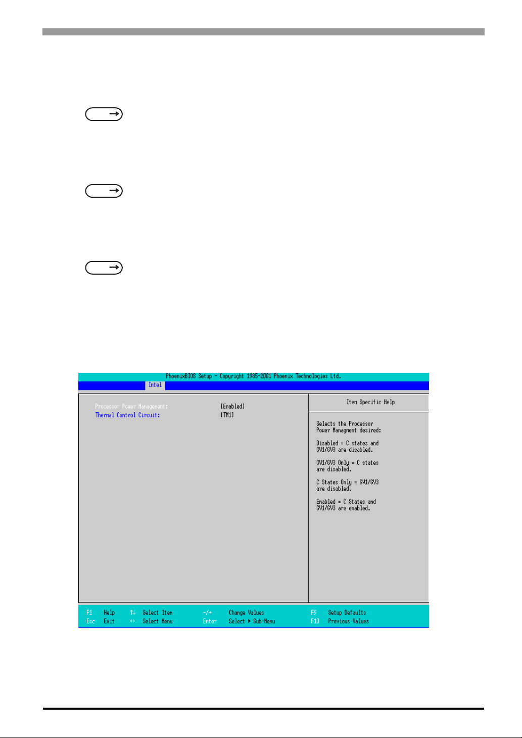
Chapter 4 System Setup
ACPI Control Sub-Menu
Point the cursor to the [ACPI Control Sub-Menu] on the [Intel] screen and press the [Enter] Key, so that you
can go to the [ACPI] set-up screen.
SEE
APM Control Sub-Menu
Point the cursor to the [APM Control Sub-Menu] on the [Intel] screen and press the [Enter] Key, so that you
can go to the [APM] set-up screen. If you use APM OS, you are requested to set up this configuration.
SEE
Workaround Control Sub-Menu
Point the cursor to the [W orkaround Control Sub-Menu] on the [Intel] screen and press the [Enter] Key, so
that you can go to the set-up screen of the whole platform.
SEE
ACPI Control Sub-Menu (page4-21)
APM Control Sub-Menu (page4-22)
Workaround Control Sub-Menu (page4-23)
CPU Control Sub-Menu
Point the cursor to the [CPU Control Sub-Menu] on the [Intel] screen and press the [Enter] Key, so that the
following screen will be displayed.
Processor Power Management
This is a function that controls the processor’s power state. Select from [Disabled] or [C States Only]. The
factory default setting is [C States Only] and the default should be applied.
4-15
Page 69
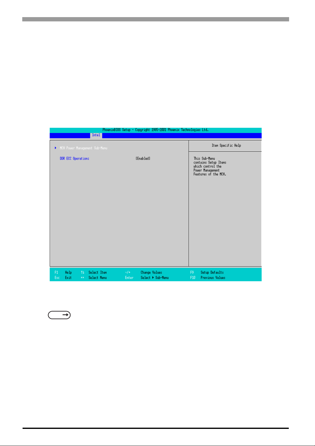
PS-3650A / PS-3651A User Manual
Thermal Control Circuit
This is a function that protects the CPU’s temperature, and its setting is a situation that if it exceeds the limit
that CPU is able to work properly. Select from [Disabled], [TM1], or [TM2]. The factory default setting is
[TM2].
MCH Control Sub-Menu
Point the cursor to the [MCH Control Sub-Menu] on the [Intel] screen and press the [Enter] Key, so that the
following screen will be displayed.
MCH Power Management Sub-Menu
Goes to the Chipset set-up screen.
SEE
DDR ECC Operation
Specifies whether you use ECC memory or not. The choice is [Enabled] or [Disabled] and the default factory
setting is [Disabled].
MCH Power Management Sub-Menu (page4-17)
4-16
Page 70
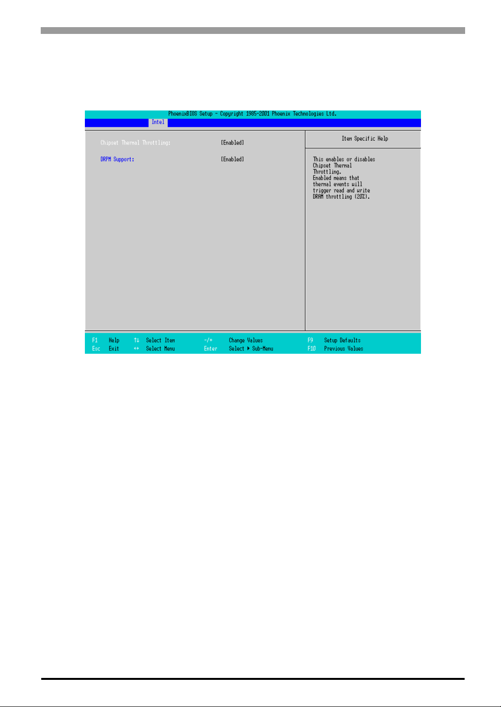
Chapter 4 System Setup
MCH Power Management Sub-Menu
Point the cursor to the [MCH Power Management Sub-Menu] on the [Intel] screen and press the [Enter] Key,
so that the following screen will be displayed.
Chipset Thermal Throttlin g
Specifies a thermal throttle, a system to prevent a themorunway, for chipset. The choice is [Enabled] or
[Disabled]. The factory default setting is [Enabled].
DRPM Support
Specifies an enabled/disabled state for the setting of Dynamic Row Power Management. The choice is
[Enabled] or [Disabled]. The factory default setting is [Enabled].
4-17
Page 71
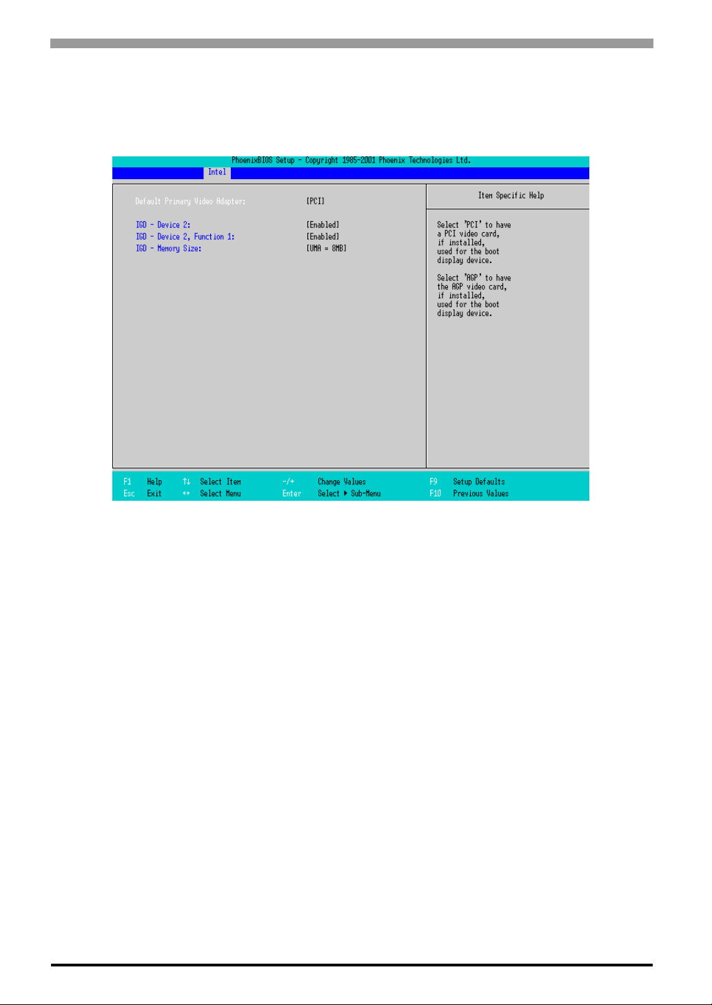
PS-3650A / PS-3651A User Manual
Video (Intel IGD) Control Sub-Menu
Point the cursor to the [Video (Intel IGD) Control Sub-Menu] on the [Intel] screen and press the [Enter] Key,
so that the following screen will be displayed.
Default Primary Video Adapter
Selects a priority of the [PCI] or [AGP] which should take for displaying. The factory default setting is [PCI].
IDG-Device 2
Specifies an enabled/disabled state for the Display Contoller. The factory default setting is [Enabled] and the
default should be applied.
IDG-Device 2, Function 1
Specifies an enabled/disabled state for the display contoller. The factory default setting is [Enabled] and the
default should be applied.
IGD-Memory Size
Specifies an allocation capacity for the Video Memory. Select from [UMA=1MB], [UMA=8MB],
[UMA=16MB], or [UMA=32MB]. the factory default setting is [UMA=8MB].
4-18
Page 72
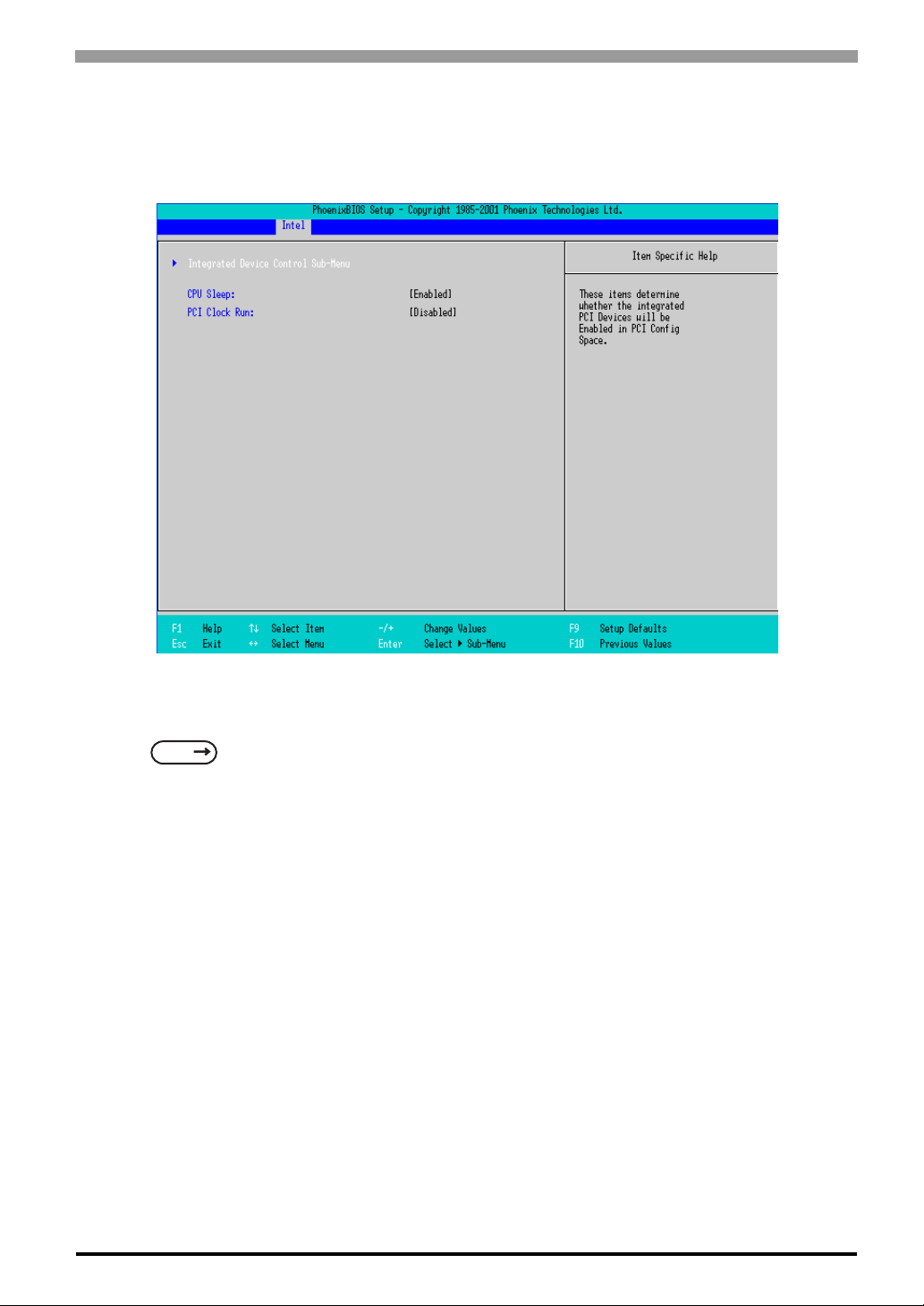
Chapter 4 System Setup
ICH Control Sub-Menu
Point the cursor to the [ICH Control Sub-Menu] on the [Intel] screen and press the [Enter] Key, so that the
following screen will be displayed.
Integrated Device Control Sub-Menu
Goes to the setting screen where an enabled/disabled state for the USB, LAN and PCMCIA is specified.
SEE
CPU Sleep
Specifies whether the CPU needs power saving . The choice is [Enabled] or [Disabled]. The factory default
setting is [Enabled].
Integrated Device Control Sub-Menu (page4-20)
4-19
Page 73
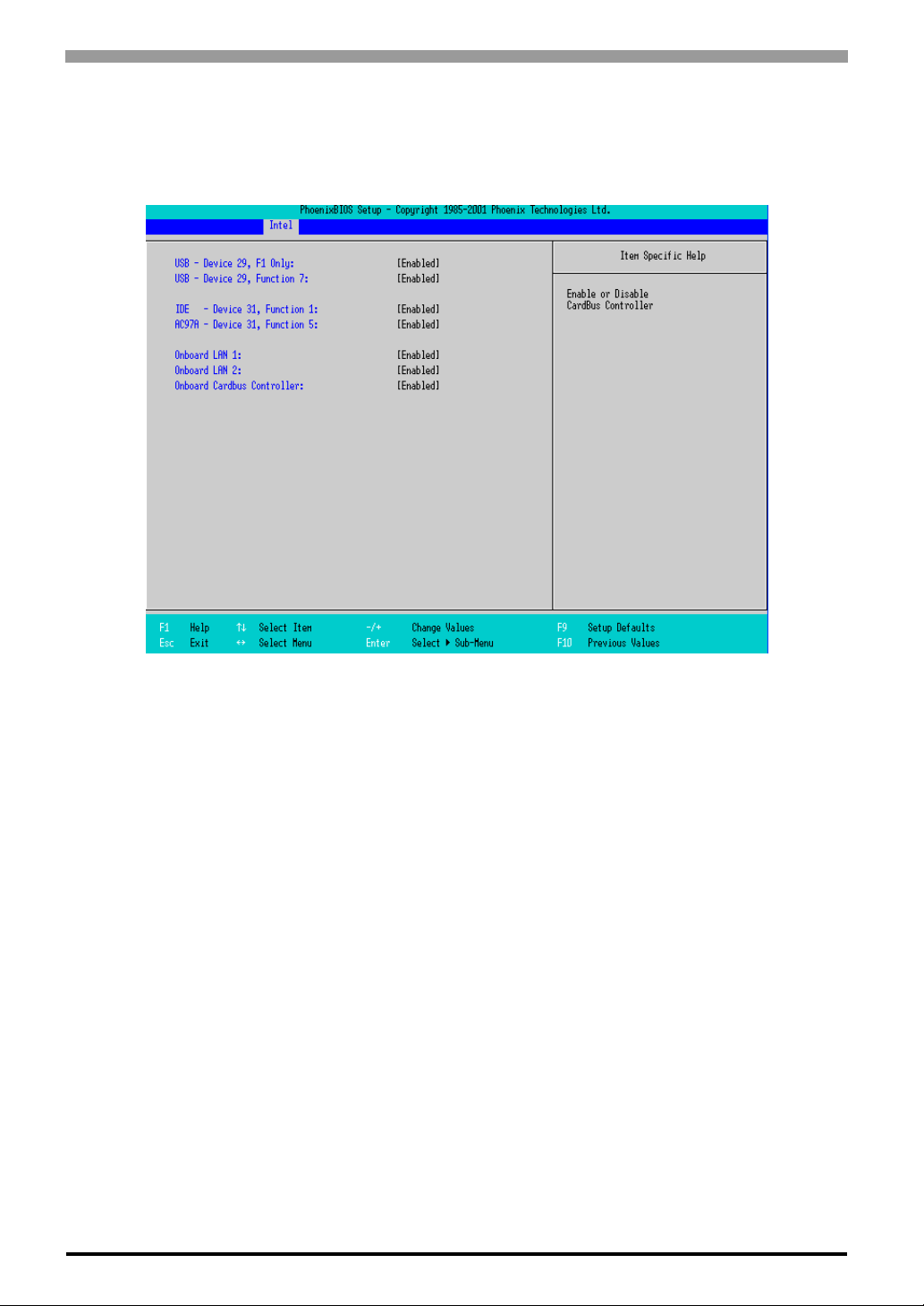
PS-3650A / PS-3651A User Manual
Integrated Device Control Sub-Menu
Point the cursor to the [Integrated Device Control Sub-Menu] from the [ICH Control Sub-Menu] on the [Intel]
screen and press the [Enter] Key, so that the following screen will be displayed.
USB-Device 29, F1 only / USB-Device 29, Function 7
Specifies an enabled/disabled state for the USB device. The choice is [Enabled] or [Disabled]. The factory
default setting is [Enabled].
IDE-Device 31, Function 1
Specifies an enabled/disabled state for the IDE device. The choice is [Enabled] or [Disabled]. The factory
default setting is [Enabled].
AC97A-Device 31, Function 5
Specifies an enabled/disabled state for the AC97 Audio. The choice is [E nabled] or [Disabled]. The factory
default setting is [Enabled].
Onboard LAN 1, 2
Specifies an enabled/disabled state for the Onboard LAN 1,2. The choice is [Enabled] or [Disabled]. The
factory default setting is [Enabled].
Onboard Cardbus Controller
Specifies an enabled/disabled state for the PCMCIA slot. The choice is [Enabled] or [Disabled]. The factory
default setting is [Enabled].
4-20
Page 74
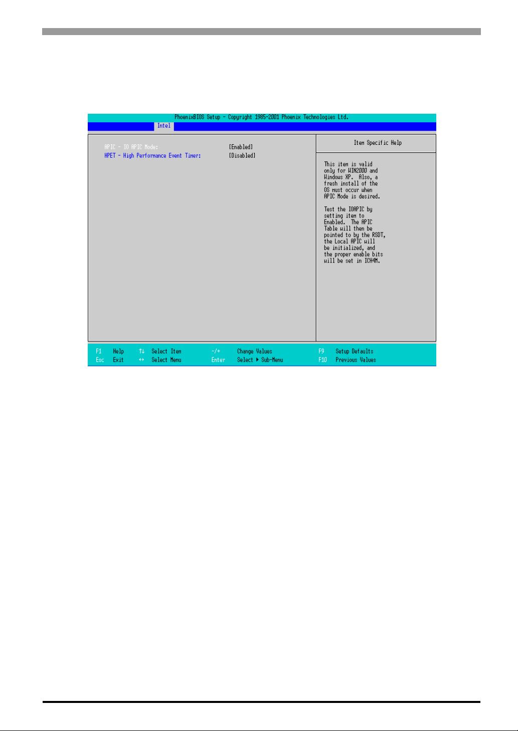
Chapter 4 System Setup
ACPI Control Sub-Menu
Point the cursor to the [ACPI Control Sub-Menu] on the [Intel] screen and press the [Enter] Key, so that the
following screen will be displayed.
ACPI-IO APIC Mode
Specifies an enabled/disabled state for the APIC. The choice is [Enabled] or [Disabled]. The factory default
setting is [Enabled].
HPET-High Performance Event Timer
Specifies the timer setting for the High Precision Event T imer. The choice is [Enabled] or [Disabled]. The
factory default setting is [Disabled].
4-21
Page 75
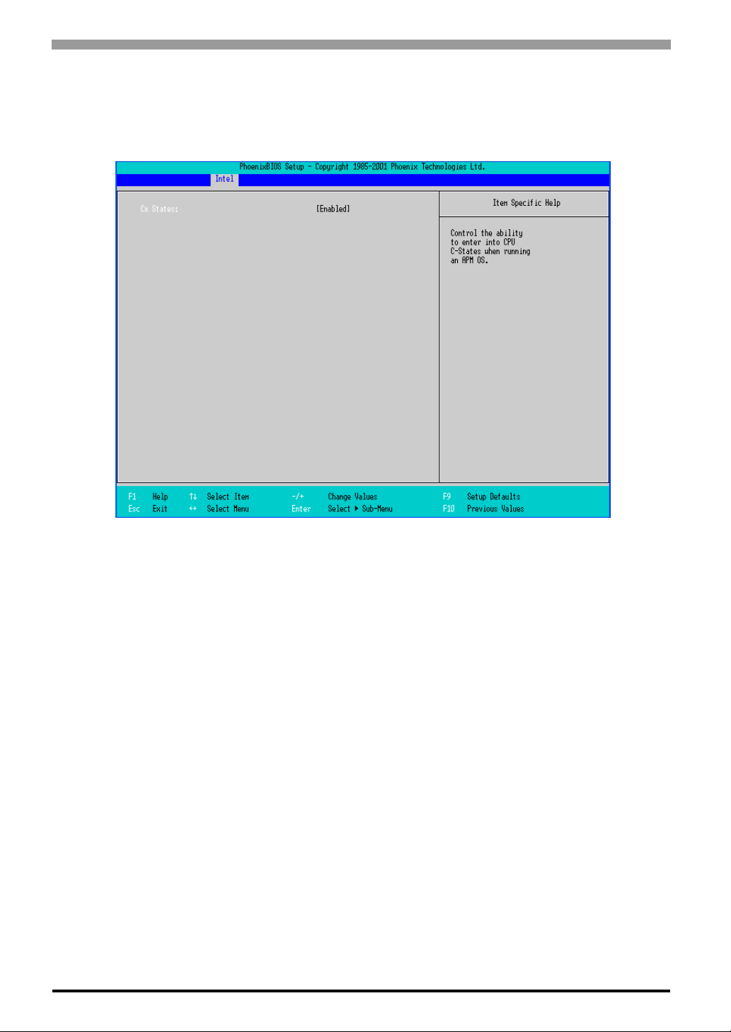
PS-3650A / PS-3651A User Manual
APM Control Sub-Menu
Point the cursor to the [APM Control Sub-Menu] on the [Intel] screen and press the [Enter] Key, so that the
following screen will be displayed.
CX Status
Specifies whether you use a power saving state when using APM OS. The choice is [Enabled] or [Disabled].
The factory default setting is [Enabled].
4-22
Page 76
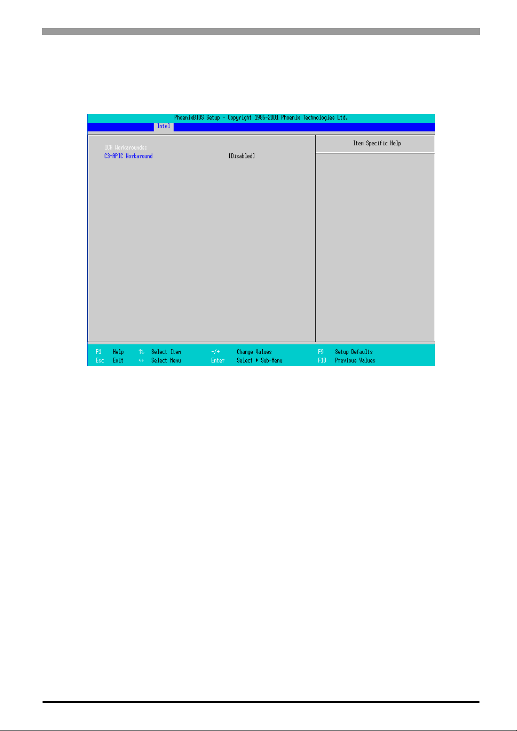
Chapter 4 System Setup
Workaround Control Sub-Menu
Point the cursor to the [W orkaround Control Sub-Menu] on the [Intel] screen and press the [Enter] Key, so
that the following screen will be displayed.
C3-APIC Workaround
Select from [Enabled], [Auto], or [Disabled]. The factory default setting is [Enabled].
4-23
Page 77
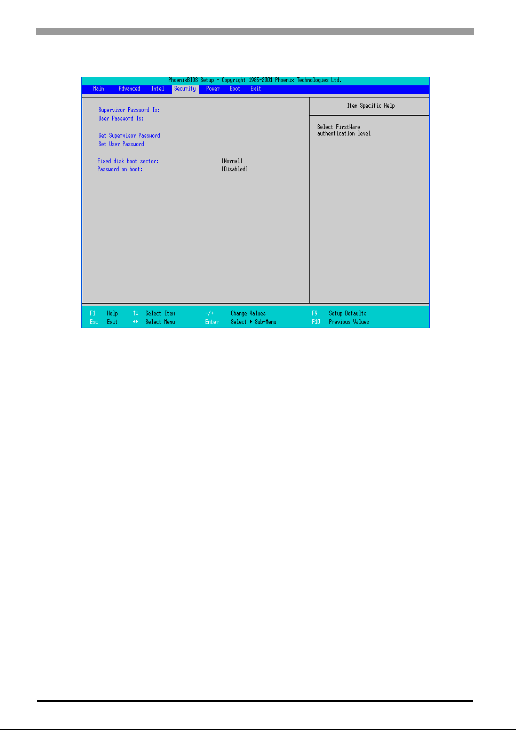
PS-3650A / PS-3651A User Manual
4.2.4 Security
Supervisor Password Is
Displayed as “Set“ when the password is set. Since no password has been set at factories, the factory default
setting is [Clear].
User Password Is
Displayed as “Set“ when the password is set. Since no password has been set at factory, the factory default
setting is [Clear]. Note that BIOS setting is not allowed with a User Password.
Set Supervisor Password / Set User Password
Specifies a password. When any password is not needed, do not input any values in the new password setting
and press just the [Enter] key.
Fixed disk boot sector
Specifies whether writing into the boot sector on the hard disk is not allowed. Select from [Normal], [Write
Protect], or [Protect]. The factory default setting is [Normal].
Password on boot
Specifies whether a password should be needed at the Start-Up. The choice is [Enabled] or [Disabled]. The
factory default setting the is [Disabled].
4-24
Page 78
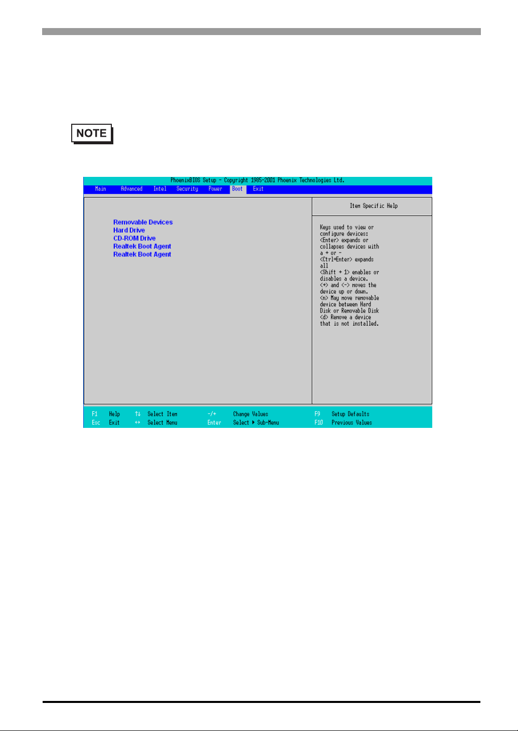
4.2.5 Boot
Specifies an order for boot-up devices. It searches from the top in sequence. By using the [+] or [-] keys,
change its order.
Chapter 4 System Setup
• Be sure to set and confirm the Boot menu each time when you install new hard disk or commercial USB memory.
Removable Device
Displays other removal media if like USB Floppy drives are connected.
Hard Drive
Displays the HDD and CF card units.
CD-ROM Drive
Displays the CD-ROM drives.
Realtek Boot Agent
Used for booting from the Onboard LAN.
4-25
Page 79
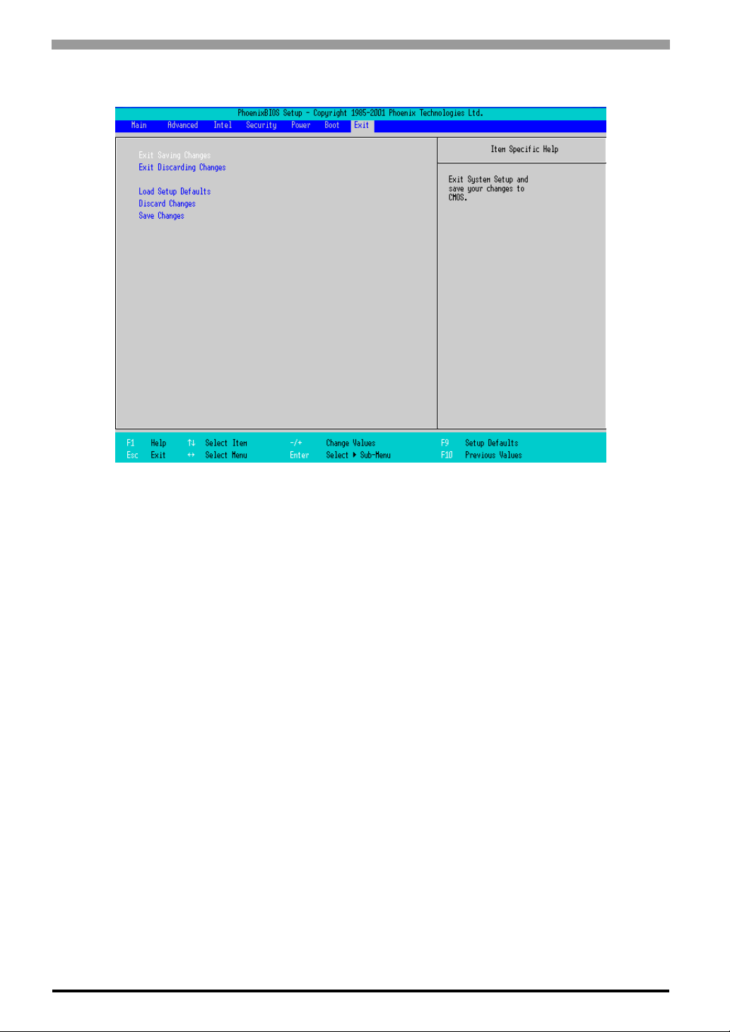
PS-3650A / PS-3651A User Manual
4.2.6 Exit
Exit Saving Changes
Point the cursor to the [Exit Saving Changes] on the [Exit] screen and press the [Enter] Key, the current
configuration is saved and the setting procedure is ended.
Exit Discarding Changes
Point the cursor to the [Exit Discarding Changes] on the [Exit] screen and press the [Enter] Key, the current
configuration is NOT saved but the setting procedure is ended.
Load Setup Defaults
Point the cursor to the [Load Setup Defaults] on the [Exit] screen and press the [Enter] Key, all of the current
configuration is back to the factory default settings.
Discard Changes
Point the cursor to the [Discard Changes] on the [Exit] screen and press the [Enter] Key, the current modified
configuration is canceled and the previous setting values are reloaded.
Save Changes
Point the cursor to the [Save Changes] on the [Exit] screen and press the [Enter] Key, the current
configuration which you modified is saved.
4-26
Page 80

5 Setting up
Software
1. CD-ROM Contents
2. Setting Up Your PS-A Unit
3. Installing Drivers
4. Special Application Program Features
5. Cautions When Using Windows®2000/Windows®XP
An accessory CD-ROM disk is included with the PS-A unit. This CD-ROM contains special programs
®
designed for the PS-A that are not supported by standard versions of Windows
2000 and Windows®XP.
5-1
Page 81
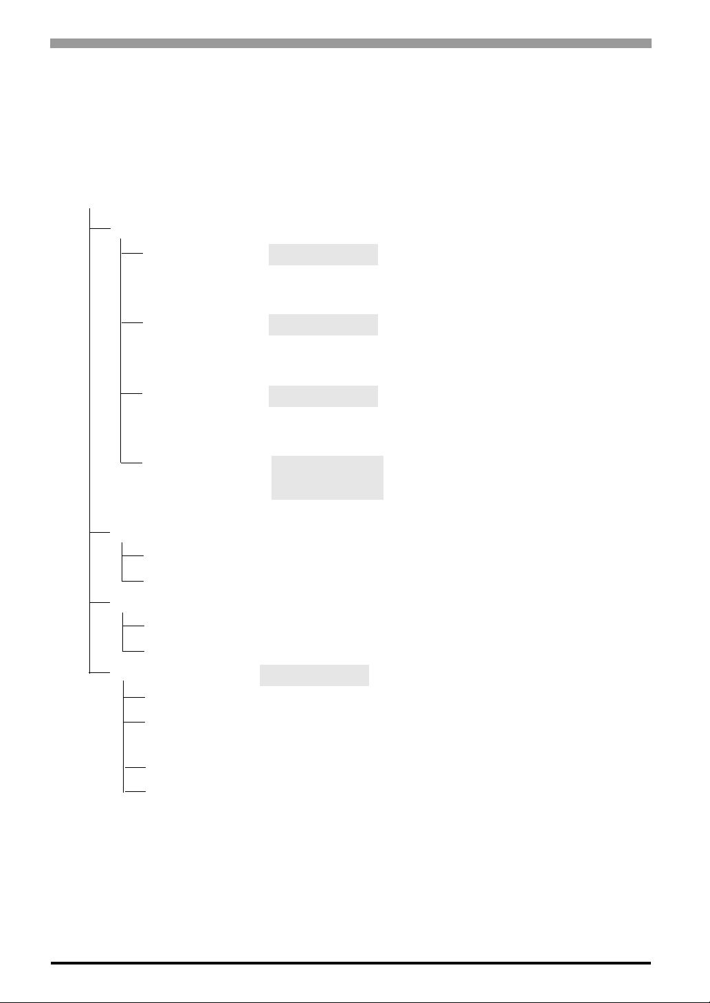
PS-3650A / PS-3651A User Manual
5.1 CD-ROM Contents
5.1.1 Software Configuration
This section explains the organization of the software included in the accessory CD-ROM by the folder composition diagram.
PS-3650A/PS-3651A User Manual & Driver CD
[Driver]
[Audio] Audio Driver <Supported OS types>
[Chipset] Chipset Driver <Supported OS types>
[Display] Display Driver <Supported OS types>
[UPDD] Mouse Emulation <Supported OS types>
Software Windows
[Manual] <User Manual>
[Eng] PDF Manual (English)
Windows
Windows
Windows
Windows
Windows
Windows
Windows
®
®
®
®
®
®
®
®
2000
XP
2000
XP
2000
XP
2000
XP
5-2
[Jpn] PDF Manual (Japanese)
[Reader] <PDF Reader>
®
[Eng] Acrobat
[Jpn] Acrobat
Reader (English)
®
Reader (Japanese)
[Utility] Utility Setup <PS-A Utility Tools>
[Shutdown] Remote Shutdown Installer
[RASSvr] Remote RAS for Server PC Installer
[Win2000] <Supported OS types>
®
[WinXP] Windows
Windows
2000
®
XP
Page 82
5.2 Setting Up Your PS-A Unit
There are two types of PS-A units. One has a hard disk with no pre-installed OS and the other has a hard disk
with a pre-installed OS. Therefore, the setup procedures used will differ.
5.2.1 Setting Up an HDD with no Pre-installed OS
First, when you use a hard disk with no pre-installed OS, you will need to install either W indows®2000 or
®
Windows
Installing the HDD Unit
Check to see if a hard disk unit is installed in your PS-A unit. If it is not, install the “PS365XA-HD40”
(the HDD unit with no pre-installed OS) prior to going to the next step. For the installation method, refer to
the Installation Guide that comes with the HDD unit with no pre-installed OS.
Setting Up HDD Unit System Information
Check to see if a hard disk unit is installed in your PS-A unit. If it is not, install the HDD unit with no pre-
XP. Y ou also need to install any required utility software.
Chapter 5 Setting up Software
installed OS. After that, you will need to set up a variety of system information. Set up this information so that
the system recognizes the newly-installed hard disk drive. For detailed setup procedures about the hard disk,
refer to the Installation Guide that comes with the HDD unit with no pre-installed OS.
Setting Up the OS
Install your operating system. For the setup procedures about the OS, refer to that product's installation manual.
• Specify [Disabled] for the USB-Device29 and the Function7 of the BIOS when you
®
install commercial Windows
SEE
• The PS-A unit supports Windows
Pack 2. The PS-A unit performance cannot be guaranteed when any other
operating system is used.
Integrated Device Control Sub-Menu (page4-20)
, using a USB CD-ROM drive.
®
2000 Service Pack 4 and Windows®XP Service
PS-A Utility Setup
Install the necessary drivers and utility software from the “PS-3650A/PS-3651A User Manual & Driver CD”
supplied with the PS-A unit.
• T o insta ll the software on the PS-A, the USB CD-ROM drive is required.
• A USB keyboard is required to install the OS, etc.
5-3
Page 83
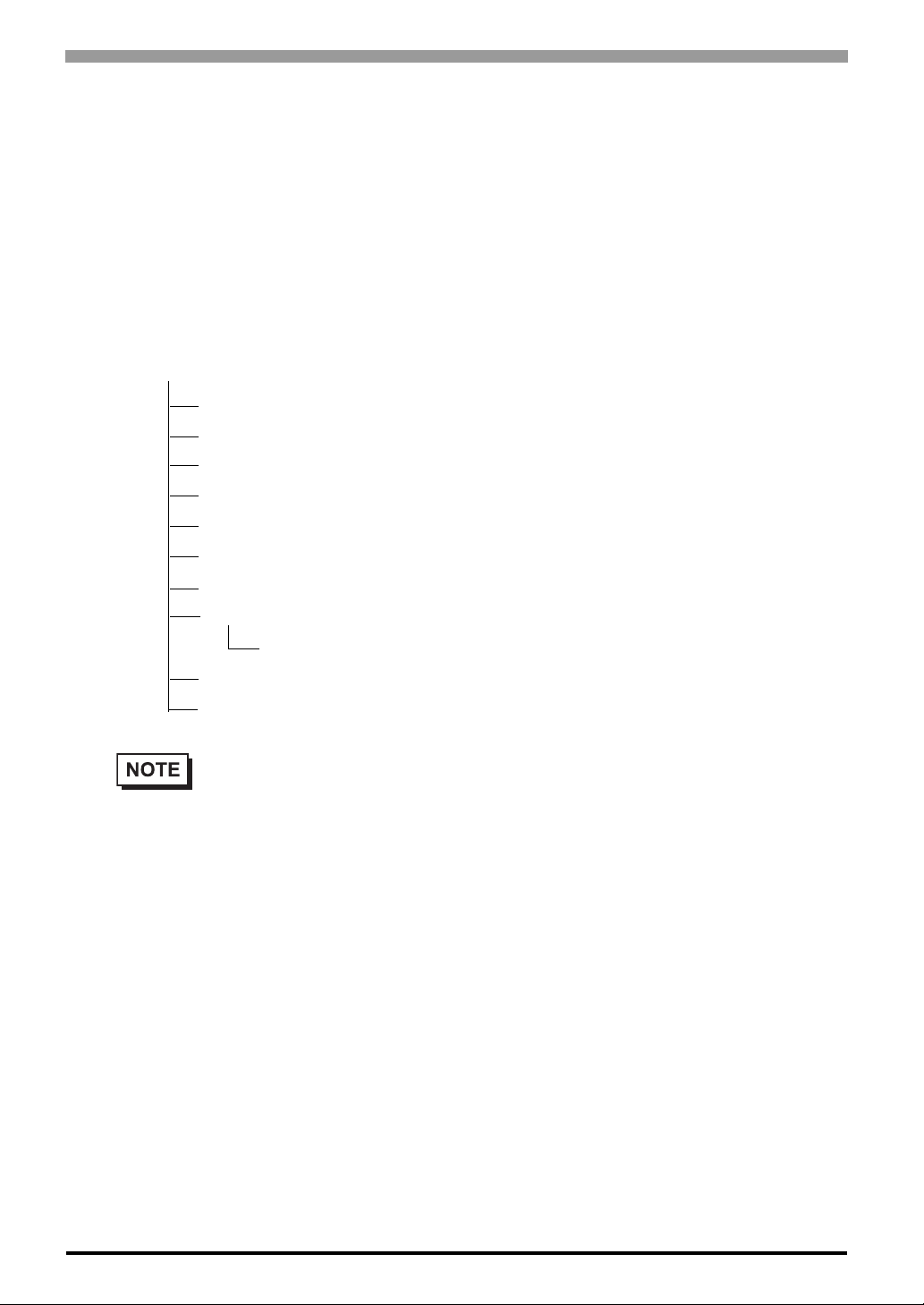
PS-3650A / PS-3651A User Manual
Installing Software from the provided CD-ROM
Install the software from the provided CD-ROM “PS-3650A/PS-3651A User Manual & Driver CD”.
To begin the installation, click on the “Setup.exe” file in the followi ng folder.
Example) With Windows
D:\Utility\WinXP\Setup.exe (When the CD-ROM drive is “D”)
PS-A Hard Disk Data
Setting up the PS-A unit’s utilities will create a [Proface] folder on the C drive. The following diagram
describes the configuration of this folder.
[Proface]
[Api] API-DLL
[Audio] Audio Driver
[Blsaver] Backlight Control Screen Saver
[Chipset] Chipset Driver
[Disp] Backlight Control Console Application
[Display] Graphic Accelerator Driver
®
XP
[Keyclick] Keyboard Emula tion Application
[Shutdown]
[Client] Remote Shutdown Client
[Sysmon] System Monitor/RAS Application
[UPDD] Mouse Emulation Software
• The actual organization may differ from the above depending on your PS-A unit’s OS.
• Setting up the PS-A unit’s utilities automatically copies the hardware control driver
(Sysmon.sys) to the system folder.
5-4
Page 84

5.2.2 Setting Up an HDD with Pre-installed OS
Use the following steps to set up your PS-A unit’s HDD unit, which contains the operating system of Win-
®
2000 or Windows®XP, related drivers and utility software.
dows
• Each pre-installed operating system on the hard disk in the PS-A unit is designed specially for
PS-3650A/PS-3651A.
Installing the HDD Unit
After opening the PS-A unit’s packing box, check that a hard disk unit is installed. If it is not, install an HDD
unit with the pre-installed OS. For the installation method, refer to the Installation Guide that comes with the
HDD unit with the pre-installed OS.
Setting Up the PS-A Unit’s System Information
If your PS-A unit does not have a pre-installed HDD, you will need to install an HDD unit with the preinstalled OS and then configure that drive’s sy stem inf ormatio n. Be sure to check t hat the syste m succe ssfully
Chapter 5 Setting up Software
recognizes the drive. For detailed setup procedures about the hard disk, refer to the Installation Guide that
comes with the HDD unit with the pre-installed OS.
5-5
Page 85
PS-3650A / PS-3651A User Manual
Setting Up OS
Set up the Pre-installed OS in the PS-A unit. For the setup procedures about the OS, refer to the Installation
Guide that comes with the HDD unit with the pre-installed OS.
PS-A Hard Disk Data
A [Proface] folder is prepared on the C drive. The following diagram describes the configuration of this
folder.
[Proface]
[Api] API-DLL
[Audio] Audio Driver
[Blsaver] Backlight Control Screen Saver
[Chipset] Chipset Driver
[Disp] Backlight Control Console Application
[Display] Graphic Accelerator Driver
[Keyclick] Keyboard Emu lation Application
[Setup] CD Image
[Shutdown]
[Client] Remote Shutdown Client
[Sysmon] System Monitor/RAS Application
[UPDD] Mouse Emulation Software
• The actual organization may differ from the above depending on your PS-A unit’s OS.
• The hardware control driver (Sysmon.sys) is prepared in the system folder on the hard disk of the
PS-A unit.
5-6
Page 86

5.3 Installing Drivers
Four types of dedicated PS-A drivers (Audio, Chipset, Graphic Accelerator and Mouse Emulation Software)
are available.
Install the required drivers when using a PS-A with no pre-installed OS (A PS-A unit that has been recovered
using the Recovery CD-ROM will have all the required drivers installed). This explanation given in this section assume that the [Proface] folder has been created.
• Once drivers are installed in the PS-A unit, they cannot be uninstalled.
Installing the Audio Driver
Installing the Audio driver enables the OS’ Audio feature.
(1) Double-click on the “wdm_a397.exe” file located in the following folder. Follow the instructions given
on the screen to install the driver.
C:\Proface\Audio\wdm_a397.exe
Installing the Chipset Driver
Chapter 5 Setting up Software
Installing the Chipset driver adds the Chipset feature to the OS.
(1) Double-click on the “infinst_autol.exe” file located in the following folder. Follow the instructions
given on the screen to install the driver.
C:\Proface\Chipset\infinst_autol.exe
Installing the Graphic Accelerator Driver
Installing the Graphic Accelerator Driver will accelerate the screen refresh speed, using special hardware features.
(1) Start “C:\Proface\Display\win2K_xp141950.exe” file.
(2) Select [Next]-[Next]-[Yes]-[Exit], and then restart the system to complete the installation.
5-7
Page 87

PS-3650A / PS-3651A User Manual
Installing the Mouse Emulation Software
Install the T ouch Panel Driver in the PS-A unit. It’s necessary to agree to D.M.C’s Mouse Emulation Software (TSC-1310D/DD) License in advance.
SEE
(1) Start “C:\Proface\UPDD\Setup.exe” file.
(2) Follow the instructions given on the screen to install the Touch Panel Driver.
For the detailed settings, refer to C:\Proface\UPDD\Readmee.pdf
Appendices 4 License Agreement (pageA-5)
5-8
Page 88
5.4 Special Application Program Features
The special programs designed for the PS-A unit are located in t h e following folders. Here, it is assumed that
the [Proface] folder has already existed on the hard disk of the PS-A unit.
File Name Windows®XP Windows®2000
Smonras.dll
Ioctl.dll
Blioctl.dll
Backlight Control.scr
BlBright.cpl
Disp.exe C:\Proface\Disp
Keyclick.exe C:\Proface\Keyclick
SystemMonitor.exe C:\Proface\Sysmon
SmSRvCPL.cpl C:\Windows\System32 C:\Winnt\System32
Sysmon.sys C:\Windows\System32\Drivers C:\Winnt\System32\Drivers
API-DLL
C:\Windows\System32 C:\Winnt\System32
Chapter 5 Setting up Software
These dynamic link libraries allow users to access RAS features that operates on the PS-A via custom-made
applications. The following three types are available.
Shared Memory Access: Smonras.dll
This dynamic link library allows users to access shared memory via remote RAS features.
For details, refer to the API Reference Manual.
RAS Features: Ioctl.dll
This dynamic link library allows users to access RAS features that operates on the PS-A via custom-made PSA applications.
For details, refer to the API Reference Manual.
Backlight Control: Blioctl.sll
This dynamic library allows User-created applications to utilize the PS-A backlight control feature that oper ates on the PS-A.
For details, refer to the API Reference Manual.
5-9
Page 89
PS-3650A / PS-3651A User Manual
System Monitoring/RAS Application: SystemMonitor.exe
The RAS and System Monitoring features allow users to monitor temperature, voltage, and fan operation
®
alarms. This program runs on Windows
System Monitoring Program: SystemMonitor.exe
SEE
Watchdog Parameter Setup Program: System Monitor Property
When an Error is Detected (page6-13)
.
SEE
6.2.1 Setup Procedures (page6-9)
System File: Sysmon.sys
This system file allows use of the RAS and System Monitoring features. This file should not be modified. If it
is modified, the RAS and System Monitoring features may not operate correctly.
Backlight OFF Screen Saver (Backlight Control.scr)
This software is used to turn OFF the PS-A’s backlight after a specified period of inactivity. The use of this
®
feature will help to extend the life of the PS-A’s backlight. This program runs on Windows
• Certain application programs may not allow the PS-A’s backlight to turn OFF. Test each
program individually to check if the screen saver will operate correctly before use.
.
Backlight Control Console Application (Disp.exe)
This command line utility is used to turn OFF both the PS-A’s backlight and display. This program runs on
the command prompt.
Settings Used DISP [ON/OFF]
Option Switch ON: Displayed / OFF: Not Displayed
5-10
Return Value 0: Completed Normally / -1: Option Switch Error
• If your application requires that the OS continuously turn the backlight display ON
and OFF, be sure to use the backlight control dll, Blioctl.dll.
Page 90
Chapter 5 Setting up Software
Keyboard Emulator (Keyclick.exe)
This program allows the User’s mouse operation to perform keyboard-like data input. When this program is
®
executed on Windows
It is required to agree to “IN-fINITY soft Keyclick32 License Agreement
, a keyboard is displayed on the screen of the PS-A unit.
SEE
Appendices 4 License Agreement (pageA-5)
• Certain application programs may not support this keyboard emulator. Test each application
individually to check if the keyboard emulator will operate correctly.
®
• This program cannot be used to enter Windows
information.
• To change the Keyclick program’s font size a keyboard is required.
• For details concerning the Keyclick program’s operation, simply click on the HELP button on
the screen keyboard to call up the program’s online help data.
startup screen User Name and Password
Backlight Brightness Adjustment (BlBright.cpl)
Backlight brightness can be set to one of four levels: Level 0, Level 1, Level 2 or Level 3.
Brightness level 0: Very dark
Brightness level 1: Somewhat dark
Brightness level 2: Somewhat bright
Brightness level 3: Very bright
®
To use this program, when you use Windows
®
and when you use Windows
XP, click the [Backlight Brightness] icon of the [Control Panel]’s [Appearance
2000, click the [Control Panel]’s [Backlight Brightness] icon,
and Themes].
The default setting is Brightness level 3.
5.4.1 Uninstalling Utility Software
The PS-A’s utility programs can be uninstalled using the following procedure.
(1) Click on the [Control Panel] icon.
(2) Select the [PS-365XA Series Driver and Utility] on the [Add/Remove Programs] and delete utility pro-
grams.
• Once drivers are installed in the PS-A unit, they cannot be uninstalled.
5-11
Page 91
PS-3650A / PS-3651A User Manual
5.5 Cautions When Using Windows®2000/Windows®XP
Do the following process if necessary.
5.5.1 Automatic System Log-on Setup
This setting allows users to simplify password entry at startup.
Windows®2000
(1) Double-click on the [Control Panel]’s [User and Password] icon.
(2) Designate the automatic logon user, and deselect the [User must enter the user name and password to use
this computer] checkbox.
(3) Click on the [Advanced] tab, and deselect the [Require users to press Ctrl +Alt + Del keys before log-
ging on] checkbox.
(4) Click the [Apply] button. Next, when the automatic logon dialog box appears, enter the password.
Windows®XP
(1) Select [Run] from the [Start] screen.
(2) Enter “Control userpasswords2”, and click [OK].
(3) Deselect the [User must enter the user name and password to use this computer] checkbox and click
[Apply].
(4) Enter the user name and password for automatic logon and click [OK].
• If automatic logon is not used, a USB keyboard is required to logon.
5.5.2 Uninterrupted Power Supply System (UPS)
Be sure to shut down your OS (Windows®2000 or Windows®XP) before turning off your machine. Also, use
of an uninterrupted power supply is recommended to protect your data from accidental power failures.
An uninterrupted power supply that supports Windows
tem safely by changing into the power supply for the backup in case of a power failure, and can ev en be set up
®
to automatically shut down your Windows
The PS-A unit, however, cannot be used with a 2-Step Inverter Output type uninterrupted power supply. Be
sure the unit is a sine-output type power supply. For details, consult your local UPS system dealer.
OS.
®
will give you sufficient time to shut down your sys-
5-12
Page 92
5.5.3 Changing System Settings
Your Windows® system’s configuration settings will need to be changed when the PS-A unit is connected to
a LAN network or printer.
Changing the System Configuration Settings
When the Windows® system configuration settings are changed, the following message appears. Enter the
name of the folder where you will save the configuration changes and click [OK].
Chapter 5 Setting up Software
• Insert the CD labeled “Windows
(D: ), and click [OK].
• When copying the file from other locations such as a floppy disk or network server,
also click the [OK] button.
• When Your PS-A has No Preinstalled OS
Double-click the [I386] folder in the Windows
D:\I386 (When the CD-ROM drive is "D")
• When Your PS-A has a Preinstalled OS
C:\Proface\Setup\I386
5.5.4 NTFS File System Conversion
If your OS is formatted with the Windows® DOS-compatible file system (F AT32), it can be converted to the
NTFS file system.
To convert to the NTFS file system, start up Windows
convert X: /fs:ntfs (Replace “X” with your drive name.)
®
xx*1 Professional CD-ROM” in the CD-ROM drive
®
CD-ROM.
®
and use the following command.
• Once the file system is converted to the NTFS file system, it cannot be converted back to the
®
Windows
DOS-compatible file system (F AT32).
*1 “xx” is your OS.
Example) When using Windows
®
XP: “Windows®XP Professional CD-ROM”
5-13
Page 93

PS-3650A / PS-3651A User Manual
Memo
5-14
Page 94

6 Monitoring
Features
1. RAS Features
2. Monitoring the PS-A Status
3. Checking the Error Log List
4. Monitoring the PS-A Status from the Server
5. Restarting/shutting down the PS-A from the Server
6-1
Page 95
PS-3650A / PS-3651A User Manual
6.1 RAS Features
6.1.1 PS-A RAS Features
RAS, which stands for Reliability, Availability, and Serviceability, is a device-level monitoring function that
provides a variety of features to improve the reliability of your PS-A system.
Though the standard set of RAS features used will vary depending on the devices used, the following features
are used to provide Alarm Monitoring and External Input Signal support.
Alarm Monitoring
External Input Signal
*1 General Purpose Signal Input will maintain Input Information.
*2 The remote reset feature’s input can be either enabled or disabled, howeve r, the
setting of DOUT output state cannot be set to trigger a forced system reset.
Power Voltage Alarm
Cooling Fan RPM Alarm (PS-3650A only)
Internal Temperature Alarm
Watchdog Timer Timeup
Touch Panel Alarm
Backlight Alarm
SMART Alarm
*1
General Purpose Signal Input
Remote Reset Input
*2
(1 lamp)
(DIN 2-bit)
Also, when either the one of the above mentioned alarm occurs, or an external signal input is received, the
following types of alarm processing output signals and features are supported by the PS-A.
External Output Signal General Purpose Signal Output (DOUT 2-bit)
LED Indicator (2 colors, 1 lamp)
Various Processing
Functions
Pop-up Message Output
Buzzer Output
System Shutdown
System Reset
System Monitor
The System Monitor feature (software utilities ) allows users to enable or disable the monitoring of any of the
above monitoring items, as well as to individually set alarm processing settings.
SEE
In addition, System Monitor includes a dynamic link library (API-DLL) feature that gives other applications
access to RAS features.
6.2 Monitoring the PS-A Status (page6-9)
6-2
Page 96

6.1.2 RAS Feature Details
RAS Feature Details of the PS-A unit is explained as follows.
Error Monitoring
Power Voltage Alarm
Monitors the status of the PS-A unit’s built-in power supply and internal CPU power supply.
Cooling Fan Rotation Alarm
Monitors the cooling fan RPM speeds.
Internal Temperature Alarm
Monitors the internal temperature of the PS-A unit and the ambient temperature of the CPU.
Configure the settings via [System Setup] to enable/disable individual monitoring features, and the monitoring levels for voltage, fan and temperature. After that, enable/disable individual monitoring features via the
System Monitor feature.
Watchdog Timer Timeup
This feature monitors the performance of the CPU by writing the CPU’s time-up count value to the RAS fea-
Chapter 6 Monitoring Features
ture's built-in programmable timer and by periodically clearing the count value from the CPU. Errors are
detected when the clearing of the count value from the CPU stops, which will cause a timer overflow.
Use the System Monitor Property area to set the Watchdog Timer Timeup ON or OFF, and enter detailed error
processing settings. Download the API Reference from the website and refer it for the method of using the
Watchdog Timer from the user application.
Touch Panel Alarm
Detects Touch Panel alarms. When an alarm occurs, the LED will turn orange.
Backlight Alarm
Detects Backlight alarms. When the backlight burns out, the LED will flash orange/red.
SMART Alarm
Monitors the status of the hard disk. Detects a warning of trouble of the hard disk.
• An administrator Authentication is required for executing SMART Monitoring.
• A CF card doesn't support SMART and therefore the status of the CF card cannot
be monitored.
• When a hard disk except options made by Pro-face is used, the operation of
SMART Monitoring cannot be guaranteed.
6-3
Page 97

PS-3650A / PS-3651A User Manual
External Input Signals
The RAS interface connector of the PS-A unit accepts the following input signals.
General Purpose Signal Input (DIN 2-bit)
This general digital input is used for alarm detection in external devices. The input signal uses two bits. The
System Monitor Property or an API-DLL can be used to enable or disable this feature, as well as designate
what type of processing is to be performed once a signal is received. (This detects only the DIN circuit's ON
state. It does not about OFF state.)
Remote Reset Input (DIN1 only)
This is the hardware reset signal sent from an external device to the PS-A unit. When this signal is enabled, a
forced reset of the PS-A unit is performed.
The System Monitor Property or an API-DLL can be used to enable or disable this feature.
External Input Signal (DIN, common use with Remote Reset Input)
• External Power: DC12 to 24V connections possible • Input current: 10 mA max
• Input Protection: Protection Diode • ON voltage: 10 V
• Isolation: Used (Photo isolation) • OFF voltage: 3 V
6-4
Page 98
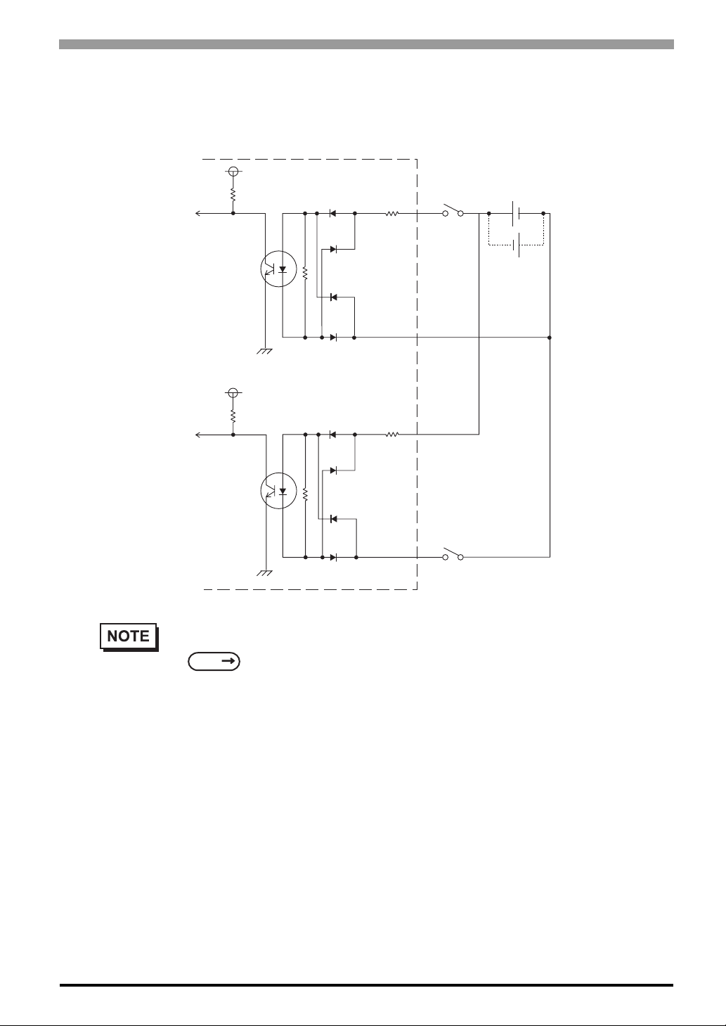
(Interface circuit)
Input part circuit
Input port
Input port
Vcc
R
PC357
Vcc
R
Internal circuit
R
DIN 0(+)
DIN 0(-)
DIN 1(+)
Chapter 6 Monitoring Features
No polar character
for sink source input
DC12V to DC24V
-
+
-
+
PC357
R
DIN 1(-)
• For information concerning the RAS Connector Pin Configuration, refer to the following.
SEE
2.3.2 RAS Interface (page2-8)
6-5
Page 99
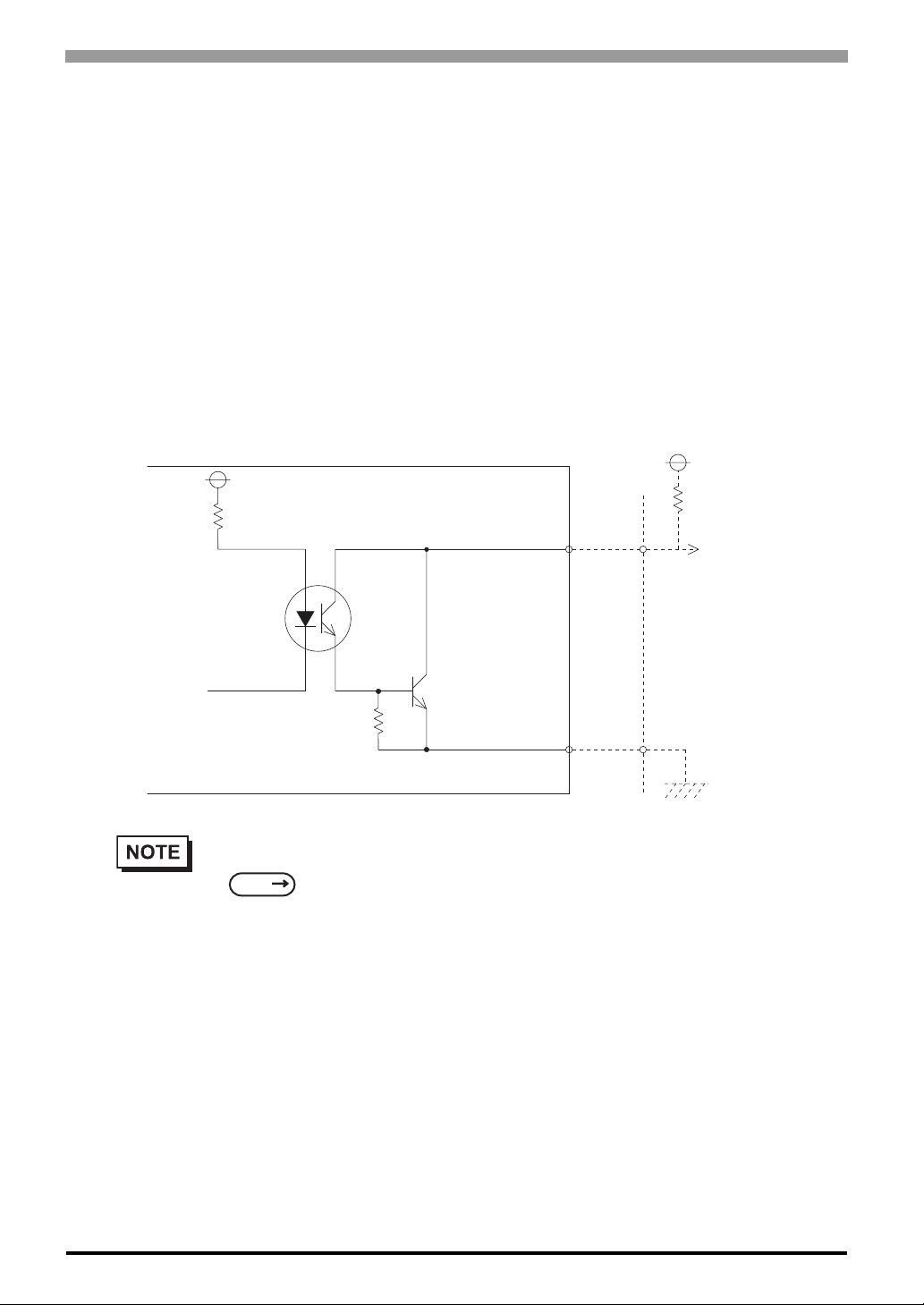
PS-3650A / PS-3651A User Manual
External Output Signals
The RAS interface connector on the PS-A unit is prepared for the following output signals.
General Purpose Signal Output (DOUT 2-bit)
This is a digital output signal for reporting system conditions to external devices. It can be controlled from
applications via either the System Monitor Property, or an API-DLL.
External Output Signals (DOUT)
• Output specifications : DC24V 120mA (MAX)
• Isolation : Used (Photo isolation)
(Interface circuits)
+5V
R
DOUT0(+)
DOUT1(+)
Cable
PC357
SSTA06
DOUT0(-)
DOUT1(-)
4.7KΩ
• For information concerning the RAS Connector Pin Configuration, refer to the following.
SEE
2.3.2 RAS Interface (page2-8)
6-6
Page 100
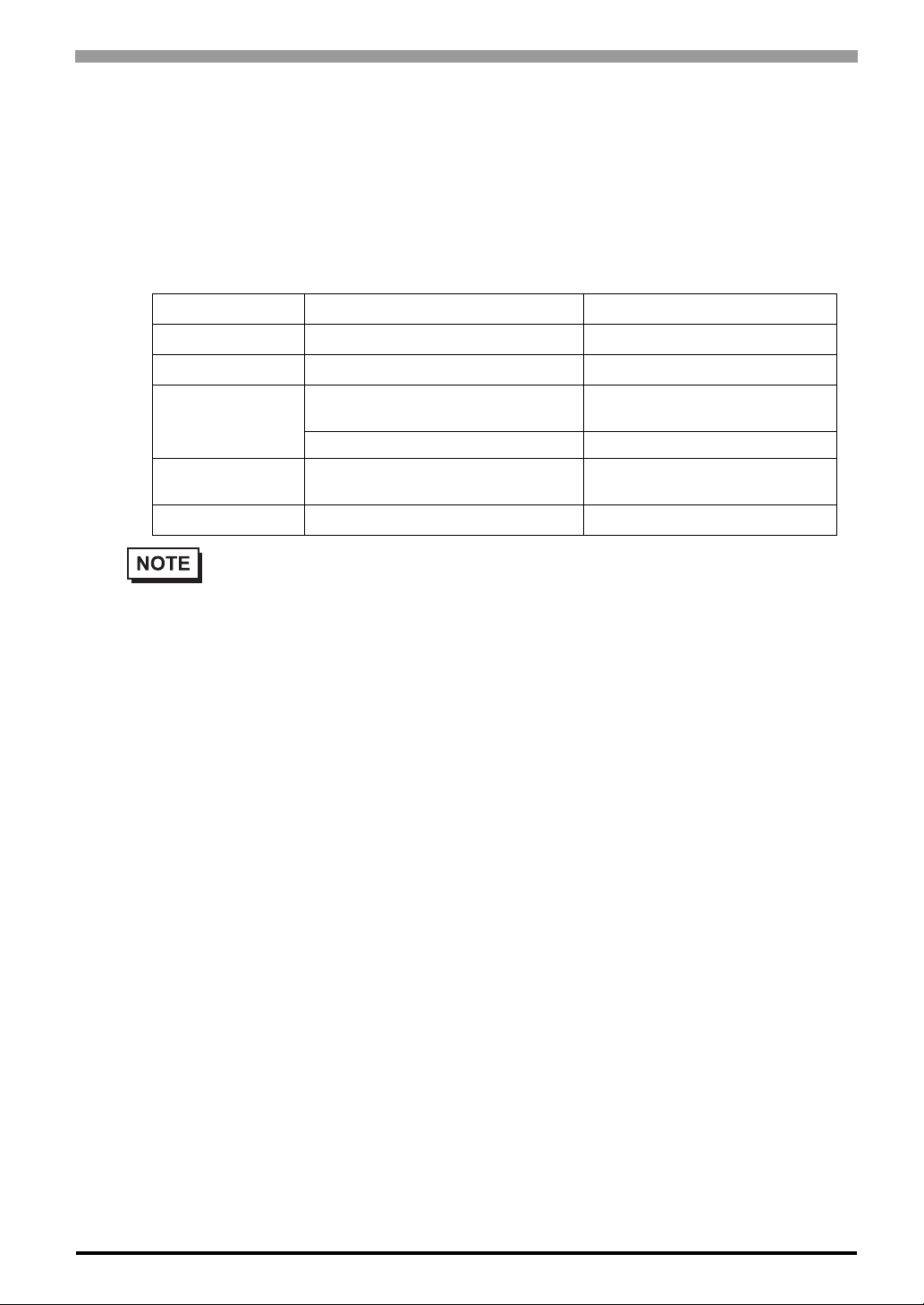
Chapter 6 Monitoring Features
Types of Processing
The PS-A unit can send the following system status information to an external device.
LED Indicator
The three-color LED is used to indicate the PS-A system conditions. It is als o us ed as a power ON/OFF indicator. The LED is located on the front face of the PS-A unit.
LED Color Sys tem Status o utput condition
Green (Lit) Normal Operation (Power is ON) None
Green (Blinking) System is NOT running (Soft OFF) None
Orange (Lit)
Orange/Red
(Blinking)
Not Lit Power is OFF -
A RAS alarm has occurred.
Touch Panel Self -Test Error None
Backlight is not functioning. None
LED is enabled via System
Monitor Property.
• Immediately after the PS-A unit's power is turned ON, if the orange LED lights, a Touch Panel
Self-Test Error may have occurred.
Pop-up Message Output
®
This feature displays system status via a Windows
System Monitor Property is used to enable or disable this feature.
Buzzer Output
This feature uses the PS-A unit’s built-in speaker to alert the operator about the PS-A system status.
System Monitor Property is used to enable or disable this feature.
System Shutdown
This feature shuts down the PS-A unit’s OS.
System Monitor Property is used to enable or disable this feature.
System Reset
This feature resets the system when the Watchdog Timer reaches “time up”.
pop-up message.
System Monitor Property is used to enable or disable this feature.
6-7
 Loading...