

Page 1
Device/PLC Connection
About the Device/PLC Connection Manuals
Prior to reading these manuals and setting up your device, be sure to read the
"Important: Prior to reading the Device/PLC Connection manual" information. Also,
be sure to download the "Preface for Trademark Rights, List of Units Supported, How
to Read Manuals and Documentation Conventions" PDF file. Furthermore, be sure
to keep all manual-related data in a safe, easy-to-find location.
Manuals
Page 2
1
Device Net - Slave I/O
GP-PRO/PBIII for Windows Device/PLC Connection Manual
CPU Link I/F Cable Diagram Link I/F GP
PLC units compatible
with Device Net
Device Net
Master Unit
Cable D iagram 1 Devi ce Net I/F
Unit
(GP070- DN41)
GP Series
*1
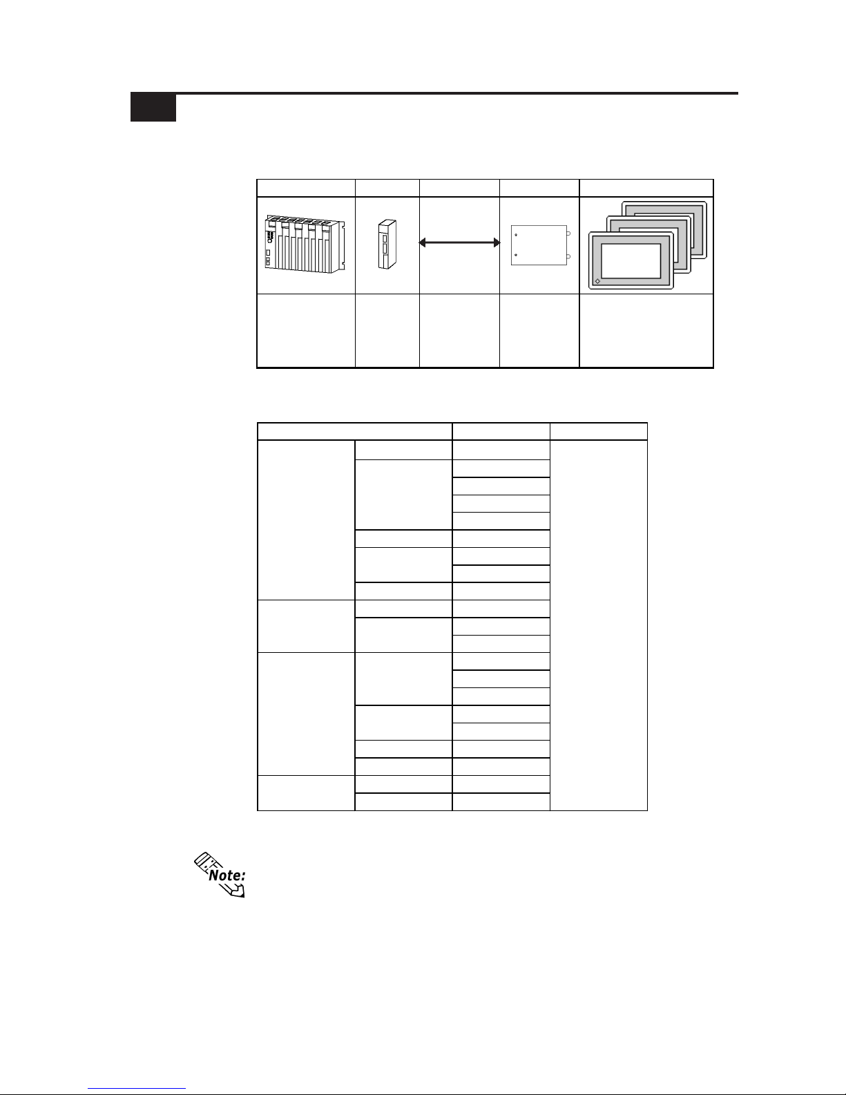
The following table shows the system structure for connecting the GP to PLCs
supporting DeviceNet.
For the cable used, refer to <10.2.2 Cable Diagram>
List of Cables
Dedicated to DeviceNet.
*1 When using GP2000/GLC2000 series units, a bus conversion unit (PSL-
CONV00) is required.
Product Name Unit
GP-470 S eri es GP-470E
GP-570S
GP-570T
GP-57JS
GP-570VM
GP-571 S eri es GP-571T
GP-675S
GP-675T
GP-870 S eri es GP-870V M
GP-477R Series GP-477RE
GP-577RS
GP-577RT
GP-2500L
GP-2500S
GP-2500T
GP-2501S
GP-2501T
GP-2600 Series GP-2600T
GP-2601 Series GP-2601T
GLC2 500 Seri es GLC2500T
GLC2 600 Seri es GLC2600T
DeviceNet Unit
(GP070-DN41)
*1
GP70 S eri es
GP77R Series
GP-570 S eri es
GP-675 S eri es
GP-577R Series
GP-2501 Series
GLC2 000 Seri es
GP2000 Ser i es GP-2500 S eri es
Series Name
*1 The following table lists the GP units that can be connected and used with
DeviceNet.
1 System Structure
Page 3
2
Device Net - Slave I/O
GP-PRO/PBIII for Windows Device/PLC Connection Manual
• Only the LS Area's User Area (from LS20 to LS1999) is used for this
communication.
• The System Area (from LS0 to LS19) and Reading Area settings cannot be
used for PLC communication.
• GP will be used as a slave unit.
• Explicit Message Communication is not supported.
• The Contents in System Area are programless.
Note:
Slave I/O
Slave I/O is the feature that converts I/O data automatically between the PLC installed with the master unit and GP unit.
Slave I/O uses a special link method that does not allow a user to access a PLC
directly .
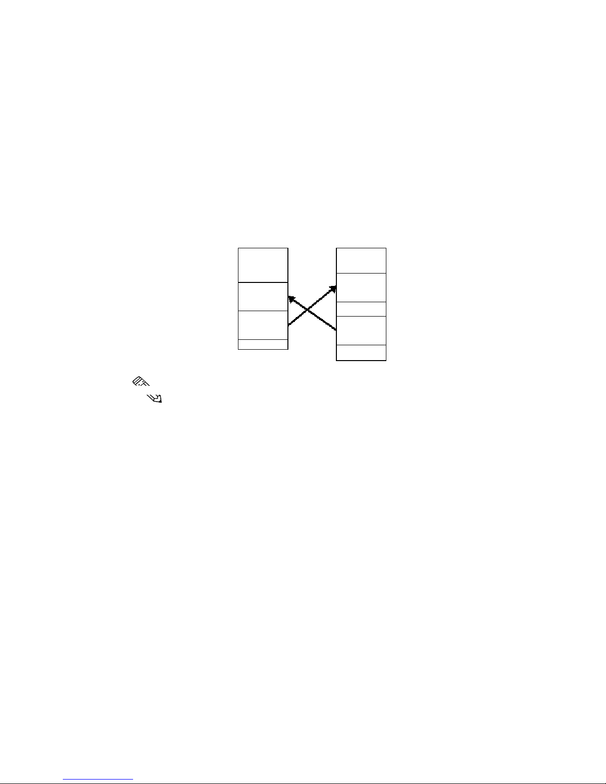
When using Device Net Connection the GP series unit performs like an I/O terminal
(Remote terminal). The GP's LS area will be used as a device which inputs/outputs
data with the host (PLC).
The master (host PLC) unit Output area is allocated to GP's Input area, and the
master's Input area is allocated to GP's Output area. The LS area's Input area is
followed in sequence by the Output area. (See below)
LS
GP LS Area Master (host unit)
Input Area
Input Area
Output Area
Output Area
Page 4
3
Device Net - Slave I/O
GP-PRO/PBIII for Windows Device/PLC Connection Manual
DeviceNet Cable
Set Screws
1
2
3
4
5
Pin No.
Wire Cover
Color
Comment
1 Bl ack Power Supply (V-)
2Blue
Com m uni catio n Data
[Low side] (CAN_L)
3 None Shield
4White
Com m uni catio n Data
[High s i de ] (CAN_H)
5 Red Power Supply (V+)
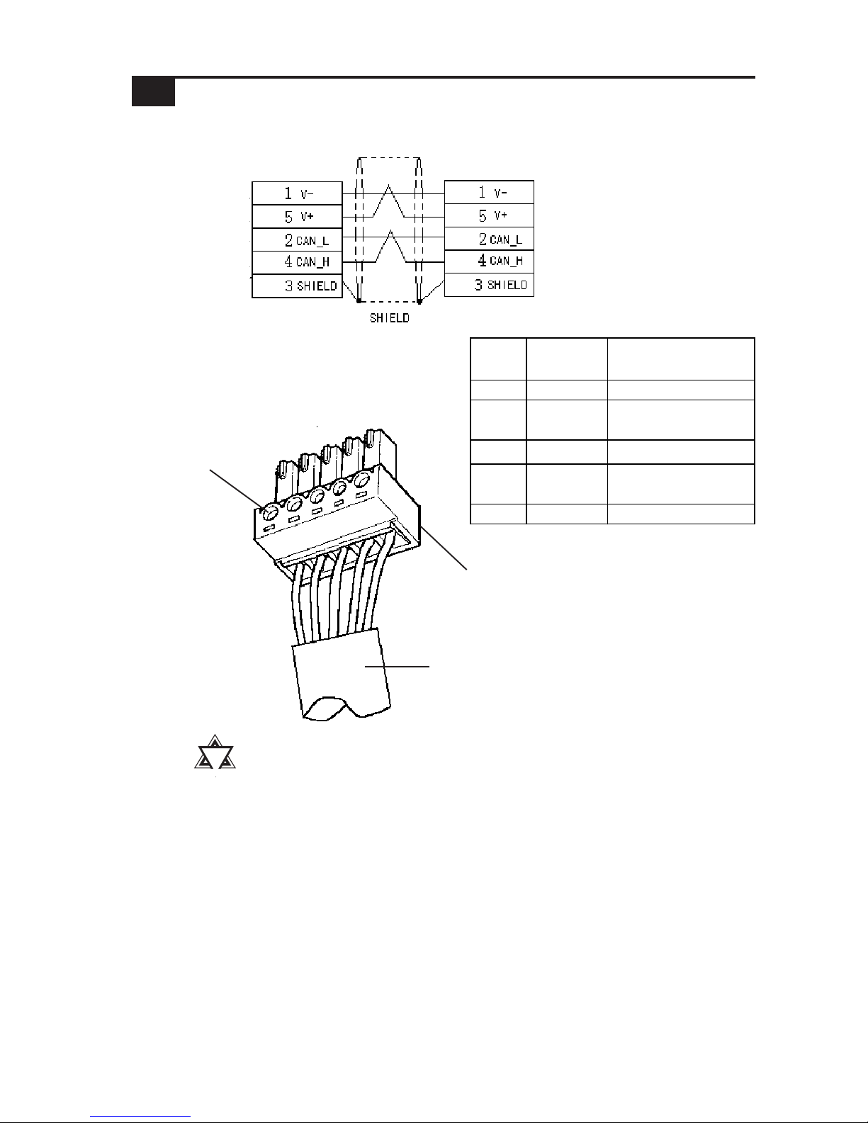
After all connector wires are attached to the connector, connect the connector to the
Device Net I/F Unit (5-wire type).
Be sure to connect T erminating Resistors (121Ω1/4W) to both sides of the cable.
DeviceNet I/F unit attachment
screw connector
GP
PLC or PC (Terminal) or Tap
!!
!!
!
Important
List Device Net Cables
There are two types of cable, thick and thin, for the Device Net unit.
Be sure to use only cables that meet the Device Net specifications. The following
two cables are recommended.
• Rockwell (Allen Bradley) Thick type 1485C-PI-A***
• Rockwell (Allen Bradley) Thin type 1485C-PI-C***
<Cable Diagram 1>
2 Cable Diagrams
Page 5
4
Device Net - Slave I/O
GP-PRO/PBIII for Windows Device/PLC Connection Manual
3 Environment Setup
Enter the GP's communication settings via the SET UP OPERA TION SURROUNDINGS menu.
< GP Example screen >
Input / Output area Settings
c T ouch the INITIALIZE selection.
The INITIALIZE menu will
appear.
The following lists Digital's recommended GP settings.
Baud Rate and Node Number Settings
GP Unit
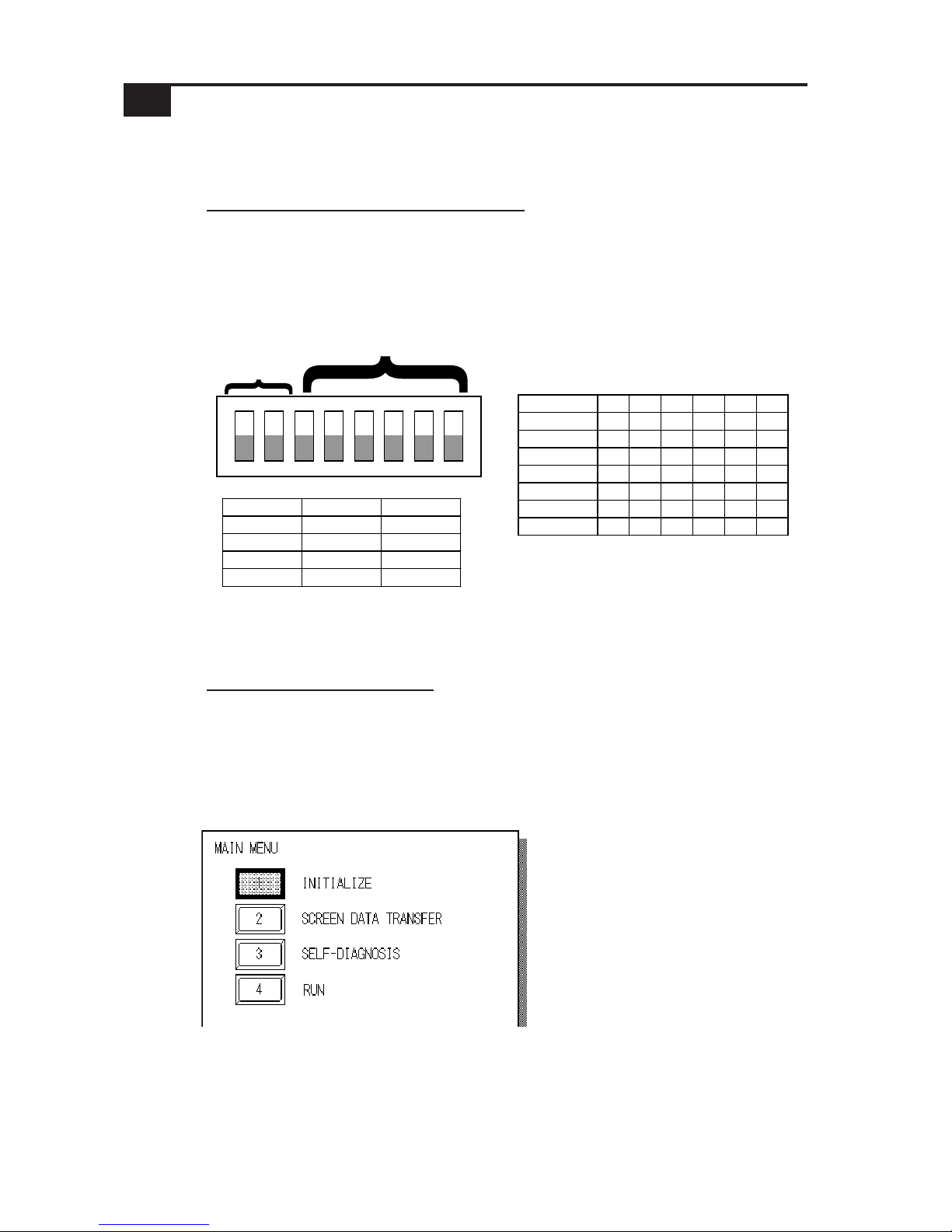
For setting the baud rate and the node number, use the Dip Switch (8 positions) on
the rear side of the Device Net expansion unit (Model: GP070-DN41). The normal
SIO communication setting cannot be used. Node number is available from0 to 63
on the GP .
12345678
Baud Rate
Node Number
Node No.D3D4D5D6D7D8
0 000000
1 000001
2 000010
: ::::::
61 111101
62 111110
63 111111
Baud Rat e DIP S W1 DIP S W2
125K 0 0
250K 0 1
500K 1 0
Reserved 1 1
ON
OFF
PLC Unit
For PLC settings, refer to each company' s Device Net communication unit's manual.
Page 6
5
Device Net - Slave I/O
GP-PRO/PBIII for Windows Device/PLC Connection Manual
The Initialize screen's SET UP I/O area's settings disabled.
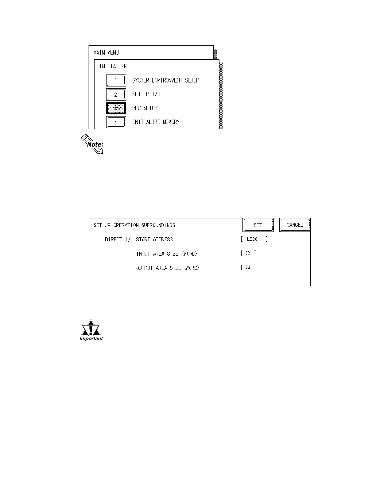
d T ouch the PLC SETUP
selection. The SET UP
OPERA TION SURROUNDINGS
menu will appear.
Enter the following settings to begin I/O communication.
• In the DIO Start Address, enter a value from LS20-LS1999.
• In the Input Area Size, enter a value from 0-127 words.
Set the word area size that is equal to the output area size of the DeviceNet master
unit.
< PLC Settings >
For PLC settings, refer to each company's Device Net communication unit's manual.
The GP’s SYSTEM DATA AREA(LS0 to LS19) cannot be allocated.
• In the Output Area Size, enter a value from 0-127 words.
Set a word area size equal to the input area size of the DeviceNet master unit.
Page 7
6
Device Net - Slave I/O
GP-PRO/PBIII for Windows Device/PLC Connection Manual
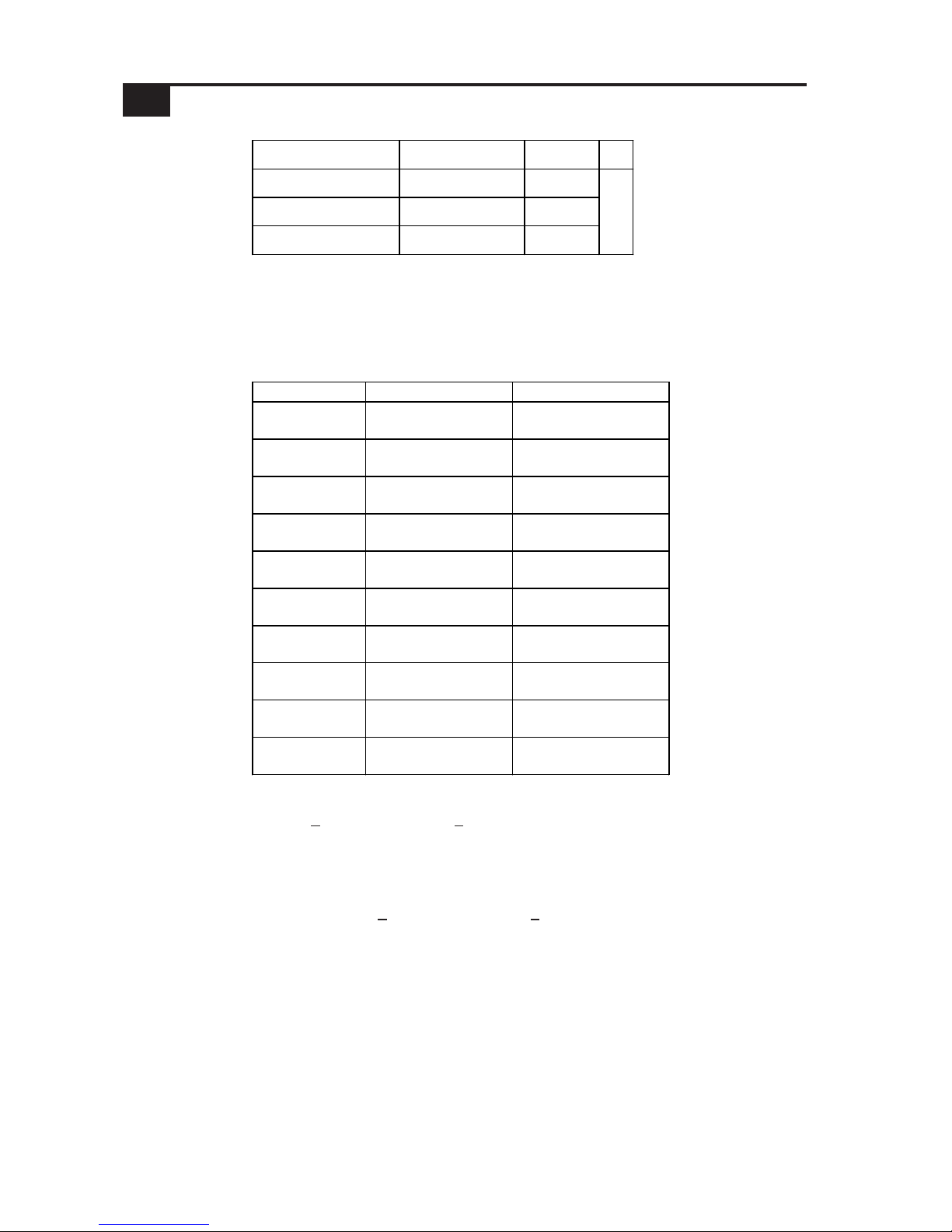
*2 Designate the DIO Start Address within the range shown below.
20
≤
DIO Start Address ≤ 2000 - Input Area Size - Output Area Size
e.g: When Input Area Size =4, and Output Area Size =16,
the setting range of the DIO Start Address should be:
20
≤
DIO Start Address ≤ 1980
PLC Series Input Area Size (word) Output Area Size (word)
Rockwell
SLC500
0 to 64 0 to 64
Rockwell
PLC-5
0 to 64 0 to 64
Rockwell
ControllLogix 5000
0 to 127 0 to 127
Rockwell
MicroLogix 1500
0 to 127 0 to 127
Omron
SYSMAC CS1
0 to 32 o to32
Omron
SYSMAC CJ
0 to 100 o to 100
Omron
SYSMAC CJ1M
0 to 100 o to 100
HITACHI
S10mini
0 to 127 0 to 127
HITACHI
S10V
0 to 127 0 to 127
YOKOGAWA
FA-M3
0 to 127 0 to 127
Word Address Remarks
Input Area Size (word) 0 to 127 *1
Output Area Size (word) 0 to 127 *1
DIO Start Address LS20 to LS1999 *2
L/H
*1 Though the Input /Output area size can be set from 0 to 127, the maximum I/O
size used per slave will differ depending on each company's master unit specifications.
The I/O size that each company supports is shown as below.
4 Supported Devices
Page 8
7
Device Net - Slave I/O
GP-PRO/PBIII for Windows Device/PLC Connection Manual
Error Code Details Status
U nit is not properly installed
Unit Error
Com munication Setting Error
Communic ation Li ne Error
Node No. i s duplicated
14
No reply from the hardware
16
A c om munic ation er r or occurr ed
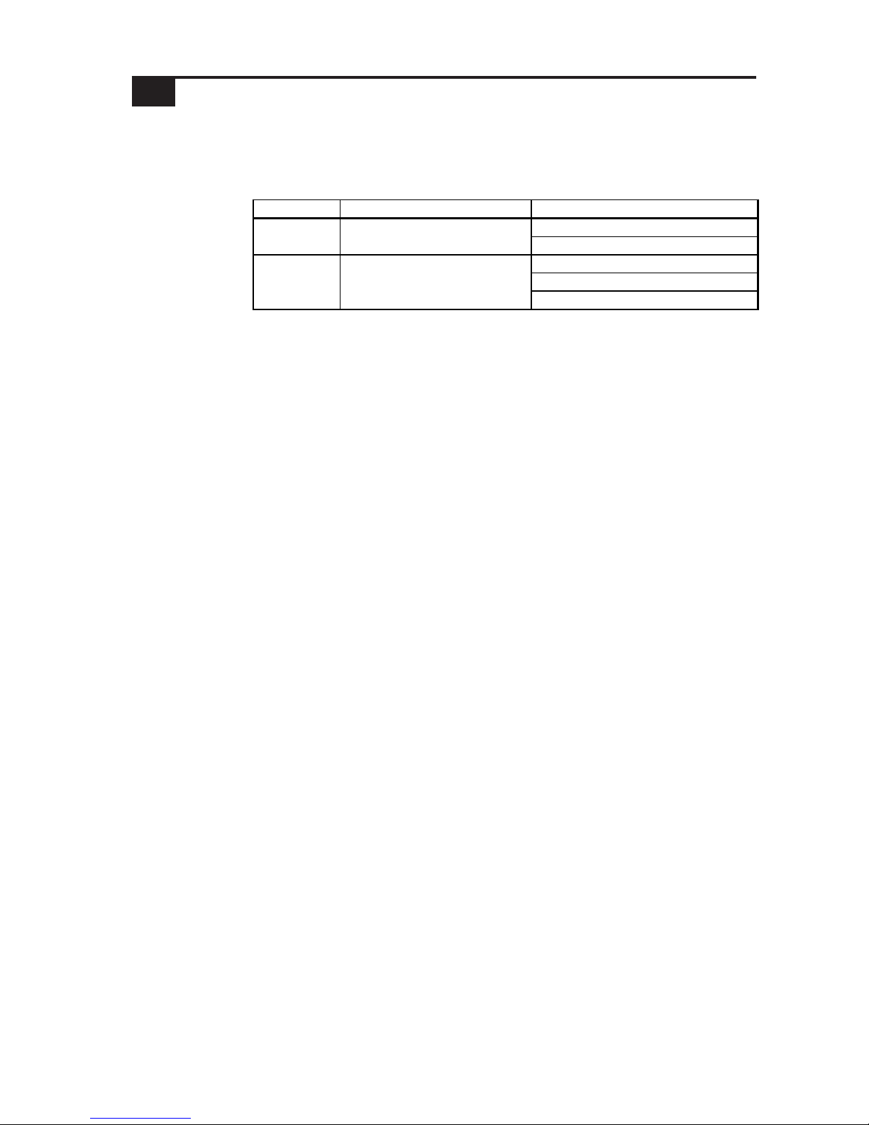
The following list shows the error codes for the Device Net connection. These error
codes will appear as "PLC COM.ERROR (02:**)" on the bottom left on the GP
screen. (** stands for an error code.)
5 Error Codes
 Loading...