

Page 1

FP5000 Series
User Manual
FP5000-MM01-EN-PDF_02
Page 2

The information provided in this documentation contains general descriptions and/or technical
characteristics of the performance of the products contained herein. This documentation is not
intended as a substitute for and is not to be used for determining suitability or reliability of these
products for specific user applications. It is the duty of any such user or integrator to perform the
appropriate and complete risk analysis, evaluation and testing of the products with respect to the
relevant specific application or use thereof. Neither Schneider Electric nor any of its affiliates or
subsidiaries (hereinafter, referred to as Schneider Electric) shall be responsible or liable for misuse
of the information that is contained herein. If you have any suggestions for improvements or
amendments or have found errors in this publication, please notify us.
You agree not to reproduce, other than for your own personal, noncommercial use, all or part of
this document on any medium whatsoever without permission of Schneider Electric, given in
writing. You also agree not to establish any hypertext links to this document or its content.
Schneider Electric does not grant any right or license for the personal and noncommercial use of
the document or its content, except for a non-exclusive license to consult it on an "as is" basis, at
your own risk. All other rights are reserved.
All pertinent state, regional, and local safety regulations must be observed when installing and
using this product. For reasons of safety and to help ensure compliance with documented system
data, only the manufacturer should perform repairs to components.
When devices are used for applications with technical safety requirements, the relevant
instructions must be followed.
Failure to use Schneider Electric software or approved software with our hardware products may
result in injury, harm, or improper operating results.
Failure to observe this information can result in injury or equipment damage.
Copyright © 2017 Schneider Electric Japan Holdings Ltd. All Rights Reserved.
2
Page 3

FP5000 Series User Manual
Table of Contents
Safety Information . . . . . . . . . . . . . . . . . . . . . . . . . . . . . 5
About the Book. . . . . . . . . . . . . . . . . . . . . . . . . . . . . . . . 7
Chapter 1 Overview . . . . . . . . . . . . . . . . . . . . . . . . . . . . . . . . . . . . . 11
Model Number Configuration. . . . . . . . . . . . . . . . . . . . . . . . . . . . . . . .
Model Numbers . . . . . . . . . . . . . . . . . . . . . . . . . . . . . . . . . . . . . . . . . .
Package Contents . . . . . . . . . . . . . . . . . . . . . . . . . . . . . . . . . . . . . . . .
Revision. . . . . . . . . . . . . . . . . . . . . . . . . . . . . . . . . . . . . . . . . . . . . . . .
Certifications and Standards . . . . . . . . . . . . . . . . . . . . . . . . . . . . . . . .
Federal Communication Commission Radio Frequency Interference
Statement - For U.S.A. . . . . . . . . . . . . . . . . . . . . . . . . . . . . . . . . . . . .
Hazardous Location Installation - For USA and Canada. . . . . . . . . . .
European (CE) Compliance. . . . . . . . . . . . . . . . . . . . . . . . . . . . . . . . .
KC Markings . . . . . . . . . . . . . . . . . . . . . . . . . . . . . . . . . . . . . . . . . . . .
Chapter 2 Device Connectivity . . . . . . . . . . . . . . . . . . . . . . . . . . . . 23
System Design . . . . . . . . . . . . . . . . . . . . . . . . . . . . . . . . . . . . . . . . . .
Accessories . . . . . . . . . . . . . . . . . . . . . . . . . . . . . . . . . . . . . . . . . . . . .
Chapter 3 Parts Identification and Functions . . . . . . . . . . . . . . . . 27
FP-5600TPD/5700TPD . . . . . . . . . . . . . . . . . . . . . . . . . . . . . . . . . . . .
LED Indications . . . . . . . . . . . . . . . . . . . . . . . . . . . . . . . . . . . . . . . . . .
Chapter 4 Specifications . . . . . . . . . . . . . . . . . . . . . . . . . . . . . . . . . 31
4.1 General Specifications. . . . . . . . . . . . . . . . . . . . . . . . . . . . . . . . . . . . .
Electrical Specifications. . . . . . . . . . . . . . . . . . . . . . . . . . . . . . . . . . . .
Environmental Specifications . . . . . . . . . . . . . . . . . . . . . . . . . . . . . . .
Structural Specifications . . . . . . . . . . . . . . . . . . . . . . . . . . . . . . . . . . .
4.2 Functional Specifications . . . . . . . . . . . . . . . . . . . . . . . . . . . . . . . . . . .
Display Specifications . . . . . . . . . . . . . . . . . . . . . . . . . . . . . . . . . . . . .
Touch Panel . . . . . . . . . . . . . . . . . . . . . . . . . . . . . . . . . . . . . . . . . . . .
4.3 Interface Specifications . . . . . . . . . . . . . . . . . . . . . . . . . . . . . . . . . . . .
Interface Specifications . . . . . . . . . . . . . . . . . . . . . . . . . . . . . . . . . . . .
Interface Connection . . . . . . . . . . . . . . . . . . . . . . . . . . . . . . . . . . . . . .
DVI-D Input Interface. . . . . . . . . . . . . . . . . . . . . . . . . . . . . . . . . . . . . .
Chapter 5 Dimensions . . . . . . . . . . . . . . . . . . . . . . . . . . . . . . . . . . . 47
FP-5600TPD . . . . . . . . . . . . . . . . . . . . . . . . . . . . . . . . . . . . . . . . . . . .
FP-5700TPD . . . . . . . . . . . . . . . . . . . . . . . . . . . . . . . . . . . . . . . . . . . .
Chapter 6 Installation and Wiring. . . . . . . . . . . . . . . . . . . . . . . . . . 53
6.1 Installation . . . . . . . . . . . . . . . . . . . . . . . . . . . . . . . . . . . . . . . . . . . . . .
Installation Procedures . . . . . . . . . . . . . . . . . . . . . . . . . . . . . . . . . . . .
6.2 Wiring Principles . . . . . . . . . . . . . . . . . . . . . . . . . . . . . . . . . . . . . . . . .
Connecting the DC Power Cord . . . . . . . . . . . . . . . . . . . . . . . . . . . . .
Connecting the Power Supply . . . . . . . . . . . . . . . . . . . . . . . . . . . . . . .
Grounding . . . . . . . . . . . . . . . . . . . . . . . . . . . . . . . . . . . . . . . . . . . . . .
6.3 USB Cable Clamp . . . . . . . . . . . . . . . . . . . . . . . . . . . . . . . . . . . . . . . .
USB Clamp (Type B) . . . . . . . . . . . . . . . . . . . . . . . . . . . . . . . . . . . . . .
12
13
14
15
16
18
19
21
22
24
25
28
29
32
33
34
35
37
38
39
40
41
42
45
48
50
54
54
61
62
64
66
67
67
3
Page 4

6.4 Front USB Cover . . . . . . . . . . . . . . . . . . . . . . . . . . . . . . . . . . . . . . . . .
Opening the Front USB Cover. . . . . . . . . . . . . . . . . . . . . . . . . . . . . . .
70
70
Chapter 7 System Specifications and Launcher. . . . . . . . . . . . . . 73
7.1 System Specifications . . . . . . . . . . . . . . . . . . . . . . . . . . . . . . . . . . . . .
Operating System, Drivers, Utilities. . . . . . . . . . . . . . . . . . . . . . . . . . .
Settings Workflow . . . . . . . . . . . . . . . . . . . . . . . . . . . . . . . . . . . . . . . .
Installing the Drivers . . . . . . . . . . . . . . . . . . . . . . . . . . . . . . . . . . . . . .
Installing the Utilities . . . . . . . . . . . . . . . . . . . . . . . . . . . . . . . . . . . . . .
7.2 Launcher . . . . . . . . . . . . . . . . . . . . . . . . . . . . . . . . . . . . . . . . . . . . . . .
About the Launcher . . . . . . . . . . . . . . . . . . . . . . . . . . . . . . . . . . . . . . .
Display Settings. . . . . . . . . . . . . . . . . . . . . . . . . . . . . . . . . . . . . . . . . .
PC Settings . . . . . . . . . . . . . . . . . . . . . . . . . . . . . . . . . . . . . . . . . . . . .
74
75
76
77
79
80
81
83
87
Chapter 8 Maintenance . . . . . . . . . . . . . . . . . . . . . . . . . . . . . . . . . . 89
Regular Cleaning. . . . . . . . . . . . . . . . . . . . . . . . . . . . . . . . . . . . . . . . .
Periodic Check Points . . . . . . . . . . . . . . . . . . . . . . . . . . . . . . . . . . . . .
Replacing the Installation Gasket . . . . . . . . . . . . . . . . . . . . . . . . . . . .
Replacing the Backlight . . . . . . . . . . . . . . . . . . . . . . . . . . . . . . . . . . . .
Troubleshooting Checklist . . . . . . . . . . . . . . . . . . . . . . . . . . . . . . . . . .
After-sales Service . . . . . . . . . . . . . . . . . . . . . . . . . . . . . . . . . . . . . . .
90
91
92
93
94
95
4
Page 5
Safety Information
Important Information
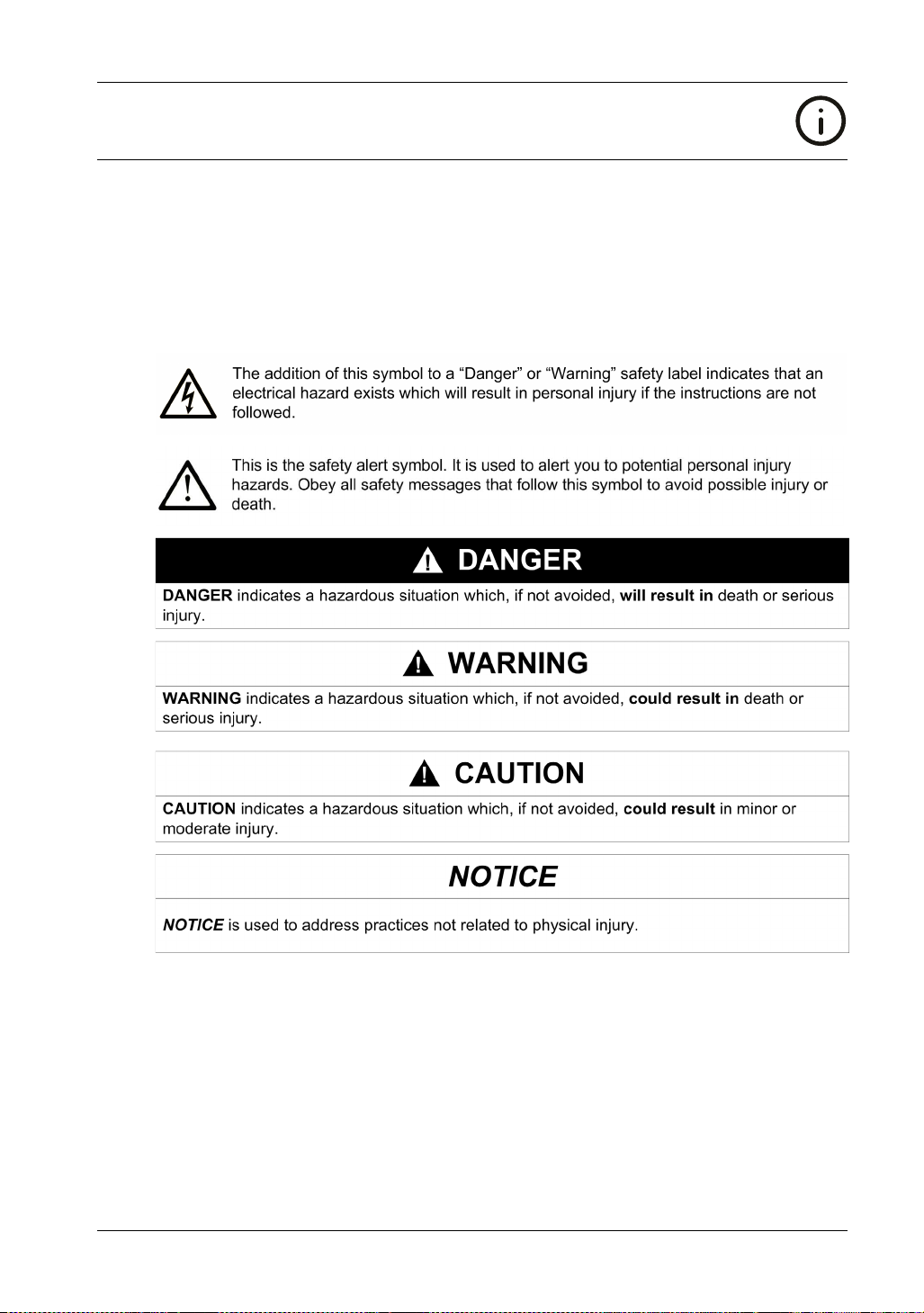
NOTICE
Read these instructions carefully, and look at the equipment to become familiar with the device
before trying to install, operate, or maintain it. The following special messages may appear
throughout this documentation or on the equipment to warn of potential hazards or to call attention
to information that clarifies or simplifies a procedure.
FP5000 Series User Manual
PLEASE NOTE
Electrical equipment should be installed, operated, serviced, and maintained only by qualified
personnel. No responsibility is assumed by Schneider Electric for any consequences arising out of
the use of this material.
A qualified person is one who has skills and knowledge related to the construction and operation
of electrical equipment and its installation, and has received safety training to recognize and avoid
the hazards involved.
5
Page 6

6
Page 7
About the Book
At a Glance
Document Scope
This manual describes how to use this product.
Validity Note
This documentation is valid for this product.
The technical characteristics of the device(s) described in this manual also appear online at
http://www.pro-face.com.
The characteristics presented in this manual should be the same as those that appear online. In
line with our policy of constant improvement we may revise content over time to improve clarity and
accuracy. In the event that you see a difference between the manual and online information, use
the online information as your reference.
Registered Trademarks
Microsoft and Windows are registered trademarks of Microsoft Corporation in the United States
and/or other countries.
Product names used in this manual may be the registered trademarks owned by the respective
proprietors.
FP5000 Series User Manual
Related Documents
You can download the manuals related to this product, such as the software manual, from our
support site at http://www.pro-face.com/trans/en/manual/1001.html.
Product Related Information
HAZARD OF ELECTRIC SHOCK, EXPLOSION, OR ARC FLASH
Remove all power from the device before removing any covers or elements of the system, and
prior to installing or removing any accessories, hardware, or cables.
Unplug the power cable form both this product and the power supply.
Always use a properly rated voltage sensing device to confirm power is off.
Replace and secure all covers or elements of the system before applying power to this
product.
This product uses 12 to 24 Vdc power. Using any other level of power can damage both the
power supply and this product.
Failure to follow these instructions will result in death or serious injury.
Critical alarm indicators and system functions require independent an redundant protection
hardware and/or mechanical interlocks.
When you cycle power, wait at least 10 seconds after it has been turned off. If this product is
restarted too quickly, it may not operate correctly.
DANGER
7
Page 8
In the event the screen cannot be properly read, for example, if the backlight is not functioning, it
may be difficult or impossible to identify a function. Functions that may present a hazard if not
immediately executed, such as a fuel shut-off, must be provided independently of this product. The
machine’s control system design must take into account the possibility of the backlight no longer
functioning and the operator being unable to control the machine or making mistakes in the control
of the machine.
WARNING
LOSS OF CONTROL
The designer of any control scheme must consider the potential failure modes of control paths
and, for certain critical control functions, provide a means to achieve a safe state during and
after a path failure. Examples of critical control functions are emergency stop and overtravel
stop, power outage and restart.
Separate or redundant control paths must be provided for critical control functions.
System control paths may include communication links. Consideration must be given to the
implications of unanticipated transmission delays or failures of the link.
Observe all accident prevention regulations and local safety guidelines.
Each implementation of this product must be individually and thoroughly tested for proper
operation before being placed into service.
The machine control system design must take into account the possibility of the backlight no
longer functioning and the operator being unable to control the machine, or making errors in
the control of the machine.
Failure to follow these instructions can result in death, serious injury, or equipment
damage.
For additional information, refer to NEMA ICS 1.1 (latest edition), "Safety Guidelines for the
Application, Installation, and Maintenance of Solid State Control" and to NEMA ICS 7.1 (latest
edition), "Safety Standards for Construction and Guide for Selection, Installation and Operation of
Adjustable-Speed Drive Systems" or their equivalent governing your particular location.
WARNING
UNINTENDED EQUIPMENT OPERATION
The application of this product requires expertise in the design and programming of control
systems. Only persons with such expertise should be allowed to program, install, alter, and apply
this product.
Follow all local and national safety standards.
Failure to follow these instructions can result in death, serious injury, or equipment
damage.
8
Page 9

FP5000 Series User Manual
WARNING
UNINTENDED EQUIPMENT OPERATION
Do not use this product as the only means of control for critical system functions such as motor
start/stop or power control.
Do not use this equipment as the only notification device for critical alarms, such as device
overheating or overcurrent.
Use only the software provided with this product. If you use another software, please confirm
the operation and safety before use.
Failure to follow these instructions can result in death, serious injury, or equipment
damage.
The following characteristics are specific to the LCD panel and are considered normal behavior:
LCD screen may show unevenness in the brightness of certain images or may appear different
when seen from outside the specified viewing angle. Extended shadows, or crosstalk may also
appear on the sides of screen images.
LCD screen pixels may contain black and white colored spots and color display may seem to
have changed.
When the same image is displayed on the screen for a long period, an afterimage may appear
when the image is changed.
The panel brightness may decrease when used for a long time in an environment continuously
filled with inert gas. To prevent deterioration of panel brightness, regularly ventilate the panel.
For more information, please contact customer support.
http://www.pro-face.com/trans/en/manual/1015.html
NOTE: Change the screen image periodically and try not to display the same image for a long
period of time.
CAUTION
SERIOUS EYE AND SKIN INJURY
The liquid in the LCD panel contains an irritant:
Avoid direct skin contact with the liquid.
Wear gloves when you handle a broken or leaking unit.
Do not use sharp objects or tools in the vicinity of the LCD panel.
Handle the LCD panel carefully to prevent puncture, bursting, or cracking of the panel material.
If the panel is damaged and any liquid comes in contact with your skin, immediately rinse the
area with running water for at least 15 minutes. If the liquid gets in your eyes, immediately rinse
your eyes with running water for at least 15 minutes and consult a doctor.
Failure to follow these instructions can result in injury or equipment damage.
9
Page 10

10
Page 11
FP5000 Series User Manual
Overview
iDisplay_PF 12/2017
Overview
Chapter 1
Overview
Introduction
This chapter describes the panels of this product and general topics such as package contents and
standards.
What Is in This Chapter?
This chapter contains the following topics:
Model Number Configuration 12
Model Numbers 13
Package Contents 14
Revision 15
Certifications and Standards 16
Federal Communication Commission Radio Frequency Interference Statement - For U.S.A. 18
Hazardous Location Installation - For USA and Canada 19
European (CE) Compliance 21
KC Markings 22
FP5000 Series User Manual
Topic Page
11
Page 12

Overview
Model Number Configuration
The following describes the configuration of model numbers.
Digit position 1 2 3 4 5 6 7 8 9 10 11 12
P F X (model) (series) (size) (type) (LCD) (touch
FP 5 6: 12.1-inch
7: 15-inch
00: Standard T: TFT P: Multi D: DC
panel)
(power
supply)
12
Page 13

Model Numbers
Series Display size Model names Model numbers
FP5000 Series 12.1-inch FP-5600TPD PFXFP5600TPD
Global Code
A global code is assigned to every Pro-face product as a universal model number. For more
information on product models and their matching global codes, please refer to the following URL.
http://www.pro-face.com/trans/en/manual/1003.html
FP5000 Series User Manual
15-inch FP-5700TPD PFXFP5700TPD
13
Page 14
Overview
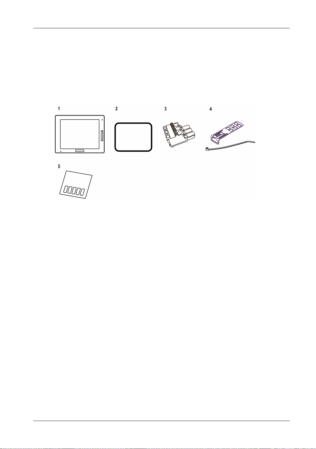
Package Contents
NOTE: This product has been carefully packed with special attention to quality. However, should
you find anything damaged or missing, please contact customer support immediately.
Verify all items listed here are present in your package:
1 FP5000 Series: 1
2 Installation gasket: 1 (attached to this product)
3 DC power supply connector (right angle): 1
4 USB clamp (Type B): 1 set (1 clip and 1 tie)
5 USB masking sticker (mini-B)
6 FP5000 Series Installation Guide: 1
7 Warning/Caution Information: 1
*1
: 1
*1 See Parts Identification and Functions (see page 27).
14
Page 15
Revision
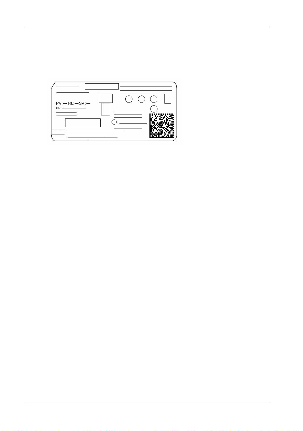
You can identify the product version (PV), revision level (RL), and the software version (SV) from
the product label.
FP5000 Series User Manual
15
Page 16

Overview
Certifications and Standards
NOTE: Some products are not subject to certification and standards. And some products have not
received their certification and standards but are scheduled for assessment.
For information on certifications and standards, such as certified models and certificates, see the
product markings or the following URL:
http://www.pro-face.com/trans/en/manual/1002.html
Agency Certifications
Schneider Electric submitted this product for independent testing and qualification by third-party
listing agencies. These agencies have certified this product as meeting the following standards.
Underwriters Laboratories Inc., UL 508 and CSA C22.2 N
Underwriters Laboratories Inc., ANSI/ISA 12.12.01 and CSA C22.2 N
Equipment for Use in Class I, Division 2 Hazardous (Classified) Locations
IECEx/ATEX for use in zones 2/22
GOST-R or EAC certification (Russia, Belarus, Kazakhstan)
Germanischer Lloyd (GL)
Compliance Standards
Europe:
CE
Directive 2014/35/EU (Low Voltage)
Directive 2014/30/EU (EMC)
Programmable Controllers: EN 61131-2
EN61000-6-4
EN61000-6-2
Directive 94/9/EC (ATEX)
EN60079-0
EN60079-15
EN60079-31
Australia
RCM Mark
EN61000-6-4
Korea
KC Markings
KN11
KN61000-6-2
o
142, Industrial Control Equipment
o
213, Electrical
Qualifications Standards
Schneider Electric voluntarily tested this product to additional standards. The additional tests
performed, and the standards under which the tests were conducted, are specifically identified in
Structural Specifications (see page 35).
16
Page 17

Hazardous Substances
This product is a device for use in factory systems. When using this product in a system, the system
should comply with the following standards in regards to the installation environment and handling:
WEEE, Directive 2012/19/EU
RoHS, Directive 2011/65/EU
RoHS China, Standard GB/T 26572
REACH regulation EC 1907/2006
FP5000 Series User Manual
17
Page 18
Overview
Federal Communication Commission Radio Frequency Interference Statement For U.S.A.
FCC Radio Interference Information
This product has been tested and found to comply with the Federal Communications Commission
(FCC) limits for a Class A digital device, pursuant to Part 15 of the FCC Rules. These limits are
designed to provide reasonable protection against harmful interference in a commercial, industrial
or business environment. This product generates, uses, and can radiate radio frequency energy
and, if not installed and used in accordance with the instructions, may cause or be subject to
interference with radio communications. To minimize the possibility of electromagnetic interference
in your application, observe the following two rules:
Install and operate this product in such a manner that it does not radiate sufficient
electromagnetic energy to cause interference in nearby devices.
Install and test this product to ensure that the electromagnetic energy generated by nearby
devices does not interfere with the operation of this product.
WARNING
ELECTROMAGNETIC / RADIO INTERFERENCE
Electromagnetic radiation may disrupt the operation of this product leading to unintended
equipment operation. If electromagnetic interference is detected:
Increase the distance between this product and the interfering equipment.
Reorient this product and the interfering equipment.
Reroute power and communication lines to this product and the interfering equipment.
Connect this product and the interfering equipment to different power supplies.
Always use shielded cables when connecting this product to a peripheral device or another
computer.
Changes or modifications not expressly approved by the party responsible for compliance
could void the user’s authority to operate this product.
Failure to follow these instructions can result in death, serious injury, or equipment
damage.
18
Page 19

Hazardous Location Installation - For USA and Canada
General
This product has been designed with the intention of meeting the requirements of Class I, Division
2 hazardous location application. Division 2 locations are those locations where ignitable
concentrations of flammable substances are normally confined, prevented by ventilation, or
present in an adjacent Class I, Division 1 location, but where an abnormal situation might result in
intermittent exposure to such ignitable concentrations.
While this product is a non-incendive device under ANSI/ISA 12.12.01 and CSA C22.2 N213, it is
not designed for, and should never be used within a Division 1 (normally hazardous) location.
This product is suitable for use in Class I, Division 2, Groups A, B, C, and D hazardous locations
or in non-hazardous locations. Before installing or using this product, confirm that the ANSI/ISA
12.12.01 or CSA22.2 N213 certification appears on the product labeling.
NOTE: Some products are not yet rated as suitable for use in hazardous locations. Always use
your product in conformance with the product labeling and this manual.
DANGER
POTENTIAL FOR EXPLOSION
Do not use this product in hazardous environments or locations other than Class I, Division2,
Group A, B, C, and D.
Substitution of any component may impair suitability for Class I, Division 2.
Do not connect or disconnect this product unless power has been switched off or the area is
known to be non-hazardous.
Always confirm that this product is suitable for use in hazardous locations by checking the
ANSI/ISA 12.12.01 or CSA C22.2 N213 certification appears on the product labeling.
Do not install any Pro-face or OEM components, equipment, or accessories unless these have
also been qualified as suitable for use in Class I, Division 2, Groups A, B, C, and D locations.
Do not attempt to install, operate, modify, maintain, service, or otherwise alter this product
except as permitted in this manual. Unpermitted actions may impair the suitability of this
product for Class I, Division 2 operation.
Failure to follow these instructions will result in death or serious injury.
FP5000 Series User Manual
DANGER
POTENTIAL FOR EXPLOSION
Always confirm the ANSI/ISA 12.12.01 or CSA C22.2 N213 hazardous location rating of your
device before installing or using it in a hazardous location.
To apply or remove the supply power from this product installed in a Class I, Division 2
hazardous location, you must either:
Use a switch located outside the hazardous environment, or;
Use a switch certified for Class I, Division 1 operation inside the hazardous area.
Do not connect or disconnect equipment unless power has been switched off or the area is
known to be non-hazardous. This applies to all connections including power, ground, serial,
parallel, and network connections.
Never use unshielded / ungrounded cables in hazardous locations.
Use only non-incendiary USB devices.
When enclosed, keep enclosure doors and openings closed at all times to avoid the
accumulation of foreign matter inside the workstation.
Failure to follow these instructions will result in death or serious injury.
19
Page 20

Overview
HAZARD OF ELECTRIC SHOCK, EXPLOSION, OR ARC FLASH
Remove all power from the device before removing any covers or elements of the system, and
prior to installing or removing any accessories, hardware, or cables.
Unplug the power cable form both this product and the power supply.
Always use a properly rated voltage sensing device to confirm power is off.
Replace and secure all covers or elements of the system before applying power to this
product.
Use only the specified voltage when operating this product. The DC unit is designed to use 12
to 24 Vdc. Always check whether your device is AC or DC powered before applying power.
Failure to follow these instructions will result in death or serious injury.
Make sure that this product is properly rated for the location. If the intended location does not
presently have a Class, Division and Group rating, then users should consult the appropriate
authorities having jurisdiction in order to determine the correct rating for that hazardous location.
Operation and Maintenance
The systems have been designed for compliance with relevant spark ignition tests.
DANGER
DANGER
POTENTIAL FOR EXPLOSION
In addition to the other instructions in this manual, observe the following rules when installing this
product in a hazardous location:
Wire the equipment in accordance with the National Electrical Code article 501.10 (B) for
Class I, Division 2 hazardous locations.
Install this product in an enclosure suitable for the specific application. IP65F, IP66F, IP67F,
Type 1, Type 4X [Indoor Use Only], or Type 13 enclosures are recommended even when not
required by regulations.
Failure to follow these instructions will result in death or serious injury.
NOTE: IP65F, IP66F and IP67F are not part of UL certification.
20
Page 21

European (CE) Compliance
CE Compliance Note
The product described in this manual comply with the European Directives concerning
Electromagnetic Compatibility and Low Voltage (CE marking) when used as specified in the
relevant documentation, in application for which they are specifically intended, and in connection
with approved third-party products.
FP5000 Series User Manual
21
Page 22

Overview
KC Markings
22
Page 23

FP5000 Series User Manual
Device Connectivity
iDisplay_PF 12/2017
Device Connectivity
Chapter 2
Device Connectivity
Introduction
This chapter presents the equipment you can connect to this product.
What Is in This Chapter?
This chapter contains the following topics:
System Design 24
Accessories 25
FP5000 Series User Manual
Topic Page
23
Page 24

Device Connectivity
System Design
24
*1 For image signal reception.
*2 Refer to Accessories (see page 25).
*3 You can also use a commercial type.
*4 For touch panel data transmission.
*5 When you connect a USB (Type B) interface to the host with a USB cable, you can use the front
USB (Type A) interface.
*6 You can use Pro-face products. Refer to our website (http://www.pro-face.com).
NOTE: When you connect more than one display to the host in the following combinations, a touch
operation on one display prevents touch operations on the other.
This Product + This Product
This Product + SP5000 Series Display Module
Be careful when you connect displays in any other combination, as touch operations become
possible from any of the displays.
Page 25

Accessories
Product name Product number Description
USB Cable (5 m)
USB (Type B) Interface
DVI-D Cable (5 m)
DVI-D Input Interface
12.1-inch Screen Protection Sheet CA7-DFS12-01 Disposable, dirt-resistant sheet for the display
15-inch Screen Protection Sheet CA3-DFS15-01
12.1-inch Environment Cover PFXZCDOP121 Environmental resistant cover for the display
15-inch Environment Cover PFXZCDOP151
Enhanced Front USB Cover (With
Screw)
DC Power Supply Connector
(Straight)
FP5000 Series User Manual
*1
FP-US00 Cable used for touch panel data transmission
between a host (USB Type A) and this product
(USB Type B).
*1
FP-DV01-50 DVI-D cable used to receive the image signal from
host.
DVI 1.0 compliant (DVI-D 24-pin plug) (5 m).
(5 sheets/set)
(1 piece)
PFXZCDCVUS1 Front USB cover with fixing screw, corresponding
to IP66F, IP67F, Type 1/4X Indoor Use Only/13 or
ATEX certifications (5 pieces/set)
PFXZCBCNDC1 Connector to connect DC power supply cables
(5 pcs/set)
*1 You can also use a commercial type.
Maintenance Accessories
Product name Product number Description
12.1-inch Installation Gasket PFXZCDWG121 Provides dust and moisture resistance when this
15-inch Installation Gasket PFXZCDWG151
DC Power Supply Connector
PFXZCBCNDC2 Right-angle connector to connect DC power
(Right-angle)
USB Clamp (Type B) PFXZFP5000USCLB1 Clamp to prevent disconnection of USB cable
25
product is installed into a solid panel (1 piece)
supply cables (5 pcs/set)
(USB/Type B, 1 port, 5 clamps/set).
Page 26

Device Connectivity
26
Page 27
FP5000 Series User Manual
Parts Identification and Functions
iDisplay_PF 12/2017
Parts Identification and Functions
Chapter 3
Parts Identification and Functions
Introduction
This chapter presents the part locations and functions.
What Is in This Chapter?
This chapter contains the following topics:
FP-5600TPD/5700TPD 28
LED Indications 29
FP5000 Series User Manual
Topic Page
27
Page 28

Parts Identification and Functions
FP-5600TPD/5700TPD
NOTE: The figures below show FP-5600TPD.
Side FP-5600TPD/5700TPD
Front
Rear
28
Bottom
Part Name Description
A Brightness sensor Brightness sensor that automatically controls the
brightness of the backlight.
B Front USB cover USB (Type A) interface is located behind the front
USB cover.
C Front USB (Type A)
interface
D USB masking sticker
(mini-B)
E Status LED (see page 29)
F Power connector –
G DVI-D input interface DVI-D input interface
H USB (Type B) interface Conforms to USB 2.0 (Type B) x 1.
Conforms to USB 2.0 (Type A) x 1.
You cannot use the USB (mini-B) interface. Affix
the provided USB masking sticker.
Page 29

LED Indications
Status LED
Color Indicator Description
Green ON In operation
Green/Orange Alternating Launcher is being configured (see page 81)
Orange Flashing Software is starting up
Red ON Power is turned ON
Orange/Red/Green Alternating
– OFF Power is turned OFF
*1 The product may be malfunctioning. Please contact customer support.
NOTE: If the screen does not display and the status LED is not in the LED fade state, this indicates
the backlight is burned out. When the screen does not display, always check the LED status and
do not perform touch operations.
FP5000 Series User Manual
LED fade Backlight is OFF (Standby Mode), or no video input
signal
Display unit error
*1
29
Page 30

Parts Identification and Functions
30
Page 31
FP5000 Series User Manual
Specifications
iDisplay_PF 12/2017
Specifications
Chapter 4
Specifications
Introduction
This chapter presents the product specifications.
What Is in This Chapter?
This chapter contains the following sections:
Section Topic Page
4.1 General Specifications 32
4.2 Functional Specifications 37
4.3 Interface Specifications 40
FP5000 Series User Manual
31
Page 32

Specifications
General Specifications
Section 4.1
General Specifications
What Is in This Section?
This section contains the following topics:
Electrical Specifications 33
Environmental Specifications 34
Structural Specifications 35
Topic Page
32
Page 33
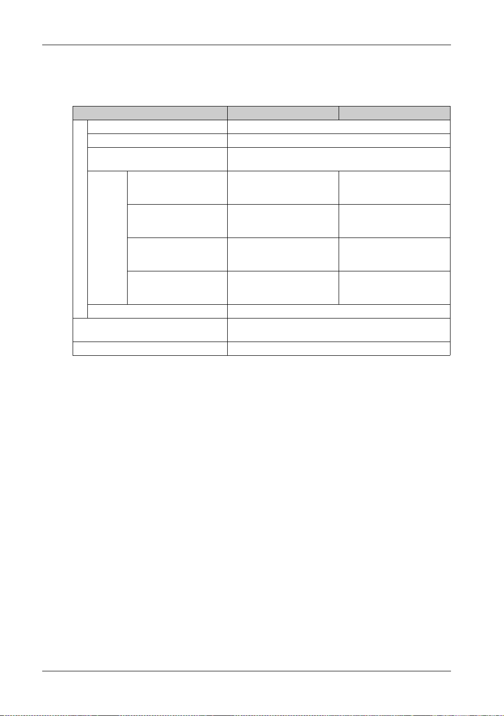
Electrical Specifications
Specification FP-5600TPD FP-5700TPD
Rated input voltage 12...24 Vdc
Input voltage limits 10.8...28.8 Vdc
Voltage drop 12 Vdc: 2.5 ms or less
Backlight ON: 100%
(Power is supplied to
external devices)
Backlight ON: 100%
(Power is not supplied to
Power supply
Power consumption
In-rush current 30 A or less
Voltage endurance 1,000 Vac, 20 mA for 1 minute (between charging and FG
Insulation resistance 500 Vdc, 10 M or more (between charging and FG terminals)
external devices)
Backlight adjusted: 20%
(Power is not supplied to
external devices)
including power loss)
(primary power supply
Backlight OFF
(Power is not supplied to
external devices)
FP5000 Series User Manual
24 Vdc: 10 ms or less
17 W or less 21 W or less
14 W or less 18 W or less
9 W or less 11 W or less
7W or less 8W or less
terminals)
33
Page 34
Specifications
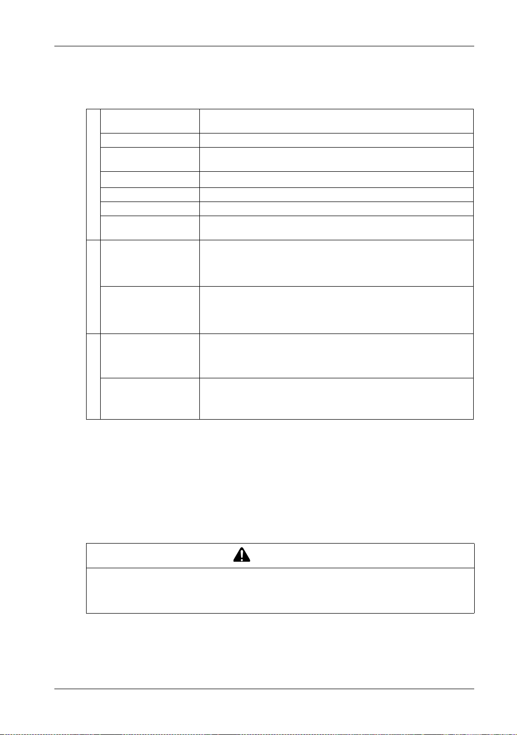
Environmental Specifications
Surrounding air
temperature
Storage temperature -20...60 C (-4...140 F)
Surrounding air and
storage humidity
Dust
Pollution degree For use in Pollution Degree 2 environment
Corrosive gases Free of corrosive gases
Physical environment
Atmospheric pressure
(operating altitude)
Vibration resistance IEC/EN 61131-2 compliant
Shock resistance IEC/EN 61131-2 compliant
Mechanical environment
Noise immunity Noise voltage: 1,000 Vp-p
Electrostatic discharge
immunity
0...60 C (32...140 F)
10%...90% RH (non-condensing, wet bulb temperature 39 C [102.2 F] or
less)
3
0.1 mg/m
800...1,114 hPa (2,000 m [6,561 ft] or lower)
5...9 Hz single amplitude 3.5 mm (0.14 in)
9...150 Hz fixed acceleration: 9.8 m/s
X, Y, Z directions for 10 cycles (approx. 100 min.)
147 m/s
Pulse duration: 1 s
Rise time: 1 ns
(via noise simulator)
Contact discharge method: 6 kV (IEC/EN 61000-4-2 Level 3)
(10-7 oz/ft3) or less (non-conductive levels)
2
, X, Y, Z directions for 3 times
2
Electrical environment
NOTE: When using any of the options for this product, make sure to check the specifications for
any special conditions or cautions that may apply to this product.
Air quality requirements
Do not operate or store the panel where chemicals evaporate, or where chemicals are present in
the air:
Corrosive chemicals: Acids, alkalines, liquids containing salt.
Flammable chemicals: Organic solvents.
INOPERATIVE EQUIPMENT
Do not allow water, liquids, metal, and wiring fragments to enter the panel case.
Failure to follow these instructions can result in injury or equipment damage.
34
CAUTION
Page 35
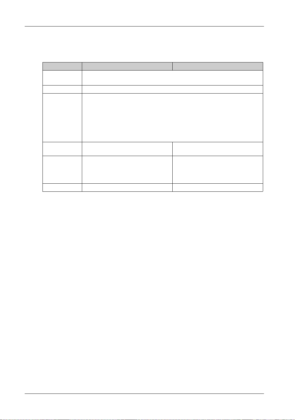
Structural Specifications
FP-5600TPD FP-5700TPD
Grounding
Cooling method Natural air circulation
Structure
External
dimensions
Panel cut
dimensions
Weight 3.9 kg (8.6 lb) or less 5.2 kg (11.5 lb) or less
*1
Functional grounding: Grounding resistance of 100 , 2 mm
or your country’s applicable standard (same for FG and SG terminals).
When using a factory-installed front USB cover: IP65F*, IP67F*, Type 1
When using a front USB cover as an option: IP66F*, IP67F*, Type 1*, Type 4X (Indoor
Use Only)*/13
* On the front panel when properly installed in an enclosure and not using the front panel
USB port.
NOTE: The option is a front USB cover with screw by Pro-face (Model Number
PFXZCDCVUS1).
W315 x H241 x D67 mm
(W12.4 x H9.49 x D2.64 in)
W301.5 x H227.5 mm
(W11.87 x H8.96 in)
Panel thickness area:
1.6...5 mm (0.06...0.2 in)
FP5000 Series User Manual
2
(AWG 14) or thicker wire,
*
*
W397 x H296 x D67 mm
(W15.6 x H11.7 x D2.64 in)
*2
*3
W383.5 x H282.5 mm
(W15.1 x H11.12 in)
Panel thickness area:
1.6...5 mm (0.06...0.2 in)
*2
*3
*1 The front face of this product, installed in a solid panel, has been tested using conditions
equivalent to the standards shown in the specification. Even though this product’s level of
resistance is equivalent to these standards, oils that should have no effect on this product can
possibly harm this product. This can occur in areas where either vaporized oils are present, or
where low viscosity cutting oils are allowed to adhere to this product for long periods of time. If this
product’s front face protection sheet peels off, these conditions can lead to the ingress of oil into
this product and separate protection measures are suggested.
Also, if non-approved oils are present, they may cause deformation or corrosion of the front panel’s
plastic cover. Therefore, prior to installing this product, be sure to confirm the type of conditions
that will be present in this product’s operating environment. If the installation gasket is used for a
long period of time, or if this product and its gasket are removed from the panel, the original level
of protection cannot be kept. To maintain the original protection level, be sure to replace the
installation gasket regularly.
*2 For dimensional tolerance, everything +1/-0 mm (+0.04/-0 in) and R in angle are below R3
(R0.12 in).
*3 Even if the installation wall thickness is within the recommended range for the panel cut
dimensions, depending on wall’s material, size, and installation location of this product and other
devices, the installation wall could warp. To prevent warping, the installation surface may need to
be strengthened.
35
Page 36
Specifications
EQUIPMENT DAMAGE
Ensure the panel is not in permanent and direct contact with oils.
Do not press on the display of this product with excessive force or with a hard object, since it
Failure to follow these instructions can result in injury or equipment damage.
EQUIPMENT DAMAGE
Do not expose the device to direct sunlight.
Failure to follow these instructions can result in injury or equipment damage.
STORAGE AND OPERATION OUTSIDE OF SPECIFICATIONS
Store the panel in areas where temperatures are within the panel’s specifications.
Do not restrict or block the panel’s rear-face ventilation slots.
Failure to follow these instructions can result in equipment damage.
CAUTION
can damage the display. Also, do not press on the touch panel with a pointed object, such as
the tip of a mechanical pencil or a screwdriver. since doing so can damage the touch panel.
CAUTION
NOTICE
NOTICE
GASKET AGING
Inspect the gasket periodically as required by your operating environment to keep the initial IP
level.
Change the gasket at least once a year, or as soon as scratches or dirt become visible.
Failure to follow these instructions can result in equipment damage.
36
Page 37

Functional Specification s
Section 4.2
Functional Specifications
What Is in This Section?
This section contains the following topics:
Display Specifications 38
Touch Panel 39
FP5000 Series User Manual
Topic Page
37
Page 38
Specifications
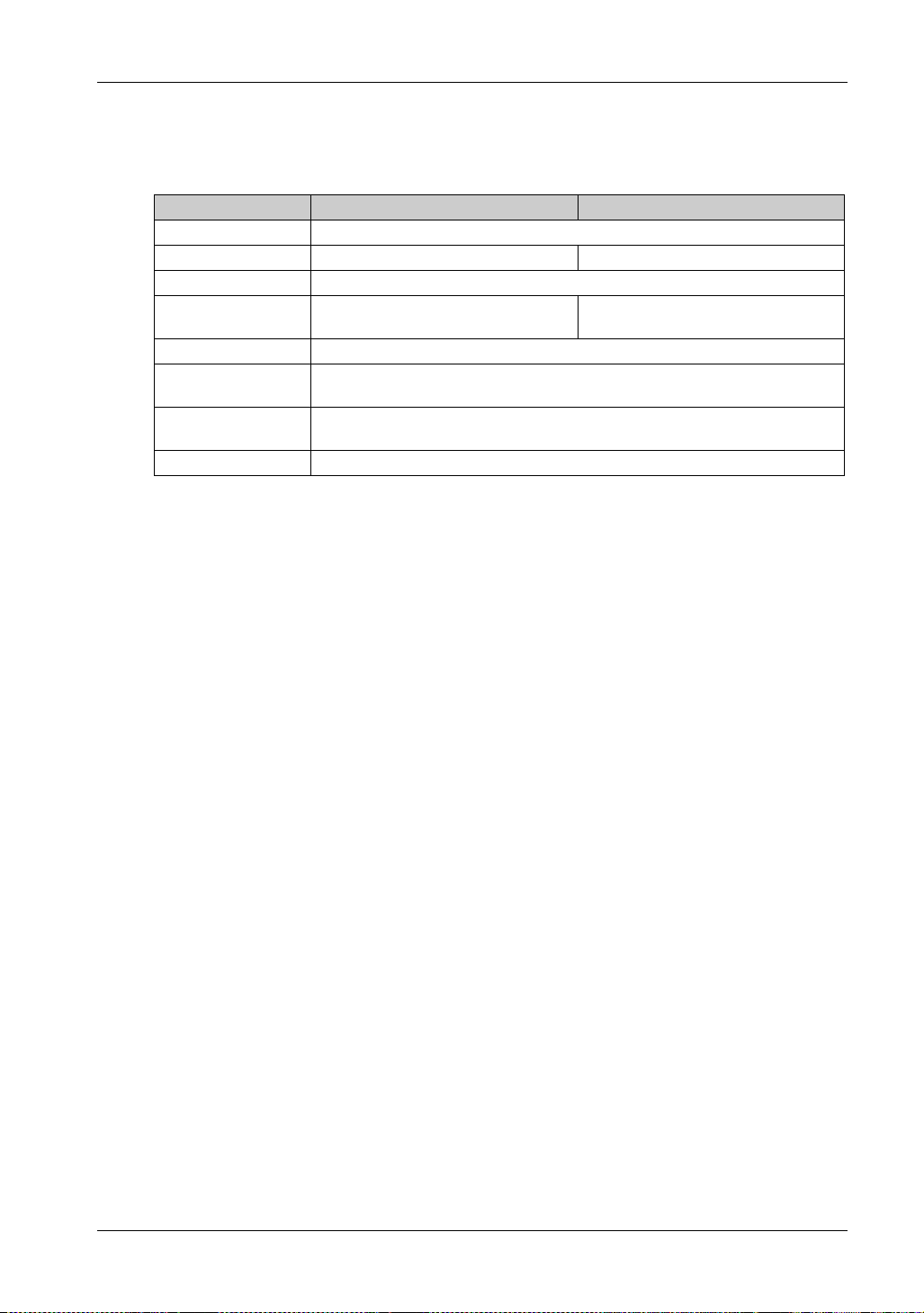
Display Specifications
Display type TFT Color LCD
Display size 12.1-inch 15-inch
Resolution 1,024 x 768 pixels (XGA)
Effective display area W245.76 x H184.32 mm
Display colors 16 million colors
Backlight White LED (Not user replaceable. When replacement is required, contact your local
Backlight service life 50,000 hours or more (continuos operation at 25 C [77 F] before backlight
Brightness control 0...100 (Adjusted with the launcher)
FP-5600TPD FP-5700TPD
W304.1 x H228.1 mm
(W9.68 x H7.26 in)
distributor.)
brightness decreases to 50%)
(W11.97 x H8.98 in)
38
Page 39

Touch Panel
Touch panel type Resistive film (analog, multi-touch)
Touch panel resolution 1,024 x 1,024
Touch panel service life 1 million times or more
FP5000 Series User Manual
39
Page 40

Specifications
Interface Specifications
Section 4.3
Interface Specifications
What Is in This Section?
This section contains the following topics:
Interface Specifications 41
Interface Connection 42
DVI-D Input Interface 45
Topic Page
40
Page 41
Interface Specifications
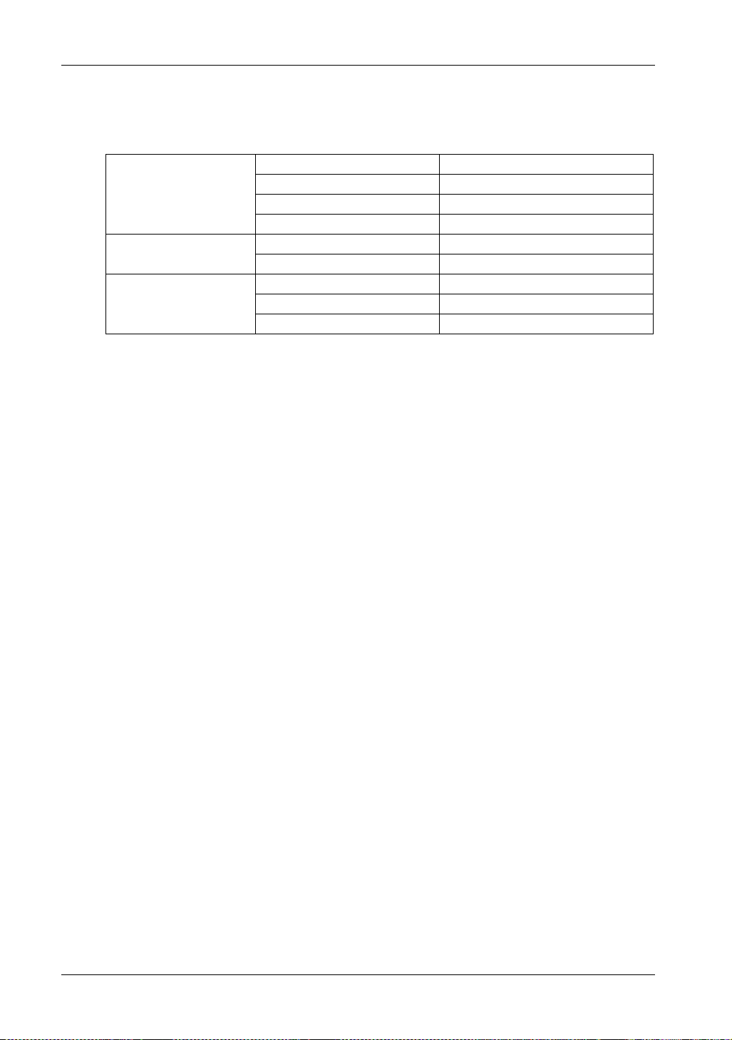
USB (Type A) interface Connector USB 2.0 (Type A) x 1
USB (Type B) interface Connector USB 2.0 (Type B) x 1
Video interface DVI-D DVI-D input
FP5000 Series User Manual
Power supply voltage 5 Vdc ±5%
Maximum supply current 500 mA
Maximum transmission distance 5 m (16.4 ft)
Maximum transmission distance 5 m (16.4 ft)
Connector DVI-D 24 pin (socket) x 1
Maximum transmission distance 5 m (16.4 ft)
41
Page 42

Specifications
Interface Connection
Cable Connections
POTENTIAL FOR EXPLOSION
Always confirm the ANSI/ISA 12.12.01 or CSA C22.2 N213 hazardous location rating of your
device before installing or using it in a hazardous location.
To apply or remove the supply power from this product installed in a Class I, Division 2
hazardous location, you must either:
Use a switch located outside the hazardous environment, or;
Use a switch certified for Class I, Division 1 operation inside the hazardous area.
Do not connect or disconnect equipment unless power has been switched off or the area is
known to be non-hazardous. This applies to all connections including power, ground, serial,
parallel, and network connections.
Never use unshielded / ungrounded cables in hazardous locations.
Use only non-incendiary USB devices.
When enclosed, keep enclosure doors and openings closed at all times to avoid the
accumulation of foreign matter inside the workstation.
Failure to follow these instructions will result in death or serious injury.
DANGER
Division 2 hazardous location regulations require that all cable connections be provided with
adequate strain relief and positive interlock. Use only non-incendive USB devices as USB
connections do not provide adequate strain relief to allow the use of the USB connections of this
product (see page 42). Never connect or disconnect a cable while power is applied at either end
of the cable. All communication cables should include a chassis ground shield. This shield should
include both copper braid and aluminum foil. The D-sub style connector housing must be a metal
conductive type (for example, molded zinc) and the ground shield braid must be terminated directly
to the connector housing. Do not use a shield drain wire.
The outer diameter of the cable must be suited to the inner diameter of the cable connector strain
relief so that a reliable degree of strain relief is maintained. Always secure the D-sub connectors
to the workstation-mating connectors via the two screws located on both sides.
USB Connection
Non-incendive field wiring apparatus (keyboards, mouse) are permitted for use on the front USB
port (Type A) of associated field wiring non-incendive apparatus (this product).
In addition to being non-incendive, any equipment connected to the front USB ports must satisfy
the following criteria.
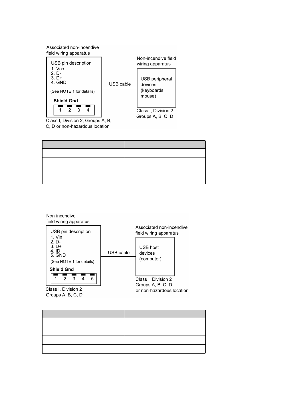
The following figure shows the USB cable wiring:
42
Page 43
<Type A>
Circuit parameters Front USB (Type A)
Open-circuit voltage = V
Short-circuit current = I
oc
sc
Associated capacitance = C
Associated inductance = L
a
a
5.25 V
1300 mA
265 F
16 H
FP5000 Series User Manual
<mini B>
NOTE: The front USB port (mini-B) cannot be used.
Circuit parameters Front USB (mini-B)
Maximum input voltage = V
Maximum load current = I
Internal capacitance = C
Internal inductance = L
i
i
max
max
5.25 V
0.1 mA
0.24 F
16 H
43
Page 44
Specifications
NOTE:
1. The above table lists the non-incendive circuit parameters. The Entity Concept allows interconnection of non-incendive apparatus with associated apparatus – not specifically examined
combinations – as a system when the approved values of V
associated apparatus are less than or equal to V
apparatus, and the approved values of Ca (Co) and La (Lo) for the associated apparatus are greater
than or equal to C
apparatus.
2. Associated non-incendive field wiring apparatus and non-incendive field wiring apparatus shall
satisfy the following:
+ C
i
cable
and Li + L
(or Uo) and Isc (or Io) for the
oc
(Ui) and I
max
, respectively, for the non-incendive field wiring
cable
(Ii) for the non-incendive
max
Associated non-incendive
field wiring apparatus
V
oc
I
sc
C
a
L
a
- Non-incendive field wiring
apparatus
V
I
Ci + C
Li + L
max
max
cable
cable
3. If the electrical parameters of the cable are unknown, the following values may be used:
= 196.85 pF/m (60 pF/ft)
C
cable
=0.656H/m (0.20 H/ft)
L
cable
4. Wiring methods must be in accordance with the electrical code of the country where it is used.
This product must be installed in an enclosure. If installed in a Class I, Division 2 Location, the
enclosure must be capable of accepting one or more Division 2 wiring methods.
DANGER
POTENTIAL FOR EXPLOSION
Verify the power, input, and output (I/O) wiring are in accordance with Class I, Division 2 wiring
methods.
Substitution of any components may impair suitability for Class I, Division 2.
Do not disconnect equipment while the circuit is live or unless the area is known to be free of
ignitable concentrations.
Remove power before attaching or detaching any connectors to or from this product.
Ensure that power, communication, and accessory connections do not place excessive stress
on the ports. Consider the vibration in the environment when making this determination.
Securely attach power, communication, and external accessory cables to the panel or cabinet.
Use either a USB cable by Pro-face or a commercial-type USB cable.
Use only non-incendive USB configurations.
The associated non-incendive field wiring apparatus shall not be connected in parallel unless
approved by the associated non-incendive apparatus.
This product is suitable for use and provides non-incendive field wiring to apparatus in Class
I, Division 2, Groups A, B, C, D.
Failure to follow these instructions will result in death or serious injury.
44
Page 45
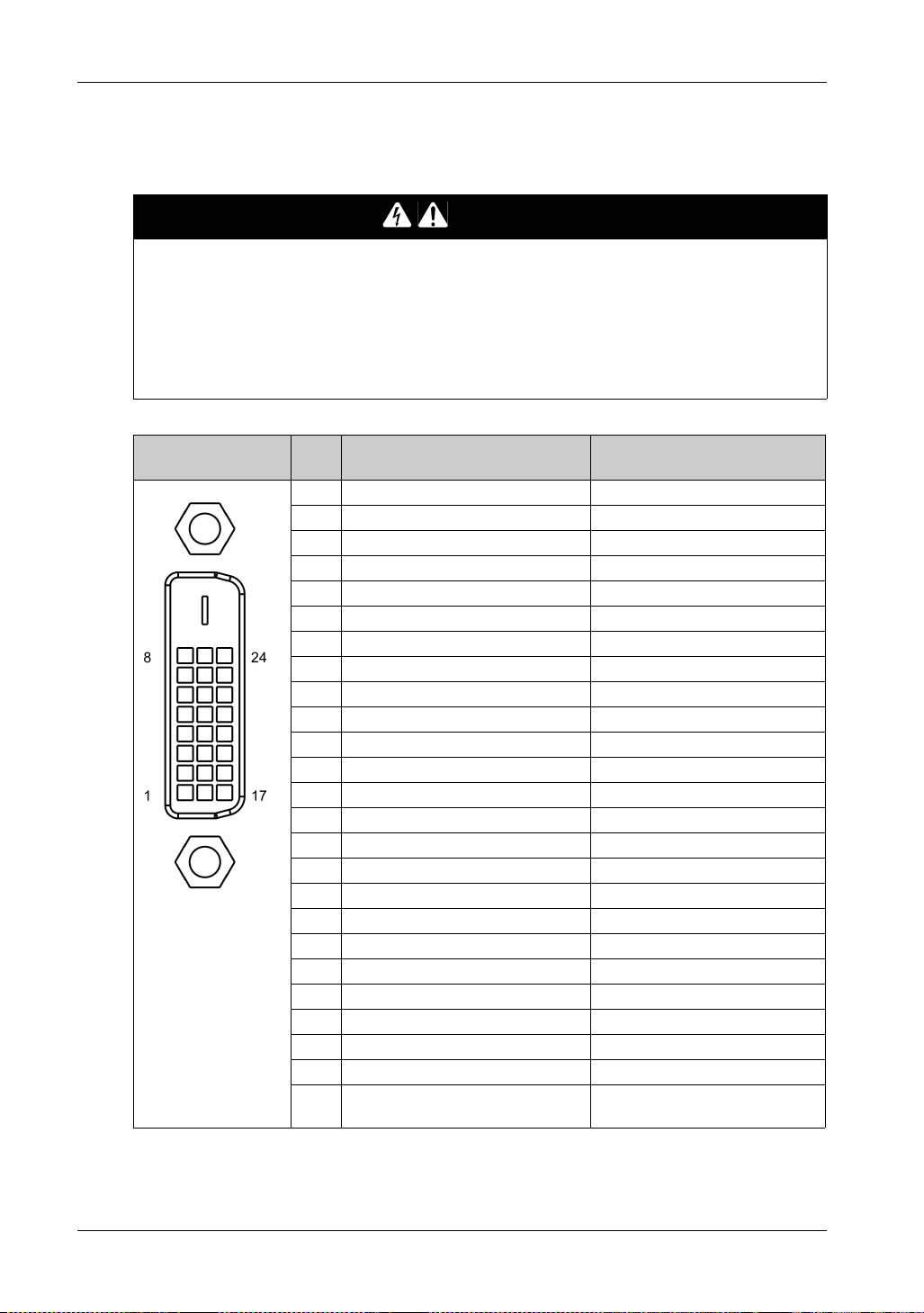
DVI-D Input Interface
ELECTRIC SHOCK AND FIRE
When using the SG terminal to connect an external device to this product:
Verify that a short-circuit loop is not created when you set up the system.
Connect the SG terminal to remote equipment when the external device is not isolated.
Connect the SG terminal to a known reliable ground connection to reduce the risk of damaging
the circuit.
Failure to follow these instructions will result in death or serious injury.
FP5000 Series User Manual
DANGER
Product side Pin
No.
1 TMDS DATA 2- Input
2 TMDS DATA 2+ Input
3 TMDS DATA 2 SHIELD (SG) –
4NC –
5NC –
6 DDC Clock Input
7 DDC Data Input/Output
8NC –
9 TMDS DATA 1- Input
10 TMDS DATA 1+ Input
11 TMDS DATA 1 SHIELD (SG) –
12 NC –
13 NC –
14 NC –
15 SHIELD (SG) –
16 Hot Plug Detect Output
17 TMDS DATA 0- Input
18 TMDS DATA 0+ Input
19 TMDS DATA 0 SHIELD (SG) –
20 NC –
21 NC –
22 TMDS CLOCK SHIELD (SG) –
23 TMDS CLOCK+ Input
24 TMDS CLOCK- Input
Shell FG Functional Ground (Common with
Signal name Direction
SG)
45
Page 46
Specifications
Recommendations:
DVI-D cable by Pro-face (FP-DV01-50 <5 m>)
NOTE:
For noise-free operation, use the recommended DVI-D cable.
When you use a commercial-type cable, the maximum length is 5 m.
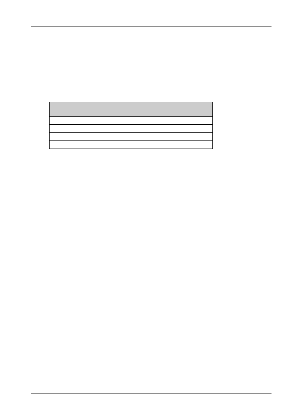
Display Resolution
Resolution H. sync.
(kHz)
640 x 480 31.469 59.940 25.175
800 x 600 37.879 60.317 40.000
1024 x 768 48.363 60.004 65.000
1280 x 1024 63.981 60.000 108.000
V. sync.
(Hz)
Dot clock
(MHz)
46
Page 47
FP5000 Series User Manual
Dimensions
iDisplay_PF 12/2017
Dimensions
Chapter 5
Dimensions
Introduction
This chapter presents the product external dimensions.
What Is in This Chapter?
This chapter contains the following topics:
FP-5600TPD 48
FP-5700TPD 50
FP5000 Series User Manual
Topic Page
47
Page 48
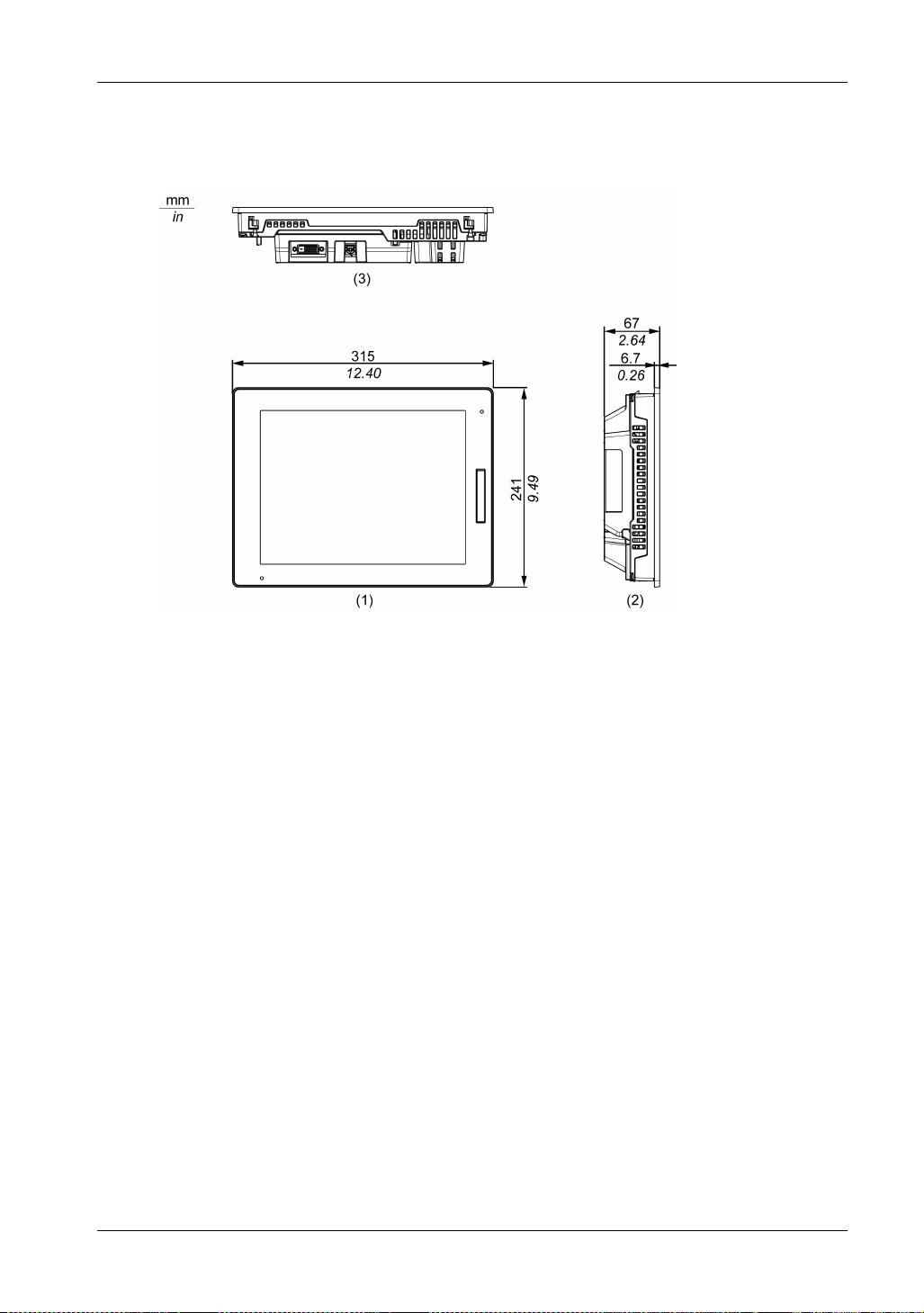
Dimensions
FP-5600TPD
External Dimensions
1 Front
2 Left
3 Bottom
48
Page 49
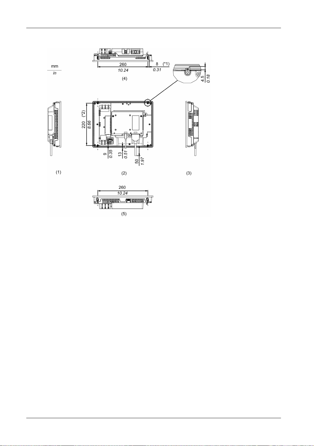
Dimensions with Cables
FP5000 Series User Manual
*1 Rotation area of the fastener
*2 Pitch of the center of installation fastener screws
1 Right
2 Rear
3 Left
4 Bottom
5 Top
NOTE: All the above values are designed with cable bending in mind. The dimensions given here
are representative values depending on the type of connection cable in use. Therefore, these
values are intended for reference only.
49
Page 50
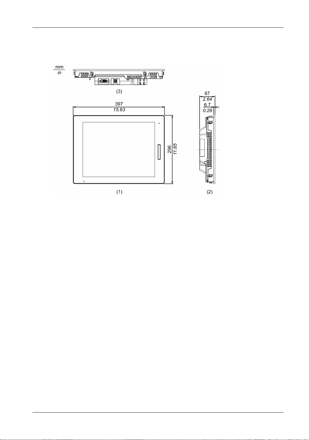
Dimensions
FP-5700TPD
External Dimensions
1 Front
2 Left
3 Bottom
50
Page 51
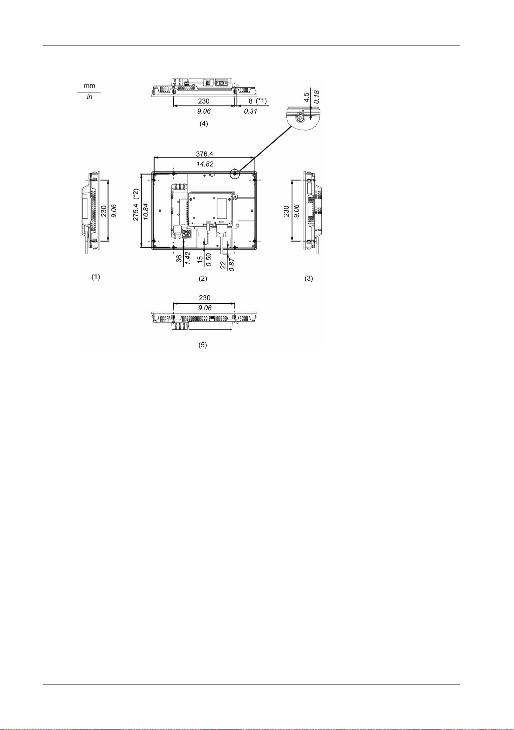
Dimensions with Cables
FP5000 Series User Manual
*1 Rotation area of the fastener
*2 Pitch of the center of installation fastener screws
1 Right
2 Rear
3 Left
4 Bottom
5 Top
NOTE: All the above values are designed with cable bending in mind. The dimensions given here
are representative values depending on the type of connection cable in use. Therefore, these
values are intended for reference only.
51
Page 52

Dimensions
52
Page 53
FP5000 Series User Manual
Installation and Wiring
iDisplay_PF 12/2017
Installation and Wiring
Chapter 6
Installation and Wiring
Introduction
This chapter describes the installation procedures and wiring principles for this product and
peripheral devices.
What Is in This Chapter?
This chapter contains the following sections:
Section Topic Page
6.1 Installation 54
6.2 Wiring Principles 61
6.3 USB Cable Clamp 67
6.4 Front USB Cover 70
FP5000 Series User Manual
53
Page 54
Installation and Wiring
Installation
Section 6.1
Installation
Installation Procedures
Introduction
This product is designed for use on a flat surface of Type 1, Type 4X (Indoor Use Only) or Type 13
Enclosure.
Mount this product in an enclosure that provides a clean, dry, robust and controlled environment
*1
(IP65F
When using a factory-installed front USB cover (without screw), the front surface is IP65F
IP67F
Number PFXZCDCVUS1), the front surface is IP66F
Only) or Type 13 Enclosure.
Display front surface Enclosure front surface
Without screw With screw
IP65F, IP67F, Type 1 IP66F, IP67F, Type 1, Type 4X
, IP66F*1, IP67F*1, Type 1, Type 4X [Indoor Use Only], or Type 13 Enclosure).
*1
or Type 1 Enclosure. When using a front USB cover (with screw*2) by Pro-face (Model
(Indoor Use Only), Type 13
*1
, IP67F*1, Type 1, Type 4X (Indoor Use
IP65F, IP66F, IP67F, Type 1,
Type 4X (Indoor Use Only),
Type 13
*1
,
Regardless of using a factory-installed front USB cover or a front USB cover with screw, when the
cover is open, the front surface is Type 1 Enclosure.
Be aware of the following when building this product into an end-use product:
The rear face of this product is not approved as an enclosure. When building this product into
an end-use product, be sure to use an enclosure that satisfies standards as the end-use
product’s overall enclosure.
This product must be used indoors only.
Install and operate this product with its front panel facing outward.
*1 IP65F, IP66F and IP67F are not part of the UL certification.
*2 The necessary torque is 0.5 N•m (4.4 lb-in).
Installation Requirements
Check that the installation wall or cabinet surface is flat, in good condition and has no jagged
edges. Metal reinforcing strips may be attached to the inside of the wall, near the panel-cut,
to increase its rigidity.
Decide on the thickness of the enclosure wall, based on the level of strength required:
1.6...5 mm (0.06...0.2 in).
Even if the installation wall thickness is within the recommended range for the panel cut
dimensions, depending on wall’s material, size, and installation location of this product and
other devices, the installation wall could warp. To prevent warping, the installation surface
may need to be strengthened.
54
Page 55
FP5000 Series User Manual
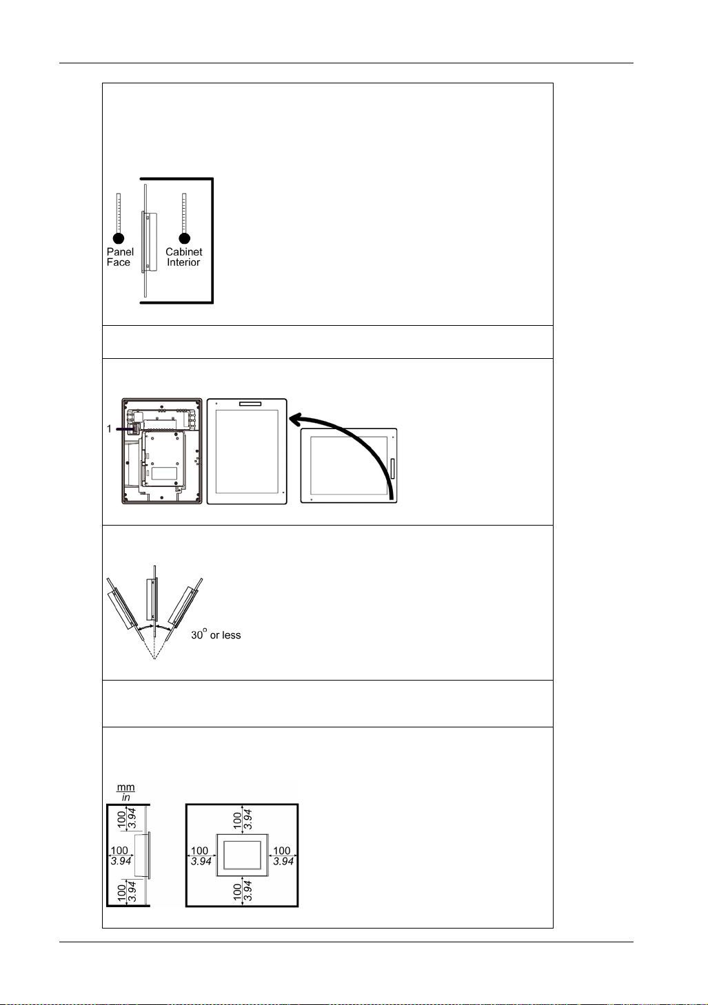
Be sure that the surrounding air temperature and the ambient humidity are within their
designated ranges. Surrounding air temperature: 0 to 60 C (32 to 140 F) (see the
Environment Specifications for this product); ambient humidity: 10 to 90% RH; wet bulb
temperature: maximum 39 C (102 F). When installing this product in a cabinet or
enclosure, the surrounding air temperature is the cabinet’s or enclosure’s internal
temperature.
Be sure that heat from surrounding equipment does not cause this product to exceed its
standard operating temperature.
When mounting this product vertically, ensure that the right side of this product faces up. In
other words, the DC power connector should be at the top.
1 Power connector
When installing this product in a slanted position, the product face should not incline more
than 30
When installing this product in a slanted position with an incline more than 30, the ambient
temperature must not exceed 40 C (104 F). You may need to use forced air cooling (fan,
A/C) to ensure the ambient operating temperature is 40 C or less (104 F or less).
For easier maintenance, operation and improved ventilation, install this product at least
100 mm (3.94 in) away from adjacent structures and other equipment as shown in the
following illustration:
55
Page 56
Installation and Wiring
You can attach a commercial-type arm or wall-mount adapter using the arm mounting holes
(VESA 75 mm specification) at the back of this product. Attach the four (4) M4 attachment
screws (screw length: 10 mm [0.4 in]). The torque required for these screws is 0.7 to 0.8 N•m
(6.2 to 7.1 lb-in).
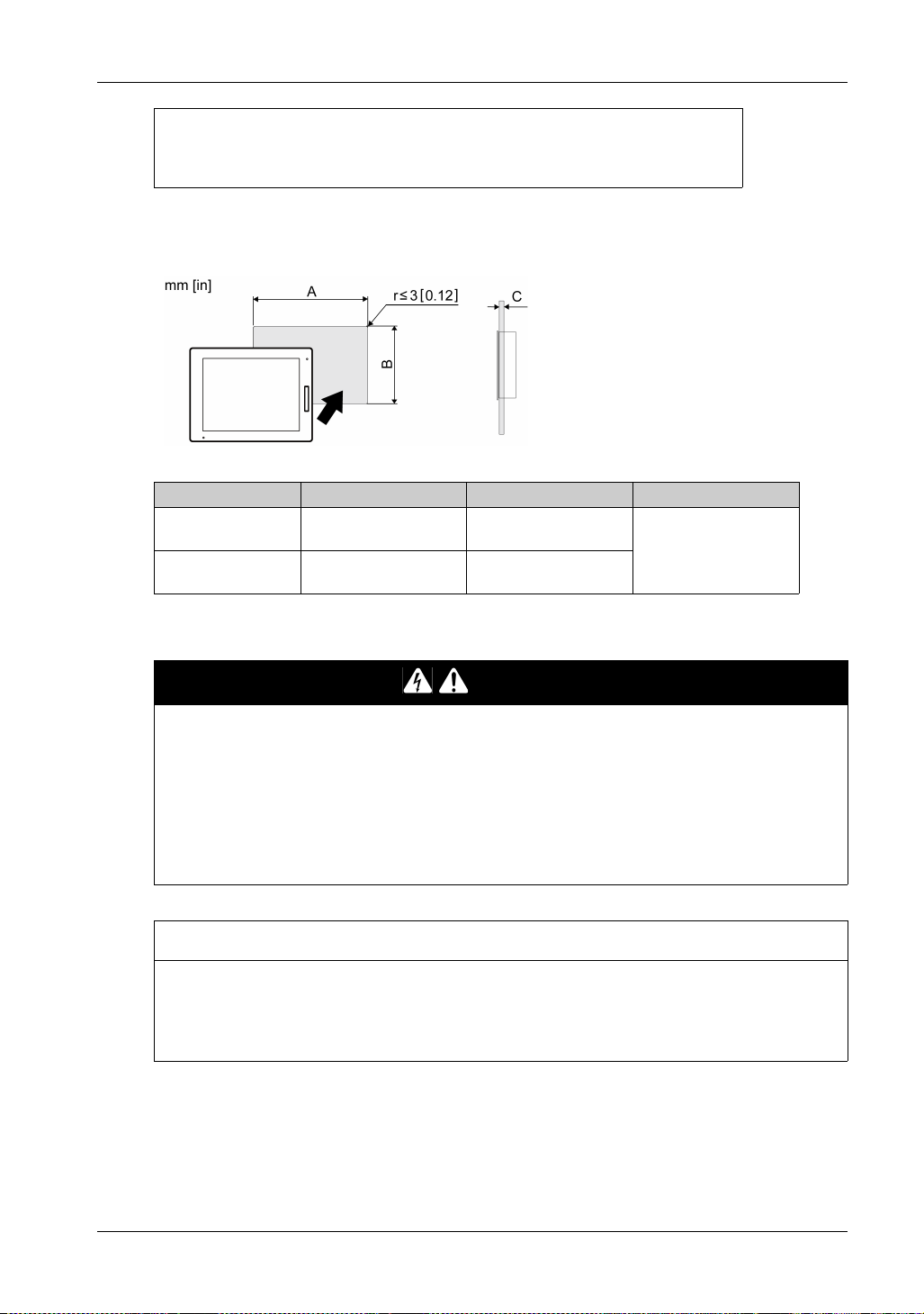
Panel Cut Dimensions
Based on the panel cut dimensions, open a mount hole on the panel.
Display size A B C
12.1-inch models 301.5 mm (+1/-0 mm)
15-inch models 383.5 mm (+1/-0 mm)
(11.87 in [+0.04/-0 in])
(15.1 in [+0.04/-0 in])
227.5 mm (+1/-0 mm)
(8.96 in [+0.04/-0 in])
282.5 mm (+1/-0 mm)
(11.12 in [+0.04/-0 in])
1.6...5 mm
(0.06...0.2 in)
Installing to the Panel
HAZARD OF ELECTRIC SHOCK, EXPLOSION, OR ARC FLASH
Remove all power from the device before removing any covers or elements of the system, and
prior to installing or removing any accessories, hardware, or cables.
Unplug the power cable from both this product and the power supply.
Always use a properly rated voltage sensing device to confirm power is off.
Replace and secure all covers or elements of the system before applying power to this
product.
Failure to follow these instructions will result in death or serious injury.
EQUIPMENT DAMAGE
Keep this product stabilized in the panel-cut while you are installing or removing the screw
fasteners.
Failure to follow these instructions can result in equipment damage.
DANGER
NOTICE
56
Page 57
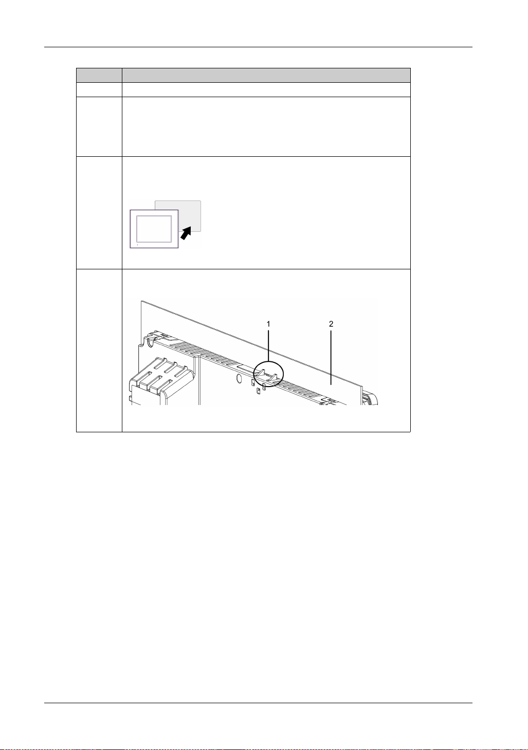
Step Action
1 Place this product on a clean and level surface with the screen facing down.
2 Check that the gasket of this product is seated securely into the gasket’s
groove, which runs around the perimeter of the display panel frame.
NOTE: Always use the installation gasket, since it absorbs vibration in addition
to repelling water. For the procedure on replacing the installation gasket, refer
to Replacing the Installation Gasket (see page 92).
3 Based on the panel cut dimensions of this product (see page 56), open a
mount-hole on the panel and attach this product to the panel from the front
side.
4 Confirm that the anti-drop lock on the top of this product is attached to the
panel.
FP5000 Series User Manual
1 Anti-drop lock
2 Panel
57
Page 58
Installation and Wiring
Step Action
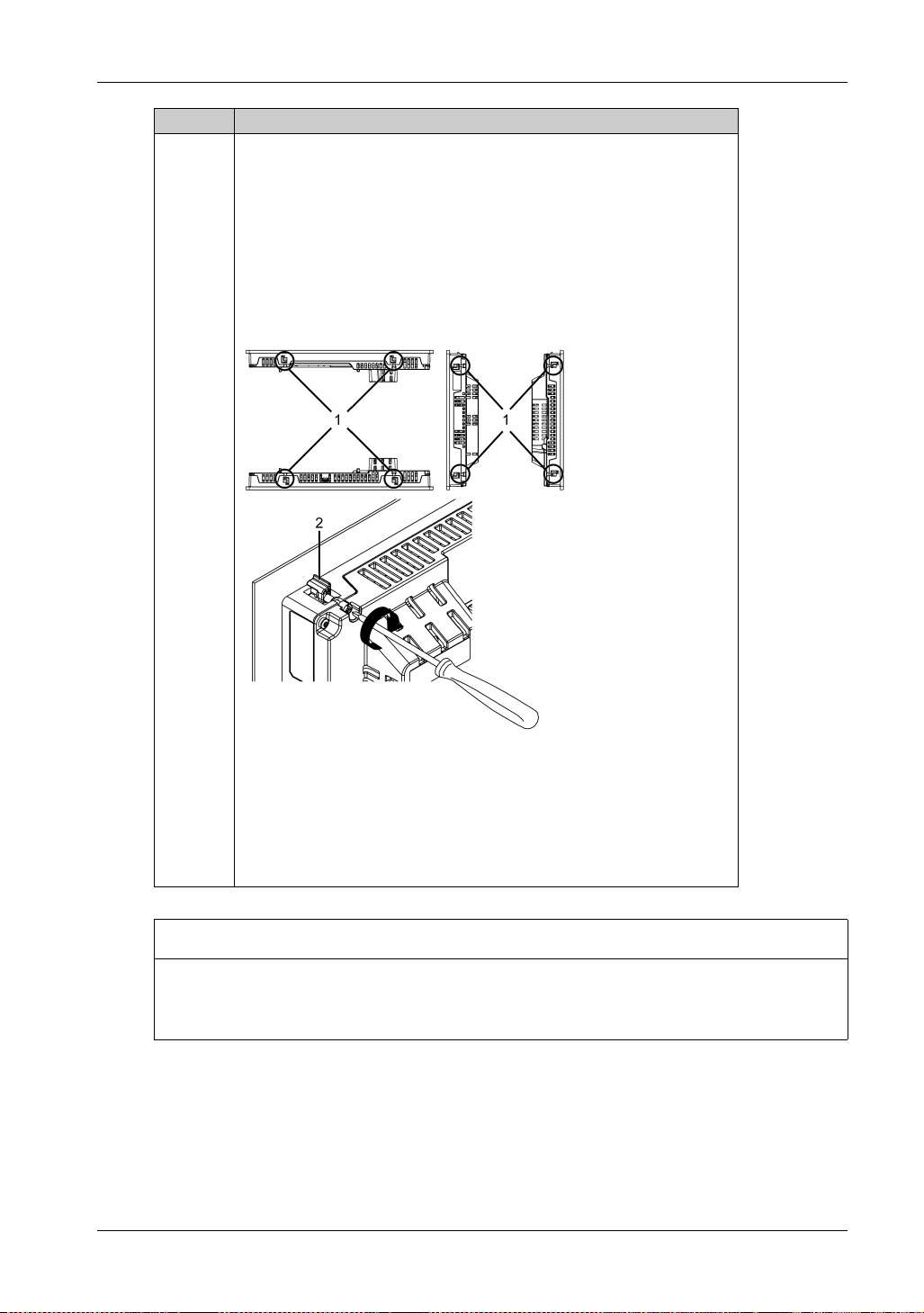
5 Using a Phillips screwdriver, gradually tighten (turn clockwise) the screws for
the fasteners (top, bottom, left, and right), alternating diagonally between
screws until all are secure. Be sure that the L-shaped part of the installation
fastener (2 in figure below) is completely vertical. The necessary torque is
0.5 N•m (4.4 lb-in).
NOTE:
If this product is not mounted properly, it may fall.
If the panel is thick (approx. 5 mm [0.2 in]), you may have trouble
straightening the L-shaped part of the installation fastener. If this happens,
push this product from the front as you tighten the screws.
58
1 Installation fastener
2 L-shaped part of the installation fastener
Number of Installation Fasteners
15-inch models:
Top - 2, Bottom - 2, Right - 2, Left - 2
12-inch models:
Top - 2, Bottom - 2, Right - none, Left - none
NOTICE
BROKEN ENCLOSURE
Do not exert more than 0.5 N•m (4.4 lb-in) of torque when tightening the fastener’s screws.
Failure to follow these instructions can result in equipment damage.
Page 59
Removing from the Panel
HAZARD OF ELECTRIC SHOCK, EXPLOSION, OR ARC FLASH
Remove all power from the device before removing any covers or elements of the system, and
prior to installing or removing any accessories, hardware, or cables.
Unplug the power cable from both this product and the power supply.
Always use a properly rated voltage sensing device to confirm power is off.
Replace and secure all covers or elements of the system before applying power to this
product.
Failure to follow these instructions will result in death or serious injury.
EQUIPMENT DAMAGE
Keep this product stabilized in the panel-cut while you are installing or removing the screw
fasteners.
To avoid damage, remove this product while pushing the anti-drop lock or by making sure the
lock does not touch the panel.
Failure to follow these instructions can result in equipment damage.
FP5000 Series User Manual
DANGER
NOTICE
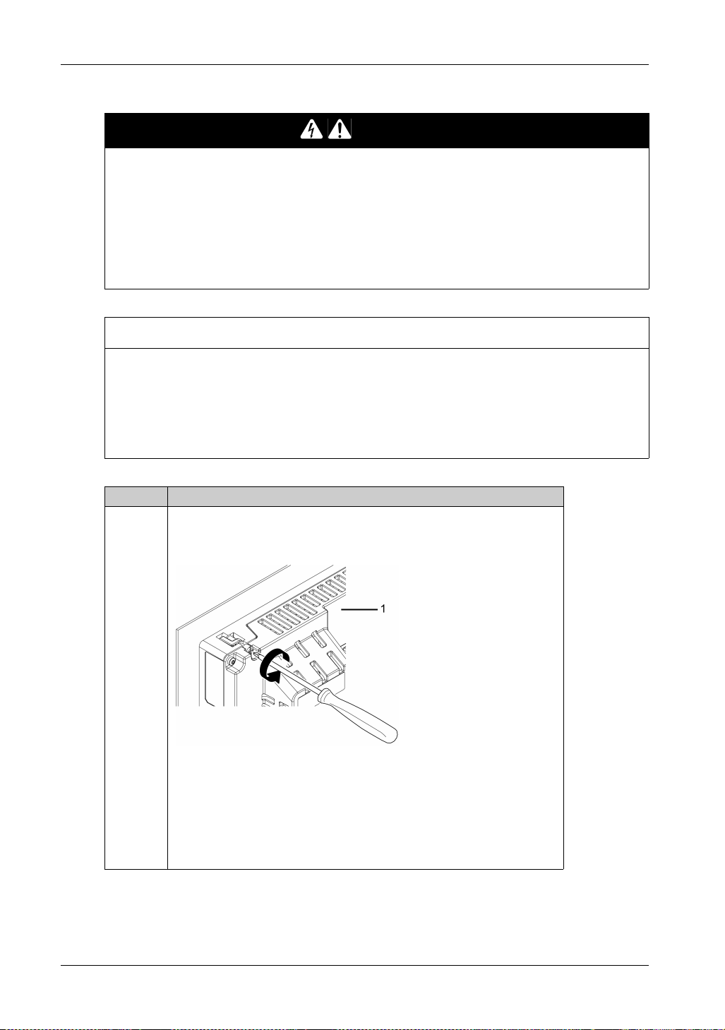
Step Action
1 Using a Phillips screwdriver, gradually loosen (turn counterclockwise) the
screws for the fasteners (top, bottom, left, and right), alternating diagonally
between screws until all screws are loose.
1 Rear side
NOTE:
For the number of installation fasteners on your model, see Number of
Installation Fasteners in Step 5 of Installing to the Panel (see page 56)
If the panel is thick (approx. 5 mm [0.2 in]), you may have trouble
straightening the L-shaped part of the installation fastener. If this happens,
push this product from the front as you loosen the screws.
59
Page 60
Installation and Wiring
Step Action
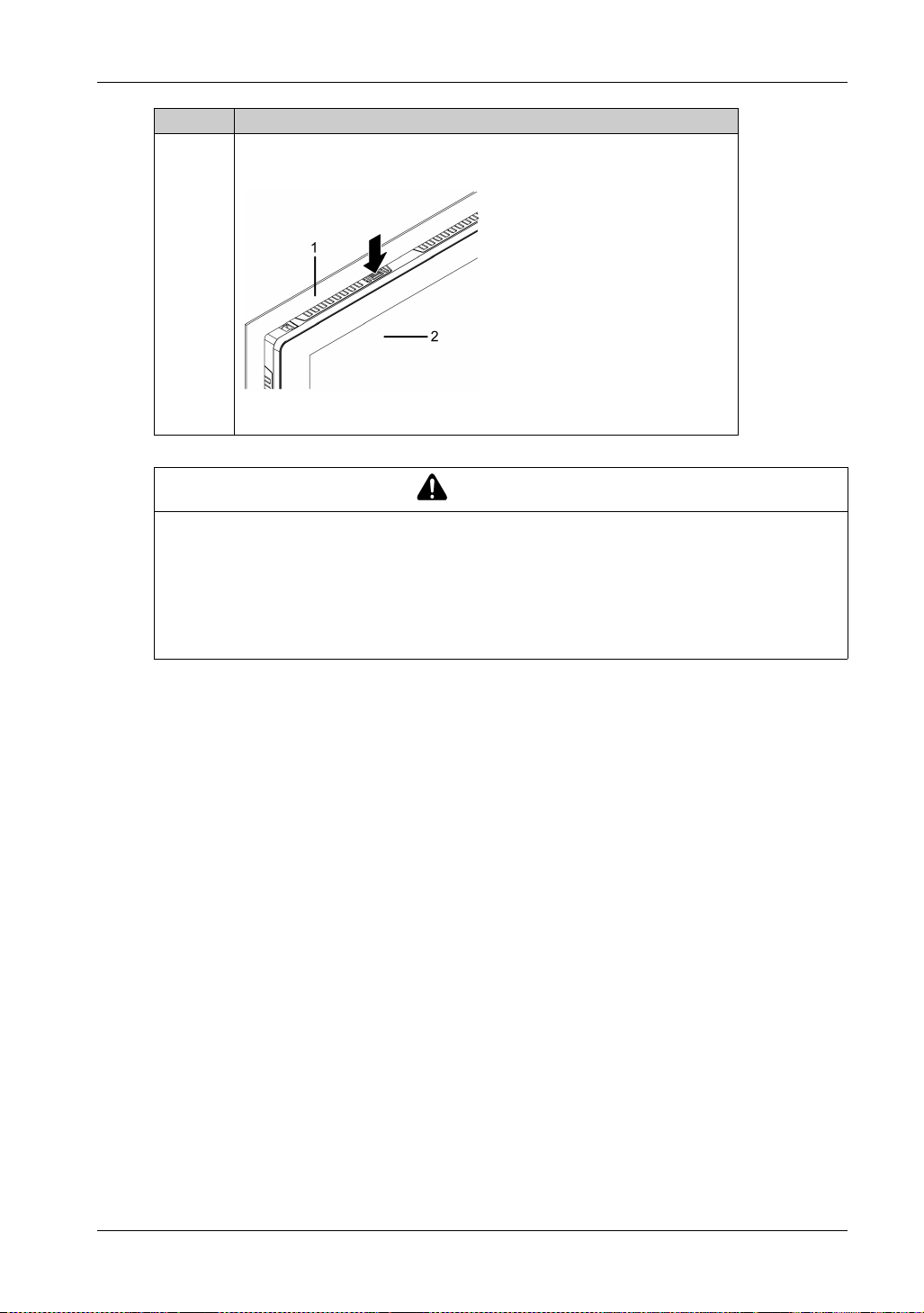
2 While pushing on the anti-drop lock on the top of this product with a tool such
RISK OF INJURY
Do not drop this product when you remove it from the panel.
Hold this product in place after removing the fasteners.
Use both hands.
While pushing on the anti-drop lock, be careful not to hurt your fingers.
Failure to follow these instructions can result in injury or equipment damage.
as a screwdriver, slowly remove this product from the panel.
1 Panel
2 Front side
CAUTION
60
Page 61

Wiring Principles
Section 6.2
Wiring Principles
What Is in This Section?
This section contains the following topics:
Connecting the DC Power Cord 62
Connecting the Power Supply 64
Grounding 66
FP5000 Series User Manual
Topic Page
61
Page 62
Installation and Wiring
Connecting the DC Power Cord
HAZARD OF ELECTRIC SHOCK, EXPLOSION, OR ARC FLASH
Remove all power from the device before removing any covers or elements of the system, and
prior to installing or removing any accessories, hardware, or cables.
Remove power before wiring this product’s power terminals.
Always use a properly rated voltage sensing device to confirm power is off.
Replace and secure all covers or elements of the system before applying power to this
product.
This product uses only 12...24 Vdc power. Using any other level of power can damage both
the power supply and this product.
Since this product is not equipped with a power switch, be sure to connect a power switch to
the power supply.
Be sure to ground this product’s FG terminal.
Failure to follow these instructions will result in death or serious injury.
NOTE:
The SG (signal ground) and FG (functional ground) terminals are connected internally in this
product.
When the FG terminal is connected, be sure the wire is grounded. Not grounding this product
can result in excessive electromagentic interference (EMI).
DANGER
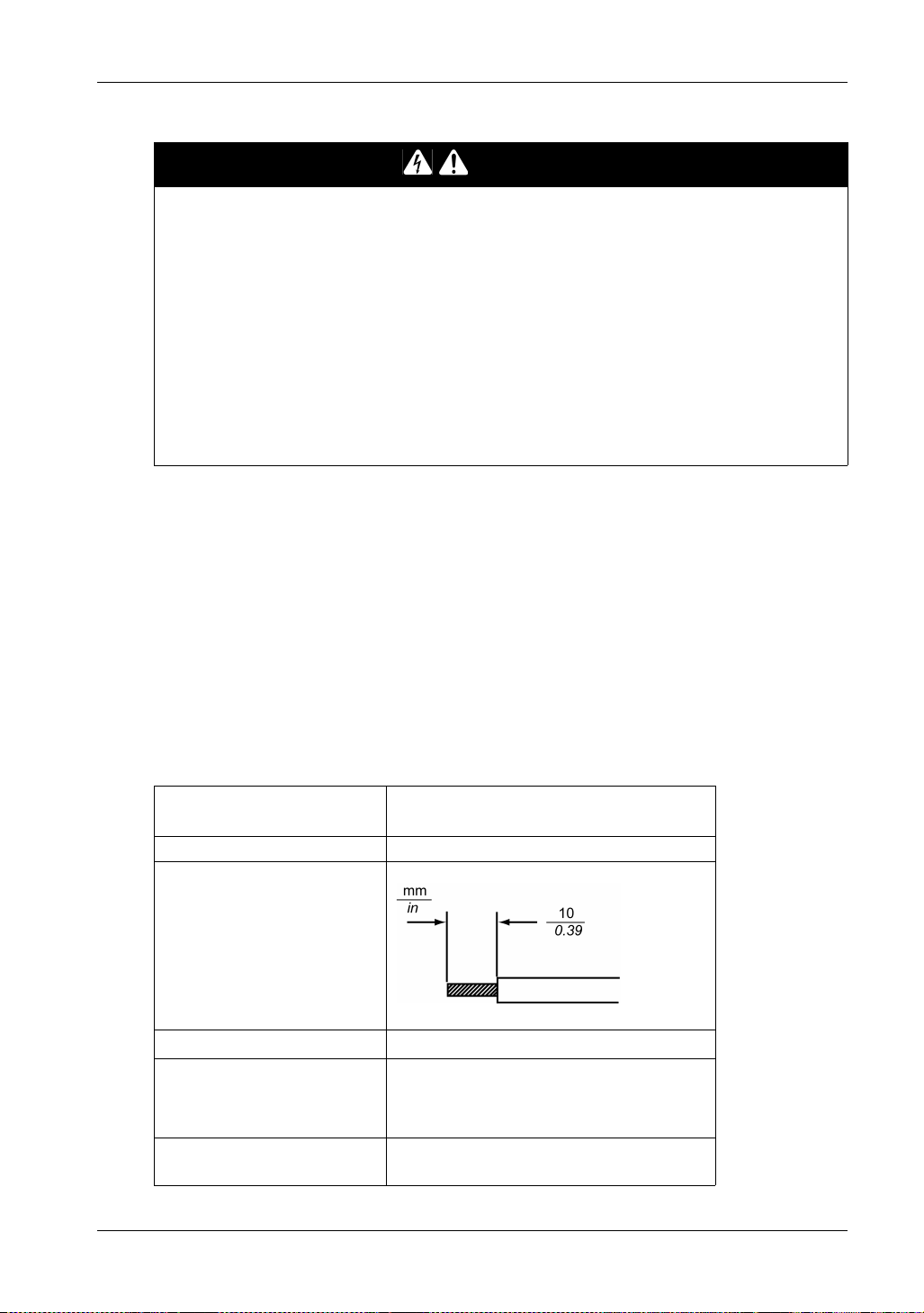
DC Power Cord Preparation
Make sure the ground wire is either the same or heavier gauge than the power wires.
Do not use aluminum wires in the power supply cord.
To prevent the possibility of a terminal short, use a pin terminal that has an insulating sleeve.
If the ends of the individual wires are not twisted correctly, the wires may create a short circuit.
The conductor type is solid or stranded wire.
Use copper wire rated for 75 C (167 F) or higher.
Power cord diameter
Conductor type Solid or stranded wire
Conductor length
Recommended driver
*2
Recommended pin terminals
Recommended pin terminal crimp
*2
tool
*1 For UL compatibility, use AWG14 or AWG13.
0.75...2.5 mm
18...13 AWG
SZS 0.6 x 3.5 (1205053)
*2
3201288 AI 0,75 - 10 GY
3200182 AI 1 - 10 RD
3200195 AI 1,5 - 10 BK
3202533 AI 2,5 - 10 BU
CRIMPFOX 6
2
*1
62
Page 63
*2 Items are manufactured by Phoenix Contact.
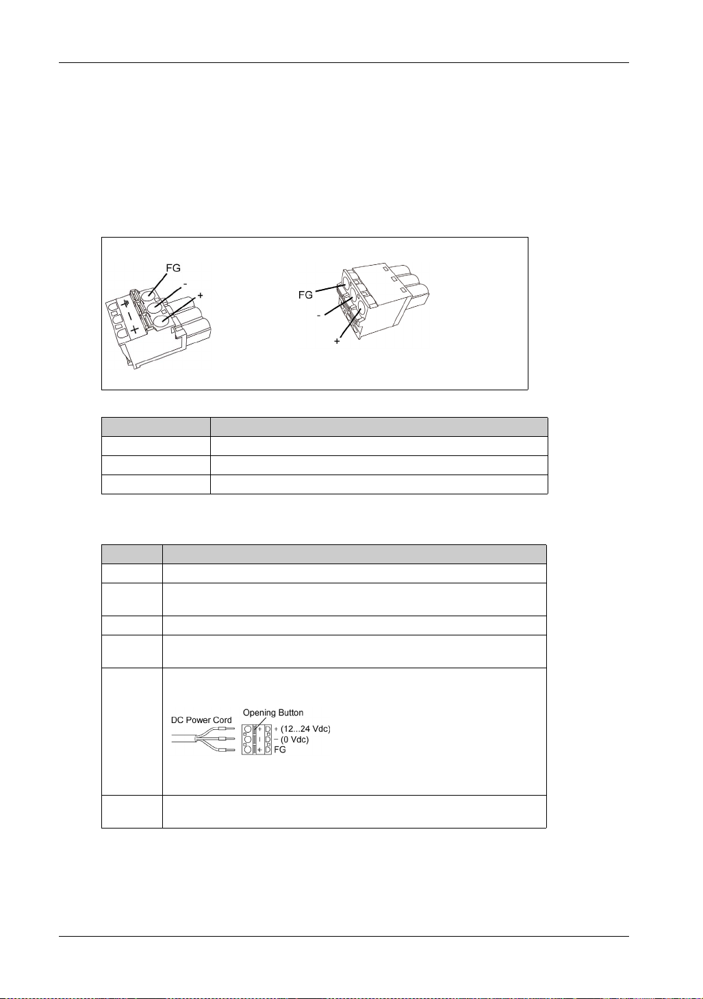
Power Supply Connector Specifications: Spring Clamp Terminal Blocks
This product comes with the right-angle-type power connector.
NOTE:
You can also use a straight-type power connector.
Right-angle type: PFXZCBCNDC2 by Pro-face.
Straight type: PFXZCBCNDC1 by Pro-face.
Right-angle type Straight type
Connection Wire
+ 12...24 Vdc
-0Vdc
FG Grounded terminal connected to the panel chassis.
FP5000 Series User Manual
How to connect the DC Power Cord
Step Action
1 Confirm the power cord is not connected to the power supply.
2 Check the rated voltage and remove the “DC24V” sticker on the DC power
supply connector.
3 Connect each wire from the power cable to a pin terminal.
4 Push the opening button with a small and flat screwdriver to open the desired
pin hole.
5 Insert each power cord wire into its corresponding holder. Release the opening
button to clamp the wire in place.
When using stranded wire, do not short with neighboring wires.
6 After inserting all three power cord wires, insert the DC power supply connector
into the power connector on this product.
NOTE: Do not solder the wire directly to the power crimp pin.
63
Page 64
Installation and Wiring
Connecting the Power Supply
Precautions
Excessive stress on the power connection or attempting to install this product with the power
cables connected may disconnect or cause damage to the power connections. This can cause
short circuits, fire or unintended equipment operation.
SHORT CIRCUIT, FIRE, OR UNINTENDED EQUIPMENT OPERATION
Avoid excessive force on the power cable to prevent accidental disconnection
Securely attach power cables to an installation panel or cabinet.
Use the designated torque to tighten this product’s terminal block screws.
Install and fasten this product on installation panel or cabinet prior to connecting power supply
and communication lines.
Failure to follow these instructions can result in death, serious injury, or equipment
damage.
Improving Noise/Surge
This product’s power supply cord should not be bundled with or kept close to main circuit lines
(high voltage, high current), power lines, or input/output lines, and their various systems should
be kept separate. When power lines cannot be wired via a separate system, use shielded cables
for input/output lines.
Make the power cord as short as possible, and be sure to twist the ends of the wires together
(i.e. twisted pair cabling) from close to the power supply unit.
If there is an excess amount of noise on the power supply line, reduce the noise with a noise
filter before turning on the power.
Connect a lightning surge absorber to handle power surges.
To increase noise resistance, attach a ferrite core to the power cable.
WARNING
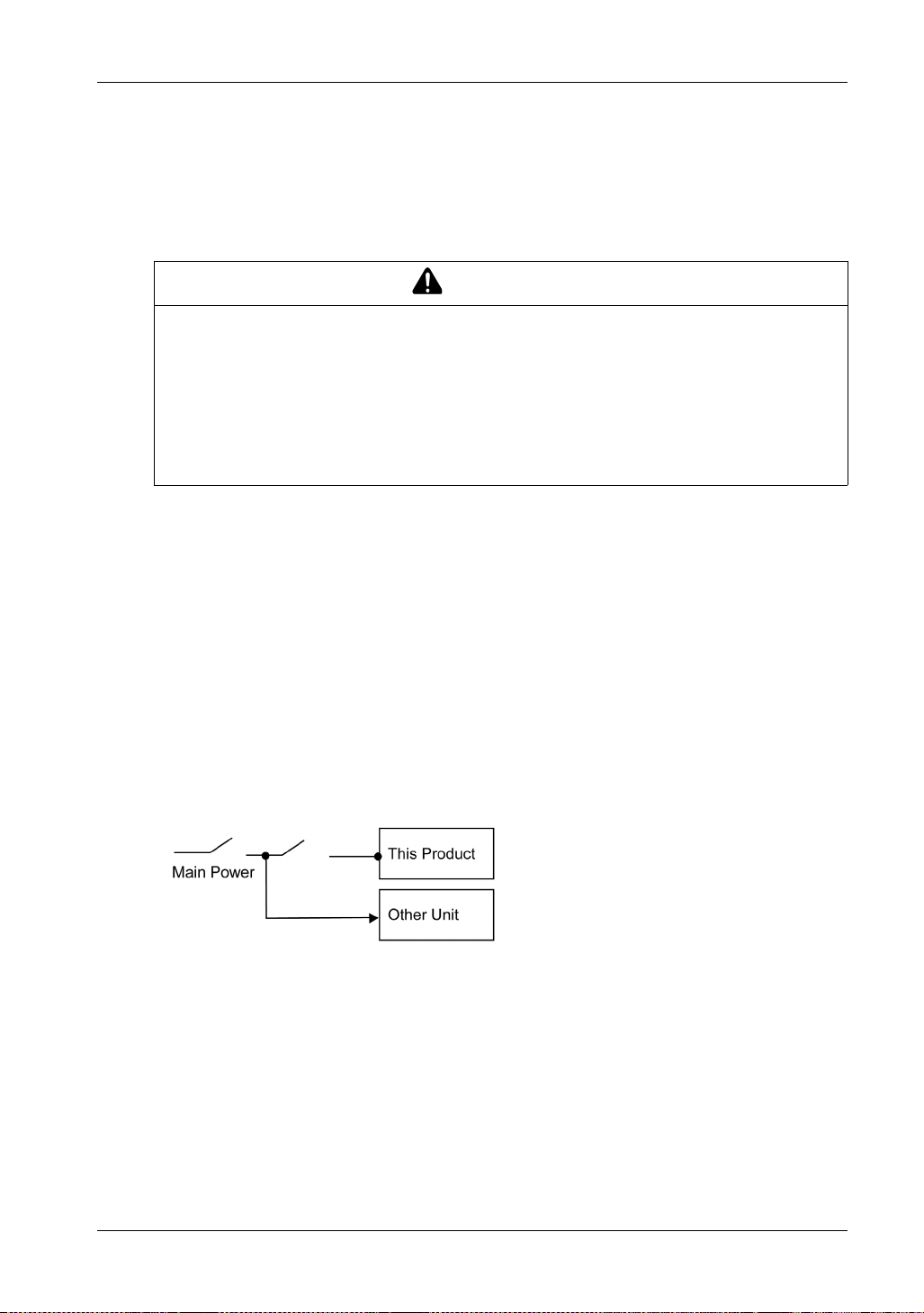
Power Supply Connections
When supplying power to this product, connect the power as shown below.
Branch circuit protective device shall be used for rating 20 A input device for this product.
You must use DC input with an isolating source for this product.
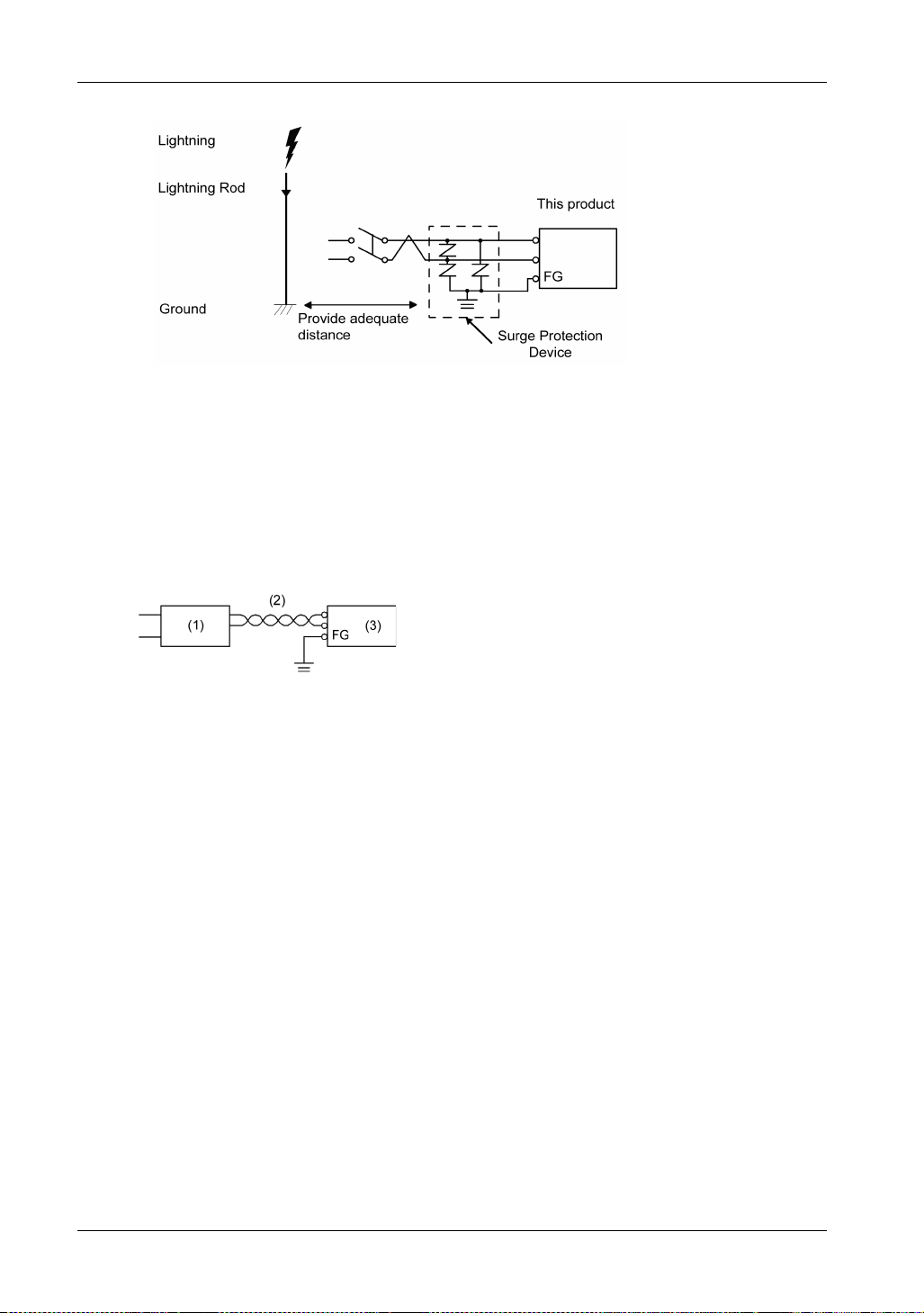
The following shows a surge protection device connection:
64
Page 65
FP5000 Series User Manual
Attach a surge device to prevent damage to this product as a result of a lightning-induced power
surge from a large electromagnetic field generated from a direct lightning strike. We also
strongly recommend to connect the crossover grounding wire of this product to a position close
to the ground terminal of the surge protection device.
It is expected that there will be an effect on this product due to fluctuations in grounding potential
when there is a large surge flow of electrical energy to the lightning rod ground at the time of a
lightning strike. Provide adequate distance between the lightning rod grounding point and the
surge protection device grounding point.
If the voltage variation is outside the prescribed range, connect a regulated power supply.
1 Regulated power supply
2 Twisted-pair cord
3 This product
65
Page 66
Installation and Wiring
Grounding
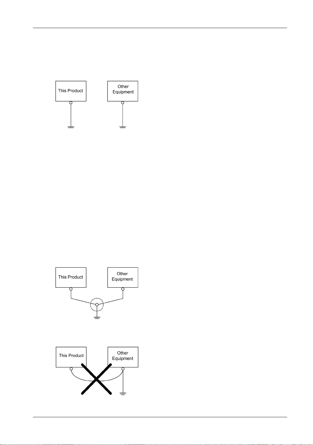
Exclusive Grounding
Always ground the FG (functional ground) terminal. Be sure to separate this product from the FG
of other devices as shown below.
Precautions
Check that the grounding resistance is 100 or less
The FG wire should have a cross sectional area greater than 2 mm
connection point as close to this product as possible, and make the wire as short as possible.
When using a long grounding wire, replace the thin wire with a thicker wire, and place it in a duct.
The SG (signal ground) and FG (functional ground) terminals are connected internally in this
product. When connecting the SG line to another device, be sure that no shorting loops are
formed.
*1 Observe local codes and standards.
*1
.
2
(AWG14)*1. Create the
Common Grounding
Electromagnetic interference (EMI) can be created if devices are improperly grounded. EMI can
cause loss of communication. If exclusive grounding is not possible, use a common grounding
point as shown in the configuration below. Do not use any other configuration for common
grounding.
Correct grounding
Incorrect grounding
66
Page 67
USB Cable Clamp
Section 6.3
USB Cable Clamp
USB Clamp (Type B)
Introduction
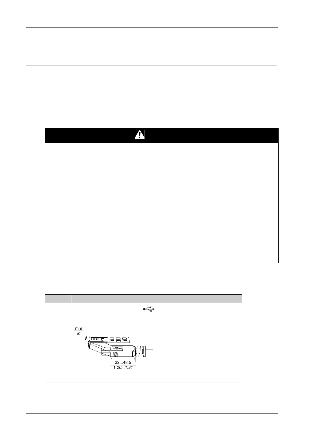
When using a USB device, attach a USB cable clamp to the USB interface to prevent the USB
cable from being disconnected.
POTENTIAL FOR EXPLOSION
Verify the power, input, and output (I/O) wiring are in accordance with Class I, Division 2 wiring
methods.
Substitution of any components may impair suitability for Class I, Division 2.
Do not disconnect equipment while the circuit is live or unless the area is known to be free of
ignitable concentrations.
Remove power before attaching or detaching any connectors to or from this product.
Ensure that power, communication, and accessory connections do not place excessive stress
on the ports. Consider the vibration in the environment when making this determination.
Securely attach power, communication, and external accessory cables to the panel or cabinet.
Use either a USB cable by Pro-face or a commercial-type USB cable.
Use only non-incendive USB configurations.
The associated non-incendive field wiring apparatus shall not be connected in parallel unless
approved by the associated non-incendive apparatus.
This product is suitable for use and provides non-incendive field wiring to apparatus in Class
I, Division 2, Groups A, B, C, D.
Failure to follow these instructions will result in death or serious injury.
FP5000 Series User Manual
DANGER
Attaching USB Clamp (Type B)
NOTE: Watch your fingers. The edge of the clip is sharp.
Step Action
1
Mount the clip to the USB mark connector shell so that it overlaps. The
clip matches the 32 to 48.5 mm (1.26 to 1.91 in) length of the USB connector.
67
Page 68
Installation and Wiring
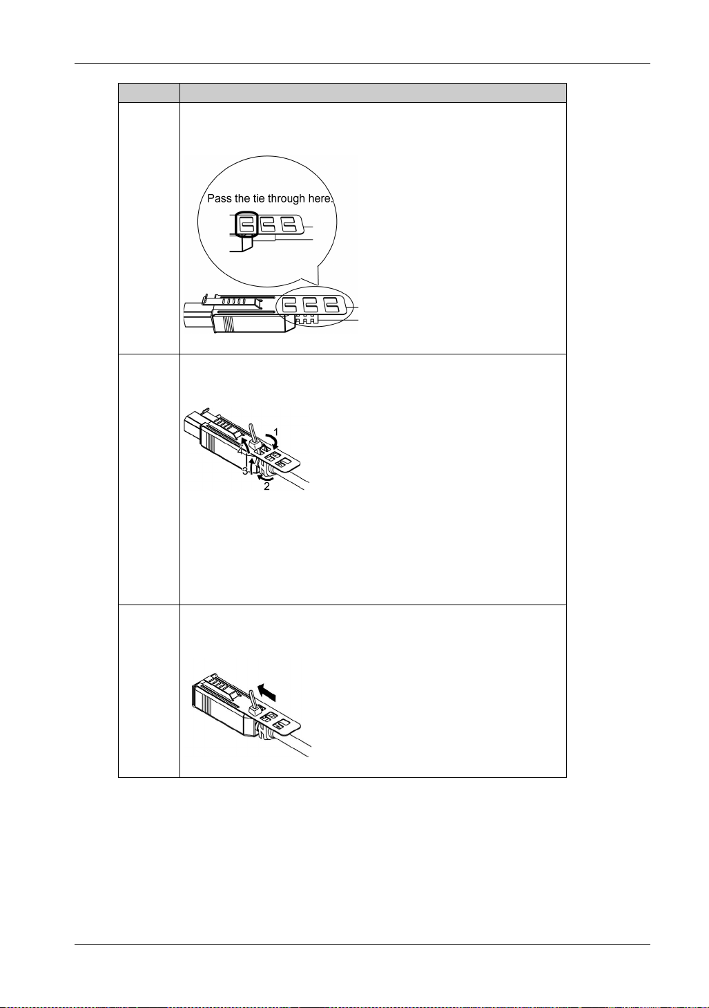
Step Action
2 Align the clip and the USB cable connector shell. Adjust the position of the
3 As shown, pass the tie through the clip hole. Next, turn the tie and pass it
holes where the clip is attached. To ensure stability, select the clip-hole
position that is closest to the base of the connector shell.
through the head so that the USB cable can pass through the center of the tie
loop. The clip is now attached to the USB cable.
NOTE:
Check the direction of the head beforehand. Make sure the USB cable is
through the center of the tie loop and that the tie can pass through the head.
If the provided ties are lost, you can substitute them with
PFXZFP5000USCLB1 (by Pro-face) or commercially available ties of
4.8 mm (0.19 in) width and 1.3 mm (0.05 in) thickness.
4 While pressing the grip on the clip, insert the cable from Step 3 all the way into
the USB host interface. Make sure that the clip tab is secured to the USB cable
attached to this product.
68
Page 69

Removing USB Clamp (Type B)
Remove the USB cable while pushing the grip section of the clip.
FP5000 Series User Manual
69
Page 70
Installation and Wiring
Front USB Cover
Section 6.4
Front USB Cover
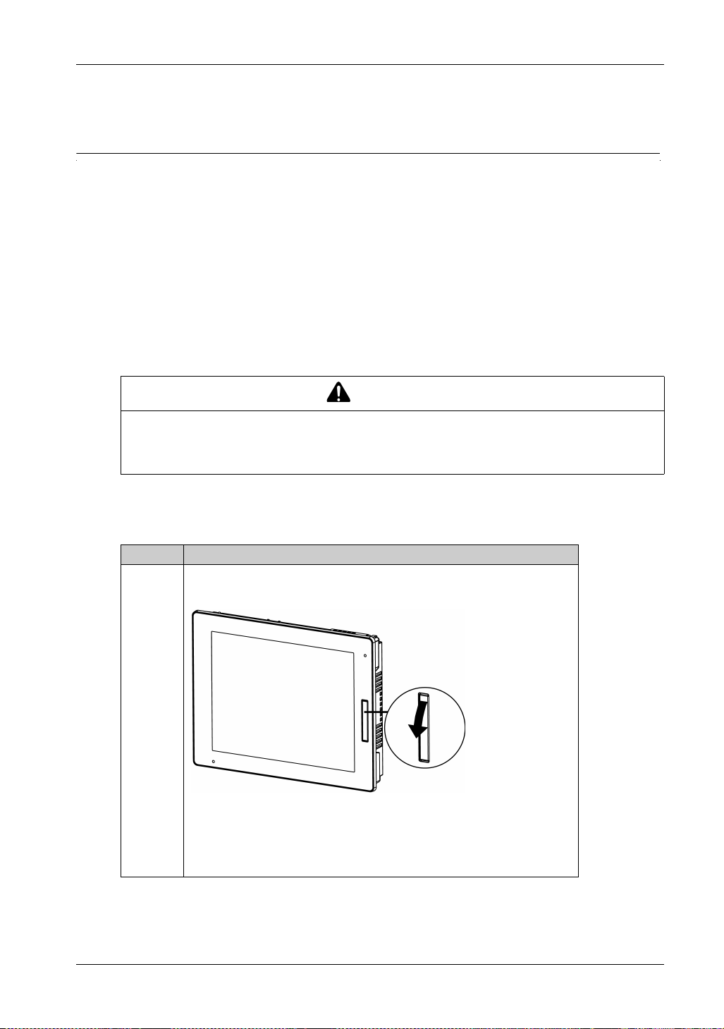
Opening the Front USB Cover
When using a factory-installed front USB cover (without screw), the front surface is IP65F
*1
or Type 1 Enclosure. When using a front USB cover (with screw*2) by Pro-face (Model
P67F
Number PFXZCDCVUS1), the front surface is IP66F
Only) or Type 13 Enclosure.
Regardless of using a factory-installed front USB cover or a front USB cover with screw, when the
cover is open, the front surface is Type 1 Enclosure.
RISK OF INJURY
When opening the Front USB Cover, be careful not to injure your fingers.
Failure to follow these instructions can result in injury or equipment damage.
*1
, IP67F*1, Type 1, Type 4X (Indoor Use
CAUTION
*1
,
*1 IP65F, IP66F and IP67F are not part of the UL certification.
*2 The necessary torque is 0.5 N•m (4.4 lb-in).
Step Action
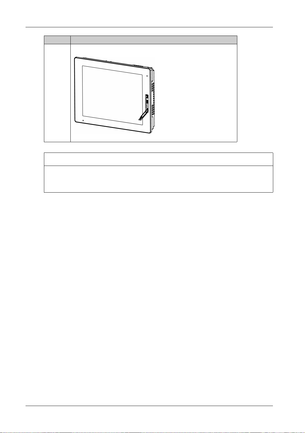
1 Place your finger or a tool (such as a screwdriver) in the gap on the top of the
front USB cover and pull down as illustrated.
NOTE:
When using the front USB cover by Pro-face (Model Number
PFXZCDCVUS1), loosen the top screw using a Phillips screwdriver.
The required torque is 0.5 N•m (4.4 lb-in).
70
Page 71
FP5000 Series User Manual
Step Action
2 The USB interface can be seen once you pull down the front USB cover.
NOTICE
BROKEN ENCLOSURE
Do not exert more than 0.5 N•m (4.4 lb•in) of torque when tightening the screw.
Failure to follow these instructions can result in equipment damage.
71
Page 72

Installation and Wiring
72
Page 73
FP5000 Series User Manual
System Specifications an d Launcher
iDisplay_PF 12/2017
System Specifications and Launcher
Chapter 7
System Specifications and Launcher
Introduction
This chapter describes the system specifications for this product and the Launcher.
What Is in This Chapter?
This chapter contains the following sections:
Section Topic Page
7.1 System Specifications 74
7.2 Launcher 80
FP5000 Series User Manual
73
Page 74
System Specifications and Launcher
System Specifications
Section 7.1
System Specifications
What Is in This Section?
This section contains the following topics:
Operating System, Drivers, Utilities 75
Settings Workflow 76
Installing the Drivers 77
Installing the Utilities 79
Topic Page
74
Page 75
Operating System, Drivers, Utilities
Introduction
This section describes the required software environment for this product.
Compatible Operating Systems
Windows
Windows
Windows
Windows
Windows
*1 For supported models, contact customer support.
Dedicated drivers and utilities
Dedicated drivers and utilities are required for touch input data communication between this
product and the host, and adjustment of the screen display.
You can download the drivers and utilities from our support site at http://www.pro-
face.com/trans/en/manual/1001.html.
®
XP 32-bit
®
7 32-bit/64-bit
®
8 32-bit/64-bit
®
Embedded Standard 2009 for Pro-face products
®
Embedded Standard 7 for Pro-face products
FP5000 Series User Manual
*1
*1
Name Description
Communication driver This driver enables communication between this
product and the utilities (see page 77).
Touch panel driver (only when using
Driver
Windows
®
XP)
Launcher
Brightness
Buzzer
Front USB
Utility
T/P (Touch Panels) Calibration
Launcher Settings
This driver sets cursor movement on the target
display for touch operations (see page 78).
(see page 81)
75
Page 76
System Specifications and Launcher
Settings Workflow
Follow the steps below to configure the software.
Step Action
1 Configure the display settings from the screen properties (Screen Resolution) for your host.
2 Install the drivers (see page 77).
3 Install the utilities (see page 79).
4 Configure Tablet PC (see page 87).
5 Configure Launcher Settings (see page 84).
6 Configure the following as needed, in any order.
Brightness (see page 83)
Buzzer (see page 83)
Front USB (see page 83)
T/P Calibration (see page 84)
Display (see page 87)
Power Option (see page 87)
When changing PC Settings (Display, Power Option, Tablet PC), always ensure that the Write
Filter is disabled. If the Write Filter is enabled, the setting information will be erased when the
operating system is restarted. After you change the setting, we recommend that you re-enable the
Write Filter.
76
Page 77
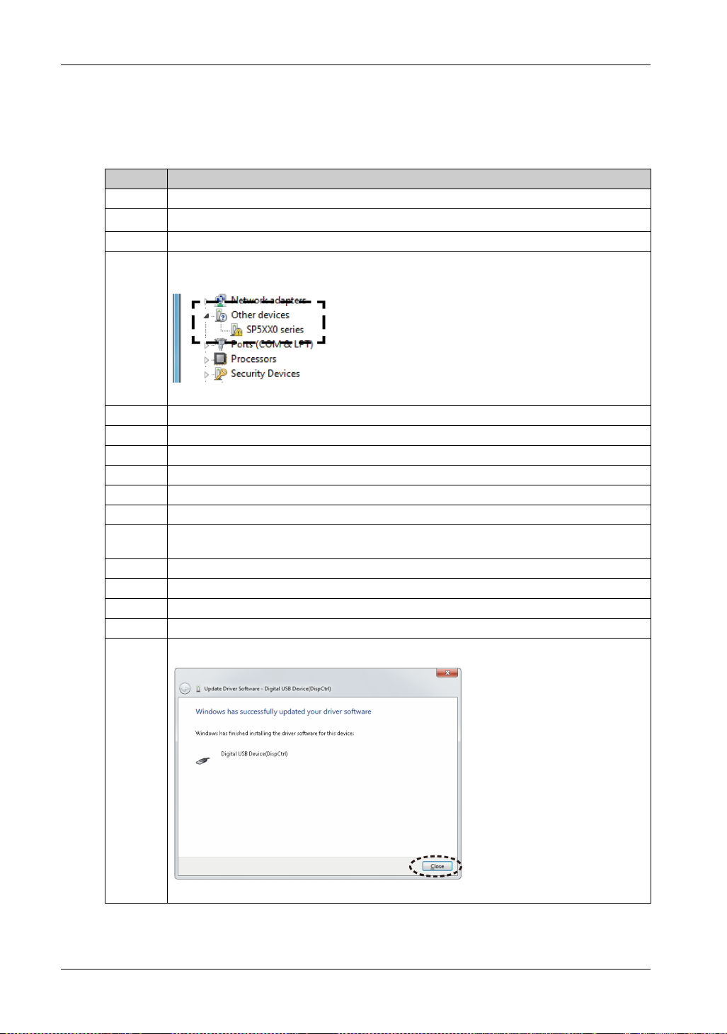
Installing the Drivers
Communication driver
Step Action
1 Connect this product to the host with a DVI-D cable and USB cable (see page 24).
2
Turn on this product and the host, and start Windows
3 Download the drivers onto the host (see page 75).
4From Control Panel Device manager, check that SP5XX0 series is displayed under Other
devices.
5 Right click SP5XX0 series, and select Update Driver Software.
6 Click Browse my computer for driver software.
7 Click Let me pick from a list of device drivers on my computer.
8 Click Next.
9 Click Have Disk.
10 Click Browse.
11 From the folder containing the downloaded drivers, open Drivers CommunicationDriver
12 Select dispctrl.inf and click Open.
13 Click OK.
14 Click Next.
15 Click Install.
16 Click Close to complete the installation.
the folder for your operating system.
FP5000 Series User Manual
®
.
77
Page 78
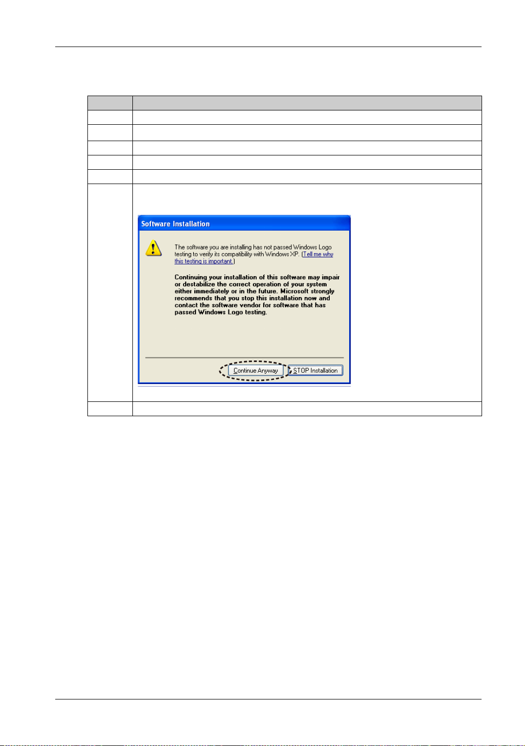
System Specifications and Launcher
Touch panel driver (only when using Windows® XP)
Step Action
1 Connect this product to the host with a DVI-D cable and USB cable (see page 24).
2
Turn on this product and the host, and start Windows
3 Touch the screen and confirm that the curser moves.
4 Download the drivers onto the host (see page 75).
5 From the folder containing the downloaded drivers, open Drivers TouchPanelDriver wxp.
6Run Setup.bat, and follow the on-screen instructions to install the drivers. If the following dialog
box appears during installation, select Continue Anyway.
®
.
7 Click Finish to complete the installation.
78
Page 79
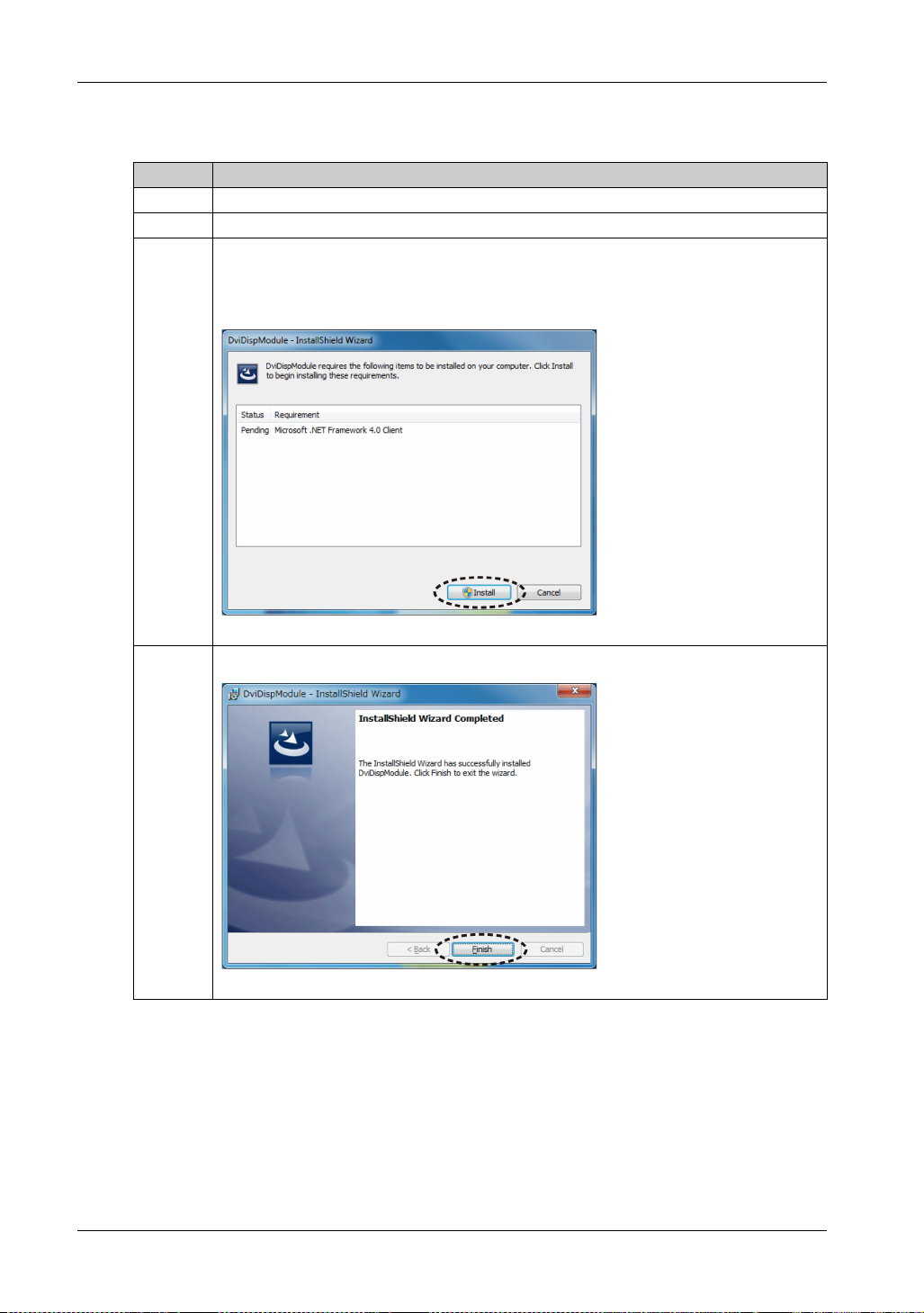
Installing the Utilities
Step Action
1 Download the utilities onto the host. (see page 75)
2 From the folder containing the downloaded utilities, open Drivers Utilities.
3Run setup.exe, and follow the on-screen instructions to install the utilities.
NOTE: To use these utilities, Microsoft
Framework is not installed on your host, follow the on-screen instructions to install it.
FP5000 Series User Manual
®
.NET Framework is required. If Microsoft®.NET
4 Click Finish to complete the installation.
79
Page 80

System Specifications and Launcher
Launcher
Section 7.2
Launcher
What Is in This Section?
This section contains the following topics:
About the Launcher 81
Display Settings 83
PC Settings 87
Topic Page
80
Page 81
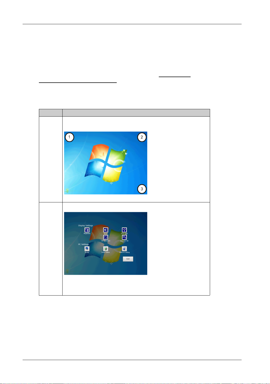
About the Launcher
Introduction
The Launcher is a utility that displays icons to configure settings on this product with convenient
touch operation.
NOTE: Before using the Launcher, you need to install the required drivers and utilities. You can
download the drivers and utilities from our support site at http://www.pro-
face.com/trans/en/manual/1001.html. For more detailed information, refer to Installing the Drivers
(see page 77) and Installing the Utilities (see page 79).
How to Display the Launcher
Step Action
1 On this product’s screen, press and hold the locations below in the order
indicated within 5 seconds.
FP5000 Series User Manual
2 The Launcher is displayed.
NOTE: If multiple displays are connected to the host, the Launcher is displayed
on the primary display (main display) by default in the factory setting.
81
Page 82
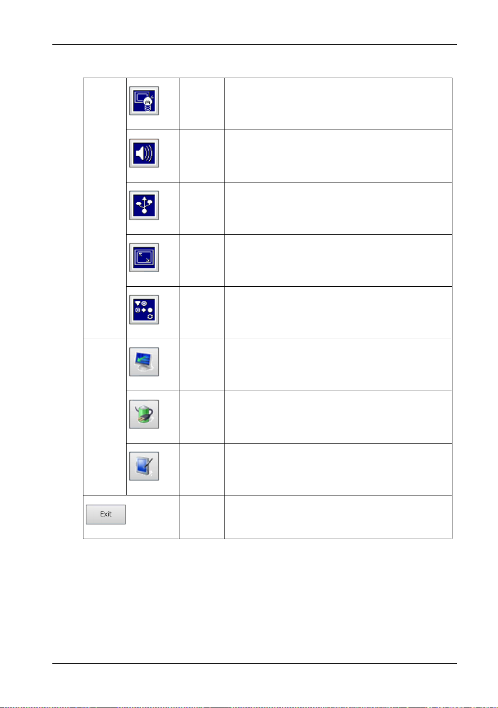
System Specifications and Launcher
Icons
Display
settings
PC
settings
Brightness Sets the backlight brightness. You can select Manual or Auto.
When Auto is selected, a brightness sensor automatically adjusts
the brightness (see page 83).
Buzzer Sets the sound on/off when starting the Launcher and performing
touch operations (see page 83).
Front USB Enables/disables the front USB port (see page 83).
T/P
Calibrates the touch coordinates (see page 84).
Calibration
Launcher
Set
Sets the display parameters so that the screen can be adjusted
through the Launcher (see page 84).
Display Adjusts the contrast and black level of the display. This is a
standard feature of Windows
®
(see page 87).
82
Power
Option
Sets the amount of time before the display is turned off. This is a
®
standard feature of Windows
(see page 87).
Tablet PC Makes the host recognize that the display is touchscreen.This is
a standard feature of Windows
®
7 or later (see page 87).
Exit Closes the Launcher.
NOTE: Touch the icon and the associated dialog box is displayed on releasing the finger.
Page 83
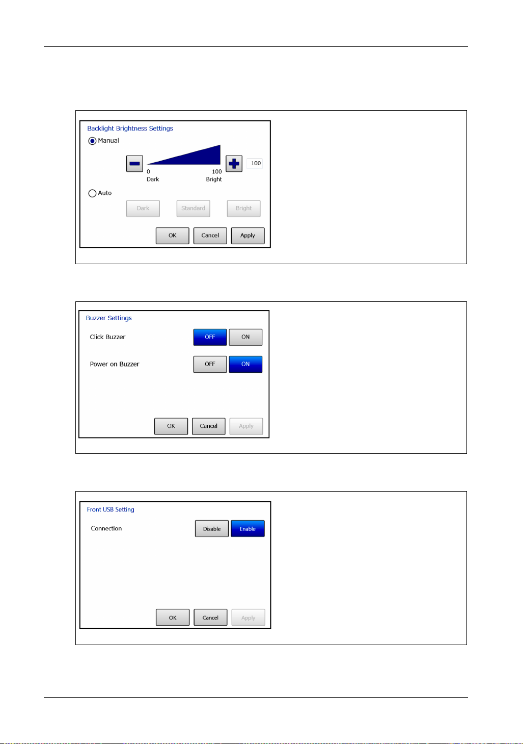
Display Settings
Brightness
Buzzer
FP5000 Series User Manual
Manual: Sets the brightness to a fixed
value from 0 to 100.
Auto: Automatically adjusts the brightness
to the selected level using a brightness
sensor.
Click Buzzer: Sets the sound on/off when
you perform touch-panel operations.
Front USB
Power on Buzzer: Sets the sound on/off
when you turn on this product.
Enables/disables the front USB port.
83
Page 84
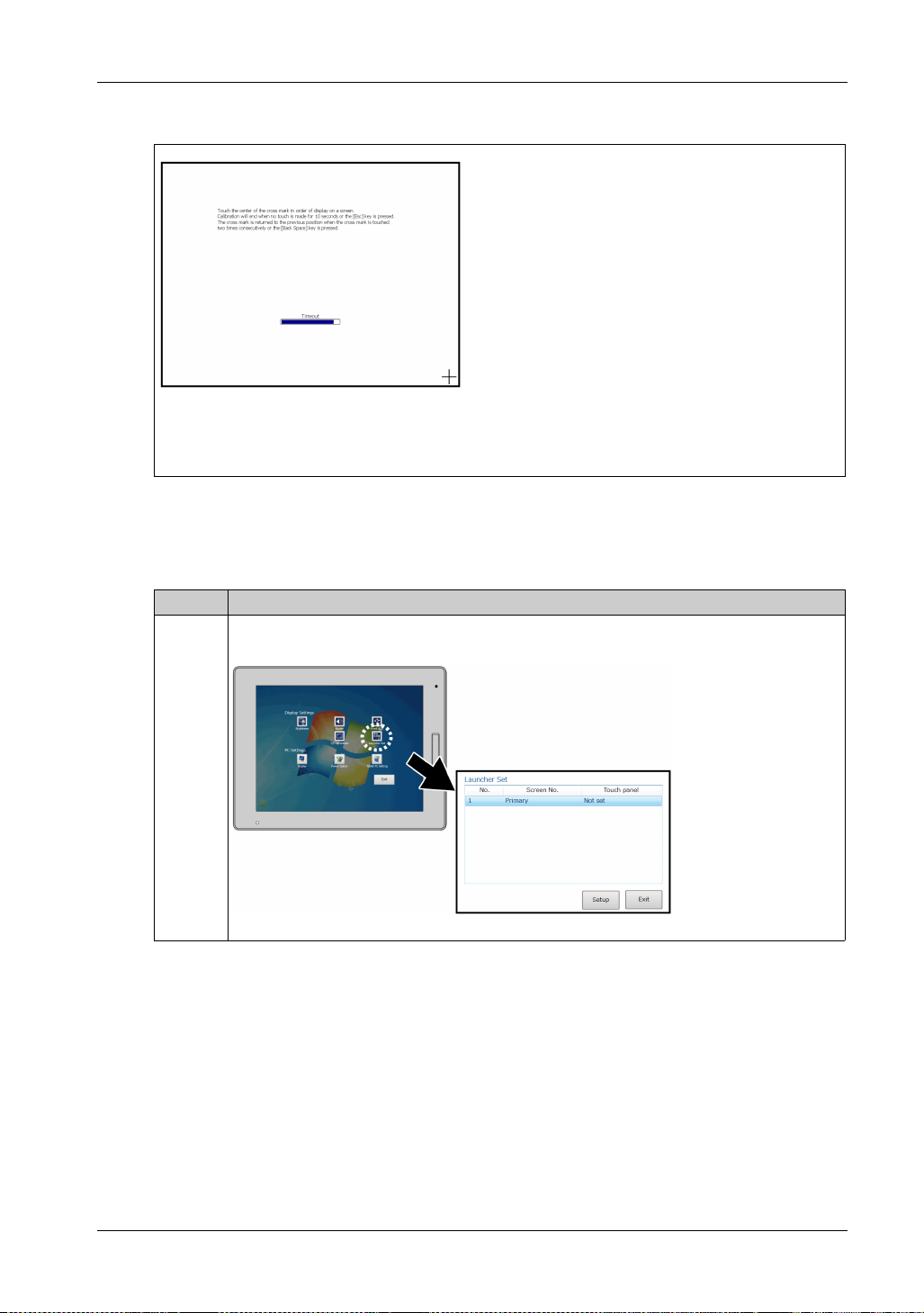
System Specifications and Launcher
T/P (Touch Panel) Calibration
NOTE: Do not calibrate the touch panel using Adjustment in
Tablet PC. If touch panel calibration is required, be sure to use
T/P Calibration.
Launcher Settings
After you connect this product to the host, set the display parameters so that the screen can be
adjusted through the Launcher.
Calibrates the touch panel via the onscreen instructions.
Step Action
1 Touch or click the Launcher Set icon. In the Launcher Set dialog box, the FP5000 Series
display connected to the host is displayed.
84
Page 85
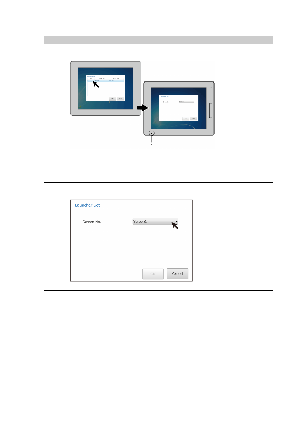
FP5000 Series User Manual
Step Action
2 Select any number. The status LED on the display for the selected number alternates between
green and orange.
1 Status LED
NOTE: If multiple FP5000 Series displays are connected, you cannot determine through the
display which number corresponds to which display. Check the status LED.
3 Select the Screen No (screen identification number) for the display where the status LED is
alternating green and orange.
85
Page 86
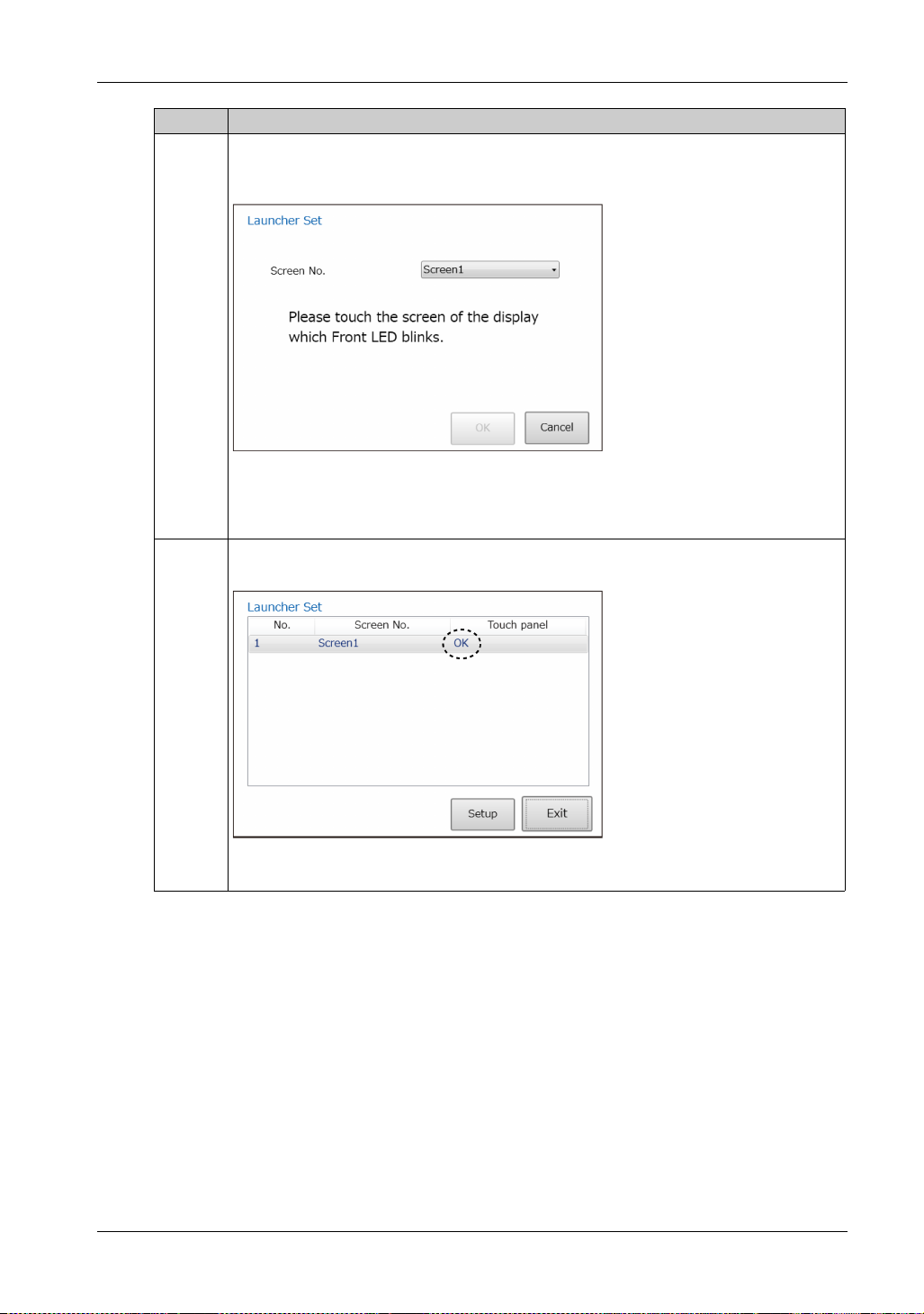
System Specifications and Launcher
Step Action
4 Following the dialog box instructions, touch the screen that has its status LED alternating
between green and orange. After displaying the Launcher (see page 81), you can configure the
settings for that screen.
NOTE: If multiple displays are connected in extension mode (Extend these displays is
selected), confirm that the above message appears on the display where the status LED is
alternating green and orange, and touch this screen.
5 If multiple FP5000 Series displays are connected, repeat Steps 2 to 4 for each display as
required.
86
NOTE: When the FP5000 Series display is configured, OK appears in the Touch panel column.
NOTE: If you extend your desktop across multiple monitors connected to DVI-D ports, and you
switch their DVI-D cables, touching one screen will operate the mouse pointer on the other screen.
If you switch DVI-D cables, change the Screen No setting on the Launcher.
Page 87
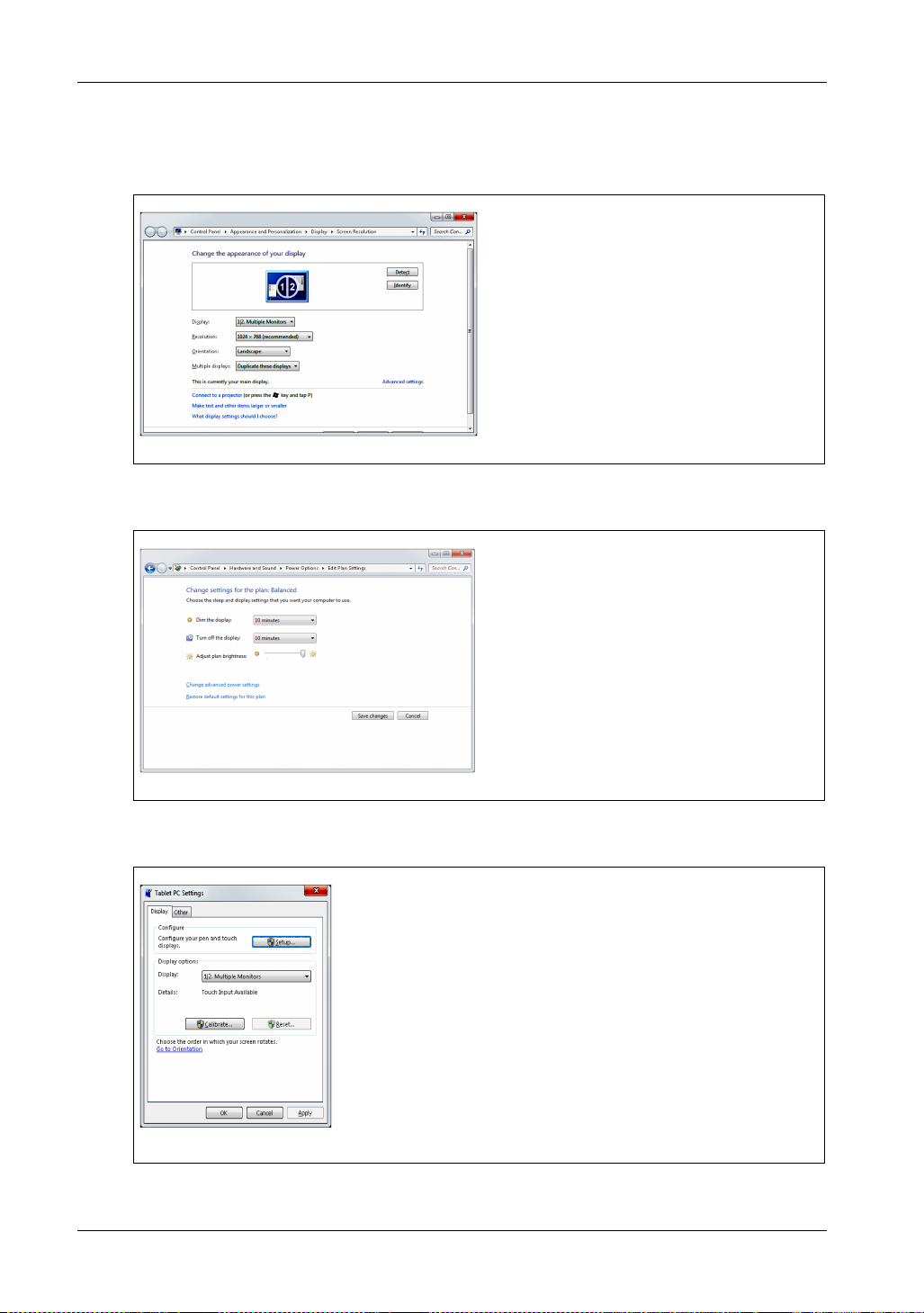
PC Settings
Display
Power Option
FP5000 Series User Manual
The Windows® standard setting window is
displayed. For adjustment of screen
contrast and black level, from Advanced
settings, make the settings in the setting
screen for your graphic driver.
NOTE: When using Windows XP or
Windows Embedded Standard 2009, for
rotation settings use Standard or 180
The Windows® standard setting window is
displayed. Set the time duration before this
product automatically turns off and other
settings.
Tablet PC
The Windows® standard setting window is
displayed. In Setup, confirm that the
display is recognized as touchscreen.
NOTE:
• To enable this setting, on the host open
Control Panel Administrative Tools
Services, and then enable the Tablet
PC Input Service (set its Startup type to
either Manual or Automatic).
• Do not calibrate the touch panel using
Adjustment in Tablet PC. If touch panel
calibration is required, be sure to use T/P
Calibration.
87
Page 88

System Specifications and Launcher
88
Page 89
FP5000 Series User Manual
Maintenance
iDisplay_PF 12/2017
Maintenance
Chapter 8
Maintenance
Introduction
This chapter explains how to maintain this product.
What Is in This Chapter?
This chapter contains the following topics:
Regular Cleaning 90
Periodic Check Points 91
Replacing the Installation Gasket 92
Replacing the Backlight 93
Troubleshooting Checklist 94
After-sales Service 95
FP5000 Series User Manual
Topic Page
89
Page 90

Maintenance
Regular Cleaning
Cleaning the display
EQUIPMENT DAMAGE
Power off this product before cleaning it.
Do not use hard or pointed objects to operate the touch panel as you may damage the panel
surface.
Do not use paint thinner, organic solvents, or a strong acid compound to clean the unit.
Failure to follow these instructions can result in equipment damage.
When the surface or the frame of the display gets dirty, soak a soft cloth in water with a neutral
detergent, wring the cloth tightly and wipe the display.
NOTICE
90
Page 91

Periodic Check Points
Operation Environment
Is the operating temperature within the allowable range? (0...60 C [32...140 F])
Is the operating humidity within the specified range? (10% RH to 90% RH, dry bulb temperature
of 39 C [102.2 F] or less)
Is the operating atmosphere free of corrosive gasses?
When this product is inside a panel, the ambient environment refers to the interior of the panel.
Electrical Specifications
Is the input voltage appropriate? (10.8...28.8 Vdc)
Are all power cords and cables connected properly? Are there any loose cables?
Are all mounting brackets holding the unit securely?
Are there scratches or traces of dirt on the installation gasket?
Unit Disposal
When disposing this product, dispose it in a manner appropriate to, and in accordance with, your
country’s industrial machinery disposal/recycling standards.
FP5000 Series User Manual
91
Page 92
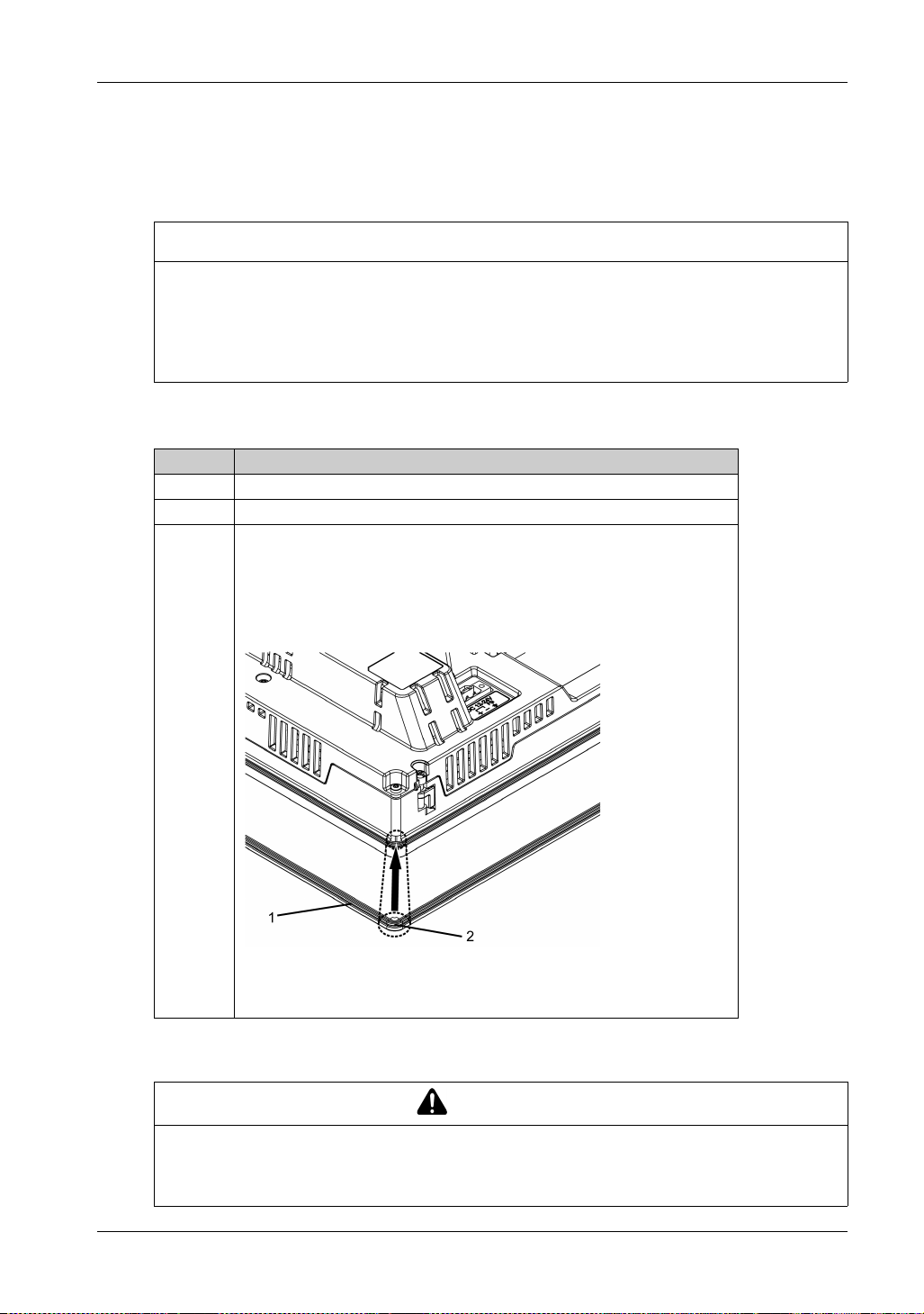
Maintenance
Replacing the Installation Gasket
Introduction
The installation gasket provides protection against dust and moisture.
GASKET AGING
Inspect the gasket periodically as required by your operating environment to keep the initial IP
level.
Change the gasket at least once a year, or as soon as scratches or dirt become visible.
Failure to follow these instructions can result in equipment damage.
Installing the Installation Gasket
Step Action
1 Place this product on a flat, level surface, with the display face pointing down.
2 Remove the gasket from this product.
3 Attach the new gasket to this product. Insert the protrusions from the four
corners of the gasket into the corresponding holes in the corners of this
product.
NOTE: When using a tool to insert the gasket, make sure the tool does not
catch the rubber gasket and cause a tear.
NOTICE
92
1 Installation Gasket
2 Protruding point
The gasket must be inserted correctly into the groove for moisture resistance for this product.
CAUTION
EQUIPMENT DAMAGE
Since the gasket is flexible but not elastic, be careful not to stretch it unnecessarily.
Failure to follow these instructions can result in injury or equipment damage.
Page 93

Replacing the Backlight
Not user replaceable. When replacement is required, contact customer support.
FP5000 Series User Manual
93
Page 94
Maintenance
Troubleshooting Checklist
Introduction
When a problem occurs, make sure to go through the checklist and follow the instructions given.
Here are the main issues that may occur when using this product:
The display is blank:
No display appears after this product is switched on
The screen disappears during standard operation
The screen does not display normally
The touch panel does not respond
NOTE: If the following checklists do not solve your problem, please contact customer support.
No Display
The table below suggests actions to take if this product’s display is blank or if the screen turns itself
off.
Step Check/Operation Solution
1 Is the status LED red?
2 Is the status LED blinking orange?
3 Is the status LED green?
4 Is the status LED fading in and out?
5 Are you using the correct voltage to power the
product?
6 Turn off the power. Go to Step 7.
7 Is the power cable connected properly?
8 Did you solve your problem? If none of the previous steps fixed the problem,
If No, go to Step 2.
If Yes, go to Step 8.
If No, go to Step 3.
If Yes, check the cable connection and
restart the host.
If No, go to Step 4.
If Yes, go to Step 8.
If No, go to Step 5.
If Yes, reconnect the DVI-D cable properly.
If No, use the correct voltage (see page 33).
If Yes, go to Step 6.
If No, connect it properly (see page 64).
If Yes, go to Step 8.
then there is a problem with the product.
Contact customer support.
94
Page 95

After-sales Service
For details on after-sales service, refer to our website at http://www.proface.com/trans/en/manual/1001.html
FP5000 Series User Manual
95
 Loading...