

Page 1

FP-3500T/3600T/3650T
)376HULHV
User Manual
8VHU0DQXDO
Series
Page 2

Preface
Thank you for purchasing Digital’s TFT type color display panel, the ‘FP-3900T series’ (hereafter referred to as the FP
unit).
Please read this manual completely to insure the correct use and complete understanding of the FP unit’s functions.
NOTICE
1. Copying this manual’s contents, either in whole or in part, is prohibited without the express permission of Digital
Electronics Corporation, Japan.
2. The information contained in this manual is subject to change without notice.
3. If you find any errors or omissions in this document, please contact Digital Electronics Corporation to report your
findings.
4. Please be aware that Digital Electronics Corporation shall not be held liable by the user for any damages, losses,
or third party claims arising from the uses of this product.
Product names used in this manual are the trademarks / registere d trademarks of their respective owners.
© 2007 Digital Electronics Corporation. All rights reserved.
1
Page 3
Essential Safety Precautions
This manual describes safety instructions for correct use of the FP unit. Pl ease keep this manual cl ose at hand and refer to
it when necessary.
Safety Icons
Throughout this manual, these icons provide essential safety information for FP operation procedures requiring special
attention. These icons indicate the following levels of danger:
Indicates situations where severe bodily injury, death or major equipment
damage can occur.
Indicates situations where slight bodily injury or minor equipment damage can
occur.
Indicates actions or procedures that should NOT be performed.
Indicates actions or procedures that MUST be performed to ensure correct
unit operation.
Because of the ever present danger of electrical shock, be sure to unplug the power cab le from the FP unit before
plugging the cable’s other end into the wall.
Do not use power in excess of the unit’s specified voltage range since it may cause a fire or electric shock.
Because the FP unit contains high voltage parts, an electric shock can occur when disassembling the unit. Therefore,
be sure to always unplug the unit before disassembling it.
Do not modify the FP unit in any way, since it may cause a fire or electric shock.
Do not use touch panel keys to perform life-threatening or vitally important safety functions. Use separate mecha nical switches for such keys.
Do not use the FP unit as a warning device for critical alarms that can cause serious operator injury, mac hine damage
or production stoppage. Critical alarm indicators and their control/activator units must be designed using stand-alone
hardware and/or mechanical interlocks.
2
Page 4
In a situation that a detection function for the backlight burnout has been ineffective, if a burnout of the backlight
happened, unlike in an extinction condition of the backlight of FP, the touch panel is still active. If an operator fails
to notice that the backlight is burned out and touches the panel, a potentially dangerous machine miss-operation can
occur. Therefore, do not set up switches on the touch panel of an FP that are likely to cause human error or physical
damage triggered by mis-operation.
If your FP’s backlight suddenly turns OFF, use the following steps to determine if the backlight is actually burned
out.
1) If your current FP application or Auto off Disp fu nction is not set, and the screen has gone blank, your backlight is
burned out.
2) If your current FP application or Auto off Disp function is set, and if touching the screen does not cause the display to reappear, your backlight has been burned out.
If substantial amounts of metallic dust, water or liquids enter the FP unit, turn off the power supply immediately,
unplug the power cord, and contact your local FP distributor.
When installing the FP unit, be sure to follow the instructions given in “Chapter 3 Installation and Wiring,” to insure
it is done correctly.
Do not use the FP in an environment with flammable gas, since it may cause an explosion.
The FP is not appropriate for use with aircraft control devices, aerospace equipment, central trunk data transmission
(communication) devices, nuclear power control devices, or medical life support equipment, due to these devices’
inherent requirements of extremely high levels of safety and reliability.
When using the FP with transportation vehicles (trains, cars and ships), disaster and crime prevention devices, various types of safety equipment, non-life support related medical devices, etc, redundant and/or failsafe system
designs should be used to ensure the proper degree of reliability and safety.
Do not press the screen’s touch surface too strongly with either your finger or a hard object, since the touch surface
may be damaged.
When the surface of the display screen becomes dirty or smudged, clean the display with a cloth soaked in a neutral
detergent. Do not use paint thinner or organic solvent.
Do not press on the touch panel's face with sharp objects, such as a mechanical pencil or screwdriver, since it might
damage the LCD panel.
A void using or storing the FP in direct sunlight, excessivel y dusty or dirty environments, or where c hemical s or their
vapors are present in the air.
3
Page 5

Avoid restricting the FP’s natural ventilation, or storing and using the FP in an environment that will increase the
FP’s internal te mperature.
Do not use the FP in areas where sudden, large changes in temperature may occur. These changes can cause condensation to form inside the unit, possibly causing an accident.
Do not store or use the FP where chemicals (such as organic solvents, etc.) and acids can evaporate, or where chemicals and acids are present in the air.
When the product is disposed of, it should be done so according to your country’s regulations for similar types of
industrial waste.
LCD Panel Usage Precautions
Notes on the FP’s Liquid Crystal Display (LCD)
For detailed LCD information, please contact Digital’s Development department, Product Quality Assurance group.
• The FP’s LCD contains a strong irritant. If the panel is damaged and the LCD unit’s liquid contacts your skin, be sure
to wash it with running water for at least 15 minutes. If any of this liquid should enter your eye, be sure to flush the
eye with running water for more than 15 minutes, and see a doctor immediately.
• The FP unit’s LCD screen may flicker or show unevenness in the brightness of certain images or at some contrast
settings. This is an LCD characteristics and not a product defect.
• There’s an individual difference in brightness and tone of LCD screen. Please be aware of this difference before using
the lined-up plural units.
• Some of FP unit's LCD screens may contain black and white colored pixels. This is an LCD characteristic and not a
product defect.
• The displayed color will look different when viewed from an angle outside the specified view angle. This is also
normal.
• Displaying a single screen image for long periods of time can cause an afterimage to remain. To correct this, turn the
unit OFF for 5 or 10 minutes, then turn it ON again. This phenomenon is a common attribute of the LCD unit’s, and
not a defect. To prevent this effect, you can:
- use the Display OFF feature, if the same image is to be displayed for a long period of time.
- change the screen display periodically to prevent the displaying of a single image for a long period of time.
4
Page 6

Connecting the FP to a PC
The FP-3900TSeries units are designed as a standard SXGA display.
Be aware that some types of SXGA equipment may not be within the ranges specified in this document, and, therefore,
cannot be connected to the FP.
Also, if you change your PC’s SXGA board, there is the possibility that the new board may not be able to be connected to
the FP.
SEE
2.3 Interface Specifications (page2-5)
• When a signal timing value not compatible with this device is entered, or if the
entered timing is larger than can be displayed by the dot clock, an “Out of range”
message is displayed. If this occurs, be sure to read your computer’s manual
and enter a value that is compatible with this device.
• If no signal (synchronized signal) is entered, a “No signal” message is displayed.
5
Page 7
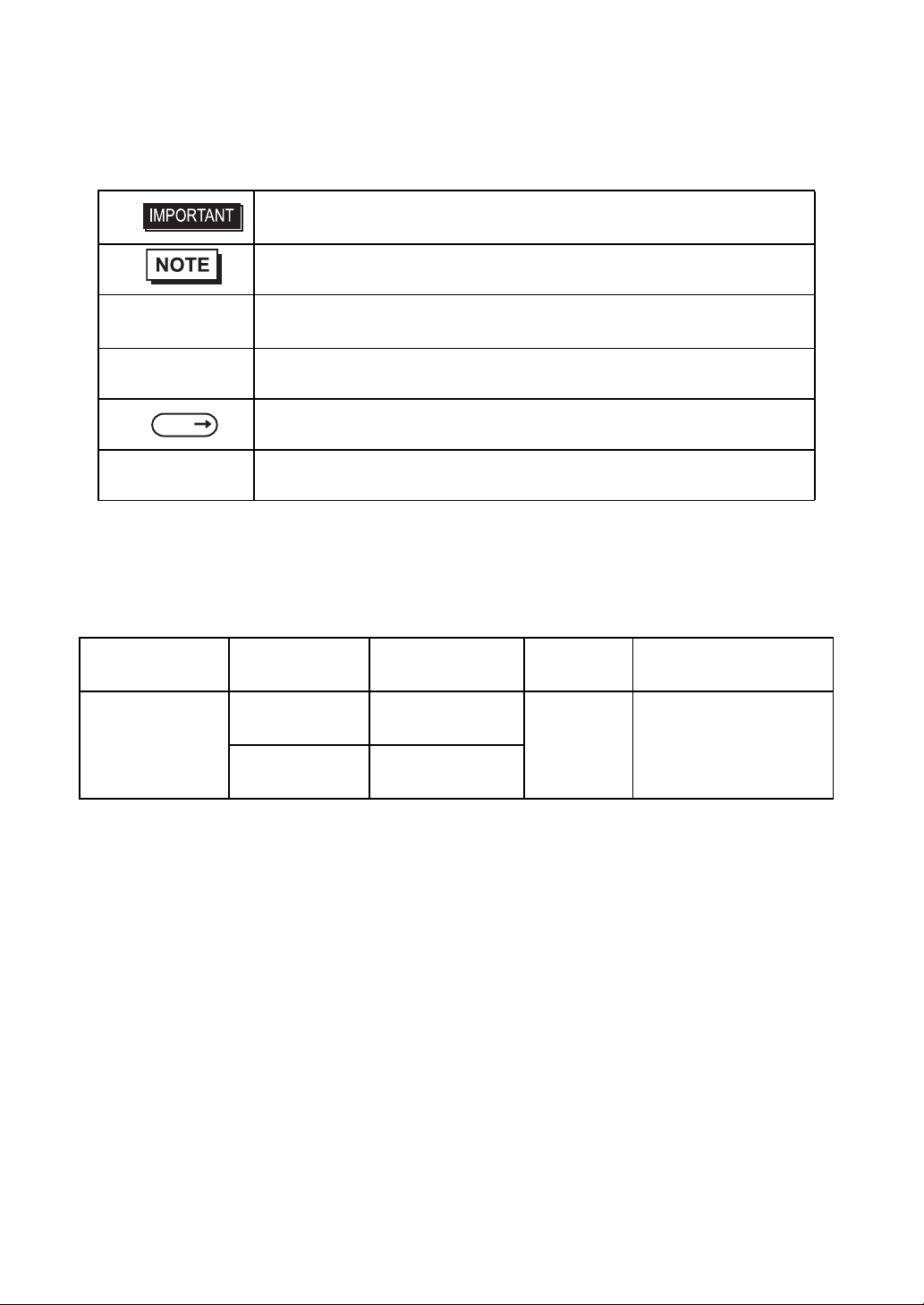
This manual uses the following icons:
Indicates a warning or a product limitation. Be sure to follow the instructions
given with this icon to ensure the safe operation of the FP.
Contains additional or useful information.
Information Symbols
(1) (2)
*1 Indicates useful or important supplemental information.
SEE
FP Series Indicates a generic name for the products of .
Indicates steps used to accomplish a given task.
Be sure to follow these steps in the order they are written.
Indicates pages containing related information.
FP-3900T Series Models
The FP-3900T Series refers to the following FP model numbers:
Series Product Name Model Type
FP-3900T
(with front USB)
FP-3900T Series
FP-3900T
(no front USB)
FP3900-T41-U
FP3900-T41
Power input
type
AC
Standards
UL/c-UL/CSA Approved,
CE Marked
6
Page 8
FP-3900T Series Package Contents
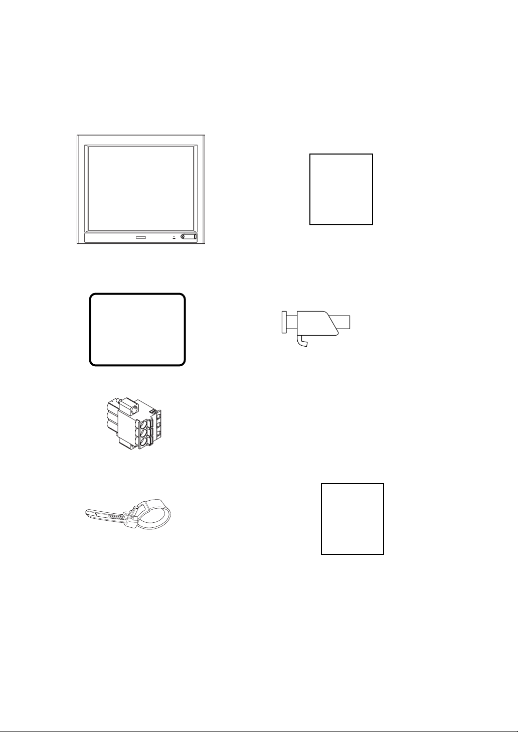
The FP unit’s packing box contains the items listed below. Please check to be sure each item is included and is not damaged.
FP Unit (1) Installation Guide (1)(English / Japanese)
Installation
Guide
(This model is FP3900-T41-U )
Installation Gasket Installation Fasteners (12: 4×3 set)
(attached to the FP unit) (1)
AC Power Connector(atached to the FP unit) (1)
USB Cable Clamp (1) Warning Caution Information (1)
Warning/Cau-
tion
Information
This unit has been carefully packed, with special attention to quality. However, should you find anything damaged or
missing, please contact your local FP distributor immediately.
7
Page 9

Main Features
FP-3900T series displays are equipped with the following features.
• High Quality TFT Color LCD Display
This unit is equipped with a 19.0 inch TFT type color LCD. Its superior brightness and wide viewing angle, not found
in ordinary laptop-type TFT LCDs, widens your scope of applications.
The screen's maximum resolution is 1280 × 1024 pixels and can display 1,677 colors.
• Easy Installation In User’s Cabinets and Panels
The FP’s slim and compact design makes in st allation a snap since it was designed specifically for use as an IA (Industrial Automation) or OA (Office Automation) system monitor. The flat, front panel provides protection equivalent to
the rigorous IP65f standard. Even without its optional protective cover the front panel is highly resistant to both water
and dust.
• Panel can be used as a VGA Display
Since the FP is equipped with an analog RGB interface and a DVI-D Interface, it can be connected to a PC and other,
similar devices. (The PC’s dot clock frequency, however, must be within the standard range.)
• Easy-to-use Built-In Touch Panel
The FP’s built-in touch panel is standard equipment, allowing touch panel data to be output to a host PC via an RS232C cable or USB cable. This is perfect for systems requiring both touch panel operation and data monitoring.
• USB-HUB function (Model T ype:FP3900-T41-U)
The FP-3900T unit has USB-HUB function and can connect USB devices to the front USB connector.
8
Page 10
What is IP65f?
This unit’s protection rating of IP65f is actually a composite code, consisting of the internationally recognized British
“Ingress Protection” standard (BS EN 60529:1992) - “IP65”, and the standard developed by the Japanese Electronics
Manufacturer’s Association (JEM) - “f”. This code is used in this manual to identify a given product’s degree of structural
resistance to a variety of environmental elements and thus, prevent problems or accidents related to the inappropriate use
of a product. The individual meaning of each character of this code is explained below.
IP 6 5 f
(1) (2) (3) (4)
(1) Designates the type of protection provided.
Indicates the degree of protection provided to the human body by the unit, and the deg ree of
(2)
protection provided by the unit's front face from particles/dust intrusion into the interior of the
unit. Here, “6” indicates that the unit is completely protected from dust intrusio n.
Indicates the degree of protection provided by the unit’s front face from water intrusion into
(3)
the interior of the unit. Here, “5” indicates that the unit is protected from water intrusion from
a direct water jet.
Indicates the degree of protection provided by the unit’s front face from oil particle intrusion
(4)
into the interior of the unit. Here, “f” indicates that the unit is co mpl e tely protected from oil
intrusion via either oil particles or oil splashes from any direction (to the front panel).
Required Software /Reference Manual
An FP-3900Tseries unit needs the following software for operation. As the FP user manual, provided by PDF media,
describes its details, download the manual below and get the further information. Vi sit our support site below and get both
software and reference manual.
Digital Electronics Corporation’s support site - Otasuke Pro!
http://www.pro-face.com/otasuke/
• Software: Mouse Emulation Software
• Manual: FP-3900T series User Manual
• For use of USB for sending touch data, the number of the calibration point of
mouse emulation software should be 9. (The initial setting is 4.)
If you don't change the setting values, the touch position may not be accurate, a
little off the point.
9
Page 11
UL/c-UL/CSA Approval
FP-3900T Series is a UL/c-UL/CSA listed product. (UL File No.E220851, CSA File No. 219866)
Those products conform to the following standards:
• UL508 Industrial Control Equipment
• CSA-C22.2, No.142-M1987 Process Control Equipment
Product Model No. UL Registration Model No.
FP3900-T41-U
3582701-01
FP3900-T41
.
<Cautions>
• The FP must be used as a built-in component of an end-use product.
• This unit should be installed in the front face of a metal panel.
• If this unit is installed so as to cool itself naturally, be sure to install it in a vertical panel .
Also, be sure that the FP unit is mounted at least 100 mm away from any adjacent struct ures or equipment. If these
requirements are not met, the heat generated by the FP unit’s internal components may cause the unit to fail to meet
UL/c-UL standard requirements.
• For use in Polluition Degree 2 environment
• For use on a flat surface of a Type 1 Enclosure.
10
Page 12

CE Marking
The FP-3900T Series is a CE marked product that conforms to EMC directives and Low Voltage directives EN55011
Class A, EN61000-6-2 and EN60950-1 First Edition.
*For detailed CE marking information, contact your local FP distributor.
11
Page 13

MEMO
12
Page 14

Table of Contents
Preface...........................................................................................................1
Essential Safety Precautions ........................................................................2
Connecting the FP to a PC ...........................................................................5
Information Symbols .....................................................................................6
FP-3900T Series Models ..............................................................................6
FP-3900T Series Package Contents .............................................................7
Main Features ...............................................................................................8
What is IP65f? ...............................................................................................9
Required Software /Reference Manual .........................................................9
UL/c-UL/CSA Approval ...............................................................................10
CE Marking .................................................................................................11
Table of Contents .........................................................................................13
Chapter 1 Introduction
1.1 System Design................................................................................................1-2
1.2 Optional Equipment........................................................................................1-3
Chapter 2 Specifications
2.1 General Specifications....................................................................................2-2
2.1.1 Electrical specifications.........................................................................................2-2
2.1.2 Environmental specifications ................................................................................2-2
2.1.3 Structural specifications........................................................................................2-3
2.2 Functional Specifications........................... ........... .......... ........... .....................2-4
2.2.1 Performance ........................................................................................................2-4
2.2.2 Display..................................................................................................................2-4
2.3 Interface Specifications...................................................................................2-5
2.3.1 Analog RGB Interface...........................................................................................2-5
2.3.2 DVI-D Interface.....................................................................................................2-7
2.3.3 Serial Interface......................................................................................................2-9
2.3.4 USB Interface (Up-stream port).........................................................................2-10
2.3.5 Front USB Interface (Down-stream port)(FP3710-T41-U model only)...............2-11
2.4 Cable Diagrams............................................................................................2-12
2.4.1 RGB Interface Cable Pin Connections (Option cable: VGA standard) ...............2-12
2.4.2 DVI-D Interface Cable Pin Connections (Option cable)......................................2-13
2.4.3 SIO Interface Cable Pin Connections.................................................................2-14
2.4.4 USB Interface Cable Pin Connections................................................................2-14
2.5 Names and Functions...................................................................................2-15
2.6 Dimensions...................................................................................................2-16
13
Page 15

2.6.1 External Dimensions..... ... .... ... ... ... .... ... ... ... ... .... ... ... ... .........................................2-16
2.6.2 Dimensions with installation fasteners................................................................2-17
2.6.3 Dimensions with Cables............................. ... .... ... ... ... .... ... ... ... .... ... ... ... ...............2-17
2.6.4 Installation Fasteners . ... .......................................... ... .... ... ... ... .... ... ... ... ... ............2-18
2.6.5 Panel Cut Dimensions ........................................................................................2-19
Chapter 3 Installation and Wiring
3.1 Installation.......................................................................................................3-2
3.1.1 Installation Procedures ........................... ... ... .... ... ... ... .... ... ... ... .... ... ... ....................3-2
3.2 Wiring..............................................................................................................3-7
3.2.1 Connecting the Power Cord . ... ... ... .......................................... .... ... ... ... ... .... ... ... ... .3-7
3.2.2 The USB Cable Clamp...................................... ... ... ... .... ... ... ... .... ... ... ... ... .... ... ... ... .3-9
3.2.3 Connecting the Power Supply.............................................................................3-10
3.2.4 Precautions: Grounding.................... ... ... ... .......................................... ... .... ... ... ..3-11
3.2.5 Precautions: Input/Output Signal Lines...............................................................3-11
Chapter 4 Setting up and Adjusting the FP unit
4.1 Operation Mode Setup....................................................................................4-2
4.1.1 Preset Settings and Adjustments for Dip Switch and Slide Switch.......................4-2
4.1.2 Status of Front LED in Operation Modes..............................................................4-3
4.2 Screen Display Adjustment.............................................................................4-4
4.2.1 Calibration of OSD Display Position .....................................................................4-4
4.2.2 OSD Setting Icons ................................................................................................4-6
4.2.3 OSD Setting Item Details......................................................................................4-7
Chapter 5 Touch Panel Data
5.1 Touch Interface Data....................................................................................... 5-2
Chapter 6 Troubleshooting
6.1 Troubleshooting.............................................................................................. 6-2
6.1.1 Possible Device Problems ....................................................................................6-2
6.1.2 No Display.................................. ... .... ... ... .......................................... ... .................6-3
6.1.3 Touch Panel Does Not Respond................... .... ... ... ... .... .......................................6-5
6.2 Error Message................................................................................................6-6
6.2.1 Error Message List................................................................................................6-6
Chapter 7 Maintenance
7.1 Regular Cleaning............................................................................................ 7-2
14
Page 16

7.1.1 Cleaning the Display................... .... .......................................... ... ... ... ... .... ... ... ... ...7-2
7.1.2 Installation Gasket Replacement..........................................................................7-3
7.2 Periodic Check Points.....................................................................................7-4
7.3 Backlight Replacement...................................................................................7-5
15
Page 17

MEMO
16
Page 18

1 Introduction
1. System Design
2. Optional Equipment
This chapter describes the outline of FP Series.
1-1
Page 19
FP-3900T Series User Manual
1.1 System Design
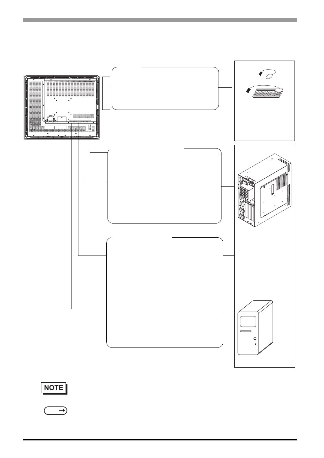
The FP can be connected to Pro-face’s PS-2000B or to a Windows® compatible PC.
FP unit
USB I/F
For downstream port of FP’s embedded
USB-HUB
(Type-A connector)
*FP3900-T41-U only
Front Side
Touch Panel transmission
For Touch data transmission
USB Cable (FP-US00<5m>)
(A-B type Cable)
Or
RS-232C Cable(FP61V-IS00-O<5 m>)
Straight Cable: Dsub 9-pin female
Image Signal Output
For image signal output
DVI-D Cable
(FP-DV01-50 <5 m>, FP-DV01-100 <10 m>*)
(XGA standard: DVI-D 24-pin)
Peripherals complied
with USB2.0/1.1
(Commercial products
such as USB
keyboards)
PS-2000B or
Windows
PC
®
Compatible
1-2
SEE
Or
Analog RGB Interface Cable
(FP-CV02-45<4.5m>)
XGA standard: Dsub 15-pin male
* The FP-DV01-100 can be used only when
connected to a PS-2000B unit. Available
display resolution is 1024 × 768 (XGA only).
• The FP unit’s slide switches set the type of cable(s) used for sending touch data (USB or
RS232C).
4.1.1 Preset Settings and Adjustments for Dip Switch and Slide Switch (page4-2)
Page 20
1.2 Optional Equipment
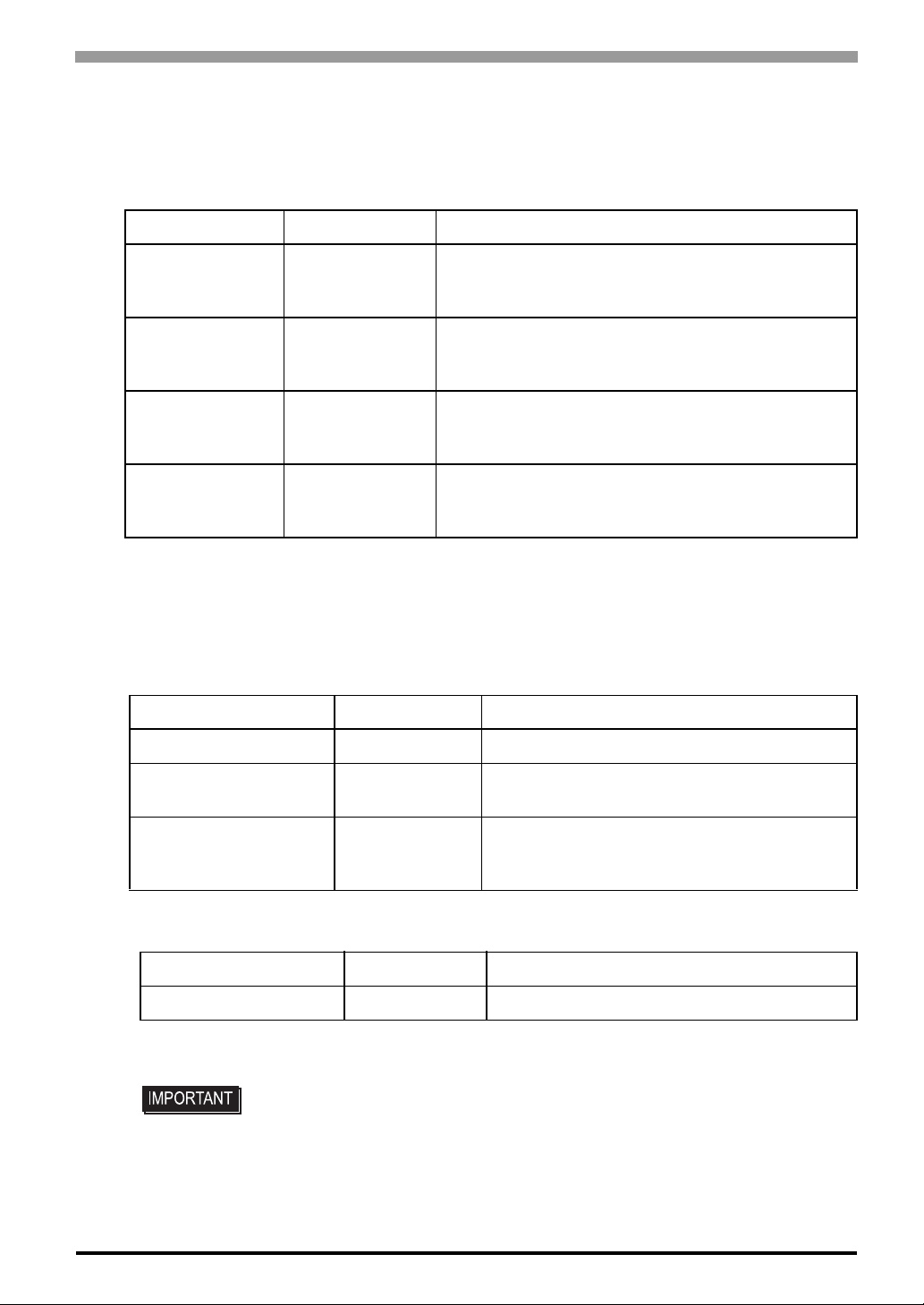
All optional items listed below are products of Digital Electronics Corporation.
Cables
Product Name Model No. Description
RS-232C Cable FP61V-IS00-O
USB Cable FP-US00
Analog RGB Cable FP-CV02-45
Chapter 1 Introduction
Serial interface cable (5m) used for touch panel data
transmission between the host and the FP. This is a
straight Dsub9 pin female cable.
USB interface cable (5m) used for touch panel data
transmission between the host and the FP. The cable
type is A-B.
Analog RGB interface cable (4.5m) when image signal
is output to the FP from the host. VGA specifications
(Dsub15 pin male). (4.5m)
DVI-D Cable
*1 The FP-DV01-100 can be used only when connected to a PS-2000B unit. When using
the FP-DV01-100, be sure to turn the PS-2000B’s internal dipswitch 4 ON.
(When using the FP-DV01-50, turn this switch OFF.)
Maintenance Parts
Product Name Model No. Description
Installation Fasteners CA3-ATFALL-01 Metal installation fasteners.
Rubber Gasket CA7-WPG19-01
Screen Protection Sheet CA7-DFS19-01
FP-DV01-50
FP-DV01-100
*1
Digital Visual Interface cable used to send the image
signal from the host to the FP. XGA specifications (DVID 24-pin male). (5 m or 10 m)
Replacement rubber gasket, used when installing
the FP. Same as the FP's original gasket.
Disposable and dirt resistant sheet for the FP's
screen. The FP's touch panel can be used with
this cover sheet attached. (5 sheets/set)
Related Software
Product Name Model No. Description
Mouse Emulator
*1
UPDD Mouse Emulator software for the FP
*1 OS can be Windows NT®4.0 SP6A or higher, Windows®2000 or Windows®XP.
• Visit our support site below and download the mouse emulation software (UPDD).
Digital Electronics Corporation’s support site - Otasuke Pro!
http://www.pro-face.com/otasuke/
1-3
Page 21

FP-3900T Series User Manual
MEMO
1-4
Page 22

2 Specifications
1. General Specifications
2. Functional Specifications
3. Interface Specifications
4. Cable Diagrams
5. Names and Functions
6. Dimensions
This chapter describes the general, functional and interface spe ci fications of the FP as well as its part names
and dimensions.
2-1
Page 23
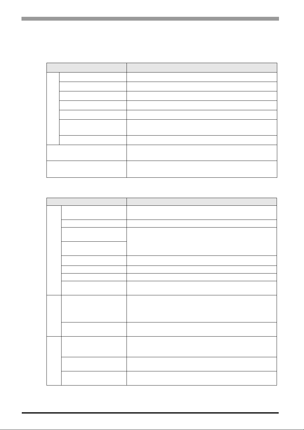
FP-3900T Series User Manual
2.1 General Specifications
2.1.1 Electrical specifications
Items Specifications
Rated Voltage AC100 to 240V
Allowable Voltage AC85 to 264V
Rated Frequency 50 / 60Hz
Rated Frequency Range 40 to 72 Hz
Allowable Voltage Drop 1 cycle or less (Volt age drop interval must be 1s or more)
Power Supply
Current Consumption
In-Rush Current 60A or less
Voltage Endurance
AC 100V 1.1A or less (TYP 0.75A)
AC 240V 0.7A or less (TYP 0.44A)
AC1500V 20mA for 1 minute
(between charging and FG terminals)
Insulation Resistance
2.1.2 Environmental specifications
Items Specifications
Surrounding Air
Temperature
Storage Temperature -20 to +60°C
Ambient Operating
Humidity
Ambient storage
Humidity
Physical
Air Purity (Dust) 0.1 mg/m
Pollution Degree For use in Pollution Degree 2 environment
Corrosive gas Free of corrosive gas
Atomospherical pressure
Resistance
Vibration Resistance
Mechanical
Impact Resistance
Noise Immunity
(via noise simulator)
Electrostatic
Discharge Immunity
Electrical
Surge Resistance
DC500V 10MΩ or more
(between charging and FG terminals)
0 to 50°C
(The panel face should not incline more than 30 °C)
10 to 90%RH
(Wet bulb temperature: 39°C or less - no condensation.)
3
or less (No electrically conductive dust is allowed)
800 to 1114hPa (Under above sea level 2000m)
JIS B 3502, IEC61131-2 compliant
5 to 9Hz Half amplitude 3.5mm
9 to150Hz Constant acceleration 9.8m/s
X, Y, Z each direction 10 cycles (100 minutes)
JIS B 3501, IEC61131-2 compliant
2
(147 m/s
6.0kV (EN61000-4-2 level3 compliant)
Normal Mode: 1 kV / Common Mode: 2kV
X, Y, Z each dire ction 3 times)
Noise Voltage: 1,500Vp-p
Pulse Duration: 1µs
Rise Time: 1ns
(IEC61000-4-5 level3 compliant)
2
2-2
Page 24

2.1.3 Structural specifications
Items Specifications
Grounding 100 Ω or less, or your country’s applicable standard.
Structure
External Dimensions W460mm [18.11in.] × H390mm [15.35in.] × D77.7mm [3.06in.]
Installation
Weight Approx. 10.0kg [22.0lb]
Cooling Method Natural air circulation
*1 The front face of the FP unit, installed in a solid panel, has been tested using conditions
equivalent to the standards shown in the specification. Even though the FP unit’s level of
resistance is equivalent to these standards, oils that should have no effect on the FP can possibly harm the unit. This can occur in areas where either vaporized oils are pres ent, or where
low viscosity cutting oils are allowed to adhere to the unit for long periods of time. If the
FP’s front face protection sheet becomes peeled off, these conditions can lead to the ingress
of oil into the FP and separate protection measures are suggested. Also, if non-approved oils
Chapter 2 Specifications
Rating*1: Equivalent to IP65f (Only not using Front USB)
figuration: Bult-in type
Installation method: Embedding
are present, it may cause deformation or corrosion of the front panel’s plastic cover. Therefore, prior to installing the FP be sure to confirm the type of conditions that will be present
in the FP’s operating environment.
If the installation gasket is used for a long period of time, or if the unit and its gasket are
removed from the panel, the original level of the protection cannot be guaranteed. T o maintain the original protection level, be sure to replace the installation gasket regularly.
2-3
Page 25
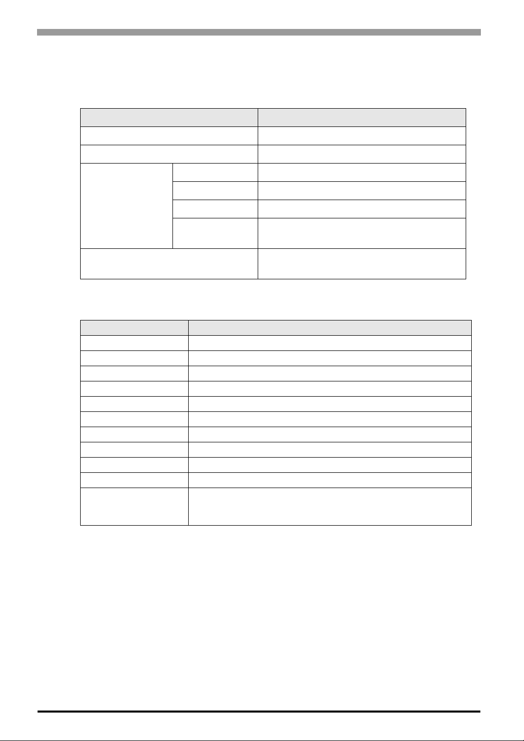
FP-3900T Series User Manual
2.2 Functional Specifications
2.2.1 Performance
Items Specifications
Graphics SXGA (1280 × 1024)
Display Unit 19 inch TFT SXGA
Resolution 1024 × 1024
Touch Panel I/F
Service Life 35,000,000 times or more
Type Resistive Film (Analog)
2.2.2 Display
Size 48cm(19 in.) (Meas. diagonally)
Type TFT Color LCD
Resolution 1280(H) × 1024(V) pixels (1pixel =R+G+B color dots)
Dot Pitch 0.294mm [0.01in.] × 0.294mm [0.01in.]
Display Colors 16,777,216 colors(R+G+B color 8 bits each)
Brightness Control Available
Contrast Control Available
Display Area H 376.32 mm [14.82 in.] × V301.056 mm [11.85 in.]
Display Modes 640×400, 640×480, 720×400, 800×600,1024×768,1280×1024
Backlight CCFL
Backlight Lifetime
Interface
Video I/F
Items Specifications
Backlight is not replaceable. (We offer replacement for backlights
by sendback method.)
50,000 hours at an ambient temperature of 25ºC
*1 50% decreased brightness indicates the backlight needs to be replaced. This value
Serial Interface (RS-232C)
USB Interface (Type-B connector)
Analog RGB Interface
DVI-D Interface
*1
2-4
is only for reference and not a guaranteed value.
Page 26
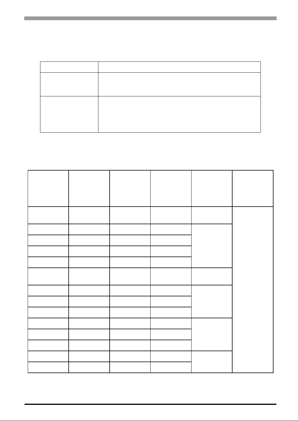
2.3 Interface Specifications
2.3.1 Analog RGB Interface
Input signal type Analog RGB
Chapter 2 Specifications
Input signal
characteristic
Setting via OSD
(On Screen Display)
Image signal: analog RGB
Synchronous signal: TTL level, negative polarity or positive polarity
Scanning type: non-interlaced
• CONTRAST
• H-POSITION
• H-size
• DIMMER (BACKLIGHT)
• ALL RESET (DEFAULT)
Display Area
The number of dots (pixels) displayed are as follows.
Size
640 × 400 31.469 70.000 25.175
640 × 480 31.469 59.992 25.175
640 × 480 35.000 66.670 30.240
640 × 480 37.861 72.810 31.500
H.Sync.
(kHz)
V.Sync.
(Hz)
Dot Clock
(MHz)
• BRIGHTNESS
• V-POSITION
• PHASE
• SHARPNESS
Screen
Resolution
Expansion
(H: Horizontal)
(V: Vertical)
× 2(H)
× 2.56(V)
× 2(H)
×2.13(V)
Display
Resolution
640 × 480 37.500 75.000 31.500
720 × 400
800 × 600 35.156 56.250 36.000
800 × 600 37.879 60.317 40.000
800 × 600 46.875 75.000 49.500
1024 × 768 48.363 60.004 65.000
1024 × 768 56.476 70.069 75.000
1024 × 768 60.023 75.029 78.750
1280 × 1024 63.981 60.000 108.000
1280 × 1024 79.976 75.000 134.999
*1
*1 When you use this resolution, set “ON“ for “720 × 400 Mode” in the OSD (On Screen Display)
system settings.
31.469 70.000 28.320
× 1.77(H)
× 2.56(V)
1280 × 1024
× 1.6(H)
× 1.7(V)
× 1.25(H)
× 1.33(V)
× 1.0
2-5
Page 27
FP-3900T Series User Manual
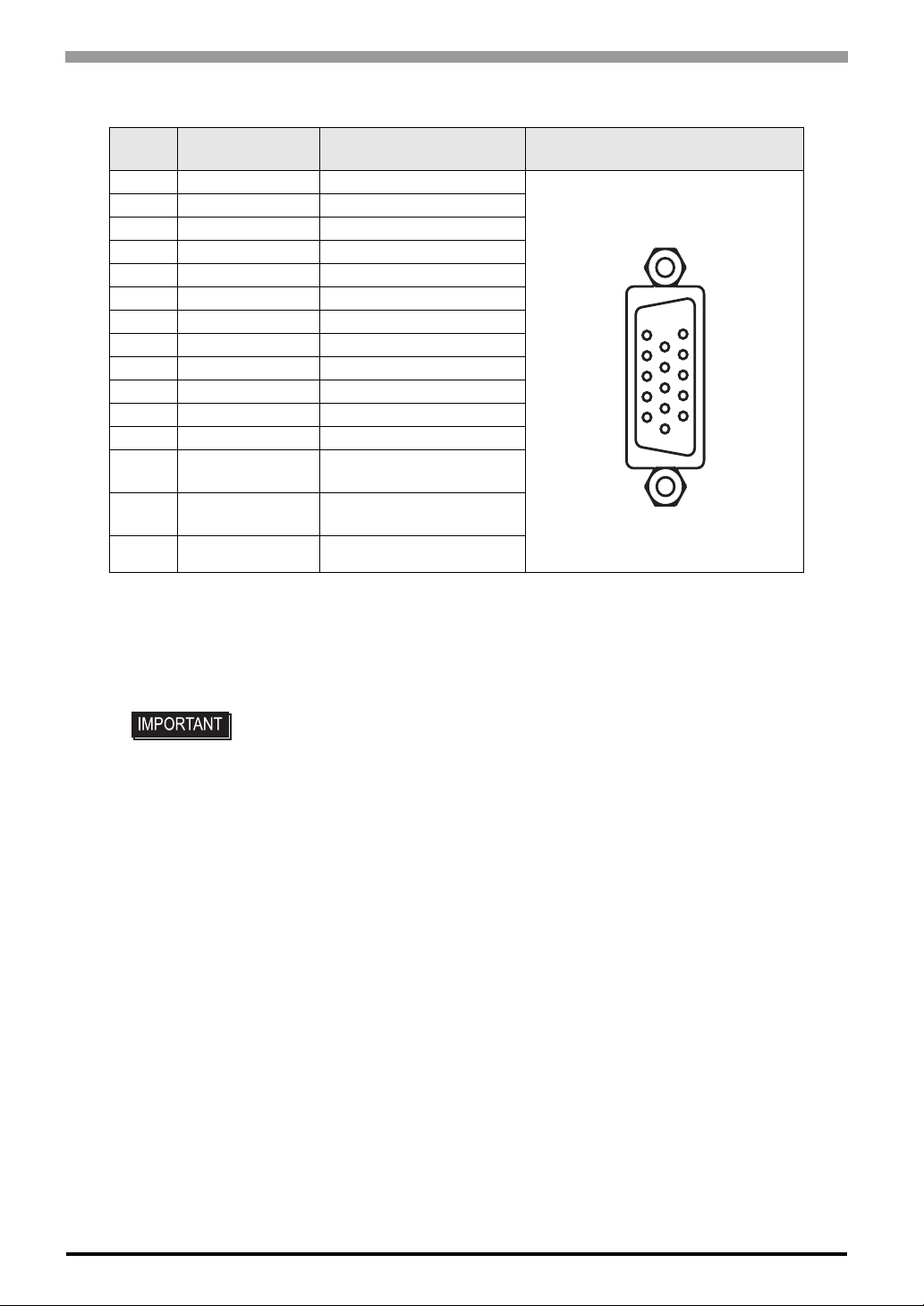
Analog RGB Interface Pin Assignments and Signal Names
Pin
No.
1 Analog R R signal input
2 Analog G G signal input
3 Analog B B signal input
4 Reserved NC (spare for input)
5 Digital grounding Digital signal GND
6 Return R R signal GND
7 Return G G signal GND
8 Return B B signal GND
9 Reserved NC (spare for input)
10 Digital grounding Digital signal GND
11 Reserved NC (spare for input)
12 DDC DATA DDC Data
13 H. SYNC
14 V. SYNC
15 DDC CLOCK DDC Clock
Signal Name Condition Pin Location
Horizontal synchronous
signal input
Vertical synchronous
signal input
15
5
111
Connector...........................:Mini Dsub 15pin male
Connector set screw...........:Inch type (4-40)
Cable........................ ..........:RGB cable manufactured by Pro-face
(FP CV02-45 <4.5m>)(VGA standard)
• If a cable other than the specified RGB cable is used, product performance cannot be guaranteed due to the possibility of noise interfering with the FP unit’s
operation.
2-6
Page 28
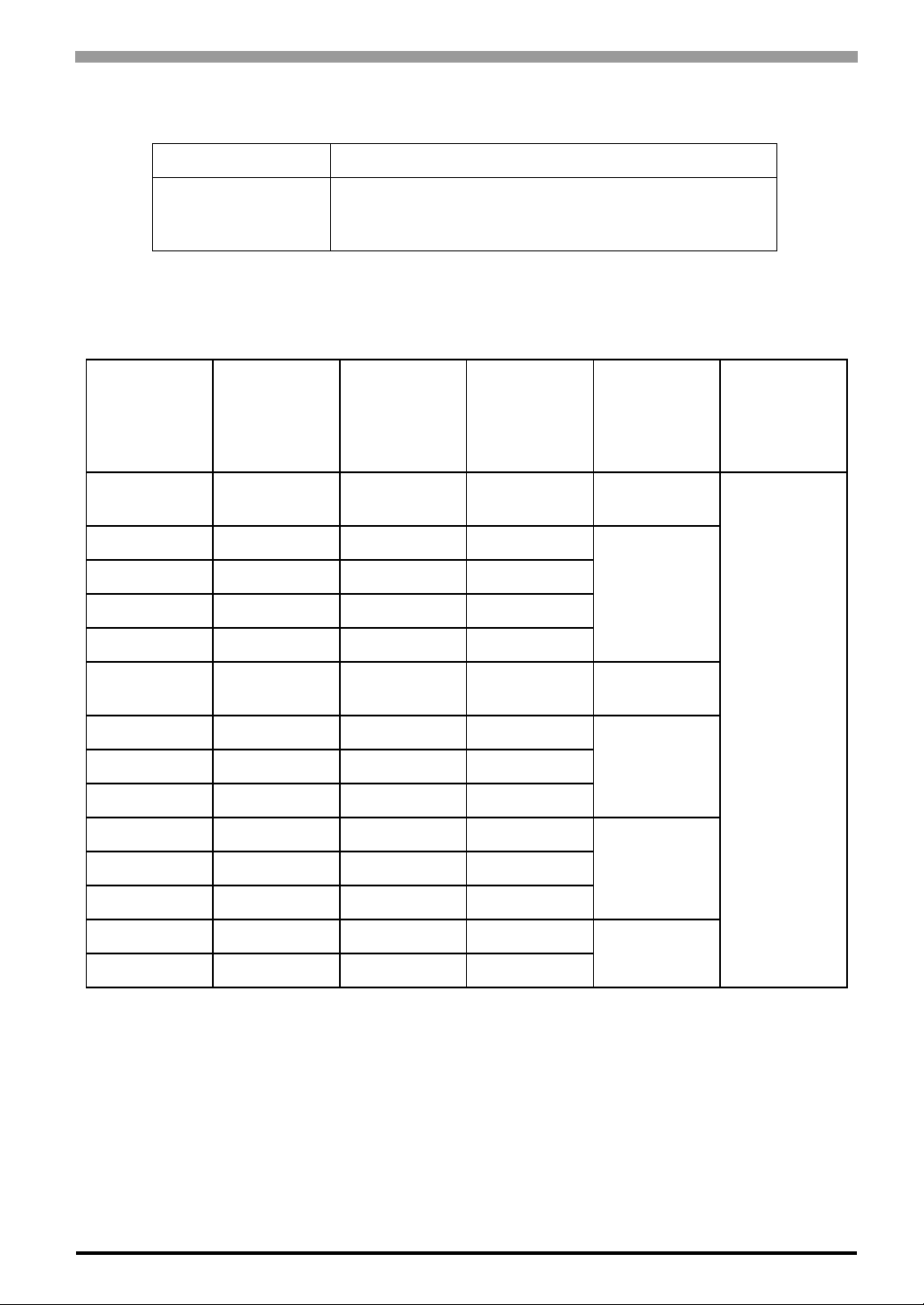
2.3.2 DVI-D Interface
Input signal type DVI-D
Chapter 2 Specifications
Setting by OSD
(On Screen Display)
• CONTRAST
• SHARPNESS
• ALL RESET (DEFAULT)
DIsplay Area
The number of dots (pixels) displayed are as follows: .
Size
640 × 400 31.469 70.000 25.175
640 × 480 31.469 59.992 25.175
640 × 480 35.000 66.670 30.240
640 × 480 37.861 72.810 31.500
640 × 480 37.500 75.000 31.500
720 × 400
800 × 600 35.156 56.250 36.000
800 × 600 37.879 60.317 40.000
800 × 600 46.875 75.000 49.500
*1
H.Sync.
(kHz)
31.469 70.000 28.320
V.Sync.
(Hz)
Dot Clock
(MHz)
• BRIGHTNESS
• DIMMER (BACKLIGHT)
Screen
Resolution
Expansion
(H: Horizontal)
(V: Vertical)
× 2(H)
× 2.56(V)
× 2(H)
×2.13(V)
× 1.77(H)
× 2.56(V)
× 1.6(H)
× 1.7(V)
Display
Resolution
1280 × 1024
1024 × 768 48.363 60.004 65.000
1024 × 768 56.476 70.069 75.000
1024 × 768 60.023 75.029 78.750
1280 × 1024 63.981 60.000 108.000
1280 × 1024 79.976 75.000 134.999
*1 When you use this resolution, set “ON“ for “720 × 400 Mode” in the OSD (On Screen Display)
system settings.
× 1.25(H)
× 1.33(V)
× 1.0
2-7
Page 29
FP-3900T Series User Manual
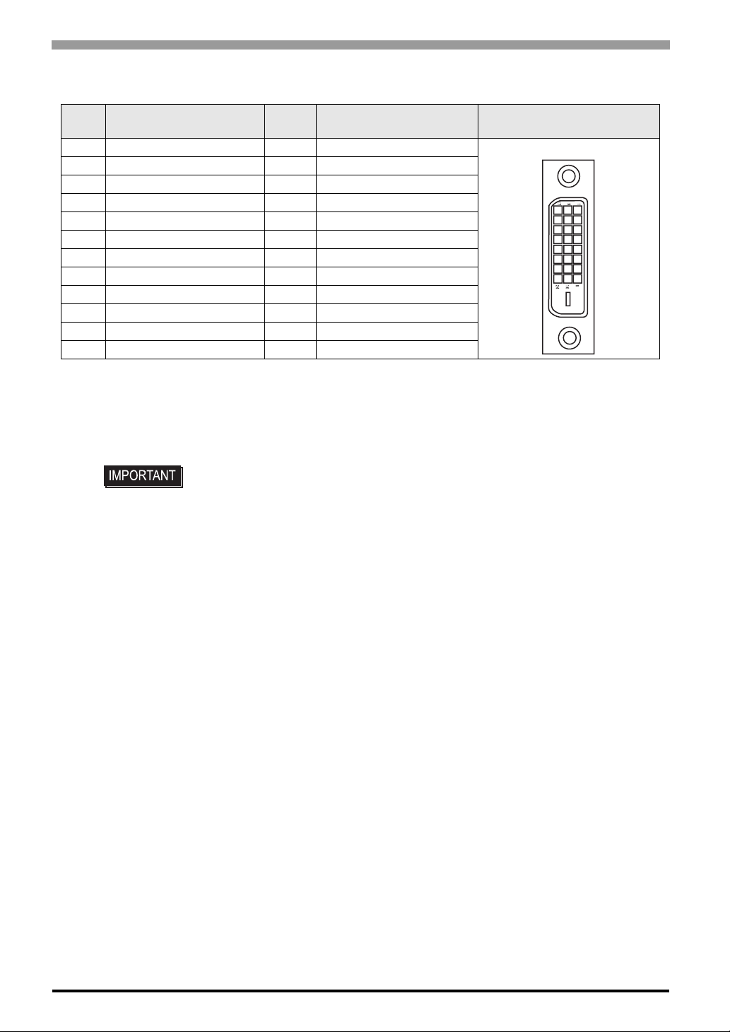
DVI-D Interface Pin Assignments and Signal Names
Pin
No.
1 TMDS DATA2- 13 NC
2 TMDS DATA2+ 14 NC
3 TMDS DATA2 SHIELD 15 GND
4 NC 16 Hot Plug Detect
5NC17TMDS DATA06 DDC Clock 18 TMDS DATA0+
7 DDC Data 19 TMDS DATA0 SHIELD
8NC20NC
9 TMDS DATA1- 21 NC
10 TMDS DATA1+ 22 TMDS CLOCK SHIELD
11 TMDS DATA1 SHIELD 23 TMDS CLOCK+
12 NC 24 TMDS CLOCK-
Signal Name
Connector................... .. ......DVI-D 24-pin male
Connector set screw........... Inch type (4-40)
Cable..................................DVI-D cable manufactured by Pro-face
• If a cable other than the specified DVI-D cable is used, product performance cannot be guaranteed due to the possibility of noise interfering with the FP unit's
operation.
Pin
No.
(FP-DV01-50 <5 m>, FP-DV01-100 <10 m>)
Signal Name Pin Location
17
24
1
8
• The FP-DV01-100 can be used only when connected to a PS-2000B unit. When
using the FP-DV01-100, be sure to turn the PS-2000B’s internal dipswitch 4 ON.
Display resolution which FP-DV01-100 can display is 1024 × 768 (XGA) only.
(When using the FP-DV01-50, turn this switch OFF).
2-8
Page 30
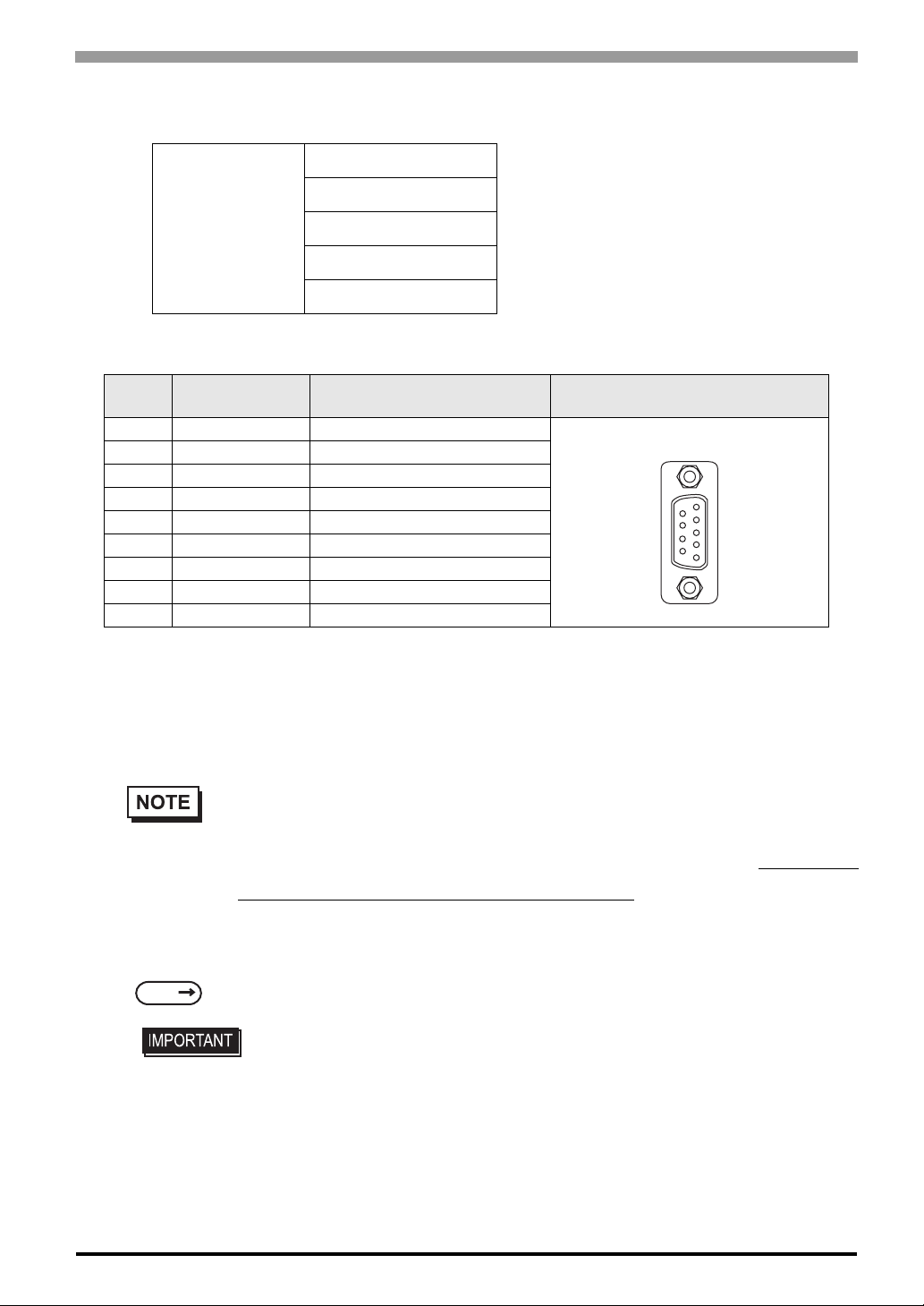
2.3.3 Serial Interface
Chapter 2 Specifications
Baud rate : 9600 bps
Data length : 8 bits
Serial Interface
Parity : none
Stop bit : 1
Flow control : None
RS-232C Interface Pin Assignments and Signal Names
Pin
No.
1 CD Carrier Detect
2 RD Receive Data (FP->Host)
3 SD Send Data (FP<-Host)
4 DTR Data Terminal Ready*1
5 GND Ground
6 DSR Data Set Ready *1
7 RS Request to Send (FP<-Host)
8 CS Clear to Send (FP->Host)
9 NC (Used internally)
Signal Name Condition Pin Location
*1
*1 CD, DTR, and DSR are connected together inside of the FP.
Connector...........................Dsub 9 pin female
Connector set screw...........Inch type (4-40)
6
9
1
5
Cable ..................................SIO cable manufactured by Pro-face
(FP61V-IS00-O)
• Concerning Signal Names
Signal names used for the serial interface on FP units are designed to match the pin order used on
most PC serial interfaces, so that a straight cable can be used to connect the two. Therefore, connect each pin's signal to the same signal name on the PC side.
For example, pin #2 ‘RD’ should be connected to the ‘RD’ input terminal on the PC’ s connector.
Refer to section “2.4 Cable Diagrams” for each signal’s direction.
SEE
2.4 Cable Diagrams (page2-12)
• If a cable other than the specified RS-232C cable is used, product performance
cannot be guaranteed due to the possibility of noise interfering with the FP unit's
operation.
2-9
Page 31
FP-3900T Series User Manual
2
1
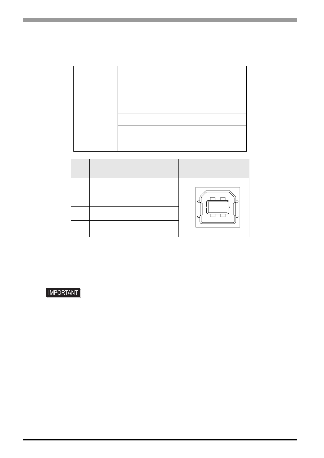
2.3.4 USB Interface (Up-stream port) USB Interface Pin Assignments and Signal Names
USB 2.0/1.1 compliant
• Low (1.5Mbps)
Supported speed
USB Interface
• Full (12 Mbps)
• Hi (480M bps)
Communication distance (Max): 5m
The USB Interface is supported by a host PC
equipped with Windows
®
2000(SP4) or later, or
Windows®XP(SP1) or later.
Pin
No.
Signal Name Condition Pin Location
1 USB1-5V +5VIN
2 USBD1(-) USB data(-)
3 USBD1(+) USB data(+)
4 GND Ground
Connector...........................USB 2.0 / USB 1.1 compliant
Connector set screw........... Type B connector
Cable..................................USB cabl e manufactured by Pro-face
(FP-US00)
43
2-10
• If a cable other than the specified USB cable is used, product performance
cannot be guaranteed due to the possibility of noise interfering with the FP unit’s
operation.
For using USB Interface, equal to or higher version of a Windows
®
2000(SP4) or Windows®XP(SP1) is
required.
Page 32
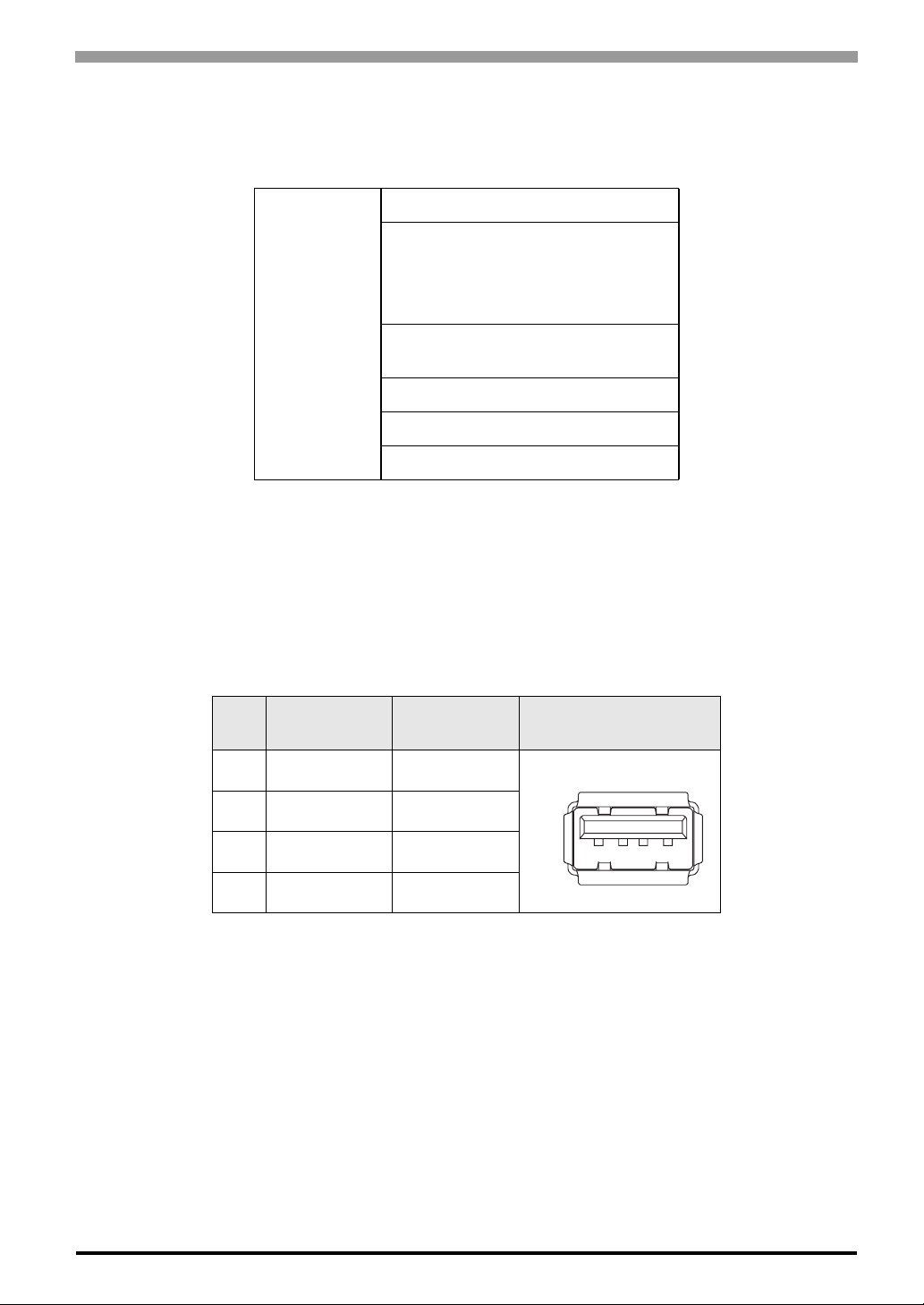
Chapter 2 Specifications
2.3.5 Front USB Interface (Down-stream port)(FP3710-T41-U model only) USB Interface Pin Assignments and Signal Names
USB 2.0/1.1 compliant
• Low (1.5Mbps)
Supported speed
USB Interface
Power supply voltage: 5 VDC ± 5%,
Output current: 500mA (max.)
Communication distance (Max): 5m
Connectable USB: 127
Connection phase: 6 phases*
*1 Those total numbers are based on how
many a host PC can connect USB, but the
numbers are not fixed, depending on the
condition of the PC’s connection. An FP is
equipped with a USB-HUB and it is connected to the touch panel controller.
Pin
No.
Signal Name Condition Pin Location
1 USB1-5V +5VIN
• Full (12 Mbps)
• Hi (480M bps)
*1
1
2 USBD1(-) USB data(-)
3 USBD1(+) USB data(+)
4 GND Ground
Connector...........................: USB 2.0 / USB 1.1 compliant
Connector set screw...........: Type A connector
1
4
2-11
Page 33

FP-3900T Series User Manual
2.4 Cable Diagrams
2.4.1 RGB Interface Cable Pin Connections (Option cable: VGA standard)
FP PC
1 Analog R Input 1 RED IN RED VIDEO 1 Output RED VIDEO 1
2 Analog G Input 2 GRN IN GRN VIDEO 2 Output GRN VIDEO 2
3 Analog B Input 3 BLU IN BLU VIDEO 3 Output BLU VIDEO 3
4 Reserved - 4 NC NC 4 - NC 4
5 Digital ground - 5 GND GROUND 5 - GROUND 5
6 Return R - 6 RED GND GROUND RED 6 - GROUND RED 6
7 Return G - 7 GRN GND GROUND GRN 7 - GROUND GRN 7
8 Return B - 8 BLU GND GROUND BLU 8 - GROUND BLU 8
9 Reserved - 9 NC NC 9 - NC 9
10 Digital ground - 10 GND GROUND 10 - GROUND 10
11 Reserved - 11 NC
MONITOR
SENSE(COLOR)
11 -
MONITOR
SENSE(COLOR)
11
12 DDC DATA
13 H.SYNC Input 13 HSYN HSYN 13 Output HSYN 13
14 V.SYNC Input 14 VSYN VSYN 14 Output VSYN 14
15 DDC CLOCK
FG FG - FG FG FG FG
Input/
Output
Input/
Output
12 SDA SDA 12
15 SCL SCL 15
Input/
Output
Input/
Output
SDA 12
SCL 15
Signals and signal names used with the FP and the RGB cable (optional cable) are the same as those used for
PCs. Also, the same pin is used on both sides of the optional cable so that you can connect the cable regardless
of the cable direction.
Inch is used for the pitch of the connector screw on the PC. For this reason, inch (4-40) is also used for the
pitch of the connector screw for the cable and the FP.
2-12
Page 34
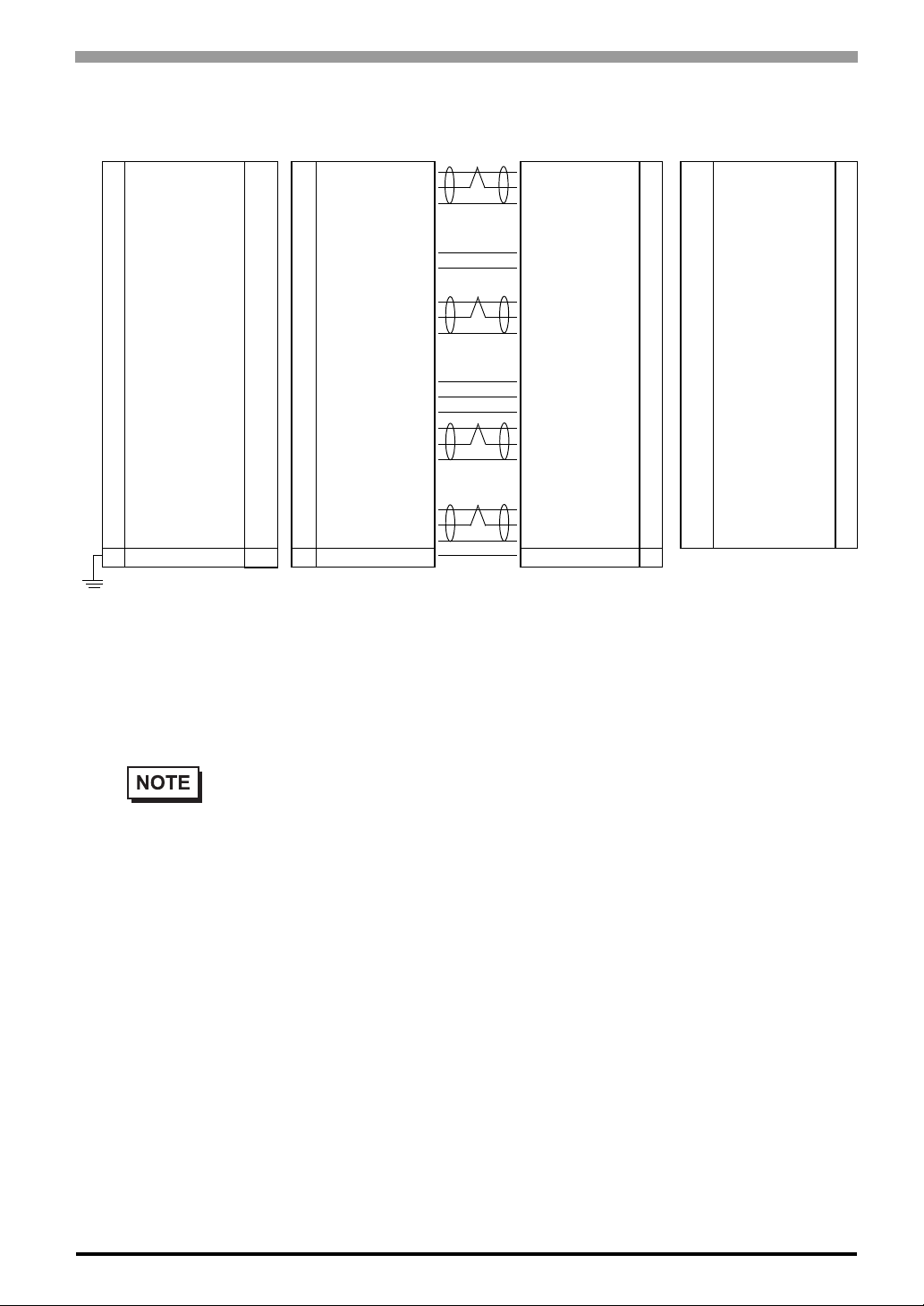
2.4.2 DVI-D Interface Cable Pin Connections (Option cable)
Chapter 2 Specifications
1 TMDS DATA2- Input 1 TMDS DATA2- TMDS DATA2- 1 Input TMDS DATA 2- 1
FP
2 TMDS DATA2+ Input 2 TMDS DATA2+ TMDS DATA2+ 2 Input TMDS DATA2+ 2
3 TMDS DATA2 SHIELD Input 3 TMDS DATA2 SHIELD TMDS DATA2 SHIELD 3 - TMDS DATA2 SHIELD 3
4NC - 4NC NC 4 - NC 4
5NC - 5NC NC 5 - NC 5
6 DDC Clock - 6 DDC Clock DDC Clock 6 - DDC Clock 6
7 DDC Data - 7 DDC Data DDC Data 7 - DDC Data 7
8NC - 8NC NC 8 - NC 8
9 TMDS DATA1- Input 9 TMDS DATA1- TMDS DATA1- 9 Input TMDS DATA1- 9
10 TMDS DATA1+ Input 10 TMDS DATA1+ TMDS DATA1+ 10 Input TMDS DATA1+ 10
11 TMDS DATA1 SHIELD - 11 TMDS DATA1 SHIELD TMDS DATA1 SHIELD 11 - TMDS DATA1 SHIELD 11
12 NC 12 NC NC 12 - NC 12
13 NC - 13 NC NC 13 - NC 13
14 NC 14 +5V Power +5V Power 14 - +5V Power 14
15 GND(+5V) 15 GND(+5V) GND(+5V) 15 - GND(+5V) 15
16 Hot Plug Detect 16 Hot Plug Detect Hot Plug Detect 16 - Hot Plug Detect 16
17 TMDS DATA0- Input 17 TMDS DATA0- TMDS DATA0- 17 Input TMDS DATA0- 17
18 TMDS DATA0+ Input 18 TMDS DATA0+ TMDS DATA0+ 18 Input TMDS DATA0+ 18
19 TMDS DATA0 SHIELD - 19 TMDS DATA0 SHIELD TMDS DATA0 SHIELD 19 - TMDS DATA0 SHIELD 19
20 NC - 20 NC NC 20 - NC 20
21 NC - 21 NC NC 21 - NC 21
22 TMDS CLOCK SHIELD - 22 TMDS CLOCK SHIELD TMDS CLOCK SHIELD 22 - TMDS CLOCK SHIELD 22
23 TMDS CLOCK+ Input 23 TMDS CLOCK+ TMDS CLOCK+ 23 Input TMDS CLOCK+ 23
24 TMDS CLOCK- Input 24 TMDS CLOCK- TMDS CLOCK- 24 Input TMDS CLOCK- 24
FG FG - FG FG FG FG
PC
Signals and signal names used with the FP and the DVI-D cable (optional cable) are the same as those used
for PCs. Also, the same pin is used on both sides of the optional cable so that you can connect the cable
regardless of the cable direction.
Inch is used for the pitch of the connector screw on the PC. For this reason, inch (4-40) is also used for the
pitch of the connector screw for the cable and the FP.
• The FP-DV01-100 cable’s 6, 7, 14 and 15 pins are not connected.
2-13
Page 35
FP-3900T Series User Manual
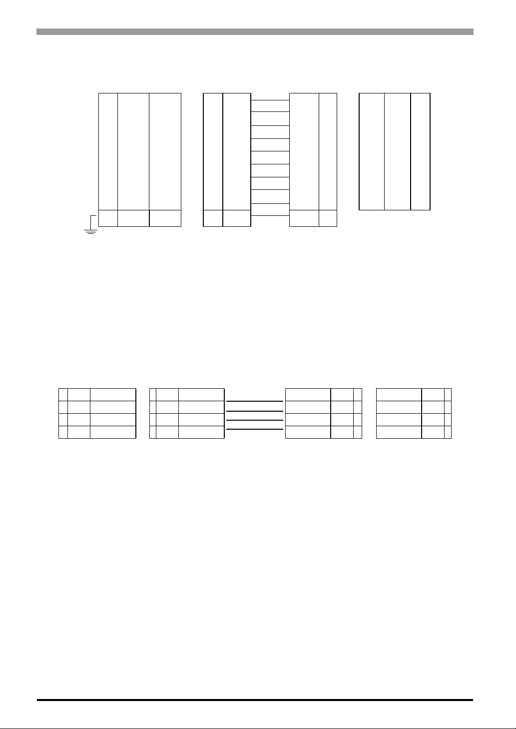
2.4.3 SIO Interface Cable Pin Connections
FP SIO cable PC
1 CD Output 1 CD CD 1 Input CD 1
2 RD Output 2 RD RD 2 Input RD 2
3 SD Input 3 SD SD 3 Output SD 3
4 DTR Input 4 DTR DTR 4 Output DTR 4
5 GND - 5 GND GND 5 - GND 5
6 DSR Output 6 DSR DSR 6 Input DSR 6
7 RS Input 7 RS RS 7 Output RS 7
8 CS Output 8 CS CS 8 Input CS 8
9NC - 9NC RI9 InputRI9
FG FG - FG FG FG FG
Signals and signal names used with the FP and the SIO cable (optional cable) are the same as those used for
PCs. Also, the same pin is used on both sides of the optional cable so that you can connect the cable regardless
of the cable direction.
Inch is used for the pitch of the connector screw on the PC. For this reason, inch (4-40) is also used for the
pitch of the connector screw for the cable and the FP.
2.4.4 USB Interface Cable Pin Connections
FP USB cable PC
1 +5VIN Intput 1 +5VIN Intput Output +5VIN 1 Output +5VIN 1
2 USB- Intput/Output 2 USB- Intput/Output Intput/Output USB- 2 Intput/Output USB- 2
3 USB+ Intput/Output 3 USB+ Intput/Output Intput/Output USB+ 3 Intput/Output USB+ 3
4 GND Intput/Output 4 GND Intput/Output Intput/Output GND 4 Intput/Output GND 4
2-14
Page 36
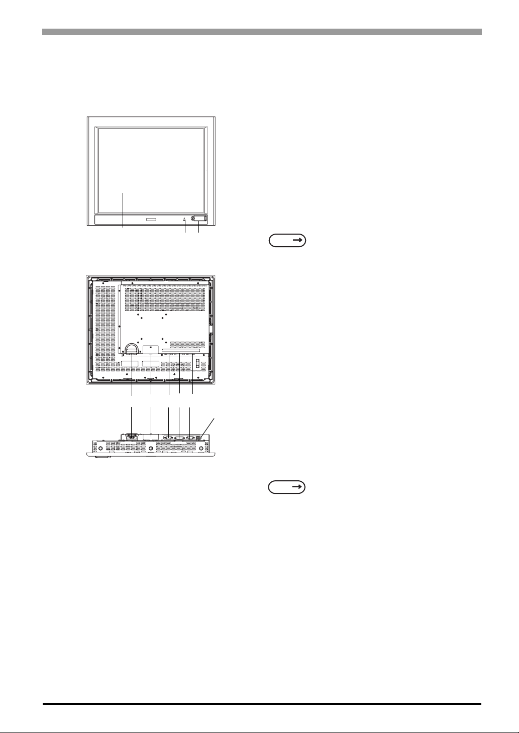
2.5 Names and Functions
)
A,B
Rear
I
Chapter 2 Specifications
A:TFT Color LCD
The display monitor for your host unit.
B:Touch Panel
Allows you to switch screens or write data to the host.
C:Power Connector (socket)
Provides the input and ground terminals for a power
cable.
D:Setting Switch
By opening the cover, the Dip switches and slide
switch are seen. Each switch can set a operation mode.
J
SEE
E:Analog RGB Connector
Connector for analog RGB interface
F:DVI-D Interface Connector
Connector for DVI-D interface
4.1 Operation Mode Setup (page4-2)
Bottom
C
DEFG
G: Serial Connector
Connector for Serial (RS-232C) interface. Used for
sending touch panel data to between the hosts.
H:USB Connector (Type B)
Connector for USB interface. Used for sending touch
H
panel data to the hosts, or used as an upstream port for
USB-HUB.
I: Front LED
Used to indicate the condition of the power supply, a
backlight burnout or image signal input.
SEE
J: Front USB Connector (Type A)(FP3900-T41-U only)
A downstream port for embedded USB-HUB in
conformity with USB2.0/1.1 standard, which is used
for connecting USB devices. Connect the USB
connector (H:USB connector) and Host PC for Front
USB connector use.
4.1.2 Status of Fr ont LED in Operation
Modes (page4-3
2-15
Page 37
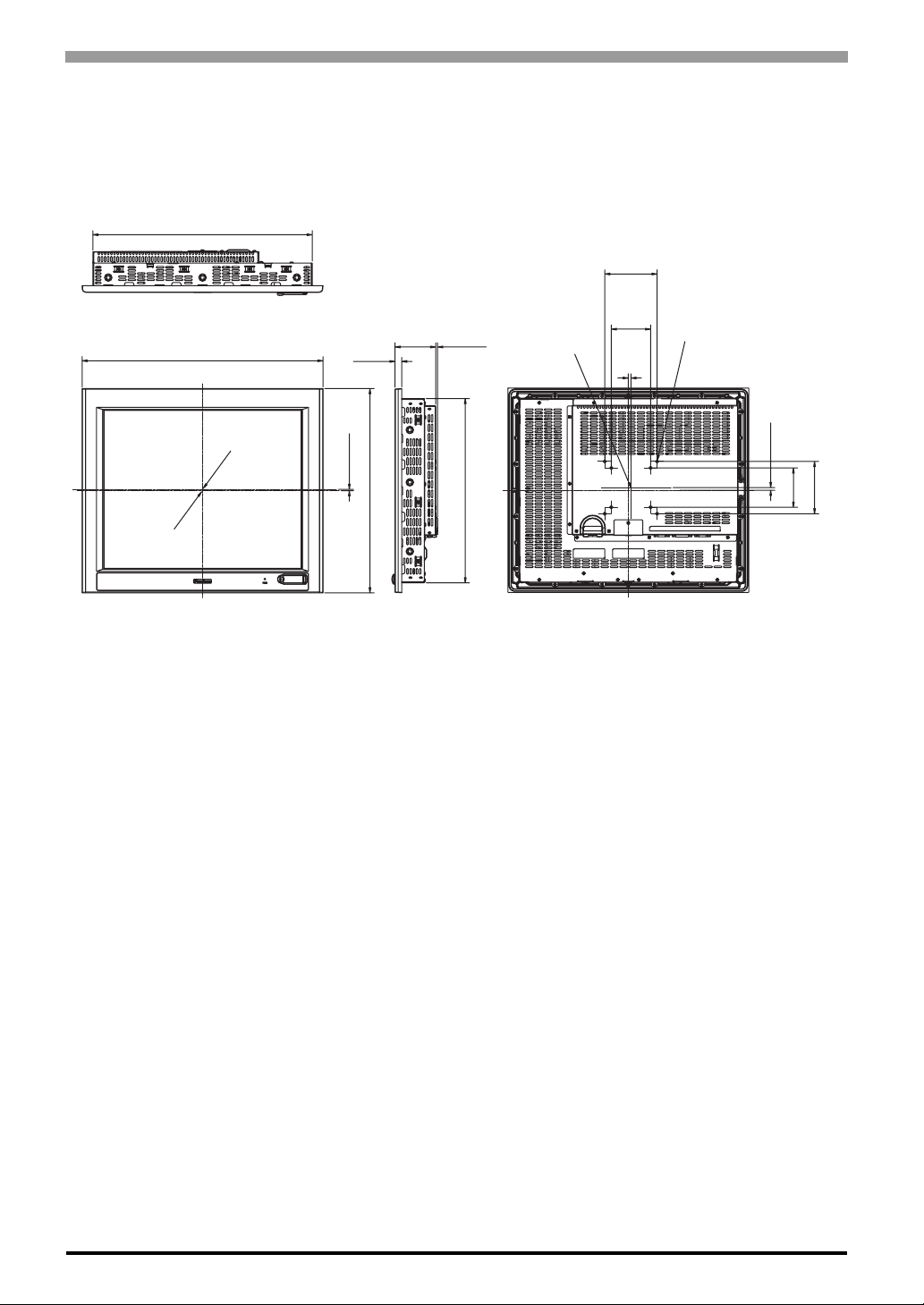
FP-3900T Series User Manual
2.6 Dimensions
2.6.1 External Dimensions
Unit: mm [in.]
419[16.50]
100[3.94]
Top
460[18.11]
center of display area
center of unit
Front
12.7
[0.50]
2.5[0.10]
390[15.35]
77.7
[3.06]
Side
3.5
[0.14]
352[13.86]
center of
VESA
75
[2.95]
5
[0.20]
Rear
8-M4
Effective Screw
Depth 7 [0.28]
5[0.20]
75 [2.95]
100 [3.94]
2-16
Page 38
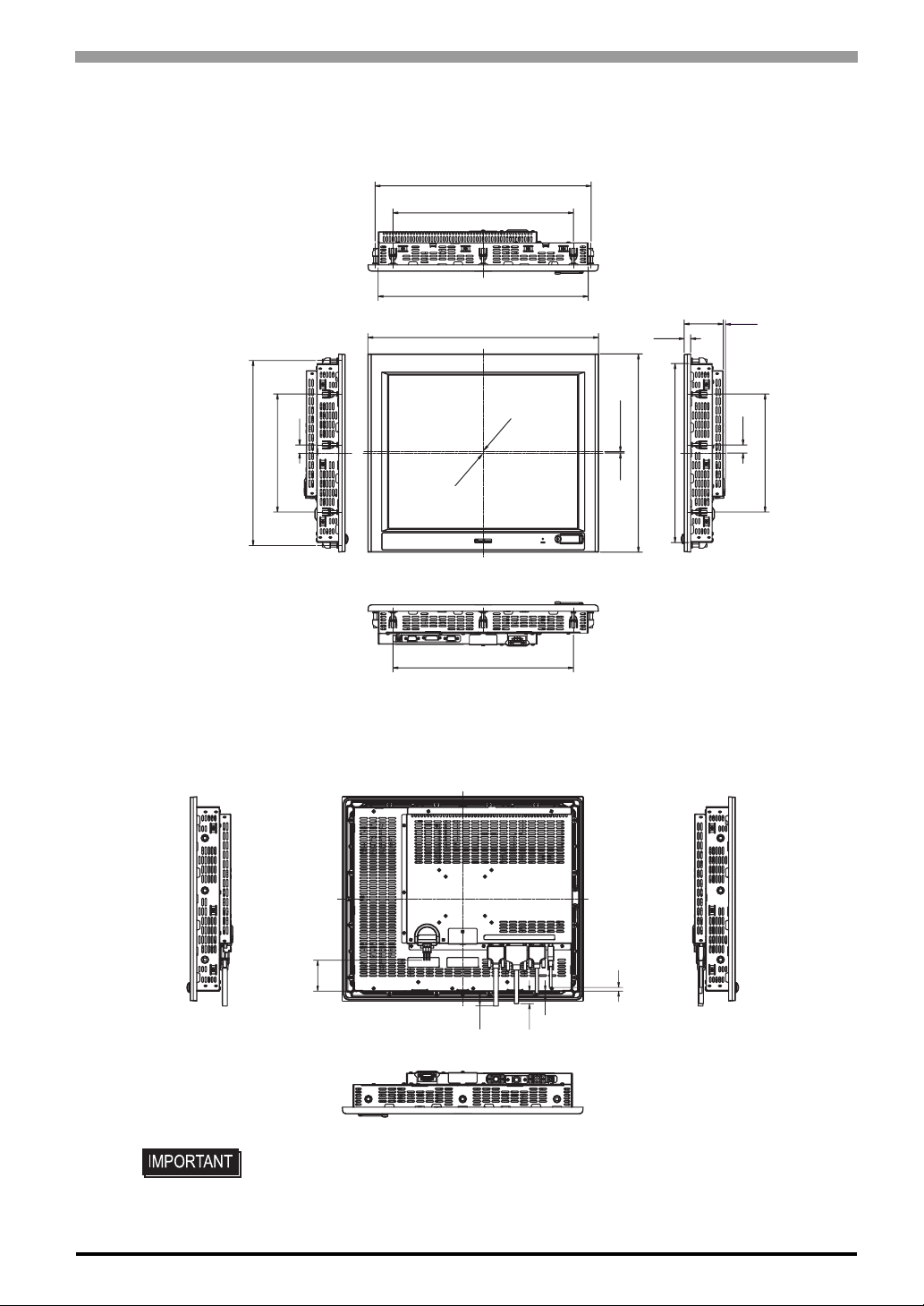
2.6.2 Dimensions with installation fasteners
Unit: mm [in.]
431[16.97]
360[14.17]
Chapter 2 Specifications
16[0.63]
232[9.13]
364[14.33]
Side
2.6.3 Dimensions with Cables
Unit: mm [in.]
419[16.50]
Top
460[18.11]
center of display area
center of unit
Front
360[14.17]
Bottom
12.7
[0.50]
2.5[0.10]
390[15.35]
77.7
[3.06]
352[13.86]
Side
3.5
[0.14]
16[0.63]
16[0.63]
232[9.13]
59[2.32]
Side
24[0.94]
4[0.16]
28[1.10]
• All the above values are designed in case of cable bending. The dimensions
given here are representative values depending on the type of connection cable
used. Therefore, they are all intended for reference only.
7[0.28]
Rear
Bottom
Side
2-17
Page 39
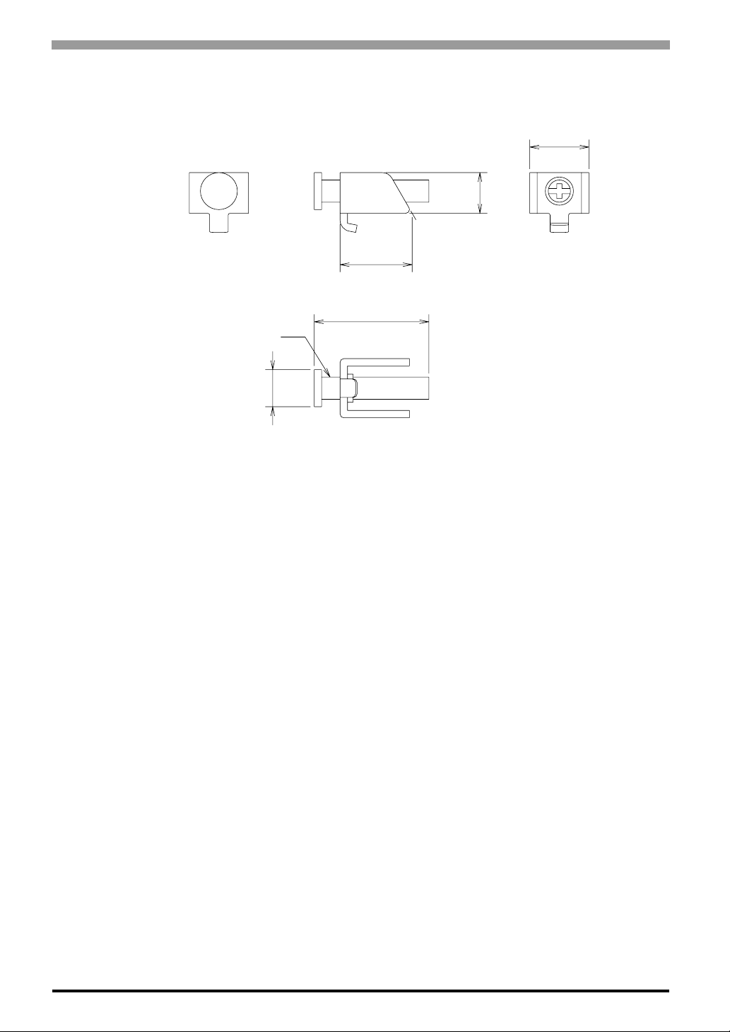
FP-3900T Series User Manual
2.6.4 Installation Fasteners
Unit: mm [in.]
16 [0.63]
11[0.43]
16.6 [0.65]
31 [1.22]
M6
∅10[0.39]
2-18
Page 40
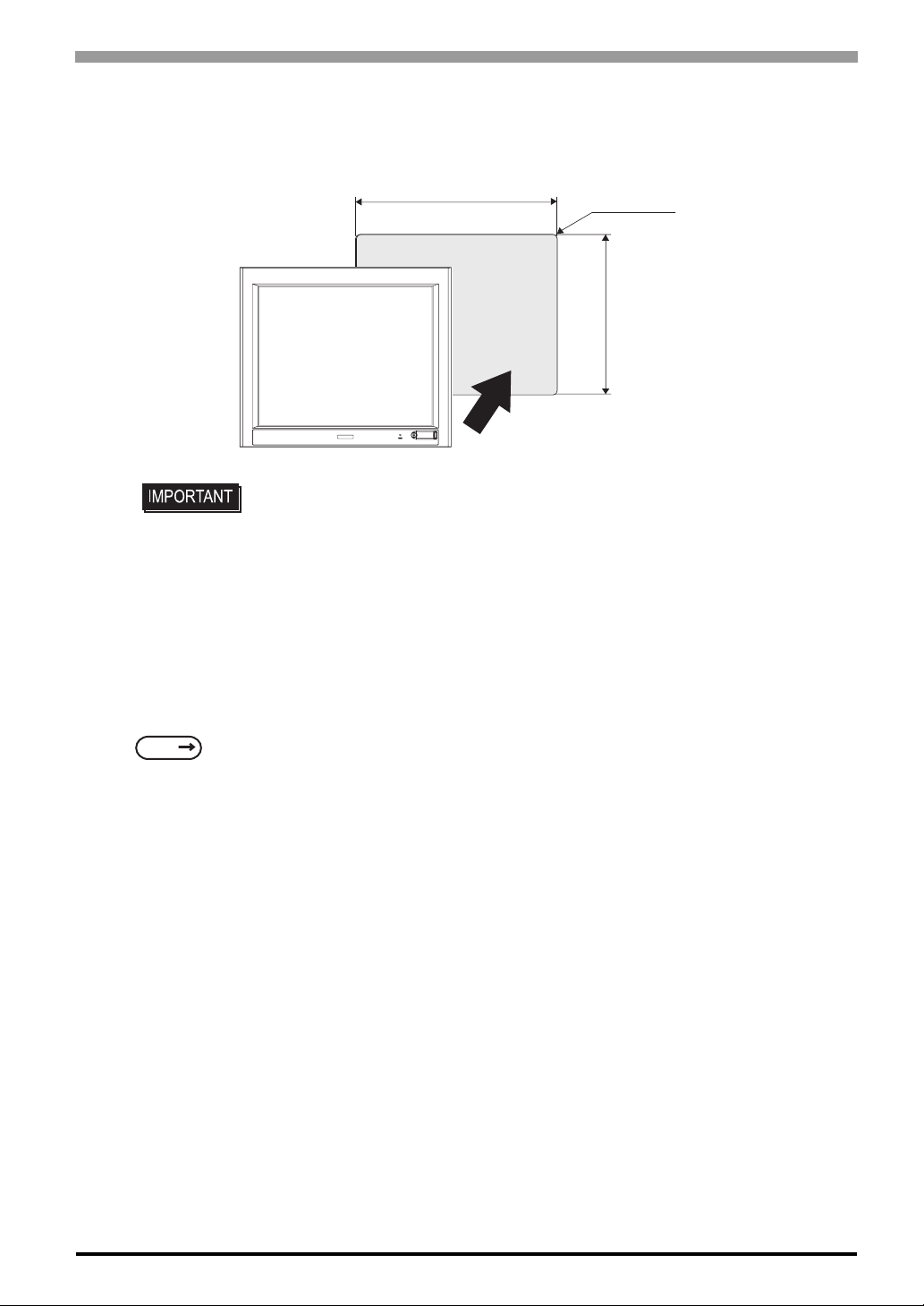
2.6.5 Panel Cut Dimensions
Unit: mm [in.]
Chapter 2 Specifications
419.5 [16.52 ]
FP
• Panel thickness should be between 1.6mm [0.06in.] and 10mm [0.39in.]. Decide
the panel's thickness based on the level of panel strength required.
• Check that the installation panel or cabinet's surface is flat, in good condition and
has no jagged edges.
• Create the correct sized opening required to install the FP, using the installation
dimensions given.
• If desired, metal reinforcing strips can be attached to the inside of the panel, near
+1.0
-0
+0.04
-0
Panel Cut
4-R3 [0.12] or less
-0
+0.04
-0
+1.0
352.5 [13.88 ]
SEE
the Panel Cut, to increase the panel's strength.
2.1.3 Structural specifications (page2-3)
2-19
Page 41

MEMO
20
Page 42

3 Installation and
Wiring
1. Installation
2. Wiring
This chapter explains the installation method and the wiring method for the FP.
3-1
Page 43
FP-3900T Series User Manual
3.1 Installation
3.1.1 Installation Procedures
Follow the steps given below when installing the FP.
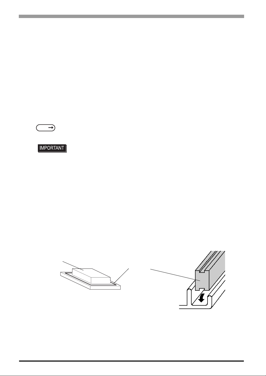
Check the Installation Gasket’s Seating
It is strongly recommended that you use the installation gasket, since it absorbs vibration in addition to
repelling water.
Place the FP on a level surface with the display panel facing downward. Check that the FP’s installation
gasket is seated securely into the gasket’s groove, which runs around the perimeter of the panel’s frame.
For details about installing the gasket, refer to
SEE
Rear face
7.1.2 Installation Gasket Replacement (page7-3)
• Before installing the FP into a cabinet or panel, check that the installation gasket
is securely attached to the unit.
• A gasket which has been used for a long period of time may have scratches or
dirt on it, and can lose much of its dust and drip resistance. Be sure to change the
gasket periodically (or when scratches or dirt become visible).
• Be sure to use gasket model CA7-WPG19-01.
• Be sure the gasket’s seam is not inserted into any of the uni t’s cor ners, only in th e
straight sections of the groove. Inserting it into a corner may lead to its eventually
tearing.
• To ensure the installation gasket’s maximum level of moisture resistance, be sure
the gasket’s seam is inserted as shown into the panel’s bottom face.
Gasket
3-2
Page 44
Chapter 3 Installation and Wiring
Creating a Panel Cut
Create the correct sized opening required to install the FP, using the installation dimensions given. The
installation gasket, installation fasteners and attachment screws are al l required when installing the FP
Decide the panel's thickness based on the level of panel strength required..
SEE
2.6.5 Panel Cut Dimensions (page2-19)
• Check that the installation panel or cabinet’s surface is flat, in good condition and has no jagged
edges. Also, if desired, metal reinforcing strips can be attached to the inside of the panel, near the
Panel Cut, to increase the panel’s strength.
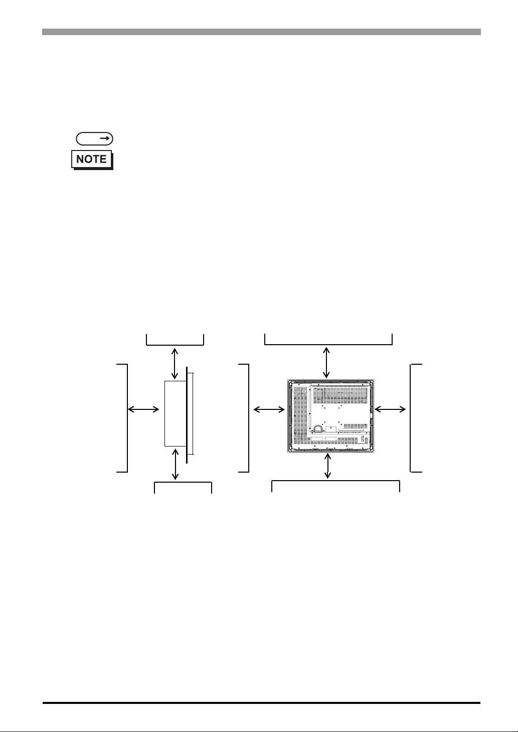
Installation Requirements
• For easier maintenance, operation, and improved ventilation, be sure to install the FP at least
100 mm [3.94 in.] away from adjacent structures and other equipment.
Unit: mm
[in.]
100
[3.94]
100
[3.94]
Side View
100
[3.94]
Rear View
100
[3.94]
100
[3.94]
100
[3.94]
100
[3.94]
3-3
Page 45
FP-3900T Series User Manual
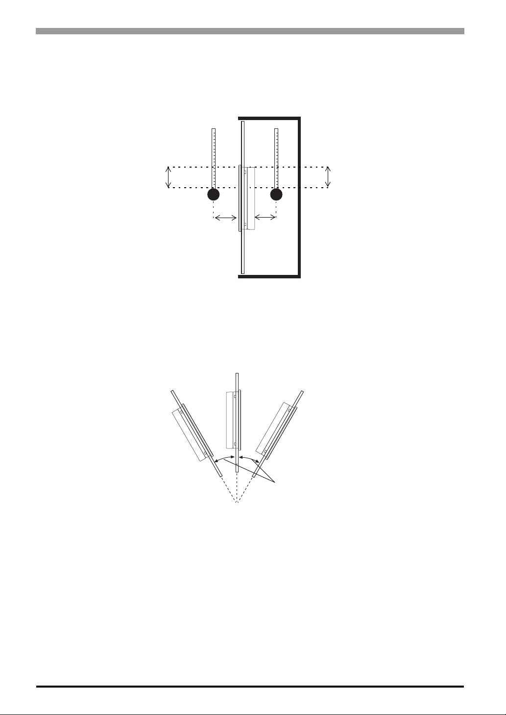
• Be sure that the ambient operating temperature and the surrounding operating humidity are within their
designated ranges. (When installing the FP in a cabinet or an enclosure, “Ambient operation temperature”
indicates both the panel face and cabinet or enclosure's internal temperature.).
Unit: mm
[in.]
o
100
[3.94]
C
100
[3.94]
30
[1.18]
Panel Face
30
[1.18]
Inside of the
enclosure
Ambient Operating Temperature: 0 to 50
Surrounding Operating Humidity:10 to 90%RH
• Be sure that heat from surrounding equipment does not cause the FP to exceed its standard operating temperature.
o
• When installing the FP in a slanted panel, the panel face should not incline more than 30
.
3-4
No more than 30 degrees of tilt
• When installing the FP in a slanted panel, and the panel face incline s more tha n 30o, the ambient tempera-
o
ture must not exceed 40
ating temperature is 40
C. You may need to use forced air cooling (fan, A/C) to ensure the ambient oper-
o
C or below.
Page 46
Installing the FP
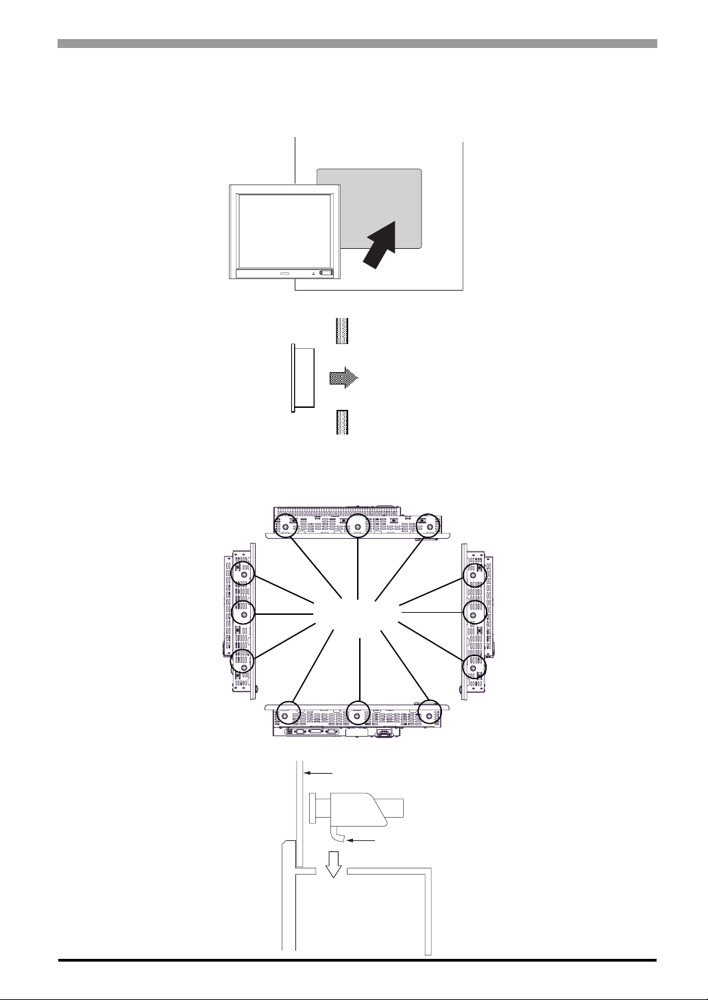
(1) Insert the FP into the panel cut, as shown here.
Panel
FP
Panel
Side
Chapter 3 Installation and Wiring
Panel Cut
(2) Insert the installation fasteners into the FP’ s inse rtion slots, at the left, right, top and bottom of the unit.
(total: 12 slots)
Top
Insertion Slots
Left side
Bottom
Installation panel
Hook
Right side
3-5
Page 47
FP-3900T Series User Manual
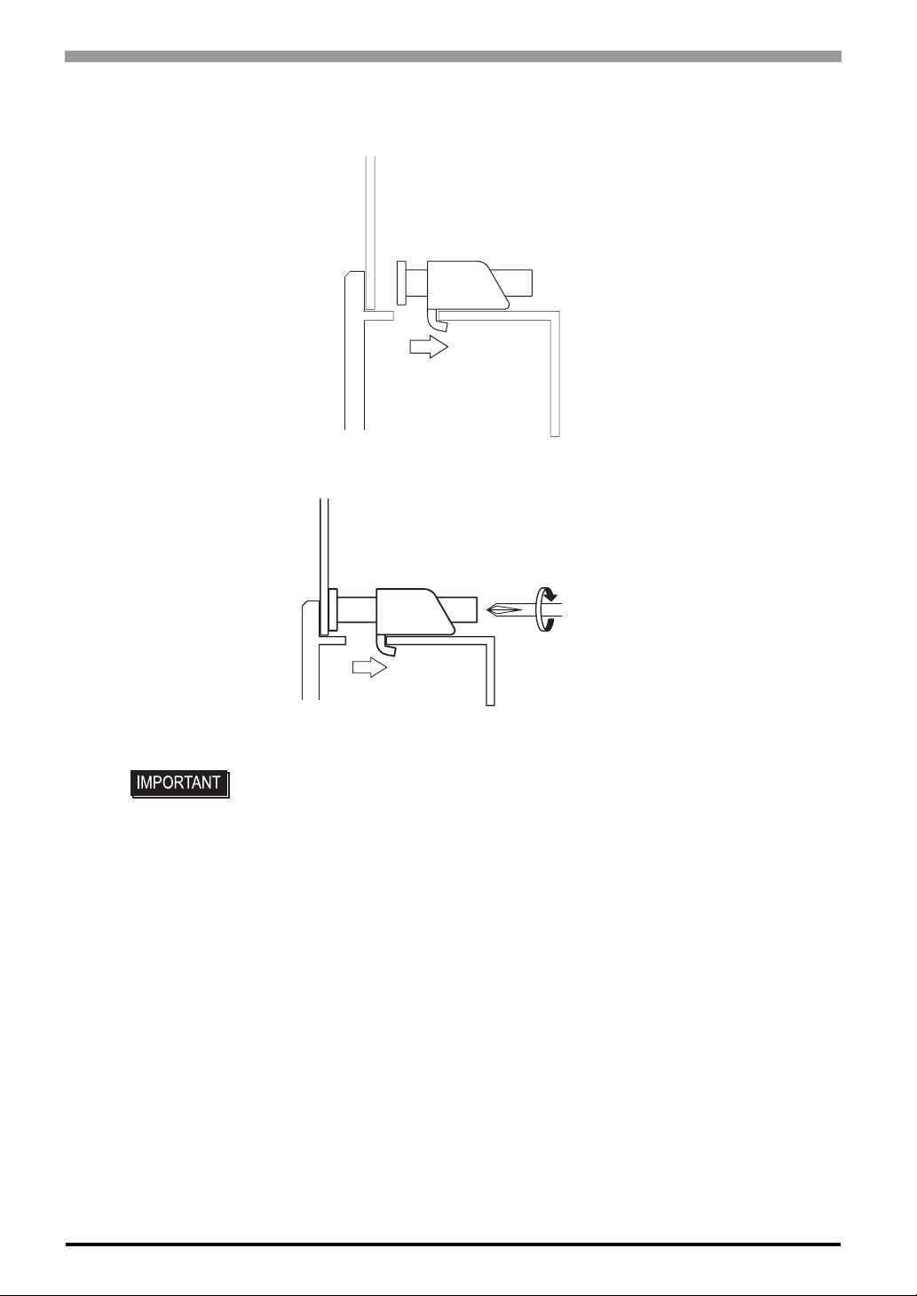
(3) Insert each of the fasteners as shown below. Be sure to pull the fastener back until it is flush with the
rear of the attachment hole.
(4) Use a Phillips screw driver to tighten each fastener screw and secure the FP in place.
3-6
• Do not use too much force, since it may damage the FP unit. A torque of only 0.8
N•m is sufficient to tighten these screws.
Page 48
3.2 Wiring
3.2.1 Connecting the Power Cord
To avoid an electric shock, when connecting the FP’s power cord terminals to the power
terminal block, confirm that the FP’s power supply is completely turned OFF , via a breaker,
or similar unit.
To avoid the dangers of fire, electric hazards and equipment damage, be sure to use only
the specified voltage when operating the FP.
Since there is no power switch on the FP unit, be sure to attach a breaker-type switch to its
power cord.
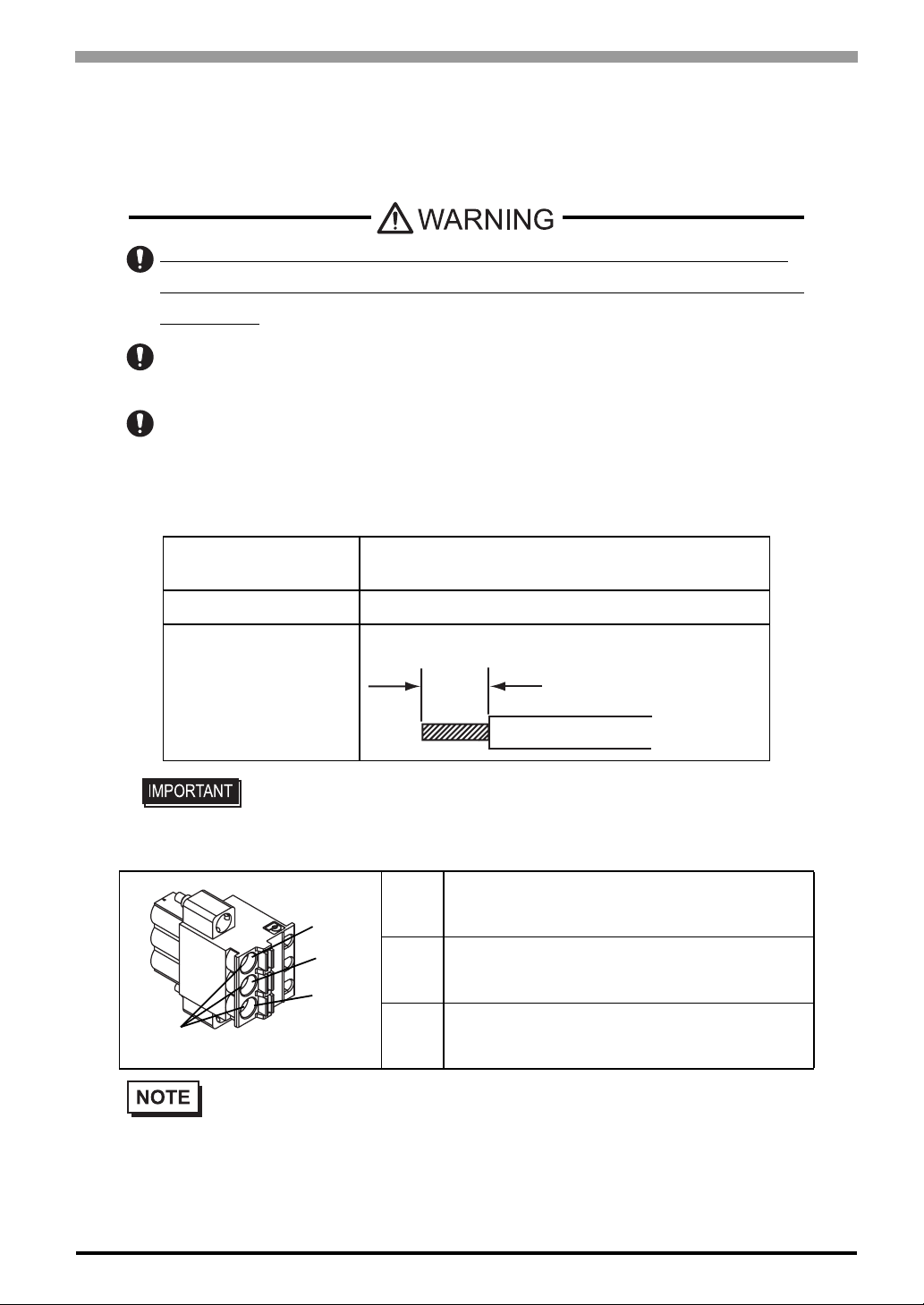
Power Cable specification
Use copper conductors only.
Power Cord Diameter
0.75mm
(18AWG to 12 AWG)
Chapter 3 Installation and Wiring
2
to 2.5mm2 [0.0009 to 0.0097inch2]
Conductor Type Simple or Twisted Wire
10mm [0.39in.]
Conductor Length
• If the Conductor’s end (individual) wires are not twisted correctly, the end wires
may either short against each other, or against an electrode.
Power connector specification
L AC Input Terminal-live line
L
N
FG
Power Cable Joint
• Kind of power cord is FKC 2,5/3-STF-5,08 which are Phoenix Contact*1 products.
N AC Input Terminal-neutral line
FG Ground Terminal connected to the FP chassis
*1 Please contact Phoenix Contact for the details.
3-7
Page 49
FP-3900T Series User Manual
Wiring
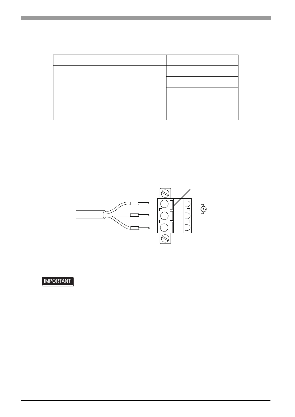
Use the following wiring for FP. Those are Phoenix Contact products.
Recommended Drivers SZS 0.6X3.5 (1205053)
AI 0.75-10GY(3201288)
Recommended stick end terminal
Crimp tool for recommended stick end terminal CRIMPFOX ZA 3 (1201882)
Connecting the Power Cord
When connecting the AC type power cord, be sure to follow the procedures given below.
(1) Confirm that the power cord is unplugged from the power supply.
(2) Push the Opening button by a small and flat screw driver to open the desired pin hole.
(3) Insert each pin te rmi n al in t o its ea ch hole. Release the Opening button to clamp the pin place.
AC power supply cord
AI 1-10RD(3200182)
AI 1.5-10BK(3200195)
AI 2.5-12BU(3200962)
Opening Button
L
N
FG
3-8
(4) After inserting all three pins, insert the Power Plug into the Power Connector at FP. Fix the plug with
two(2) minus screws.
• Confirm that all wires are connected correctly.
• The torque required to tighten these screws is 0.5 N•m - 0.6 N•m.
• To prevent the possibility of a terminal short, use a pin terminal that has an
insulating sleeve.
Page 50
3.2.2 The USB Cable Clamp
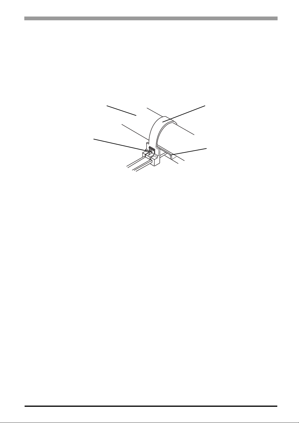
How to use the USB cable clamp
USB Cable Clamp Attachment Procedure
(1) Connect the USB cable to the connector.
(2) Insert the cable clamp into the cable clamp holder as shown in figure 1, and tighten the clamp until the
cable is secured in place.
Chapter 3 Installation and Wiring
USB Cable
Stopper
Figure 1
USB Cable Clamp Removal Procedure
(1) Push in the cable clamp’s stopper until the cable clamp is unlocked, then remove the clamp.
(2) Disconnect the USB cable.
USB cable clamp
USB cable clamp holder
3-9
Page 51
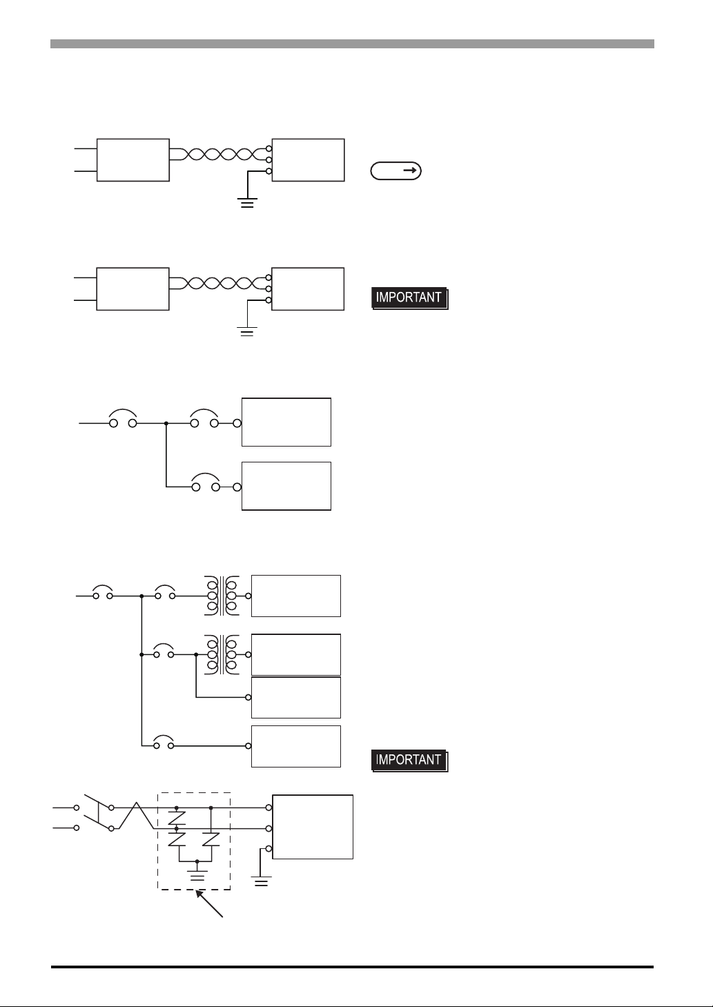
FP-3900T Series User Manual
3.2.3 Connecting the Power Supply
Constant
Voltage
Transformer
Insulating
Transformer
Main
Power
Twisted-pair cord
Twisted-pair cord
FP
Power
Input/Output
Power
FP Unit
FG
FP Unit
FG
FP Unit
Input/Output
Unit
• If the power supply voltage exceeds the FP unit’s specified range, connect a constant voltage transformer .
SEE
• For between the line and ground or between the lines,
select a power supply that is low in noise. If there is an
excess amount of noise, connect an insulating transformer.
• When supplying power to the FP unit, please separate
the input/output and operation unit lines, as shown.
• To increase the noise resistance quality of the power
cable, simply twist each power wire before attaching
the Ring Terminal.
• The power supply cable must not be bundled or positioned close to main circuit lines (high voltage, high
2 Specifications (page2-1)
• Use the constant voltage
transformer and the insulating
transformer with capacities of the
rated value or more.
Main
PowerFP Power
Input/Output
Power
T1
T2
Main Circuit Power
Motor
E1
lightningsurge
absorber
FP Unit
Input/Output
Unit
Input/Output
Unit
Operation
Unit
FP Unit
FG
E2
current), or input/output signal lines.
• Connect a lightning surge absorber, as shown in the
diagram, to deal with power surges.
• To avoid excess noise, make the power cable as short
as possible.
• The temperature rating of field installed conductors:
o
C only.
75
• Be sure to ground the surge
absorber (E1) separately from the
FP unit (E2).
• Select a surge absorber that has a
maximum circuit voltage greater
than the power supply’s peak
voltage.
3-10
Page 52
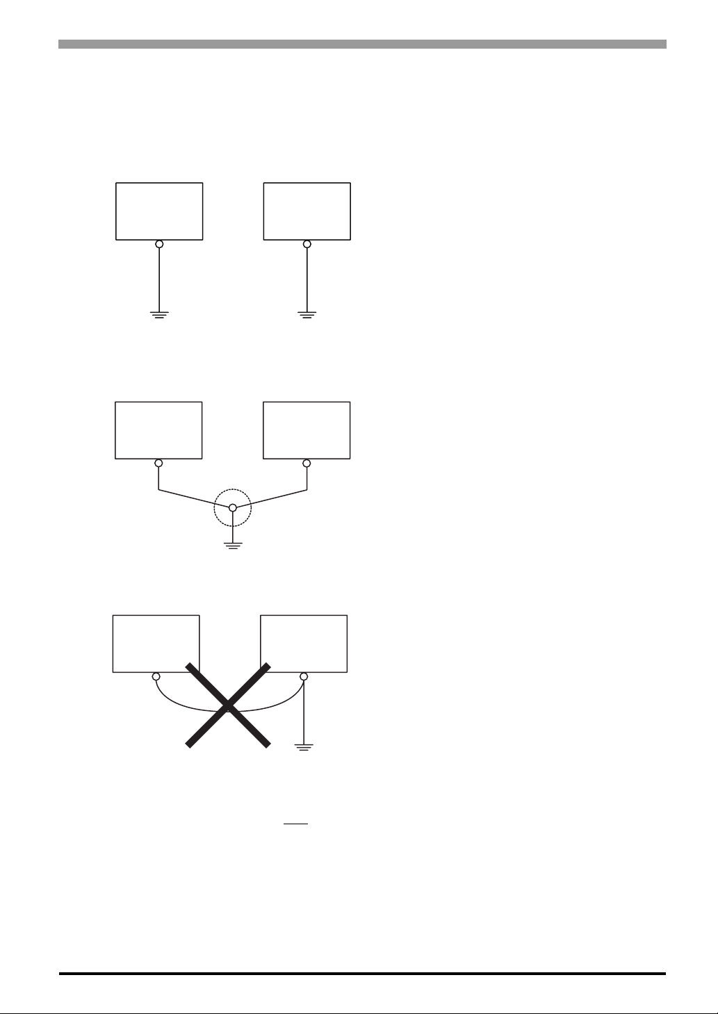
3.2.4 Precautions: Grounding
Chapter 3 Installation and Wiring
(a) Exclusive grounding (BEST)
FP Unit
(b) Common grounding (OK)
FP Unit
Other
Equipment
Other
Equipment
• Connect the FP’s FG terminal to an exclusive ground.
[diagram (a) - Grounding resistance of under 100Ω.]
• If exclusive grounding is not possible, use a common
connection point. [diagram (b)]
• The grounding wire should have a cross sectional area
2
greater than 2mm
to the FP unit as possible, and make the wire as short as
possible. When using a long grounding wire, replace
the thin wire with a thicker wire placed in a duct.
. Make the connection point as close
(c) Common grounding (BAD)
FP Unit
Other
Equipment
3.2.5 Precautions: Input/Output Signal Lines
• Input an d output signal lines must be separated from operating circuit power cables.
• If this is not possible, use a shielded cable and connect the shield to the FP chassis.
• If this equipment does not function properly when
grounded, disconnect the ground wire from the FG terminal.
3-11
Page 53

FP-3900 Series User Manual
MEMO
3-12
Page 54

4 Setting up and
Adjusting the FP
unit
1. Operation Mode Setup
2. Screen Display Adjustment
This chapter describes the settings of the operation mode and the OSD.
4-1
Page 55
FP-3900T Series User Manual
4.1 Operation Mode Setup
4.1.1 Preset Settings and Adjustments for Dip Switch and Slide Switch
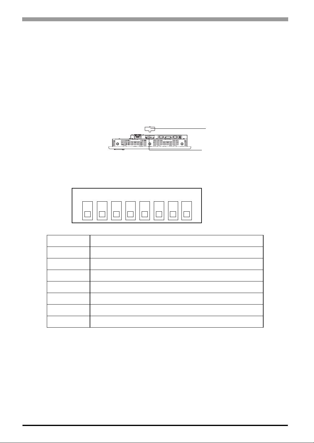
The Dip Switches and Slide Switch are located in the bottom of the FP unit. Loosen the screws of the cover
with a Phillips head screwdriver and then remove the cover. After setting the dip switches and slide switches,
reinstall the cover and screws with the screwdriver. The tightening torque for those screws is 0.5 ~ 0.6 N•m.
Only the settings when the power supply is turned on is effective to the Dip Switches and the Slide Switch.
After changing the settings of the Dip Switches and the Slide Switch, be sure to restart your FP unit.
Bottom
Cover
Dip Switches (SW1)
Slide Switch (SW2)
The factory default for the FP unit’s Dip Switches and Slide Switch are as follows.
SW1
1 2 3 4 5 6 7 8
ON
SW1-1 Reserved (Always OFF)
SW1-2 Display/Hide the OSD
SW1-3 Reserved (Always OFF)
SW1-4 Reserved (Always OFF)
SW1-5 Reserved (Always OFF)
SW1-6 Reserved (Always OFF)
SW1-7 Reserved (Always OFF)
SW1-8 Reserved (Always OFF)
•SW1-2
Dip Switch SW1-2 is used to display or hide the OSD.
To hide the OSD, set the switc h to ON. To display the OSD, set the switch to OFF.
4-2
The default setting is OFF. (OSD is displayed.)
Page 56
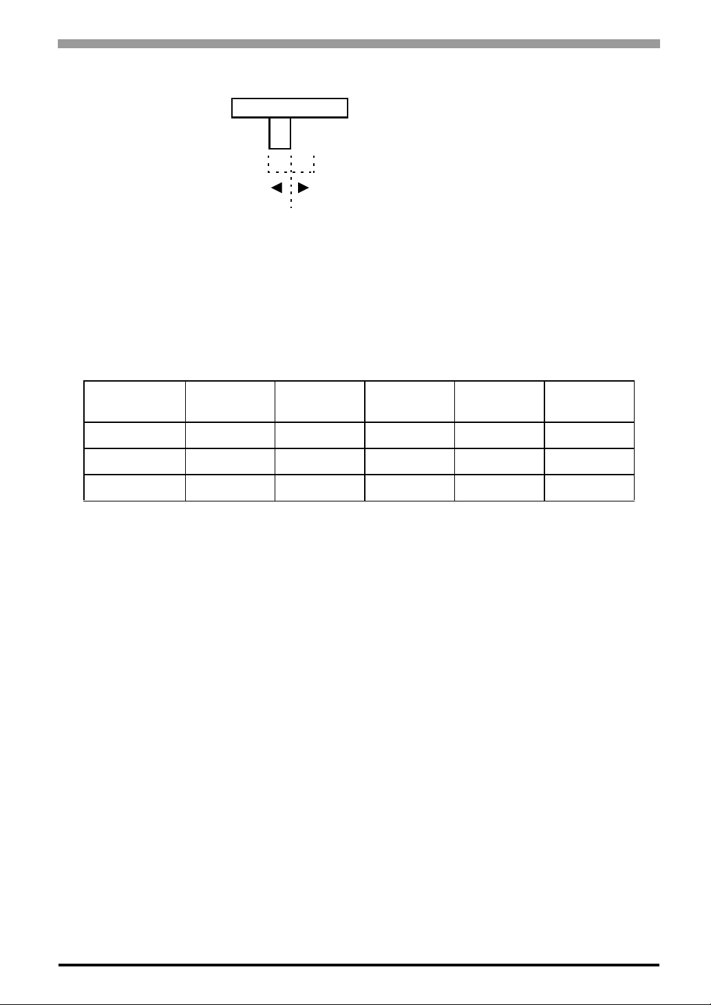
SW2
Chapter 4 Setting up and Adjusting the FP unit
232
• Slide Switch is used to switch the data input/output (command control) method on the touch panel
between USB and RS-232C.
The default setting is RS-232C.
USB
4.1.2 Status of Front LED in Operation Modes
LED OFF Green Orange
Panel Power OFF Power ON Power ON Power ON Power ON
Backlight - Normal Normal Burned-out Burned-out
Input of Image - Yes No Yes No
*1 Only while “No signal” is displayed.
Green/
Red Flash
Orange
*1
Flash
4-3
Page 57
FP-3900T Series User Manual
4.2 Screen Display Adjustment
4.2.1 Calibration of OSD Display Position
You can operate the FP screen menus via the touch panel, and adjust screen image display to a minute level.
The feature is called OSD (On Screen Display).
This section describes items and functions that can be set with OSD.
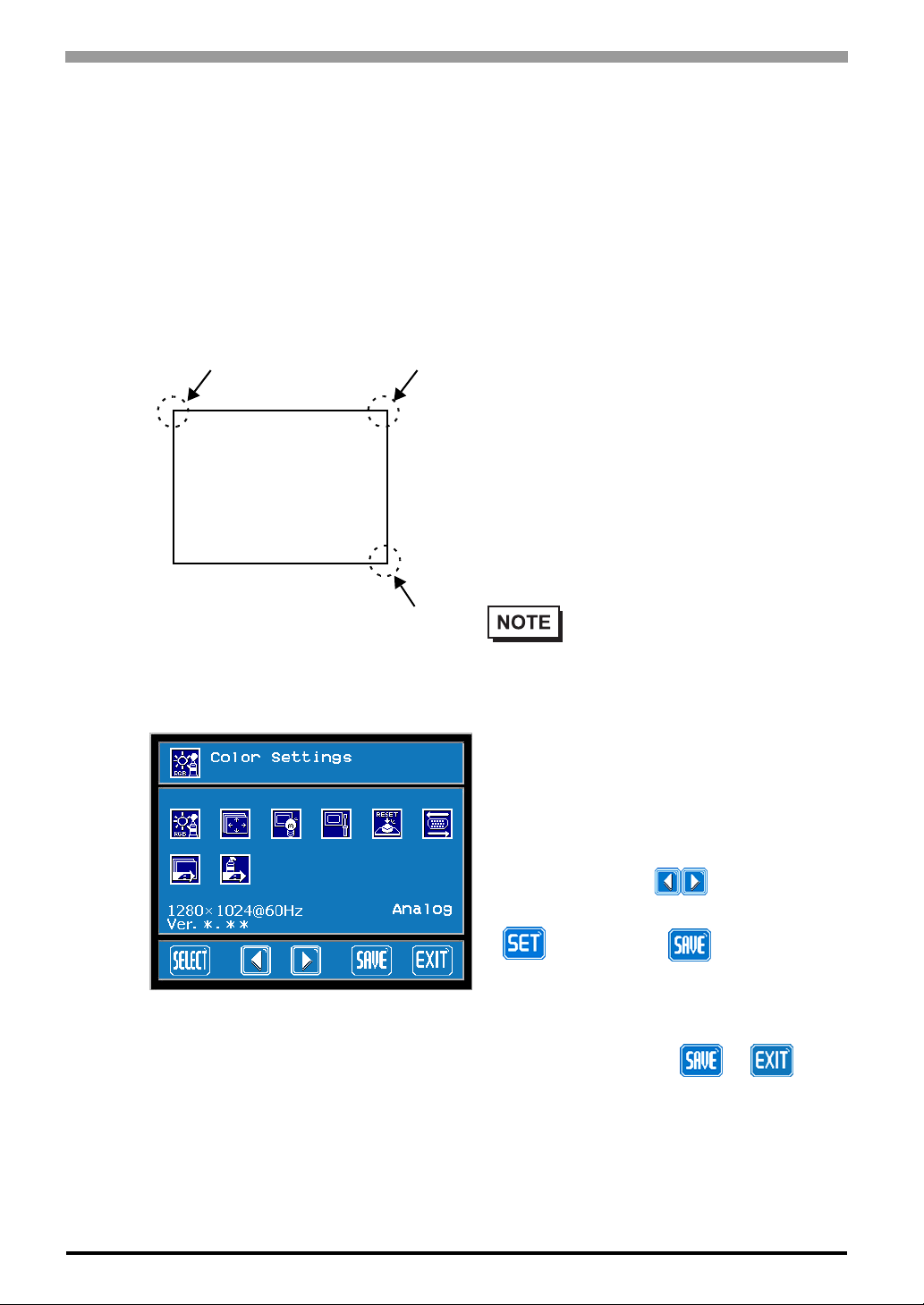
(1) How to start the OSD
(1) (2)
Displayed screen
(2) Main Menu
(3)
Starting the OSD
To sta rt the OSD and ente r OSD mode, pres s the three
corners of the touch panel in the following order
(upper left (1) a upper right (2) a lower right (3))
within 5 seconds. In OSD mode, the setting screen is
displayed in the center of the screen. In this mode, the
touch panel cannot be used to export data to external
devices unless the settings for the OSD are completed.
• OSD is not displayed when a SW
1-2 is ON.
Using the OSD
Icons on the screen are used to operate the OSD.
When you start up the OSD, the top menu displays.
Touching the icon of the item you want to adjust
displays its submenu or setting change screen. In the
4-4
“Ver.*.**” indicates the version of the OSD.
setting change screen, icons are used to
change the setting. To set the setting, press the
button. Press the button to save the
defined settings.
Quitting the OSD
To quit the OSD, press the or button
in the top menu or leave the OSD as it is for at least
30 seconds.
Page 58
Chapter 4 Setting up and Adjusting the FP unit
• In the OSD, pressing the button applies the set value and enables the
setting. The set value won't be canceled unless the power is turned OFF or
the value is reset.
If the power is turned OFF without saving the set value, that data will
disappear. The last saved data will be read into the system when the FP
starts. To enable the changed value, be sure to press the button.
• All the setting values, even though in process of the OSD settings, will be
retained in condition of letting the OSD leave more than 30 seconds or by
pressing the button. The OSD will keep those values and make them
effective until power-off or a Reset command input.
4-5
Page 59
FP-3900T Series User Manual
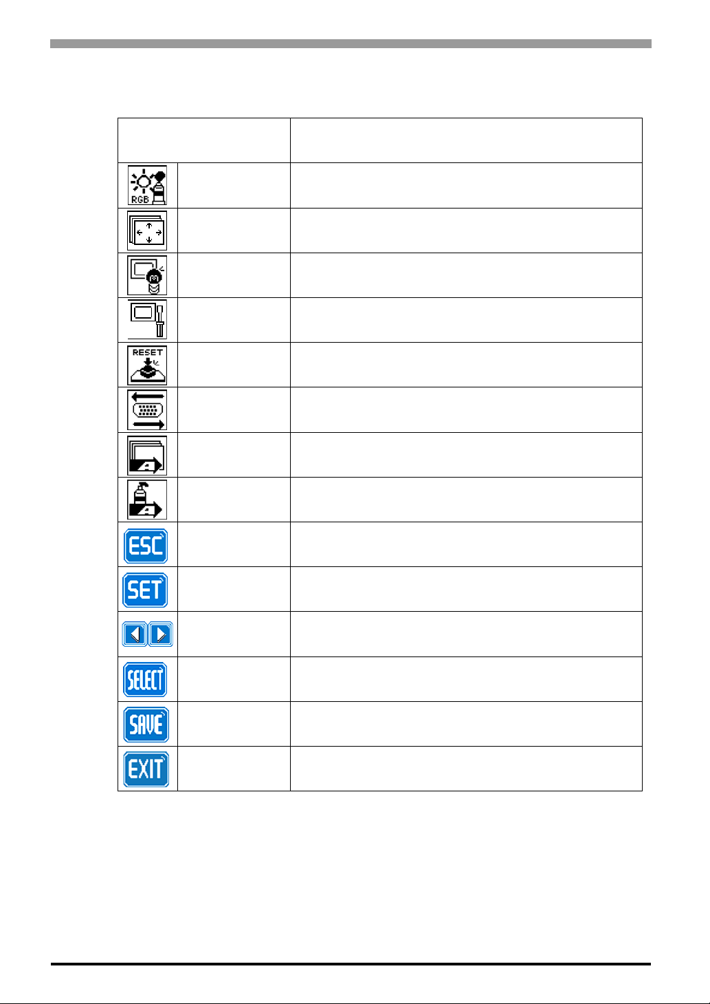
4.2.2 OSD Setting Icons
Item Function
Color Settings Adjusts the contrast and the brightness.
Screen Settings
Custom Display Adjusts Sharpness and the backlight brightness.
System Settings Changes settings such as activating the click sound.
All Reset Resets the current OSD value to the default value.
Input Source Switches Analog RGB and DVI-D.
Auto Adjust
Auto Gain
ESC Cancels the setting and returns to the upper level.
SET Applies the setting and returns to the upper level.
Adjusts the display position of the screen.
(Analog RGB only)
Automatically adjusts the display position of the screen.
(Analog RGB only)
Automatically adjusts the contrast and the brightness.
(Analog RGB only)
4-6
Arrow KEY Changes the selection.
SELECT Selects icons or items.
SAVE Saves the current value and quits the OSD.
EXIT Quits the OSD.
Page 60
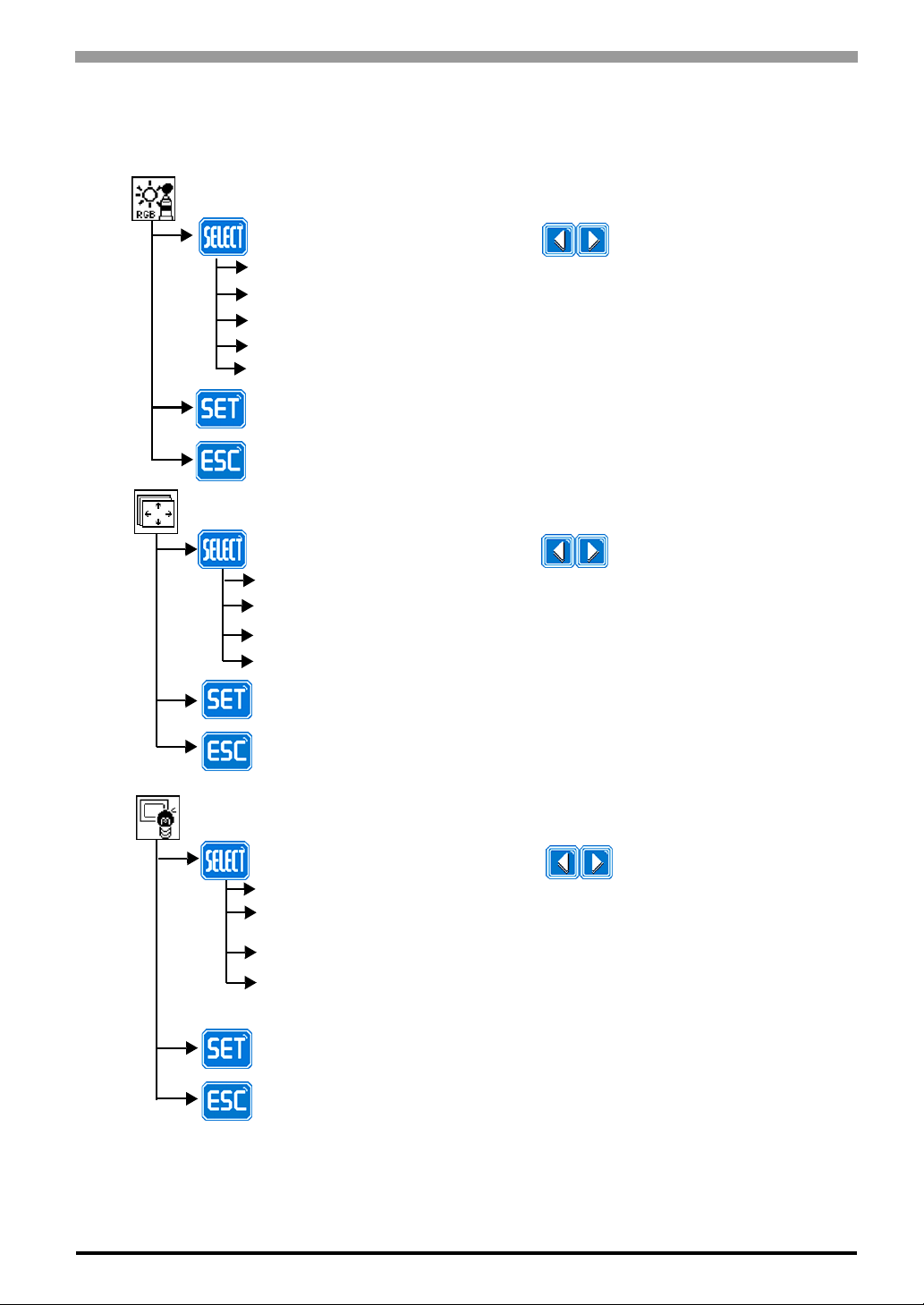
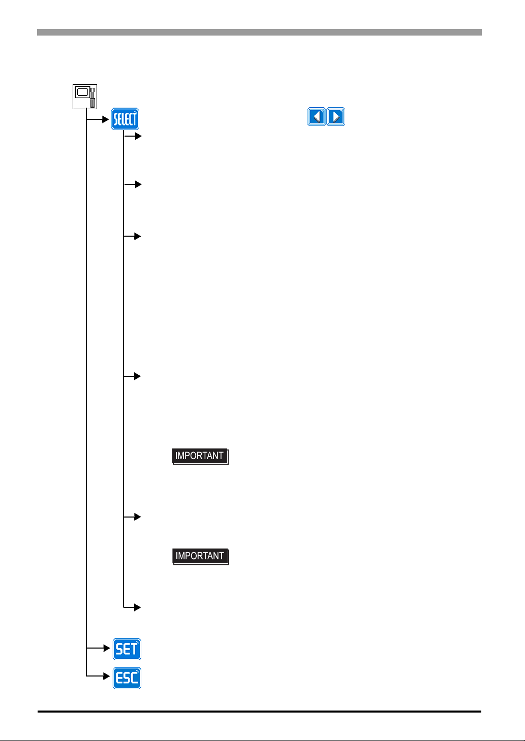
4.2.3 OSD Setting Item Details Main Menu
Color Settings
Chapter 4 Setting up and Adjusting the FP unit
Selection of the change item
Contrast
R.Contrast
G.Contrast
B.Contrast
Brightness
Applies the setting and then returns to the top menu.
Cancels the setting and then returns to the top menu.
Screen Settings (Analog RGB only)
Selection of the change item
H.Position
V.Position
H.size
Phase
Applies the setting and then returns to the top menu.
Cancels the setting and then returns to the top menu.
Adjustment button
Adjusts the contrast.
Adjusts the R.contrast.
Adjusts the G.contrast.
Adjusts the B.contrast.
Adjusts the Brightness.
Adjustment button
Adjusts the horizontal position.
Adjusts the vertical position.
Adjusts the horizontal size.
Adjusts the clock phase.
Custom Display
Selection of the change item
Sharpness
Dimmer
Auto Adjust Enable
OSD Transparent
Applies the setting and then returns to the top menu.
Cancels the setting and then returns to the top menu.
Adjustment button
Adjusts sharpness.
Adjusts the backlight brightness.
Enables/disables the function to adjust the screen position
automatically. (Default: Enable)
Adjusts the OSD transmittance.
4-7
Page 61
FP-3900T Series User Manual
System Settings
Selection of the change item
Click Tone
720x400 Mode
Auto off Disp
BL Alarm
Enables/disables the click sound. With this parameter , the sound
level can also be adjusted.
(Default value: OFF <Click sound disabled>)
When an input data resolution of 720 x 400 is used in the VGA text
mode, set this parameter to ON. For other resolutions, set this
parameter to OFF.
(Default: OFF)
Enables/disables the screen display Auto OFF function and sets the
time when the Auto OFF function is enabled.
(Default: OFF <Auto OFF function disabled>)
The Auto OFF function automatically turns off the display to
prevent the screen from burning out when the touch panel is not
used for some period of time. With this parameter, you can set the
time interval to turn off the screen display (how much time passes
before the screen display is turned off) when the touch panel is not
used. If the touch panel is not touched over the set time, the
backlight will automatically turns off.
Select the time period from 1 min, 3 min, 5 min, 10 min, and OFF
(Auto OFF function disabled).
Enables/disables the Backlight burnout detect function.
(Default: ON)
When a burned-out backlight is detected, the Front LED flashes
alternately green and red, or a steady orange.
Touch-operation will be disabled when the backlight burns out,
which prevents the FP from sending input signals to the PLC.
Adjustment button
4-8
• Normally, the FP unit detects a backlight burnout by
monitoring the backlight’s current flow, however, the
FP may fail to detect this condition, depending on the
type of backlight problem.
Detect 2-Point Touch
Power on Buzzer
Applies the setting and then returns to the top menu.
Cancels the setting and then returns to the top menu.
Enables/disables to halt the data output procedure when two points
of the touch panel are pressed. (Default: <Disable>)
• When doing the touch operation on a screen like the
desktop of Windows®, disable this function.
• Depending on the conditions, it may not be able to be
detected that the two points were pressed.
Enables/disables the buzzer sound in turning on the power.
(Default: OFF < Buzzer sound disabled>)
Page 62
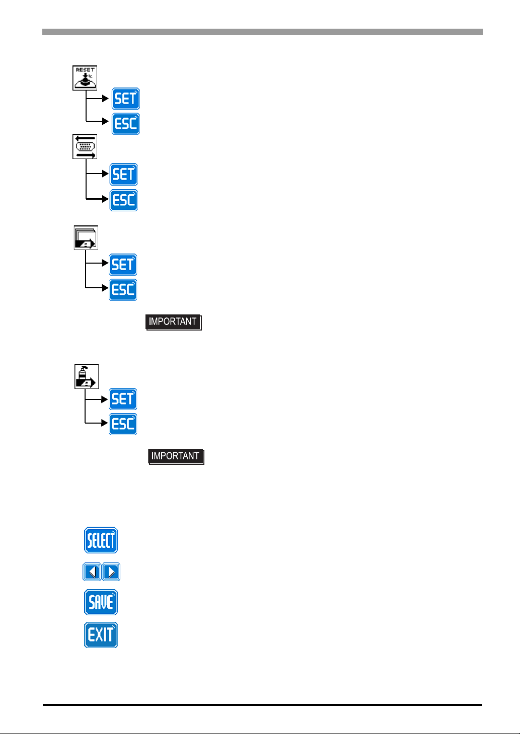
All Reset
Resets all the settings and then returns to the top menu.
Cancels the setting and then returns to the top menu.
Input Source
Applies the setting and then returns to the top menu.
Cancels the setting and then returns to the top menu.
Auto Adjust (Analog RGB only)
Applies the setting and then returns to the top menu.
Cancels the setting and then returns to the top menu.
Chapter 4 Setting up and Adjusting the FP unit
• Be sure to perform the auto adjust while things except the
Auto Gain (Analog RGB only)
Applies the setting and then returns to the top menu.
Cancels the setting and then returns to the top menu.
• Be sure to perform the auto gain control when the screen
Icon decision
Icon selection
Saves the setting and quits the OSD.
black are displayed on the edge of the screen.
has both 100% black and 100% white areas displayed.
Saves all the adjusted settings in the EEPROM.
End of OSD
4-9
Page 63

FP-3900TSeries User Manual
MEMO
4-10
Page 64

5 Touch Panel Data
1. Touch Interface Data
This chapter describes the outline of the software to input the touch panel data to the host computer.
5-1
Page 65
FP-3900T Series User Manual
5.1 Touch Interface Data
The FP-3900T Series units use an analog type touch panel. This touch panel needs a calibration program to
adjust the actual touch position.
The screen display origin point, with the resolution of 1280 × 1024 for FP-3900T Series units, is normally at
the upper left corner of the screen. Therefore, a software to convert the touch coordinates to display
coordinates is needed.
OS Touch I/F Program Calibration
®
Windows
Windows
Windows
NT4.0 SP6a or newer ver.
®
2000
®
XP
*1 The UPDD is used for both English and Japanese.
• Visit our support site below and download the mouse-emulation software
UPDD
*1
Feature included in
UPDD
(UPDD).
Digital Electronics Corporation’s support site - Otasuke Pro!
http://www.pro-face.com/otasuke/
• For use of USB for sending touch data, the number of the calibration point of
mouse emulation software sho uld be 9. (The initial setting is 4.)
If you don't change the setting values, the touch position may not be accurate, a
little off the point.
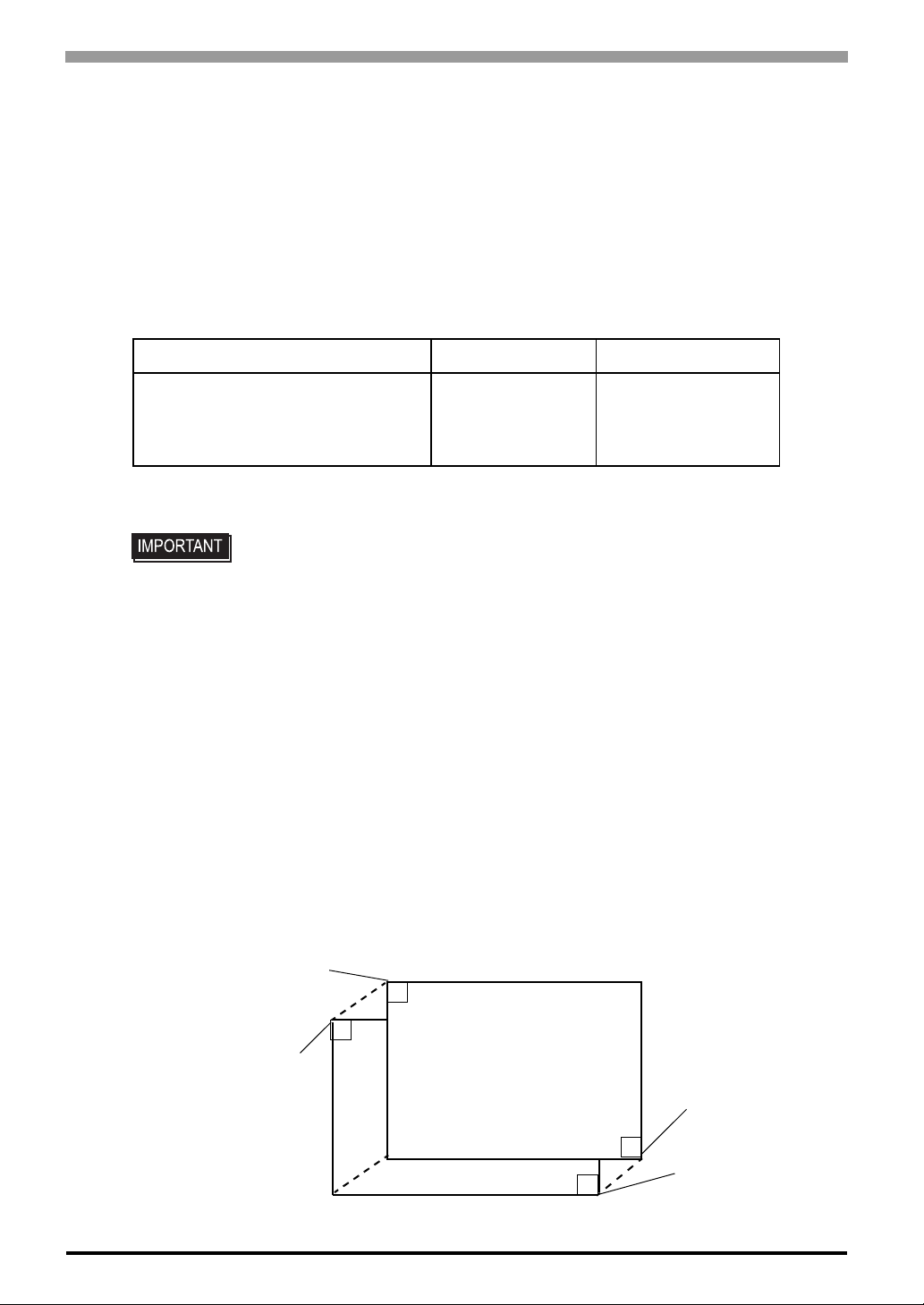
Touch Panel Coordinate Data
(1) Resolution
Both the X and Y coordinates have a resolution of 1024.
The origin point (0,0) is located in the upper left corner of the screen.
<FP-3900TSeries>
Touch Panel Coordinates
(0,0)
Display Coordinates
(0,0)
Touch Panel Coordinates
(1023,1023)
5-2
Display Coordinates
(1279,1023)
Page 66
(2) Data Format
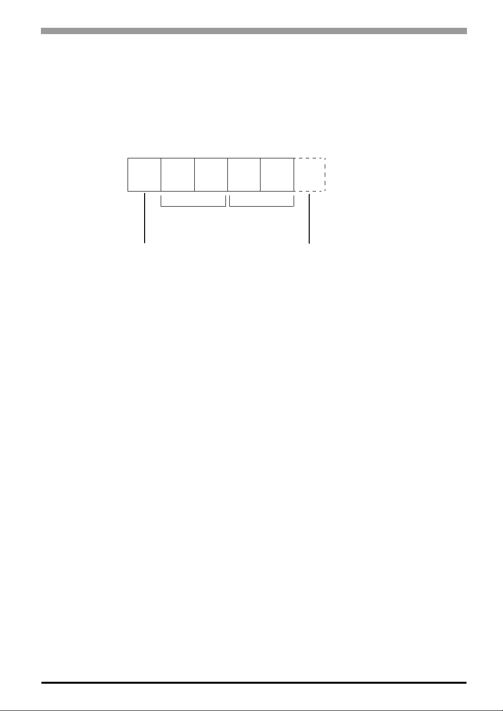
Touch Panel coordinate data is sent to the host using the following format.
All data is in binary format.
Header: 1 byte (11h= touch ed; 10h = released)
X coordinate: 2 bytes (0 to 3FFh)
Y coordinate: 2 bytes (0 to 3FFh)
X coordinate Y coordinate
Chapter 5 Touch Panel Data
11h
Added when touch is released.
<Example>
If the coordinate (X=23(11h), Y=500(1F4h)) is touched and moved to the coordinate (X=63(3Fh),
Y=250(FAh)).
11h 0h 17h 1h F4h touched
11h 0h 17h 1h F4h continuous output with the same location
11h 0h 18h 1h F5h moving without releasing touch
::
::
::
::
::
11h 0h 3Fh 1h FAh continuous data output unless finger is released
11h 0h 3Fh 1h FAh 10h when released, only 1 unit of data is sent
10h
5-3
Page 67

FP-3900T Series User Manual
MEMO
5-4
Page 68

6 Troubleshooting
1. Troubleshooting
2. Error Message
6-1
Page 69
FP-3900T Series User Manual
6.1 Troubleshooting
6.1.1 Possible Device Problems
This chapter explains the main method of dealing with the trouble in the use of the FP.
• For problems other than problems of the FP, please refer to the manual of each equipment.
Possible types of trouble while using this unit are as follows.
No display
• No display appears after the unit is switched on.
• The screen disappears during standard operation.
• The screen does not display normally.
Touch panel does not respond
• The touch panel does not respond when pressed. Its reaction time is abnormally long.
To prevent an electric shock, be sure the power cord is not connected when wiring the unit.
• This section assumes that the FP is the cause of a problem, not the host. When
the host is the problem, please refer to its corresponding manual.
6-2
Page 70
6.1.2 No Display
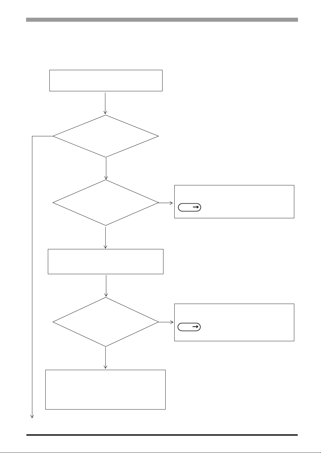
When the screen does not display when powering up, or if the screen turns OFF by itself, use the flowchart
below to find an appropriate solution.
YES
Does the backlight (CCFL)
Chapter 6 Troubleshooting
No Screen Display
light up?
NO
Is it using the correct
power voltage?
YES
Turn OFF the power switch.
Is the power supply
cable connected properly
to the unit?
YES
NO
NO
Connect the appropriate voltage.
SEE
Fix the power cable connection.
SEE
2 Specifications (page2-1)
3 Installation and Wiring (page3-1)
There is a problem with the FP unit. Please
contact your local FP distributor.
6-3
Page 71
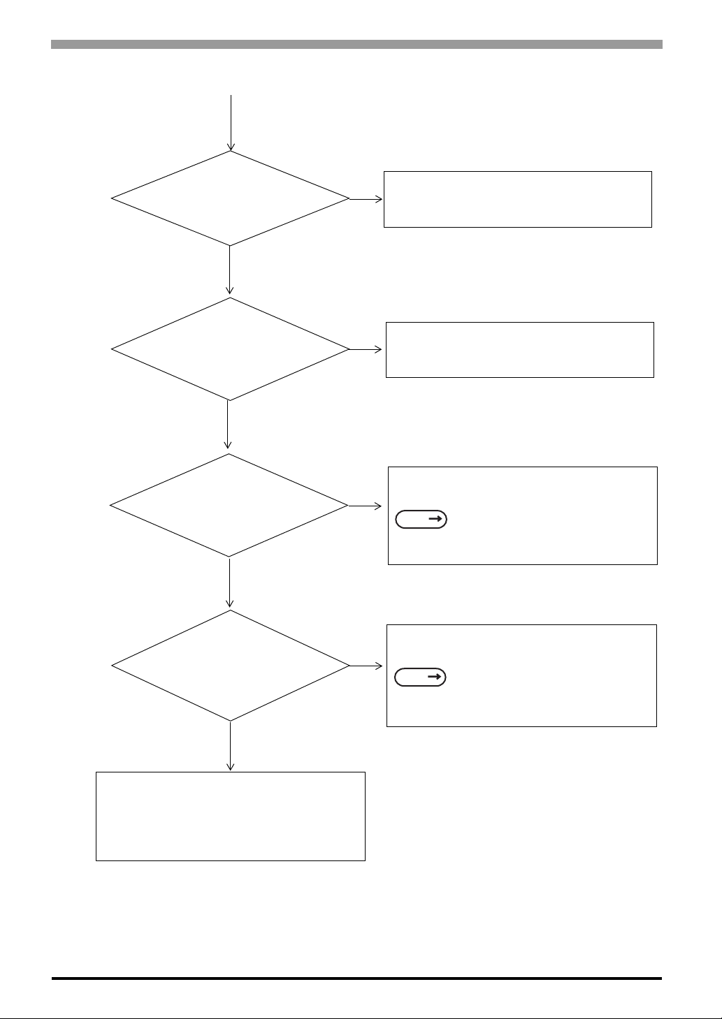
FP-3900T Series User Manual
NO
Is the PC operating?
YES
Are the FP output
settings the same as the
PC's frequency and
resolution?
YES
Is the RGB cable/
DVI-D cable connected
correctly?
YES
NO
NO
Start the PC.
Set the FP output settings so that they match
the PC’s frequency and resolution.
Connect the RGB cable/DVI-D cable correctly.
SEE
2.4 Cable Diagrams (page2-12)
6-4
Does the screen display
though display is not
normal.
NO
There is a problem with the FP unit. Please
contact your local FP distributor.
YES
Adjust the screen display position.
SEE
4.2 Screen Display Adjustment (page4-
4)
Page 72
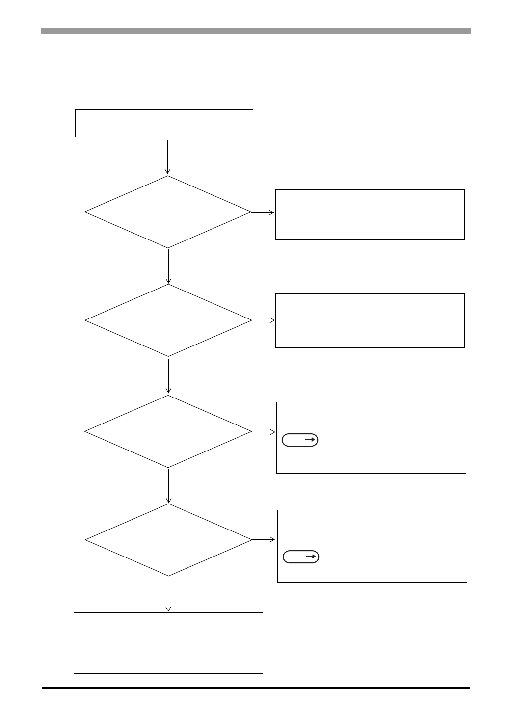
6.1.3 Touch Panel Does Not Respond
When the touch panel does not react, or its reaction is very slow after it is pressed, follow the flowchart below
to find the origin of the problem and the appropriate solution.
Touch panel is not working
Is the Mouse Emulation
Software installed in PC
(Host)?.
YES
Is the Mouse Emulation
Software set correctly?
Chapter 6 Troubleshooting
Install the Mouse Emulation Software.
NO
For details, Refer to the “Installation Guide”
(PDF file) which is supplied with the Mouse
Emulation Software.
Set the Mouse Emulation Software correctly.
NO
For details, Refer to the “Installation Guide”
(PDF file) which is supplied with the Mouse
Emulation Software.
YES
Is the Slide Switch
correctly set for the input
interface.
YES
Is the SIO or USB cable
connected correctly?
YES
There is a problem with the FP unit. Please
contact your local FP distributor.
NO
NO
Set the Slide Switch correctly.
SEE
Connect the SIO or USB cable correctly.
SEE
4.1.1 Preset Settings and Adjustments
for Dip Switch and Slide Switch
(page4-2)
2.4 Cable Diagrams (page2-12)
6-5
Page 73
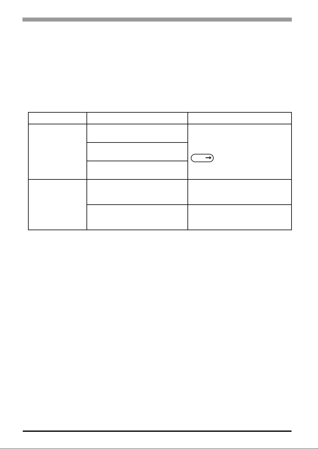
FP-3900T Series User Manual
6.2 Error Message
This section explains the messages that appear when an error has occurred in the
FP unit during RUN mode.The problem causing the error message and its
related countermeasure are explained in the table below.
(Only the latest error message will appear on the FP screen)
6.2.1 Error Message List
Error Message Problem Solution
Out of range
No signal
Signal timing has been input that is
not compatible with the FP unit.
The dot clock has greatly exceeded of
the FP units usable timing range.
Resolution has been set that is not
compatible with the FP unit.
The PS-2000B unit or a Windowscompatible PC's power has not been
turned ON.
The PS-2000B unit or a Windowscompatible PC has not been correctly
connected to the FP unit.
Set the FP Output settings so that they
match the PC’s frequency and
resolution.
SEE
Turn on the PS-2000B unit or a
Windows-compatible PC’s power.
Connect the RGB cable/DVI-D cable
correctly.
2.3 Interface Specifications
(page2-5)
6-6
Page 74

7 Maintenance
1. Regular Cleaning
2. Periodic Check Points
3. Backlight Replacement
This chapter indicates necessary cautions and instruction standards to maintain your FP.
7-1
Page 75
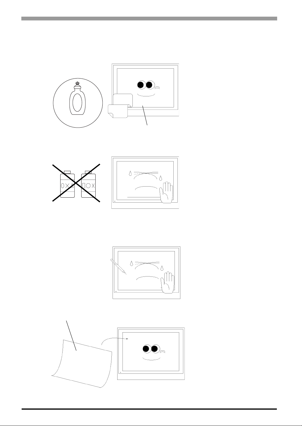
FP-3900T Series User Manual
7.1 Regular Cleaning
7.1.1 Cleaning the Display
OK!
Neutral detergent
NG!
Thinner
Organic solvent
Strong acid
When the display surface or frame
become dirty, use a soft cloth moistened
with neutral detergent to wipe away any
dust or stains.
Display
Do not clean the unit with thinner,
organic solvents, or strong acids.
7-2
Do not use sharp or hard objects, such as
a mechanical pencil or screwdriver, to
push on the display. This could damage
the unit.
Protection sheet
Attach the screen protection sheet when
using the FP in extremely dirty or dusty
areas.
Page 76
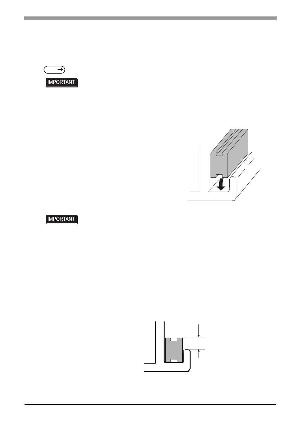
7.1.2 Installation Gasket Replacement
The installation gasket protects the FP and improves its water resistance. For instructions on installing the FP
unit's gasket, refer to the following page.
Chapter 7 Maintenance
SEE
3 Installation and Wiring (page3-1)
• A gasket which has been used for a long period of time may have scratches or
dirt on it, and could have lost much of its water resistance. Be sure to change the
gasket at least once a year, or when scratches or dirt become visible.
Installation Gasket Replacement Procedure
(1) Place the FP on a flat, level surface with the display
facing downwards.
(2) Remove the old gasket from the FP.
(3) Attach the new gasket to the FP. Be sure to insert the
gasket into the FP unit’s groove so that the gasket’s
groove sides are vertical.
(4) Check if the gasket is attached to the FP correctly.
The upper surface of the gasket should protrude
approximately 2mm out from the groove.
• The gasket must be inserted correctly into the groove for the FP unit’s moisture
resistance to be equivalent to IP65f.
• Be sure the gasket's seam is not inserted into any of the unit's corners, only in the
straight sections of the groove. Inserting it into a corner may lead to its eventually
tearing.
• Install the gasket as it comes to the under side of the display area. Otherwise it
could not sufficiently prevent from dust and water.
• The upper surface of the gasket should protrude approximately 2mm out from the
groove. Be sure to check that the gasket is correctly inserted before installing the
FP into a panel.
unit: mm[in.]
2.0[0.08]
7-3
Page 77

FP-3900T Series User Manual
7.2 Periodic Check Points
To keep your FP unit in its best condition, please inspect the following points periodically.
FP Operation Environment
• Is the environmental temperature within the allowable range (0ºC to 50ºC)?
• Is the environmental humidity within the specified range (10%RH to 90%RH, dry bulb temperature of
39ºC or less)?
• Is the operating atmosphere free of corrosive gasses?
Electrical Specifications
• Is the Ra ted Voltage Range appropriate?
FP Model Number Rated Voltage Range
FP3900-T41-U
FP3900-T41
AC85 ~ 264V
Rated Items
• Are all power cords and cables connected properly? Have any become loose?
• Are all insta ll ati on fasteners holding the unit securely?
• Are there any scratches or traces of dirt on the installation gasket?
7-4
Page 78

7.3 Backlight Replacement
• FP-3900T series backlights cannot be replaced by customers. When you need to
replace the backlight of your FP-3900T, contact your local distributor.
Chapter 7 Maintenance
7-5
Page 79

FP-3900T Series User Manual
MEMO
7-6
 Loading...