

Page 1

WM240
2.4GHz Digital Wireless Microphone System
USER’S MANUAL
ITALIANO
ENGLISH
96MAN0099-RE V.28/14
Page 2

2
Page 3

3
English Index
DISPOSAL OF OLD ELECTRICAL & ELECTRONIC EQUIPMENT ....................................................................4
SAFETY INSTRUCTIONS .............................................................................................................................4
IN CASE OF FAULT .....................................................................................................................................4
PACKAGING, SHIPPING AND COMPLAINT ................................................................................................4
WARRANTY AND PRODUCTS RETURN ......................................................................................................4
MAINTENANCE AND DISCLAIMER ............................................................................................................5
POWER SUPPLY .........................................................................................................................................5
USER’S WARNINGS AND CE CONFORMITY ...............................................................................................5
INTRODUCTION ........................................................................................................................................6
DESCRIPTION ............................................................................................................................................6
WM240 RECEIVER .....................................................................................................................................6
PAIRING OPERATION ................................................................................................................................7
WM24M HANDHELD TRANSMITTER ........................................................................................................7
WM24B BODYPACK TRANSMITTER ..........................................................................................................7
TECHNICAL SPECIFICATION .......................................................................................................................8
Page 4

4
DISPOSAL OF OLD ELECTRICAL & ELECTRONIC EQUIPMENT
This marking shown on the product or its literature, indicates that it should not be disposed with
other household wastes at the end of its working life. To prevent possible harm to the enviroment
or human health from uncontrolled waste disposal, please separate this from other types of
wastes and recycle it responsibly to promote the sustainable reuse of material resources.
Household users should contact either the retailer where they purchased this product, or their
local government office, for details of where and how they can take this item for environmentally safe
recycling. Business users should contact their supplier and check the terms and conditions of the purchase
contract. This product should not be mixed with other commercial wastes for disposal.
SAFETY INSTRUCTIONS
• CAUTION - Before using this product read carefully the following safety instructions. Take a look of this
manual entirely and preserve it for future reference. When using any electric product, basic precautions
should always be taken, including the following:
• To reduce the risk, close supervision is necessary when the product is used near children.
• Protect the apparatus from atmospheric agents and keep it away from water, rain and high humidity
places.
• This product should be site away from heat sources such as radiators, lamps and any other device that
generate heat.
• Care should be taken so that objects and liquids do not go inside the product..
• The product should be connected to a power supply only of the type described on the operating
instructions or as marked on the product.
IN CASE OF FAULT
• In case of fault or maintenance this product should be inspected only by qualified service personnel
when:
Liquids have spilled inside the product.
The product has fallen and been damaged.
The product does not appear to operate normally or exhibits a marked change in performance.
• Do not operate on the product, it has no user-serviceable parts inside.
• Refer servicing to an authorized maintenance centre.
PACKAGING, SHIPPING AND COMPLAINT
• This unit package has been submitted to ISTA 1A integrity tests. We suggest you control the unit
conditions immediately after unpacking it.
• If any damage is found, immediately advise the dealer. Keep all unit packaging parts to allow inspection.
• Proel is not responsible for any damage that occurs during shipment..
• Products are sold “delivered ex warehouse” and shipment is at charge and risk of the buyer.
• Possible damages to unit should be immediately notified to forwarder. Each complaint for manumitted
package should be done within eight days from product receipt.
WARRANTY AND PRODUCTS RETURN
• Proel products have operating warranty and comply their specifications, as stated by manufacturer..
• Proel warrants all materials, workmanship and proper operation of this product for a period of two years
from the original date of purchase. If any defects are found in the materials or workmanship or if the
product fails to function properly during the applicable warranty period, the owner should inform about
Page 5

5
these defects the dealer or the distributor, providing receipt or invoice of date of purchase and defect
detailed description. This warranty does not extend to damage resulting from improper installation,
misuse, neglect or abuse. Proel S.p.A. will verify damage on returned units, and when the unit has been
properly used and warranty is still valid, then the unit will be replaced or repaired. Proel S.p.A. is not
responsible for any "direct damage" or "indirect damage" caused by product defectiveness.
MAINTENANCE AND DISCLAIMER
• Clean only with dry cloth.
• Proel products have been expressly designed for audio application, with signals in audio range (20Hz to
20kHz). Proel has no liability for damages caused in case of lack of maintenance, modifications, improper
use or improper installation non-applying safety instructions.
• Proel S.p.A. reserves the right to change these specifications at any time without notice..
• Proel S.p.A. declines any liability for damages to objects or persons caused by lacks of maintenance,
improper use, installation not performed with safety precautions and at the state of the art.
POWER SUPPLY
• This apparatus should only be connected to power source type specified in this owner’s manual or on the
unit.
• If the supplied AC power cable plug is different from the wall socket, please contact an electrician to
change the AC power plug.
• Hold the plug and the wall outlet while disconnecting the unit from AC power.
• If the unit will not be used for a long period of time, please unplug the power cord from AC power outlet.
• To avoid unit power cord damage, please do not strain the AC power cable and do not bundle it.
• In order to avoid unit power cord damage, please ensure that the power cord is not stepped on or
pinched by heavy objects.
USER’S WARNINGS AND CE CONFORMITY
• Changes or modifications not expressly approved by Proel S.p.A. could void your authority to operate the
equipment.
• This wireless system operates in the globally available ISM band 2404 MHz to 2476 MHz. The operation
does not require a user license.
• PROEL S.p.A hereby, declares that this wireless microphone system complies with the essential
requirements and other relevant provisions of:
• Directive LVD 2006 / 95 / EC as stated in EN 60065 standard.
• Directive 2009 / 125 / CE (Ecodesign) as stated in EC regulation n.278 / 2009.
• Directive 2013 / 35 / UE (electromagnetic field exposure) as stated in EN 62479 standard.
• Directive R&TTE 1999 / 5 / EC as stated in EN 300328; EN 301489-01; EN 300489-09 standard.
• The full and detailed declaration of conformity can be downloaded from the web site:
www.proel.com
Page 6

6
INTRODUCTION
Thank you for choosing this PROEL product and for your trust in our brand, synonymous of professionalism,
accuracy, high quality and reliability. All our products are CE approved and designed for continuous use in
professional systems.
DESCRIPTION
The WM240 series of wireless microphones works in the 2.4 GHz free frequency range and it takes advantage
all the PROEL experience in the wireless technology for audio applications. The intelligent frequency hopping
can help to avoid interference effectively and ensures good performances and the maximum reliability. The
WM240 is the perfect tool for wireless audio applications in small and medium size environments, combining
performances, reliability and sturdiness and avoiding all the problems related to the interferences of digital
TV.
WM240 Digital Wireless Microphone system features 3 units: WM240 receiver, WM24M handheld
transmitter and WM24B body pack transmitter. The system is available in two different configurations:
WM240M : WM240 + WM24M
WM240B : WM240 + WM24B
Features:
- Operating Band: ISM 2.4 GHz free band
- GFSK digital modulation/demodulation
- Intelligent Frequency Hopping
- Automatic mute in case of bad quality transmission or high error code rate
- Memorization of matched devices
- Up to 2 systems usable in the same location (depending on the circumstances)
- Up to 25 meters (100 ft) transmit distance range in open place
WM240 RECEIVER
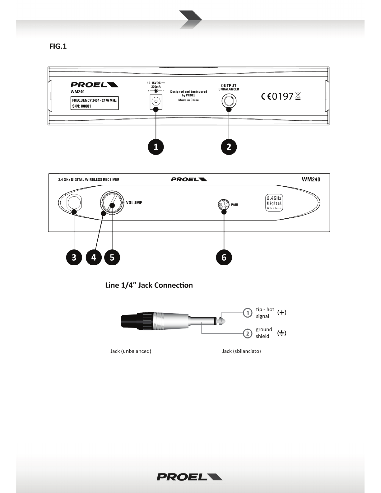
(see FIG. 1 at page 15)
1. 12-15VDC IN
Socket for the AC/DC adaptor connection: use only the adaptor supplied with the system.
2. OUTPUT (UNBALANCED)
Unbalanced audio output with line level: connect it through a 6.3mm jack cable to a mixer input.
3. ANTENNA
This is the receiving antenna. Raise it up during the use and, to obtain a better reception, place the
receiver away from other metal objects and distant no more than 25 m (100 ft) from the transmitter.
4. STATUS L E D
This BLUE LED shows the operative status of the receiver:
- Low intensity: it indicates that the transmitter signal is not present, meaning that the transmitter is
turned off or it is not paired with the receiver.
- High intensity: it indicates that the transmitter is on and it is paired with the receiver.
- Intermittent Low and High intensity: the receiver is in pairing status (see below) and it is ready to be
paired with a transmitter.
5. VOLUME
Volume potentiometer: set this control to a proper level that doesn’t overload the mixer input channel.
6. PAIR BUTTON
This button is illuminated when there is a power DC. Press this button to start the pairing operation, in
order to couple the receiver with a transmitter (read carefully the following text box).
Page 7
7
PAIRING OPERATION
• PRESS AND HOLD the PAIR button on the receiver for 5 seconds (the STATUS LED will flash and an
intermittent tone is heard at the output for approximately 12 seconds).
• PRESS AND HOLD the MUTE button on the transmitter until its LED flashes.
• To confirm the pairing the receiver STATUS LED lights permanently at HIGH intensity: now you
can hear the audio signal from the receiver’s output. If the receiver STATUS LED lights at LOW
intensity, the pairing operation was not successful: try again.
NOTE: in particular circumstances, for example with many WI-FI devices in the same location, the
pairing between transmitter and receiver could be difficult (STATUS LED lights HIGH for a limited
time and then will light LOW, with no output signal). In this case try to repeat the pairing
operation until you have a more stable transmission.
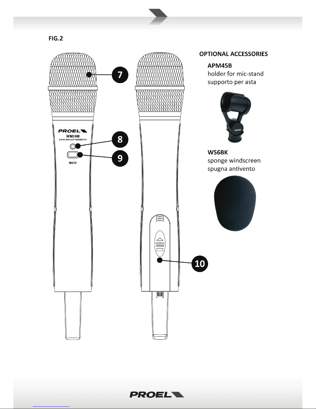
WM24M HANDHELD TRANSMITTER
(see FIG. 2 at page 16)
7. MICROPHONE GRILLE
The grille protects the microphone capsule and includes a anti-pop filter. The microphone capsule is
dynamic type with a cardioid unidirectional figure.
8. STATUS L E D
Green LED that shows the transmitter status:
• When the microphone is switched on, the green LED is on.
• When the microphone is switched off (MUTE), the green LED in off.
• If the batteries are exhausted, the green LED flashes: replace the batteries as soon as possible.
• The green LED flashes also when the pairing operation is activated and it continue to flash until the
operation is terminated.
9. MUTE
On/off switch: this switch is also used to start the pairing between transmitter with receiver (refer to the
above text box).
10. BATTERIES COVER
Sliding down the slot cover in the lower part of the microphone body you can access the battery inlet. To
operate the microphone needs 2 type AA alkaline batteries.
NOTE: remove always the batteries if you don’t use the transmitter for a long period of time, in order to
avoid the battery premature discharge and the annoying corrosion of battery contacts.
(The figure shows some optional accessories available from the PROEL catalogue.)
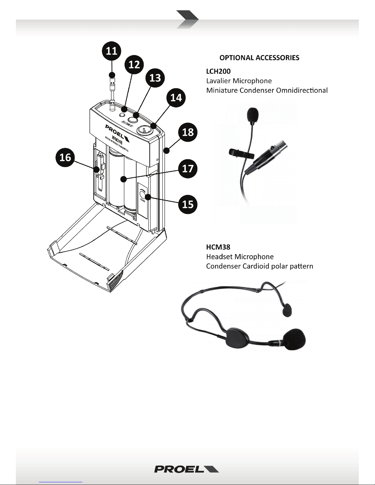
WM24B BODYPACK TRANSMITTER
(see FIG. 3 at page 16)
11. ANTENNA
This is the transmitting antenna: do not force, disconnect or try to replace with a different one.
12. STATU S L ED
Green LED that shows the transmitter status:
• When the bodypack is switched on, the green LED is on.
• When the bodypack is switched off (MUTE), the green LED in off.
• If the batteries are exhausted, the green LED flashes: replace the batteries as soon as possible.
• The green LED flashes also when the pairing operation is activated and it continue to flash until the
operation is terminated.
Page 8

8
13. MUTE
On/off switch: this switch is also used to start the pairing between transmitter with receiver (refer to the
above text box).
14. AUDIO INPUT
T4AM mini XLR input socket to connect the supplied instrument cable or an optional microphone.
15. GAIN
Using the supplied screwdriver and rotating this trimmer is possible to optimize the gain of the
microphone connected to the bodypack. Rotate it clockwise if you want an higher gain (speaking) or
rotate it counter-clockwise if you want a lower gain (singing).
16. SCREWDRIVER
This is the supplied mini screwdriver for the GAIN adjustment.
17. BATTERIES COVER
Sliding down the lower part of the bodypack you can access the battery inlet.
To operate the microphone needs 2 type AA alkaline batteries.
NOTE: remove always the batteries if you don’t use the transmitter for a long period of time, in order to
avoid the battery premature discharge and the annoying corrosion of battery contacts.
18. CLIP
Clip to hook the bodypack to the belt.
The bodypack is supplied with a 6.3 mm (1/4”) JACK cable adaptor that can be used with most of the
instruments equipped with this type of audio output. The figure shows also some optional microphones
available from the PROEL catalogue.
TECHNICAL SPECIFICATION
WM240 – Receiver
SN Ratio
>89 dB
Frequency Range
2.404 – 2.476 GHz
Transmission Delay
18.3 mS
RF Sensitivity
-78 dB
Power Supply Battery
2x1.5V AA alkaline type
Frequency Response
50 Hz – 15 KHz
Operating time
Up to 20 hours
Sampling
16 bit @ 38.5KHz
Dimensions
H: 287 x Ø: 47 mm
THD
<0.05% @ 1KHz
SN Ratio
>89 dB
WM24B – Bodypack Transmitter
Transmission Delay
18.3 mS
Frequency Range
2.404 – 2.476 GHz
Output Connector
Unbalanced ¼” Jack
Transmitting Power
< 10 dBm
Power Supply
DC 12 V - 200 mA
Transmission Distance
Up to 25m (open space)
Dimensions (LxWxH)
215 x 115 x 48 mm
Frequency Response
50 Hz – 15 KHz
Sampling
16 bit @ 38.5KHz
WM24M – Handheld Transmitter
THD
<0.05% @ 1KHz
Frequency Range
2.404 – 2.476 GHz
SN Ratio
>89 dB
Transmitting Power
< 10 dBm
Transmission Delay
18.3 mS
Transmission Distance
Up to 25m (open space)
Input Connector
TA4M
Frequency Response
50 Hz – 15 KHz
Power Supply Battery
2x1.5V AA alkaline type
Sampling
16 bit @ 38.5KHz
Operating time
Up to 20 hours
THD
<0.05% @ 1KHz
Dimensions (LxWxH)
62 x 22 x 85 mm
Page 9

9
Indice Italiano
TRATTAMENTO DEL DISPOSITIVO ELETTRICO OD ELETTRONICO A FINE VITA ...................................... 10
AVVERTENZE PER LA SICUREZZA ........................................................................................................... 10
IN CASO DI GUASTO ............................................................................................................................... 10
IMBALLAGGIO, TRASPORTO E RECLAMI ................................................................................................ 10
GARANZIE E RESI .................................................................................................................................... 11
MANUTENZIONE E LIMITAZIONI D’USO ................................................................................................ 11
ALIMENTAZIONE .................................................................................................................................... 11
AVVERTENZE PER L’UTILIZZO E CONFORMITÀ CE ................................................................................. 11
INTRODUZIONE ...................................................................................................................................... 13
DESCRIZIONE.......................................................................................................................................... 13
RICEVITORE WM240 .............................................................................................................................. 13
OPERAZIONE DI ABBINAMENTO ............................................................................................................ 14
TRASMETTITORE A MANO WM24M ...................................................................................................... 14
TRASMETTITORE BODYPACK WM24B ................................................................................................... 14
CARATTERISTICHE TECNICHE ................................................................................................................. 15
Page 10

10
TRATTAMENTO DEL DISPOSITIVO ELETTRICO OD ELETTRONICO A FINE VITA
Il marchio riportato sul prodotto o sulla documentazione indica che il prodotto non deve essere
smaltito con altri rifiuti domestici al termine del ciclo di vita. Per evitare eventuali danni
all’ambiente si invita l’utente a separare questo prodotto da altri tipi di rifiuti e di riciclarlo in
maniera responsabile per favorire il riutilizzo sostenibile delle risorse materiali. Gli utenti
domestici sono invitati a contattare il rivenditore presso il quale è stato acquistato il prodotto o
l’ufficio locale preposto per tutte le informazioni relative alla raccolta differenziata e al riciclaggio per questo
tipo di prodotto. Gli utenti aziendali sono invitati a contattare il proprio fornitore e verificare i termini e le
condizioni del contratto di acquisto. Questo prodotto non deve essere smaltito unitamente ad altri rifiuti
commerciali.
AVVERTENZE PER LA SICUREZZA
• ATTENZIONE - Prima di utilizzare il prodotto, si prega di leggere attentamente le seguenti istruzioni per la
sicurezza. Prendere visione del manuale d’uso e conservarlo per successive consultazioni. Durante l’uso
di un prodotto elettrico devono essere sempre prese precauzioni di base onde evitare danni a cose o
persone, incluse le seguenti:
• In presenza di bambini, controllare che il prodotto non rappresenti un pericolo.
• Posizionare l’apparecchio al riparo dagli agenti atmosferici e a distanza di sicurezza dall’acqua, dalla
pioggia e dai luoghi ad alto grado di umidità.
• Collocare o posizionare il prodotto lontano da fonti di calore quali radiatori, griglie di riscaldamento e
ogni altro dispositivo che produca calore.
• Evitare che qualsiasi oggetto o sostanza liquida entri all’interno del prodotto.
• Il prodotto deve essere connesso esclusivamente alla alimentazione elettrica delle caratteristiche
descritte nel manuale d’uso o scritte sul prodotto.
IN CASO DI GUASTO
• In caso di guasto o manutenzione questo prodotto deve essere ispezionato da personale qualificato
quando:
Sostanze liquide sono penetrate all’interno del prodotto.
Il prodotto è caduto e si è danneggiato.
Il prodotto non funziona normalmente esibendo una marcato cambio di prestazioni.
• Non intervenire sul prodotto.
• Rivolgersi a un centro di assistenza autorizzato Proel.
IMBALLAGGIO, TRASPORTO E RECLAMI
• L’imballo è stato sottoposto a test di integrità secondo la procedura ISTA 1A. Si raccomanda di controllare
il prodotto subito dopo l’apertura dell’imballo.
• Se vengono riscontrati danni informare immediatamente il rivenditore. Conservare quindi l’imballo
completo per permetterne l’ispezione.
• Proel declina ogni responsabilità per danni causati dal trasporto.
• Le merci sono vendute “franco nostra sede” e viaggiano sempre a rischio e pericolo del distributore.
• Eventuali avarie e danni dovranno essere contestati al vettore. Ogni reclamo per imballi manomessi
dovrà essere inoltrato entro 8 giorni dal ricevimento della merce.
Page 11

11
GARANZIE E RESI
• I Prodotti Proel sono provvisti della garanzia di funzionamento e di conformità alle proprie specifiche,
come dichiarate dal costruttore.
• La garanzia di funzionamento è di 24 mesi dopo la data di acquisto. I difetti rilevati entro il periodo di
garanzia sui prodotti venduti, attribuibili a materiali difettosi o difetti di costruzione, devono essere
tempestivamente segnalati al proprio rivenditore o distributore, allegando evidenza scritta della data di
acquisto e descrizione del tipo di difetto riscontrato. Sono esclusi dalla garanzia difetti causati da uso
improprio o manomissione. Proel SpA constata tramite verifica sui resi la difettosità dichiarata, correlata
all’appropriato utilizzo, e l’effettiva validità della garanzia; provvede quindi alla sostituzione o riparazione
dei prodotti, declinando tuttavia ogni obbligo di risarcimento per danni diretti o indiretti eventualmente
derivanti dalla difettosità.
MANUTENZIONE E LIMITAZIONI D’USO
• Pulire il prodotto unicamente con un panno asciutto.
• I Prodotti Proel sono destinati esclusivamente ad un utilizzo specifico di tipo sonoro: segnali di ingresso di
tipo audio (20Hz-20kHz). Proel declina ogni responsabilità per danni a terzi causati da mancata
manutenzione, manomissioni, uso improprio o installazione non eseguita secondo le norme di sicurezza.
• Proel S.p.A. si riserva di modificare il prodotto e le sue specifiche senza preavviso.
• Proel S.p.A. declina ogni responsabilità per danni a terzi causati da mancata manutenzione,
manomissioni, uso improprio o installazione non eseguita secondo le norme di sicurezza e a regola
d'arte.
ALIMENTAZIONE
• Il prodotto deve essere connesso esclusivamente alla alimentazione elettrica delle caratteristiche
descritte nel manuale d’uso o scritte sul prodotto.
• Se la spina in dotazione non combacia con la presa, rivolgersi ad un elettricista per far installare una
presa appropriata.
• Quando si scollega l’apparato alla rete tenere saldamente sia la spina che la presa.
• Quando l’unità non viene utilizzata per un periodo prolungato, interrompere l’alimentazione estraendo la
spina dalla presa dell’alimentazione.
• Per evitare danni alla linea d’alimentazione dell’apparato, non mettere in trazione il cavo d’alimentazione
e non utilizzare un cavo attorcigliato.
• Per evitare il danneggiamento del cavo d’alimentazione dell’apparato, assicurarsi che questo non venga
calpestato o schiacciato da oggetti pesanti.
AVVERTENZE PER L’UTILIZZO E CONFORMITÀ CE
• Modifiche non espressamente approvate da Proel S.p.A. possono invalidare l’autorizzazione ad operare
dell’apparecchiatura.
• Questo sistema wireless funziona nella banda ISM compresa tra 2404 MHz e 2476 MHz disponibile a
livello mondiale. Pertanto per il suo utilizzo non occorre disporre di una licenza individuale.
• PROEL S.p.A dichiara che il sistema di radiomicrofono è conforme ai seguenti requisiti essenziali e alle
relative disposizioni:
• Direttiva LVD 2006 / 95 / EC come specificato nella norma EN 60065.
• Direttiva 2009 / 125 / CE (Ecodesign) come specificato dal regolamento EC n.278 / 2009.
• Direttiva 2013 / 35 / UE (esposizione a campi elettromagnetici) come specificato nella norma EN 62479.
• Direttiva R&TTE 1999 / 5 / EC come specificato nelle norme EN 300328; EN 301489-01; EN 300489-09.
Page 12

12
• La Dichiarazione di Conformità complete e dettagliata può essere scaricata dal sito del produttore:
www.proel.com
• L’ Apparecchio è notificato in Italia (D.L. 269 / 2001).
Page 13

13
INTRODUZIONE
Grazie per aver scelto un prodotto PROEL e della fiducia riposta nel nostro marchio, sinonimo di
professionalità, accuratezza, elevata qualità ed affidabilità. Tutti i nostri prodotti sono conformi alle
normative CE per utilizzazione continua in impianti di diffusione sonora.
DESCRIZIONE
La serie nuova serie di radiomicrofoni digitali WM240 in banda 2.4 GHz sfrutta tutta l’esperienza PROEL nella
tecnologia wireless per applicazioni audio. La scelta automatica delle migliori frequenze offre la massima
affidabilità e prestazioni di livello. WM240 è lo strumento ideale per applicazioni audio wireless in ambienti di
piccole e medie dimensioni, combinando prestazioni, affidabilità e robustezza e superando le problematiche
dovute all’interferenza delle trasmissioni della TV digitale.
Il sistema radio microfonico digitale wireless WM240 è composto da 3 parti: ricevitore WM240, trasmettitore
a mano WM24M e trasmettitore tascabile WM24B. Il sistema è disponibile in 2 diverse configurazioni:
WM240M : WM240 + WM24M
WM240B : WM240 + WM24B
Caratteristiche:
- Banda Operativa: banda libera ISM 2.4 GHz
- Modulazione/demodulazione digitale GFSK
- Scelta automatica e intelligente delle frequenze
- MUTE automatico in caso di scarsa qualità del segnale
- Memorizzazione dei dispositivi accoppiati
- Fino a 2 sistemi utilizzabili nella stesso luogo (dipende dalle circostanze)
- Fino a 25 metri (100 ft) di distanza di trasmissione in spazi aperti
RICEVITORE WM240
(Vedi FIG. 1 a pagina 15)
1. 12-15VDC IN
Connettore per il collegamento dell’adattatore AC/DC: usare esclusivamente l’adattatore fornito nella
confezione.
2. OUTPUT (UNBALANCED)
Uscita audio sbilanciata livello linea: collegare mediante un cavo jack mono 6.3mm all’ingresso del mixer.
3. ANTENNA
L’antenna di ricezione va alzata in posizione verticale durante l’uso. Per una migliore ricezione posizionare
il ricevitore lontano da altri oggetti metallici e a non più di 25m dal trasmettitore.
4. LED STATUS
Questo LED blu mostra lo stato operativo del ricevitore:
- Bassa intensità: indica che il segnale del trasmettitore non è presente, il che può significare che il
trasmettitore è spento o che non è abbinato col ricevitore.
- Alta intensità: indica che il trasmettitore è acceso ed è abbinato con il ricevitore.
- Alta e bassa intensità intermittenti: il ricevitore è in stato di abbinamento (vedi sotto) ed è pronto per
essere accoppiato ad un ricevitore.
5. VOLUME
Potenziometro del volume: regolare questo potenziometro su un livello adeguato per non saturare
l’ingresso del canale nel mixer.
6. TASTO PAIR
Questo tasto è illuminato quando è presente l’alimentazione DC. Premere questo tasto per eseguire
l’operazione di abbinamento per accoppiare il ricevitore con un trasmettitore (leggere attentamente il
seguente riquadro di testo).
Page 14
14
OPERAZIONE DI ABBINAMENTO
• PREMERE E MANTENERE PREMUTO il tasto PAIR sul ricevitore per 5 secondi (il LED STATUS
lampeggia e un tono intermittente sarà udito all’uscita per circa 12 secondi).
• PREMERE E MANTENERE PREMUTO il tasto MUTE sul trasmettitore fino a quando il LED
lampeggia.
• Per confermare l’abbinamento il LED STAT US del ricevitore si illumina permanentemente ad alta
intensità: ora è possibile udire il segnale audio dall’uscita del ricevitore. Se il LED STATUS del
ricevitore si illumina a bassa intensità, l’abbinamento non ha avuto successo: riprovate ancora.
NOTA: in particolari circostanze, ad esempio con molti dispositivi WI-FI nelle vicinanze,
l’abbinamento tra trasmettitore e ricevitore potrebbe essere difficoltoso (il LED STATU S si illumina
ad alta intensità per un tempo limitato e quindi torna a bassa intensità, con conseguente assenza
di segnale). In questo caso riprovare l’operazione di abbinamento fino ad ottenere una
trasmissione più stabile.
TRASMETTITORE A MANO WM24M
(Vedi FIG. 2 a pagina 16)
7. GRIGLIA MICROFONO
La griglia protegge la capsula microfonica e incorpora un filtro anti-pop. La capsula microfonica è di tipo
dinamico con figura a cardioide unidirezionale.
8. LED STAT U S
LED verde che mostra lo stato del trasmettitore:
• Quando il microfono viene acceso, il LED verde si illumina.
• Quando il microfono viene spento (MUTE), il LED verde si spegne.
• Se le batterie sono esaurite, il LED verde lampeggia: sostituirle al più presto.
• Il LED verde lampeggia anche quando l’operazione di abbinamento è attivata e continua a
lampeggiare finché l’operazione viene terminata.
9. MUTE
Tasto di accensione/spegnimento: questo tasto è usato anche per eseguire l’operazione di abbinamento
(vedi riquadro sopra).
10. COPERCHIO VANO BATTERIE
Facendo scorrere il coperchietto nella parte bassa del microfono si accede al vano batterie. Per
funzionare il microfono necessita di 2 batterie tipo AA tipo alcalino.
NOTA : rimuovere sempre le batterie se non si usa il microfono per un lungo periodo di tempo, in modo da
evitarne il prematuro esaurimento e la fastidiosa corrosione dei contatti delle batterie.
(Nella figura sono indicati anche alcuni accessori opzionali disponibili dal catalogo PROEL.)
TRASMETTITORE BODYPACK WM24B
(Vedi FIG. 3 a pagina 16)
11. ANTENNA
Questa è l’ antenna integrata: non forzarla, non cercare di scollegarla o sostituirla con un’ altra.
12. LED STAT U S
LED verde che mostra lo stato del trasmettitore:
• Quando il microfono viene acceso, il LED verde si illumina.
• Quando il microfono viene spento (MUTE), il LED verde si spegne.
• Se le batterie sono esaurite, il LED verde lampeggia: sostituirle al più presto.
• Il LED verde lampeggia anche quando l’operazione di abbinamento è attivata e continua a
lampeggiare finché l’operazione viene terminata.
Page 15
15
13. MUTE
Tasto di accensione/spegnimento: questo tasto è usato anche per eseguire l’operazione di abbinamento
(vedi riquadro sopra).
14. INGRESSO AUDIO
TA4M i ngres so mini XLR per il collegamento del cavo in dotazione o di un microfono opzionale.
15. GAIN
Agendo con il cacciavite in dotazione su questo trimmer è possibile ottimizzare il guadagno del microfono
prima che il suo segnale sia trasmesso: ruotarlo in senso orario se si vuole un maggior guadagno (parlato)
o in senso antiorario se si vuole un minor guadagno (cantato).
16. CACCIAVITE
Questo è il mini cacciavite per la regolazione del GAIN.
11. COPERCHIO VANO BATTERIE
Facendo scorrere la parte bassa del Bodypack si accede al vano batterie.
Per funzionare il microfono necessita di 2 batterie tipo AA tipo alcalino.
NO TA: rimuovere sempre le batterie se non si usa il microfono per un lungo periodo di tempo, in modo da
evitarne il prematuro esaurimento e la fastidiosa corrosione dei contatti delle batterie.
17. CLIP
Clip per agganciare il Bodypack alla cintura.
Il bodypack è fornito di un cavo adattatore a JACK 6.3 mm (1/4”) che può essere usato con la
maggioranza degli strumenti dotati di questo tipo di uscita audio. La figura mostra anche qualche
microfono opzionale disponibile dal catalogo PROEL.
CARATTERISTICHE TECNICHE
WM240 - Ricevitore
Rapporto SN
>89 dB
Banda Frequenza
2.404 – 2.476 GHz
Ritardo Trasmissione
18.3 mS
Sensibilità RF
-78 dB
Batterie Alimentaz.
2x1.5V AA alkaline type
Risposta in Frequenza
50 Hz – 15 KHz
Operating time
Up to 20 hours
Campionamento
16 bit @ 38.5KHz
Dimensioni
A: 287 x Ø: 47 mm
THD
<0.05% @ 1KHz
Rapporto SN
>89 dB
WM24B – Trasmettitore bodypack
Ritardo Trasmissione
18.3 mS
Banda Frequenza
2.404 – 2.476 GHz
Connettore Uscita
Sbilanciata ¼” Jack
Potenza Trasmessa
< 10 dBm
Alimentazione
DC 12 V - 200 mA
Distanza Trasmissione
Fino a 25m (all’ aperto)
Dimensioni (LxPxA)
215 x 115 x 48 mm
Risposta in Frequenza
50 Hz – 15 KHz
Campionamento
16 bit @ 38.5KHz
WM24M – Trasmettitore a mano
THD
<0.05% @ 1KHz
Banda Frequenza
2.404 – 2.476 GHz
Rapporto SN
>89 dB
Potenza Trasmessa
< 10 dBm
Ritardo Trasmissione
18.3 mS
Distanza Trasmissione
Fino a 25m (all’ aperto)
Connettore Ingresso
TA4M
Risposta in Frequenza
50 Hz – 15 KHz
Batterie Alimentaz.
2x1.5V AA alkaline type
Campionamento
16 bit @ 38.5KHz
Operating time
Up to 20 hours
THD
<0.05% @ 1KHz
Dimensioni (LxPxA)
62 x 22 x 85 mm
Page 16
16
Page 17
17
Page 18
18
Page 19

19
Page 20

20
PROEL S.p.A.
(World Headquarters - Factory)
Via alla Ruenia 37/43
64027 Sant’Omero (Te) – Italy
Tel: +39 0861 81241
Fax: +39 0861 887862
www.proel.com
 Loading...