

Page 1
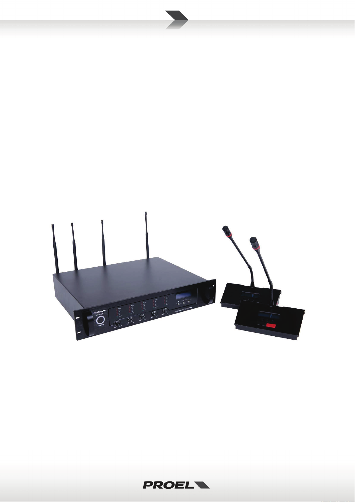
WCS1000
Wireless Conference System
USER’S MANUAL
96MAN00107-R EV. 20/15
ENGLISH
ITALIANO
Page 2

2
DISPOSAL OF OLD ELECTRICAL & ELECTRONIC EQUIPMENT ................................................................. 3
SAFETY INSTRUCTIONS ........................................................................................................................... 3
IN CASE OF FAULT ................................................................................................................................... 3
PACKAGING, SHIPPING AND COMPLAINT .............................................................................................. 3
WARRANTY AND PRODUCTS RETURN .................................................................................................... 3
MAINTENANCE AND DISCLAIMER ......................................................................................................... 4
POWER SUPPLY ...................................................................................................................................... 4
USER’S WARNINGS AND CE CONFORMITY ............................................................................................ 5
INTRODUCTION ...................................................................................................................................... 6
DESCRIPTION .......................................................................................................................................... 6
FEATURES ............................................................................................................................................... 6
WCS1000 RECEIVER UNIT ...................................................................................................................... 6
WCS1000C and WCS1000D TRANSMITTER UNIT ................................................................................... 8
WCS1000CH BATTERY CHARGER ............................................................................................................ 9
IRC14430X3 Li-Ion battery pack ............................................................................................................. 9
SET-UP INSTRUCTIONS ......................................................................................................................... 10
ROOM LAYOUT AND COVERAGE AREA ................................................................................................ 10
WCS1000RX RECEIVER UNIT INSTALLATION ........................................................................................ 10
WCS1000RX RECEIVER UNIT SET-UP .................................................................................................... 11
WCS1000RX AUDIO RF CHANNEL SET-UP ............................................................................................ 13
WCS1000C and WCS1000D INSTALL OR REPLACE THE BATTERY PACK ................................................ 14
WCS1000C and WCS1000D MICROPHONE INSTALLATION .................................................................. 15
WCS1000C and WCS1000D TRANSMITTER UNIT SET-UP .................................................................... 15
CONFERENCE SYSTEM AUDIO CHECK .................................................................................................. 16
WCS1000RX LOCK & UNLOCK .............................................................................................................. 16
TECHNICAL SPECIFICATION .................................................................................................................. 17
FIG.1 ..................................................................................................................................................... 37
FIG.2 ..................................................................................................................................................... 37
FIG.3 ..................................................................................................................................................... 38
FIG.4 ..................................................................................................................................................... 38
Page 3

3
DISPOSAL OF OLD ELECTRICAL & ELECTRONIC EQUIPMENT
This marking shown on the product or its literature, indicates that it should not be disposed with
other household wastes at the end of its working life. To prevent possible harm to the enviroment
or human health from uncontrolled waste disposal, please separate this from other types of
wastes and recycle it responsibly to promote the sustainable reuse of material resources.
Household users should contact either the retailer where they purchased this product, or their
local government office, for details of where and how they can take this item for environmentally safe
recycling. Business users should contact their supplier and check the terms and conditions of the purchase
contract. This product should not be mixed with other commercial wastes for disposal.
SAFETY INSTRUCTIONS
• CAUTION - Before using this product read carefully the following safety instructions. Take a look of
this manual entirely and preserve it for future reference. When using any electric product, basic
precautions should always be taken, including the following:
• To reduce the risk, close supervision is necessary when the product is used near children.
• Protect the apparatus from atmospheric agents and keep it away from water, rain and high humidity
places.
• This product should be site away from heat sources such as radiators, lamps and any other device
that generate heat.
• Care should be taken so that objects and liquids do not go inside the product..
• The product should be connected to a power supply only of the type described on the operating
instructions or as marked on the product.
IN CASE OF FAULT
• In case of fault or maintenance this product should be inspected only by qualified service personnel
when:
Liquids have spilled inside the product.
The product has fallen and been damaged.
The product does not appear to operate normally or exhibits a marked change in performance.
• Do not operate on the product, it has no user-serviceable parts inside.
• Refer servicing to an authorized maintenance center.
PACKAGING, SHIPPING AND COMPLAINT
• This unit package has been submitted to ISTA 1A integrity tests. We suggest you control the unit
conditions immediately after unpacking it.
• If any damage is found, immediately advise the dealer. Keep all unit packaging parts to allow
inspection.
• Proel is not responsible for any damage that occurs during shipment..
• Products are sold “delivered ex warehouse” and shipment is at charge and risk of the buyer.
• Possible damages to unit should be immediately notified to forwarder. Each complaint for
manumitted package should be done within eight days from product receipt.
WARRANTY AND PRODUCTS RETURN
• Proel products have operating warranty and comply their specifications, as stated by manufacturer..
• Proel warrants all materials, workmanship and proper operation of this product for a period of two
years from the original date of purchase. If any defects are found in the materials or workmanship or
if the product fails to function properly during the applicable warranty period, the owner should
inform about these defects the dealer or the distributor, providing receipt or invoice of date of
purchase and defect detailed description. This warranty does not extend to damage resulting from
improper installation, misuse, neglect or abuse. Proel S.p.A. will verify damage on returned units,
Page 4

4
and when the unit has been properly used and warranty is still valid, then the unit will be replaced or
repaired. Proel S.p.A. is not responsible for any “direct damage” or “indirect damage” caused by
product defectiveness.
MAINTENANCE AND DISCLAIMER
• Clean only with dry cloth.
• Proel products have been expressly designed for audio application, with signals in audio range (20Hz
to 20kHz). Proel has no liability for damages caused in case of lack of maintenance, modifications,
improper use or improper installation non-applying safety instructions.
• Proel S.p.A. reserves the right to change these specifications at any time without notice..
• Proel S.p.A. declines any liability for damages to objects or persons caused by lacks of maintenance,
improper use, installation not performed with safety precautions and at the state of the art.
POWER SUPPLY
• This apparatus should only be connected to power source type specified in this owner’s manual or on
the unit.
• If the supplied AC power cable plug is different from the wall socket, please contact an electrician to
change the AC power plug.
• Hold the plug and the wall outlet while disconnecting the unit from AC power.
• If the unit will not be used for a long period of time, please unplug the power cord from AC power
outlet.
• To avoid unit power cord damage, please do not strain the AC power cable and do not bundle it.
• In order to avoid unit power cord damage, please ensure that the power cord is not stepped on or
pinched by heavy objects.
Page 5
5
USER’S WARNINGS AND CE CONFORMITY
TABLE OF THE AUTHORIZED FREQUENCIES FOR THE WCS1000 WIRELESS CONFERENCE SYSTEM IN EUROPE
WCS1000C / WCS1000D TRANSMITTING FREQUENCIES*
744.000 - 744.750
745.000 - 764.750
AL AT BA BE BG CH CY CZ DK EE ES GB HR
Individual license required
GE
NOT IMPLEMENTED
IN ALL COUNTRIES THE USE OF WIRELESS MICROPHONES SYSTEMS IS SUBJECT TO ANY TELEVISION AND
CONSULT LOCAL OR NATIONAL RADIO SPECTRUM AUTHORITIES FOR INFORMATION ON POSSIBLE
• Changes or modifications not expressly approved by PROEL S.p.A. could void your authority to
operate the equipment.
LICENSING INFORMATION:
• Frequency Range of WCS1000: 744.000 – 764.750 MHz, 422.400 – 439.400 MHz, please read the
technical specification for detailed information about the ranges usage.
• A ministerial license may be required to operate this equipment in certain areas. The use of this
professional wireless microphone equipment in some countries could be intended for professional
use, so the licensability depends on the country it operates. Proel suggests the user to contact the
appropriate telecommunications authority concerning proper licensing.
• This equipment may be capable of operating on some frequencies not authorized in your country.
Please contact your national authority to obtain information on authorized frequencies for wireless
microphone products in your region.
• Licensing of professional wireless microphone equipment is the user’s responsibility, and licensability
depends on the user’s classification and application, and on the selected frequency.
• The product is in compliance with Directive LVD 2006 / 95 / EC as stated in EN 60065 and EN 62479
standard.
• PROEL S.p.A hereby, declares that this wireless microphone system complies with the essential
requirements and other relevant provisions of Directive R&TTE 1999 / 5 / EC as stated in EN 3004221; EN 300422-2; EN 301489-1; EN 300489-9 standard.
• The full and detailed declaration of conformity can be downloaded from the web site:
www.proel.com
UPDATED WITH REFERENCE TO ERC-REC 70-03E DOCUMENT DATED FEBRUARY 07 2014
COUNTRY CODE
HU LV IS IE LI LU ME MK MD NL PT RO RS
SE SI SK TR
DE FI FR GR IT LT MT NO PL RU UA
BROADCAST TRANSMISSION
RESTRICTIONS OR NECESSARY AUTHORIZATIONS BEFORE USING THIS SHORT RANGE DEVICE.
*Note: both apparatus use also 422.400-439.400 with FSK modulation and less than 10% duty cycle for room
data transmission controls. In some countries this band has further limitation, so check the national radio
spectrum authority where the apparatus will be installed and set the room data in the proper range.
Individual license required
and Limited implementation
Page 6

6
INTRODUCTION
TIP, HOW TO SET THE OPTIMAL LEVELS: to set the optimal level for each transmitter follow in
a) Set the VOL knob of the channel at minimum.
Thank you for choosing this PROEL product and for your trust in our brand, synonymous of professionalism,
accuracy, high quality and reliability. All our products are CE approved and designed for continuous use in
professional systems.
DESCRIPTION
The WCS1000 Wireless Conference System provides advanced technology, ease of use and flexibility in a full
modular setup. WCS1000 system offers reliability, intuitive operation and versatility: it can be perfectly
integrated into any meeting rooms without additional wiring and it’s the ideal choice for mobile conference
systems or for small-to-medium scale fixed systems
WCS1000 system features 5 units:
• WCS1000RX wireless system receiver unit.
• WCS1000C chairman transmitter unit.
• WCS1000D delegate transmitter unit.
• WCS1000CH battery charger for 16 Li-Ion battery packs.
• IRC14430X3 Li-Ion battery pack (to supply the WCS1000C and WCS1000D units).
Each system can handle up to 256 WCS1000D delegate units (with up to 4 units that can be used
simultaneously) plus one WCS1000C chairman unit.
FEATURES
Up to 256 wireless microphone units in one system, 5 microphone units (1 chairman, 4 delegates)
can be turned on at the same time.
Operating Modes: LIMIT 1-4, FIFO 1-4, Chairman Only.
Microphone units operates with Li-Ion rechargeable batteries, for approximately 8 hours of
continuous speech or 30 hours in standby.
Wireless communication system eliminates the need of wired connections, so the installation can be
done easily and quickly without cumbersome arrangements.
Multi-channel high UHF band and intermediate UHF band frequency selective filtering able to
eliminate RF interference signal.
Acoustic feedback eliminating technology for reducing the ricks of feedbacks from the loudspeakers.
Multiple noise detecting circuit and TONE-LOCK system for a strong anti-jamming function.
Free open space operation distance up to 100 meters, 60 meters are usually guaranteed in typical
closed environment.
WCS1000 RECEIVER UNIT
See FIG. 1 at page 37.
1. POWER
On/off switch: press and hold for two seconds to switch on or off the receiver.
2. RF / AUDIO LEVEL INDICATORS
The first channel (C) is for chairman microphone, the following four channels (D1, D2, D3, D4) are for
delegate microphones. On each LED bar the first green LED indicates that the receiver is receiving a radio
signal from a transmitter unit on that channel. If the LED is off, check if the transmitter is off or set as
ready or set for another RM (see ROOM function further). The red LEDs show the audio signal level from
the microphone unit.
sequence these instructions.
Page 7
7
b) Press TALK button on the transmitter.
c) Speaking loudly on the microphone use the transmitter unit’s and buttons to set the
to avoid feedbacks.
TIP, HOW TO AVOID DISTORTION: the D1-4 VOL knobs set the output level of each receiver channel.
the second place.
level.
d) The optimal signal level is when all the LED bar are on except the last PEAK LED.
e) Finally raise up the receiver VOL knob in order to have the right sound level in the room but
3. C VOL
Volume knob of chairman microphone.
4. D1 VOL
Volume knob of delegate 1 microphone.
5. D2 VOL
Volume knob of delegate 2 microphone.
6. D3 VOL
Volume knob of delegate 3 microphone.
7. D4 VOL
Volume knob of delegate 4 microphone.
To avoid too high or distorted signals (PEAK LED on) is a good practice to reduce the level on the D14 transmitter using button at first and setting the respective D1-4 VOL knob on the receiver in
8. DOWN button
Pressing this button the frequencies used by each channel are shown in sequence: Room, D4, D3, D2, D1
delegates and C chairman, then back to mode status display. If it’s pressed after the SET button, it scrolls
between the available option (see set-up instructions).
9. SET
Press it to select the receiver’s option to be set (see set-up instructions). When pressed, the selected
option flashes for about 5 seconds: if within this time neither DOWN or UP button is pressed, the
receiver exit from the setting status.
10. UP button
Pressing this button the frequencies used by each channel are shown in sequence: C chairman, D1, D2,
D3, D4 delegates and Room, then back to status display. If it’s pressed after the SET button, it scrolls
between the available option (see set-up instructions).
11. DISPL AY
Displays current setting status and channel numbers.
12. ANT DATA
Socket for data antenna. Connect here the DATA antenna.
Page 8

8
13. DATA
TIP, HOW TO MUTE TEMPORARILY THE CONVERSATION: the MUTE button is useful if the
Data connection for optional device.
14. 12-15VDC 2A
Socket for the AC/DC adaptor: use only the adaptor supplied with the system.
15. BALANCED OUTPUT
Balanced audio output, to be connected to the audio system and used with long cable runs.
16. UNBALANCED OUTPUT
Unbalanced audio output that can be used as an alternate or additional output.
17. ANT B
Socket for first RF antenna for DELEGATE microphone units. Connect here the first B antenna.
18. ANT B
Socket for second RF antenna for DELEGATE microphone units. Connect here the second B antenna.
19. ANT A
Socket for RF antenna for CHAIRMAN microphone unit. Connect here the A antenna.
WCS1000C and WCS1000D TRANSMITTER UNIT
See FIG. 2 at page 37.
1. MICROPHONE
Microphone capsule with a hyper-cardioid unidirectional pattern.
2. TALK LIGHT
This indicator is on when microphone is active: the display shows “CH-__-SPEAK”. The indicator is off
when the transmitter is off or it’s ready: in this case the display shows “CH-__-REA DY ”.
3. DOWN button
Use this button to reduce the unit’s microphone level or to edit an option selected using the SET button.
4. UP button
Use this button to increase the unit’s microphone level or to edit an option selected using the SET button.
5. MUTE / SET button
When the transmitter is active and the display shows “CH-__-SPEAK”, if this button is held down it mutes
the microphone: the display shows “CH-__-MU TE”. When it’s released, the microphone is active again
“CH-__-SPEAK”. Keep this button pressed while the transmitter unit is turned on to set the transmitter
parameters (see set-up instructions).
chairman/delegate wants to mute temporarily the conversation without losing his/her priority, so
keeping the priority even if the microphone is muted.
6. TALK button
Press this button to talk: the microphone is active, the TALK light is on and the display shows “CH-__SPEAK”.
Press this button again to turn off the microphone: the TALK light is off and the display shows “CH-__REA DY”.
7. PRIORITY button
This button is present only on the WCS1000C chairman transmitter unit: when pressed the chairman
takes its priority over all the delegates units, turning all the other microphones off. The chairman can talk
until he/she presses again the TALK button to turn off his/her microphone (see set-up instructions).
Page 9
9
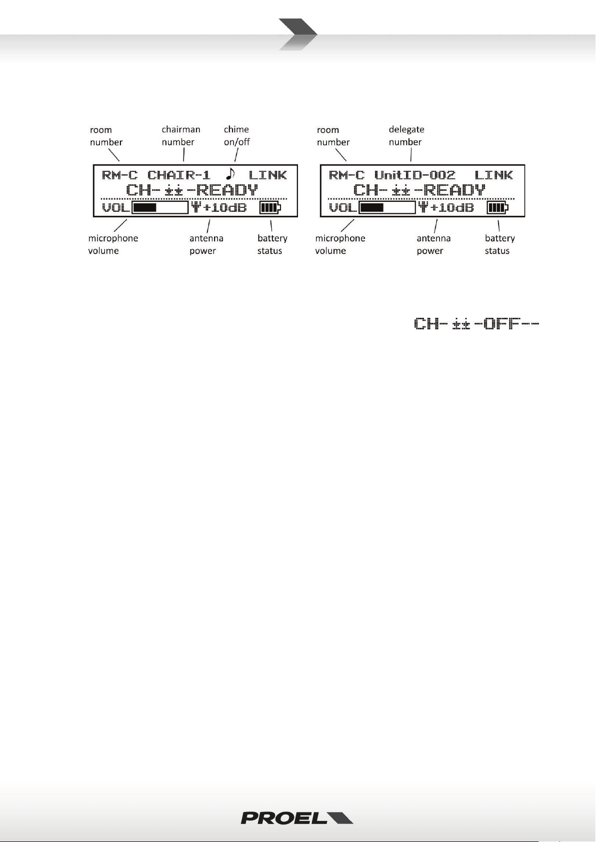
8. DISPLAY
The Display shows current mode status, room number, unit number, channel number, volume setting,
battery status:
9. POWER button
To turn on the unit press and hold this button until the display appears: if that doesn’t happen, replace
the battery pack with a new one fully charged.
To turn off the unit press and hold again the button until the display shows:
If the MUTE/SET button is held down when the unit is switched on, then it enters in setting mode (see
set-up instructions).
If the UP button is held down when the unit is switched on, the transmitter operates as FREE from the
receiving unit: this mode is usually selected only for servicing operation. In order to set back the standard
LINK operation turn the unit off and on again.
.
WCS1000CH BATTERY CHARGER
See FIG. 3 at page 38.
The battery charger operates with an universal input voltage (100V-240V~) and it can charge up to 16 lithium
battery packs (use only the IRC14430X3 type supplied with the microphone units). Its internal intelligent
charging management circuit protects Li-Ion batteries from excessive temperature and charging. It is hosted
in a case with extendable handle and castors for easy transport.
1. CHARGE LED
This is the charging status LED: it is RED during the battery pack charging, it is GREEN when the battery
pack is fully charged and ready to be installed in the transmitter.
2. BATTERY HOLDER
Insert the battery pack to be recharged in any holder. Be sure to insert it respecting the right polarity. A
fully discharged pack requires about 2h to be fully recharged.
3. POWER INDICATOR
It ’s on when the charger is active.
4. POWER ON/OFF SWITCH
To turn on and off the charger.
5. AC~ SOCKET
Here’s where you plug in your mains supply cord. Be sure that your device is turned off before you plug
the mains supply cord into an electrical outlet.
IRC14430X3 Li-Ion battery pack
See FIG. 4 at page 38.
The supplied Li-Ion battery pack features an excellent safety performance, lightweight, high capacity ratio
Page 10
10
and less chance for electrolyte leakage. It usually provided more than 300 charge cycles.
IMPORTANT: The battery contains Perchlorate Material – special handling may apply, it should
harm to the environment or human health from uncontrolled waste disposal, please separate
1. Battery detach/lock button
2. Negative pole
3. Positive pole
not be disposed with other household wastes at the end of its working life. To prevent possible
this from other types of wastes and recycle it.
SET-UP INSTRUCTIONS
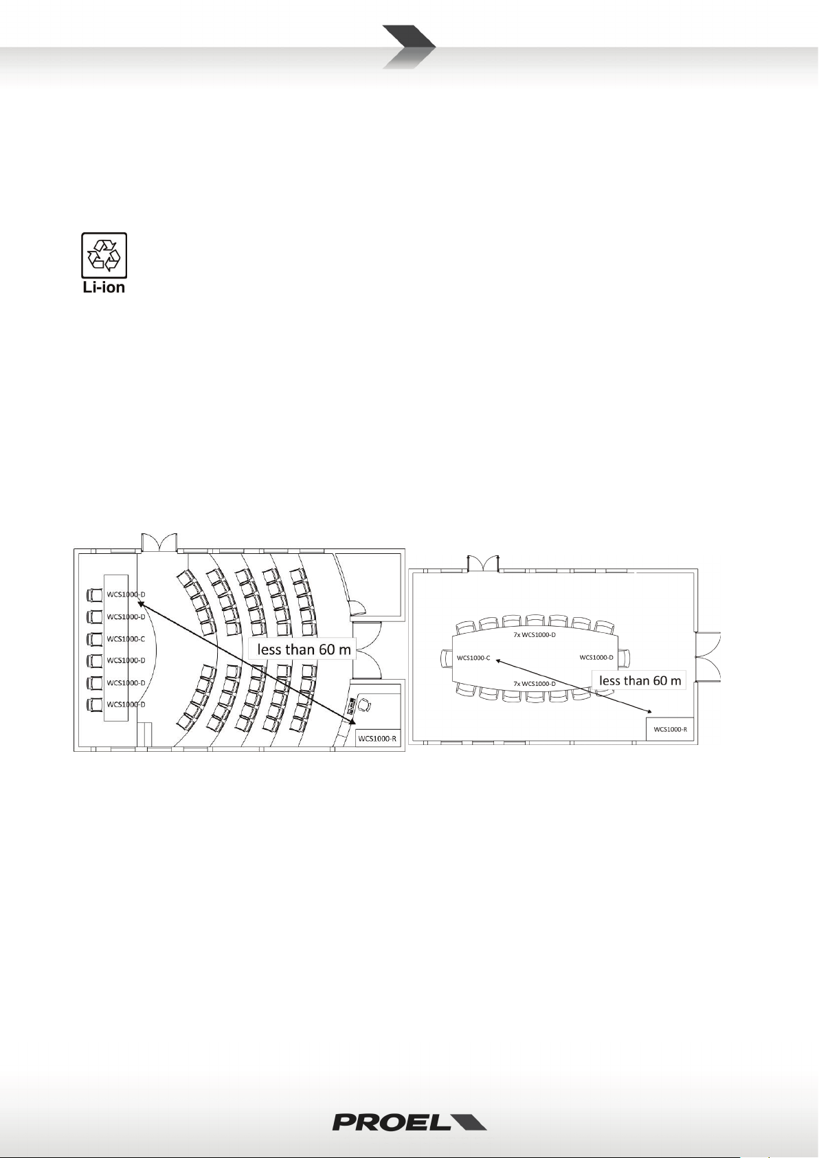
ROOM LAYOUT AND COVERAGE AREA
Choose the receiver location checking the real coverage area of conference room (usually coverage area of
conference room is smaller than the conference room area).
Typically in a closed space the maximum distance of any transmitter unit from the receiver unit must be less
than 60 m (200 ft). We suggest to check carefully the receiver installation to find the best location: wall
reflections, rack mounting and interference from other electronic equipment or metal furniture can influence
the RF signals and, consequently, the features of the WCS1000 system.
Example of conference room: Example of meeting room:
WCS1000RX RECEIVER UNIT INSTALLATION
The WCS1000RX receiver unit must be installed on a table or in 19” rack and the audio output must be
connected to the conference room audio system.
Keep the receiver away from high-power and strong radiation equipment or it may influence the system
receiving performance.
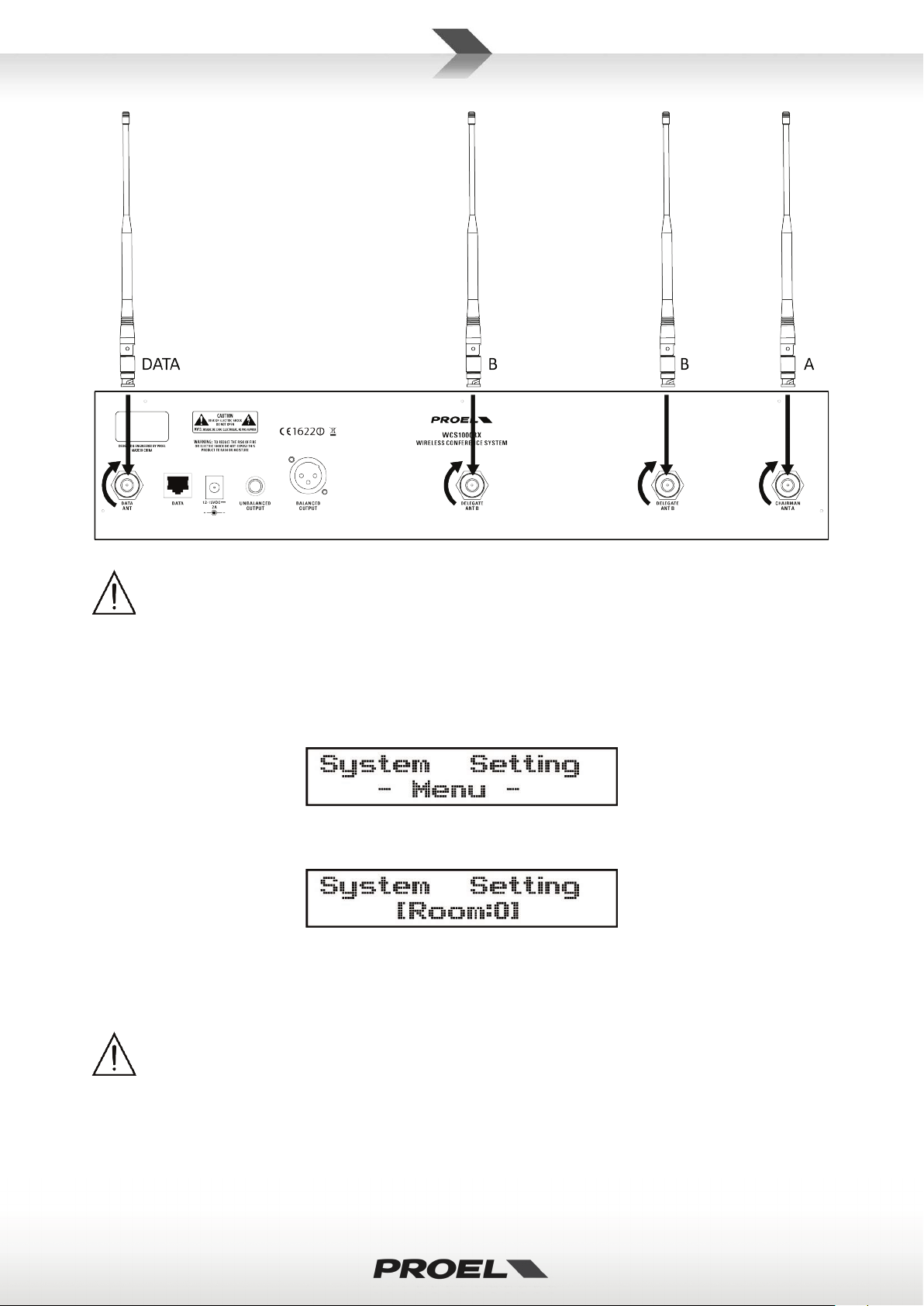
There are 4 antennas to be connected to receiver unit:
1 x ANT DATA: antenna for control DATA, i t must be connected to DATA ANT connector.
1 x ANT A + 2 x ANT B: antenna for CHAIRMAN and DELEGATE microphone units, they must be connected to
ANT A and ANT B connectors respectively.
Page 11
11
IMPORTANT: the different receiver antennas must be connected in correct positions or the system
When choosing a control channel try to avoid channels used by other RF apparatus or other
channel.
In the majority of the UE countries the range for remote controls SRD is 433.050-434.790 MHz,
spectrum authority to set a proper frequency channel.
will work properly.
WCS1000RX RECEIVER UNIT SET-UP
WCS1000RX receiver’s most used parameters can be set in the STANDARD menu, while more in-deep
parameters can be set in the SYSTEM SETTING menu.
To visualize the SYSTEM SETTING menu press and hold the SET button while powering up the receiver. The
display will show:
Release the SET button and the display will show the Room setting:
Pressing the UP and DOWN buttons you can choose the Room control channel within the range of 0-9,
A-F. This is the RF channel used by the system to exchange control data between the receiver and the
microphone units. Each channel corresponds to a frequency and a free frequency channel must be selected.
WCS1000 systems in adjacent rooms.
The receiver and all the transmitter units must be set always on the same room CONTROL
that corresponds to the Room channels B and C. In any case please consult your national
Page 12
12
TIP: this function is useful to reduce the number of delegate RF channels that can be active
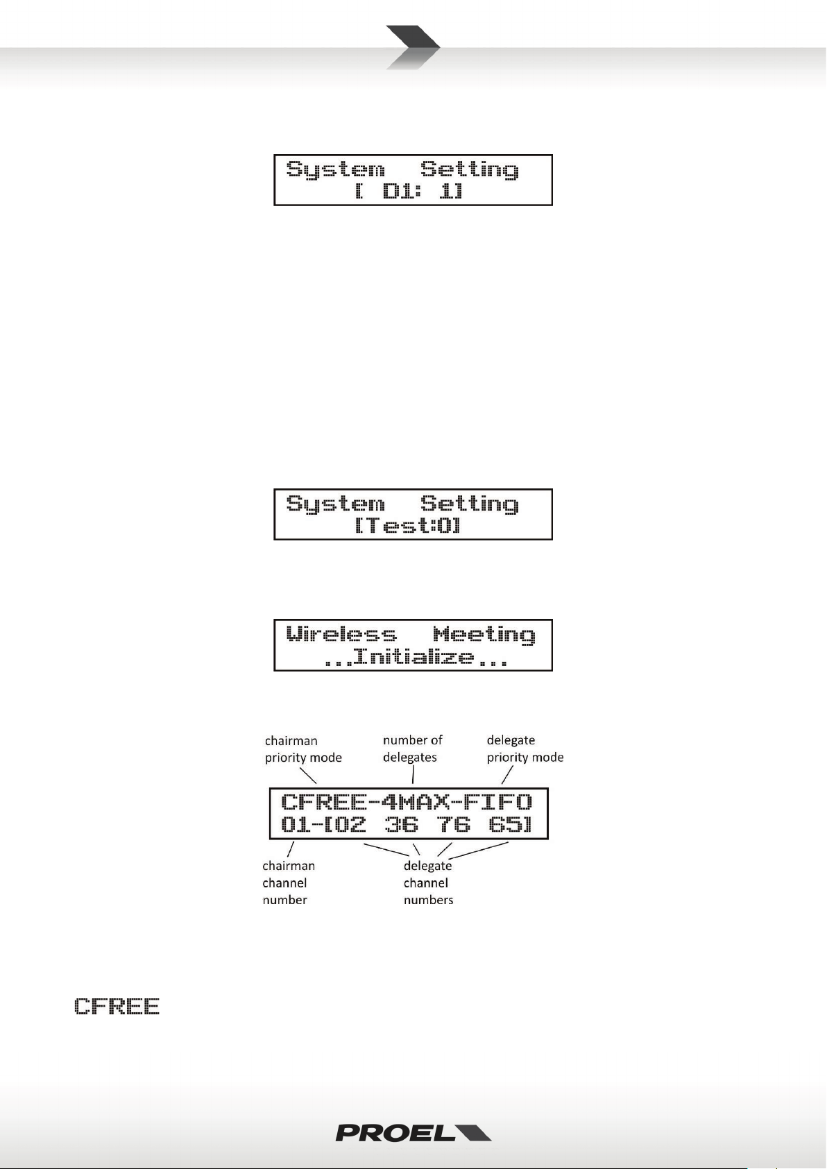
Pressing again the SET button the display shows the Delegate RF activation setting:
Pressing the UP and DOWN buttons you can enable [1] or disable [0] a delegate unit RF channel. Pressing
again the SET button you can also select RF channels D2 or D3. D4 cannot be disabled because at least one
channel must be active.
simultaneously. For example, in case of two adjacent meeting rooms using two WCS1000 system, if
you reduce the active channels of both systems to two each they can both operate in a more
reliable way.
NOTE: regardless of how many RF channels are active, the maximum number of delegate units that
can be used in a WCS1000 system is always 256, see also the delegates set-up operation further in
this manual.
Pressing again the SET button the display shows the Test setting:
This is a FACTORY mode used for the device test.
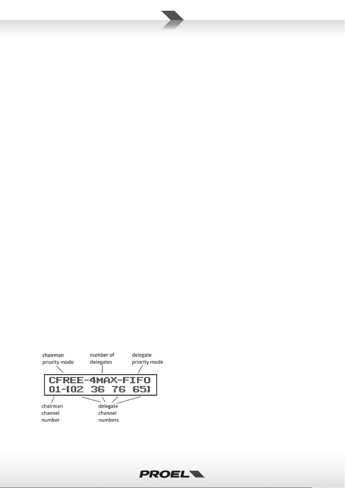
Pressing again the POWER button the receiver will be initialized and enter the STANDARD operating mode:
The display will show the last set-up status (the following is an example):
This is the STANDARD menu and the most used parameters can be set here.
Pressing the SET button one time is possible to set the CHAIRMAN PRIORITY MODE: by pressing UP or
DOWN button you can select CFREE or CONLY.
: in this mode, when the chairman presses the PRIORITY button all delegates are shut down and
he has the priority to speak, but any delegate can speak again together with the chairman just by pressing his
TALK button.
Page 13

13
The chairman and delegate channels operates in different ranges, so there is no interference
: when the chairman presses the PRIORITY button all delegates are shut down and he has the
priority to speak, but in this case the delegates cannot speak until the chairman gives the word to them by
releasing the priority (pressing the TALK button).
Pressing the SET button two times it’s possible to set the maximum NUMBER OF ACTIVE DE LEGATES that can
speak simultaneously. By pressing UP or DOWN button the number of delegates can be set from 1 to 4:
Pressing the SET button three times is possible to set the DELEGATE PRIORITY MODE. By pressing UP or
DOWN button this mode can be set as LIMIT or as FIFO:
: with the delegate priority set as LIMIT, once the maximum NUMBER OF ACTIVE DELEGATES
has been reached, no other delegates can speak until one or more active delegates shut off their
microphone. For example, with 1MAX LIMIT setting only one delegate can speak at the time and no other
delegate can speak until he/she has finished to talk and has released the TALK button.
: with the delegate priority set as FIFO, once the maximum NUMBER OF ACTIVE DELEGATES has
reached, the next delegate activating the microphone automatically shuts off the microphone of the first
active delegate, so the priority is like a sequence of First In / First Out. For example with 1MAX FIFO setting
only one delegate can speak at the time and any other delegate can shut him/her off and talk just by pressing
the TALK button.
WCS1000RX AUDIO RF CHANNEL SET-UP
When the WCS1000RX is turned ON, the last audio RF channel setting appears on the display, for example:
The first number is the chairman audio RF channel while the following numbers, within the square brackets,
are the delegate audio RF channels. The chairman channel operates in the 744-745MHz range, the delegate
channels operate in the 745-765MHz range, with a channel separation of 250KHz.
between them. However all delegate channels operate in the same range, so the channel
numbers must be different to avoid interferences.
To set the audio RF channel channels you can operate manually or use the auto-scan function.
Manual setting
Press SET key one or several times until the channel number is flashing. Then press UP or DOWN
button to select the channel and then press SET to save it or wait about 3 seconds until the system has saved
the setting automatically (the number will stop flashing).
Auto-scan setting
Press SET key one or several times until the channel number is flashing and then press and hold the SET key
until the display shows the symbol ---. Release the key and the system will scan all audio channel and
automatically select the best one. 4 channels are available for chairman (00-03) and 80 channels are available
for delegates (00-79).
Page 14

14
In order to select the correct frequency for each channel and to avoid interferences, we suggest to use the
TIP: if there are other radio-frequency transmitters in the same coverage area where the WCS1000
IMPORTANT NOTE: the transmitting channels are set on the receiver unit only. The WCS1000RX
channel on WCS1000RX, further in the manual you can see how to set it on transmitter units.
IMPORTANT: be careful to respect always the polarity marked inside the battery inlet.
corrosion of the battery contacts.
following procedure:
1) Set the first delegate channel in the receiver unit. Then switch on the first delegate microphone and
press the TALK button, leaving the unit active.
2) Set the second delegate channel in the receiver unit. Then switch on the second delegate
microphone and press TALK button, leaving the unit active.
3) Repeat the procedure for delegate channel three and four.
system is used, we suggest to turn them on when setting the RF channels using auto-scan, so the
system will choose frequencies that are truly free.
manages the RF channels and tell to the chairman and delegate units which RF channel they have
to use. To do that WCS1000RX uses the room control channel and this is why it’s so important that
the room control channel is the same for all units. See above about how to set the room control
WCS1000C and WCS1000D INSTALL OR REPLACE THE BAT TERY PACK
When the display on WCS1000C or WCS1000D units shows a low battery level or when the battery pack is
completely exhausted, replace the battery pack as follows:
Remove the batteries if you don’t use the microphone for a long period of time: this will avoid the
Page 15

15
WCS1000C and WCS1000D MICROPHONE INSTALLATION
The receiver and all the transmitter units of the same conference system must be set always on
All microphone ID in one system must be different: if different units have the same ID number,
To install the microphone gooseneck into the base, insert it to the base connector, then turn it until it slides
slightly into the connector. When it is inserted completely (be careful to not force it!), screw the security ring
clockwise:
To remove the gooseneck unscrew the security ring before disconnecting.
WCS1000C and WCS1000D TRANSMITTER UNIT SET-UP
Press the POWER button to switch the microphone unit while keeping pressed the MUTE button: the
microphone unit enters in SETTING mode with the first parameter flashing. You can select the next
parameter by pressing again the MUTE button and you change a parameter value using the and
buttons. If you press again POWER button or wait 9 secs the microphone unit will exit from setting mode.
The parameter are:
This is the room control channel in the range of 0-9,A-F. E ach channel corresponds to a frequency and
you must set the same frequency channel previously set on the WCS1000RX receiver.
the same Control Room Channel.
Chairman microphone unit ID setting: this number can be set from 0-9, A-F for a total 16 ID
chairman units in the system. However, in a typical conference system there is only one chairman.
Delegate microphone unit ID setting: this number can be set from 0-255, for a maximum
256 ID different delegate units in the conference system.
the system will not work properly.
Chime of chairman microphone: when the chairman presses the PRIORITY button, the system playa a
chime sound to advise all delegates that he/she is taking the word. Setting this parameter as
sound is played.
no chime
Page 16

16
CONFERENCE SYSTEM AUDIO CHECK
If you had followed all previous set-up instructions, your conference system should be set to operate
properly. At this point finally you have to check the audio system following these instructions.
Connect the receiver WCS1000RX to the conference room’s audio system.
Set the level controls of your audio system at mid position or “0” level.
Then turn on the WCS1000RX receiver and set all the level knobs to minimum.
Press the talk button on the transmitter unit and speak loudly at the microphone.
Set the VOL level using the buttons on the transmitter unit
Meanwhile check the optimal level on the LED bar: all LED light except the PEAK LED.
Typically the VOL bar on the transmitter display should be placed in the ¼ to ¾ range.
Finally raise up the VOL knob on the WCS1000RX receiver and set the volume to an
audible e comfortable level, avoiding feedback noise. Typically the knob should be stay in
the ½ to ¾ range.
Repeat this procedure for each transmitter and finally check the whole system with the maximum number of
5 microphone active: if there is any audio feedback, reduce the main level of the audio system.
WCS1000RX LOCK & UNLOCK
After the system is set-up properly, it could be useful to lock all the buttons on the receiver in order to avoid
inappropriate operation from unauthorized person.
LOCKING: Press and hold the SET button first, then press UP button, the display will show:
UNLOCKING: Press and hold the SET button first, then press DOWN button, the display will show:
Page 17

17
TECHNICAL SPECIFICATION
WCS1000RX – Conference System UHF Receiver
RF Channels
80 frequency preset for delegate audio UHF band
16 frequency preset for control room data UHF band
RF Frequency Band
Delegate audio UHF: 745.000 - 764.750 MHz
national limitation)
RF Receiver Type
PLL UHF Synthesized
RF Power
Data: max 10 mW
RF Modulation type
Data: FSK (duty cycle less 10%)
RF Sensibility
-105 dBm / 12 dB SINAD
RF Image/Spurious Rejection
> 70 dB
RF Interference Rejection
> 70 dB
RF Frequency Stability
± 0.005% (-10 ÷ +40 °c)
THD Distortion
< 0.8%
S/N Ratio
> 90 dB
Dynamic Ratio
> 105 dB
Frequency Response
50 Hz – 15 KHz (±3 dB)
nominal audio output
0 dBu
Power Supply
12-15 VDC 2 A
Dimensions (WxDxH)
485 ×355 × 85 mm
Weight
7.0 Kg
WCS1000C & WCS1000D – Microphone unit UHF Transmitter
RF Channels
80 frequency preset for delegate audio UHF band
16 frequency preset for control room data UHF band
RF Frequency Band
Delegate audio UHF: 745.000 - 764.750 MHz
limitation)
RF Power
Audio: max 10 mW
Data: max 10 mW
Modulation method
Audio: FM (F3E)
Data: FSK (duty cycle less 10%)
RF Max deviation
60 KHz
RF Frequency Stability
± 0.005% (-10 ÷ +40 °c)
Spurious Emission
under limits EN 300422
Frequency Response
50 Hz – 15 KHz (±3 dB)
Microphone type
Electrect hyper-cardioid
Power Supply
Lithium rechargeable battery pack
Dimensions (WxDxH)
170 × 58 × 120 mm
Weight
0.7 Kg
WCS1000CH Battery Charger
Power supply
110 – 240 V~ 50Hz / 60Hz
Consumption
200 W
4 frequency preset for chairman audio UHF band
Chairman audio UHF: 744.000 - 744.750 MHz
Control room data UHF: 422.400-439.400 MHz (see
4 frequency preset for chairman audio UHF band
Chairman audio UHF: 744.000 - 744.750 MHz
Control room data UHF: 422.400-439.400 MHz (see national
Page 18

18
Battery pack type
3.7 VDC Li-Ion rechargeable
Number of Battery pack
16
Max charging current
700 mA
Charging time
2 hours
Dimensions (WxDxH)
620 × 370 × 175 mm
Weight
9 Kg
IRC14430X3 Li-Ion Battery Pack
Rated voltage
3.7 VDC
Discharge current
<
500 mA
Charging current
700 mA
Time of speaking
8 hours
Time of standby
24 hours
Dimensions (WxDxH)
47 × 40 × 12 mm
Weight
54 g
<
>
>
Page 19

19
TRATTAMENTO DEL DISPOSITIVO ELETTRICO OD ELETTRONICO A FINE VITA ..................................... 20
AVVERTENZE PER LA SICUREZZA .......................................................................................................... 20
IN CASO DI GUASTO ............................................................................................................................. 20
IMBALLAGGIO, TRASPORTO E RECLAMI .............................................................................................. 20
GARANZIE E RESI .................................................................................................................................. 20
MANUTENZIONE E LIMITAZIONI D’USO ............................................................................................... 21
ALIMENTAZIONE ................................................................................................................................... 21
AVVERTENZE PER L’UTILIZZO E CONFORMITÀ CE ................................................................................ 22
INTRODUZIONE .................................................................................................................................... 23
DESCRIZIONE ........................................................................................................................................ 23
FEATURES ............................................................................................................................................. 23
WCS1000 UNITÀ RICEVITORE ............................................................................................................... 23
WCS1000C e WCS1000D UNITÀ TRASMETTITORE ............................................................................... 25
WCS1000CH CARICA BATTERIE ............................................................................................................ 26
IRC14430X3 pacco batteria Li-Ion ........................................................................................................ 27
ISTRUZIONI DI IMPOSTAZIONE ............................................................................................................. 28
DISPOSIZIONE IN AMBIENTE E AREA DI COPERTURA .......................................................................... 28
INSTALLAZIONE DEL RICEVITORE WCS1000RX ..................................................................................... 28
CONFIGURAZIONE DEL RICEVITORE WCS1000RX ................................................................................ 29
IMPOSTAZIONE DEI CANALI AUDIO RF SU WCS1000RX....................................................................... 31
INSTALLARE O SOSTITUIRE LE BATTERIE SU WCS1000C/D .................................................................. 32
INSTALLAZIONE DEL MICROFONO SU WCS1000C/D ........................................................................... 32
IMPOSTAZIONE DELLE UNITÀ TRASMETTITORE WCS1000C/D ............................................................ 32
CONTROLLO AUDIO DEL SISTEMA PER CONFERENZA .......................................................................... 33
BLOCCO E SBLOCCO DEL WCS1000RX .................................................................................................. 34
SPECIFICHE TECNICHE .......................................................................................................................... 35
FIG.1 ..................................................................................................................................................... 37
FIG.2 ..................................................................................................................................................... 37
FIG.3 ..................................................................................................................................................... 38
FIG.4 ..................................................................................................................................................... 38
Page 20

20
TRATTAMENTO DEL DISPOSITIVO ELETTRICO OD ELETTRONICO A FINE VITA
Il marchio riportato sul prodotto o sulla documentazione indica che il prodotto non deve essere
smaltito con altri rifiuti domestici al termine del ciclo di vita. Per evitare eventuali danni
all’ambiente si invita l’utente a separare questo prodotto da altri tipi di rifiuti e di riciclarlo in
maniera responsabile per favorire il riutilizzo sostenibile delle risorse materiali. Gli utenti
domestici sono invitati a contattare il rivenditore presso il quale è stato acquistato il prodotto o l’ufficio locale
preposto per tutte le informazioni relative alla raccolta differenziata e al riciclaggio per questo tipo di
prodotto. Gli utenti aziendali sono invitati a contattare il proprio fornitore e verificare i termini e le condizioni
del contratto di acquisto. Questo prodotto non deve essere smaltito unitamente ad altri rifiuti commerciali.
AVVERTENZE PER LA SICUREZZA
• ATTENZIONE - Prima di utilizzare il prodotto, si prega di leggere attentamente le seguenti istruzioni
per la sicurezza. Prendere visione del manuale d’uso e conservarlo per successive consultazioni.
Durante l’uso di un prodotto elettrico devono essere sempre prese precauzioni di base onde evitare
danni a cose o persone, incluse le seguenti:
• In presenza di bambini, controllare che il prodotto non rappresenti un pericolo.
• Posizionare l’apparecchio al riparo dagli agenti atmosferici e a distanza di sicurezza dall’acqua, dalla
pioggia e dai luoghi ad alto grado di umidità.
• Collocare o posizionare il prodotto lontano da fonti di calore quali radiatori, griglie di riscaldamento e
ogni altro dispositivo che produca calore.
• Evitare che qualsiasi oggetto o sostanza liquida entri all’interno del prodotto.
• Il prodotto deve essere connesso esclusivamente alla alimentazione elettrica delle caratteristiche
descritte nel manuale d’uso o scritte sul prodotto.
IN CASO DI GUASTO
• In caso di guasto o manutenzione questo prodotto deve essere ispezionato da personale qualificato
quando:
Sostanze liquide sono penetrate all’interno del prodotto.
Il prodotto è caduto e si è danneggiato.
Il prodotto non funziona normalmente esibendo una marcato cambio di prestazioni.
• Non intervenire sul prodotto.
• Rivolgersi a un centro di assistenza autorizzato Proel.
IMBALLAGGIO, TRASPORTO E RECLAMI
• L’imballo è stato sottoposto a test di integrità secondo la procedura ISTA 1°. Si raccomanda di
controllare il prodotto subito dopo l’apertura dell’imballo.
• Se vengono riscontrati danni informare immediatamente il rivenditore. Conservare quindi l’imballo
completo per permetterne l’ispezione.
• Proel declina ogni responsabilità per danni causati dal trasporto.
• Le merci sono vendute “franco nostra sede” e viaggiano sempre a rischio e pericolo del distributore.
• Eventuali avarie e danni dovranno essere contestati al vettore. Ogni reclamo per imballi manomessi
dovrà essere inoltrato entro 8 giorni dal ricevimento della merce.
GARANZIE E RESI
• I Prodotti Proel sono provvisti della garanzia di funzionamento e di conformità alle proprie specifiche,
come dichiarate dal costruttore.
• La garanzia di funzionamento è di 24 mesi dopo la data di acquisto. I difetti rilevati entro il periodo di
garanzia sui prodotti venduti, attribuibili a materiali difettosi o difetti di costruzione, devono essere
tempestivamente segnalati al proprio rivenditore o distributore, allegando evidenza scritta della data
di acquisto e descrizione del tipo di difetto riscontrato. Sono esclusi dalla garanzia difetti causati da
Page 21

21
uso improprio o manomissione. Proel SpA constata tramite verifica sui resi la difettosità dichiarata,
correlata all’appropriato utilizzo, e l’effettiva validità della garanzia; provvede quindi alla sostituzione
o riparazione dei prodotti, declinando tuttavia ogni obbligo di risarcimento per danni diretti o
indiretti eventualmente derivanti dalla difettosità.
MANUTENZIONE E LIMITAZIONI D’USO
• Pulire il prodotto unicamente con un panno asciutto.
• I Prodotti Proel sono destinati esclusivamente ad un utilizzo specifico di tipo sonoro: segnali di
ingresso di tipo audio (20Hz-20kHz). Proel declina ogni responsabilità per danni a terzi causati da
mancata manutenzione, manomissioni, uso improprio o installazione non eseguita secondo le norme
di sicurezza.
• Proel S.p.A. si riserva di modificare il prodotto e le sue specifiche senza preavviso.
• Proel S.p.A. declina ogni responsabilità per danni a terzi causati da mancata manutenzione,
manomissioni, uso improprio o installazione non eseguita secondo le norme di sicurezza e a regola
d’arte.
ALIMENTAZIONE
• Il prodotto deve essere connesso esclusivamente alla alimentazione elettrica delle caratteristiche
descritte nel manuale d’uso o scritte sul prodotto.
• Se la spina in dotazione non combacia con la presa, rivolgersi ad un elettricista per far installare una
presa appropriata.
• Quando si scollega l’apparato alla rete tenere saldamente sia la spina che la presa.
• Quando l’unità non viene utilizzata per un periodo prolungato, interrompere l’alimentazione
estraendo la spina dalla presa dell’alimentazione.
• Per evitare danni alla linea d’alimentazione dell’apparato, non mettere in trazione il cavo
d’alimentazione e non utilizzare un cavo attorcigliato.
• Per evitare il danneggiamento del cavo d’alimentazione dell’apparato, assicurarsi che questo non
venga calpestato o schiacciato da oggetti pesanti.
Page 22

22
AVVERTENZE PER L’UTILIZZO E CONFORMITÀ CE
TABELLA FREQUENZE AUTORIZZATE PER IL SISTEMA DI RADIO CONFERENZA WCS1000 IN EUROPA
FREQUENZE DI TRASMISSIONE WCS1000C / WCS1000D*
744.000 - 744.750
745.000 - 764.750
AL AT BA BE BG CH CY CZ DK EE ES GB HR
DE FI FR GR IT LT MT NO PL RU UA
Licenza individuale richiesta e Implementazione Limitata
GE
NON IMPLEMENTATO
IN QUALSIASI NAZIONE L’USO DEI RADIOMICROFONI È SUBORDINATO AD EVENTUALI RADIOTRASMISSIONI
RIFERIRSI SEMPRE ALLE AUTORITA NAZIONALI DELLE FREQUENZE DEL PROPRIO PAESE PER INFORMAZIONI
• Eventuali modifiche di qualsiasi tipo non espressamente autorizzate dalla PROEL S.p.A. possono
annullare il permesso di utilizzo di questo apparecchio.
INFORMATIVA SULLA LICENZA:
• WCS1000 opera nelle bande di frequenze: 744.000 – 764.750 MHz, 422.400 – 439.400 MHz, vedere
le specifiche tecniche per informazioni più dettagliate sulle bande di frequenza usate.
• Una licenza ministeriale è richiesta per l’uso di questo apparecchio. In alcuni paesi potrebbe essere
inteso per uso professionale ed essere soggetto all’ottenimento di una autorizzazione che dipende
dal paese in cui lo si usa. Proel suggerisce all’utilizzatore di contattare l’appropriata autorità alle
telecomunicazioni a proposito della licenza appropriata.
• Questo apparecchio potrebbe essere in grado di funzionare a frequenze non autorizzate nella
nazione e/o regione in cui si trova l’utente, contattare la autorità nazionale alle telecomunicazioni a
riguardo delle frequenze autorizzate per l’uso dei radiomicrofoni nella propria regione.
• Chi usa radiomicrofoni ha la responsabilità di procurarsi la licenza adatta al suo impiego; la
concessione di tale licenza dipende dalla classificazione dell’operatore, dall’applicazione e dalla
frequenza selezionata.
• I Prodotti Proel sono conformi alla direttiva LVD 2006 / 95 / EC, secondo lo standard EN 60065 ed EN
62479.
• Il radio-microfonico Proel è conforme ai requisiti essenziali ed alle altre disposizioni pertinenti
stabilite dalla direttiva R&TTE 1999 / 5 / EC secondo gli standard EN 300422-1; EN 300422-2; EN
301489-1; EN 300489-9.
• La dichiarazione di conformità completa e dettagliata può essere consultata sul sito: www.proel.com
AGGIORNATA CON ERC-REC 70-03° DEL 07 FEBBRAIO 2014
CODICE NAZIONE
HU LV IS IE LI LU ME MK MD NL PT RO RS
SE SI SK TR
TELEVISIVE
SULLE DISPOSIZIONI DELLE FREQUENZE AUTORIZZATE E PER IL LORO USO A NORMA DI LEGGE
*nota: entrambe gli apparati usano anche lo spettro 442.400-439.400 con modulazione FSK e duty cycle <
10% per la trasmissione di controlli. In ITALIA vi è un’ulteriore limitazione di tale banda a 433-434 MHz che
riduce i canali utilizzabili a B o C.
Licenza individuale richiesta
Page 23

23
INTRODUZIONE
SUGGERIMENTO, COME IMPOSTARE I LIVELLI OTTIMALI: per impostare il livello ottimale su ciascun
b) Premere il tasto TALK sul trasmettitore.
Grazie per aver scelto un prodotto PROEL e della fiducia riposta nel nostro marchio, sinonimo di
professionalità, accuratezza, elevata qualità ed affidabilità. Tutti i nostri prodotti sono conformi alle
normative CE per utilizzazione continua in impianti di diffusione sonora.
DESCRIZIONE
Il sistema wireless WCS1000 è la scelta ideale come sistema mobile per conferenze grazie alla massima
flessibilità e affidabilità. Grazie alla semplicità d’uso e alle dimensioni compatte il WCS1000 si integra
perfettamente in qualsiasi meeting room senza la necessità di complessi cablaggi. È la migliore soluzione
senza fili per sale da conferenza medio-piccole.
Il sistema per conferenze WCS1000 è composto da 5 parti:
• WCS1000RX unità principale ricevitore wireless.
• WCS1000C unità trasmittente del presidente (chairman).
• WCS1000D unità trasmittente del delegato (delegate).
• WCS1000CH unità di ricarica per 16 pacchi batteria al Litio.
• IRC14430X3 pacco di batteria al Litio (per alimentare le unità WCS1000C e WCS1000D).
Ogni sistema può gestire fino ad un massimo di 256 unità WCS1000D per delegati (fino a 4 unità per delegati
possono essere usate simultaneamente) più una unità WCS1000C per il presidente.
FEATURES
Fino a 256 unità microfoniche per ogni sistema, 5 unità microfoniche (1 presidente, 4 delegati)
possono essere attive contemporaneamente.
Modi Operativi: LIMIT 1-4, FIFO 1-4, Chairman Only.
Le unità microfoniche sono alimentate da batterie al Litio (Li-Ion) ricaricabili, per una durata
approssimativa di 8 ore di funzionamento continuo con microfono aperto o di 30 ore in standby.
Il sistema di comunicazione wireless elimina la necessità di connessioni cablate e quindi consente
un’installazione semplice e veloce senza complicati cablaggi.
Adotta un sistema di filtraggio selettivo per le frequenze in banda UHF per l’eliminazione delle
interferenza RF.
Implementa una tecnologia per l’eliminazione del rientro acustico (feedback) proveniente dagli
altoparlanti.
100 metri di distanza operativa in spazio aperto, 60 metri nei tipici ambienti al chiuso.
WCS1000 UNITÀ RICEVITORE
Vedi FIG. 1 a pagina 37.
1. POWER
Interruttore On/off: tenerlo premuto per due secondi per accendere o spegnere il ricevitore.
2. RF / AUDIO INDICATORI DI LIVELLO
Il primo canale (C) è per il microfono chairman (presidente), i seguenti quattro canali (D1, D2, D3, D4)
sono per i microfoni dei delegati. In ogni barra LED il primo LED verde indica che il ricevitore sta
ricevendo il segnale radio dall’unità trasmittente su quel canale. Se il LED è spento, controllare se il
trasmettitore è spento o impostato su “READY” o su un’altra “RM” (vedi le funzioni ROOM più avanti). I
LED rossi mostrano il livello del segnale audio della unità microfonica.
trasmettitore seguire le seguenti istruzioni in sequenza:
a) Impostare al minimo la manopola VOL del canale.
Page 24

24
c) Parlando forte al microfono usare i tasti e sull’unita trasmettitore per impostare il
livello.
stanza evitando i feedback.
SUGGERIMENTO, COME EVITARE LA DISTORSIONE: le manopole VOL D1-4 impostano il livelli di
corrispondente manopola VOL D1-4 sul ricevitore.
d) Il segnale ottimale si ha quando si accendono tutti i LED eccetto l’ultimo LED PEAK.
e) Infine alzare la manopola VOL del ricevitore al fine di ottenere un giusto livello sonoro nella
3. C VOL
Manopola Volume del microfono chairman.
4. D1 VOL
Manopola Volume del microfono delegate 1.
5. D2 VOL
Manopola Volume del microfono delegate 2.
6. D3 VOL
Manopola Volume del microfono delegate 3.
7. D4 VOL
Manopola Volume del microfono delegate 4.
uscita di ogni canale del ricevitore. Per evitare segnali eccessivamente alti e distorti (PEAK LED on) è
buona pratica ridurre il livello sui trasmettitori D1-4 usando prima il tasto e impostando poi la
8. tasto GIÙ
Premendo questo tasto sono mostrate in sequenza le frequenze usate da ogni canale: Room, D4, D3, D2,
D1 delegati e C chairman, quindi la visualizzazione standard. Se premuto dopo il tasto S ET, scorre fra le
opzioni di impostazione disponibili (vedi le istruzioni di impostazione).
9. SET
Premerlo per selezionare l’opzione del ricevitore da impostare (vedi le istruzioni di impostazione).
Quando premuto, l’opzione selezionata lampeggia per circa 5 secondi: se entro questo tempo non
vengono premuti i tasti o , il ricevitore esce dalla modalità di impostazione.
10. tasto SU
Premendo questo tasto sono mostrate in sequenza le frequenze usate da ogni canale: C chairman, D1,
D2, D3, D4 delegati e Room, quindi la visualizzazione standard. Se premuto dopo il tasto SET, scorre fra le
opzioni di impostazione disponibili (vedi le istruzioni di impostazione).
11. DISPL AY
Visualizza il corrente stato delle impostazioni e il numero di ogni canale.
12. ANT DATA
Presa per l’antenna dati. Connettere qui l’antenna DATA.
Page 25

25
13. DATA
SUGGERIMENTO, COME CHIUDERE TEMPORANEAMENTE LA CONVERSAZIONE: il tasto MUTE è
Connessione per dispositivi opzionali.
14. 12-15VDC 2A
Presa per l’alimentatore esterno AC/DC: usare esclusivamente l’alimentatore fornito col sistema.
15. BALANCED OUTPUT
Uscita audio bilanciata, da utilizzare per collegare il sistema audio con cavi lunghi.
16. UNBALANCED OUTPUT
Uscita audio sbilanciata che può essere usata in alternativa o in aggiunta all’uscita bilanciata.
17. ANT B
Presa per la prima antenna RF delle unità microfoniche dei delegati. Collegare qui la prima antenna B.
18. ANT B
Presa per la seconda antenna RF delle unità microfoniche dei delegati. Collegare qui la seconda antenna B.
19. ANT A
Presa per l’antenna RF dell’unità microfonica chairman. Collegare qui l’antenna A.
WCS1000C e WCS1000D UNITÀ TRASMETTITORE
Vedi FIG. 2 a pagina 37.
1. MICROFONO
Capsula microfono con caratteristica unidirezionale ipercardioide.
2. LUCE TA L K
Questo indicatore si accendo quando il microfono è attivo: sul display appare “CH-__-SPEA K”. L’indicatore
è spento se il trasmettitore è spento o è pronto: in questo caso il display mostra “CH-__-R EAD Y”.
3. tasto GIÙ
Usare questo tasto per ridurre il livello del microfono o per impostare un’opzione selezionata con il tasto
SE T.
4. tasto SU
Usare questo tasto per aumentare il livello del microfono o per impostare un’opzione selezionata con il
tasto SET.
5. Tasto MUTE / SET
Quando il trasmettitore è attivo e il display mostra “CH-__-SPEAK”, se si tiene premuto questo tasto il
microfono viene silenziato: il display mostra “CH-__-MUTE”. Quando rilasciato, il microfono si riattiva e il
display mostra nuovamente “CH-__-SPEAK”. Te nere premuto questo tasto mentre il trasmettitore viene
acceso per impostare i parametri del trasmettitore (vedi le istruzioni di impostazione).
utile se il chairman/delegato vuole silenziare temporaneamente la conversazione senza perdere la
propria priorità, così da mantenere la priorità anche se il microfono è muto.
6. Tasto TALK
Premere questo tasto per conversare: il microfono è aperto, la luce TALK è accesa e il display mostra “CH__-SPEAK”.
Premere ancora questo tasto per spegnere il microfono: la luce TALK light è spenta e il display mostra
“CH-__-REA DY”.
7. Tasto PRIORITY
Questo tasto è presente solo sull’unità WCS1000C chairman: quando premuto il chairman prende la
Page 26

26
priorità su tutti i delegati, spegnendo tutti gli altri microfoni. Il presidente/chairman potrà parlare finché
terminato il suo intervento premerà il tasto TA LK spegnendo il proprio microfono (vedi anche le istruzioni
di impostazione).
8. DISPLAY
Il display mostra lo stato corrente, numero room, numero unità, numero canale, suoneria, impostazione
del volume, stato della batteria:
9. Tasto POWER
Per accendere l’unità tenere premuto questo tasto finché il display appare: qualora non accadesse,
sostituire il pacco batterie con uno nuovo completamente ricaricato.
Per spegnere l’unità tenere premuto ancora questo tasto finché su display non appare:
.
Se il tasto MUTE/SET è tenuto premuto mentre l’unità viene accesa, essa entra in modalità di
impostazione (vedi le istruzioni di impostazione).
Se il tasto SU è tenuto premuto mentre l’unità viene accesa, il trasmettitore opera libero (FREE)
indipendente dal ricevitore: questo modo viene impostato solo per operazioni di servizio. Per
reimpostare l’impostazione standard LINK spegnere e riaccendere l’unità.
WCS1000CH CARICA BATTERIE
Vedi FIG. 3 a pagina 38.
Il ricarica batterie funziona con l’alimentazione universale (100V-240V~) e può ricaricare fino ad un massimo
di 16 pacchi di batterie al litio (usare solamente le batterie IRC14430X3 fornite con il microfono). Mediante
un controllo di ricarica intelligente le batterie Li-Ion vengono protette da temperatura e carica eccessiva. Il
WCS1000CH è fornito di maniglia estendibile e di ruote per facilitarne il trasporto.
1. LED RICARICA
Questo è il LED dello stato di ricarica: è ROSSO durante la ricarica, diventa VERDE quando il pacco
batterie è completamente ricaricato e pronto per essere installato nel trasmettitore.
2. VANO BATTE RIE
Inserire il pacco batterie da ricaricare in uno dei vani. Assicurarsi di inserirlo rispettando la corretta
polarità. Una batteria completamente scarica richiede circa due ore per essere ricaricata.
3. INDICTORE POWER
È acceso quando il carica batterie è attivo.
4. INTERUTTORE POWER ON/OFF
Per accendere o spegnere il carica batterie.
5. PRESA AC~
Inserire in questa presa il cavo di alimentazione di rete, utilizzando esclusivamente il cavo in dotazione.
Accertarsi che l'apparato sia spento prima di collegarlo alla rete.
Page 27

27
IRC14430X3 pacco batteria Li-Ion
IMPORTANTE: La batteria contiene Perclorato – prendere speciali precauzioni, la batteria non
mediante cassonetto, al termine del suo ciclo
Vedi FIG. 4 a pagina 38.
Le batterie Li-Ion dispongono di eccellenti qualità di sicurezza, leggerezza e capacità, con scarso rischio di
perdite di elettrolita. Sono inoltre in grado di sostenere oltre a 300 cicli di ricarica.
1. Scanalatura per l’estrazione
2. Polo negativo
3. Polo positivo
deve essere smaltita con gli altri rifiuti urbani,
d'utilizzo. Per prevenire possibili danni all'ambiente o alla salute umana derivanti da
un'incontrollata eliminazione dei rifiuti, vi preghiamo di separare la batteria dagli altri rifiuti e
destinarla alla raccolta separata per il suo riciclaggio.
Page 28

28
ISTRUZIONI DI IMPOSTAZIONE
DISPOSIZIONE IN AMBIENTE E AREA DI COPERTURA
Scegliere la posizione del ricevitore controllando la reale area di copertura nella sala conferenze (tipicamente
l’area di copertura nella sala è minore dell’area completa della sala conferenze).
Tipicamente in uno spazio chiuso la massima distanza di ogni trasmettitore dal ricevitore deve essere
inferiore ai 60 m. Suggeriamo di controllare attentamente l’installazione del ricevitore per trovare la migliore
disposizione: riflessioni sui muri, montaggio a rack e interferenze con altri apparecchi o arredi metallici
possono influenzare il segnale RF e, di conseguenza, le prestazioni del sistema WCS1000.
Esempio di sala conferenze: Esempio di sala meeting:
INSTALLAZIONE DEL RICEVITORE WCS1000RX
L’unità ricevitore WCS1000RX deve essere installata su un tavolo o in un rack 19” e l’uscita audio deve essere
collegata al sistema audio della sala conferenze.
Tenere il ricevitore lontano da altri apparati di potenza o in grado di emettere forti radiazioni RF che
potrebbero influenzare le prestazioni di ricezione.
Ci sono 4 antenne da connettere al ricevitore:
1 x ANT DATA: antenna per i dati di controllo, deve essere inserita nel connettore DATA ANT.
1 x ANT A + 2 x ANT B: antenne per la ricezione dei microfoni del CHAIRMAN e dei DELEGATI, devono essere
inserite rispettivamente nei connettori ANT A e ANT B.
Page 29

29
IMPORTANTE: le differenti antenne del ricevitore devono essere connesse nelle corrispondenti
Scegliere un canale di controllo cercando di evitare canali usati da altri apparati RF o altri sistemi
Room.
In Italia la banda di frequenze per i dispositivi SRD di controllo è 433.050-434.790 MHz, che
corrisponde ai canali Room B e C. Usare esclusivamente questi canali.
SUGGERIMENTO: questa funzione è utile per ridurre il numero dei canali RF dei delegati che
posizioni o il sistema non lavorerà correttamente.
CONFIGURAZIONE DEL RICEVITORE WCS1000RX
I parametri più usati del ricevitore WCS1000RX possono essere impostati mediante il menu STANDARD,
mentre i parametri più specialistici possono essere impostati tramite il SYSTEM SETTING menu.
Per visualizzare il SYSTEM SETTING menu tenere premuto il tasto SET mentre si accende il ricevitore. Il
display mostrerà:
Rilasciare il tasto SET e il display visualizzerà l’impostazione Room:
Premendo I tasti UP e DOWN è possibile scegliere il canale di controllo Room tra 0-9, A-F. Questo è il
canale RF usato dal sistema per scambiare I dati di controllo tra il ricevitore e le unità microfoniche. Ogni
canale corrisponde ad una frequenza e deve essere impostata una frequenza libera.
WCS1000 in stanze adiacenti.
Il ricevitore e tutti i trasmettitori devono essere sempre impostati sul medesimo canale di control
Premendo ancora il tasto SET il display mostra l’impostazione per l’attivazione dei canali RF dei delegati:
Premendo I tasti SU e GIÙ è possibile abilitare [1] o disabilitare [0] il canale RF del delegato D1.
Premendo ancora il tasto SET è possibile scegliere i canali RF D2 o D3. D4 non può essere disabilitato perché
almeno un canale deve essere attivo.
possono essere attivi simultaneamente. Per esempio, in caso di due adiacenti meeting room che
usano due sistemi WCS1000, se si riduce a 2 il numero dei canali attivi su ciascun sistema entrambi i
sistemi potranno funzionare in modo più affidabile.
NOTA: a prescindere da quanti canali RF sono attivi, il numero massimo delle unità dei delegati che
possono essere usati in un sistema WCS1000 è sempre 256, vedi più avanti le impostazioni delle
unità dei delegati.
Page 30

30
Premendo ancora il tasto SET il display mostra l’impostazione Test:
Questa è un’impostazione di fabbrica per il test dell’apparecchio, non ha attinenza con l’uso normale.
Premendo il tasto POWER il ricevitore si inizializza ed entra in modalità di uso STANDARD:
Il display visualizzerà lo stato delle ultime impostazioni (le seguenti sono un esempio):
Questo è il menu STANDARD e i parametri più usati possono essere impostati da qui.
Premendo il tasto SET una volta è possibile impostare la priorità dell’unità del presidente (CHAIRMAN
PRIORITY MODE): premendo i tasti SU o GIÙ è possibile scegliere tra CFREE o CON LY.
: con questa modalità, quando il presidente preme il tasto PRIORITY tutti i microfoni dei
delegati vengono spenti ed egli ha la priorità a parlare, ma qualsiasi delegato potrà parlare ancora insieme al
presidente premendo il tasto TALK sulla propria unità.
: con questa modalità, quando il presidente preme il tasto PRIORITY tutti i microfoni dei delegati
vengono spenti ed egli ha la priorità a parlare, ma in questo caso i delegati non potranno parlare finché il
presidente non darà a loro la parola rilasciando la priorità (premendo di nuovo il tasto TALK).
Premendo il tasto SET due volte è possibile impostare il massimo NUMERO DI DELEGATI AT TIVI che possono
parlare simultaneamente. Premendo i tasti SU o GIÙ il numero di delegati può essere impostato da 1 a
4:
Premendo il tasto SET tre volte è possibile impostare la priorità dei delegati (DELEGATE PRIORITY MODE):
premendo i tasti SU o GIÙ è possibile scegliere tra LIMIT o FIFO.
: con la priorità dei delegati impostata su L I MI T, una volta che il massimo NUMERO DI DELEGATI
ATTIVI è raggiunto, nessun altro delegato può parlare fino a quando uno o più dei delegati attivi chiude il
proprio microfono. Per esempio, con impostato 1MAX LIMIT, solo un delegato può parlare alla volta e nessun
altro delegato potrà parlare finché egli non avrà finito la conversazione e lasciato la parola ripremendo il
tasto TALK.
: con la priorità dei delegati impostata su FIFO, una volta che il massimo NUMERO DI DELEGATI
Page 31

31
ATTIVI è raggiunto, il successivo delegato attivando il suo microfono automaticamente chiude il microfono
I canali del chairman e dei delegati operano in differenti bande in modo che non ci sia interferenza
SUGGERIMENTO: se ci sono altri apparati radio trasmettitori nella stessa area di copertura dove il
NOTA IMPORTANTE: i canali di trasmissione sono impostati solo sull’unità ricevente. Il WCS1000RX
spiegato come impostarlo sulle unità
microfoniche di trasmissione chairman e delegato WCS1000C/WCS1000D .
del primo delegato attivo, cosi che la priorità è come una sequenza di “primo ad entrare / primo ad uscire”.
Per esempio, con impostato 1MAX FIFO, solo un delegato può parlare alla volta e qualsiasi altro delegato può
chiudere il suo microfono e prendere la parola semplicemente premendo il tasto TALK.
IMPOSTAZIONE DEI CANALI AUDIO RF SU WCS1000RX
Quando il WCS1000RX è acceso, l’ultima impostazione dei canali audio RF appare sul display, per esempio:
Il primo numero è il canale audio RF del chairman mentre i numeri seguenti, all’interno delle parentesi
quadre, sono I canali audio RF dei delegati. Il canale del chairman opera nella banda 744-745MHz, i canali dei
delegati operano nella banda 745-765MHz, con una separazione tra canali di 250KHz.
fra loro. Tuttavia tutti i canali dei delegati operano nella stessa banda, per ciò i numeri dei canali
dovranno essere diversi per evitare interferenze.
Per impostare i canali audio RF si può operare sia manualmente che usando la funzione auto-scan.
Impostazione manuale
Premere il tasto SET una o più volte fino a che il numero del canale lampeggia. Quindi premere i tasti SU o
GIÙ per selezionare il canale e ripremere SET per salvarlo o attendere 3 secondi affinché smetta di
lampeggiare e si salvi automaticamente.
Impostazione Auto-scan
Premere il tasto SET una o più volte fino a che il numero del canale lampeggia. Quindi premere e tenere
premuto il tasto SET finché sul display appare il simbolo ---. Rilasciare il tasto e il sistema scansionerà tutti I
canali audio RF e automaticamente sceglierà il migliore. Sono disponibili 4 canali per il chairman (00-03) e 80
canali per i delegati (00-79).
Al fine di selezionare la corretta frequenza per ogni canale ed evitare interferenze, suggeriamo di usare la
seguente procedura:
1) Impostare il canale audio RF per il primo delegato. Quindi accendere la prima unità microfono
delegato e premere il tasto TALK, lasciando il microfono attivo.
2) Impostare sul ricevitore il canale audio RF per il secondo delegato. Quindi accendere la seconda unità
microfono delegato e premere il tasto TALK, lasciando il microfono attivo.
3) Ripetere la stessa procedura per i canali dei delegati 3 e 4.
sistema WCS1000 è usato, suggeriamo di accenderli quando si impostano i canali usando l’autoscan, così l’auto-scan sceglierà quelle frequenze che sono realmente libere.
amministra i canali RF e comunica alle unità chairman e delegati quale canale RF essi devono usare.
Per far ciò il WCS1000RX usa il canale di controllo room, per questo è molto importante che il
canale di controllo sia lo stesso per tutte le unità del sistema. Vedi sopra come impostare il canale di
controllo room sul WCS1000RX, mentre più avanti è
Page 32

32
INSTALLARE O SOSTITUIRE LE BATTERIE SU WCS1000C/D
IMPORTANTE: fare attenzione a rispettare sempre la polarità segnata nel vano batteria.
corrosione dei contatti della batteria.
Quando il display delle unità WCS1000C o WCS1000D visualizza un livello di batteria basso o quando le
batterie sono completamente scariche, sostituire il pacco batterie come segue:
Rimuovere le batterie se non si usa il microfono per un lungo periodo di tempo: questo eviterà la
INSTALLAZIONE DEL MICROFONO SU WCS1000C/D
Per installare il microfono flessibile nella base, inserirlo nel connettore della base, quindi ruotarlo finché
scivolerà lievemente nel connettore. Quando lo si sarà inserito completamente (attenzione a non forzarlo!),
avvitare l’anello di sicurezza in senso orario:
Per rimuovere il microfono flessibile svitare prima l’anello di sicurezza quindi disconnetterlo.
IMPOSTAZIONE DELLE UNITÀ TRASMETTITORE WCS1000C/D
Tenere premuto il tasto MUTE/SET mentre si accende l’unità premendo il tasto POWER: l’unità microfonica
entra in modalità impostazione con il primo parametro lampeggiante. Si può selezionare il successivo
parametro premendo ancora il tasto MUTE/SET oppure cambiare il valore di un parametro usando i tasti e
. Premendo ancora il tasto POWER o aspettando 9 secondi l’unità microfonica uscirà dalla modalità
impostazione. I parametri sono:
Page 33

33
Il ricevitore e tutti i trasmettitori devono essere sempre impostati sul medesimo canale di
In Italia la banda di frequenze per i dispositivi SRD di controllo è 433.050-434.790 MHz, che
corrisponde ai canali Room B e C. Usare esclusivamente questi canali.
Tutti gli ID dei microfoni in un Sistema devono essere differenti: se differenti unità hanno lo
Questo è il canale di controllo room impostabile tra 0-9,A-F. Ogni canale corrisponde ad una
frequenza e occorre impostare lo stesso canale precedentemente impostato sul ricevitore WCS1000RX.
controllo Room.
Impostazione del numero unità ID chairman: questo numero può essere impostato tra 0-9, A-F
per un totale di 16 ID chairman nel sistema. Tuttavia, in un tipico sistema per conferenza c’è un solo
presidente/chairman.
Impostazione del numero ID delegato: questo numero può essere impostato tra 0-255, per
un massimo di 256 ID differenti unità delegato in un sistema per conferenza.
stesso numero ID, il sistema non funzionerà correttamente.
Suoneria del microfono chairman: quando il presidente/chairman preme il tasto PRIORITY, il sistema
riproduce un suono di campanello per avvisare tutti i delegati che sta prendendo la parola. Impostando il
parametro a
nessuna suoneria sarà riprodotta.
CONTROLLO AUDIO DEL SISTEMA PER CONFERENZA
Se si sono eseguite tutte le precedenti istruzioni di impostazione, il sistema per conferenza dovrebbe essere
impostato per operare correttamente. A questo punto non resta che controllare il funzionamento audio del
sistema seguendo le prossime istruzioni.
Connettere il ricevitore WCS1000RX al sistema audio della sala.
Impostare I controlli del Sistema audio della sala nella posizione intermedia o a livello “0”.
Quindi accendere il ricevitore WCS1000RX ed impostare tutte le manopole di livello al minimo.
Premere il tasto TALK sull’unità trasmettitore e parlare forte al microfono.
Impostare il livello VOL usando I tasti sull’unità trasmittente.
Nel frattempo controllare il livello ottimale sulla barra LED: tutti i LED si devono accendere tranne
il PEAK LED.
Tipicamente la barra VOL sul display del trasmettitore dovrebbe essere tra ¼ e ¾.
Page 34

34
Infine alzare la manopola VOL sul ricevitore WCS1000RX e impostare il volume ad un
livello udibile e confortevole, evitando il rientro (rumori, fischi). Tipicamente la manopola
sarà posizionata tra ½ e ¾.
Ripetere questa procedura per ogni trasmettitore ed infine controllare tutto il sistema con il numero massimo
di 5 microfoni attivi: se è presente qualche rumore da rientro, ridurre il livello principale di tutto il sistema
audio.
BLOCCO E SBLOCCO DEL WCS1000RX
Dopo che il Sistema è stato impostato correttamente, potrebbe essere utile bloccare i tasti sul ricevitore per
evitare un uso inappropriato da parte di persone non autorizzate.
LOCKING (BLOCCO): Tenendo premuto il tasto SET, premere il tasto , il display visualizza:
UNLOCKING (SBLOCCO): Tenendo premuto il tasto SET, premere il tasto , il display visualizza:
Page 35

35
SPECIFICHE TECNICHE
WCS1000RX – Ricevitore UHF per Sistema Conferenza
Canali RF
80 preset di frequenza per audio delegati in banda UHF
16 preset di frequenza per control room data in banda UHF
Gamma di Frequenze RF
Audio Delegati UHF: 745.000 - 764.750 MHz
limitazioni nazionali)
Tipo di ricezione RF
UHF con sintonizzatore PLL
Potenza RF
Data: max 10 mW
Tipo di modulazione RF
Data: FSK (duty cycle minore 10%)
Sensibilità RF
-105 dBm / 12 dB SINAD
Reiezione immagine RF
> 70 dB
Reiezione interferenza RF
> 70 dB
Stabilità frequenza RF
± 0.005% (-10 ÷ +40 °c)
Distorsione THD
< 0.8%
Rapporto S/N
> 90 dB
Rapporto Dinamico
> 105 dB
Risposta in frequenza
50 Hz – 15 KHz (±3 dB)
Livello nominale uscita
0 dBu
Alimentazione
12-15 VDC 2 A
Dimensioni (LxPxA)
485 ×355 × 85 mm
Peso
7.0 Kg
WCS1000C & WCS1000D – Trasmettitore UHF Unità Microfono
Canali RF
80 preset di frequenza per audio delegati in banda UHF
16 preset di frequenza per control room data in banda UHF
Gamma di Frequenze RF
Audio Delegati UHF: 745.000 - 764.750 MHz
limitazioni nazionali)
Potenza RF
Audio: max 10 mW
Data: max 10 mW
Tipo di modulazione RF
Audio: FM (F3E)
Data: FSK (duty cycle minore 10%)
Max deviazione RF
60 KHz
Stabilità frequenza RF
± 0.005% (-10 ÷ +40 °c)
Emissioni Spurie RF
Sotto i limiti imposti dalla EN 300422
Risposta in frequenza
50 Hz – 15 KHz (±3 dB)
Tipo di microfono
Electrect Ipercardioide
Alimentazione
Pacco batterie ricaricabili al Litio
Dimensioni (LxPxA)
170 × 58 × 120 mm
Peso
0.7 Kg
WCS1000CH Battery Charger
Alimentazione
110 – 240 V~ 50Hz / 60Hz
Consumo
200 W
4 preset di frequenza per audio chairman in banda UHF
Audio Chairman UHF: 744.000 - 744.750 MHz
Control room data UHF: 422.400-439.400 MHz (vedi
4 preset di frequenza per audio chairman in banda UHF
Audio Chairman UHF: 744.000 - 744.750 MHz
Control room data UHF: 422.400-439.400 MHz (vedi
Page 36

36
Tipo di pacco batterie
3.7 VDC Li-Ion ricaricabile
Numero di pacchi Batterie
16
Massima corrente di ricarica
700 mA
Tempo di ricarica
2 hours
Dimensioni (LxPxA)
620 × 370 × 175 mm
Peso
9 Kg
IRC14430X3 Pacco Batterie Li-Ion
Tensione nominale
3.7 VDC
Corrente di scarica
<
500 mA
Corrente di ricarica
700 mA
Tempo di scarica in conversazione
8 hours
Tempo di scarica in attesa
24 hours
Dimensioni (LxPxA)
47 × 40 × 12 mm
Peso
54 g
<
>
>
Page 37

37
FIG.1
FIG.2
Page 38

38
FIG.3
FIG.4
Page 39

39
Page 40

40
PROEL S.p.A.
(World Headquarters - Factory)
Via alla Ruenia 37/43
64027 Sant’Omero (Te) – Italy
Tel: +39 0861 81241
Fax: +39 0861 887862
www.proel.com
 Loading...