How it Works
Log In / Sign Up
Buy Points
How it Works
FAQ
Contact Us
Questions and Suggestions
Users
Proel
Loading...
E
Edge C15A
Edge SW121A
EIKON
EIKON H 800
EIKON series
EX10A
EX10P
EX12A
EX12MA
EX12MP
2
EX12P
2
EX12SA
EX12SP
2
EX15A
EX15MA
EX15P
2
EX15SA
EX15SP
2
EX18SA
EX18SP
2
EX215P4
2
EX218SP4
EXaverb
F
FDE1200
FGS10
FLASH12A
FLASH12A-V2
2
FLASH12HA
FLASH12HDA
FLASH12P
2
FLASH12PV2
3
FLASH12XD
FLASH15A
Flash 15A V2
FLASH15HA
FLASH15P
2
Flash 15SA
Flash 15SP
Flash 5
FLASH5A V2
FLASH5P V2
FLASH8A
FLASH8A V2
FLASH8P
FLASH8P V2
FOABSMIX12
FOABSR3U
FOABSR4U
FOABSR6U
FREE1
FREE10
FREE10LT
FREE50
FREE50V2
FREE50 V3
FREE6
FREE6LT
FREE8LT
FREEPACK65
Freepack65LT
FREEPACK812
FREEPASS10
FREEPASS10USB
2
Freepass 6
Freepass 8 USB
H
HCM8
HP A450
HP A750
HPAMP104
HPAMP106
HP-D 1000
HP-D 1500
2
HP-D 2000
2
HPD2004
2
HP-D 3000
2
HPD3400
HPD3400PFC
HPD4004
2
HPX
HPX1200
HPX2400
HPX2800
HP-X 4600
2
HP-X 6000
2
hpx8000
HPX900
HP-X series
3
HS15AL
HSPL40
I
Incom
K
KITEVAC
KITLHST
KP845
KP875
L
LDF330
LED BLINDER 8
LIGHTING
LIGHTING LED
LT10A
LT10P
Loading...
Loading...
Nothing found
FREE10
USER’S MANUAL
40 pgs
2.54 Mb
0
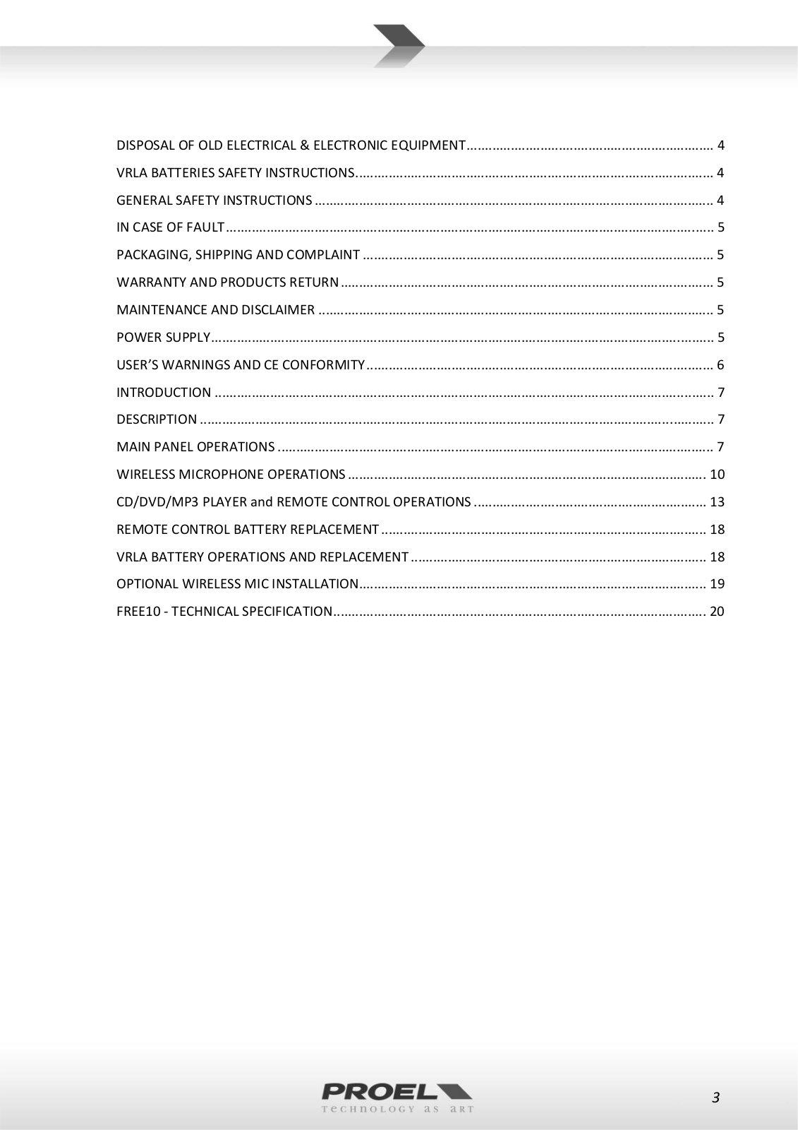
Table of contents
Loading...
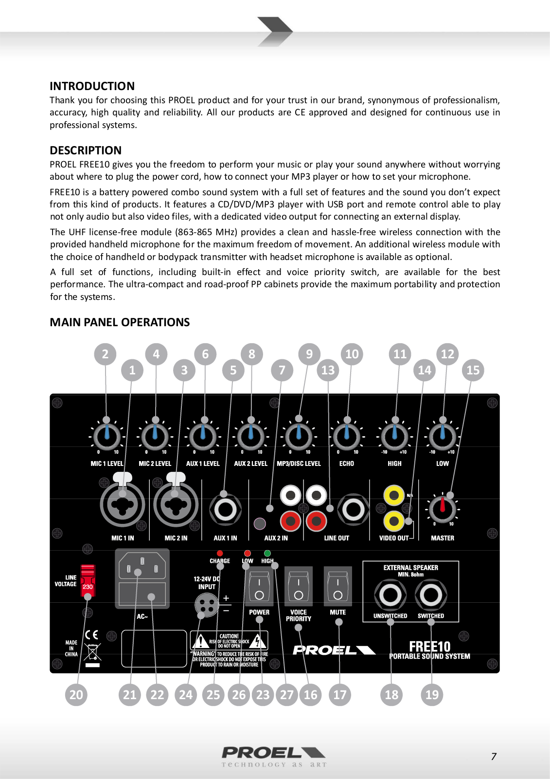
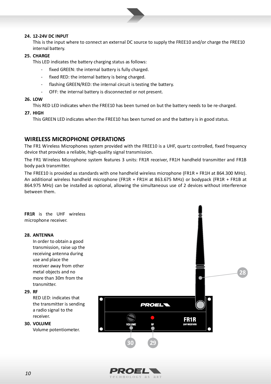
Proel FREE10 USER’S MANUAL
...
Proel USER’S MANUAL
Download
Specifications and Main Features
Frequently Asked Questions
User Manual
Download
Loading...
+
28
hidden pages
Unhide
You need points to download manuals.
1 point = 1 manual.
You can buy points or you can get point for every manual you upload.
Buy points
Upload your manuals
 Loading...