

Page 1

Service Manual
Controller
SIGMA CONTROL 2 SCREW FLUID 1.0.x.x
No.: 9_9450 00 USE
Page 2

/KKW/SSC 2.00 en 01 BA-SIGMA CONTROL-01
/KKW/SSC 2.00 01
20110128 155040
Page 3

Quick user guide
Controller
SIGMA CONTROL 2 SCREW FLUID 1.0.x.x
9_9450 00 USE
Page 4

Page 5

Contents
1. Important settings ............................................................................................................. 1
2. Setting the display language ............................................................................................ 2
3. Entering a password ........................................................................................................ 3
4. Adjusting the system set-point pressure .......................................................................... 4
5. Activating the «Timer» key ............................................................................................... 5
6. Activating the «Remote control» key ................................................................................ 8
7. Changing the control mode .............................................................................................. 11
8. Outputting important operational states of the machine ................................................... 12
9. Resetting maintenance interval counters ......................................................................... 13
10. Testing the safety relief valve ........................................................................................... 14
11. Checking the temperature sensor and overheating shutdown function ........................... 17
12. Interpreting operation messages ...................................................................................... 19
13. Interpreting diagnostic messages .................................................................................... 21
14. Interpreting fault messages .............................................................................................. 22
15. Interpreting warning messages ........................................................................................ 27
16. Interpreting system messages ......................................................................................... 31
9_9450 00 USE
Quick user guide Controller
SIGMA CONTROL 2 SCREW FLUID 1.0.x.x
i
Page 6

Contents
Quick user guide Controller
ii
SIGMA CONTROL 2 SCREW FLUID 1.0.x.x 9_9450 00 USE
Page 7

1 Important settings
1 Important settings
In this chapter, important or often used settings are explained in brief. Detailed information on func‐
tion, configuration, fault removal and important instructions concerning safe operation are found in
subsequent chapters.
Setting and other work on the machine may only be carried out by the following persons:
■ persons trained on the machine/controller and persons instructed by and under the su‐
pervision of a specialist,
■ trained technicians,
■ authorized service personnel.
9_9450 00 USE
Quick user guide Controller
SIGMA CONTROL 2 SCREW FLUID 1.0.x.x
1
Page 8

2 Setting the display language
2 Setting the display language
Precondition The display shows the operating mode.
1. Press «Enter».
The main menu is displayed.
2. Press the «UP» or «DOWN» keys until the current language is shown as active line.
8 8 p s i 0 8 : 1 5 1 7 6 ° F
········· Deutsch ·········
▶1 xxxxxxxxxx
▶2 xxxxxxxxxx
▶3 xxxxxxxxxx
▶4 xxxxxxxxxx
▶5 xxxxxxxxxx
▶6 xxxxxxxxxx
Active line with current language
Submenu
Submenu
Submenu
Submenu
Submenu
Submenu
3. Use the «Enter» key to switch to setting mode.
The currently set language flashes.
4. Move to the required language with «UP »or «DOWN».
5. Confirm the setting with «Enter».
6. Press «Escape» repeatedly to return to the main menu.
Result The display texts are now in the selected language.
Quick user guide Controller
2
SIGMA CONTROL 2 SCREW FLUID 1.0.x.x 9_9450 00 USE
Page 9
3 Entering a password
3 Entering a password
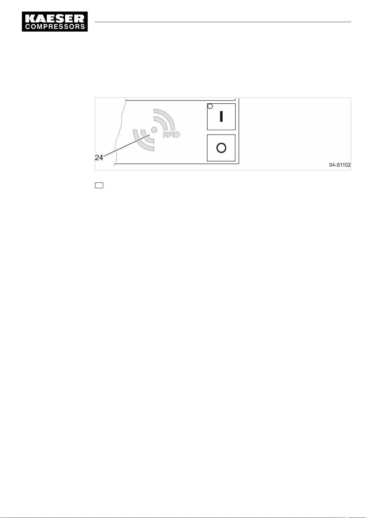
Use a supplied Equipment Card to log on at the controller.
Fig. 1 RFID reader
24 RFID reader
1. Hold the Equipment Card in front of the RFID reader for a short time (several seconds).
The system reads the data and displays your access level.
2. Press «Enter» to confirm the logon.
Result The operating mode is displayed. You are logged on.
Further information See chapter 7.2.4 for instructions on logging on to the controller manually.
9_9450 00 USE
Quick user guide Controller
SIGMA CONTROL 2 SCREW FLUID 1.0.x.x
3
Page 10

4 Adjusting the system set-point pressure
4 Adjusting the system set-point pressure
Precondition Password level 2 is activated.
The display shows the operating mode.
1. Press «Enter».
The main menu is displayed.
2. Select the
3. Press «UP» or «DOWN» repeatedly until the switching point
8 8 p s i 0 8 : 1 5 1 7 6 ° F
< Configuration ➙ Pressure control ➙ Pressure settings >
5.2.2 Pressure settings
·········
Setpoint pressure
pA SP:115 psi ¦ SD: -7.3 psi
pB SP: 110 psi ¦ SD: - 5.8 psi
·········
System pressure low ☐
menu.
pA
is displayed as active line:
Current menu
Parameter to be adjusted
Active line with current value for pA ¦ SD
Current value for pB
4. Press «Enter» to switch into setting mode.
The current value flashes.
5. Use «UP» or «DOWN» to adjust the setting for the switching point
6. Press «Enter» to accept the setting.
7. Press the «Right» key once.
8. Press «Enter» to switch into the setting mode for the switching differential.
The current value flashes.
9. Use «UP» or «DOWN» to adjust the setting for the switching differential.
10. Press «Enter» to accept the setting.
11. If necessary, adjust the value for pB in the same way.
12. Press «Escape» repeatedly to return to the main menu.
Further information See chapter 7.3 for the adjustment of the machine's pressure parameters.
pA
.
Quick user guide Controller
4
SIGMA CONTROL 2 SCREW FLUID 1.0.x.x 9_9450 00 USE
Page 11

5 Activating the «Timer» key
5 Activating the «Timer» key
Activating/deactivating the check box
Check box Check box for Reset Status
☑ ☒ activated
☐ ☐ deactivated
Tab. 1 Check box status
Precondition Password level 2 is activated.
The display shows the operating mode.
Selecting the Compressor clock menu
1. Press «Enter».
The main menu is displayed.
2. Select
Entering switching points
1. Press «Enter» to switch into setting mode.
2. Use «UP» to specify the settings for the weekdays.
3. Press «Enter» to accept the setting.
4. Press the «Right» key once.
5. Press «Enter» to switch into setting mode.
6. Use «UP» to specify the settings for the hours.
7. Press the «Right» key once.
8. Use «UP» to specify the settings for the minutes.
< Compressor clock >
The display for setting the Compressor clock timing program appears.
8 8 p s i 0 8 : 1 5 1 7 6 ° F
6 Compressor clock
Key clock : ☐
Reset: ☐
·········
01 n.a. 00:00 off
02 n.a. 00:00 off
03 n.a. 00:00 off
The
n.a.
column flashes in the active line.
Time column, hours display,
Time column, minutes display, 00
.
00 : 00
: 00
Current menu
Enter switching point 01 (active line)
Enter switching point 02
Enter switching point 03
flashes in the active line.
flashes in the active line.
9_9450 00 USE
Quick user guide Controller
SIGMA CONTROL 2 SCREW FLUID 1.0.x.x
5
Page 12

5 Activating the «Timer» key
9. Press «Enter» to accept the settings.
The display stops flashing and the time (hours/minutes) is set.
8 8 p s i 0 8 : 1 5 1 7 6 ° F
6 Compressor clock
Key clock : ☐
Reset: ☐
·········
01 Mon-Fri 06:30 on
02 Mon-Fri 12:00 off
03 Mon-Fri 13:00 on
10. Press the «Right» key once.
11. Press «Enter» to switch into setting mode.
The action
off / on
column flashes.
12. Use «UP» to specify the settings for the Compressor ON action.
13. Press «Enter» to accept the setting.
The Compressor ON action is set for the first switching point.
14. Specify further switching points in the same manner.
Current menu
Example for weekdays
Example for time
Example for the action Compressor ON
Result Weekdays, time and the Compressor ON / Compressor OFF actions are set for all switching
points.
Activating the «Timer» key
1. Use «UP» to move to line
Key clock
.
2. Press «Enter» to switch into setting mode.
The check box flashes in the active line.
8 8 p s i 0 8 : 1 5 1 7 6 ° F
6 Compressor clock
Key clock : ☑
Reset: ☐
·········
01 Mon-Fri 06:30 on
02 Mon-Fri 12:00 off
03 Mon-Fri 13:00 on
Menu
Active line with check box
Resetting all current switching points
3. Use the «UP» key to activate the check box.
4. Press «Enter» to accept the setting.
The «Timer» key is activated.
5. Press «Escape» repeatedly to return to the main menu.
6. Press the «Timer» key.
■ Proceed in the same manner to deactivate the «Timer» key.
■ All defined switching points will be reset simultaneously if you activate the
Reset
check
box.
Quick user guide Controller
6
SIGMA CONTROL 2 SCREW FLUID 1.0.x.x 9_9450 00 USE
Page 13

5 Activating the «Timer» key
Result The machine runs according to the defined switching points of the timing program.
Further information See chapter 7.4 for the Configuration of starting and stopping the machine.
See chapter 7.6.2 for the Configuration of load changeover based on a timing program.
9_9450 00 USE
Quick user guide Controller
SIGMA CONTROL 2 SCREW FLUID 1.0.x.x
7
Page 14

6 Activating the «Remote control» key
6 Activating the «Remote control» key
Further settings have to be made to allow the machine to be remotely controlled.
➤ Refer to the section "Additional information" in this chapter.
Activating/deactivating the check box
Check box Status
☑ activated
☐ deactivated
Tab. 2 Check box status
The following menus are used to activate the «Remote control» key:
■ Menu
■ Menu
< Compressor ON >
< Load control >
The function will be available as soon as the «Remote control» key in one of the menus has been
activated.
Precondition Password level 2 is activated.
The display shows the operating mode.
Activating the «Remote control» key in the Compressor ON menu
1. Press «Enter».
The main menu is displayed.
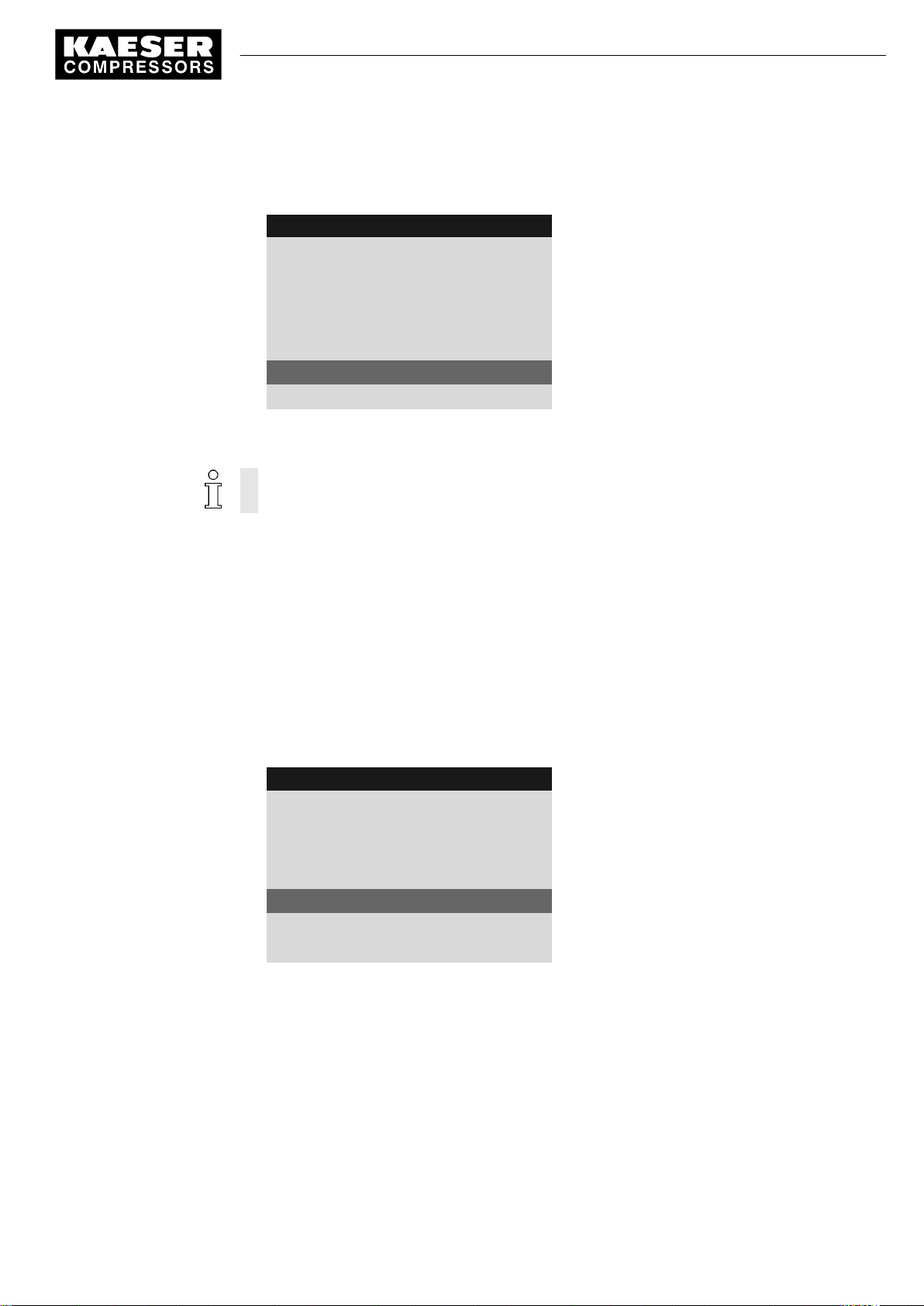
2. Select
3. Press «DOWN» repeatedly until
4. Press «Enter» to switch into setting mode.
< Configuration ➙ Compressor start ➙ Compressor ON >
The check box for Key remote will flash.
8 8 p s i 0 8 : 1 5 1 7 6 ° F
5.4.1 Compressor ON
·········
current Key
·········
RC DI 1.12 ok ☑
Key remote : ☐
Key clock : ☐
Key remote
.
is displayed as active line.
Menu
Active line with check box
5. Press «UP».
The activated check box is displayed.
Quick user guide Controller
8
SIGMA CONTROL 2 SCREW FLUID 1.0.x.x 9_9450 00 USE
Page 15
6 Activating the «Remote control» key
6. Press «Enter» to save the setting.
The «Remote control» key is activated and can be used.
8 8 p s i 0 8 : 1 5 1 7 6 ° F
5.4.1 Compressor ON
·········
current Key
·········
RC DI 1.12 ok ☑
Key remote : ☑
Key clock : ☐
7. Press «Escape» repeatedly to return to the main menu.
8. Press the «Remote control» key to enable Remote mode.
Proceed in the same manner to deactivate the «Remote control» key.
Menu
Active line with check box
Activating the «Remote control» key in the Load control menu
Precondition Password level 2 is activated.
The display shows the operating mode.
1. Press «Enter».
The main menu is displayed.
2. Select
< Configuration ➙ Pressure control ➙ Load control >
3. Press «UP» repeatedly until
4. Press «Enter» to switch into setting mode.
The check box for Key remote will flash.
8 8 p s i 0 8 : 1 5 1 7 6 ° F
5.2.3 Load control
local mode pA
·········
Remote mode : pA
Key remote : ☐
·········
current pA
5. Press «UP».
The activated check box is displayed.
Key remote
.
is displayed as active line.
Menu
Active line with check box
9_9450 00 USE
Quick user guide Controller
SIGMA CONTROL 2 SCREW FLUID 1.0.x.x
9
Page 16

6 Activating the «Remote control» key
6. Press «Enter» to accept the setting.
The «Remote control» key is activated and can be used.
8 8 p s i 0 8 : 1 5 1 7 6 ° F
5.2.3 Load control
local mode pA
·········
Remote mode : pA
Key remote : ☑
·········
current pA
7. Press «Escape» repeatedly to return to the main menu.
8. Press the «Remote control» key to enable Remote mode.
Proceed in the same manner to deactivate the «Remote control» key.
Menu
Active line with check box
Further information See chapter 7.4 for the Configuration of starting and stopping the machine.
See chapter 7.7 for the Configuration of the load changeover in sequenced mode.
10
Quick user guide Controller
SIGMA CONTROL 2 SCREW FLUID 1.0.x.x 9_9450 00 USE
Page 17

7 Changing the control mode
7 Changing the control mode
The standard setting of Control Mode depends on the machine type.
Precondition Password level 2 is activated.
The display shows the operating mode.
1. Press «Enter».
The main menu is displayed.
2. Select the
3. Press «UP» repeatedly until
The Control Mode setting is shown in the active line.
8 8 p s i 0 8 : 1 5 1 7 6 ° F
< Configuration ➙ Control Mode >
5.3 Control Mode
local mode : DUAL
·········
current DUAL
·········
▶1 Venting period
·········
local mode
menu.
is displayed as active line.
Current menu
Active line with Control Mode to be adjusted
Current control mode
4. Press «Enter» to switch into setting mode.
DUAL
flashes.
8 8 p s i 0 8 : 1 5 1 7 6 ° F
5.3 Control Mode
local mode : QUADRO
·········
current QUADRO
·········
▶1 Venting period
·········
5. Use «UP» to change the Control Mode QUADRO.
6. Press «Enter» to accept the setting.
The new Control Mode
7. Press «Escape» repeatedly to return to the main menu.
Result The Control Mode DUAL has been changed to Control Mode QUADRO.
Further information See chapter 4.6 for the functions of the control modes.
See chapter 7.5 for the Configuration of the control mode parameters.
QUADRO
is shown in the
Current menu
Active line with adjusted Control Mode
Current control mode
current
line.
9_9450 00 USE
Quick user guide Controller
SIGMA CONTROL 2 SCREW FLUID 1.0.x.x
11
Page 18

8 Outputting important operational states of the machine
8 Outputting important operational states of the ma‐
chine
Important operational machine states can be assigned via floating relay contacts as a binary signal
on the outputs DOR 1.05 – DOR 1.07. Further outputs are optionally available. You can assign ev‐
ery output only once.
Precondition Password level 2 is activated.
The display shows the operating mode.
Configuration ➙ I/O periphery ➙ DO functions menu
1. Press «Enter».
The main menu is displayed.
2. Select the
Controller ON
3. Select the required message with the «UP» or «DOWN» keys.
< Configuration ➙ I/O periphery ➙ DO functions >
is displayed in the active line.
menu.
8 8 p s i 0 8 : 1 5 1 7 6 ° F
5.7.1 DO functions
Controller ON DOR 1.05 ok ☑
Logic +
Compressor ON DOR 1.04 ☐
Logic +
Motor running DOR 1.07 ok ☑
Logic +
Assigning a message to an output
1. Press «Enter» to switch into setting mode.
The display flashes.
2. Select a free output with the «UP» or «DOWN» key.
3. Press «Enter» to accept the setting.
A message is now sent via the output assigned.
4. Press «Escape» repeatedly to return to the main menu.
Further information See chapter 7.9 for Configuration and use of the controller's inputs and outputs.
Menu
Active line with Controller ON message
12
Quick user guide Controller
SIGMA CONTROL 2 SCREW FLUID 1.0.x.x 9_9450 00 USE
Page 19

9 Resetting maintenance interval counters
9 Resetting maintenance interval counters
Example: Resetting the maintenance interval counter for Oil filter.
Precondition Maintenance has been performed.
Warning message has been acknowledged.
Access level 2 is activated.
The display shows the operating mode.
Maintenance menu
1. Press «Enter».
The main menu is displayed.
2. Select the
The maintenance counter for
3. Press «DOWN» once.
Reset
4. Press «Enter» to switch into setting mode.
The check box for
< Maintenance >
line is displayed as being active.
Reset
menu.
will flash.
Oil filter
is displayed in the active line.
8 8 p s i 0 8 : 1 5 1 7 6 ° F
4 Maintenance
Oil filter 6000 h ¦ 0005 h
Reset: ☐
·········
Oil separator 6000 h ¦ 3000 h
Reset: ☐
·········
5. Use the «DOWN» key to deactivate the check box for
8 8 p s i 0 8 : 1 5 1 7 6 ° F
4 Maintenance
Oil filter 6000 h ¦ 6000 h
Reset: ☑
·········
Oil separator 6000 h ¦ 3000 h
Reset: ☐
·········
6. Press «Enter» to accept the setting.
The check box for
Reset
is deactivated automatically.
Menu
Maintenance interval ¦ remaining time
Active line
Menu
Maintenance interval ¦ remaining new time
Active line
Reset
.
Result The remaining time of the new oil filter complies with the defined maintenance interval of 6000 h.
Further information See chapter 8.4 for setting the maintenance intervals.
See chapter 10 for the maintenance of the controller.
Quick user guide Controller
9_9450 00 USE
SIGMA CONTROL 2 SCREW FLUID 1.0.x.x
13
Page 20
10 Testing the safety relief valve
10 Testing the safety relief valve
Overview
■ Preparing the test
■ Performing the test
■ Correct conclusion of the test
■ Performing a Reset
When the check mode is activated, monitoring of internal pressure (blow-off protection - if
provided) and regulation of network pressure are deactivated.
The measured value of internal pressure pi is used to describe the following check.
Check box Status
☑ activated
☐ deactivated
Tab. 3 Check box status
Danger of injury from pressurized components!
➤ Perform the following actions in the sequence provided.
Preparing the test
1. Note the activating pressure of the safety relief valve from the machine's nameplate.
2. Press the «OFF» key to shut down the machine.
3. Close the user's shut-off valve between the machine and the air distribution network.
4. Log on to SIGMA CONTROL 2 with password level 2 (see chapter 7.2.4).
5. In operating mode, switch to the main menu with the «Enter» key.
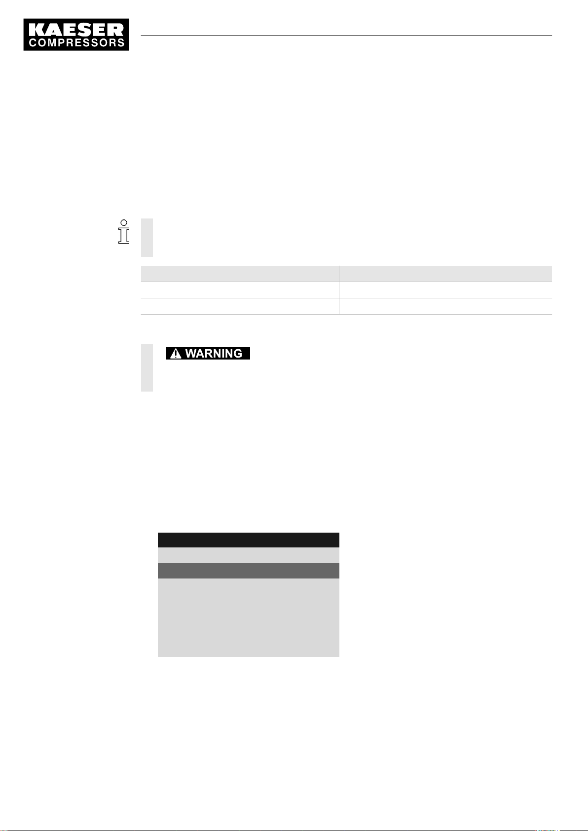
6. Select the
< Machine test ➙ TÜV inspection >
Safety valve
8 8 p s i 0 8 : 1 5 1 7 6 ° F
9.1 TÜV inspection
Safety valve: ☐
pRV : 232 psi ¦ pi 0.00 psi
Reset: ☐
·········
ADT ⇞ : ☐
Offset : 32 °F ¦ ADT ⇞ 32 °F
menu.
line is displayed as being active.
Menu
Active line with check box
Safety relief valve activating pressure (example)
14
Performing the test
1. Press «Enter» to switch into setting mode.
The check box in the active line flashes.
2. Use the «UP» key to activate the check box.
Quick user guide Controller
SIGMA CONTROL 2 SCREW FLUID 1.0.x.x 9_9450 00 USE
Page 21
10 Testing the safety relief valve
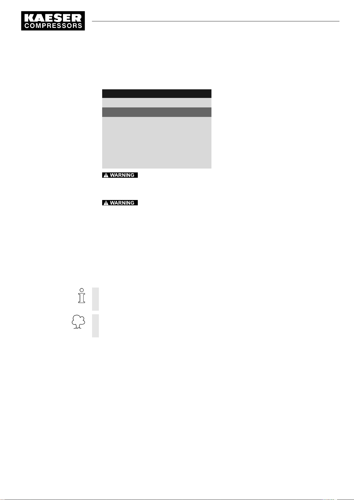
3. Press «Enter» to accept the setting.
The test mode is now activated.
The monitoring of internal and network set point pressures is deactivated!
8 8 p s i 0 8 : 1 5 1 7 6 ° F
9.1 TÜV inspection
Safety valve: ☑
pRV : 232 psi ¦ pi 36 psi
Reset: ☐
·········
Menu
Active line with check box
Activating pressure safety relief valve ( pRV ) ¦ Inter‐
nal pressure pi ( current )
4.
Excessive noise is caused when the safety relief valve blows off!
➤ Close all access doors, replace and secure all removable panels.
➤ Wear hearing protection.
5.
Risk of burns due to released cooling oil and compressed air when blowing off
the safety relief valve!
➤ Close all access doors, replace and secure all removable panels.
➤ Wear eye protection.
6. Press and hold the «ON» key.
The machine switches to load, the machine's internal pressure pi rises.
7. Manually monitor on the display the pressure rise pi during the TÜV inspection.
8. If the internal pressure pi increases to more than 10 % above the correct opening pressure of
the safety relief valve, shut down the machine with the «OFF» key.
9. Have the Safety valve replaced immediately.
If the alarm message
internal pressure was exceeded by 29 psi.
➤ Have the safety relief valve replaced immediately.
Avoid oil mist:
➤ Release the «ON» key immediately when the safety relief valve responds, in order to pre‐
vent unnecessary oil mist.
pRV ⇞
appears, the safety relief valve is defective. The permissible
9_9450 00 USE
Correct conclusion of the test
1. Press «Enter» to switch into setting mode.
The check box in the active line flashes.
2. Use the «DOWN» key to deactivate the check box.
3. Press «Enter» to accept the setting.
The "Safety relief valve" test mode is de-activated and the test is completed.
4. Press «Escape» repeatedly to return to the main menu.
5. Open the shut-off valve from the machine.
Result The machine is ready for operation.
Quick user guide Controller
SIGMA CONTROL 2 SCREW FLUID 1.0.x.x
15
Page 22

10 Testing the safety relief valve
Resetting
If the test is canceled when opening the safety relief valve, the internal pressure
highest measured value.
Activate the check box for Reset in order to reset the stored value.
➤ Activate the check box for Reset.
Further information See chapter 8.5 to test the safety relief valve.
pi
will indicate the
16
Quick user guide Controller
SIGMA CONTROL 2 SCREW FLUID 1.0.x.x 9_9450 00 USE
Page 23

11 Checking the temperature sensor and overheating shutdown
function
11 Checking the temperature sensor and overheating
shutdown function
The machine should shut down if the airend discharge temperature (ADT) reaches a maximum of
230 °F.
SIGMA CONTROL 2 will simulate a higher temperature for checking this function.
For this purpose, SIGMA CONTROL 2 automatically determines an offset value to be displayed.
During the test mode, this Offset is added to the actual airend discharge temperature to cause the
machine to shut down prematurely.
In standard operation, SIGMA CONTROL 2 generates the "overtemperature" fault message when
the maximum airend discharge temperature is reached. Since the modified test temperature is 4 °F
below the fault message switching point for overtemperature, the system will not generate a fault
message in test mode.
Overview
■ Shut down the machine and allow to cool down slightly
■ Performing the test
■ Correct conclusion of the test
■ Performing a Reset
Performing the test
Precondition Machine cooled down by approx. 9 °F
1. Log on to SIGMA CONTROL 2 with access level 2. (see section 7.2.4).
2. In operating mode, switch to the main menu with the «Enter» key.
3. Select the
Safety valve
4. Press «DOWN» repeatedly until
5. Press «Enter» to switch into setting mode.
The check box in the active line flashes.
8 8 p s i 0 8 : 1 5 1 6 4 ° F
6. Use the «UP» key to activate the check box.
< Machine test ➙ TÜV inspection >
is displayed in the active line.
9.1 TÜV inspection
·········
ADT ⇞ : ☐
Offset : 32 °F ¦ ADT ⇞ 32 °F
Reset: ☐
ADT ⇞
menu.
is displayed as active line.
Menu
Active line
9_9450 00 USE
Quick user guide Controller
SIGMA CONTROL 2 SCREW FLUID 1.0.x.x
17
Page 24

11 Checking the temperature sensor and overheating shutdown
function
7. Press «Enter» to accept the setting.
The Offset display changes to
The ADT ⇞ display changes to
The test mode is now activated.
8 8 p s i 0 8 : 1 5 1 6 4 ° F
9.1 TÜV inspection
·········
ADT ⇞ : ☑
Offset : 95 °F ¦ ADT ⇞ 226 °F
Reset: : ☐
8. Press the «ON» key to switch the machine to LOAD.
The machine switches to LOAD and the airend discharge temperature rises again.
The machine will switch off as soon as
95 °F
226 °F
.
.
Menu
Active line
Offset ¦ ADT ⇞ in test mode
ADT
attains a value of
226 °F
.
The machine does not shut down?
➤ Abort the test and contact KAESER Service as soon as possible.
Correct conclusion of the test
1. Press «Enter» to switch into setting mode.
The check box in the active line flashes.
2. Use the «DOWN» key to deactivate the check box.
3. Press «Enter» to accept the setting.
The offset is reset to
The test mode is de-activated and the test is completed.
4. Press «Escape» repeatedly to return to the main menu.
Resetting
ADT ⇞
aborted.
Activate the check box for Reset in order to reset the stored value.
➤ Activate the check box for Reset.
Further information See chapter 8.6 for testing the temperature sensor.
will display the highest measured value if the test for switching off at overtemperature is
32 °F
.
18
Quick user guide Controller
SIGMA CONTROL 2 SCREW FLUID 1.0.x.x 9_9450 00 USE
Page 25

12 Interpreting operation messages
12 Interpreting operation messages
The controller will automatically display operation messages informing you about the current opera‐
tional state of the machine.
Operating messages are identified with the letter O.
The message numbers are not numbered consecutively.
Messages 0081 to 0095 are customer-specific and undefined. Complete them with your defined
message text and interpretation.
Message Meaning
0001 O
load control pA
0002 O
load control pB
0003 O
load control RC
0004 O
load control RB
0005 O
ready
0006 O
IDLE
0007 O
ON LOAD
0008 O
off
0009 O
Compressor ON
0010 O
Controller ON
0011 O
Cold start release
0025 O
Setpoint pressure pA
0026 O
Setpoint pressure pB
0027 O
Power OFF → ON
0028 O
DYNAMIC motor T↑
0081 O
The machine is regulated by system set point pressure pA.
The machine is regulated by system set point pressure pB.
The machine is regulated via the remote contactor.
The machine is remotely regulated via the bus connection.
The machine is switched on and in STANDSTILL operating mode.
The machine is switched on and in IDLE operating mode.
The machine is switched on and in LOAD operating mode.
The machine is switched off.
The power supply is connected.
The machine is switched on.
The power supply is connected.
The controller is powered.
The machine can be switched on although the machine temperature is be‐
low the permissible starting temperature.
The machine can be switched on only as long as the message is displayed.
The value for pA is output.
The value for pB is output.
Request:
Switch the power supply off and on.
Control mode DYNAMIC:
The temperature of the compressor motor is too high.
9_9450 00 USE
Quick user guide Controller
SIGMA CONTROL 2 SCREW FLUID 1.0.x.x
19
Page 26

12 Interpreting operation messages
Message Meaning
0082 O
0083 O
0084 O
0085 O
0086 O
0087 O
0088 O
0089 O
0090 O
0091 O
0092 O
0093 O
p-Switch pi
0094 O
T-Switch ADT
0095 O
p-Switch pN
20
Tab. 4 Operational Messages
Quick user guide Controller
SIGMA CONTROL 2 SCREW FLUID 1.0.x.x 9_9450 00 USE
Page 27

13 Interpreting diagnostic messages
13 Interpreting diagnostic messages
Diagnostic messages are identified with the letter D.
They provide information on the status of the controller, the connected input and output modules
and support the KAESER service in troubleshooting.
9_9450 00 USE
Quick user guide Controller
SIGMA CONTROL 2 SCREW FLUID 1.0.x.x
21
Page 28

14 Interpreting fault messages
14 Interpreting fault messages
Fault messages are identified with the letter A.
The message numbers are not numbered consecutively.
Messages 0081 to 0095 are customer-specific and may differ from the suggested values. Com‐
plete them with your defined message text, possible causes and remedies.
Message Possible cause Remedy
0001 A
Direction of rotation
0002 A
Motor T⇞
0003 A
pRV ⇞
0004 A
EMERGENCY STOP
0005 A
Oil separator T⇞
0007 A
Mains monitor
0009 A
Sigma Control T⇞
0010 A
Blow-off protection ⇞
0011 A
Fan M4 I⇞
0012 A
Access doors
0013 A
Motor I⇞
0014 A
Fan M5 I⇞
The compressor drive motor is
turning in the wrong direction.
Compressor drive motor over‐
heated.
The activating pressure of the
safety relief valve on the oil sepa‐
rator tank has been exceeded.
EMERGENCY STOP control de‐
vice actuated.
Maximum air temperature at the
oil separator tank outlet is ex‐
ceeded.
Fault in main power supply. Have the main power sup‐
Permissible enclosure tempera‐
ture for SIGMA CONTROL 2 ex‐
ceeded.
The activating pressure of the
safety relief valve on the oil sepa‐
rator tank has been exceeded.
Overload shut-down of the first
fan motor.
Door open / interlocked panel re‐
moved while the machine is run‐
ning.
Overload shut-down of the com‐
pressor drive motor.
Overload shut-down of the sec‐
ond fan motor.
Change over phase lines L1
and L2.
Clean the motor.
Keep ambient conditions
within specified limits.
Change the safety relief
valve.
Unlatch the push-button.
Check the line to the trip re‐
lay.
ply checked.
Keep ambient conditions
within specified limits.
Control cabinet:
Check filter mats and fan.
Change the oil separator
cartridge.
Open the shut-off valve in
the venting line.
Investigate cause of shut-
down.
Reset the overload relay.
Fit and secure all panels
and close access doors.
Investigate cause of shutdown.
Change the oil separator
cartridge.
Investigate cause of shutdown.
Reset the overload relay.
22
Quick user guide Controller
SIGMA CONTROL 2 SCREW FLUID 1.0.x.x 9_9450 00 USE
Page 29

14 Interpreting fault messages
Message Possible cause Remedy
0015 A
ADT ⇞
0016 A
Fan M6 I⇞
0019 A
Internal pressure pi⇟
0021 A
Refrigeration dryer T⇟
0022 A
Oil separator dp⇞
0023 A
Motor bearings
0024 A
Water-cooling water shortage
0034 A
Mains contactor on?
0035 A
Fan M7 I⇞
0038 A
PD T⇟
0039 A
PD T⇞
0040 A
Mains contactor off?
0041 A
Mains voltage ⇟
0042 A
Back pressure stop
0043 A
ADT dT/dt ⇞
0044 A
No pressure buildup
Maximum permissible airend dis‐
charge temperature (ADT) ex‐
ceeded.
Overload shut-down of the third
fan motor.
– –
Refrigeration dryer:
Compressed air temperature too
low.
Oil separator cartridge clogged. Change the oil separator
Drive motor bearings overheated. Re-grease the motor bear‐
Cooling water pressure is too low. Check cooling water supply.
Main contactor does not close. Check main contactor and
Overload shut-down of the control
cabinet fan motor.
Package discharge (PD) tempera‐
ture too low.
Package discharge (PD) tempera‐
ture too high.
Main contactor does not open. Check main contactor and
Second power failure. Check power supply volt‐
Back pressure in the oil separator
tank caused by defective venting.
The rate of rise of the airend dis‐
charge temperature (ADT) is too
fast.
The machine does not produce
compressed air.
The working pressure does not
rise above 50 psi within the preset
period.
Keep ambient conditions
within specified limits.
Clean the cooler.
Check the cooling oil level.
Investigate cause of shutdown.
Reset the overload relay.
Contact an authorized
KAESER service represen‐
tative.
cartridge.
ings.
wiring.
Contact an authorized
KAESER service represen‐
tative.
Contact an authorized
KAESER service represen‐
tative.
Check the cooling oil level.
Clean the radiator.
Check the fan motor.
wiring.
age.
Check the door interlock
switch.
Check venting line.
Check the cooling oil level.
Check the machine for
leaks.
Check coupling / V-belt.
9_9450 00 USE
Quick user guide Controller
SIGMA CONTROL 2 SCREW FLUID 1.0.x.x
23
Page 30

14 Interpreting fault messages
Message Possible cause Remedy
0045 A
Compressor T⇟
0048 A
High-voltage cell
0051 A
Aggregate A
0052 A
Aggregate B
0056 A
RD condensate drain
0057 A
Model
0058 A
Condensate drain
0059 A
Back pressure run
0060 A
Softstart
0061 A
Oil separator dT/dt⇞
0062 A
Refrigeration dryer p⇞
0063 A
Refrigeration dryer p⇟
0081 A
0082 A
0083 A
Thermostatic valve defective Contact an authorized
KAESER service represen‐
tative.
Fault in the high voltage cell. Contact an authorized
KAESER service represen‐
tative.
Aggregate A failed. Contact an authorized
KAESER service represen‐
tative.
Aggregate B failed. Contact an authorized
KAESER service represen‐
tative.
Refrigeration dryer:
The condensate drain is defec‐
tive.
Compressor model uncertain. Contact an authorized
The condensate drain is defec‐
tive.
Drive belt or coupling broken. Drive belt:
Fault in the soft start equipment. Contact an authorized
The rate of rise of the airend dis‐
charge temperature is too fast.
Refrigeration dryer:
Pressure too high in the refriger‐
ant circuit.
Safety pressure switch tripped.
Refrigeration dryer:
Refrigerant lost; pressure in the
refrigerant circuit too low. Inlet
pressure switched tripped.
Refrigeration dryer:
Check condensate drain
and condensate conduits.
KAESER service represen‐
tative.
Check condensate drain
and condensate conduits.
Replace drive belt.
Coupling:
Contact an authorized
KAESER service represen‐
tative.
KAESER service represen‐
tative.
Check the cooling oil level.
Clean the refrigerant con‐
denser.
Check the fan motor.
Maintain operating condi‐
tions.
Contact an authorized
KAESER service represen‐
tative.
24
Quick user guide Controller
SIGMA CONTROL 2 SCREW FLUID 1.0.x.x 9_9450 00 USE
Page 31

14 Interpreting fault messages
Message Possible cause Remedy
0084 A
0085 A
0086 A
0087 A
0088 A
0089 A
0090 A
0091 A
0092 A
0093 A
p-Switch pi
0094 A
T-Switch ADT
0095 A
p-Switch pN
0097 A
High-voltage cell on?
0098 A
High-voltage cell off?
0099 A
Mains contactor on?
0100 A
Mains contactor off?
0101 A
Motor I⇞
0102 A
Fan M4 I⇞
0200 A
Compressor motor USS alarm
0201 A
Compressor motor USS alarm
High-voltage cell does not acti‐
vate.
High-voltage cell does not deacti‐
vate.
Main contactor does not close. Check main contactor and
Main contactor does not open. Check main contactor and
Overload shut-down of the com‐
pressor drive motor.
Overload shut-down of the first
fan motor.
Frequency converter fault Contact an authorized
Frequency converter fault Contact an authorized
Check high-voltage cell and
wiring.
Check high-voltage cell and
wiring.
wiring.
wiring.
Investigate cause of shut-
down.
Change the oil separator
cartridge.
Investigate cause of shut-
down.
Reset the overload relay.
KAESER service represen‐
tative.
KAESER service represen‐
tative.
9_9450 00 USE
Quick user guide Controller
SIGMA CONTROL 2 SCREW FLUID 1.0.x.x
25
Page 32

14 Interpreting fault messages
Message Possible cause Remedy
0202 A
Compressor motor USS alarm
0205 A
Compressor motor USS alarm
0210 A
Compressor motor FC Motor
overload alarm
0211 A
Compressor motor FC Group
alarm
Tab. 5 Fault messages and measures
Frequency converter fault Contact an authorized
KAESER service represen‐
tative.
Communications error Check connection and line
path.
Frequency converter fault Contact an authorized
KAESER service represen‐
tative.
Frequency converter fault Contact an authorized
KAESER service represen‐
tative.
26
Quick user guide Controller
SIGMA CONTROL 2 SCREW FLUID 1.0.x.x 9_9450 00 USE
Page 33

15 Interpreting warning messages
15 Interpreting warning messages
Warning messages are identified with the letter W.
The message numbers are not numbered consecutively.
Messages 0081 to 0092 are customer-specific and may differ from the suggested values. Com‐
plete them with your defined message text, possible causes and remedies.
Message Possible cause Remedy
0002 W
Motor T↑
0003 W
V-belt tension
0004 W
Oil separator dp↑
0005 W
Start inhibit
0007 W
Motor bearings
0008 W
ADT↑
0010 W
Buffer battery
0011 W
Oil filter Δp↑
0012 W
Modem problem
0013 W
Air filter dp↑
0015 W
Bus alarm
0016 W
Error: RAM
0017 W
Refrigeration dryer T↓
Drive motor overheating. Clean the motor.
Belt tension is too low. Re-tension drive belt.
The pressure drop across the oil
separator cartridge has risen.
Oil separator cartridge clogged.
Too frequent manual on and off
switching.
Drive motor bearing defective. Contact an authorized KAESER ser‐
Maximum airend discharge tem‐
perature will soon be reached.
Data retention battery is almost
discharged.
The pressure differential of the oil
filter has risen.
Oil filter clogged.
SIGMA CONTROL 2 does not rec‐
ognize modem.
Air filter clogged. Change the air filter element.
The bus link from the Profibus DP
interface is interrupted.
Internal RAM defective. Contact an authorized KAESER ser‐
Refrigeration dryer:
Compressed air temperature too
high.
Keep ambient conditions within
specified limits.
Change the oil separator cartridge.
Do not exceed the maximum num‐
ber of motor switchings per hour
when manual on/off switching.
vice representative.
Clean the radiator.
Check the cooling oil level.
Replace the oil filter.
Ensure adequate ventilation.
Keep surrounding temperature with‐
in recommended limits.
Change the battery.
Change the oil filter.
Check the link between the
SIGMA CONTROL 2 and the mo‐
dem.
Check bus highway and plug.
vice representative.
Maintain operating conditions.
Clean the refrigerant condenser.
Clean the cooler.
Install an extractor fan.
9_9450 00 USE
Quick user guide Controller
SIGMA CONTROL 2 SCREW FLUID 1.0.x.x
27
Page 34

15 Interpreting warning messages
Message Possible cause Remedy
0018 W
Refrigeration dryer p↓
0025 W
Oil separator h⇞
0026 W
Oil change h⇞
0027 W
Oil filter h⇞
0028 W
Air filter h⇞
0029 W
Valve inspection h⇞
0030 W
Belt/coupling inspection
h⇞
0031 W
Motor bearing h⇞
0032 W
Electrical equipment h⇞
0033 W
Fan bearing h⇞
0034 W
PD T↓
0035 W
PD T↑
0036 W
Motor starts /h⇞
0037 W
Motor starts /d⇞
0038 W
Blow-off protection ↑
0041 W
Mains voltage ↓
Refrigeration dryer:
Refrigerant lost; pressure in the re‐
frigerant circuit too low. Inlet pres‐
sure switched tripped.
Oil separator cartridge:
Maintenance interval has elapsed.
Cooling oil:
Maintenance interval has elapsed.
Oil filter:
Maintenance interval has elapsed.
Air filter:
Maintenance interval has elapsed.
Valves:
Maintenance interval has elapsed.
Belt tension/coupling:
Maintenance interval has elapsed.
Motor bearing of compressor mo‐
tor:
Maintenance interval has elapsed.
Electric components and installa‐
tion:
Maintenance interval has elapsed.
Motor bearing of fan motors:
Maintenance interval has elapsed.
Package discharge (PD) tempera‐
ture too low.
Compressed air discharge temper‐
ature too high.
The permissible number of motor
starts was exceeded in the last
60 minutes.
The permissible number of motor
starts was exceeded in the last
24 hours.
The safety relief valve's activating
pressure will soon be reached.
1. Power failure:
The machine is automatically restarted.
Contact an authorized KAESER ser‐
vice representative.
Change the oil separator cartridge.
Change the cooling oil.
Change the oil filter.
Change the air filter element.
Contact an authorized KAESER ser‐
vice representative.
Carry out a visual inspection.
Re-tension drive belt.
Contact an authorized KAESER ser‐
vice representative.
Inspect and reset the maintenance
interval counter.
Contact an authorized KAESER ser‐
vice representative.
Contact an authorized KAESER ser‐
vice representative.
Clean the radiator.
Check the cooling oil level.
Extend the idle period.
Increase the capacity of air receiver.
Increase the cross-section of piping
between compressor and air receiv‐
er.
Extend the idle period.
Increase the capacity of air receiver.
Increase the cross-section of piping
between compressor and air receiv‐
er.
Change the oil separator cartridge.
Open the shut-off valve in the vent‐
ing line.
Check power supply.
Check the door interlock switch.
28
Quick user guide Controller
SIGMA CONTROL 2 SCREW FLUID 1.0.x.x 9_9450 00 USE
Page 35
15 Interpreting warning messages
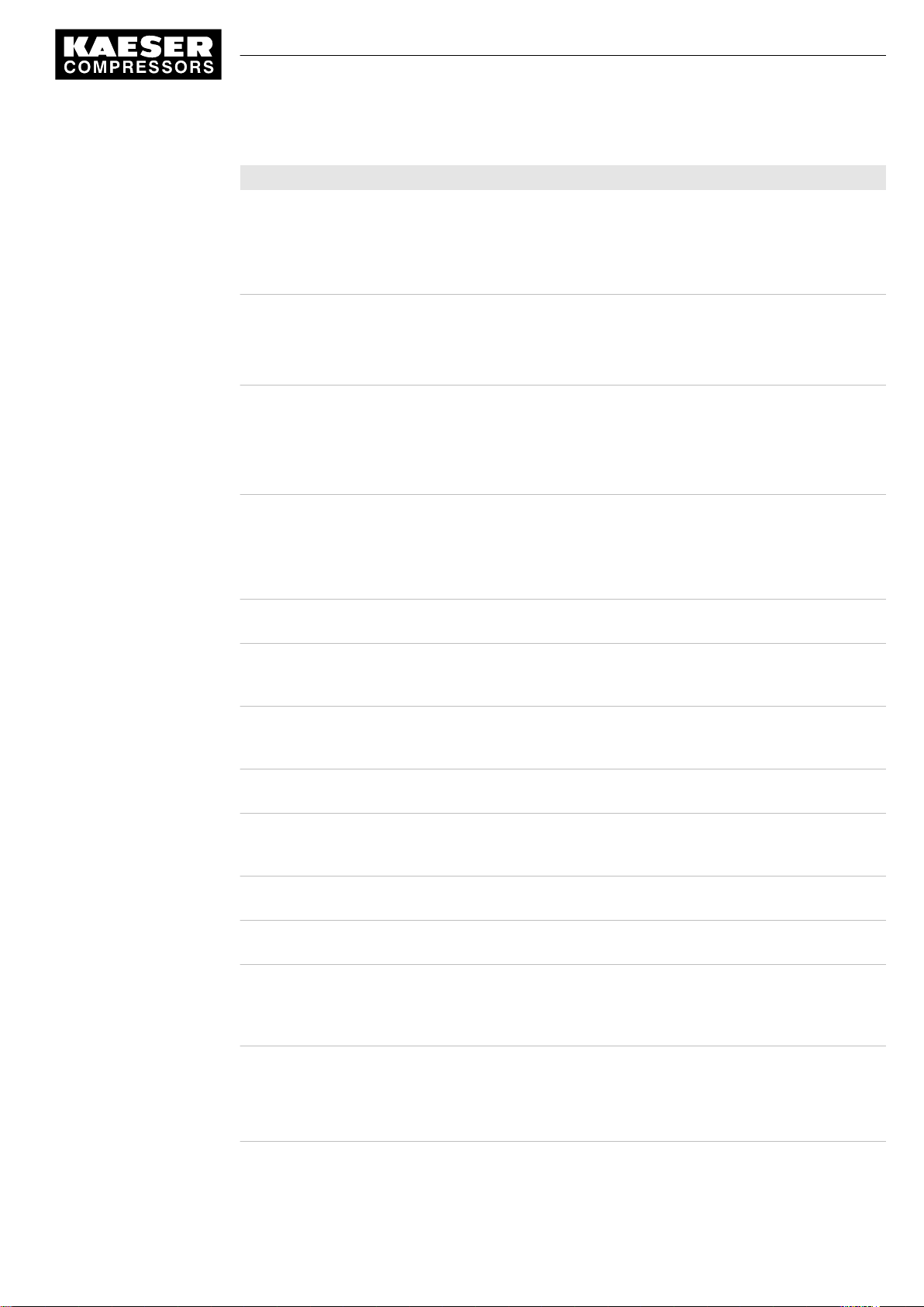
Message Possible cause Remedy
0043 W
External load signal?
0044 W
Oil T↓
0046 W
System pressure ↓
0047 W
No pressure buildup
0048 W
Bearing lube h⇞
0049 W
Annual maintenance
0059 W
Start T↓↓
0060 W
Start T↓
0061 W
Compressor T↓
0066 W
Air filter dp⇡
0068 W
Condensate drain
0069 W
Refrigeration dryer p↑
0070 W
Refrigeration dryer T↑
Ambiguous external load signal:
Increased cut-out pressure ex‐
ceeded.
The external load control has not
switched to idle (off load).
Cooling oil temperature too low. Check temperature switch, line and
Network pressure has fallen below
the set 'low' value.
Air consumption too high.
The compressor cannot build-up to
working pressure.
Re-grease the motor bearings.
Maintenance interval has elapsed.
Last maintenance was 1 year ago. Carry out the necessary mainte‐
The airend temperature is too low
(<14 °F) for the machine to be op‐
erated.
The airend temperature is too low
(<35 °F).
The airend discharge temperature
(ADT) did not reach the minimum
value within the specified time.
Initial warning:
Air filter clogged.
The condensate drain is defective. Check the condensate drain and
Refrigeration dryer:
Pressure too high in the refrigerant
circuit.
Safety pressure switch tripped.
Refrigeration dryer:
Compressed air temperature too
high.
Check settings of the external con‐
troller. Take into account pressure
drops across filters and dryer.
connection.
Check the oil circulation.
Increase room temperature.
Check air demand.
Check cable runs and sensor con‐
nections.
Check the 'sys.press. low' warning
setting.
Check for air leaks.
Check the value for internal pres‐
sure given in the
>
menu against the reading on the
oil separator tank pressure gauge.
Re-grease the motor bearings.
nance and reset the corresponding
maintenance interval counter.
Keep ambient conditions within
specified limits.
Keep ambient conditions within
specified limits.
Contact an authorized KAESER ser‐
vice representative.
Change the air filter element soon.
drain line.
Clean the refrigerant condenser.
Check the fan motor.
Maintain operating conditions.
Maintain operating conditions.
Clean the refrigerant condenser.
Clean the cooler.
Install an extractor fan.
<analog data
9_9450 00 USE
Quick user guide Controller
SIGMA CONTROL 2 SCREW FLUID 1.0.x.x
29
Page 36

15 Interpreting warning messages
Message Possible cause Remedy
0071 W
Oil level ↓
0072 W
RD condensate drain
0081 W
0082 W
0083 W
0084 W
0085 W
0086 W
0087 W
0088 W
0089 W
0090 W
0091 W
0092 W
0093 W
p-Switch pi
0094 W
T-Switch ADT
0095 W
p-Switch pN
Cooling oil level too low. Replenish the cooling oil.
Refrigeration dryer:
The condensate drain is defective.
Check condensate drainage
30
Tab. 6 Warning messages and remedies
Quick user guide Controller
SIGMA CONTROL 2 SCREW FLUID 1.0.x.x 9_9450 00 USE
Page 37

16 Interpreting system messages
16 Interpreting system messages
System messages are identified with the letter Y.
The message numbers are not numbered consecutively.
Message Possible cause Remedy
0001 Y
Hardware watchdog reset
0002 Y
Internal software error
0003 Y
Filesystem Read/Write failure
0004 Y
CPU load too high
0005 Y
RAM out of memory
1000 Y
RFID error: switch SIGMA
CONTROL power supply OFF→ON!
System error Contact an authorized KAESER service
representative.
System error Contact an authorized KAESER service
representative.
System error Contact an authorized KAESER service
representative.
System error Contact an authorized KAESER service
representative.
System error Contact an authorized KAESER service
representative.
System error Contact an authorized KAESER service
representative.
Tab. 7 System messages and remedies
9_9450 00 USE
Quick user guide Controller
SIGMA CONTROL 2 SCREW FLUID 1.0.x.x
31
Page 38

16 Interpreting system messages
32
Quick user guide Controller
SIGMA CONTROL 2 SCREW FLUID 1.0.x.x 9_9450 00 USE
Page 39

Contents
1 Regarding this Document
1.1 Using this document ......................................................................................................... 1
1.2 Copyright .......................................................................................................................... 1
1.2.1 Software .............................................................................................................. 1
1.3 Updating the SIGMA CONTROL 2 operating manual ...................................................... 1
1.4 Symbols and labels .......................................................................................................... 2
1.4.1 Warnings ............................................................................................................. 2
1.4.2 Potential damage warnings ................................................................................ 2
1.4.3 Other alerts and their symbols ............................................................................ 3
2 Technical Data
2.1 SIGMA CONTROL 2 Controller ....................................................................................... 4
2.1.1 User interface with display, CPU and interfaces ................................................. 4
2.1.2 Input/output modules .......................................................................................... 5
2.1.3 Sensors ............................................................................................................... 7
3 Safety and Responsibility
3.1 Basic instructions ............................................................................................................. 9
3.2 Specified use .................................................................................................................... 9
3.3 Improper use .................................................................................................................... 9
4 Design and Function
4.1 The controller ................................................................................................................... 10
4.2 Operating panel SIGMA CONTROL 2 ............................................................................ 11
4.3 Display ............................................................................................................................. 13
4.3.1 Operating mode .................................................................................................. 14
4.3.2 Main menu .......................................................................................................... 14
4.3.3 Setting parameters ............................................................................................. 15
4.3.4 Activating keys with check boxes ....................................................................... 16
4.4 Access rights .................................................................................................................... 16
4.4.1 Secure storage of the RFID Equipment Cards ................................................... 16
4.5 Menus – overview ............................................................................................................ 16
4.5.1 Operating mode .................................................................................................. 16
4.5.2 Menu structure .................................................................................................... 17
4.6 Operating modes and control modes ............................................................................... 24
4.6.1 Operating modes ................................................................................................ 24
4.6.2 Control modes .................................................................................................... 25
4.6.3 Frequency-controlled drive (SFC) ....................................................................... 26
4.7 MODULATING control ..................................................................................................... 27
5 Installation and Operating Conditions
5.1 Maintaining ambient conditions ........................................................................................ 28
5.2 Installation conditions ....................................................................................................... 28
6 Installation
6.1 Reporting Transport Damage ........................................................................................... 29
6.2 Machine identification ....................................................................................................... 29
No.: 9_9450 00 USE
7 Initial Start-up
7.1 Outline .............................................................................................................................. 30
7.2 Configuring the controller ................................................................................................. 30
7.2.1 Selecting menu options ...................................................................................... 30
7.2.2 Changing the display language .......................................................................... 31
7.2.3 Access rights with equipment card ..................................................................... 31
7.2.4 Access right via manual input ............................................................................. 32
7.2.5 Creating additional user names .......................................................................... 33
7.2.6 Checking/setting time and date .......................................................................... 34
Service Manual Controller
SIGMA CONTROL 2 SCREW FLUID 1.0.x.x
i
Page 40

Contents
7.2.7 Setting display formats ....................................................................................... 35
7.2.8 Setting and activating summer/winter time ......................................................... 38
7.3 Pressure parameters of the machine ............................................................................... 38
7.3.1 Displaying pressure parameters ......................................................................... 39
7.3.2 Configuring the pressure parameters for compressors ...................................... 40
7.3.3 Activating/deactivating the «IDLE» key .............................................................. 43
7.4 Configuring machine start and stop ................................................................................. 44
7.4.1 Automatic start/stop in programmed clock mode ................................................ 44
7.4.2 Setting up the holiday period .............................................................................. 47
7.4.3 Starting the machine remotely from a control center (remote ON/OFF or
remote control function) ......................................................................................
7.4.4 Activating/deactivating the idle phase (Venting period function) ........................ 50
7.4.5 Activating/deactivating and adjusting the "automatic restart after a power
failure" function ...................................................................................................
7.5 Activating and setting up the control modes .................................................................... 53
7.5.1 Selecting a control mode .................................................................................... 53
7.5.2 Adjusting Idle period of Control Mode DUAL ..................................................... 54
7.5.3 Adjusting the unloaded and minimum running period in Control Mode
QUADRO ...........................................................................................................
7.6 Configuring the machine for local mode ........................................................................... 55
7.6.1 Selecting <Configuration ➙ Pressure control ➙ Load control > ......................... 56
7.6.2 Configuring the system pressure set-point changeover using the timer
program ..............................................................................................................
7.6.3 Configuring the system pressure set-point changeover using the Timer .......... 59
7.7 Configuring the machine for master control ..................................................................... 61
7.8 Configuring e-mail ............................................................................................................ 61
7.9 Configuring input and output signals ................................................................................ 61
7.10 Configuring the compressed air outlet temperature (PD temperature) ............................ 61
7.11 Activating remote acknowledgement ............................................................................... 61
7.12 Linking to an external pressure transducer ...................................................................... 62
7.13 Activating the energy-saving mode for Dryer .................................................................. 62
7.14 Commissioning the machine ............................................................................................ 62
47
51
55
56
8 Operation
8.1 Switching on and off ......................................................................................................... 63
8.1.1 Switching on ....................................................................................................... 63
8.1.2 Switching off ....................................................................................................... 63
8.1.3 Switching off in an emergency and switching on again ...................................... 64
8.2 Acknowledging alarm and warning messages ................................................................. 64
8.3 Displaying operating data ................................................................................................. 65
8.3.1 Interpreting operation messages ........................................................................ 66
8.4 Setting the maintenance interval ...................................................................................... 68
8.5 Testing the safety relief valve ........................................................................................... 68
8.6 Checking the temperature sensor and overheating shutdown function ........................... 70
9 Fault Recognition and Rectification
9.1 Basic instructions ............................................................................................................. 73
9.2 Interpreting fault messages .............................................................................................. 73
9.3 Interpreting system messages ......................................................................................... 77
9.4 Interpreting diagnostic messages .................................................................................... 78
9.5 Interpreting warning messages ........................................................................................ 78
10 Maintenance
10.1 Safety ............................................................................................................................... 83
Service Manual Controller
ii
SIGMA CONTROL 2 SCREW FLUID 1.0.x.x No.: 9_9450 00 USE
Page 41

Contents
11 Spares, Operating Materials, Service
11.1 Note the nameplate .......................................................................................................... 84
11.2 KAESER AIR SERVICE .................................................................................................. 84
11.3 Service Addresses ........................................................................................................... 84
11.4 Displaying the version number, machine model, material, serial, and equipment
numbers ...........................................................................................................................
12 Decommissioning, Storage and Transport
12.1 De-commissioning ............................................................................................................ 85
12.2 Packing ............................................................................................................................ 85
12.3 Storage ............................................................................................................................. 85
12.4 Transporting ..................................................................................................................... 85
12.5 Disposal ........................................................................................................................... 85
84
No.: 9_9450 00 USE
Service Manual Controller
SIGMA CONTROL 2 SCREW FLUID 1.0.x.x
iii
Page 42

Contents
Service Manual Controller
iv
SIGMA CONTROL 2 SCREW FLUID 1.0.x.x No.: 9_9450 00 USE
Page 43

List of Illustrations
Fig. RFID reader ................................................................................................................................ 3
Fig. 1 System structure ........................................................................................................................ 10
Fig. 2 Keys – overview ......................................................................................................................... 11
Fig. 3 Indicators .................................................................................................................................... 12
Fig. 4 RFID sensor field ........................................................................................................................ 13
Fig. 5 Pressure rise in frequency-controlled machines ........................................................................ 43
Fig. 6 Switching on and off ................................................................................................................... 63
Fig. 7 Switching off in an emergency ................................................................................................... 64
No.: 9_9450 00 USE
Service Manual Controller
SIGMA CONTROL 2 SCREW FLUID 1.0.x.x
v
Page 44

List of Illustrations
Service Manual Controller
vi
SIGMA CONTROL 2 SCREW FLUID 1.0.x.x No.: 9_9450 00 USE
Page 45

List of Tables
Tab. 1 Danger levels and their definitions (personal injury) .................................................................. 2
Tab. 2 Danger levels and their definition (damage to property) ............................................................ 2
Tab. 3 User interface ............................................................................................................................. 4
Tab. 4 Display data ................................................................................................................................ 4
Tab. 5 Interfaces .................................................................................................................................... 5
Tab. 6 RFID ........................................................................................................................................... 5
Tab. 7 SC2IOM-1 .................................................................................................................................. 5
Tab. 8 SC2IOM-2 .................................................................................................................................. 6
Tab. 9 SC2IOM-3 .................................................................................................................................. 6
Tab. 10 Power supply specifications ....................................................................................................... 6
Tab. 11 Cable lengths ............................................................................................................................. 7
Tab. 12 Degree of protection, IOM .......................................................................................................... 7
Tab. 13 IOM dimensions ......................................................................................................................... 7
Tab. 14 Pressure transducer ................................................................................................................... 7
Tab. 15 Resistance thermometer ............................................................................................................ 7
Tab. 16 Keys ........................................................................................................................................... 11
Tab. 17 Indicators .................................................................................................................................... 12
Tab. 18 RFID sensor field ........................................................................................................................ 13
Tab. 19 Reset check box status .............................................................................................................. 15
Tab. 20 Check box status ........................................................................................................................ 16
Tab. 21 Menu structure ........................................................................................................................... 18
Tab. 22 Menu Status .............................................................................................................................. 19
Tab. 23 Menu Configuration ................................................................................................................... 20
Tab. 24 Menu Pressure control .............................................................................................................. 21
Tab. 25 Menu I/O periphery .................................................................................................................... 22
Tab. 26 Menu Communication ............................................................................................................... 23
Tab. 27 Menu SIGMA CONTROL 2 ....................................................................................................... 24
Tab. 28 Menu Components .................................................................................................................... 24
Tab. 29 Energy-efficient control modes ................................................................................................... 25
Tab. 30 Machine identification ................................................................................................................. 29
Tab. 31 Remote control identification ...................................................................................................... 29
Tab. 32 Machine identification ................................................................................................................. 29
Tab. 33 Language diversity ..................................................................................................................... 31
Tab. 34 Date format ................................................................................................................................. 35
Tab. 35 Time formats .............................................................................................................................. 36
Tab. 36 Units of pressure ........................................................................................................................ 37
Tab. 37 Units of temperature ................................................................................................................... 37
Tab. 38 Compressor pressure parameters .............................................................................................. 38
Tab. 39 Setting limits for system set-point pressure (* Cut-in pressure min) .......................................... 40
Tab. 40 Pressure condition for LOAD ..................................................................................................... 40
Tab. 41 Pressure condition for IDLE ...................................................................................................... 40
Tab. 42 Example: Activated output .......................................................................................................... 41
Tab. 43 Settings for machine start and stop. ........................................................................................... 44
Tab. 44 Example of a machine ON/OFF clock program .......................................................................... 45
Tab. 45 Local operating mode (local mode) ............................................................................................ 56
Tab. 46 Example of system pressure changeover switching points ........................................................ 57
Tab. 47 Operational Messages ............................................................................................................... 66
Tab. 48 Check box status ........................................................................................................................ 68
Tab. 49 Fault messages and measures .................................................................................................. 73
Tab. 50 System messages and remedies ............................................................................................... 77
Tab. 51 Warning messages and remedies .............................................................................................. 78
No.: 9_9450 00 USE
Service Manual Controller
SIGMA CONTROL 2 SCREW FLUID 1.0.x.x
vii
Page 46

List of Tables
viii
Service Manual Controller
SIGMA CONTROL 2 SCREW FLUID 1.0.x.x No.: 9_9450 00 USE
Page 47

1 Regarding this Document
1.1 Using this document
1 Regarding this Document
1.1 Using this document
The operating manual contains important information to the entire life cycle of
SIGMA CONTROL 2.
The operating manual is a component of the product.
➤ Keep the manual in a safe place throughout the life of SIGMA CONTROL 2.
➤ Pass the manual on to the next owner/user of the machine.
➤ Ensure that all amendments received are inserted into the operating manual.
1.2 Copyright
This operating manual is protected by copyright. Any queries regarding the use or duplication of
this documentation should be referred to KAESER. Correct use of information will be fully support‐
ed.
1.2.1 Software
The software used in SIGMA CONTROL 2 contains copyright-protected software which is licensed
by GNU General Public License in versions 2 and 3.
A copy of these licenses is contained in SIGMA CONTROL 2.
Display the licenses by pointing your browser to the "COPYING" file in the root directory of
SIGMA CONTROL 2.
URL:
http:// <Hostname>/ SIGMA CONTROL 2 COPYING
The licenses can be also found under this address:
http://www.gnu.org/licenses/gpl-2.0.txt
http://www.gnu.org/licenses/gpl.txt
Within three years from receipt of SIGMA CONTROL 2, you may obtain the complete source code
by sending a corresponding order to the following address:
Technical Office Electrical Design
KAESER KOMPRESSOREN
96450 Coburg, Postfach 2143
Germany
This offer is valid for anybody having this information.
1.3 Updating the SIGMA CONTROL 2 operating manual
The page http://www.kaeser.com/sc2manual will soon present an updated version of the operating
manual in certain languages.
Be prepared to provide the part number and the serial number of the machine in which the
SIGMA CONTROL 2 is installed.
Both numbers can be found on the nameplate of the machine.
➤ Download the operating manual in your language.
No.: 9_9450 00 USE
Service Manual Controller
SIGMA CONTROL 2 SCREW FLUID 1.0.x.x
1
Page 48
1 Regarding this Document
1.4 Symbols and labels
1.4 Symbols and labels
➤ Please note the symbols and labels used in this document.
1.4.1 Warnings
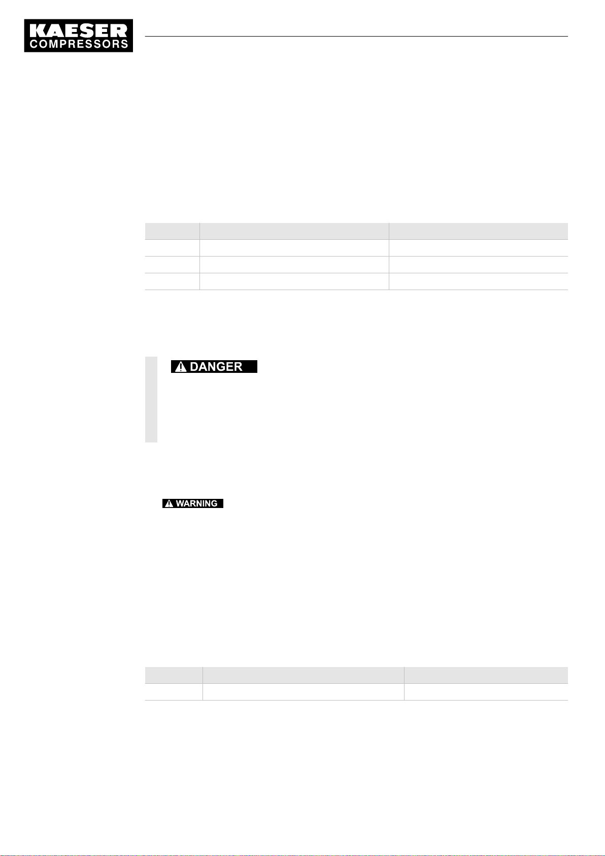
Warning notices indicate dangers that may result in injury when disregarded.
Warning notices indicate three levels of danger identified by the corresponding signal word:
Signal term Meaning Consequences of non-compliance
DANGER Warns of an imminent danger Will result in death or severe injury
WARNING Warns of a potentially imminent danger May result in death or severe injury
CAUTION Warns of a potentially dangerous situation May result in a moderate physical injury
Tab. 8 Danger levels and their definitions (personal injury)
Warning notices preceding a chapter apply to the entire chapter, including all sub-sections.
Example:
The type and source of the imminent danger is shown here!
The possible consequences of ignoring a warning are shown here.
If you ignore the warning notice, the "DANGER" signal word indicates a lethal or severe in‐
jury will occur.
➤ The measures required to protect yourself from danger are shown here.
Warning notes referring to a sub-section or the subsequent action are integrated into the procedure
and numbered as an action.
Example:
1.
The type and source of the imminent danger is shown here!
The possible consequences of ignoring a warning are shown here.
If you ignore the warning notice, the "WARNING" signal word indicates that a lethal or severe
injury may occur.
➤ The measures required to protect yourself from danger are shown here.
2. Always read and comply with warning instructions.
1.4.2 Potential damage warnings
Contrary to the warnings shown above, damage warnings do not indicate a potential personal in‐
jury.
Warning notices for damages are identified by their signal term.
Signal term Meaning Consequences of non-compliance
NOTICE Warns of a potentially dangerous situation Damage to property is possible
Tab. 9 Danger levels and their definition (damage to property)
Example:
Service Manual Controller
2
SIGMA CONTROL 2 SCREW FLUID 1.0.x.x No.: 9_9450 00 USE
Page 49

1 Regarding this Document
1.4 Symbols and labels
The type and source of the imminent danger is shown here!
Potential effects when ignoring the warning are indicated here.
➤ The protective measures against the damages are shown here.
➤ Carefully read and fully comply with warnings against damages.
1.4.3 Other alerts and their symbols
This symbol identifies particularly important information.
Material Here you will find details on special tools, operating materials or spare parts.
Precondition Here you will find conditional requirements necessary to carry out the task.
The conditions relevant to safety shown here will help you to avoid dangerous situations.
➤ This symbol denotes lists of actions comprising one stage of a task.
Operating instructions with several steps are numbered in the sequence of the operating steps.
Information referring to potential problems are identified by a question mark.
The cause is named in the help text ...
➤ ... as is a solution.
This symbol identifies important information or measures regarding the protection of the envi‐
ronment.
Further information Further subjects are introduced here.
No.: 9_9450 00 USE
Service Manual Controller
SIGMA CONTROL 2 SCREW FLUID 1.0.x.x
3
Page 50
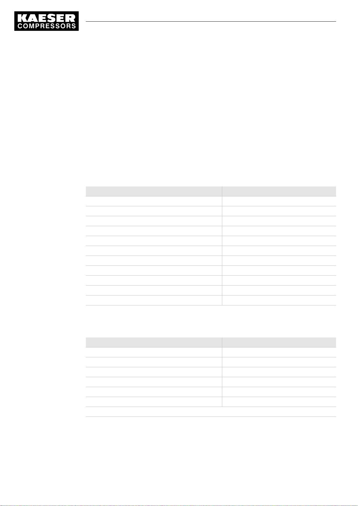
2 Technical Data
2.1 SIGMA CONTROL 2 Controller
2 Technical Data
2.1 SIGMA CONTROL 2 Controller
Industrial computer
■ Internal temperature monitoring
■ Internal undervoltage monitoring
■ Battery-buffered real-time clock
─ Battery life span more than 10 years
─ Battery replaceable
2.1.1 User interface with display, CPU and interfaces
User interface
Feature Value
Material Plastics
Width [in] 7.5
Height [in] 5.1
Depth [in] 1.8
Number of membrane keys 13
Number of LEDs 9
Degree of protection, control cabinet exterior IP 54
Degree of protection, control cabinet interior IP 20
Voltage [V] 24
Current [A] 0.3
Voltage source Input/output module
Tab. 10 User interface
Display
Feature Value
Graphical display [px] 255 x 128
Width [in] 3.2
Height [in] 1.6
Maximum number of lines/characters 8/30
Colors Black/white with gray levels
Lighting LED backlit
px ≙ pixel
Tab. 11 Display data
Service Manual Controller
4
SIGMA CONTROL 2 SCREW FLUID 1.0.x.x No.: 9_9450 00 USE
Page 51
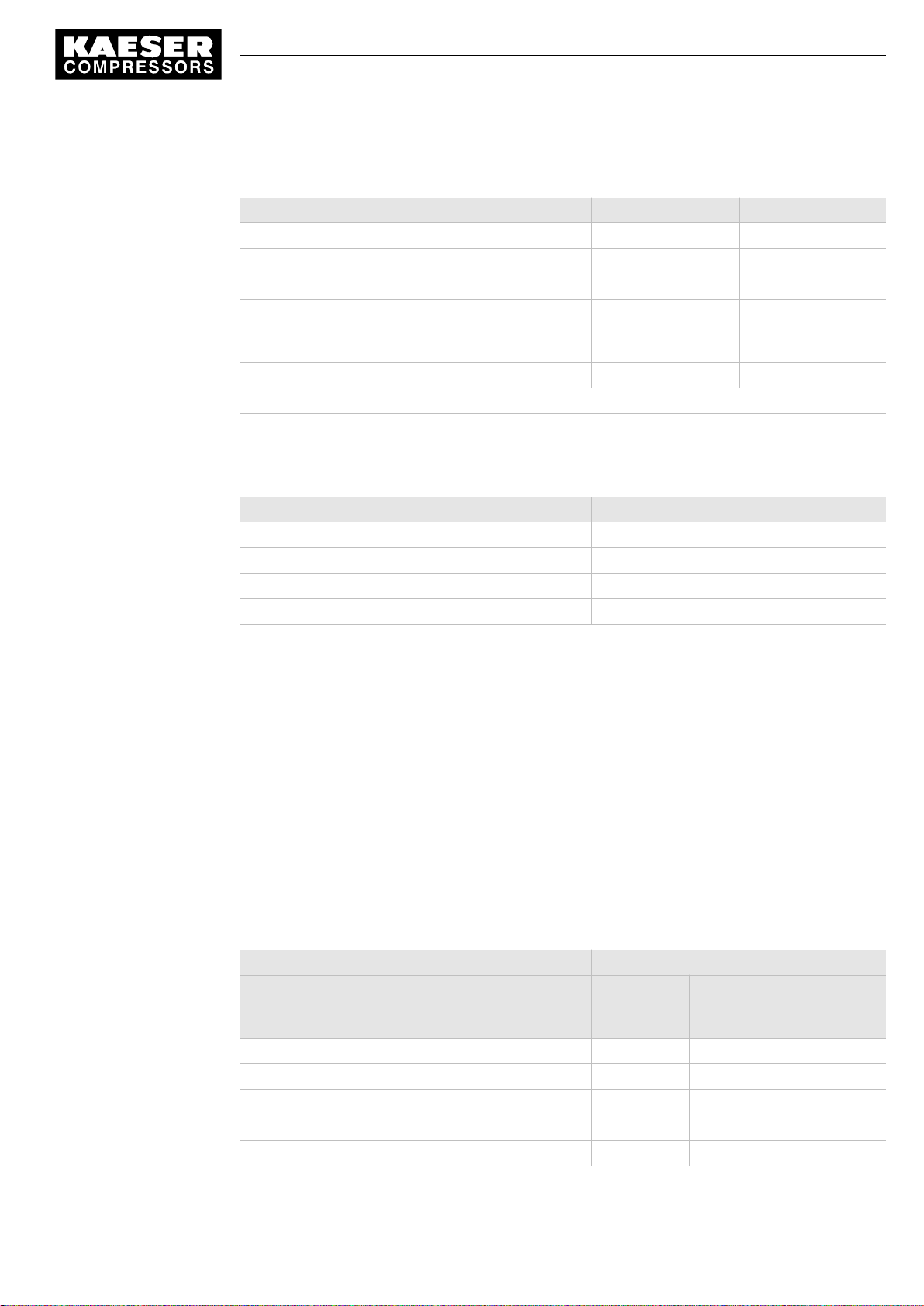
2 Technical Data
2.1 SIGMA CONTROL 2 Controller
Interfaces
Interface Connection Marking
Ethernet 10/100 Base T RJ 45 socket X1
IO bus 9-pole SUB-D pins X2
RS485–FC (USS interface) 9-pole SUB-D socket X3
COM modules,
slot for communications module
SD card, SD card slot SD/SDHC card X5
The positions of the interfaces X1–X5 are marked on the rear of the controller.
Tab. 12 Interfaces
Identification with RFID Equipment Card
Module optional for:
Profibus, Modbus,
Profinet, Devicenet
X4
Feature Value
Hardware on the SIGMA CONTROL 2 controller RFID write/read device
Hardware (external) KAESER Equipment Card
Recognition distance [in] Max. 2
Frequency [MHz] 13.56
Tab. 13 RFID
2.1.2 Input/output modules
There are three different types of input/output modules with different amounts of inputs and out‐
puts.
The actually available number of input/output modules depends on the machine type and the avail‐
able options.
Refer to the machine's wiring diagram for the input/output modules installed in your equipment.
Every input/output module is equipped with:
■ Internal temperature monitoring
■ Internal undervoltage monitoring
■ LED indication of operational status
IOM 1
Input/Output Input/output module 1
Digital input (DI), 24 VDC 4 10 2
Analog input current (AII), 0–20 mA – 1 2
Analog input resistor (AIR), PT100 – 1 3
Digital output relay (DOR), 250 VAC, 8 A 8 – –
Digital output transistor (DOT), 24 VDC, 0.5 A – 2 1
Internal, into
the control
cabinet
available in
parallel on
both sides
External, into
the compres‐
sor interior
No.: 9_9450 00 USE
Service Manual Controller
SIGMA CONTROL 2 SCREW FLUID 1.0.x.x
5
Page 52
2 Technical Data
2.1 SIGMA CONTROL 2 Controller
Input/Output Input/output module 1
Analog output current (AOI), 0–20 mA – – –
Tab. 14 SC2IOM-1
IOM 2
Input/Output Input/output module 2
Digital input (DI), 24 VDC 6 – 2
Analog input current (AII), 0–20 mA – 1 2
Analog input resistor (AIR), PT100 – 3 –
Digital output relay (DOR), 250 VAC, 8 A 4 – –
Digital output transistor (DOT), 24 VDC, 0.5 A – 2 2
Analog output current (AOI), 0–20 mA – 1 –
Internal, into
the control
cabinet
Internal, into
the control
cabinet
available in
parallel on
both sides
available in
parallel on
both sides
External, into
the compres‐
sor interior
External, into
the compres‐
sor interior
Tab. 15 SC2IOM-2
IOM 3
Input/Output Input/output module 3
Digital input (DI), 24 VDC 6 – 2
Analog input current (AII), 0–20 mA – 1 3
Analog input resistor (AIR), PT100 – 3 8
Digital output relay (DOR), 250 VAC, 8 A 8 – –
Digital output transistor (DOT), 24 VDC, 0.5 A – 1 1
Analog output current (AOI), 0–20 mA – 1 –
Tab. 16 SC2IOM-3
2.1.2.1 Power supply specifications
Power is provided by the power supply unit within the machine.
Feature Value
Rated power supply (stabilized) [V DC] 24
Current consumption SIGMA CONTROL 2
with IOM 1 [A]
Current consumption IOM 2 [A] 2,5
IOM ≙ input/output module
Internal, into
the control
cabinet
available in
parallel on
both sides
2,4
External, into
the compres‐
sor interior
Service Manual Controller
6
SIGMA CONTROL 2 SCREW FLUID 1.0.x.x No.: 9_9450 00 USE
Page 53
2 Technical Data
2.1 SIGMA CONTROL 2 Controller
Feature Value
Current consumption IOM 3 [A] 1,6
IOM ≙ input/output module
Tab. 17 Power supply specifications
2.1.2.2 Maximum cable lengths
Input/Output Conductor length [ft]
Analog input current (AII),
Analog input resistor (AIR)
Analog output current (AOI)
Digital input (DI),
Digital output relay (DOR)
Digital output resistor (DOT) < 100
< 100
< 330
Tab. 18 Cable lengths
2.1.2.3 Input/output modules – degree of protection
Feature Value
Degree of protection within the machine IP 54
Degree of protection within the control cabinet IP 20
Tab. 19 Degree of protection, IOM
2.1.2.4 Input/output modules – dimensions
Feature Value
Width [in] 4.9
Height [in] 9.8
Depth [in] 1.7
Tab. 20 IOM dimensions
2.1.3 Sensors
Pressure transducer
No.: 9_9450 00 USE
Feature Value
Output signal [mA] 0/4–20
Connection Twin cable
Tab. 21 Pressure transducer
Resistance thermometer
Feature Value
Sensing resistance (to DIN IEC 751) PT100
Service Manual Controller
SIGMA CONTROL 2 SCREW FLUID 1.0.x.x
7
Page 54

2 Technical Data
2.1 SIGMA CONTROL 2 Controller
Feature Value
Connection Twin cable
Tab. 22 Resistance thermometer
Service Manual Controller
8
SIGMA CONTROL 2 SCREW FLUID 1.0.x.x No.: 9_9450 00 USE
Page 55

3 Safety and Responsibility
3.1 Basic instructions
3 Safety and Responsibility
3.1 Basic instructions
This equipment has been tested and found to comply with the limits for a Class B digital de‐
vice, pursuant to part 15 of the FCC Rules.
These limits are designed to provide reasonable protection against harmful interference in a
residential installation. This equipment generates, uses and can radiate radio frequency ener‐
gy and, if not installed and used in accordance with the instructions, may cause harmful inter‐
ference to radio communications.
However, there is no guarantee that interference will not occur in a particular installation.
If this equipment does cause harmful interference to radio or television reception, which can
be determined by turning the equipment off and on, the user is encouraged to try to correct
the interference by one or more of the following measures:
➤ Close and lock the door of the equipment properly.
➤ Place the equipment as far as possible from the interfered radio or television receiver.
Changes or modifications not expressly approved by KAESER could void the user's authority
to operate the equipment.
This device complies with Industry Canada licence-exempt RSS standard(s).
Operation is subject to the following two conditions:
■ this device may not cause interference and
■ this device must accept any interference, including interference that may cause unde‐
sired operation of the device
SIGMA CONTROL 2 is manufactured to the latest engineering standards and acknowledged safety
regulations.
The safety regulations of the machine in which SIGMA CONTROL 2 is installed apply.
3.2 Specified use
SIGMA CONTROL 2 is solely intended for the control of machines in which SIGMA CONTROL 2 is
factory-installed. Any other use is considered incorrect. The manufacturer is not liable for any dam‐
ages that may result from incorrect use. The user alone is liable for any risks incurred.
➤ Adhere to the specifications given in these operating instructions and the machine's service
manual.
➤ Operate the machine only within its performance limits and under the permitted ambient condi‐
tions.
3.3 Improper use
No.: 9_9450 00 USE
Improper usage can cause damage to property and/or (severe) injuries.
➤ Use SIGMA CONTROL 2 only as intended.
➤ Do not use SIGMA CONTROL 2 to control other machines or products for which
SIGMA CONTROL 2 is not intended.
Service Manual Controller
SIGMA CONTROL 2 SCREW FLUID 1.0.x.x
9
Page 56
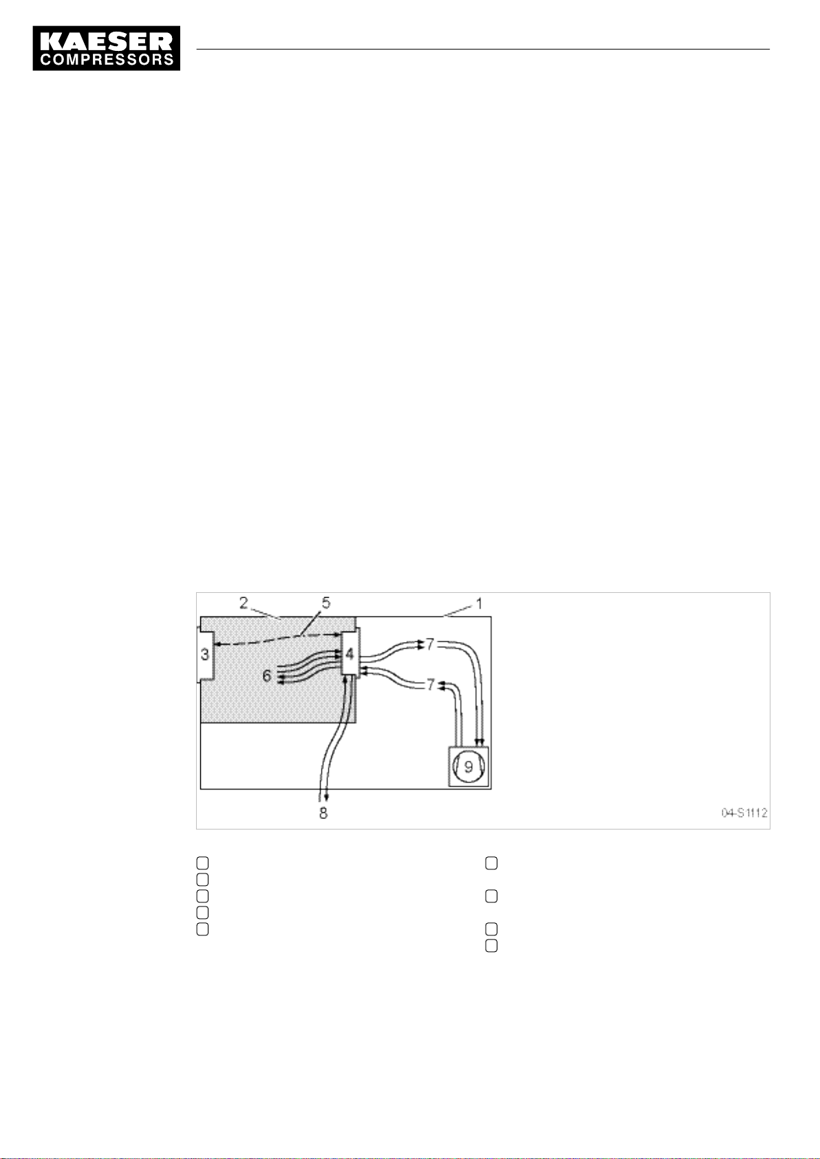
4 Design and Function
4.1 The controller
4 Design and Function
4.1 The controller
SIGMA CONTROL 2 controls, regulates, monitors, and protects the machine.
All parameters needed to operate KAESER rotary screw compressors can be set and displayed
using the controller. Various user-dependent password mechanisms protect the parameters.
Components
SIGMA CONTROL 2 comprises the following components:
■ Main Control System (MCS):
─ Industrial PC
─ Software for the control, regulation, and monitoring of the machine, for the display and mod‐
ification of settings and for communication.
─ User interface with backlit display, touch keys, and interfaces.
─ Radio Frequency Idenfication (RFID):
Identification with the KAESER RFID Equipment Card
─ Slot for customer interface; optional communications module
─ SD card slot for SD/SDHC cards:
Manual loading of updates with an SC card, reading or recording process data
■ Input-Output-Module (IOM):
Modules with digital and analog inputs and outputs with their own power supply.
10
Fig. 2 System structure
1 Machine enclosure
2 Control cabinet
3 SIGMA CONTROL 2
4 Input/output module
5 IO bus
Function
The control and regulating function allows:
■ Automatic changeover of the machine from LOAD to IDLE or STANDSTILL.
Service Manual Controller
SIGMA CONTROL 2 SCREW FLUID 1.0.x.x No.: 9_9450 00 USE
6 Inputs/outputs in the interior of the control
cabinet
7 Inputs/outputs in the interior of the com‐
pressor
8 Inputs/outputs for external sensors
9 Compressor
Page 57
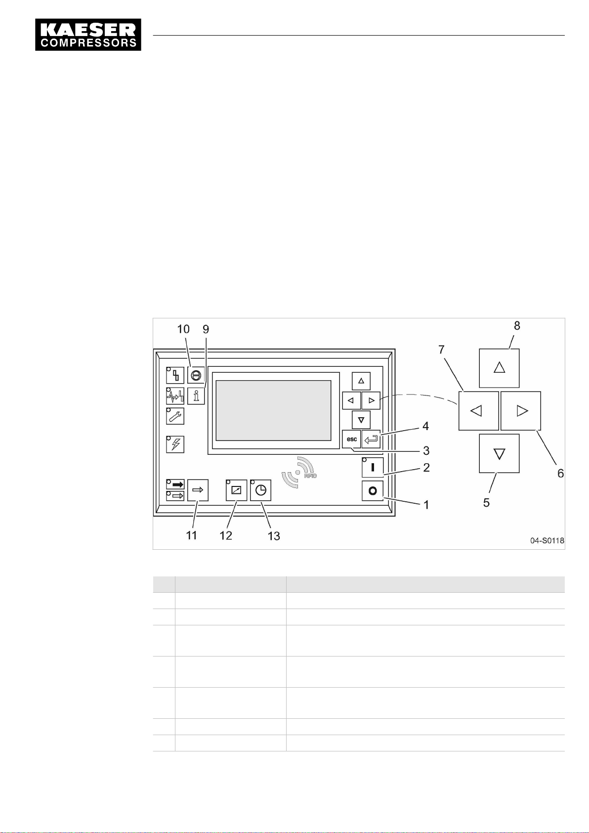
4 Design and Function
4.2 Operating panel SIGMA CONTROL 2
■ Optimum utilization of the drive motor in relation to the user's actual air demand.
■ Automatic restart of the machine after a power failure (can be deactivated).
The monitoring function allows:
■ Supervision of all maintenance-relevant components via the maintenance interval counters.
■ Display of warning and maintenance messages for due maintenance on the display of
the SIGMA CONTROL 2.
The protective function allows:
■ Automatic machine shutdown on alarms that may lead to damage to the machine, e.g. overcur‐
rent, overpressure, overtemperature.
4.2 Operating panel SIGMA CONTROL 2
Keys
No.: 9_9450 00 USE
Fig. 3 Keys – overview
Item Name Function
1 «OFF» Switch off the machine.
2 «ON» Switch on the machine.
3 «Escape» Returns to the next higher menu option level.
4 «Enter» Jumps to the selected menu option.
5 «DOWN» Scrolls down the menu options.
6 «Right» Jumps to the right.
7 «Left» Jumps to the left.
Service Manual Controller
SIGMA CONTROL 2 SCREW FLUID 1.0.x.x
Exits the edit mode without saving.
Exits the edit mode and saves.
Reduces a parameter value.
11
Page 58
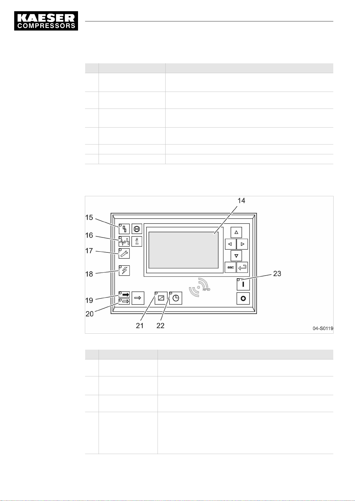
4 Design and Function
4.2 Operating panel SIGMA CONTROL 2
Item Name Function
8 «UP» Scrolls up the menu options.
9 «Events and information» Operating mode:
10 «Acknowledgement» Acknowledges alarms and warning messages.
11 «LOAD/IDLE» Toggles the compressor between LOAD and IDLE operating
12 «Remote control» Switches remote control on and off.
13 «Shift clock» Switches clock control on and off.
Tab. 23 Keys
Indicators
Increases a parameter value.
Displays the event memory.
If permissible: Resets the fault counter (RESET).
modes.
12
Fig. 4 Indicators
Item Name Function
14 Indicator field or dis‐
play
15
Fault
16
Communication
17
Warning
Service Manual Controller
SIGMA CONTROL 2 SCREW FLUID 1.0.x.x No.: 9_9450 00 USE
Graphic display with 8 lines and 30 characters.
Flashes red when an alarm occurs.
Lights continuously when acknowledged.
Continuous red illumination if a communication connection (Ethernet,
USS, COM modules) has a fault.
Flashes in yellow in the following events:
■ maintenance work due,
■ Warning message
Lights continuously when acknowledged.
Page 59
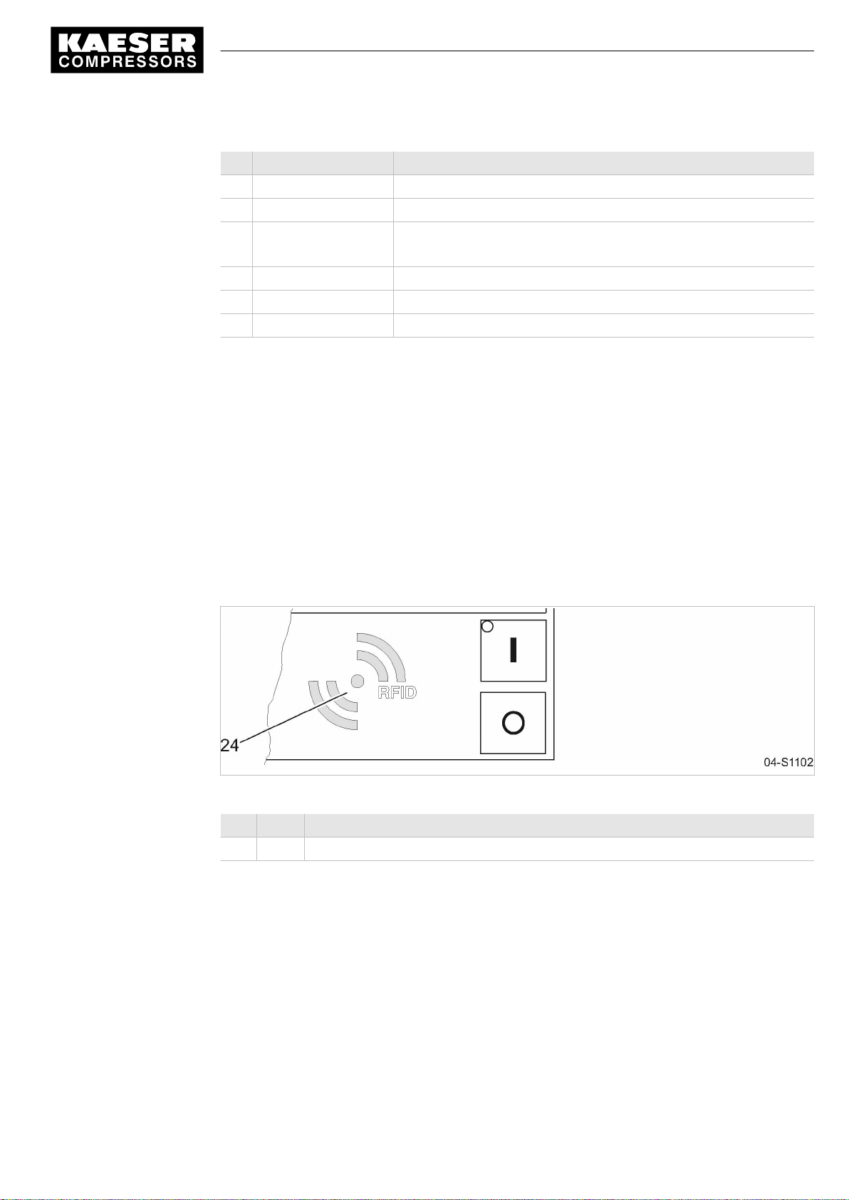
4 Design and Function
4.3 Display
Item Name Function
18
Control voltage
19
LOAD
20
IDLE
21
Remote control
22
Shift clock
23
Machine ON
Tab. 24 Indicators
RFID sensor field
RFID is the abbreviation for “Radio Frequency Indentification” and enables the identification of per‐
sons or objects.
Placing a suitable transponder in front of the RFID sensor field of the controller will automatically
activate the communication between transponder and SIGMA CONTROL 2 .
A suitable transponder is the EQUIPMENT CARD. Two of them have been provided with the ma‐
chine.
Lights green when the power supply is switched on.
Lights green when the compressor is running under LOAD.
Lights green when the compressor is running in IDLE.
Flashes when the «LOAD/IDLE» toggle key is pressed.
The LED lights when the machine is in remote control.
The LED lights when the machine is in clock control.
Lights green when the machine switched on.
Typical application:
■ Users log on to the machine.
(no manual input of the password required.)
Fig. 5 RFID sensor field
Item Name Function
24 RFID RFID sensor field for the communication with a suitable RFID transponder.
Tab. 25 RFID sensor field
Further information More information about the use of RFID technology is provided in the SIGMA CONTROL 2 operat‐
ing manual.
No.: 9_9450 00 USE
4.3 Display
Use the display to read information and to enter data. The display comprises 8 lines, each of
30 characters.
During operation, the display will indicate the operating mode.
Service Manual Controller
SIGMA CONTROL 2 SCREW FLUID 1.0.x.x
13
Page 60

4 Design and Function
4.3 Display
Pressing «Enter» or one the arrow keys opens the main menu. Here, you can set the language to
be used for the display of texts or open the various submenus.
4.3.1 Operating mode
8 8 p s i 0 8 : 1 5 1 7 6 ° F
·········
off
·········
Key – off ¦ pA – off
Run 2500 h ¦ load 2490 h
Maintenance in: 500 h
Header
Current operating mode
Operating parameters
Operating parameters
The header is the topmost line on the display. It is always shown as white text on a black back‐
ground.
The following parameters are displayed permanently on the title bar:
■ Working pressure
■ Time
■ Airend discharge temperature
Line 3: Operational state
Depending on settings, either the current state of the machine or menu text is shown in line 3.
Lines 5 and 6: Machine state
The following parameters with their current values are displayed in lines 5 and 6:
■ Remote control yes/no
■ Time control yes/no
■ Pressure control
■ The hours during which the machine was activated
■ The hours during which the machine ran in operating mode LOAD.
4.3.2 Main menu
14
8 8 p s i 0 8 : 1 5 1 7 6 ° F
········· Deutsch ·········
▶1 Status
▶2 Performance data
▶3 Operating data
▶4 Maintenance
▶5 Configuration
▶6 Compressor clock
Service Manual Controller
SIGMA CONTROL 2 SCREW FLUID 1.0.x.x No.: 9_9450 00 USE
Language
Submenu
Submenu (here: active line)
Submenu
Submenu
Submenu
Submenu
Page 61

4 Design and Function
4.3 Display
Description
The main menu is the top menu level. You open the individual submenus in the main menu.
A scrollbar appears at the right side of the display if you open a menu with more than 6 lines. It
represents the currently visible portion of the menu. A short scrollbar thus indicates that the opened
menu is very long as only a small portion can be displayed.
The image above provides an example for the appearance of the main menu (without scrollbar).
Numbering
Each menu is numbered.
Because the access to certain menus is restricted to specific access rights, not all menus may be
shown.
For example, you can recognize subordinate menus in the menu structure by the number preced‐
ing their designation. The menu structure is explained in chapter 4.5.2.
Active line
The active line is always shown as white text on a dark background. Do not confuse this with the
header which is also shown with white lettering on a black background.
Press «Enter» to open a menu in the active line. This opens the selected menu.
Here, you can change parameters.
Further information For the setting of parameters see chapter 4.3.3.
4.3.3 Setting parameters
In order to set a parameter in the active line of the selected menu, you must always switch to
setting mode.
You move to setting mode by:
pressing «Enter». The value of the parameter will flash indicating that it can be changed.
Changing parameters
Press «Enter». The value of the parameter will flash indicating that it can be changed.
The «Enter» key affects only the active line.
In some lines, you can change more than a single parameter.
In this case, you must first select the specific parameter with the «Left» or «Right» keys.
Resetting current parameters
No.: 9_9450 00 USE
In order to reset current parameters to Zero, activate the check box for Reset in the active line of
the display.
First, press «Enter» to switch into setting mode. The check box for Reset will flash.
You then press «UP». The check box is activated and flashes.
Press «Enter» to save the settings.
The parameters no longer flash and are reset. The check box for Reset is again deactivated.
Check boxes for Reset Status
☒ activated
Service Manual Controller
SIGMA CONTROL 2 SCREW FLUID 1.0.x.x
15
Page 62
4 Design and Function
4.4 Access rights
Check boxes for Reset Status
☐ deactivated
Tab. 26 Reset check box status
4.3.4 Activating keys with check boxes
Certain keys of the SIGMA CONTROL 2 are locked by default. Activate the corresponding check
boxes in the active line of the display to unlock these keys.
First, press «Enter» to switch into setting mode. The check box will flash.
You then press «UP». The check box is activated and flashes.
Press again «Enter» to save the settings.
The display line no longer flashes and the key is activated.
Proceed correspondingly to deactivate a key.
Check box Status
☑ activated
☐ deactivated
Tab. 27 Check box status
4.4 Access rights
Access to the controller is governed by the user name combined with a password.
Users log on using an RFID Equipment Card by default. Alternatively, you can manually enter the
user name and the password.
Throughout this operating manual, the RFID Equipment Card will be simply called the "Equip‐
ment Card".
When the controller is switched on, the lowest level of access (level 0) is activated.
You have access to a further level: Level 2.
In level 2, you can display and specify further parameters and, for instance, reset the system pres‐
sure or the maintenance counters.
The access level will automatically return to level 0 after 10 minutes without any key being pressed.
4.4.1 Secure storage of the RFID Equipment Cards
You will receive 2 RFID Equipment Cards with each machine.
If both Equipment Cards are misplaced, you can register a new Equipment Card only after entering
the user name and the password. A new Equipment Card may registered by an authorized
KAESER service representative, subject to a fee, if the user name and the password are lost.
16
4.5 Menus – overview
4.5.1 Operating mode
After the machine is switched on, details of the software are displayed, for example,
Service Manual Controller
SIGMA CONTROL 2 SCREW FLUID 1.0.x.x No.: 9_9450 00 USE
Page 63

4 Design and Function
4.5 Menus – overview
C o m p r e s s o r
Compressor PN Compressor SN
Compressor EN
SIGMA CONTROL 2 MCS
PN: SN:
Software:
Subsequently, the software is loaded and the current operating mode is displayed (example):
8 8 p s i 0 8 : 1 5 1 7 6 ° F
·········
off
·········
Key – off ¦ pA – off
Run 2500 h ¦ load 2490 h
Maintenance in: 500 h
Material number and serial number of the machine
Equipment number of the machine
MCS: Main Control System
Material number and serial number of the controller
Software version
Current operating mode
Operating parameters
Operating parameters
The following parameters are displayed:
■ Operating mode of the machine
■ Information to the «LOAD/IDLE» keys, «Remote control» or «Timer»
■ Value for Setpoint pressure pA
■ Number of operating hours and hours of the machine being in LOAD mode
The operations menu provides the most important parameters during the machine's operation.
4.5.2 Menu structure
Pressing «Enter» or one the arrow keys opens the main menu.
In the main menu, you can:
■ Retrieve displayed information
■ Enter customer-specific settings
The menus shown require access level 2.
No.: 9_9450 00 USE
Service Manual Controller
SIGMA CONTROL 2 SCREW FLUID 1.0.x.x
17
Page 64

4 Design and Function
4.5 Menus – overview
Main menu
Navigation Function/submenu
1 Status ■ 1.1 Messages
─ Status report
─ current Warnings
current Alarms
■ 1.2 Statistics
■ 1.3 Current pressure control
■ 1.4 Current operating mode
For details of the
“Status menu”.
2 Performance data Display of the following Performance data :
■ System pressure pNloc
■ Internal pressure pi
■ ADT
■ Oil separator
■ Starting temperature
■ Motor temperature
■ MCS Temperature
■ First IOM ......... Sixth IOM
3 Operating data ■ Load valve ON
■ 3.1 Operating hours
─ Compressor
─ ON LOAD
─ Motor
─ Compressor block
─ SIGMA CONTROL 2
4 Maintenance ■ Oil filter
■ Oil separator
■ Oil change
■ Air filter
■ Valve inspection
■ Belt/coupling inspection
■ Bearing lube
■ Motor bearings
■ Fan bearing
■ Electrical equipment
5 Configuration For details of the
table 30 “Configuration menu”.
6 Compressor clock Entering weekdays and times:
■ Switching points 01 ......... 10
< Status >
menu, see table 29
< Configuration >
menu, see
18
Service Manual Controller
SIGMA CONTROL 2 SCREW FLUID 1.0.x.x No.: 9_9450 00 USE
Page 65
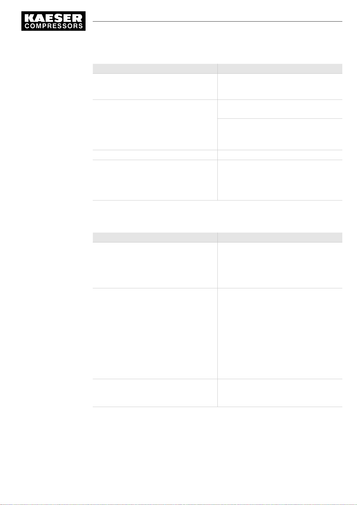
4 Design and Function
4.5 Menus – overview
Navigation Function/submenu
7 User ■ Name
Password:
■ Current access level:
8 Communication ■ 8.1 Ethernet
■ 8.2 Com-Module
■ Key remote
9 Machine test ■ 9.1 TÜV inspection
10 Components ■ 10.1 Compressor motor
Tab. 28 Menu structure
4.5.2.1 Menu: 1 Status
Navigation Function/submenu
1.1 Messages ■ 1.1.1 Current messages
1.2 Statistics ■ Load overall
1.3 Current pressure control ■ Cut-out press.
For details of the
table 33 “Communication menu”.
─ 10.1.1 Power switching
For details of the
table 35 “Components menu”.
■ 1.1.2 Message history
─ 1.1.2.1 Compressor messages
─ 1.1.2.2 Diagnostic messages
─ 1.1.2.3 System messages
■ Pressure actual value pNloc
■ Internal pressure
■ Motor starts
■ Motor starts /d
■ Motor starts /h
■ Motor starts T↓
■ Last load run
■ Last idle run
■ Last motor OFF
■ Pressure actual value
■ Setpoint pressure
< Communication >
< Components >
menu, see
menu, see
No.: 9_9450 00 USE
Service Manual Controller
SIGMA CONTROL 2 SCREW FLUID 1.0.x.x
19
Page 66

4 Design and Function
4.5 Menus – overview
Navigation Function/submenu
1.4 Current operating mode ■ Compressor ON
Tab. 29 Menu Status
4.5.2.2 Menu: 5 Configuration
Navigation Function/submenu
5.1 General ■ Model
5.2 Pressure control ■ 5.2.1 Pressure sensors
Load control
■ Control Mode
Idle period
■ Acknowledgement
■ Time
■ Date format
■ Time format
■ Unit of pressure
■ Temperature unit
5.1.1 System information
■ Compressor
─ Part number
─ Serial number
─ Equipment number
■ SIGMA CONTROL 2 MCS
─ Part number
─ Serial number
─ Software
■ 5.2.2 Pressure settings
■ 5.2.3 Load control
■ 5.2.4 Pressure actual value
20
For details of the
see table 31 “Pressure control menu”.
5.3 Control Mode
5.4 Compressor start ■ Autostart
Service Manual Controller
SIGMA CONTROL 2 SCREW FLUID 1.0.x.x No.: 9_9450 00 USE
■ Dryer
■ 5.3.1 Venting period
■ 5.3.3 DUAL
■ 5.3.4 QUADRO
■ 5.4.1 Compressor ON
■ 5.4.2 Compressor OFF
■ Back pressure
< Pressure control >
menu,
Page 67

4 Design and Function
4.5 Menus – overview
Navigation Function/submenu
5.5 Acknowledgement ■ Remote mode
■ Key remote
■ current
■ RC ack
5.6 ADT ■ AIR 1.00
■ Conductor correction:
■ ADT rise dT/dt
■ 5.6.1 T-Switch ADT
5.7 I/O periphery ■ 5.7.1 DO functions
■ 5.7.2 Quantities
■ 5.7.3 External messages
Tab. 30 Menu Configuration
Menu: 5.2 Pressure control
Navigation Function/submenu
5.2.1 Pressure sensors
5.2.2 Pressure settings ■ pRV
5.2.3 Load control ■ local mode
For details of the
table 32 “I/O periphery menu”.
■ System pressure pNloc
■ AII 1.00
■ AOI2.00
■ Internal pressure pi
■ AII 1.01
■ AOI2.00
■ 5.2.1.1 p-Switch pN
■ 5.2.1.2 p-Switch pi
■ Pressure rise
■ Nominal pressure
■ Setpoint pressure pA
■ Setpoint pressure pB
■ System pressure low
■ Cut-in pressure min
■ Remote mode
■ Key remote
■ pA/pB cycle
■ pA/pB RC
■ loc.-loadRC
■ Key idle
< I/O periphery >
menu, see
No.: 9_9450 00 USE
Service Manual Controller
SIGMA CONTROL 2 SCREW FLUID 1.0.x.x
21
Page 68

4 Design and Function
4.5 Menus – overview
Navigation Function/submenu
5.2.4 Pressure actual value ■ Pressure actual value pNloc
Tab. 31 Menu Pressure control
Menu: 5.7 I/O periphery
Navigation Function/submenu
5.7.1 DO functions ■ Controller ON
5.7.2 Quantities ■ Display 1 (p), Display 2 (p)
5.7.3 External messages ■ External message 1 ......... External
■ AII 1.02
■ current pNloc
■ Compressor ON
■ Motor running
■ IDLE
■ ON LOAD
■ Group alarm
■ Group warning
■ Remote mode
■ Clock active
■ EMERGENCY STOP
■ 5.7.1.1 Clock contact
─ Switching points 01 ......... 10
■ Display 3 (T), Display 4 (T)
■ Display 5 (I), Display 6 (I)
message 6
Tab. 32 Menu I/O periphery
22
Service Manual Controller
SIGMA CONTROL 2 SCREW FLUID 1.0.x.x No.: 9_9450 00 USE
Page 69

4 Design and Function
4.5 Menus – overview
4.5.2.3 Menu: 8 Communication
Navigation Function/submenu
8.1 Ethernet ■ 8.1.1 IP configuration
─ IP address
─ Subnet mask
─ Gateway
─ DNS Server 1
─ DNS Server 2
■ 8.1.2 Connections
─ 8.1.2.1 SIGMA CONTROL 2
For details of the
>
menu, see table 34 “SIGMA CONTROL 2
menu”.
■ 8.1.2 Connections
─ Restart
─ Timeout
─ Cycle time
■ 8.1.3 E-mail
─ active:
─ Compressor number:
─ Sender address:
─ Sender name:
─ Contact telephone:
─ Receiver address:
─ SMTP Server:
─ User name:
─ Port
─ Interval time
8.2 Com-Module ■ 8.2.1 PROFIBUS
─ Status Run
─ Start Com-Module:
Slave no.:
─ Bus alarm
Start td:
Timeout:
< SIGMA CONTROL 2
No.: 9_9450 00 USE
Tab. 33 Menu Communication
Service Manual Controller
SIGMA CONTROL 2 SCREW FLUID 1.0.x.x
■ 8.2.2 MODBUS
─ Status Run
─ Start Com-Module:
Slave no.:
─ Bus alarm
Start td:
Timeout:
23
Page 70

4 Design and Function
4.6 Operating modes and control modes
4.5.2.4 Menu: 8.1.2.1 SIGMA CONTROL 2
Navigation Function/submenu
8.1.2.1 SIGMA CONTROL 2 ■ Mode:
Tab. 34 Menu SIGMA CONTROL 2
4.5.2.5 Menu: 10 Components
Navigation Function/submenu
10.1 Compressor motor
■ Port
■ Communication partner
IP address
■ 10.1.1 Power switching
─ 10.1.1.1 Star-delta start
─ 10.1.1.2 DOL start
─ 10.1.1.3 High-voltage cell
─ 10.1.1.4 SFC USS Micromaster
─ 10.1.1.5 SFC USS Sinamics
Tab. 35 Menu Components
4.6 Operating modes and control modes
4.6.1 Operating modes
The machine operates in the following modes:
■ LOAD:
The inlet valve is open. The airend delivers compressed air to the distribution network.
The drive motor runs under full load.
■ IDLE:
The inlet valve is closed. The minimum pressure/check valve shuts off the oil separator from
the distribution network. The venting valve is open.
A small volume of air circulates through the bleed hole in the inlet valve, through the airend
and back to the inlet valve via the venting valve.
The drive motor runs without load and draws little current.
■ STANDSTILL:
The inlet valve is closed. The minimum pressure/check valve shuts off the oil separator from
the distribution network. The venting valve is open.
The drive motor is stopped.
Option C1
■ MODULATING CONTROL:
With the help of a control valve (the proportional controller) the degree of opening of the inlet
valve is steplessly varied in response to the air demand. The airend delivers compressed air to
the distribution network.
The load and power consumption of the drive motor rises and falls with the air demand.
The regulating valve is factory set. The setting should not be changed without consultation with
an authorized KAESER service representative.
24
Service Manual Controller
SIGMA CONTROL 2 SCREW FLUID 1.0.x.x No.: 9_9450 00 USE
Page 71
4 Design and Function
4.6 Operating modes and control modes
4.6.2 Control modes
Using the selected control mode, the controller switches the machine between its various opera‐
tional states in order to compensate for air being drawn of by consumers and maintain system
pressure between the set minimum and maximum values. The control mode also rules the degree
of energy efficiency of the machine.
The machine-dependant venting phase between the LOAD and STANDSTILL operating modes en‐
sures load changes at minimum material stresses.
The controller SIGMA CONTROL 2 can operate in the following modes:
■ DUAL
■ QUADRO
■ VARIO
■ CONTINUOUS
■ DYNAMIC
Energy-efficient control modes for various applications:
Application Recommended
Compressed air station with one machine or several machines with com‐
parable delivery
Machine for peak load in a compressed air station DUAL
Machine for intermediate load in a compressed air station VARIO
Machine for basic load in a compressed air station QUADRO
Tab. 36 Energy-efficient control modes
The SIGMA CONTROL 2 is factory set to DUAL control mode unless specifically ordered other‐
wise.
DUAL
In the DUAL control mode, the machine is switched back and forth between LOAD and IDLE to
maintain the machine working pressure between the preset minimum and maximum values. When
maximum pressure is reached, the machine switches to IDLE. When the preset
elapsed the machine switches to STANDSTILL.
The
idling time
The shorter the
is factory preset according to the maximum starting frequency of the drive motor.
idling time
setting, the sooner (and more frequently) the drive motor is stopped.
control mode
VARIO
idling time
has
No.: 9_9450 00 USE
QUADRO
In contrast to the DUAL regulating mode, the machine will switch from LOAD to STANDSTILL in
QUADRO mode after periods with low compressed air consumption.
After periods with a high compressed air consumption, the machine will switch from LOAD to
STANDSTILL after passing through IDLE.
In this control mode, the controller requires two specified times: The
standstill time
The shorter these times are set, the sooner (and more frequently) the drive motor is stopped.
Service Manual Controller
SIGMA CONTROL 2 SCREW FLUID 1.0.x.x
.
running time
and the
idle/
25
Page 72

4 Design and Function
4.6 Operating modes and control modes
VARIO
The VARIO mode is based on the DUAL control mode. The difference to DUAL is that the
time
is automatically lengthened or shortened to compensate for higher or lower machine starting
frequencies.
CONTINUOUS
In the DUAL control mode, the machine is switched back and forth between LOAD and IDLE to
maintain the machine working pressure between the preset minimum and maximum values. When
maximum pressure is reached, the machine switches to IDLE. The motor is not stopped, i.e. the
machine does not switch to STANDSTILL.
DYNAMIC
In contrast to the DUAL regulating mode, the machine will switch from LOAD to STANDSTILL in
DYNAMIC mode at low drive motor temperature.
And from LOAD via IDLE to STANDSTILL at a high drive motor temperature.
The lower the drive motor temperature, the sooner (and, therefore, more often and longer) it is
stopped.
4.6.3 Frequency-controlled drive (SFC)
The frequency converter compares the actual network pressure with a target value and adjusts the
speed of the drive motor, and thereby the delivery of the compressor, accordingly.
The speed of the airend determines the rate of compressed air delivery and the working pressure.
If air consumption rises, the frequency converter increases motor speed and therefore increases
the volume of air delivered.
If air consumption drops, the converter reduces motor speed and therefore reduces the volume of
air delivered.
The network pressure remains constant – within the control range of the converter - regardless of
fluctuating air demand.
idling
26
If network pressure exceeds the target value:
Outside the frequency converter's range of control the machine reverts to the selected control
mode.
DUAL:
The minimum controllable speed is reached and the machine switches to IDLE. The drive motor
runs unloaded with low power consumption.
When the idle period has elapsed, the machine switches to STANDSTILL.
VARIO/QUADRO/CONTINUOUS:
The minimum controllable speed is reached and, depending on the air demand at the time, the ma‐
chine switches either to IDLE or to STANDSTILL.
DYNAMIC:
The minimum controllable speed is reached and, depending on the air temperature of the drive mo‐
tor, the machine switches either to STANDSTILL or to IDLE.
Service Manual Controller
SIGMA CONTROL 2 SCREW FLUID 1.0.x.x No.: 9_9450 00 USE
Page 73

4 Design and Function
4.7 MODULATING control
If network pressure falls below the set-point:
The frequency converter runs the motor up to a speed at which air delivery matches the air de‐
mand.
The inlet valve opens and the machine delivers compressed air.
The converter varies the speed of the drive motor according to the air demand. The power con‐
sumption of the drive motor rises and falls according to air demand.
4.7 MODULATING control
With the help of a mechanical control valve (the proportional controller), the opening and closing of
the inlet valve is continuously varied in relation to the actual air demand. The airend delivers com‐
pressed air to the distribution network.
The load and power consumption of the drive motor rises and falls with the air demand.
To ensure optimal control on large compressors, the control air for the proportional controller is tak‐
en from an external air receiver.
No.: 9_9450 00 USE
Service Manual Controller
SIGMA CONTROL 2 SCREW FLUID 1.0.x.x
27
Page 74

5 Installation and Operating Conditions
5.1 Maintaining ambient conditions
5 Installation and Operating Conditions
5.1 Maintaining ambient conditions
➤ Follow the instructions in the machine's service manual.
5.2 Installation conditions
The installation and operating conditions depend the machine into which the controller is installed.
UV radiation!
Direct sunlight (UV radiation) can destroy the display screen.
➤ Do not allow the display screen to be subjected to direct sunlight.
➤ See the machine's operating manual for required conditions.
28
Service Manual Controller
SIGMA CONTROL 2 SCREW FLUID 1.0.x.x No.: 9_9450 00 USE
Page 75
6 Installation
6.1 Reporting Transport Damage
6 Installation
6.1 Reporting Transport Damage
1. Check the machine for visible and hidden transport damage.
2. Inform the carrier and the manufacturer in writing of any damage without delay.
6.2 Machine identification
If the machine is run in sequenced operation its identification as detailed in the installation diagram
is to be taken into account.
Identifying the machine for operation in remote mode.
➤ Attach the following notice to warn of remote machine operation (suggestion):
Remote control: danger of unexpected starting!
➤ Make sure the power supply disconnecting device is switched off before commencing any
work on the machine.
Tab. 37 Machine identification
➤ Label the starting device in the remote control center as follows (suggestions):
Remote control: danger of unexpected starting!
➤ Before starting, make sure that no one is working on the machine and that it can be safely
started.
Tab. 38 Remote control identification
Identifying the machine for clock control mode operation
➤ Attach the following notice to warn of remote machine operation (suggestion):
Clock control: danger of unexpected starting!
➤ Make sure the power supply disconnecting device is switched off before commencing any
work on the machine.
No.: 9_9450 00 USE
Tab. 39 Machine identification
Service Manual Controller
SIGMA CONTROL 2 SCREW FLUID 1.0.x.x
29
Page 76

7 Initial Start-up
7.1 Outline
7 Initial Start-up
7.1 Outline
SIGMA CONTROL 2 was designed and developed for a number of applications. Potential settings
are correspondingly varied.
It is possible that only a few of these settings are needed for the initial start-up. This depends on
the application.
The following sections explain the large number of practical applications, but only one
Configuration is relevant for a specific use.
7.2: Configuring the controller (display format, units, languages, etc.)
7.3: Matching the pressure parameters of the machine and possible modules
7.4: Configuring machine start and stop
7.5: Activating and setting up the control modes
7.6: Configuring the machine for local mode
7.7: Configuring the machine for master control
7.8: Configuring e-mail
7.9: Configuring input and output signals
7.10: Configuring the compressed air outlet temperature
7.11: Activating remote acknowledgement
7.12: Linking to an external pressure transducer
7.13: Activating the energy-saving mode for the refrigeration dryer
7.14: Machine commissioning
7.2 Configuring the controller
All controller settings are explained in detail in the following sections. The most common set‐
tings are summarized for experienced users in the front of this manual.
➤ Carry out settings as required:
■ 7.2.1: Selecting menu options (introduction)
■ 7.2.2: Changing the display language
■ 7.2.4: Entering and displaying passwords
■ 7.2.5: Creating additional user names
■ 7.2.6: Setting up time and date
■ 7.2.7: Setting display formats (date, time, units of pressure and temperature)
■ 7.2.8: Activating summer/winter time
■ 7.3.3: Activating/deactivating the «IDLE» key
7.2.1 Selecting menu options
All menu options can be selected with the «DOWN», «UP» and «Enter» keys.
Example: Selecting the < Configuration ➙ General > menu option
Precondition The display shows the operating mode.
30
Service Manual Controller
SIGMA CONTROL 2 SCREW FLUID 1.0.x.x No.: 9_9450 00 USE
Page 77

7 Initial Start-up
7.2 Configuring the controller
1. Press «Enter».
The main menu is displayed.
2. Press the «UP» or «DOWN» key until
3. In order to open the
4. Use the «DOWN» or «UP» keys to select a submenu in the
>
or
< Pressure control >
5. Press «UP» repeatedly until
6. Press «Enter».
The current menu is the
7. Use the «DOWN» or «UP» keys to select a menu option in the
System information >
7.2.2 Changing the display language
The controller can display text messages in the following languages:
< Configuration >
for instance.
General
< General >
for instance.
Configuration
menu, press «Enter» once.
is displayed as active line.
< Configuration >
is displayed as active line.
submenu in the
< Configuration >
menu.
< General >
menu,
submenu,
< General
<
Bulgarian English
(USA)
Chinese Estonian Italian Polish Spanish
Chinese
(Taiwan)
Danish French Korean Romanian Czech
German French
English Greek Dutch Swedish ...
Tab. 40 Language diversity
Some of the units, as well as clock and date format, will be adjusted according to the language
selected.
Precondition The display shows the operating mode.
1. Press «Enter».
The main menu is displayed.
2. Press «UP» repeatedly until the specified language is displayed as active line.
3. Use the «Enter» key to switch to setting mode.
The currently set language flashes.
4. Use the «DOWN» or «UP» keys to select the desired language.
5. Press «Enter» to accept the setting.
6. Press «Escape» repeatedly to return to the main menu.
The display texts are now in the selected language.
Finnish Japanese Portuguese Spanish
(Canada)
Indonesian Norwegian Slovenian
(South-America)
Croatian Russian Turkish
No.: 9_9450 00 USE
7.2.3 Access rights with equipment card
Use the Equipment Card to quickly and easily check the advanced access rights to the
SIGMA CONTROL 2.
Service Manual Controller
SIGMA CONTROL 2 SCREW FLUID 1.0.x.x
31
Page 78

7 Initial Start-up
7.2 Configuring the controller
Advanced access rights:
■ read additional data
■ change other settings
1. Hold the Equipment Card in front of the controller's reader.
(see also chapter 4.2)
Your user name and access level will be displayed.
2. Press «Enter» to confirm the access right.
The Equipment Card is damaged or lost.
➤ Manually enter the user name and password (see also the following chapter).
7.2.4 Access right via manual input
Entering the user name
Precondition The display shows the operating mode.
1. Press «Enter».
The main menu is displayed.
2. Use «DOWN» to select the
The
Name
line is displayed as being active.
8 8 p s i 0 8 : 1 5 1 7 6 ° F
7 User
Name : Citizen4
Password: : ****************
Login
·········
Current access level: 0
3. Press «Enter» to switch into setting mode.
A column with alphanumeric characters is displayed.
4. Repeatedly press «DOWN» or «UP» until the requested character is displayed.
5. Press the «Right» key.
The cursor jumps to the next position.
6. Complete the remaining characters of the name.
7. Press the «Right» key.
8. Press «Enter» to accept the settings.
<User>
menu option.
Menu
Active line
Display access level 0
32
Result The user name is entered in full.
Enter current password
Precondition The user name has been entered.
1. Press «DOWN» once.
The
Password
Service Manual Controller
SIGMA CONTROL 2 SCREW FLUID 1.0.x.x No.: 9_9450 00 USE
line is displayed as being active.
Page 79

7 Initial Start-up
7.2 Configuring the controller
2. Press «Enter» to switch into setting mode.
A column with alphanumeric characters is displayed.
8 8 p s i 0 8 : 1 5 1 7 6 ° F
7 User
Name : Citizen4
Password: : ****************
Login
·········
Current access level: 0
3. Repeatedly press «DOWN» or «UP» until the requested character is displayed.
4. Press the «Right» key.
The cursor jumps to the next position.
5. Complete the remaining characters of the password.
6. Press the «Right» key.
7. Press «Enter» to accept the settings.
Menu
Active line
Display access level 0
Result The password is entered in full.
Logging on
Precondition User name and Password are entered.
1. Press «DOWN» once.
The
Login
line is displayed as being active.
2. Press «Enter» to complete the login process.
The
Login
text in the active line switches to
Your current access level is shown as 2 .
8 8 p s i 0 8 : 1 5 1 7 6 ° F
7 User
Name : Citizen4
Password: : ****************
[Logout]
·········
Current access level: 2
3. Press «Escape» repeatedly to return to the main menu.
Logout
.
Menu
Active line
Display access level 2
No.: 9_9450 00 USE
Result You are logged in with a higher access level.
7.2.5 Creating additional user names
In order to change passwords or to create new users, you require a PC application (remote HMI).
Use the Equipment Card to quickly and easily check the advanced access rights to the
SIGMA CONTROL 2.
➤ Preferably use the Equipment Card.
Service Manual Controller
SIGMA CONTROL 2 SCREW FLUID 1.0.x.x
33
Page 80

7 Initial Start-up
7.2 Configuring the controller
7.2.6 Checking/setting time and date
Precondition Password level 2 is activated.
The display shows the operating mode.
Checking and setting time
➤ When operating the machine with a timer program, check the time settings at least once
a year.
1. Press «Enter».
The main menu is displayed.
2. Select the menu
3. Press the «DOWN» key repeatedly until the current time is displayed as active line.
8 8 p s i 0 8 : 1 5 1 7 6 ° F
5.1 General
·········
Time
06:05:10 08:15:37
·········
< Configuration ➙ General >
.
Menu
Current time
4. Press the «Right» key.
5. Press «Enter» to switch into setting mode.
The hours display flashes.
6. Use «UP» or «DOWN» to change the hour setting.
7. Press the «Right» key.
The minutes display flashes. 00 :
8. Use «UP» or «DOWN» to change the minute setting.
9. Press the «Right» key.
The seconds display flashes. 00 : 00 :
10. Use «UP» or «DOWN» to change the second setting.
11. Press «Enter» to save the settings.
12. Press «Escape» repeatedly to return to the main menu.
Checking/setting the date
Precondition Password level 2 is activated,
the
< Configuration ➙ General >
00 : 00
: 00.
00 : 00
.
00
.
menu is selected (see 7.2.1).
34
Service Manual Controller
SIGMA CONTROL 2 SCREW FLUID 1.0.x.x No.: 9_9450 00 USE
Page 81

7 Initial Start-up
7.2 Configuring the controller
1. Press the «DOWN» key repeatedly until the current date is displayed as active line.
8 8 p s i 0 8 : 1 5 1 7 6 ° F
5.1 General
·········
Time
06:05:10 08:15:37
·········
2. Press «Enter» to switch into setting mode.
The day display flashes.
3. Use «UP» or «DOWN» to change the day setting.
4. Press the «Right» key.
The month display flashes. 00 :
5. Use «UP» or «DOWN» to change the month setting.
6. Press the «Right» key.
The year display flashes. 00 : 00 :
7. Use «UP» or «DOWN» to change the year setting.
8. Press «Enter» to save the settings.
9. Press «Escape» repeatedly to return to the main menu.
00 : 00
: 00.
00 : 00
00
.
.
Menu
Current date
7.2.7 Setting display formats
When setting the language, several display formats will automatically adjust to local usage.
Setting the date format
Select your preferred format.
Format Example:
DD.MM.YY 30.07.10
YY-MM-DD 10–07–30
MM/DD/YY 07/30/10
Tab. 41 Date format
Precondition Password level 2 is activated,
menu
< Configuration ➙ General >
is selected (see 7.2.1).
No.: 9_9450 00 USE
Service Manual Controller
SIGMA CONTROL 2 SCREW FLUID 1.0.x.x
35
Page 82

7 Initial Start-up
7.2 Configuring the controller
1. Press the «DOWN» key repeatedly until Date format is displayed as active line.
8 8 p s i 0 8 : 1 5 1 7 6 ° F
5.1 General
·········
Date format DD.MM.YY
Time format hh:mm:ss
·········
2. Press «Enter» to switch into setting mode.
DD.MM.YY
flashes.
3. Change the format with the «DOWN» or «UP» keys.
4. Press «Enter» to save the setting.
5. Press «Escape» repeatedly to return to the main menu.
Menu
Current date format
Setting the time format
Select your preferred format for the time display:
Format Example:
hh:mm:ss 13:33:45
hh:mm 13:33
hh:mm:ssAM/PM 01:33:45PM
hh:mmAM/PM 01:33PM
Tab. 42 Time formats
Precondition Password level 2 is activated,
menu
< Configuration> General >
1. Press the «DOWN» key repeatedly until
8 8 p s i 0 8 : 1 5 1 7 6 ° F
5.1 General
·········
Date format DD.MM.YY
Time format hh:mm:ss
·········
is selected (see 7.2.1).
Time format
Menu
Current Time format
is displayed as active line.
36
2. Press «Enter» to switch into setting mode.
hh:mm:ss
flashes.
3. Change the format with the «DOWN» or «UP» keys.
4. Press «Enter» to save the setting.
5. Press «Escape» repeatedly to return to the main menu.
Service Manual Controller
SIGMA CONTROL 2 SCREW FLUID 1.0.x.x No.: 9_9450 00 USE
Page 83
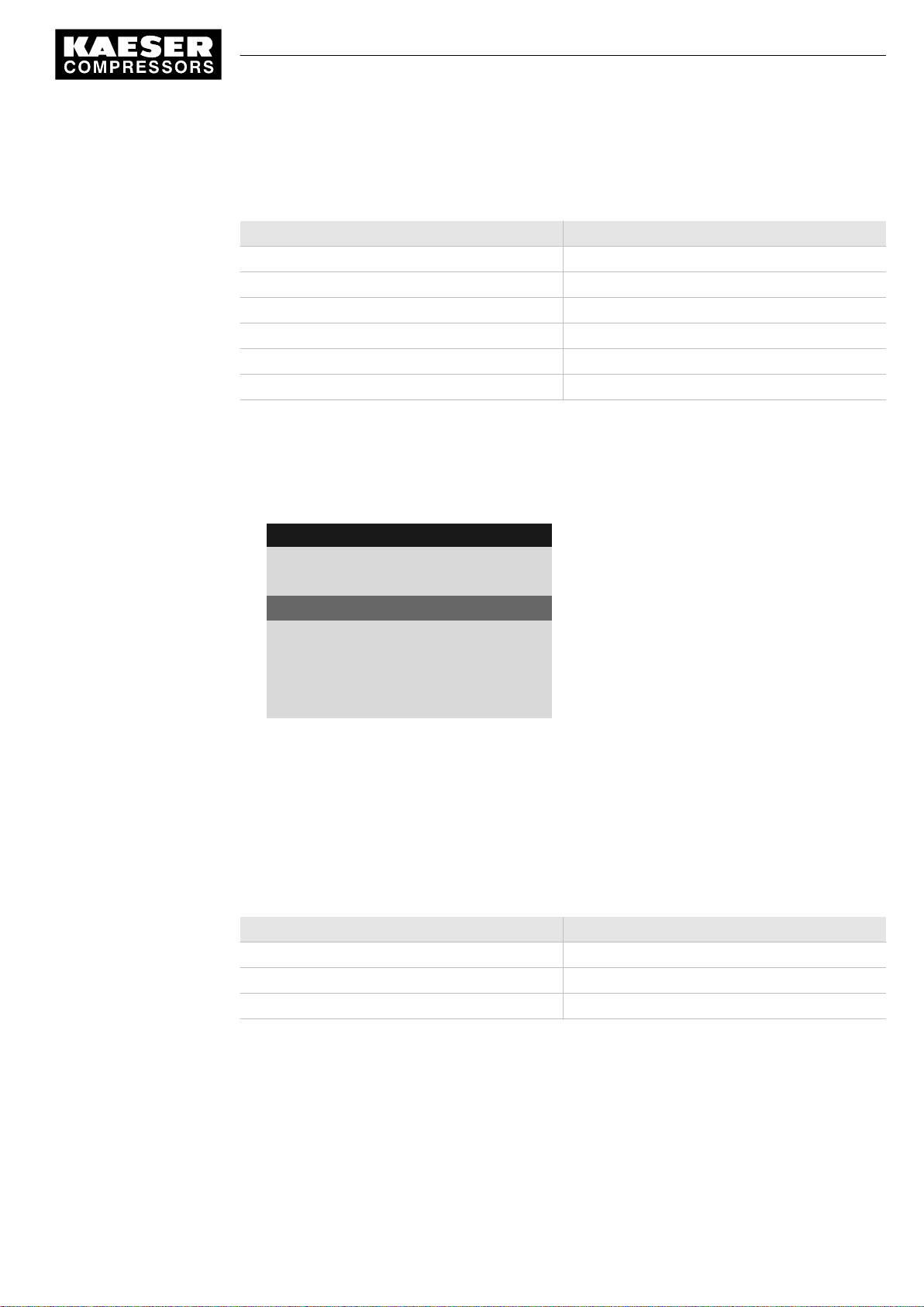
7 Initial Start-up
7.2 Configuring the controller
Setting the pressure display units
Select your preferred display of the pressure unit:
Format Example:
bar 5.5 bar
hPa 5523 hPa
MPa 0.55 MPa
psi 80 psi
at 5.6 at
"Hg 162.9 "Hg
Tab. 43 Units of pressure
Precondition Password level 2 is activated,
menu
< Configuration> General >
is selected (see 7.2.1).
1. Press the «DOWN» key repeatedly until
8 8 p s i 0 8 : 1 5 1 7 6 ° F
5.1 General
·········
Unit of pressure bar
Temperature unit °C
·········
2. Press «Enter» to switch into setting mode.
The
bar
parameter flashes.
3. Change the unit with the «DOWN» or «UP» keys.
4. Press «Enter» to save the setting.
5. Press «Escape» repeatedly to return to the main menu.
Setting the temperature display units
Select your preferred display of the temperature unit:
Format Example:
°C 46 °C
K 319 K
°F 114 °F
Unit of pressure
Menu
Current Unit of pressure
is displayed as active line.
Precondition Password level 2 is activated,
No.: 9_9450 00 USE
Tab. 44 Units of temperature
menu
< Configuration ➙ General >
Service Manual Controller
SIGMA CONTROL 2 SCREW FLUID 1.0.x.x
is selected (see 7.2.1).
37
Page 84

7 Initial Start-up
7.3 Pressure parameters of the machine
1. Press the «DOWN» key repeatedly until Temperature unit is displayed as active line.
8 8 p s i 0 8 : 1 5 1 7 6 ° F
5.1 General
·········
Unit of pressure bar
Temperature unit °C
·········
2. Press «Enter» to switch into setting mode.
The °C parameter flashes.
3. Change the unit with the «DOWN» or «UP» keys.
4. Press «Enter» to save the setting.
5. Press «Escape» repeatedly to return to the main menu.
Menu
Current Temperature unit
7.2.8 Setting and activating summer/winter time
The functions for summer/winter time are not yet implemented.
➤ Ignore any corresponding references to chapter 7.2.8 in this manual.
7.3 Pressure parameters of the machine
This chapter contains information on the display and configuration of all the machine pressure pa‐
rameters and is divided into the following sections:
■ 7.3.1: Displaying pressure parameters
■ 7.3.2: Configuring the pressure parameters
"Display:" means that the parameter will only be shown.
"Setting:" means that the parameter can also be changed.
Parameter Explanation
pRV Display:
Activating pressure of the safety relief valve on the oil separator tank
pE Pressure increase
Setting:
■ pE SP: Switching point pE; upper safety limit for machine maximum pressure;
in an external LOAD control, this value is used to switch the machine from
LOAD to IDLE.
■ pE SD: Switching differential pE
38
Service Manual Controller
SIGMA CONTROL 2 SCREW FLUID 1.0.x.x No.: 9_9450 00 USE
Page 85

7 Initial Start-up
7.3 Pressure parameters of the machine
Parameter Explanation
dpFC Limiting value for machines with frequency-controlled drive (SFC).
Setting:
■ dpFC Limit for minimum delivery. If this value is exceeded [Setpoint
pressure switching point + dpFC], the compressor switches from LOAD to
IDLE.
Nominal
pressure
Setpoint
pressure
System
pressure low
Display:
The compressor is designed for this pressure (maximum system pressure set-
point)
The Setpoint pressure can be regulated to two different values: pA and pB
Setting:
■ Switching point pA or control pressure pA in machines with frequency converter
(SFC)
■ Switching point pB or control pressure pB in machines with frequency converter
(SFC)
A warning message can be displayed when the limiting value System pressure low
is reached.
Setting:
■ BeSD: Switching differential System pressure low,
SP: Switching point System pressure low
■ Optional warning message: no message,
Warning message displayed or an additional output signal is sent, e.g., to a
control centre
Cut-in
pressure min
Tab. 45 Compressor pressure parameters
➤ Parameters correspond to the following specifications
Display:
For design reasons, pressure can only be built up above this value.
7.3.1 Displaying pressure parameters
Precondition Password level 2 is activated.
The
< Configuration ➙ Pressure control >
Opening the menu for pressure parameters
1. Press «DOWN» or «UP» repeatedly until
menu is selected.
Pressure settings
is displayed as active line.
No.: 9_9450 00 USE
Service Manual Controller
SIGMA CONTROL 2 SCREW FLUID 1.0.x.x
39
Page 86
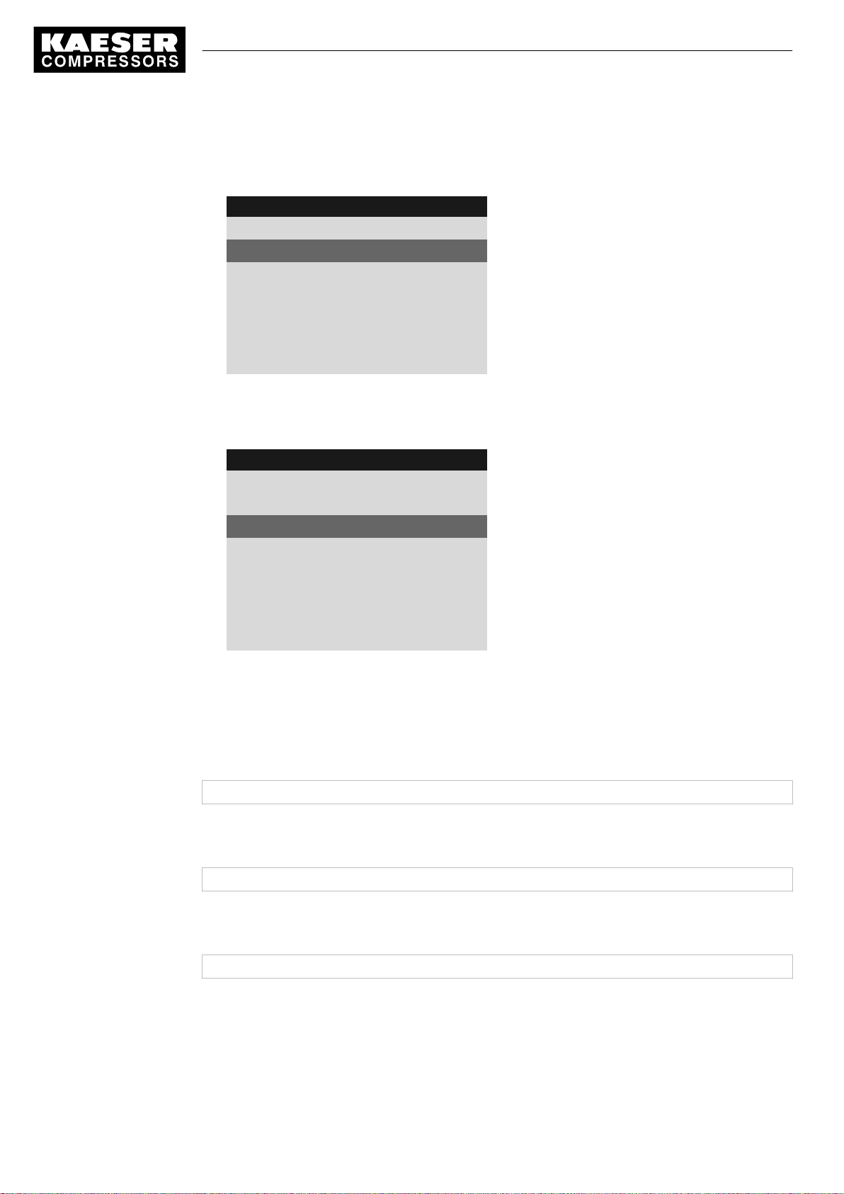
7 Initial Start-up
7.3 Pressure parameters of the machine
2. Press «Enter».
The system displays the pressure parameters.
8 8 p s i 0 8 : 1 5 1 7 6 ° F
5.2.2 Pressure settings
pA SP: 116 psi ¦ SD: - 7 psi
pB SP: 110 psi ¦ SD: - 6 psi
·········
System pressure low ☐
↓ < 73 psi ¦ SD: 7 psi
ta: 600 s ¦ DOR 1.04 ☐
Displaying compressor parameters
Menu
Active line
1. Press «DOWN» repeatedly until
Setpoint pressure
is displayed.
8 8 p s i 0 8 : 1 5 1 7 6 ° F
5.2.2 Pressure settings
·········
Setpoint pressure
pA SP: 116 psi ¦ SD: - 7 psi
Menu
Active line
current Setpoint pressure pA and switching differen‐
tial
pB SP: 110 psi ¦ SD: - 6 psi
current Setpoint pressure pB and switching differen‐
tial
·········
System pressure low ☐
2. Display further parameters with «UP» and «DOWN».
7.3.2 Configuring the pressure parameters for compressors
7.3.2.1 Adjusting system set-point pressure pA and pB
The pressure parameters can only be set within certain limits:
Rated machine pressure ≥ SP: pA /pB ≥ minimum cut-in pressure* + switching differential
Tab. 46 Setting limits for system set-point pressure (* Cut-in pressure min)
40
The machine switches to LOAD under the following condition:
System pressure ≤ SP: pA /pB - switching differential
Tab. 47 Pressure condition for LOAD
The machine switches to IDLE under the following condition:
System pressure = Setpoint pressure
Tab. 48 Pressure condition for IDLE
Precondition Password level 2 is activated.
1. Select
Service Manual Controller
SIGMA CONTROL 2 SCREW FLUID 1.0.x.x No.: 9_9450 00 USE
< Configuration ➙ Pressure control ➙ Pressure settings >
(see Section 7.3.1)
Page 87
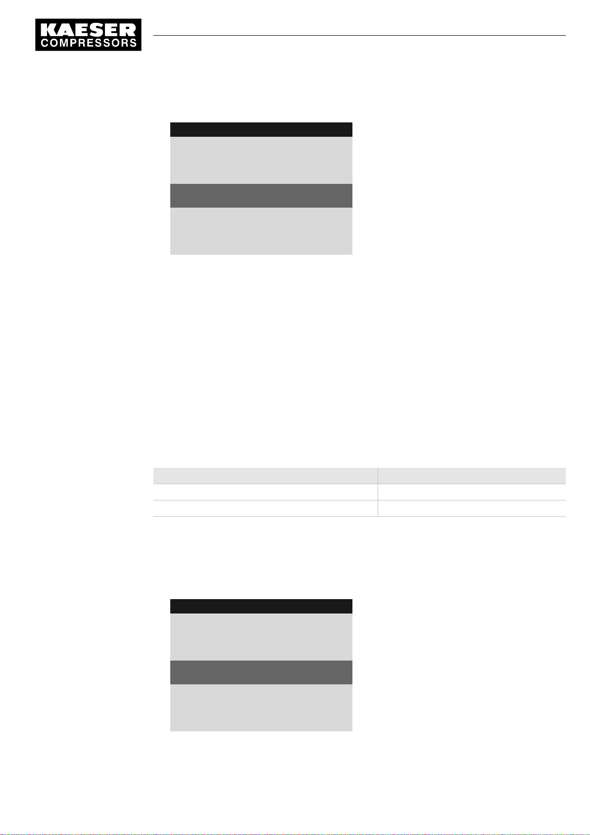
7 Initial Start-up
7.3 Pressure parameters of the machine
2. Press «UP» or «DOWN» repeatedly until the following is displayed as active line:
8 8 p s i 0 8 : 1 5 1 7 6 ° F
5.2.2 Pressure settings
·········
Setpoint pressure
pA SP: 116 psi ¦ SD: - 7 psi
pB SP: 110psi ¦ SD: - 6 psi
·········
System pressure low ☐
3. Press «Enter» to switch into setting mode.
The
116 psi
parameter flashes.
4. Use «UP» or «DOWN» to adjust Setpoint pressure pA.
5. Press «Enter» to accept the setting.
6. Adjust the switching differential in the same way.
7. Adjust the Setpoint pressure pB and the switching differential in the same way, if necessary.
8. Press «Escape» repeatedly to return to the main menu.
Menu
Active line with current value for Setpoint pressure
pA
Result The settings for Setpoint pressure pA and pB are adjusted.
7.3.2.2 Adjusting the value for "System pressure low"
If the system pressure falls to the "System pressure low" value, SIGMA CONTROL 2 will display a
warning message for the system pressure being too low.
The switching differential influences the pressure at which the message can be acknowledged or
the optionally activated output will again switch:
Message Output
73 psi Message coming active
80 psi Message going inactive
Tab. 49 Example: Activated output
Precondition Password level 2 is activated.
1. Select
< Configuration ➙ Pressure control ➙ Pressure settings >
2. Press the «DOWN» key repeatedly until the following is displayed as active line:
8 8 p s i 0 8 : 1 5 1 7 6 ° F
5.2.2 Pressure settings
·········
System pressure low ☐
↓ < 73 psi ¦ SD: 7 psi
ta: 600 s ¦ DOR 1.04 ☐
·········
Cut-in pressure min 73 psi
(see Section 7.3.1)
Menu
Current value System pressure low ¦ current switch‐
ing differential
No.: 9_9450 00 USE
Service Manual Controller
SIGMA CONTROL 2 SCREW FLUID 1.0.x.x
41
Page 88

7 Initial Start-up
7.3 Pressure parameters of the machine
3. Press «Enter» to switch into setting mode.
The
73 psi
parameter flashes.
4. Use «UP» or «DOWN» to adjust the setting.
5. Press «Enter» to accept the setting.
6. Adjust the switching differential if necessary in the same way.
7. Press «Escape» repeatedly to return to the main menu.
7.3.2.3 Adjusting pressure rise pE
The value for pressure rise pE serves as a safety limit value when the machine is externally con‐
trolled. When the system set pressure reaches the value pE (for example, when the external con‐
trol functions incorrectly) the machine switches to IDLE.
The warning message
Precondition Password level 2 is activated.
External load signal?
is triggered.
1. Select
2. Press the «DOWN» key repeatedly until the following is displayed as active line:
3. Press «Enter» to switch into setting mode.
4. Use «UP» or «DOWN» to adjust the setting.
5. Press «Enter» to accept the setting.
6. Adjust the switching differential if necessary in the same way.
7. Press «Escape» repeatedly to return to the main menu.
7.3.2.4 Adjusting pressure rise in frequency-controlled machines (SFC)
< Configuration ➙ Pressure control ➙ Pressure settings >
8 8 p s i 0 8 : 1 5 1 7 6 ° F
5.2.2 Pressure settings
pRV 232 psi
·········
Pressure rise
pE SP: 122 psi ¦ SD: - 7 psi
dpFC : 3 psi
·········
The
122 psi
parameter flashes.
Menu
Active line with current switching point Pressure rise
¦ current switching differential
(see Section 7.3.1)
42
The pressure rise value
This value can be between 3 psi and 6 psi. The factory setting is 3 psi.
The pressure rise is added to the set-point pressure. In this way, the set-point pressure can be
changed without having to adjust the parameter again.
Precondition Password level 2 is activated.
Service Manual Controller
SIGMA CONTROL 2 SCREW FLUID 1.0.x.x No.: 9_9450 00 USE
dpFC
is the limit from which the machine switches to IDLE.
Page 89
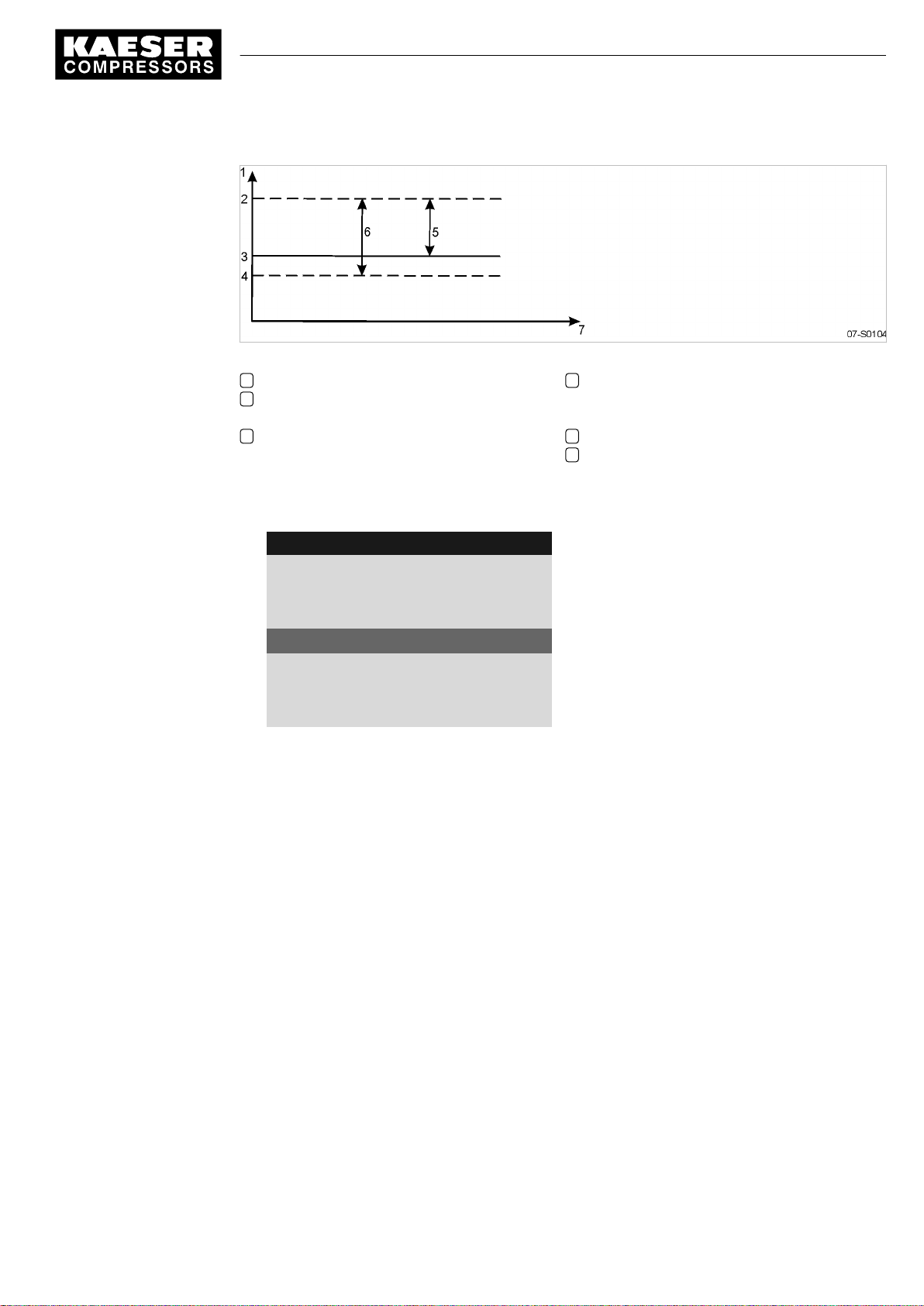
7 Initial Start-up
7.3 Pressure parameters of the machine
Fig. 6 Pressure rise in frequency-controlled machines
1 System pressure
2 IDLE switching point:
Setpoint pressure + dpFC
3 Setpoint pressure pA or pB
4 LOAD switching point:
(Setpoint pressure + dpFC) - switching dif‐
ferential
5 Pressure rise dpFC
6 System pressure band width
1. Select
< Configuration ➙ Pressure control ➙ Pressure settings >
2. Press «DOWN» repeatedly until the following is displayed:
8 8 p s i 0 8 : 1 5 1 7 6 ° F
5.2.2 Pressure settings
Pressure rise
pE SP: 122 psi ¦ SD: - 7 psi
dpFC : 3 psi
·········
Nominal pressure 116 psi
·········
3. Press «Enter» to switch into setting mode.
4. Use «UP» or «DOWN» to adjust the setting.
5. Press «Enter» to accept the setting.
6. Press «Escape» repeatedly to return to the main menu.
7.3.3 Activating/deactivating the «IDLE» key
In order to prevent unauthorized users from switching the machine to IDLE, you can deactivate the
«IDLE» key on the operating panel.
(see Section 7.3.1)
Menu
Pressure increase
Active line with pressure increase value dpFC
Precondition Password level 2 is activated,
No.: 9_9450 00 USE
The
< Configuration ➙ Pressure control ➙ Load control >
menu is selected (see Section 7.2.1).
1. Press «UP» or «DOWN» repeatedly until «IDLE» key is displayed as active line.
Service Manual Controller
SIGMA CONTROL 2 SCREW FLUID 1.0.x.x
43
Page 90
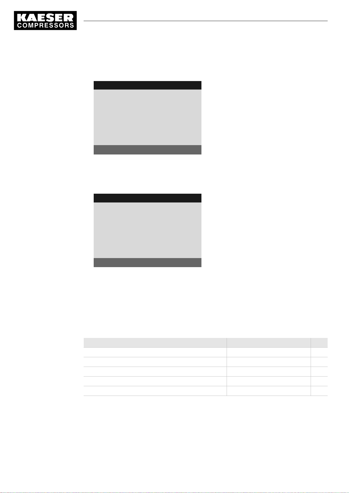
7 Initial Start-up
7.4 Configuring machine start and stop
2. Press «Enter» to switch into setting mode.
The check box for «IDLE» key will flash.
8 8 p s i 0 8 : 1 5 1 7 6 ° F
5.2.3 Load control
pA/pB DO DOR1.04 ☐
·········
load RC Tue1.13 ok ☑
loc.-loadRC Tue1.09 ☑
·········
Key idle : ☑
3. Press «UP».
The deactivated check box is displayed.
4. Press «Enter» to save the setting.
The «IDLE» key is de-activated.
Menu
Active line with check box
8 8 p s i 0 8 : 1 5 1 7 6 ° F
5.2.3 Load control
pA/pB DO DOR1.04 ☐
·········
load RC Tue1.13 ok ☑
loc.-loadRC Tue1.09 ☑
·········
Key idle : ☐
5. Press «Escape» repeatedly to return to the main menu.
Result Thus, it is ensured that unauthorized users can press the «IDLE» key without the machine switch‐
ing to IDLE.
Menu
Active line with deactivated check box
7.4 Configuring machine start and stop
➤ In addition to manually starting the machine locally, you have the following alternatives:
Function State on delivery/setting See
Automatic start/stop in programmed clock mode No clock (time) program entered 7.4.1
Holidays Not set 7.4.2
Remote start, e.g. from a control center Deactivated 7.4.3
IDLE (venting) Activated 7.4.4
Automatic restart after power failure (after delay period). Activated 7.4.5
44
Tab. 50 Settings for machine start and stop.
7.4.1 Automatic start/stop in programmed clock mode
Overview
■ If not activated, enter password for level 2.
Service Manual Controller
SIGMA CONTROL 2 SCREW FLUID 1.0.x.x No.: 9_9450 00 USE
Page 91
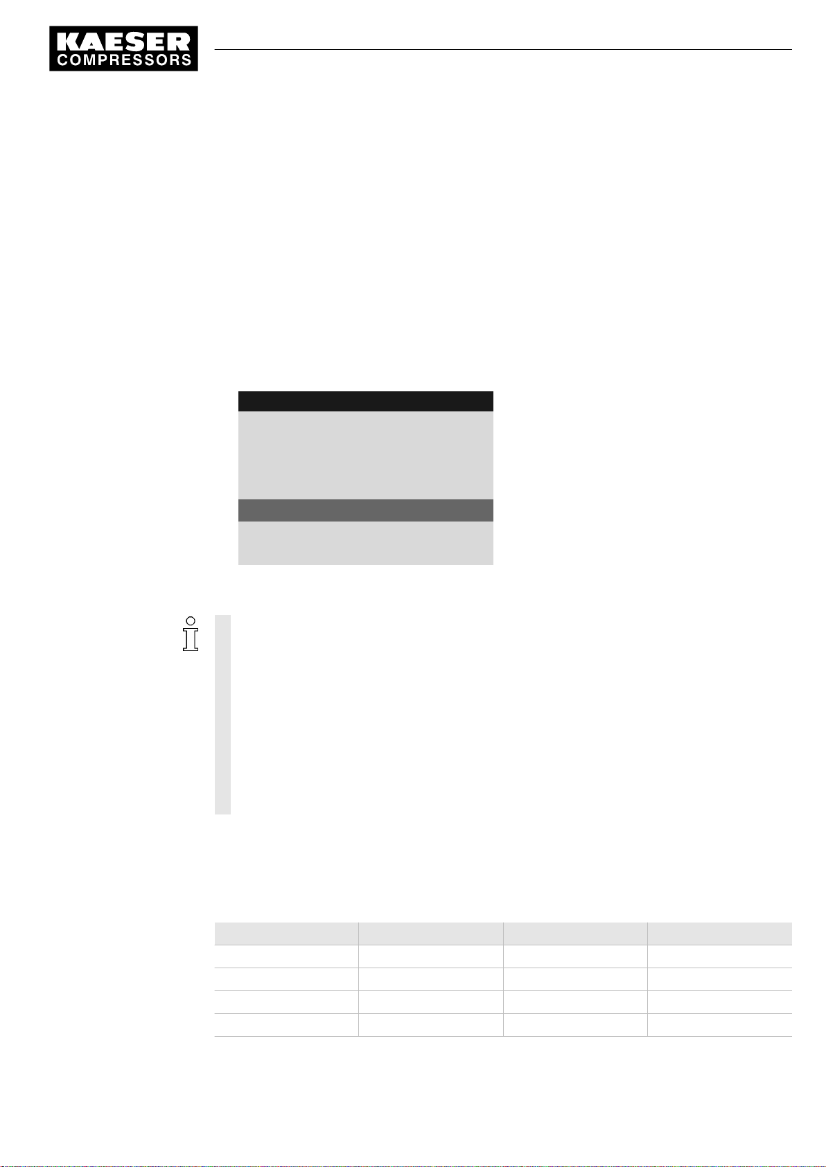
7 Initial Start-up
7.4 Configuring machine start and stop
■ Select
< Compressor clock >
■ set/adjust the time program.
■ Activate the «clock» key.
7.4.1.1 Selecting the Compressor clock menu
Precondition Password level 2 is activated.
The display shows the operating mode.
1. Press «Enter».
The main menu is displayed.
2. Select
< Compressor clock >
The display for setting the Compressor clock timing program appears.
8 8 p s i 0 8 : 1 5 1 7 6 ° F
6 Compressor clock
Key clock : ☐
Reset: ☐
·········
01 n.a. 00:00 off
02 n.a. 00:00 off
03 n.a. 00:00 off
.
.
Menu
The Compressor clock key is activated
All current switching points are reset
Active line
7.4.1.2 Setting the clock program (example)
When setting a clock program for the first time, note the switching times on a sheet of paper
first.
In addition to individual week days, the controller has the following cycles:
■ Mon-Thu
■ Mon-Fri
■ Mon-Sat
■ Mon-Sun
■ Sat-Thu
You can also program an OFF time (Shutdown periods) (see Section 7.4.2).
Example:
■ Machine ON: Weekdays 6:30 – 17:00, Fridays 6:30 – 15:00.
■ Machine OFF: Sat – Sun and during midday break from 12:00 – 13:00.
The following switching points result:
No. Day Time Function
1 Mon-Fri 06:30 ON
2 Mon-Fri 12:00 OFF
3 Mon-Fri 13:00 ON
4 Mon-Thu 17:00 OFF
No.: 9_9450 00 USE
Service Manual Controller
SIGMA CONTROL 2 SCREW FLUID 1.0.x.x
45
Page 92

7 Initial Start-up
7.4 Configuring machine start and stop
No. Day Time Function
5 Fri 15:00 OFF
Tab. 51 Example of a machine ON/OFF clock program
Precondition Password level 2 is activated,
the «clock» key is activated,
the "clock" menu is selected.
1. Press «DOWN» repeatedly until the 01 switching point is displayed as active line.
8 8 p s i 0 8 : 1 5 1 7 6 ° F
6 Compressor clock
·········
01 n.a. 00:00 off
02 n.a. 00:00 off
03 n.a. 00:00 off
04 n.a. 00:00 off
05 n.a. 00:00 off
Menu
Active line with 01 switching point
Switching point 02
Switching point 03
Switching point 04
Switching point 05
2. Press «Enter» to switch into setting mode.
The
n.a.
column flashes in the active line.
3. Use «UP» to specify the settings for the weekdays.
4. Press «Enter» to accept the setting.
5. Press the «Right» key once.
6. Press «Enter» to switch into setting mode.
Time column, hours display,
00 : 00
flashes in the active line.
7. Use «UP» to specify the settings for the hours.
8. Press the «Right» key once.
9. Time column, minutes display, 00
: 00
flashes in the active line.
10. Use «UP» to specify the settings for the minutes.
11. Press «Enter» to accept the settings.
The display stops flashing and the time (hours/minutes) is set.
8 8 p s i 0 8 : 1 5 1 7 6 ° F
6 Compressor clock
·········
01 Mon-Fri 06:30 on
02 Mon-Fri 12:00 off
03 Mon-Fri 13:00 on
04 Mon-Thu 17:00 off
05 Fri 15:00 off
Menu
Switching point 01 is set
Switching point 02 is set
Switching point 03 is set
Switching point 04 is set
Switching point 05 is set
46
12. Press the «Right» key once.
The
Action off / on
column flashes.
13. Press «Enter» to switch into setting mode.
14. Use «UP» to specify the settings for the Compressor ON action.
Service Manual Controller
SIGMA CONTROL 2 SCREW FLUID 1.0.x.x No.: 9_9450 00 USE
Page 93

7 Initial Start-up
7.4 Configuring machine start and stop
15. Press «Enter» to accept the setting.
The Compressor ON action is set for the first switching point.
16. Specify further switching points in the same manner.
Result Weekdays, time and the Compressor ON / Compressor OFF actions are set for all switching
points.
7.4.1.3 Activating the«compressor clock» key
1. Press the «UP» repeatedly until
2. Press «Enter» to switch into setting mode.
The check box flashes in the active line.
8 8 p s i 0 8 : 1 5 1 7 6 ° F
6 Compressor clock
Key clock : ☑
Reset: ☐
·········
01 Mon-Fri 06:30 on
02 Mon-Fri 12:00 off
03 Mon-Fri 13:00 on
3. Activate the check box with «UP» and press «Enter».
4. Press «Escape» repeatedly to return to the main menu.
The «clock» key is activated and can be used.
5. Press «clock» to enable the operation with a timing program.
7.4.2 Setting up the holiday period
The functions for company shutdown are not yet implemented.
➤ Ignore any corresponding references to chapter 7.4.2 in this manual.
Key clock
is displayed as active line.
Menu
Active line with deactivated check box
Switching point 01
Switching point 02
Switching point 03
No.: 9_9450 00 USE
7.4.3 Starting the machine remotely from a control center (remote ON/OFF or re‐
mote control function)
If the machine is to be started and stopped from a remote control center then the following settings
have to be made:
Overview
■ Make the electrical connection (a spare input for the remote contact is shown in the electrical
wiring diagram for the machine, preferably DI 1.12).
■ Switch machine start to remote mode.
■ Activate the «remote control» key.
■ If required, activate the «clock» key and configure the clock program (see Section 7.4.1.2)
■ If required, assign the remote contact to another input.
■ Press the «remote control» key.
Service Manual Controller
SIGMA CONTROL 2 SCREW FLUID 1.0.x.x
47
Page 94

7 Initial Start-up
7.4 Configuring machine start and stop
7.4.3.1 Switching the machine start to Remote mode
Two methods are available to start the machine remotely from a control center:
■ Method A: Starting the machine with the input signal from the remote control center.
■ Method B: Starting the machine from the remote control center in addition to a configured ON/
OFF clock program.
The machine can be started from the remote control center even though the clock is activated
and the actual program sequence is OFF at this point in time.
Precondition The electrical connection has been made.
Password level 2 is activated.
The display shows the operating mode.
1. Press «Enter».
The main menu is displayed.
2. Select the
3. Press the «UP» repeatedly until
4. Press «Enter» to switch into setting mode.
Key
< Configuration ➙ Compressor start ➙ Compressor ON >
Remote mode
flashes.
menu.
is displayed as active line.
8 8 p s i 0 8 : 1 5 1 7 6 ° F
5.4.1 Compressor ON
local mode : Key
Remote mode : Key
·········
current Key
·········
RC DI 1.12 ok ☑
5. Press «DOWN» repeatedly until
Key+RC
6. Press «Enter» to accept the setting.
8 8 p s i 0 8 : 1 5 1 7 6 ° F
5.4.1 Compressor ON
local mode : Key
Remote mode : Key+RC
·········
current Key
·········
RC DI 1.12 ok ☑
Menu
Active line
is displayed.
Menu
Active line with Key+RC
48
Result The machine start is set to Remote mode with Key+RC.
7.4.3.2 Activating/deactivating the «remote control» key
Precondition The electrical connection has been made.
Password level 2 is activated.
The display shows the operating mode.
Service Manual Controller
SIGMA CONTROL 2 SCREW FLUID 1.0.x.x No.: 9_9450 00 USE
Page 95
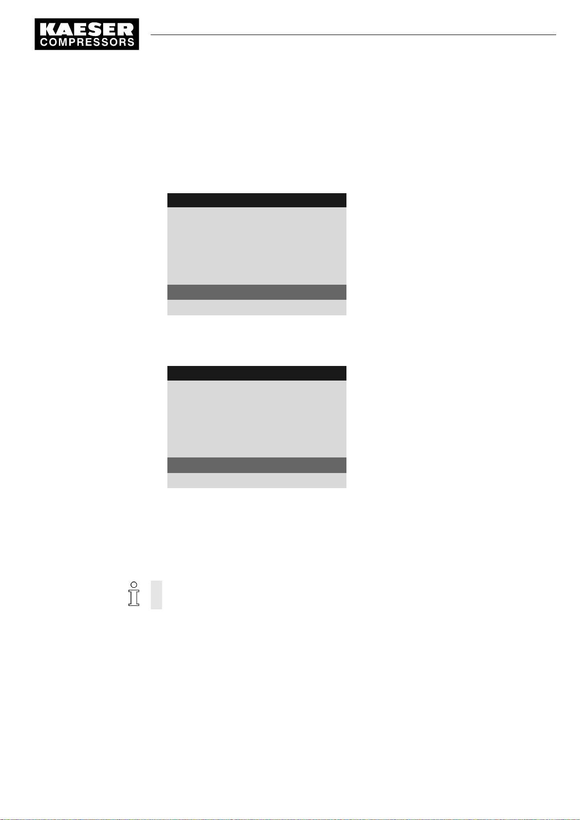
7 Initial Start-up
7.4 Configuring machine start and stop
1. Press «Enter».
The main menu is displayed.
2. Select the
3. Press «DOWN» repeatedly until
4. Press «Enter» to switch into setting mode.
The check box for Key remote will flash.
8 8 p s i 0 8 : 1 5 1 7 6 ° F
< Configuration ➙ Compressor start ➙ Compressor ON >
Key remote
5.4.1 Compressor ON
·········
current Key
·········
RC DI 1.12 ok ☑
Key remote : ☐
Key clock : ☐
menu.
is displayed as active line.
Menu
Active line with check box
5. Press «UP».
The activated check box is displayed.
6. Confirm the setting with «Enter».
8 8 p s i 0 8 : 1 5 1 7 6 ° F
5.4.1 Compressor ON
·········
current Key
·········
RC DI 1.12 ok ☑
Key remote : ☑
Key clock : ☐
7. Press «Escape» repeatedly to return to the main menu.
The «remote control» key is activated and can be used.
8. If method B with the clock program is selected, the «clock» key must be activated in the same
manner.
7.4.3.3 Assigning another input
Inputs already assigned cannot be further assigned.
Menu
Active line with deactivated check box
The clock key is not activated.
No.: 9_9450 00 USE
Service Manual Controller
SIGMA CONTROL 2 SCREW FLUID 1.0.x.x
49
Page 96

7 Initial Start-up
7.4 Configuring machine start and stop
1. Press the «DOWN» key repeatedly until the following is displayed as active line:
8 8 p s i 0 8 : 1 5 1 7 6 ° F
5.4.1 Compressor ON
·········
current Key
·········
RC DI 1.12 ok ☑
Key remote : ☑
Key clock : ☐
2. Press «Enter».
An inverse cursor appears.
3. Use the «UP» or «DOWN» keys to select another input and confirm with «Enter».
The input has now been assigned.
4. Press the «Remote» key to enable the machine to be started from the remote control center.
Menu
Remote contact DI 1.12 (default)
Active line
If an input is rejected it means it is already assigned.
➤ Select a different input.
7.4.4 Activating/deactivating the idle phase (Venting period function)
After receiving the OFF signal from the remote control center, an additional idling (Venting period
function) phase can be activated before the machine is stopped completely. The duration of the
idling phase can be timed and/or regulated by internal pressure.
Precondition Password level 2 is activated.
The display shows the operating mode.
1. Press «Enter».
The main menu is displayed.
2. Select the
The
3. Press «Enter» to switch into setting mode.
The check box for the "Venting period" function will flash.
8 8 p s i 0 8 : 1 5 1 7 6 ° F
< Configuration ➙ Compressor start ➙ Compressor OFF >
"Venting period"
5.4.2 Compressor OFF
Venting period : ☐
function is displayed in the active line.
Menu
Current setting " Venting period " is deactivated
menu.
50
4. Press «UP».
The check box for the "Venting period" function is activated.
Service Manual Controller
SIGMA CONTROL 2 SCREW FLUID 1.0.x.x No.: 9_9450 00 USE
Page 97

7 Initial Start-up
7.4 Configuring machine start and stop
5. Press «Enter» to save the setting.
The function can be deactivated in the same manner.
Result The "Venting period" function is activated.
7.4.5 Activating/deactivating and adjusting the "automatic restart after a power fail‐
ure" function
'Autostart' is activated as standard.
To avoid overloading the main power supply through several machines starting simultaneously a
delay period determining the restart of each machine can be entered.
Overview
■ If not activated, enter password for level 2
■ Select the
■ Activate/deactivate the restart function
or
set the restart delay.
< Configuration ➙ Compressor start >
menu.
Precondition Password level 2 is activated.
The
< Configuration ➙ Compressor start >
1. Press «Enter».
The
Compressor start
8 8 p s i 0 8 : 1 5 1 7 6 ° F
5.4 Compressor start
▶1 Compressor ON
▶2 Compressor OFF
·········
Autostart : ☑
Target 10 s ¦ Actual 0 s
·········
Deactivating/activating automatic restart
1. Press «DOWN» repeatedly until Autostart is displayed as active line.
8 8 p s i 0 8 : 1 5 1 7 6 ° F
5.4 Compressor start
▶1 Compressor ON
▶2 Compressor OFF
·········
Autostart : ☐
Target 10 s ¦ Actual 0 s
·········
menu is displayed.
menu option is selected.
Menu
Active line
Automatic restart activated.
Menu
Automatic restart is deactivated
Set/expiring delay period
No.: 9_9450 00 USE
Service Manual Controller
SIGMA CONTROL 2 SCREW FLUID 1.0.x.x
51
Page 98
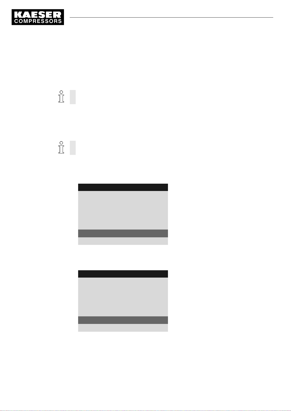
7 Initial Start-up
7.4 Configuring machine start and stop
2. Press «Enter» to switch into setting mode.
The check box for the "Autostart" function will flash.
3. Press «UP».
The check box for the "Autostart" function is activated.
4. Press «Enter» to accept the setting.
Activate the “Autostart” function in the same manner.
5. Press «Escape» repeatedly to return to the main menu.
Result Automatic restart after a power failure is now deactivated.
Setting up the automatic restart delay period
If you operate several machines, it is better to start them in sequence.
Time for restart: Use the set times (IDLE to LOAD) of the other machines as base.
Precondition Password level 2 is activated.
The
< Compressor start >
menu is selected.
1. Press «DOWN» repeatedly until the delay time for the restart is displayed as active line.
8 8 p s i 0 8 : 1 5 1 7 6 ° F
5.4 Compressor start
▶1 Compressor ON
▶2 Compressor OFF
·········
Autostart : ☑
Target 10 s ¦ Actual 0 s
·········
2. Press «Enter» to switch into setting mode.
Target
flashes.
3. Change the time using the «DOWN» or «UP» keys.
8 8 p s i 0 8 : 1 5 1 7 6 ° F
5.4 Compressor start
▶1 Compressor ON
▶2 Compressor OFF
·········
Autostart : ☑
Target 12 s ¦ Actual 0 s
·········
Menu
automatic restart is activated
Set/expiring delay period
Menu
Active line
52
4. Press «Enter» to accept the setting.
5. Press «Escape» repeatedly to return to the main menu.
Result You have adjusted the delay tome for the restart after a mains failure from 10 s to 12 s.
Service Manual Controller
SIGMA CONTROL 2 SCREW FLUID 1.0.x.x No.: 9_9450 00 USE
Page 99
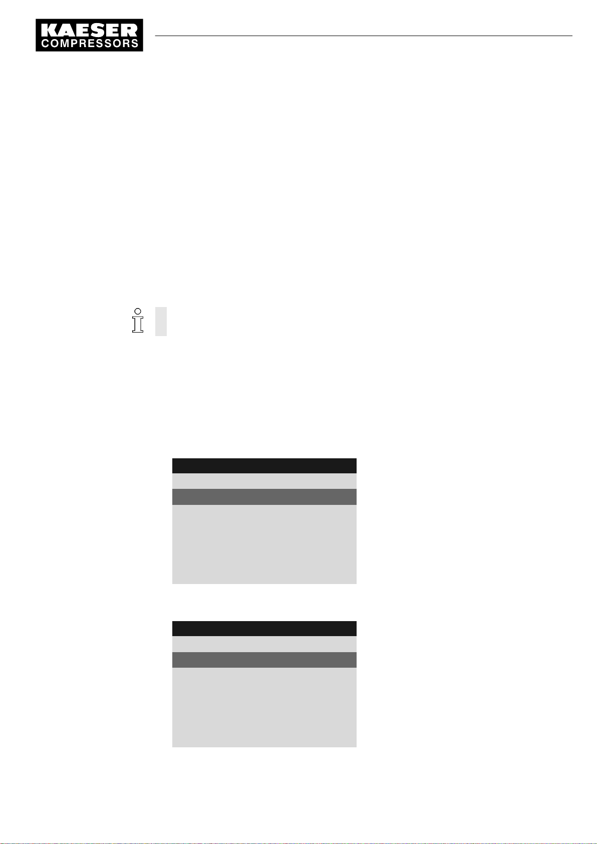
7 Initial Start-up
7.5 Activating and setting up the control modes
7.5 Activating and setting up the control modes
The controller is provided with various control modes that can bring about different capacity utiliza‐
tion depending on machine application. Chapter 4.6 provides a comprehensive description of all
control modes.
7.5.1 Selecting a control mode
The following control modes are possible:
■ DUAL
■ QUADRO
■ VARIO
■ DYNAMIC
■ CONTINUOUS
The standard setting of Control Mode depends on the machine type.
Precondition Password level 2 is activated.
The display shows the operating mode.
1. Press «Enter».
The main menu is displayed.
2. Select the
3. Press «UP» repeatedly until
The Control Mode setting is shown in the active line.
8 8 p s i 0 8 : 1 5 1 7 6 ° F
4. Press «Enter» to switch into setting mode.
DUAL
8 8 p s i 0 8 : 1 5 1 7 6 ° F
< Configuration ➙ Control Mode >
5.3 Control Mode
local mode : DUAL
·········
current DUAL
·········
▶1 Venting period
·········
flashes.
5.3 Control Mode
local mode : QUADRO
·········
current QUADRO
·········
▶1 Venting period
·········
local mode
menu.
is displayed as active line.
Menu
Active line
Current Control Mode
Menu Venting period
Menu
Active line
Changed current Control Mode
Menu Venting period
No.: 9_9450 00 USE
5. Use «UP» to adjust Control Mode to the QUADRO setting.
Service Manual Controller
SIGMA CONTROL 2 SCREW FLUID 1.0.x.x
53
Page 100

7 Initial Start-up
7.5 Activating and setting up the control modes
6. Press «Enter» to accept the setting.
The new Control Mode
7. Press «Escape» repeatedly to return to the main menu.
7.5.2 Adjusting Idle period of Control Mode DUAL
When the Idle period period has elapsed, the machine comes to a STANDSTILL.
The shorter the period, the more often the machine will switch from IDLE to STANDSTILL.
SIGMA CONTROL 2 will take into account the maximum motor switching capacity.
Depending on the machine type, the machine may not fall below a minimum Idle period or standstill
time.
Precondition Password level 2 is activated.
DUAL control mode is selected.
The display shows the operating mode.
1. Press «Enter».
The main menu is displayed.
2. Select the
The Idle period setting is shown in the active line.
< Configuration ➙ Control Mode ➙ DUAL >
QUADRO
is shown in the
current
line.
menu. (see section 7.5.1)
8 8 p s i 0 8 : 1 5 1 7 6 ° F
5.3.3 DUAL
Idle period
Target 240 s ¦ Actual 0 s
3. Press «Enter» to switch into setting mode.
The current
8 8 p s i 0 8 : 1 5 1 7 6 ° F
5.3.3 DUAL
Idle period
Target 300 s ¦ Actual 0 s
Idle period 240 s
flashes.
Menu
Active line
Menu
Active line with changed Idle period , (example: 300
seconds)
54
4. Use «UP» to change to the desired Idle period.
5. Press «Enter» to accept the setting.
6. Press «Escape» repeatedly to return to the main menu.
Service Manual Controller
SIGMA CONTROL 2 SCREW FLUID 1.0.x.x No.: 9_9450 00 USE
 Loading...