

Page 1
User Manual
Controller
SIGMA CONTROL 2 SCREW FLUID ≥4.0.X
No.: 9_9450 07 USE
Manufacturer:
KAESER KOMPRESSOREN SE
96410 Coburg • PO Box 2143 • GERMANY • Tel. +49-(0)9561-6400 • Fax +49-(0)9561-640130
http://www.kaeser.com
Page 2

/KKW/SSC 2.08 en Z1 IBA-SIGMA CONTROL FLUID
/KKW/SSC 2.08 Z1
20170413 074810
Page 3

Contents
1 SIGMA CONTROL 2 Quick installation guide
1.1 Operating elements .......................................................................................................... 1
1.2 Display elements .............................................................................................................. 2
1.3 Main menu ....................................................................................................................... 2
1.4 Functions – Overview ....................................................................................................... 3
2 Regarding this Document
2.1 Using this document ......................................................................................................... 5
2.2 Copyright .......................................................................................................................... 5
2.2.1 Software .............................................................................................................. 5
2.3 Approvals ......................................................................................................................... 6
2.4 Updating the user manual ................................................................................................ 6
2.5 Symbols and labels .......................................................................................................... 6
2.5.1 Warnings ............................................................................................................. 7
2.5.2 Potential damage warnings ................................................................................ 7
2.5.3 Other alerts and their symbols ............................................................................ 8
3 Technical Data
3.1 SIGMA CONTROL 2 Controller ....................................................................................... 9
3.1.1 Versions and options .......................................................................................... 9
3.1.2 User interface with display, CPU and interfaces ................................................. 9
3.1.3 Inputs and outputs with MCSIO .......................................................................... 12
3.1.4 Input/output modules .......................................................................................... 12
3.1.5 Sensors ............................................................................................................... 14
4 Safety and Responsibility
4.1 Basic instructions ............................................................................................................. 16
4.2 Specified use .................................................................................................................... 16
4.3 Improper use .................................................................................................................... 16
5 Design and Function
5.1 The controller ................................................................................................................... 17
5.2 Operating panel ................................................................................................................ 19
5.2.1 Indicating and operating elements ...................................................................... 19
5.2.2 Display elements ................................................................................................ 20
5.2.3 RFID reader ........................................................................................................ 21
5.3 Display ............................................................................................................................ 21
5.3.1 Operating mode .................................................................................................. 22
5.3.2 Main menu .......................................................................................................... 23
5.3.3 Setting parameters ............................................................................................. 23
5.3.4 Activating keys with check boxes ....................................................................... 24
5.4 Access rights .................................................................................................................... 24
5.5 KAESER CONNECT ........................................................................................................ 25
5.6 Menus – overview ............................................................................................................ 26
5.6.1 Operating mode .................................................................................................. 26
5.6.2 Menu structure .................................................................................................... 27
5.7 Operating modes and control modes ............................................................................... 42
5.7.1 Operating modes ................................................................................................ 42
5.7.2 Control modes .................................................................................................... 43
5.7.3 Frequency-controlled drive (SFC) ....................................................................... 44
5.7.4 MODULATING control ........................................................................................ 45
No.: 9_9450 07 USE
6 Installation and Operating Conditions
6.1 Maintaining ambient conditions ........................................................................................ 46
6.2 Installation conditions ....................................................................................................... 46
User Manual Controller
SIGMA CONTROL 2 SCREW FLUID ≥4.0.X
i
Page 4

Contents
7 Installation
7.1 Reporting Transport Damage ........................................................................................... 47
7.2 Machine identification ....................................................................................................... 47
8 Initial Start-up
8.1 Outline .............................................................................................................................. 48
8.2 Configuring the controller ................................................................................................. 48
8.2.1 Selecting menu options ...................................................................................... 49
8.2.2 Setting the language ........................................................................................... 50
8.2.3 Noting the number of the KAESER Equipment Card ......................................... 51
8.2.4 User log-in with KAESER Equipment Card ........................................................ 52
8.2.5 Generating a password ....................................................................................... 53
8.2.6 Manual user log-in .............................................................................................. 54
8.2.7 Checking and setting time and date ................................................................... 55
8.2.8 Set the time zone ................................................................................................ 57
8.2.9 Setting display formats ....................................................................................... 57
8.2.10 Setting the display illumination ........................................................................... 60
8.2.11 Setting the contrast and the brightness .............................................................. 61
8.2.12 Activating the remote control .............................................................................. 61
8.2.13 IP configuration .................................................................................................. 62
8.2.14 Setting the e-mail function ................................................................................. 63
8.2.15 Configuring the time server ................................................................................ 65
8.3 Using KAESER CONNECT .............................................................................................. 66
8.3.1 Open KAESER CONNECT ................................................................................. 67
8.3.2 System status menu ........................................................................................... 68
8.3.3 Graphs menu ...................................................................................................... 69
8.3.4 Messages menu ................................................................................................. 71
8.3.5 I/O display menu ................................................................................................. 72
8.3.6 User management menu .................................................................................... 73
8.3.7 Settings ............................................................................................................... 76
8.3.8 Backup menu ...................................................................................................... 77
8.3.9 Closing KAESER CONNECT ............................................................................. 77
8.4 Adjusting the pressure parameters of the machine ......................................................... 78
8.4.1 Displaying pressure parameters ......................................................................... 79
8.4.2 Configuring the pressure parameters ................................................................. 79
8.4.3 Activating/deactivating the «LOAD/IDLE» key .................................................... 82
8.5 Configuring machine start and stop ................................................................................. 83
8.5.1 Automatic start/stop in timer mode .................................................................... 83
8.5.2 Setting up the holiday period .............................................................................. 87
8.5.3 Starting the machine remotely (Remote ON/OFF) ............................................. 88
8.5.4 Activating the remote control ............................................................................. 90
8.5.5 Activating/deactivating the idle period "Venting period" function ....................... 91
8.5.6 Activating/deactivating and adjusting the "Autostart" function ............................ 91
8.6 Activating and adjusting the control modes ...................................................................... 94
8.6.1 Selecting a control mode .................................................................................... 94
8.6.2 Adjusting the idle time of DUAL control mode .................................................... 95
8.6.3 Adjusting the minimum running and unloaded period in QUADRO control
mode ...................................................................................................................
8.7 Electronic Thermal Management .................................................................................... 97
8.7.1 Activating the heat recovery for machine type 2 ................................................. 97
8.7.2 Activating the heat recovery for machine type 3 ................................................. 99
8.7.3 Deactivating heat recovery ................................................................................. 100
8.8 Refrigerated dryer ........................................................................................................... 101
8.8.1 Setting the operating mode ................................................................................. 101
8.8.2 Output messages ................................................................................................ 102
96
User Manual Controller
ii
SIGMA CONTROL 2 SCREW FLUID ≥4.0.X No.: 9_9450 07 USE
Page 5

Contents
8.8.3 Fault in the refrigerated dryer – compressed air quality has priority ................... 103
8.8.4 Fault in the refrigerated dryer – compressed air quantity has priority ................. 104
8.9 Configuring the machine for local mode .......................................................................... 105
8.9.1 Load control menu .............................................................................................. 105
8.9.2 Configuring the system setpoint pressure changeover using the clock .............. 106
8.9.3 Configuring the system setpoint pressure changeover using the timer .............. 109
8.10 Configuring the machine for master control ..................................................................... 111
8.10.1 List of the different master controllers ................................................................. 111
8.10.2 SAM 4.0 mode ................................................................................................... 111
8.10.3 Configuring PROFIBUS mode (SIGMA AIR MANAGER) ................................... 114
8.10.4 Configuring the master control of two machines in master/slave operation ...... 122
8.10.5 Configuring master control using the LOAD remote contact (e.g.,
SIGMA AIR MANAGER BASIC) ........................................................................
8.10.6 Configuring the master control with local/LOAD remote contact ....................... 130
8.10.7 Setting the setpoint pressure pre-selection via remote contact ......................... 133
8.10.8 Configuring master control of compressors regulated by pressure switch ........ 134
8.10.9 Examples of time settings for equal overall load ............................................... 140
8.11 Configuring input and output signals ................................................................................ 141
8.11.1 Outputting important operational states of the machine ..................................... 141
8.11.2 Output input signals on the display ..................................................................... 143
8.11.3 Output measured values on the display ............................................................. 147
8.12 Activating remote acknowledgement .............................................................................. 152
8.12.1 Setting the remote acknowledgement function ................................................... 153
8.12.2 Activating the remote control .............................................................................. 153
8.12.3 Assigning an input .............................................................................................. 154
8.13 Linking to an external pressure transducer ..................................................................... 155
8.13.1 Pressure control menu ........................................................................................ 155
8.13.2 Assigning an input to an external pressure transducer ...................................... 155
8.14 Commissioning the machine ........................................................................................... 156
128
9 Operation
9.1 Switching on and off ......................................................................................................... 158
9.1.1 Switching on ....................................................................................................... 158
9.1.2 Switching off ....................................................................................................... 159
9.2 Switching off in an emergency and switching on again .................................................... 159
9.3 Acknowledging alarm and warning messages ................................................................. 160
9.4 Displaying messages ...................................................................................................... 161
9.4.1 Selecting the status menu .................................................................................. 162
9.5 Displaying the current operating mode ........................................................................... 163
9.6 Adjusting the working pressure ........................................................................................ 164
9.7 Displaying analog data .................................................................................................... 164
9.8 Displaying operating data ................................................................................................ 165
9.8.1 Checking the operating hours ............................................................................. 166
9.8.2 Checking the switching cycles ............................................................................ 167
9.9 Displaying the frequency converter settings ................................................................... 168
9.10 Setting the maintenance interval ..................................................................................... 168
9.11 Checking the safety relief valve ...................................................................................... 170
9.12 Checking the temperature sensor and overheating shutdown function ........................... 172
9.13 Save data ........................................................................................................................ 174
10 Fault Recognition and Rectification
10.1 Basic instructions ............................................................................................................. 175
10.2 Interpreting alarm messages ............................................................................................ 175
10.3 Interpreting warning messages ........................................................................................ 184
10.4 Interpreting operation messages ...................................................................................... 197
No.: 9_9450 07 USE
User Manual Controller
SIGMA CONTROL 2 SCREW FLUID ≥4.0.X
iii
Page 6

Contents
10.5 Interpreting diagnostic messages .................................................................................... 201
10.6 Interpreting system messages ......................................................................................... 202
11 Maintenance
11.1 Changing the buffer battery .............................................................................................. 203
12 Spares, Operating Materials, Service
12.1 Note the nameplate .......................................................................................................... 204
12.2 KAESER AIR SERVICE ................................................................................................... 204
12.3 Service Addresses ........................................................................................................... 204
12.4 Displaying the version number, machine model, part number and serial number .......... 204
13 Decommissioning, Storage and Transport
13.1 De-commissioning ............................................................................................................ 206
13.2 Packing ............................................................................................................................ 206
13.3 Storage ............................................................................................................................. 206
13.4 Transporting ..................................................................................................................... 206
13.5 Disposal ........................................................................................................................... 206
13.5.1 Battery disposal .................................................................................................. 206
User Manual Controller
iv
SIGMA CONTROL 2 SCREW FLUID ≥4.0.X No.: 9_9450 07 USE
Page 7

List of Illustrations
Fig. 1 Operating elements .................................................................................................................... 1
Fig. 2 Display elements ........................................................................................................................ 2
Fig. 3 MCS interfaces ........................................................................................................................... 10
Fig. 4 MCSIO interfaces ....................................................................................................................... 11
Fig. 5 MCS system design with IOM .................................................................................................... 18
Fig. 6 MCSIO system design ................................................................................................................ 18
Fig. 7 Indicating and operating elements ............................................................................................. 19
Fig. 8 Display elements ........................................................................................................................ 20
Fig. 9 RFID reader ................................................................................................................................ 21
Fig. 10 KAESER CONNECT for SIGMA CONTROL 2 ........................................................................... 25
Fig. 11 Back of the KAESER Equipment Card ....................................................................................... 52
Fig. 12 User log-in with KAESER Equipment Card ................................................................................ 52
Fig. 13 User log-in with KAESER Equipment Card ................................................................................ 53
Fig. 14 Manual user log-in ...................................................................................................................... 55
Fig. 15 Login window .............................................................................................................................. 67
Fig. 16 KAESER CONNECT for SIGMA CONTROL 2 ........................................................................... 67
Fig. 17 Select language: window ............................................................................................................ 68
Fig. 18
Fig. 19 Main menu .................................................................................................................................. 69
Fig. 20
Fig. 21 Arrow keys .................................................................................................................................. 70
Fig. 22
Fig. 23
Fig. 24
Fig. 25
Fig. 26
Fig. 27
Fig. 28
Fig. 29 PROFIBUS plug wiring ............................................................................................................... 115
Fig. 30 Electrical diagram example with SIGMA AIR MANAGER .......................................................... 116
Fig. 31 Communication interface ............................................................................................................ 117
Fig. 32 Inserting the communication module .......................................................................................... 118
Fig. 33 Front plate of the PROFIBUScommunication module ................................................................ 118
Fig. 34 Direct connection of two SIGMA CONTROL 2 ........................................................................... 123
Fig. 35 LOAD remote contact ................................................................................................................. 128
Fig. 36 Wiring diagram for local/LOAD remote contact: ......................................................................... 131
Fig. 37 Machine with pressure switch regulation .................................................................................... 136
Fig. 38 Function diagram ........................................................................................................................ 139
Fig. 39 Switching on and off ................................................................................................................... 158
Fig. 40 Switching off in an emergency ................................................................................................... 159
Fig. 41 Acknowledging messages .......................................................................................................... 160
Fig. 42 Battery disposal .......................................................................................................................... 206
System status
Graphs
Messages
I/O display
User management
menu ................................................................................................................... 68
(illustration similar) ......................................................................................................... 70
.................................................................................................................................. 72
(illustration similar) ................................................................................................... 73
menu ............................................................................................................ 74
Log on for write access:
User management
Settings
Backup
..................................................................................................................................... 76
menu ............................................................................................................................. 77
menu ............................................................................................................ 75
window ................................................................................................ 74
No.: 9_9450 07 USE
User Manual Controller
SIGMA CONTROL 2 SCREW FLUID ≥4.0.X
v
Page 8

List of Illustrations
User Manual Controller
vi
SIGMA CONTROL 2 SCREW FLUID ≥4.0.X No.: 9_9450 07 USE
Page 9

List of Tables
Tab. 1 Operating elements .................................................................................................................... 1
Tab. 2 Display elements ........................................................................................................................ 2
Tab. 3 Main menu .................................................................................................................................. 2
Tab. 4 Functions – Overview ................................................................................................................. 3
Tab. 5 Danger levels and their definition (personal injury) .................................................................... 7
Tab. 6 Danger levels and their definition (damage to property) ............................................................ 7
Tab. 7 Formatting options ...................................................................................................................... 8
Tab. 8 Versions and options .................................................................................................................. 9
Tab. 9 User interface ............................................................................................................................. 9
Tab. 10 Display data ................................................................................................................................ 10
Tab. 11 MCS interfaces ........................................................................................................................... 10
Tab. 12 MCSIO interfaces ....................................................................................................................... 11
Tab. 13 RFID ........................................................................................................................................... 11
Tab. 14 MCSIO inputs and outputs ......................................................................................................... 12
Tab. 15 Cable lengths ............................................................................................................................. 12
Tab. 16 IOM 1 .......................................................................................................................................... 13
Tab. 17 IOM 2 .......................................................................................................................................... 13
Tab. 18 IOM 3 .......................................................................................................................................... 13
Tab. 19 Power supply specifications ....................................................................................................... 14
Tab. 20 Cable lengths ............................................................................................................................. 14
Tab. 21 IOM degree of protection ............................................................................................................ 14
Tab. 22 IOM dimensions ......................................................................................................................... 14
Tab. 23 Pressure transducer ................................................................................................................... 14
Tab. 24 Resistance thermometer ............................................................................................................ 15
Tab. 25 Operating elements .................................................................................................................... 19
Tab. 26 Display elements ........................................................................................................................ 20
Tab. 27 RFID reader ................................................................................................................................ 21
Tab. 28 Header ........................................................................................................................................ 22
Tab. 29 Reset check box status .............................................................................................................. 24
Tab. 30 Check box status ........................................................................................................................ 24
Tab. 31 KAESER CONNECT functions ................................................................................................... 25
Tab. 32 Menu structure .......................................................................................................................... 27
Tab. 33
Tab. 34
Tab. 35
Tab. 36
Tab. 37
Tab. 38
Tab. 39
Tab. 40
Tab. 41 Machine identification ................................................................................................................. 47
Tab. 42 Remote control identification ...................................................................................................... 47
Tab. 43 Machine identification ................................................................................................................. 47
Tab. 44 Display languages ...................................................................................................................... 50
Tab. 45 Date formats ............................................................................................................................... 57
Tab. 46 Time formats .............................................................................................................................. 58
Tab. 47 Units of pressure ........................................................................................................................ 59
Tab. 48 Units of temperature ................................................................................................................... 59
Tab. 49 Display illumination ..................................................................................................................... 60
Tab. 50 Network parameters ................................................................................................................... 63
Tab. 51 E-mail parameters ...................................................................................................................... 64
Tab. 52 Arrow key functions .................................................................................................................... 70
Tab. 53 Compressor pressure parameters .............................................................................................. 78
Tab. 54 Setting limits for the system setpoint pressure (* Cut-in pressure min) ...................................... 79
Status
menu ............................................................................................................................... 30
Configuration
Pressure control
I/O periphery
Communication
Connections
Components
Power switching
menu .................................................................................................................... 32
menu ............................................................................................................... 34
menu ..................................................................................................................... 36
menu ................................................................................................................ 38
menu ..................................................................................................................... 39
menu ..................................................................................................................... 40
menu ............................................................................................................... 41
No.: 9_9450 07 USE
User Manual Controller
SIGMA CONTROL 2 SCREW FLUID ≥4.0.X
vii
Page 10

List of Tables
Tab. 55 Pressure condition for LOAD ...................................................................................................... 80
Tab. 56 Pressure conditions for IDLE ...................................................................................................... 80
Tab. 57 Example: activated output .......................................................................................................... 80
Tab. 58 Displaying and adjusting parameters ......................................................................................... 81
Tab. 59 Settings for machine start and stop ............................................................................................ 83
Tab. 60 User-defined clock program machine ON/OFF .......................................................................... 84
Tab. 61 Example of a machine ON/OFF clock program .......................................................................... 85
Tab. 62 Autostart delay period ................................................................................................................ 92
Tab. 63 Machine type and ETM design ................................................................................................... 97
Tab. 64 Local operating mode (local mode) ............................................................................................ 105
Tab. 65 User-defined clock program ...................................................................................................... 106
Tab. 66 Example of system pressure changeover switching points ........................................................ 107
Tab. 67 Master control – overview ........................................................................................................... 111
Tab. 68 Parameters for monitoring for communication malfunction ........................................................ 114
Tab. 69 PROFIBUS DP pin connection ................................................................................................... 115
Tab. 70 Master-slave configuration procedure ........................................................................................ 122
Tab. 71 Function diagram ........................................................................................................................ 138
Tab. 72 Example for a clock program for equal duty cycling during the day ........................................... 140
Tab. 73 Example for a clock program for equal duty cycling during the week ........................................ 140
Tab. 74 Assigned output signals ............................................................................................................. 141
Tab. 75 Logic settings ............................................................................................................................. 145
Tab. 76 Assigned analog measured values ............................................................................................ 147
Tab. 77 Transmitting a pressure transducer value .................................................................................. 155
Tab. 78 Check list for commissioning the machine ................................................................................. 156
Tab. 79 Message sequence 1 ................................................................................................................. 160
Tab. 80 Message sequence 2 ................................................................................................................. 160
Tab. 81 Information of a message ........................................................................................................... 161
Tab. 82 Message abbreviations .............................................................................................................. 161
Tab. 83 Operating mode display ............................................................................................................. 163
Tab. 84 Abbreviation of operating modes ................................................................................................ 164
Tab. 85 Check box status ........................................................................................................................ 170
Tab. 86 Fault messages, possible causes and remedies ........................................................................ 175
Tab. 87 Warning messages and remedies .............................................................................................. 185
Tab. 88 Operational messages ............................................................................................................... 198
Tab. 89 System messages and remedies ............................................................................................... 202
viii
User Manual Controller
SIGMA CONTROL 2 SCREW FLUID ≥4.0.X No.: 9_9450 07 USE
Page 11
1 SIGMA CONTROL 2 Quick installation guide
1.1 Operating elements
1 SIGMA CONTROL 2 Quick installation guide
1.1 Operating elements
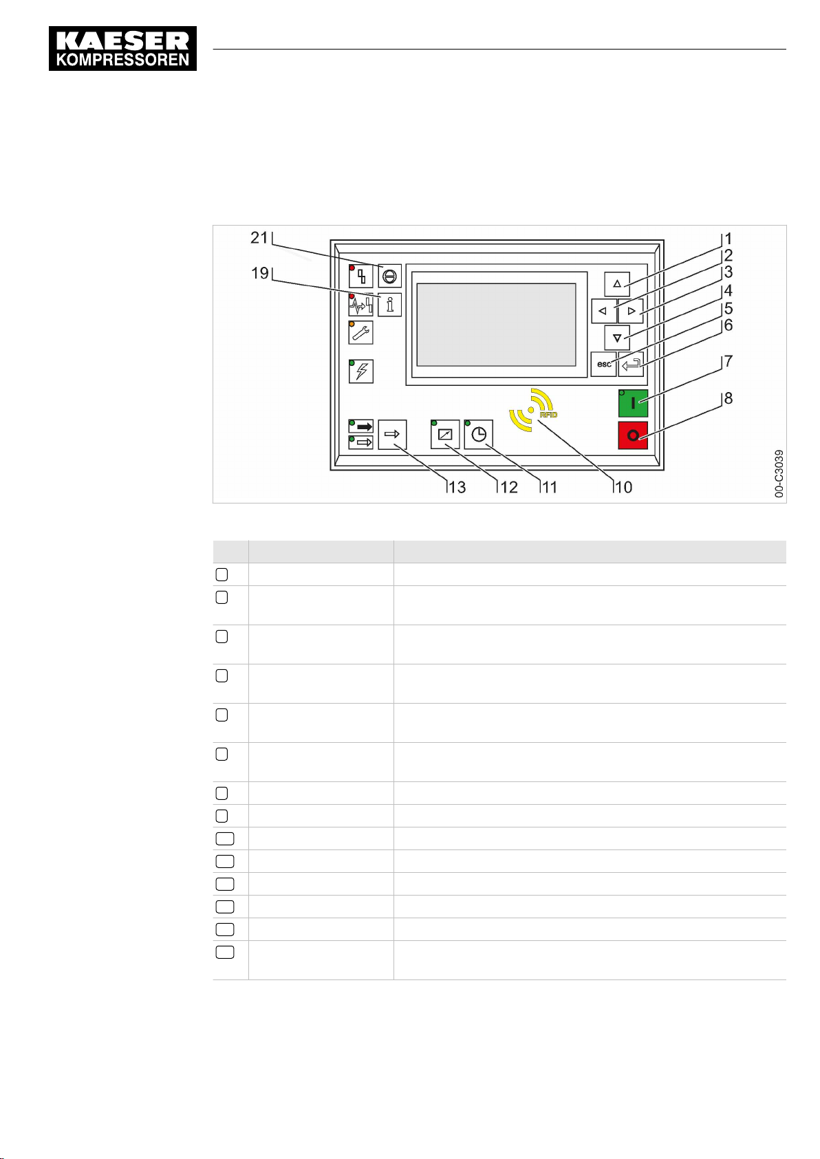
Fig. 1 Operating elements
Item Description Function
1 «Up» Scrolls up the menu options. Increases a parameter value.
2 «Left» Jumps to the left.
3 «Right» Jumps to the right.
4 «Down» Scrolls down the menu options.
5 «Escape» Returns to the next higher menu option level.
6 «Enter» Jumps to the selected submenu option.
7 «ON» Switches the machine on.
8 «OFF» Switches the machine off.
10 RFID RFID reader for user log-in with RFID Equipment Card.
11 «Timer control» Switches the timer control on and off.
12 «Remote control» Switches the remote control on and off.
13 «LOAD/IDLE» Toggles between the LOAD and IDLE modes.
19 «Information» Displays the event memory.
21 «Acknowledgement» Confirms/acknowledges alarms and warning messages.
Moves the cursor position to the next left field.
Moves the cursor position to the next right field.
Reduces a parameter value.
Exits the edit mode without saving.
Exits the edit mode and saves.
If permissible: Resets the fault counter (RESET).
No.: 9_9450 07 USE
Tab. 1 Operating elements
User Manual Controller
SIGMA CONTROL 2 SCREW FLUID ≥4.0.X
1
Page 12
1 SIGMA CONTROL 2 Quick installation guide
1.2 Display elements
1.2 Display elements
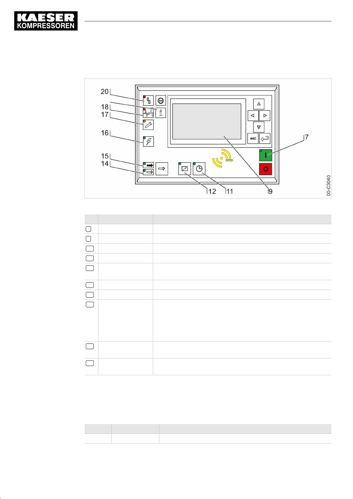
Fig. 2 Display elements
Item Description Function
7
ON
9
Display
11
Timer control
12
Remote control
14
IDLE
15
LOAD
16
Controller voltage
17
Warning
18
Communications
error
20
Alarm
Display illuminates green when the machine switched on.
Graphic display with 8 lines and 30 characters per line.
Continuous green light when the machine is controlled by the timer.
Continuous green light when the machine is in remote control.
Continuous green light when the machine is running in IDLE. Flashes
when the «LOAD/IDLE» toggle key is pressed.
Continuous green light when the machine is running in LOAD.
Continuous green light when voltage is applied to the controller.
Flashes in yellow in the following events:
■ Maintenance work due
■ Warning message
Continuous yellow light after acknowledgement.
Continuous red light to indicate a defective communication connection,
or an external alarm message without machine shutdown.
Flashes red to indicate a machine alarm.
Continuous red light after acknowledgement.
Tab. 2 Display elements
1.3 Main menu
Press «Up» / «Down» / «Enter» to open the main menu.
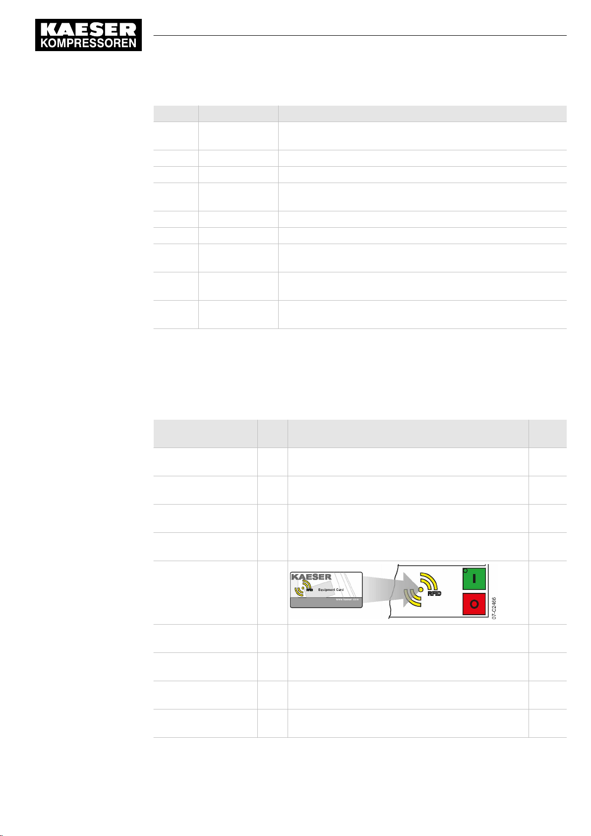
Menu No. Menu designation Function
1 Status Displays messages, statistics and status information.
User Manual Controller
2
SIGMA CONTROL 2 SCREW FLUID ≥4.0.X No.: 9_9450 07 USE
Page 13
1 SIGMA CONTROL 2 Quick installation guide
1.4 Functions – Overview
Menu No. Menu designation Function
2 Performance data Displays measured data of the machine and its components (e.g.,
motors).
3 Operating data Displays operating hours, switching cycles and energy data.
4 Maintenance Displays maintenance data of the machine and its components.
5 Configuration Setting of machine parameters, compressed air system and acces‐
sories.
6 Compressor clock Setting the timer control.
7 User Manual user log-in and password administration.
8 Communication Setting the Ethernet interface, COM modules and control center
connection.
9 Machine test Safety relief valve and temperature sensor test and shutdown at ex‐
cessive temperature.
10 Components Display of settings on machine components, e.g. the power switch‐
ing unit.
Tab. 3 Main menu
See Chapter 5.6.2 for the complete menu structure.
1.4 Functions – Overview
Function Menu
No.
Setting the contrast Main
menu
Setting the brightness Main
menu
Setting the language Main
menu
Setting date, time and
time zone
Identification with
RFID Equipment Card
5.1
– 8.2.4
Action steps Chapter
Press and hold «Information» – «Up» / «Down». 8.2.11
Press and hold «Information» – «Left» / «Right». 8.2.11
«Enter» – «Up» – «Enter» – «Up» / «Down». 8.2.2
<Configuration – General>
. 8.2.7
No.: 9_9450 07 USE
Setting pressure pa‐
rameters
Setting the
«Timer control»
Activating the
«Timer control» key
Activating
«Timer control»
User Manual Controller
SIGMA CONTROL 2 SCREW FLUID ≥4.0.X
5.2.2
<Configuration – Pressure control – Pressure settings –
pA/pB>
6
6
– Activate the «Timer control» key – Press
<Compressor clock – Setting timing program>
<Compressor clock – Key clock – ☑>
«Timer control».
8.4
.
. 8.5.1
. 8.5.1.3
8.5.1.4
3
Page 14

1 SIGMA CONTROL 2 Quick installation guide
1.4 Functions – Overview
Function Menu
No.
Activate
the «Remote control»
key
Activating the
«Remote control»
Setting the control
mode
Setting up the holiday
period
Displaying operating
data
Setting the mainte‐
nance interval
Checking the safety re‐
lief valve
High temperature shut‐
down test
Alarm messages 1.1.1 An alarm message causes the machine to shut down.
Warning messages 1.1.1 If maintenance work is to be carried out or if the warning
Operational messages 1.1.1 Operational messages provide information about the
Diagnostic messages 1.1.1 A diagnostic message causes the machine to shut
System messages 1.1.1 A system message causes the machine to shut down.
5.2.3
5.4.1
5.5
– Activate the «Remote control» key – Press
5.3 Select
5.4.2
3
4
9.1 For the test process, see Chapter. 9.11
9.1 For the test process, see Chapter. 9.12
Action steps Chapter
<Configuration – Compressor start – Compressor on –
Key remote – ☑>
«Remote control».
.
<Configuration – Control mode – Local mode –
Control mode>
.
<Configuration – Compressor start – Compressor off –
Holidays – Start/End/☑>
.
<Operating data – Operating hours / Switching cycles>
<Maintenance – Select/set component>
The
Alarm
LED flashes red. Alarm messages are identi‐
fied with the letter A. Example:
<0002 S k 31/12/2017 13:14:15 Motor temperature ⇞> .
is displayed before an alarm, the yellow
flashes. Warning messages are identified with the let‐
ter W.
current operational state of the machine. Operational
messages are identified with the letter O.
down. They provide information on the status of the con‐
troller, the connected input and output modules and sup‐
port an authorized KAESER service representative in
troubleshooting. Diagnostic messages are identified with
the letter D.
System messages are identified with the letter Y.
. 9.10
Warning
LED
8.2.12
8.2.12
8.6.1
8.5.2
. 9.8
10.2
10.3
10.4
10.5
10.6
Tab. 4 Functions – Overview
Settings can be made after log-in with the RFID Equipment Card and password access level
2.
User Manual Controller
4
SIGMA CONTROL 2 SCREW FLUID ≥4.0.X No.: 9_9450 07 USE
Page 15

2 Regarding this Document
2.1 Using this document
2 Regarding this Document
2.1 Using this document
The user manual contains important information to the entire life cycle of SIGMA CONTROL 2.
The user manual is a component of the product.
➤ Keep the user manual in a safe place throughout the life of SIGMA CONTROL 2.
➤ Pass the user manual on to the next owner/user of the machine.
➤ Ensure that all amendments received are inserted into the user manual.
2.2 Copyright
This user manual is protected by copyright. Any queries regarding the use or duplication of this
documentation should be referred to KAESER. Correct use of information will be fully supported.
2.2.1 Software
The software used in SIGMA CONTROL 2 contains copyright-protected software packages which
are licensed as Open Source.
A copy of these licenses is contained in SIGMA CONTROL 2.
Display the licenses by pointing your browser to the "COPYING" file in the root directory of
SIGMA CONTROL 2.
URL:
http:// <Hostname>/COPYING
The licenses can also be found under these addresses:
http://www.gnu.org/licenses
http://code.google.com/p/curve25519-donna/
Within three years from receipt of SIGMA CONTROL 2, you may obtain the complete source code
by sending a corresponding order to the following address:
Technical Office Electrical Design
KAESER KOMPRESSOREN SE
96450 Coburg, Postfach 2143
Germany
This offer is valid for anybody having this information.
No.: 9_9450 07 USE
User Manual Controller
SIGMA CONTROL 2 SCREW FLUID ≥4.0.X
5
Page 16

2 Regarding this Document
2.3 Approvals
2.3 Approvals
The product has the following approvals:
■ This equipment has been tested and found to comply with the limits for a Class B digital de‐
vice, pursuant to Part 15 of the FCC Rules. These limits are designed to provide reasonable
protection against harmful interference in a residential installation. This equipment generates,
uses and can radiate radio frequency energy and, if not installed and used in accordance with
the instructions, may cause harmful interference to radio communications. However, there is
no guarantee that interference will not occur in a particular installation. If this equipment does
cause harmful interference to radio or television reception, which can be determined by turning
the equipment off and on, the user is encouraged to try to correct the interference by one of the
following measures:
─ Reorient or Relocate the receiving antenna
─ Increase the separation between the equipment and receiver
─ Connect the equipment into an outlet on a circuit different from that to which the receiver is
connected
─ Consult the dealer or an experienced radio/TV technician for help
■ To assure continued compliance, any changes or modifications not expressly approved by the
party responsible for compliance could void the user's authority to operate this equipment. (Ex‐
ample - use only shielded interface cables when connecting to computer or peripheral devi‐
ces).
■ This device complies with Part 15 of the FCC Rules. Operation is subject to the following two
conditions:
─ This device may not cause harmful interference, and
─ This device must accept any interference received, including interference that may cause
undesired operation
■ This device complies with Industry Canada licence-exempt RSS standard(s). Operation is sub‐
ject to the following two conditions:
─ This device may not cause interference and
─ This device must accept any interference, including interference that may cause undesired
operation of the device
■ Le présent appareil est conforme aux CNR d'Industrie Canada applicables aux appareils radio
exempts de licence. L'exploitation est autorisée aux deux conditions suivantes :
─ l'appareil ne doit pas produire de brouillage, et
─ l'utilisateur de l'appareil doit accepter tout brouillage radioélectrique subi, même si le brouil‐
lage est susceptible d'en compromettre le fonctionnement
2.4 Updating the user manual
The page http://www.kaeser.com/int-en/manuals/response.aspx of our website provides frequently
updated versions of this user manual.
➤ Download the user manual in your language.
2.5 Symbols and labels
➤ Please note the symbols and labels used in this document.
User Manual Controller
6
SIGMA CONTROL 2 SCREW FLUID ≥4.0.X No.: 9_9450 07 USE
Page 17
2 Regarding this Document
2.5 Symbols and labels
2.5.1 Warnings
Warning notices indicate dangers that may result in injury when disregarded.
Warning notices indicate three levels of danger identified by the corresponding signal word:
Signal term Meaning Consequences of non-compliance
DANGER Warns of an imminent danger Will result in death or severe injury
WARNING Warns of a potentially imminent danger May result in death or severe injury
CAUTION Warns of a potentially dangerous situation May result in a moderate physical injury
Tab. 5 Danger levels and their definition (personal injury)
Warning notices preceding a chapter apply to the entire chapter, including all sub-sections.
Example:
The type and source of the imminent danger is shown here!
The possible consequences of ignoring a warning are shown here.
If you ignore the warning notice, the "DANGER" signal word indicates a lethal or severe in‐
jury will occur.
➤ The measures required to protect yourself from danger are shown here.
Warning notes referring to a sub-section or the subsequent action are integrated into the procedure
and numbered as an action.
Example:
1.
The type and source of the imminent danger is shown here!
The possible consequences of ignoring a warning are shown here.
If you ignore the warning notice, the "WARNING" signal word indicates that a lethal or severe
injury may occur.
➤ The measures required to protect yourself from danger are shown here.
2. Always read and comply with warning instructions.
2.5.2 Potential damage warnings
Contrary to the warnings shown above, damage warnings do not indicate a potential personal in‐
jury.
Warning notices for damages are identified by their signal term.
Signal term Meaning Consequences of non-compliance
NOTE Warns of a potentially dangerous situation Damage to property is possible
No.: 9_9450 07 USE
Tab. 6 Danger levels and their definition (damage to property)
Example:
User Manual Controller
SIGMA CONTROL 2 SCREW FLUID ≥4.0.X
7
Page 18
2 Regarding this Document
2.5 Symbols and labels
The type and source of the imminent danger is shown here!
Potential effects when ignoring the warning are indicated here.
➤ The protective measures against the damages are shown here.
➤ Carefully read and fully comply with warnings against damages.
2.5.3 Other alerts and their symbols
The meaning of names is emphasized by different formatting. Depending on the font, not all for‐
matting options can be realized.
Name Formatting Example
Operating state UPPER CASE LOAD
Item number ... Open valve 4
Indication
Key « ... » «ON» key
Menu option
Menu path
activated ... The minutes display flashes. 00:00:00
italic ON
< ... > <Configuration>
<Menu 1 – Menu 2 – ...> <Configuration – Pressure control>
LED
Tab. 7 Formatting options
This symbol identifies particularly important information.
Material Here you will find details on special tools, operating materials or spare parts.
Precondition Here you will find conditional requirements necessary to carry out the task.
The conditions relevant to safety shown here will help you to avoid dangerous situations.
➤ This symbol denotes lists of actions comprising one stage of a task.
Operating instructions with several steps are numbered in the sequence of the operating steps.
Information referring to potential problems are identified by a question mark.
The cause is named in the help text ...
➤ ... as is a solution.
This symbol identifies important information or measures regarding the protection of the envi‐
ronment.
Further information Further subjects are introduced here.
User Manual Controller
8
SIGMA CONTROL 2 SCREW FLUID ≥4.0.X No.: 9_9450 07 USE
Page 19
3 Technical Data
3.1 SIGMA CONTROL 2 Controller
3 Technical Data
3.1 SIGMA CONTROL 2 Controller
Industrial computer
■ Internal temperature monitoring
■ Internal low voltage monitoring
■ Battery-buffered real-time clock
─ Battery service span more than 10 years
─ Battery replaceable
3.1.1 Versions and options
SIGMA CONTROL 2 is offered in different designs.
Type Prepared for connection to control center Connection to control technology not
provided
Option C3 C48
Compo‐
nents
Tab. 8 Versions and options
Main Control System (MCS): Slot for an
optional communication module (to con‐
nect to a control center)
Input-Output-Module (IOM): Modules with
digital and analog inputs and outputs.
Main Control System Input Output
(MCSIO): Digital and analog inputs and
outputs integrated
3.1.2 User interface with display, CPU and interfaces
User interface
Feature MCS MCSIO
Material Plastics
Width [in.] 7.5
Height [in.] 5.1
Depth [in.] 1.8 2.4
Number of membrane keys 13
Number of LEDs 9
Degree of protection, control cabinet exterior IP 54
Degree of protection, control cabinet interior IP 20
Voltage [V] 24
Current [A] 0.3 2.5
Voltage source Input/output module External
No.: 9_9450 07 USE
Tab. 9 User interface
User Manual Controller
SIGMA CONTROL 2 SCREW FLUID ≥4.0.X
9
Page 20
3 Technical Data
3.1 SIGMA CONTROL 2 Controller
Display
Feature Value
Graphical display [px] 255 x 128
Width [in.] 3.2
Height [in.] 1.6
Maximum number of lines/characters 8/30
Colors Black/white with grey scale
Lighting LED backlit
px = pixel
Tab. 10 Display data
10
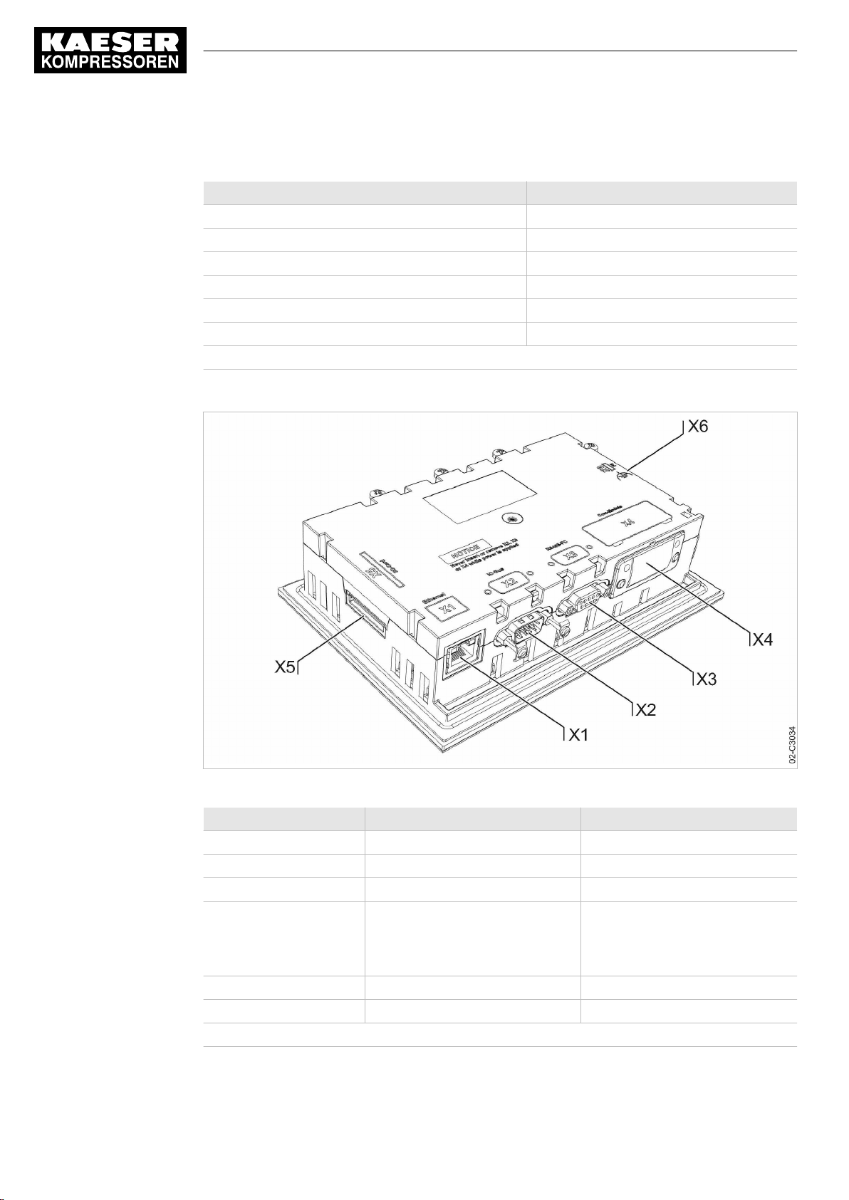
Fig. 3 MCS interfaces
Identification Interface Connection
X1 Ethernet 10/100 Base T RJ 45 socket
X2 I/O bus 9-pole SUB-D pins
X3 RS485–FC (USS interface) 9-pole SUB-D socket
X4 Com modules,
X5 SD card, SD card slot SD/SDHC card
X6 FG Functional ground (FG)
The positions of the interfaces X1–X6 are marked on the rear of the controller.
Tab. 11 MCS interfaces
User Manual Controller
SIGMA CONTROL 2 SCREW FLUID ≥4.0.X No.: 9_9450 07 USE
slot for communications module
Module optional for:
PROFIBUS, PROFINET,
Modbus RTU, Modbus TCP,
DeviceNet
Page 21
3 Technical Data
3.1 SIGMA CONTROL 2 Controller
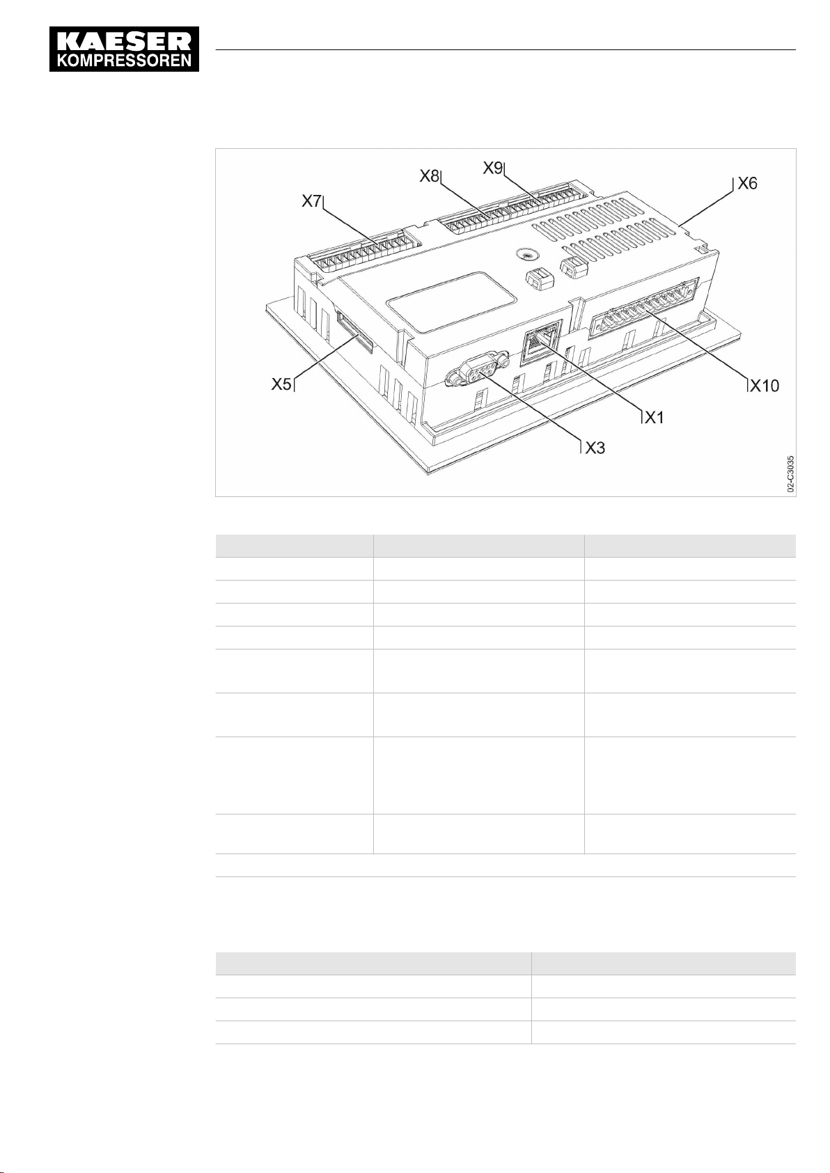
Fig. 4 MCSIO interfaces
Marking Interface Connection
X1 Ethernet 10/100 Base T RJ 45 socket
X3 RS485–FC (USS interface) 9-pole SUB-D socket
X5 SD card, SD card slot SD/SDHC card
X6 FG Functional ground (FG)
X7 24 VDC, DII Power supply 24 VDC
X8 DII/DOT Digital inputs DII1.06–DII1.07
X9 AII/AIR Analog input current 0–20 mA,
X10 DOR Digital output relay 250 VAC, 4 A
The positions of the interfaces X1–X10 are marked on the rear of the controller.
Tab. 12 MCSIO interfaces
Digital inputs DII1.00–DII1.05
Digital outputs DOT1.00–DOT1.01
AII1.00–AII1.01
Analog input resistor AIR1.00–
AIR1.01
DOR1.00–DOR1.04
No.: 9_9450 07 USE
Identification with RFID Equipment Card
Feature Value
Hardware on the SIGMA CONTROL 2 controller RFID write/read device
Hardware (external) RFID Equipment Card
Recognition distance [in.] Max. 2
User Manual Controller
SIGMA CONTROL 2 SCREW FLUID ≥4.0.X
11
Page 22
3 Technical Data
3.1 SIGMA CONTROL 2 Controller
Feature Value
Frequency [MHz] 13.56
Tab. 13 RFID
3.1.3 Inputs and outputs with MCSIO
Integrated inputs and outputs with MCSIO type controller
Input/Output Number
Digital input (DI), 24 VDC 8
Digital output transistor (DOT), 24 VDC, 0.5 A 2
Analog input current (AII), 0–20 mA 2
Analog input resistor (AIR), PT100 2
Digital output relay (DOR), 250 VAC, 4 A 5
Tab. 14 MCSIO inputs and outputs
3.1.3.1 Maximum cable lengths
Input/Output Cable length [ft.]
Analog input current (AII),
Analog input resistor (AIR)
Analog output current (AOI)
Digital input (DI),
Digital output relay (DOR)
Digital output transistor (DOT) < 100
Tab. 15 Cable lengths
3.1.4 Input/output modules
IOM modules only in combination with the MCS controller type
There are three different types of input/output modules with different numbers of inputs and out‐
puts.
The number of input/output modules actually available depends on the machine type and the avail‐
able options.
Refer to the machine's wiring diagram for the input/output modules installed in your equipment.
< 100
< 330
12
The input/output module features:
■ Internal temperature monitoring
■ Internal low voltage monitoring
■ LED indication of operational status
User Manual Controller
SIGMA CONTROL 2 SCREW FLUID ≥4.0.X No.: 9_9450 07 USE
Page 23
3 Technical Data
3.1 SIGMA CONTROL 2 Controller
IOM 1
Input/Output Input/output module 1
Digital input (DI), 24 VDC 4 10 2
Analog input current (AII), 0–20 mA – 1 2
Analog input resistor (AIR), PT100 – 1 3
Digital output relay (DOR), 250 VAC, 8 A 8 – –
Digital output transistor (DOT), 24 VDC, 0.5 A – 2 1
Analog output current (AOI), 0–20 mA – – –
Tab. 16 IOM 1
IOM 2
Input/Output Input/output module 2
Digital input (DI), 24 VDC 6 – 2
Analog input current (AII), 0–20 mA – 1 2
Analog input resistor (AIR), PT100 – 3 –
Digital output relay (DOR), 250 VAC, 8 A 4 – –
Digital output transistor (DOT), 24 VDC, 0.5 A – 2 2
Analog output current (AOI), 0–20 mA – 1 –
Internal, into
the control
cabinet
Internal, into
the control
cabinet
Available in
parallel on
both sides
Available in
parallel on
both sides
External, into
the compres‐
sor interior
External, into
the compres‐
sor interior
Tab. 17 IOM 2
IOM 3
Input/Output Input/output module 3
Digital input (DI), 24 VDC 6 – 2
Analog input current (AII), 0–20 mA – 1 3
Analog input resistor (AIR), PT100 – 3 8
Digital output relay (DOR), 250 VAC, 8 A 8 – –
Digital output transistor (DOT), 24 VDC, 0.5 A – 1 1
Analog output current (AOI), 0–20 mA – 1 –
Tab. 18 IOM 3
Internal, into
the control
cabinet
Available in
parallel on
both sides
External, into
the compres‐
sor interior
No.: 9_9450 07 USE
User Manual Controller
SIGMA CONTROL 2 SCREW FLUID ≥4.0.X
13
Page 24
3 Technical Data
3.1 SIGMA CONTROL 2 Controller
3.1.4.1 Electrical connection specifications IOM
Power is provided by the power supply unit within the machine.
Feature Value
Rated power supply (stabilized) [V DC] 24
Current consump‐
tion SIGMA CONTROL 2 with IOM 1 [A]
Current consumption IOM 2 [A] 2.5
Current consumption IOM 3 [A] 1.6
IOM = Input/Output module
Tab. 19 Power supply specifications
3.1.4.2 Maximum cable lengths
Input/Output Conductor length [ft.]
Analog input current (AII),
Analog input resistor (AIR)
Analog output current (AOI)
Digital input (DI),
Digital output relay (DOR)
Digital output transistor (DOT) < 100
2.4
< 100
< 330
Tab. 20 Cable lengths
3.1.4.3 Input/output module – degree of protection
Feature Value
Degree of protection within the machine IP 54
Degree of protection within the control cabinet IP 20
Tab. 21 IOM degree of protection
3.1.4.4 Input/output modules – dimensions
Feature Value
Width [in.] 4.9
Height [in.] 9.8
Depth [in.] 1.7
Tab. 22 IOM dimensions
3.1.5 Sensors
Pressure transducer
14
Feature Value
Output signal [mA] 0/4–20
User Manual Controller
SIGMA CONTROL 2 SCREW FLUID ≥4.0.X No.: 9_9450 07 USE
Page 25

3 Technical Data
3.1 SIGMA CONTROL 2 Controller
Feature Value
Connection Twin cable
Tab. 23 Pressure transducer
Resistance thermometer
Feature Value
Sensing resistance PT100
Connection Twin cable
Tab. 24 Resistance thermometer
No.: 9_9450 07 USE
User Manual Controller
SIGMA CONTROL 2 SCREW FLUID ≥4.0.X
15
Page 26

4 Safety and Responsibility
4.1 Basic instructions
4 Safety and Responsibility
4.1 Basic instructions
This equipment has been tested and found to comply with the limits for a Class B digital de‐
vice, pursuant to part 15 of the FCC Rules.
These limits are designed to provide reasonable protection against harmful interference in a
residential installation. This equipment generates, uses and can radiate radio frequency ener‐
gy and, if not installed and used in accordance with the instructions, may cause harmful inter‐
ference to radio communications.
However, there is no guarantee that interference will not occur in a particular installation.
If this equipment does cause harmful interference to radio or television reception, which can
be determined by turning the equipment off and on, the user is encouraged to try to correct
the interference by one or more of the following measures:
➤ Close and lock the door of the equipment properly.
➤ Place the equipment as far as possible from the interfered radio or television receiver.
Changes or modifications not expressly approved by KAESER could void the user's authority
to operate the equipment.
This device complies with Industry Canada licence-exempt RSS standard(s).
Operation is subject to the following two conditions:
■ this device may not cause interference and
■ this device must accept any interference, including interference that may cause unde‐
sired operation of the device
SIGMA CONTROL 2 is manufactured to the latest engineering standards and acknowledged safety
regulations.
The safety regulations of the machine in which SIGMA CONTROL 2 is installed apply.
4.2 Specified use
SIGMA CONTROL 2 is solely intended for the control of machines in which SIGMA CONTROL 2 is
factory-installed. Any other use is considered incorrect. The manufacturer is not liable for any dam‐
ages that may result from incorrect use. The user alone is liable for any risks incurred.
➤ Adhere to the specifications given in this user manual and the machine's operator manual.
➤ Operate the machine only within its performance limits and under the permitted ambient condi‐
tions.
4.3 Improper use
Improper usage can cause damage to property and/or (severe) injuries.
➤ Use SIGMA CONTROL 2 only as intended.
➤ Do not use SIGMA CONTROL 2 to control other machines or products for which
SIGMA CONTROL 2 is not intended.
16
User Manual Controller
SIGMA CONTROL 2 SCREW FLUID ≥4.0.X No.: 9_9450 07 USE
Page 27

5 Design and Function
5.1 The controller
5 Design and Function
5.1 The controller
SIGMA CONTROL 2 controls, regulates, monitors, and protects the machine.
All parameters needed to operate KAESER rotary screw compressors can be set and displayed
using the controller. Various user-dependent password mechanisms protect the parameters.
Components
SIGMA CONTROL 2 has the following components:
■ Main Control System (MCS):
─ Industrial PC.
─ Software for the control, regulation, and monitoring of the machine, for the display and mod‐
ification of settings and for communication.
─ User interface with backlit display, touch keys, LEDs, and interfaces.
─ Radio Frequency Idenfication (RFID):
Identification with RFID Equipment Card.
─ Slot for customer interface; optional communications module.
─ SD card slot for SD/SDHC cards:
Manual loading of updates with an SC card, reading or recording process data.
■ Main Control System Input Output (MCSIO):
─ As with MCS, but with:
─ Integrated digital and analog inputs and outputs.
─ Without slot for customer interface.
■ Input-Output-Module (IOM):
For SIGMA CONTROL 2 (Prepared for connection to control center): modules with digital and
analog inputs and outputs with autonomous power supply.
No.: 9_9450 07 USE
User Manual Controller
SIGMA CONTROL 2 SCREW FLUID ≥4.0.X
17
Page 28
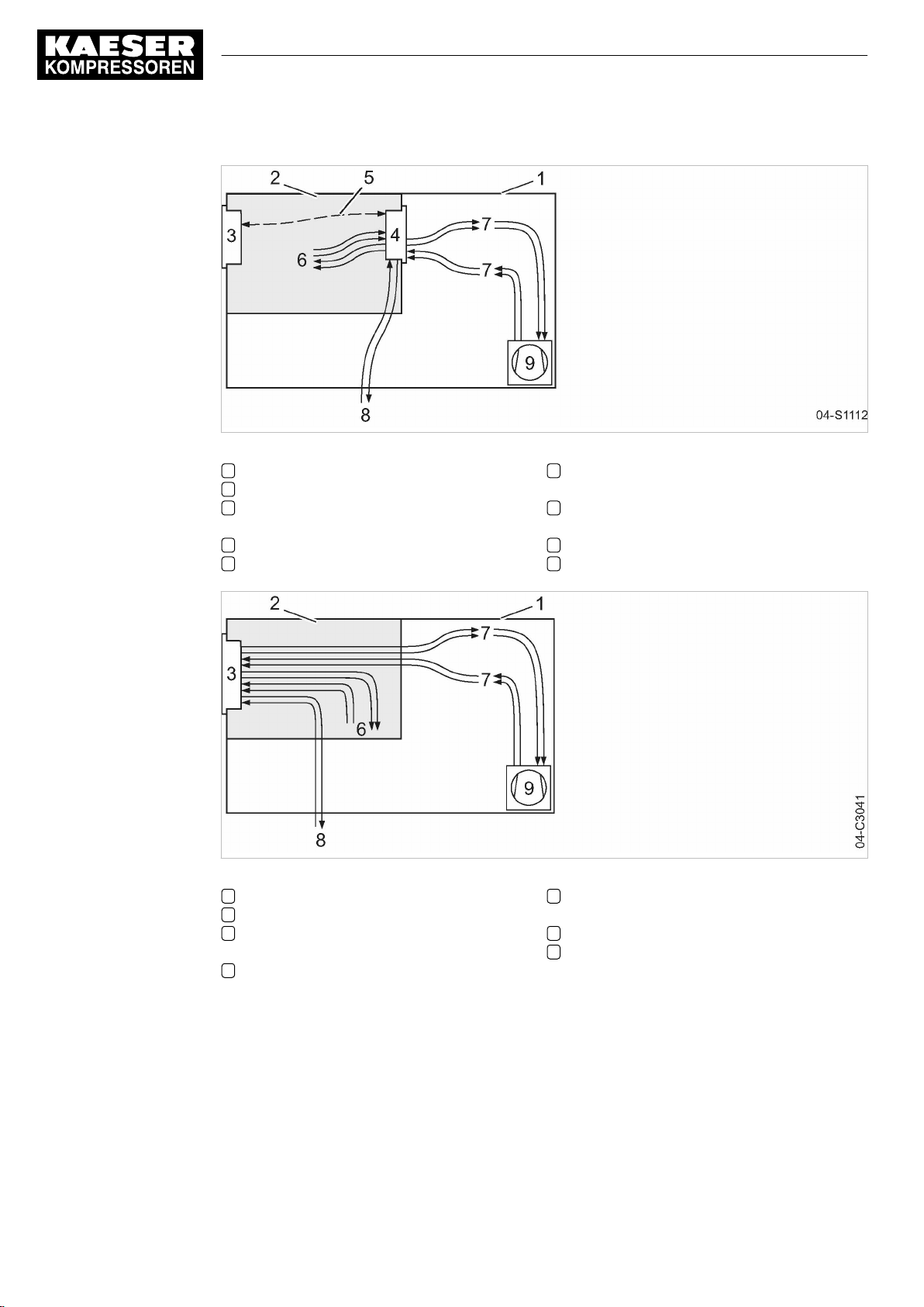
5 Design and Function
5.1 The controller
Fig. 5 MCS system design with IOM
1 Machine enclosure
2 Control cabinet
3 SIGMA CONTROL 2 (Prepared for con‐
nection to control center)
4 Input-Output-Module (IOM):
5 I/O bus
6 Inputs/outputs in the interior of the control
cabinet
7 Inputs/outputs in the interior of the com‐
pressor
8 Inputs/outputs for external sensors
9 Compressor
18
Fig. 6 MCSIO system design
1 Machine enclosure
2 Control cabinet
3 SIGMA CONTROL 2 (Connection to con‐
trol technology not provided)
6 Inputs/outputs in the interior of the control
cabinet
Function
The control and regulating function allows:
■ Automatic changeover of the machine from LOAD to IDLE or READY.
■ Optimum utilization of the drive motor in relation to the user's actual air demand.
■ Automatic restart of the machine after a power failure (can be deactivated).
User Manual Controller
SIGMA CONTROL 2 SCREW FLUID ≥4.0.X No.: 9_9450 07 USE
7 Inputs/outputs in the interior of the com‐
pressor
8 Inputs/outputs for external sensors
9 Compressor
Page 29
5 Design and Function
5.2 Operating panel
The monitoring function allows:
■ Supervision of all maintenance-relevant components via the maintenance interval counters.
■ Display of warning and maintenance messages for due maintenance on the display
of SIGMA CONTROL 2.
The protective function allows:
■ Automatic machine shutdown on alarms that may lead to damage to the machine, e.g. high
current, high pressure or high temperature.
5.2 Operating panel
5.2.1 Indicating and operating elements
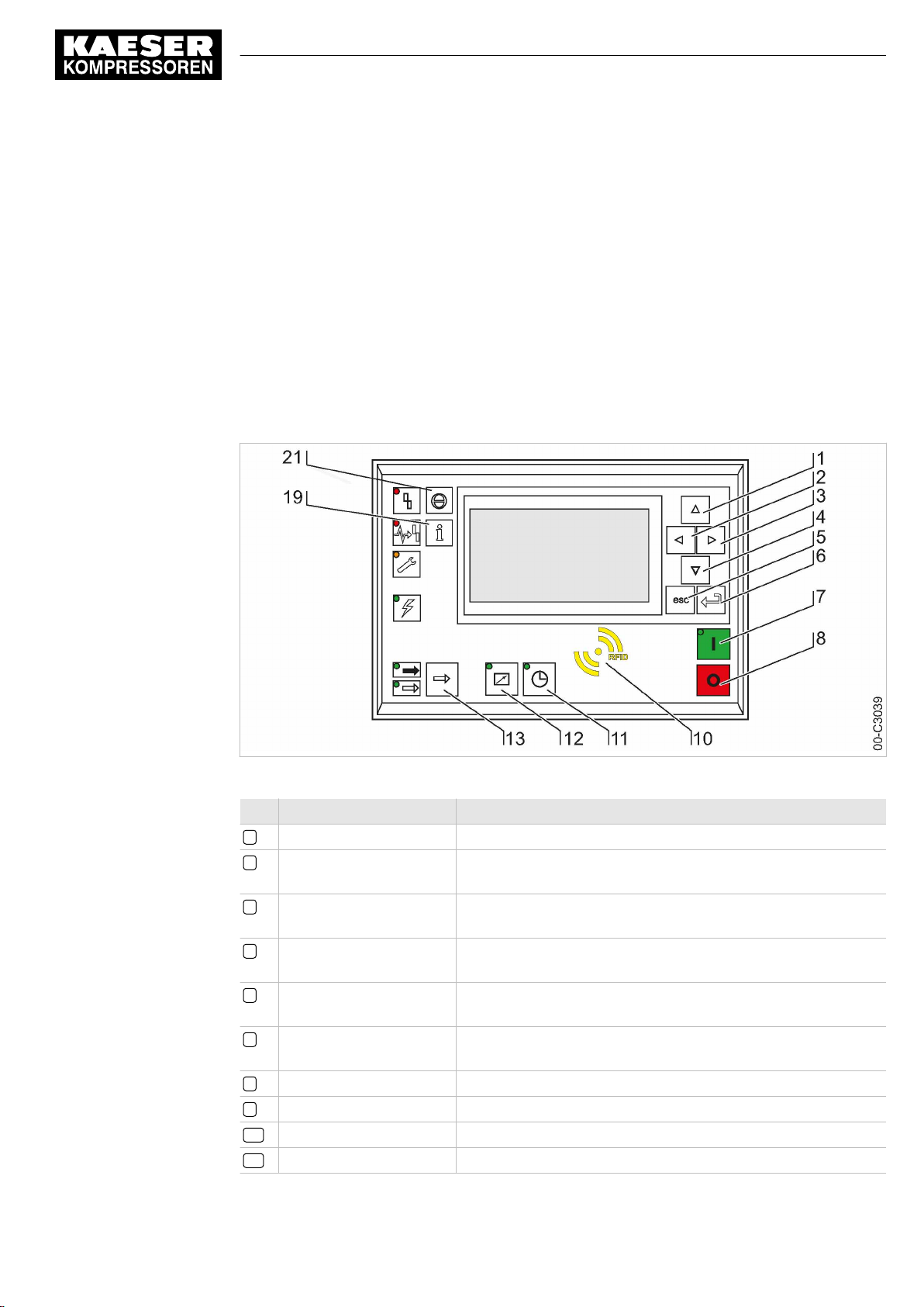
Fig. 7 Indicating and operating elements
Item Description Function
1 «Up» Scrolls up the menu options. Increases a parameter value.
2 «Left» Jumps to the left.
3 «Right» Jumps to the right.
4 «Down» Scrolls down the menu options.
5 «Escape» Returns to the next higher menu option level.
6 «Enter» Jumps to the selected menu option.
7 «ON» Switches the machine on.
8 «OFF» Switches the machine off.
10 RFID RFID reader for user log-in with RFID Equipment Card.
11 «Timer control» Switches the timer control on and off.
Moves the cursor position to the next left field.
Moves the cursor position to the next right field.
Reduces a parameter value.
Exits the edit mode without saving.
Exits the edit mode and saves.
No.: 9_9450 07 USE
User Manual Controller
SIGMA CONTROL 2 SCREW FLUID ≥4.0.X
19
Page 30
5 Design and Function
5.2 Operating panel
Item Description Function
12 «Remote control» Switches the remote control on and off.
13 «LOAD/IDLE» Toggles between the LOAD and IDLE modes.
19 «Information & Events» Displays the event memory.
21 «Acknowledgement» Confirms/acknowledges alarms and warning messages.
Tab. 25 Operating elements
5.2.2 Display elements
If permissible: Resets the fault counter (RESET).
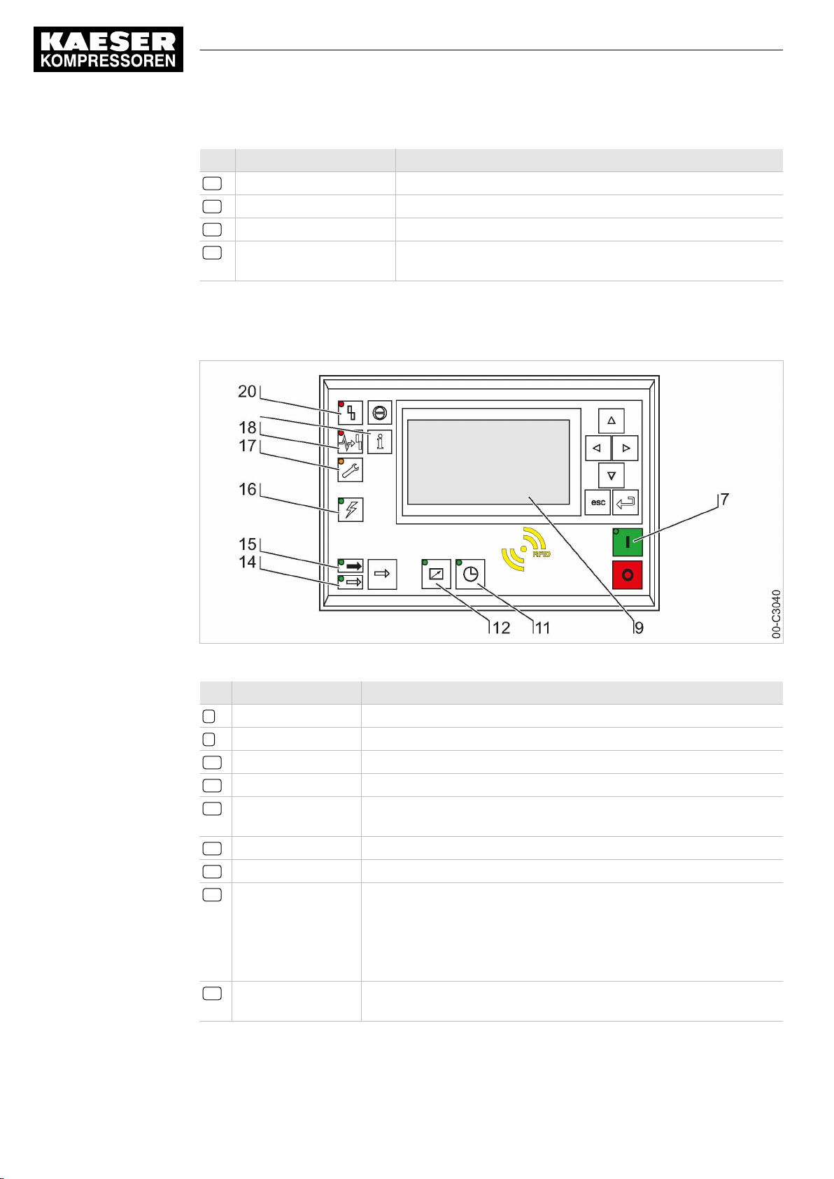
Fig. 8 Display elements
Item Description Function
7
ON
9
Display
11
Timer control
12
Remote control
14
IDLE
15
LOAD
16
Controller voltage
17
Warning
18
Communications
error
Continuous green light when the machine switched on.
Graphic display with 8 lines and 30 characters per line.
Continuous green light when the machine is controlled by the timer.
Continuous green light when the machine is in remote control.
Continuous green light when the machine is running in IDLE. Flashes
when the «LOAD/IDLE» toggle key is pressed.
Continuous green light when the machine is running in LOAD.
Continuous green light when voltage is applied to the controller.
Flashes in yellow in the following events:
■ Maintenance necessary
■ Warning message
Continuous yellow light after acknowledgement.
Continuous red light to indicate a defective communication connection,
or an external alarm message without machine shutdown.
20
User Manual Controller
SIGMA CONTROL 2 SCREW FLUID ≥4.0.X No.: 9_9450 07 USE
Page 31
5 Design and Function
5.3 Display
Item Description Function
20
Alarm
Tab. 26 Display elements
5.2.3 RFID reader
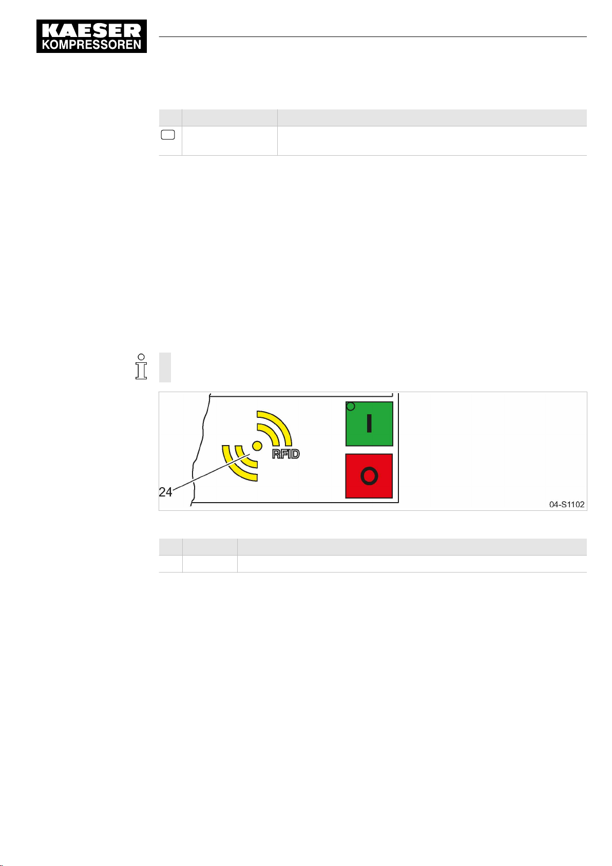
RFID is the abbreviation for “Radio Frequency Identification” and makes possible to identify per‐
sons and objects.
Placing a suitable transponder in front of the RFID reader of the controller will automatically acti‐
vate the communication between transponder and SIGMA CONTROL 2.
A suitable transponder is the RFID Equipment Card. Two of them have been provided with the ma‐
chine.
Typical application:
■ Operators log on at the machine.
(Manual input of the password not required)
Flashes red to indicate a machine alarm.
Continuous red light after acknowledgement.
The RFID Equipment Cards are carefully packed in a plastic sleeve.
This plastic sleeve is attached to the rear of the controller in the control cabinet.
Fig. 9 RFID reader
Item Description Function
24 RFID RFID reader for the communication with a RFID Equipment Card or RFID Key.
Tab. 27 RFID reader
5.3 Display
Use the display to read information and to enter data. The display comprises 8 lines, each of 30
characters.
During operation, the display will indicate the operating mode.
Pressing «Enter» or one of the arrow keys opens the main menu. Here, you can set the language
to be used for the display of texts or open the various submenus.
No.: 9_9450 07 USE
User Manual Controller
SIGMA CONTROL 2 SCREW FLUID ≥4.0.X
21
Page 32

5 Design and Function
5.3 Display
5.3.1 Operating mode
8 8 p s i 0 8 : 1 5 A M 1 7 6 ° F
__________________________________
Load
__________________________________
Key – on ¦ pA – on
__________________________________
Run 2500h Load 2490h
Maintenance in 500h
Header
The header is the topmost line on the display. It is always shown as white text on a black back‐
ground.
Important information and values are displayed in the header.
The displayed data varies depending on the machine type:
Type Header, left Header, center Header, right
SIGMA CONTROL 2
FLUID
SIGMA CONTROL 2
DRY
SIGMA CONTROL 2
VAC
SIGMA CONTROL 2
BOOSTER
Working pressure Time Airend discharge temperature
Working pressure Time Airend discharge temperature
Working pressure Time Airend discharge temperature
Pressure at the com‐
pressed air inlet p1
Header
Current operating mode
Operating parameters
Operating parameters
Maintenance indicator
Temperature at the
compressed air
outlet T2
Pressure at the compressed
air outlet p4
Tab. 28 Header
Lines 3 and 5: Operational state
Depending on the settings, either the current state of the machine or a menu text is shown in line 3.
The following parameters with their current values are displayed in line 5:
■ Remote control yes/no
■ Timer control yes/no
■ Pressure control
Lines 7 and 8: Machine state
The following parameters with their current values are displayed in lines 7 and 8:
■ The hours during which the machine was activated.
■ The hours during which the machine ran in operating mode LOAD.
■ Remaining working hours of the machine before the next maintenance.
22
User Manual Controller
SIGMA CONTROL 2 SCREW FLUID ≥4.0.X No.: 9_9450 07 USE
Page 33

5 Design and Function
5.3 Display
5.3.2 Main menu
8 8 p s i 0 8 : 1 5 A M 1 7 6 ° F
Main menu
----------------English US----------------
▶1 Status
▶2 Performance data
▶3 Operating data
▶4 Maintenance
▶5 Configuration
Description
The main menu is the top menu level. You open the individual submenus in the main menu.
A scrollbar appears at the right side of the display if you open a menu with more than 6 lines. It
represents the currently visible portion of the menu. A short scrollbar thus indicates that the opened
menu is very long as only a small portion can be displayed.
The image above provides an example for the appearance of the main menu (without scrollbar).
Language
Active line
Submenu
Submenu
Submenu
Submenu
Numbering
Each menu is numbered.
Not all menus may be displayed because the access to certain menus is restricted by the access
level, and some menus are displayed or hidden due to specific settings or options.
For example, you can recognize subordinate menus in the menu structure by the number preced‐
ing their designation. The menu structure is explained in chapter 5.6.2.
Active line
The active line is always shown as white text on a dark background. Do not confuse this with the
header which is also shown with white lettering on a black background.
Press «Enter» to open a menu in the active line. This opens the selected menu.
Here, you can change parameters.
5.3.3 Setting parameters
In order to set a parameter in the active line of the selected menu, you must always switch to
setting mode.
Changing parameters
Press «Enter». The value of the parameter will flash indicating that it can be changed.
The «Enter» key affects only the active line.
In some lines, you can change more than a single parameter.
In this case, you must first select the specific parameter with the «Left» or «Right» keys.
No.: 9_9450 07 USE
User Manual Controller
SIGMA CONTROL 2 SCREW FLUID ≥4.0.X
23
Page 34
5 Design and Function
5.4 Access rights
Resetting current parameters
In order to reset current parameters to zero, activate the check box for
the display.
First, press «Enter» to switch into setting mode. The check box
You then press «Up». The check box is activated and flashes.
Press «Enter» to save the settings.
The parameters no longer flash and are reset. The check box for
Check box
☒ activated
☐ deactivated
Tab. 29 Reset check box status
Reset
5.3.4 Activating keys with check boxes
Certain keys of the SIGMA CONTROL 2 are locked by default. Activate the corresponding check
boxes in the active line of the display to unlock these keys.
First, press «Enter» to switch into setting mode. The check box will flash.
You then press «Up». The check box is activated and flashes.
Press «Enter» again to save the settings.
The display line no longer flashes and the key is activated.
Proceed correspondingly to deactivate a key.
Check box Status
☑ activated
☐ deactivated
Reset
Status
Reset
in the active line of
will flash.
Reset
is again deactivated.
Tab. 30 Check box status
5.4 Access rights
Access to the controller is governed by the user name combined with a password.
Users log on using an RFID Equipment Card by default. Alternatively, you can manually enter the
user name and the password.
When the controller is switched on, the lowest level of access (level 0) is activated.
You have access to a further level: Access level 2
Access level 2 allows you to display and adjust further parameters.
The access level will automatically return to level 0 after 10 minutes without any key being pressed.
Secure storage of the RFID Equipment Cards
You will receive 2 RFID Equipment Cards with each machine.
They are stored in a plastic sleeve.
This plastic sleeve is attached at the rear of the controller in the control cabinet.
If you lose both RFID Equipment Cards, you can register a new RFID Equipment Card only after
having entered the user name and the password. A new RFID Equipment Card may be registered
by KAESER service subject to a fee, if the user name and the password are lost.
24
User Manual Controller
SIGMA CONTROL 2 SCREW FLUID ≥4.0.X No.: 9_9450 07 USE
Page 35
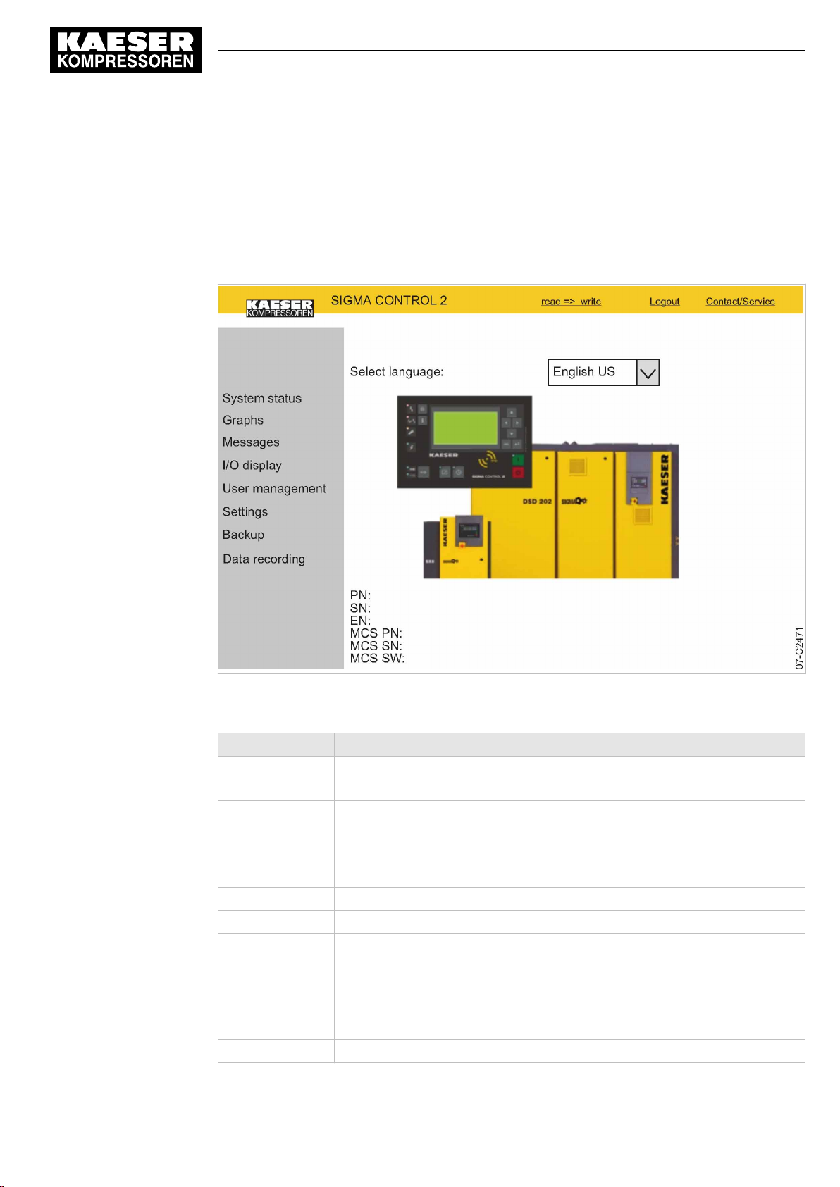
5 Design and Function
5.5 KAESER CONNECT
5.5 KAESER CONNECT
Using an Internet-capable device with web browser, you can open a visualization of the controller.
This enables remote checking of, for example, the operating and energy efficiency of your ma‐
chine. For this purpose, you must once generate a password (see Chapter 8.2.5). KAESER
CONNECT does not require additional software to do so. The display language of KAESER
CONNECT can be set independently to the language used with SIGMA CONTROL 2.
Fig. 10 KAESER CONNECT for SIGMA CONTROL 2
KAESER CONNECT functions:
Operating element Meaning
read => write Switching from read-only to read/write mode
To create users and acknowledge messages
write => read Switching from read/write to read-only mode
Logout User log-out
Contact/Service Displaying the contact information for an authorized KAESER service repre‐
sentative
Select language: Setting the display language for KAESER CONNECT
System status Mapping of the local menu
Graphs ■ Pressures and temperatures are displayed in different graphs
■ Graphic representation of the machine status (STOP, IDLE, LOAD) and
RPM along the time axis
Messages ■ Current messages
■ Message history (event memory)
I/O display Assignment of the input/output modules
No.: 9_9450 07 USE
User Manual Controller
SIGMA CONTROL 2 SCREW FLUID ≥4.0.X
25
Page 36

5 Design and Function
5.6 Menus – overview
Operating element Meaning
User management ■ Creating and activating new user accounts
■ Modifying or deactivating existing user accounts
■ Changing passwords
Settings ■ Unit display format
■ Date display format
■ Time display format
Backup Saving the SIGMA CONTROL 2 data to a PC
Tab. 31 KAESER CONNECT functions
Further information For opening KAESER CONNECT, login and other procedures, please see chapter 8.3.
5.6 Menus – overview
5.6.1 Operating mode
When the machine is switched on, details of the software are displayed, for example:
C o m p r e s s o r
PN: SN:
EN:
SIGMA CONTROL 2 – MCS
PN: SN:
Software:
Subsequently, the software is loaded and the current operating mode is displayed, for example:
8 8 p s i 0 8 : 1 5 A M 1 7 6 ° F
__________________________________
Load
__________________________________
Key – on ¦ pA – on
__________________________________
Run 2500h Load 2490h
Maintenance in 500h
Machine model
Part number and serial number of the machine
Equipment number of the machine
MCS: Main Control System
Part number and serial number of the controller
Software version
Header
Current operating mode
Operating parameters
Operating parameters
Maintenance indicator
26
The following parameters are displayed:
■ Current operating mode of the machine
■ On the left-hand side of "¦" you can see from where the compressor is switched on (in the illus‐
trated example via the green «ON» key) and what the current status is (in the example "on").
■ On the right-hand side of "¦", you can see the mode of the load control (in the illustrated exam‐
ple, the network nominal pressure pA is active) and the mode of the compressor (in the exam‐
ple it is switched on).
■ Number of operating hours and hours of the machine being in LOAD mode.
User Manual Controller
SIGMA CONTROL 2 SCREW FLUID ≥4.0.X No.: 9_9450 07 USE
Page 37

5 Design and Function
5.6 Menus – overview
5.6.2 Menu structure
Press «Enter» or one of the arrow keys to open the main menu.
In the main menu, you can:
■ Retrieve displayed information
■ Enter customer-specific settings
The menus shown require password access level 2.
Main menu
Navigation Function/Submenu
1 Status ■ Messages
■ Statistics
■ Current pressure control
■ Current operating mode
■ DI/DO status
■ pN/ADT curve
■
pN/n curve
1)
For details of the
ble 33.
1)
Power switching with frequency converter
3)
SIGMA CONTROL 2 (Prepared for connection to control technology)
Status
menu, please see ta‐
No.: 9_9450 07 USE
User Manual Controller
SIGMA CONTROL 2 SCREW FLUID ≥4.0.X
27
Page 38

5 Design and Function
5.6 Menus – overview
Navigation Function/Submenu
2 Performance data ■ Compressor
─ System pressure pNloc
─ Internal pressure pi
─ ADT
─ Oil separator
─ Starting temperature
─ Inlet temperature
─ PD temperature
─ Air filter
■ Compressor motor
─ Motor temperature (if available)
─
Speed
─
Current
─
UzK
─
Torque
■ Fan
─
Speed
─
Current
─
UzK
─
Torque
■ Analogue values
■ SIGMA CONTROL 2
3 Operating data ■ Operating hours
─ Compressor
─ On load
─ Motor
─ Compressor block
─ SIGMA CONTROL 2
─ Partial load valves
■ Switching cycles
─ Load valve on
─ Mains contactor on
■ kWh counter
1)
Power switching with frequency converter
3)
SIGMA CONTROL 2 (Prepared for connection to control technology)
1)
1)
1)
1)
1)
1)
1)
1)
28
User Manual Controller
SIGMA CONTROL 2 SCREW FLUID ≥4.0.X No.: 9_9450 07 USE
Page 39

5 Design and Function
5.6 Menus – overview
Navigation Function/Submenu
4 Maintenance Oil filter
Oil separator
Oil change
Air filter
Valve inspection
Belt/coupling inspection
Compressor motor
Bearing lube
Bearing change
Fan motor(s)
Bearing lube
Bearing change
Electrical equipment
Annual maintenance due
5 Configuration For details of the
see table 34.
6 Compressor clock Key clock
Reset
Switching point 01:
Switching point 02:
Switching point 03:
Switching point 04:
Switching point 05:
Switching point 06:
Switching point 07:
Switching point 08:
Switching point 09:
Switching point 10:
7 User Name
Password
Current access level:
8 Communication ■ Ethernet/SIGMA NETWORK
■
Com-Module
Configuration
3)
menu, please
No.: 9_9450 07 USE
Key remote
For details of the
see table 37.
9 Machine test ■ TÜV inspection
1)
Power switching with frequency converter
3)
SIGMA CONTROL 2 (Prepared for connection to control technology)
User Manual Controller
SIGMA CONTROL 2 SCREW FLUID ≥4.0.X
Communication
menu, please
29
Page 40

5 Design and Function
5.6 Menus – overview
Navigation Function/Submenu
10 Components ■ Compressor motor
─ Power switching
1)
Power switching with frequency converter
3)
SIGMA CONTROL 2 (Prepared for connection to control technology)
Tab. 32 Menu structure
5.6.2.1
Status
menu
Navigation Function/Submenu
1.1 Messages ■ Current messages
1.2 Statistics Load (hours)
1)
Power switching with frequency converter
2)
Only visible in the event of parameterization error
3)
SIGMA CONTROL 2 (Prepared for connection to control technology)
For details of the
Components
see table 39.
■ Message history
─ Compressor messages
─ Diagnostic messages
─ System messages
■ Address error
─
Incorrect parameterisation in
Status report
current Alarms
current Warnings
since/Reset:
Load (speed)
1)
since/Reset:
Network actual pressure pNloc
Motor starts
since/Reset:
Motor starts /d
Motor starts /h
Motor starts T↓
Last load run
Last idle run
Last motor off
menu, please
2)
30
User Manual Controller
SIGMA CONTROL 2 SCREW FLUID ≥4.0.X No.: 9_9450 07 USE
Page 41
5 Design and Function
5.6 Menus – overview
Navigation Function/Submenu
1.3 Current pressure control SIGMA CONTROL 2
Cut-out pressure
SP/SD
Network actual pressure
Frequency converter
Setpoint pressure
Actual pressure
Speed nominal value
Speed actual value
Speed limits
1.4 Current operating mode Compressor on
Load control
Control mode
Idle period
Acknowledgement
Waste heat recovery (if available)
1.5 DI/DO status 1st I/O module
DI/DO display
2nd I/O module
DI/DO display
3rd I/O module
DI/DO display
1.6 pN/ADT curve Diagram:
Nominal pressure/Discharge temperature
1.7 pN/n curve
1)
Diagram:
Nominal pressure/Speed
1)
Power switching with frequency converter
2)
Only visible in the event of parameterization error
3)
SIGMA CONTROL 2 (Prepared for connection to control technology)
1)
1)
1)
1)
1)
1)
No.: 9_9450 07 USE
Tab. 33
Status
menu
User Manual Controller
SIGMA CONTROL 2 SCREW FLUID ≥4.0.X
31
Page 42

5 Design and Function
5.6 Menus – overview
5.6.2.2
Configuration
menu
Navigation Function/Submenu
5.1 General ■ System information
─
SIGMA CONTROL 2 MCS
─ Software
─ KAESER:PN/SN
─ Controller manufacturer:PN/SN
─ MFGDT (Manufacturing date)
─ Compressor
─ EN (Equipment number)
─ PN (Part number)
─ SN ( Serial number)
─ I/O modules
─ First IOM
─
Second IOM (if available)
─
FC information
─ Compressor motor
─ Oil-/air cooler fan
─ Oil cooler fan
3)
3)
1)
Model:
Date/time
Time zone
■ Time server
─ active:
─ IP address
Date format
Time format
Pressure unit
Temperature unit
Display lighting
5.2 Pressure control ■ Pressure sensors
■ Pressure settings
■ Load control
■ Network actual pressure
For details of the
Pressure control
see table 35.
1)
Power switching with frequency converter
3)
SIGMA CONTROL 2 (Prepared for connection to control technology)
menu, please
32
User Manual Controller
SIGMA CONTROL 2 SCREW FLUID ≥4.0.X No.: 9_9450 07 USE
Page 43
5 Design and Function
5.6 Menus – overview
Navigation Function/Submenu
5.3 Control mode Local mode:
■ Venting period
■ DUAL
■ QUADRO
■ Partial load valves
5.4 Compressor start ■ Compressor on
■ Compressor off
Autostart:
Start inhibit:
Starting temperature
5.5 Acknowledgement Remote mode:
RC ack
Key remote
5.6 ETM Waste heat recovery
Local mode:
Remote mode:
current
RC DI
Key remote
■ Oil cooler
■ Waste heat recovery
5.7 I/O periphery ■ DO functions
■ Analogue values
■ External messages
■ Switch
For details of the
see table 36.
5.8 Timer on
off
DOR
1)
Power switching with frequency converter
3)
SIGMA CONTROL 2 (Prepared for connection to control technology)
I/O periphery
menu, please
No.: 9_9450 07 USE
User Manual Controller
SIGMA CONTROL 2 SCREW FLUID ≥4.0.X
33
Page 44

5 Design and Function
5.6 Menus – overview
Navigation Function/Submenu
5.9 Refrigeration dryer (if available) Control mode
Compressor ready:
Compressor Clk/RC/RB off:
Temperature ↑
DOR
DOT
Temperature ⇟
DOR
DOT
Safe compressed air supply/Safe compressed
air quality
Error operation without RD
active:
Run time max.:
Reset Alarm:
1)
Power switching with frequency converter
3)
SIGMA CONTROL 2 (Prepared for connection to control technology)
Tab. 34
Configuration
Pressure control
menu
menu
Navigation Function/Submenu
5.2.1 Pressure sensors System pressure pNloc
Internal pressure pi
5.2.2 Pressure settings pRV (Safety relief valve opening pressure)
Pressure rise
pE SP/SD
1)
ΔpFC
Nominal pressure
Setpoint pressure
pA SP/SD
pB SP/SD
System pressure low
Cut-in pressure min
1)
Power switching with frequency converter
34
User Manual Controller
SIGMA CONTROL 2 SCREW FLUID ≥4.0.X No.: 9_9450 07 USE
Page 45

5 Design and Function
5.6 Menus – overview
Navigation Function/Submenu
5.2.3 Load control ■ pA/pB Clock
(Menu see Remote mode)
Local mode
Remote mode
pA/pB Cycle
pA/pB RC
pA/pB DO
Load RC
loc.-load RC
Key remote
Key idle
5.2.4 Network actual pressure
1)
Power switching with frequency converter
pNloc (locale network pressure)/FC USS 1)/AII
AII
For sensor error:
Type of message:
Warning
Alarm
Tab. 35
Pressure control
menu
No.: 9_9450 07 USE
User Manual Controller
SIGMA CONTROL 2 SCREW FLUID ≥4.0.X
35
Page 46

5 Design and Function
5.6 Menus – overview
I/O periphery
Navigation Function/Submenu
5.7.1 DO functions Controller on
menu
DOR
DOT
Compressor on
DOR
DOT
Motor running
DOR
DOT
Idle
DOR
DOT
On load
DOR
DOT
Group alarm
DOR
DOT
Group warning
DOR
DOT
Remote mode
DOR
DOT
Clock active
DOR
DOT
36
■ Clock contact
DOR
DOT
EMERGENCY STOP
DOR
DOT
1)
Power switching with frequency converter
User Manual Controller
SIGMA CONTROL 2 SCREW FLUID ≥4.0.X No.: 9_9450 07 USE
Page 47

5 Design and Function
5.6 Menus – overview
Navigation Function/Submenu
5.7.2 Analogue values ■ AnMod (Analog modules)
─ AnMod_p_1
─ AnMod_p_2
─ AnMod_p_3
─ AnMod_p_4
─ AnMod_T_1
─ AnMod_T_2
─ AnMod_T_3
─ AnMod_T_4
─ AnMod_I_1
─ AnMod_I_2
■ AI (Analog inputs)
─ AI_p_1
─ AI_p_2
─ AI_T_1
─ AI_T_2
─ AI_I_1
─ AI_I_1
■ AO (Analog outputs)
─ AO_p_1
─ AO_p_2
─ AO_T_1
─ AO_T_2
─ AO_I_1
─ AO_I_2
─
AO_n_1
■ PD (Process data)
─ PD_p_1
─ PD_p_2
─ PD_T_1
─ PD_T_2
─ PD_I_1
─ PD_I_2
5.7.3 External messages ■ External message 1
■ External message 2
■ External message 3
■ External message 4
■ External message 5
■ External message 6
1)
Power switching with frequency converter
1)
No.: 9_9450 07 USE
User Manual Controller
SIGMA CONTROL 2 SCREW FLUID ≥4.0.X
37
Page 48
5 Design and Function
5.6 Menus – overview
Navigation Function/Submenu
5.7.4 Switch ■ System pressure pNloc
■ Internal pressure pi
■ ADT
■ Inlet temperature
■ PD temperature
1)
Power switching with frequency converter
Tab. 36
5.6.2.3
I/O periphery
Communication
menu
menu
Navigation Function/Submenu
8.1 Ethernet/SIGMA NETWORK ■ IP configuration
─ IP address
─ Subnet mask
─ Gateway
─ DNS Server 1
─ DNS Server 2
─ Restart network
■ Connections
─ SIGMA CONTROL 2
─ SAM 4.0
Restart
Timeout
Cycle time
For details of the
table 38.
■ E-mail
─ active:
Compressor number:
Language:
Repeat cut-off time:
─ Sender address:
Sender name:
Contact telephone:
Receiver address:
─ SMTP Server:
User name:
Password:
─ Port/Timeout
Resend after:
MAC: MAC address
3)
SIGMA CONTROL 2 (Prepared for connection to control technology)
Connections
menu, please see
38
User Manual Controller
SIGMA CONTROL 2 SCREW FLUID ≥4.0.X No.: 9_9450 07 USE
Page 49
5 Design and Function
5.6 Menus – overview
Navigation Function/Submenu
8.2 Com-Module
3)
SIGMA CONTROL 2 (Prepared for connection to control technology)
3)
The content of the menu depends on the type of
the communication module identified.
The following KAESER communications mod‐
ules may be used:
■ PROFIBUS
■ Modbus
■ Modbus TCP
■ DeviceNet
■ PROFINET
Tab. 37
5.6.2.4
Communication
Connections
menu
menu
Navigation Function/Submenu
8.1.2 Connections ■ SIGMA CONTROL 2
─ Status
─ Mode
─ Port
─ Communication partner
─ IP address
─ Communication error
Start td
Timeout
■ SAM 4.0
─ Status
─ SAM 4.0 active:
Send/receive
Send
─ IP address
─ Port
─ Communication error
Start td
Timeout
Restart
Timeout
Cycle time
No.: 9_9450 07 USE
Tab. 38
Connections
User Manual Controller
SIGMA CONTROL 2 SCREW FLUID ≥4.0.X
menu
39
Page 50

5 Design and Function
5.6 Menus – overview
5.6.2.5
Tab. 39
Components
menu
Navigation Function/Submenu
10.1 Compressor motor USS status: Run/Error
■ Power switching
─ Star-delta start
─ DOL start
─
High-voltage cell
─
SFC USS
─
Softstart
─
Customer-provided
For details of the
1)
3)
Power switching
see table 40.
1)
Power switching with frequency converter
3)
SIGMA CONTROL 2 (Prepared for connection to control technology)
Components
menu
3)
3)
menu, please
40
User Manual Controller
SIGMA CONTROL 2 SCREW FLUID ≥4.0.X No.: 9_9450 07 USE
Page 51

5 Design and Function
5.6 Menus – overview
5.6.2.6
Power switching
menu
Navigation Function/Submenu
10.1.1 Power switching ■ Star-delta start
─ Temp. warm start
─ Star time T↑
─ Star time T↓
─ Υ/Δ switching time
─ Overload relay
─ Mains contactor
─ Star contactor
─ Delta contactor
■ DOL start
─ Run-up period:
─ Overload relay
─ Mains contactor
─ Delta contactor
■
High-voltage cell
─ Run-up period:
─ Overload relay
─ Mains contactor
■
SFC USS
1)
USS status: Run/Error
─ Run-up period:
─ Service operation
─ Heavy load monitoring
─ Mains contactor
─ STO channel A
─ STO channel B
■
Softstart
3)
─ ready
─ Motor running
─ Start-up ended
─ Start
─ Reset
─ Mains contactor
■
Customer-provided
─ Temp. warm start
─ Run-up period T↑
─ Run-up period T↓
─ ready
─ Mains contactor/Alarm td
─ Redundancy contactor/Alarm td
1)
Power switching with frequency converter
3)
SIGMA CONTROL 2 (Prepared for connection to control technology)
3)
3)
No.: 9_9450 07 USE
User Manual Controller
SIGMA CONTROL 2 SCREW FLUID ≥4.0.X
41
Page 52

5 Design and Function
5.7 Operating modes and control modes
10.1.1 Power switching If there is a power switching unit with a frequen‐
cy converter, the further content of the menu is
determined by the type of frequency converter
and the settings available for it.
Tab. 40
Power switching
menu
5.7 Operating modes and control modes
5.7.1 Operating modes
STOP
The machine is connected to the power supply.
The
Controller voltage
The machine is switched off. The On LED is extinguished.
READY
The machine has been activated with the «ON» key:
■ The On LED lights green.
■ The drive motor is stopped.
■ The inlet valve is closed.
■ The minimum pressure check valve isolates the oil separator tank from the air system.
■ The venting valve is open.
The compressor motor starts as soon as system pressure is lower than the network nominal pres‐
sure (cut-off pressure).
In addition, timing and/or remote control may affect the start of the motor.
LED lights green.
LOAD
The compressor motor runs under load.
■ The inlet valve is open.
■ The airend delivers compressed air to the air system.
IDLE
The compressor motor runs unloaded with low power consumption.
■ The inlet valve is closed.
■ The minimum pressure check valve isolates the oil separator tank from the air system.
■ The venting valve is open.
A small volume of air circulates through the bleed hole in the inlet valve, through the airend and
back to the inlet valve via the venting line.
42
User Manual Controller
SIGMA CONTROL 2 SCREW FLUID ≥4.0.X No.: 9_9450 07 USE
Page 53

5 Design and Function
5.7 Operating modes and control modes
5.7.2 Control modes
Using the selected control mode, the controller switches the machine between its various opera‐
tional states in order to compensate for air being drawn off by consumers, and to maintain the sys‐
tem pressure between the set minimum and maximum values. The control mode also rules the de‐
gree of energy efficiency of the machine.
The machine-dependant venting phase between the LOAD and READY operating modes ensures
load changes at minimum material stresses.
The controller SIGMA CONTROL 2 can operate in the following modes:
■ DUAL
■ QUADRO
■ VARIO
■ CONTINUOUS
■ DYNAMIC
Option C1
■ MODULATING control
DUAL
In the DUAL control mode, the machine is switched back and forth between LOAD and IDLE to
maintain the machine working pressure between the preset minimum and maximum values. When
maximum pressure is reached, the machine switches to IDLE. When the preset
elapsed, the machine switches to READY.
The
idling time
motor. The shorter the
ped.
QUADRO
Unlike the DUAL regulating mode, the machine will switch from LOAD to READY in QUADRO
mode after periods with low compressed air consumption.
After periods with a high compressed air consumption, the machine will switch from LOAD to
READY after passing through IDLE.
In this control mode, the controller requires two specified times: The
standstill time
The shorter these times are set, the sooner (and more frequently) the motor is stopped.
VARIO
The VARIO mode is based on the DUAL control mode. Unlike the DUAL regulating mode, the
idling time
starting frequencies.
is factory preset according to the maximum starting frequency of the compressor
idling time
setting, the sooner (and more frequently) the drive motor is stop‐
running time
.
is automatically lengthened or shortened to compensate for higher or lower machine
idling time
and the
has
idling/
No.: 9_9450 07 USE
CONTINUOUS
Unlike the DUAL control mode, the machine is switched back and forth between LOAD and IDLE,
to maintain the machine working pressure between the preset minimum and maximum values.
When maximum pressure is reached, the machine switches to IDLE. However, the machine does
not switch to READY.
User Manual Controller
SIGMA CONTROL 2 SCREW FLUID ≥4.0.X
43
Page 54

5 Design and Function
5.7 Operating modes and control modes
DYNAMIC
Unlike the DUAL regulating mode, the machine will switch from LOAD to READY in DYNAMIC
mode at low drive motor temperature.
And from LOAD via IDLE to READY at a high drive motor temperature.
The lower the drive motor temperature, the sooner (and, therefore, more often and longer) it is
stopped.
Option C1
MODULATING control
The MODULATING control is an additional mechanical regulation. It continuously changes the de‐
livery volume within the machine's control range.
A control valve, the proportional controller, changes the degree of opening of the inlet valve when
the machine transports compressed air into the air network (LOAD).
The load and power consumption of the drive motor rises and falls with the air demand.
5.7.3 Frequency-controlled drive (SFC)
If the machine runs in LOAD , the frequency converter compares the ACTUAL value with the TAR‐
GET value of the system pressure and regulates, depending on the difference, the speed of the
compressor motor and the airend.
The speed of the airend determines the rate of compressed air delivery and the working pressure.
If air consumption rises, the frequency converter increases motor speed and therefore increases
the volume of air delivered.
If air consumption drops, the converter reduces motor speed and therefore reduces the volume of
air delivered.
The network pressure remains constant – within the control range of the converter – regardless of
fluctuating air demand.
If the network pressure exceeds the TARGET value:
Outside the frequency converter's range of control the machine reverts to the selected control
mode.
DUAL:
The minimum controllable speed is reached and the machine switches to IDLE . The drive motor
runs unloaded with low power consumption.
When the preset idling time has elapsed, the machine switches to READY.
VARIO/QUADRO/CONTINUOUS:
The minimum controllable speed is reached and, depending on the air demand at the time, the ma‐
chine switches either to READY or to IDLE. The machine remains in IDLE at least for the duration
of the
venting time
DYNAMIC:
The minimum controllable speed is reached and, depending on the air temperature of the drive mo‐
tor the machine switches either to READY or to IDLE. The machine remains in IDLE at least for the
duration of the
If the network pressure falls below the TARGET value:
The frequency converter runs the motor up to a speed at which air delivery matches the air de‐
mand.
, before it switches to READY.
venting time
, before it switches to READY.
44
User Manual Controller
SIGMA CONTROL 2 SCREW FLUID ≥4.0.X No.: 9_9450 07 USE
Page 55

5 Design and Function
5.7 Operating modes and control modes
The inlet valve opens and the machine delivers compressed air.
The frequency converter varies the speed of the drive motor according to the air demand. The
power consumption of the drive motor rises and falls according to air demand.
5.7.4 MODULATING control
With the help of a mechanical control valve (the proportional controller), the opening and closing of
the inlet valve is continuously varied in relation to the actual air demand. The airend delivers com‐
pressed air to the distribution network.
The load and power consumption of the drive motor rises and falls with the air demand.
To ensure optimal control on large compressors, the control air for the proportional controller is tak‐
en from an external air receiver.
No.: 9_9450 07 USE
User Manual Controller
SIGMA CONTROL 2 SCREW FLUID ≥4.0.X
45
Page 56

6 Installation and Operating Conditions
6.1 Maintaining ambient conditions
6 Installation and Operating Conditions
6.1 Maintaining ambient conditions
➤ Follow the instructions in the machine's operator manual.
6.2 Installation conditions
The installation and operating conditions depend the machine into which the controller is installed.
UV radiation!
Direct sunlight (UV radiation) can destroy the display screen.
➤ Do not allow the display screen to be subjected to direct sunlight.
➤ See the machine's operator manual for required conditions.
46
User Manual Controller
SIGMA CONTROL 2 SCREW FLUID ≥4.0.X No.: 9_9450 07 USE
Page 57
7 Installation
7.1 Reporting Transport Damage
7 Installation
7.1 Reporting Transport Damage
1. Check the machine for visible and hidden transport damage.
2. Inform the carrier and the manufacturer in writing of any damage without delay.
7.2 Machine identification
If the machine is run in sequenced operation its identification as detailed in the installation diagram
is to be taken into account.
Identifying the machine for operation in remote mode.
➤ Attach the following notice to warn of remote machine operation (suggestion):
Remote control: danger of unexpected starting!
➤ Make sure the power supply disconnecting device is switched off before commencing any
work on the machine.
Tab. 41 Machine identification
➤ Label the starting device in the remote control center as follows (suggestions):
Remote control: danger of unexpected starting!
➤ Before starting, make sure that no one is working on the machine and that it can be safely
started.
Tab. 42 Remote control identification
Identifying the machine for clock control mode operation
➤ Attach the following notice to warn of remote machine operation (suggestion):
Clock control: Risk of injury caused by unexpected starting!
➤ Make sure the power supply disconnecting device is switched off before commencing any
work on the machine.
No.: 9_9450 07 USE
Tab. 43 Machine identification
User Manual Controller
SIGMA CONTROL 2 SCREW FLUID ≥4.0.X
47
Page 58

8 Initial Start-up
8.1 Outline
8 Initial Start-up
8.1 Outline
SIGMA CONTROL 2 was designed and developed for a number of applications. Potential settings
are correspondingly varied.
It is possible that only a few of these settings are needed for the initial start-up. This depends on
the application .
The following sections explain the large number of practical applications, but only one configuration
is relevant for a specific use.
8.2: Configuring the controller (display format, units, languages, etc.)
8.3: Using KAESER CONNECT
8.4: Pressure parameters of the machine
8.5: Machine start and stop
8.6: Control modes
8.7: Electronic Thermal Management
8.8: Refrigerated dryer
8.9: Configuring the machine for local mode
8.10: Configuring the machine for master control operation
8.11: Configuring input and output signals
8.12: Activating remote acknowledgement
8.13: Linking to an external pressure transducer
8.14: Commissioning the machine
8.2 Configuring the controller
The following chapters describe in detail the basic settings for the SIGMA CONTROL 2. The
quick installation guide at the beginning of this operating manual provides an overview of the
essential displays and operating elements, the main menu and important functions.
48
User Manual Controller
SIGMA CONTROL 2 SCREW FLUID ≥4.0.X No.: 9_9450 07 USE
Page 59

8 Initial Start-up
8.2 Configuring the controller
➤ Carry out settings as required:
■ 8.2.1: Selecting menu options (introduction)
■ 8.2.2: Setting the language
■ 8.2.3: Noting number of the KAESER Equipment Card
■ 8.2.4: User log-in with RFID Equipment Card
■ 8.2.5: Generating a password
■ 8.2.6: Manual user log-in
■ 8.2.7: Checking and setting time and date
■ 8.2.8: Setting the time zone (summer and winter time)
■ 8.2.9: Setting display formats (date, time, units of pressure and temperature)
■ 8.2.10: Setting the display illumination
■ 8.2.11: Setting the contrast and the brightness
■ 8.2.12: Activating the remote control
■ 8.2.13: IP configuration
■ 8.2.14: Configuring the e-mail function
■ 8.2.15: Setting the time server
■ 8.3.6: Creating a user account
8.2.1 Selecting menu options
All menu options can be selected with the «Down», «Up» and «Enter» keys.
Example: Selecting the < Configuration – General > menu
1. Switch on the machine and wait for SIGMA CONTROL 2 to start.
The operating mode is displayed.
8 8 p s i 0 8 : 1 5 A M 1 7 6 ° F
__________________________________
Load
__________________________________
Key – on ¦ pA – on
__________________________________
Run 2500h Load 2490h
Maintenance
in 500h
Header
Current operating mode
Operating parameters
Operating parameters
Maintenance indicator
No.: 9_9450 07 USE
User Manual Controller
SIGMA CONTROL 2 SCREW FLUID ≥4.0.X
49
Page 60

8 Initial Start-up
8.2 Configuring the controller
2. Press «Enter».
The main menu is displayed.
8 8 p s i 0 8 : 1 5 A M 1 7 6 ° F
Main menu
----------------English US---------------▶1 Status
▶2 Performance data
▶3 Operating data
▶4 Maintenance
▶5 Configuration
Current language
Submenu
Submenu
Submenu
Submenu
Active line
3. Use «Up» or «Down» to select the
4. Press «Enter».
The
Configuration
5. Use «Up» or «Down» to select the
6. Press «Enter».
The
General
8 8 p s i 0 8 : 1 5 A M 1 7 6 ° F
5.1 General
▶1 System information
·········
Model: XXXXXX
·········
Date/time
04/13/16 08:15:37AM
7. Use «Up» or «Down» to select a menu item in the
information
8. Press «Escape» repeatedly to leave this menu.
menu is displayed.
menu is displayed.
.
8.2.2 Setting the language
Configuration
General
line.
Menu
Submenu
Set machine type (SC2 FLUID)
Current date and time
line.
General
submenu such as
System
50
The controller can display text messages in the following languages:
Arabic Estonian Italian Norwegian Spanish
Bulgarian Finnish Japanese Polish Spanish
Chinese French Korean Portuguese Czech
Danish French
German Greek Latvian Russian Hungarian
English Hebrew Lithuanian Swedish ...
English (USA) Indonesian Dutch Slovenian ...
Tab. 44 Display languages
User Manual Controller
SIGMA CONTROL 2 SCREW FLUID ≥4.0.X No.: 9_9450 07 USE
(South America)
Croatian Romanian Turkish
(Canada)
Page 61
8 Initial Start-up
8.2 Configuring the controller
Some of the units, as well as clock and date format, will be adjusted according to the lan‐
guage selected. You can manually change these settings (see chapter 8.2.9).
Precondition The operating mode is displayed.
1. Press «Enter».
The main menu is displayed.
8 8 p s i 0 8 : 1 5 A M 1 7 6 ° F
Main menu
----------------English US----------------
▶1 Status
▶2 Performance data
▶3 Operating data
▶4 Maintenance
▶5 Configuration
Current language
Active line
Submenu
Submenu
Submenu
Submenu
2. Press the «Up» key.
The currently set language is displayed as the active line.
8 8 p s i 0 8 : 1 5 A M 1 7 6 ° F
Main menu
----------------English US----------------
▶1 Status
▶2 Performance data
▶3 Operating data
▶4 Maintenance
▶5 Configuration
Active line with currently set language
Submenu
Submenu
Submenu
Submenu
Submenu
3. Press «Enter».
The currently set language flashes.
4. Use «Up» or «Down» to select the desired language.
5. Press «Enter».
Result The user interface is displayed in the set language.
8.2.3 Noting the number of the KAESER Equipment Card
The number of your KAESER Equipment Card is identical with the
SIGMA CONTROL 2 after you have successfully logged on using your KAESER Equip‐
ment Card.
user name
displayed on
No.: 9_9450 07 USE
User Manual Controller
SIGMA CONTROL 2 SCREW FLUID ≥4.0.X
51
Page 62
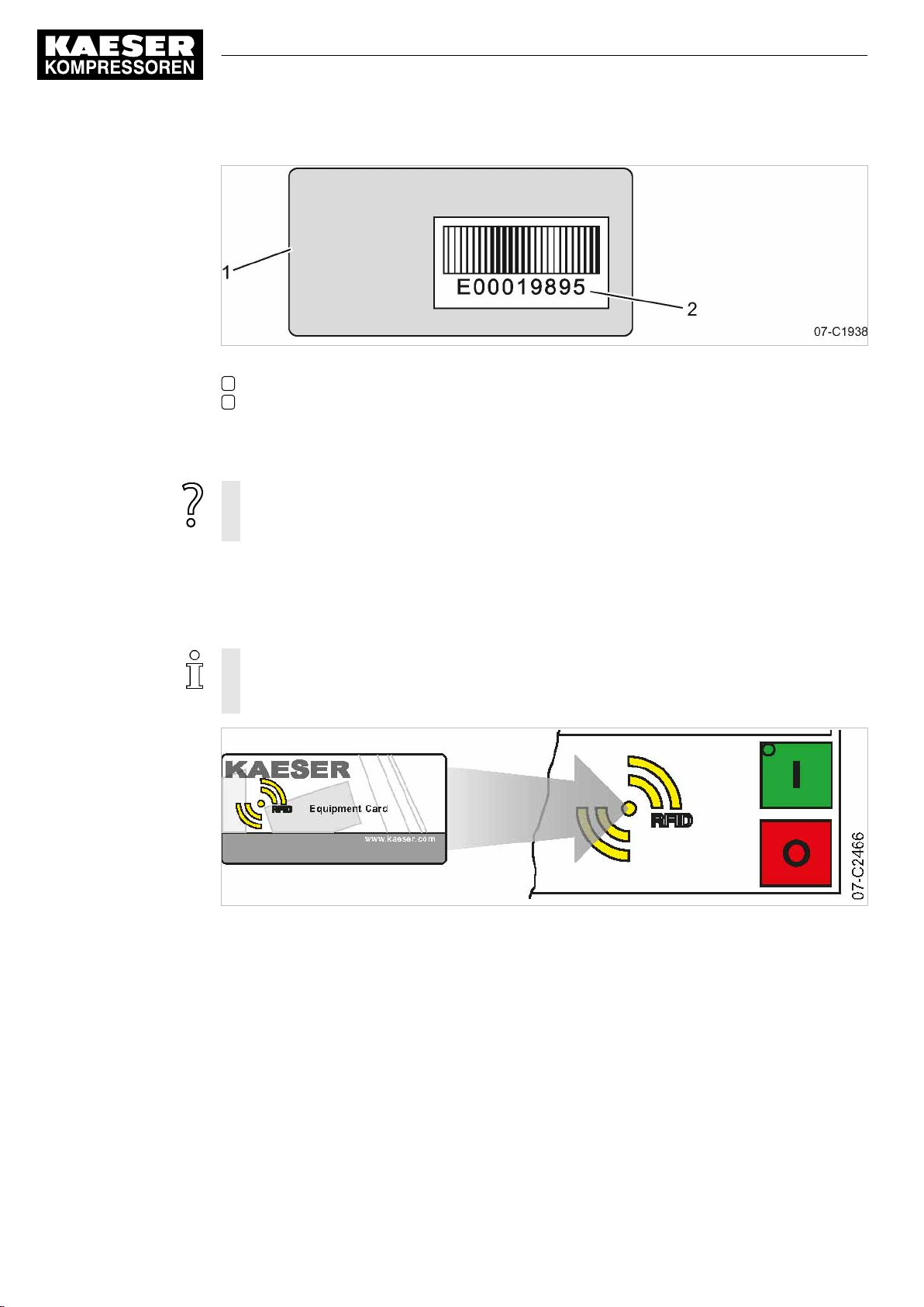
8 Initial Start-up
8.2 Configuring the controller
Fig. 11 Back of the KAESER Equipment Card
1 Back of the KAESER Equipment Card
2 Number of the KAESER Equipment Card
1. Note the user name (= number of the KAESER Equipment Card).
2. Keep the note at a secure location.
If your KAESER Equipment Card gets damaged or can no longer be found?
➤ If you know your user name and password, you can manually log on to
SIGMA CONTROL 2 (see chapter 8.2.5).
8.2.4 User log-in with KAESER Equipment Card
Use the KAESER Equipment Card to quickly and easily check the advanced access rights to the
SIGMA CONTROL 2 controller.
Advanced access rights let you:
■ Read additional data
■ Change other settings
Fig. 12 User log-in with KAESER Equipment Card
52
User Manual Controller
SIGMA CONTROL 2 SCREW FLUID ≥4.0.X No.: 9_9450 07 USE
Page 63

8 Initial Start-up
8.2 Configuring the controller
1. Hold the KAESER Equipment Card in front of the RFID reader.
Your user name and access level will be displayed.
8 8 p s i 0 8 : 1 5 A M 1 7 6 ° F
Log-in successful
Button to change password
__________________________________
Name: E00019895
Level: 2
2. Press «Enter» to confirm the access right.
The access right is confirmed.
The KAESER Equipment Card is damaged or lost?
➤ Manually enter the user name and password, see chapter 8.2.6.
Menu
Prompt, whether the password is to be changed
8.2.5 Generating a password
In the event that your KAESER Equipment Card is damaged or lost, you must manually log on to
SIGMA CONTROL 2. A password is also required to use KAESER CONNECT to log on at
SIGMA CONTROL 2 (see chapter 8.3).
Prerequisite for this is that you know your
■ Name
■ Password
You have noted your user name and stored it at a suitable location (see chapter 8.2.3). You now
generate a password at the SIGMA CONTROL 2. Note this generated password as well, and store
it in a suitable location. If your KAESER Equipment Card is damaged or lost, the card won't be nec‐
essary to manually log on to SIGMA CONTROL 2 when you have these two pieces of information.
Precondition Any menu is displayed
No.: 9_9450 07 USE
Fig. 13 User log-in with KAESER Equipment Card
User Manual Controller
SIGMA CONTROL 2 SCREW FLUID ≥4.0.X
53
Page 64
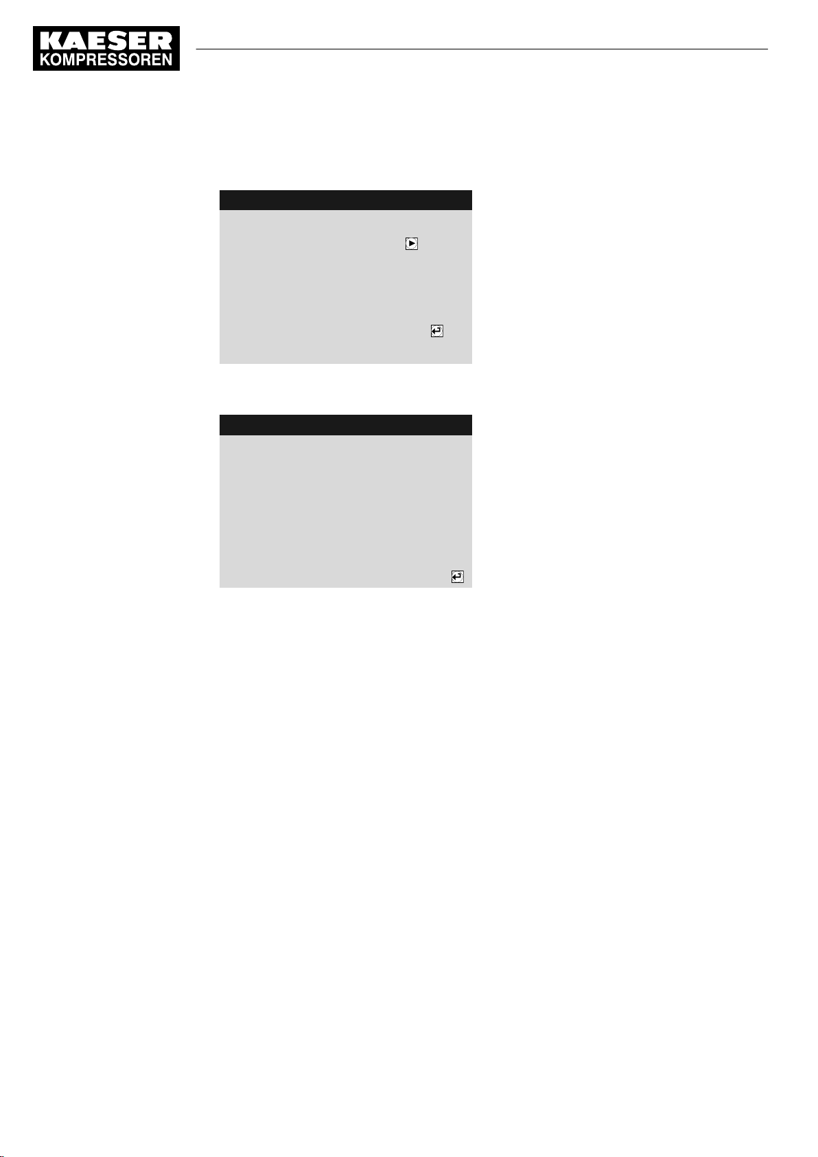
8 Initial Start-up
8.2 Configuring the controller
1. Hold the KAESER Equipment Card in front of the controller’s RFID reader.
Users are always logged on with password access level 2.
8 8 p s i 0 8 : 1 5 A M 1 7 6 ° F
Log-in successful
Button to change password
__________________________________
Name: E00019895
Level: 2
2. Press the «Right» key within five seconds.
The new
Password
8 8 p s i 0 8 : 1 5 A M 1 7 6 ° F
Password changed
__________________________________
Please take note of your new
password:
xFNDQRCnDn
is displayed.
Menu
Prompt, whether the password is to be changed
Menu
New password
3. Note the new password.
4. Store the password at a suitable location, if it should become necessary to manually log-on
without KAESER Equipment Card.
5. Press «Enter».
The setting is applied.
8.2.6 Manual user log-in
In the event that your KAESER Equipment Card is damaged or lost, you can manually log on to
SIGMA CONTROL 2.
Precondition The user name (see chapter 8.2.3) and password (see chapter 8.2.5) are known.
The operating mode is displayed.
1. Open the 7
2. Use «Up» or «Down» to select the
3. Press «Enter».
The setting mode is active.
A column with alphanumeric characters is displayed.
The selected character flashes.
User
menu.
Name
line.
54
User Manual Controller
SIGMA CONTROL 2 SCREW FLUID ≥4.0.X No.: 9_9450 07 USE
Page 65
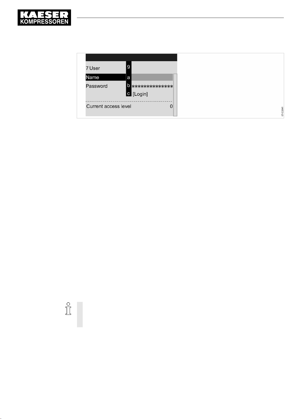
8 Initial Start-up
8.2 Configuring the controller
Fig. 14 Manual user log-in
4. Select the required character with the «Up» or «Down» keys.
5. Press the «Right» key.
The cursor jumps to the next position of the user name.
6. Enter the remaining characters of the user name in the same manner.
7. Press «Enter».
The user name is entered.
8. Use «Up» or «Down» to select the
9. Press «Enter».
Enter the remaining letters and digits of the password in the same manner.
The password is case sensitive!
10. Press «Enter».
The password is entered.
11. Use «Up» or «Down» to select the
12. Press «Enter».
Current access level: 2
is displayed.
Password
[Login]
line.
line.
Result You are now logged on to SIGMA CONTROL 2 with password access level 2, having manually in‐
put your user name and the password.
8.2.7 Checking and setting time and date
Precondition Password access level 2 is activated.
Checking and setting time
➤ When operating the machine with a timer program, check the time settings at least once
a year.
➤ You can automatically synchronize date and time using a time server. Manual setting of
the time is no longer required in this case. See chapter 8.2.15.
1. Open the 5.1
2. Use the «Up» or «Down» keys to select the
<Configuration – General>
menu.
Date/time
line.
No.: 9_9450 07 USE
User Manual Controller
SIGMA CONTROL 2 SCREW FLUID ≥4.0.X
55
Page 66

8 Initial Start-up
8.2 Configuring the controller
3. Press the «DOWN» key.
8 8 p s i 0 8 : 1 5 A M 1 7 6 ° F
5.1 General
▶1 System information
·········
Model: XXXXXX
·········
Date/time
04/13/16 08:15:37AM
4. Press the «Right» key.
5. Press «Enter».
The display for hours
00:00:00
flashes.
6. Use «Up» or «Down» to set the hours.
7. Press the «Right» key.
The display for minutes
00:00:00
flashes.
8. Use «Up» or «Down» to set the minutes.
9. Press the «Right» key.
The display for seconds
00:00:00
flashes.
10. Use «Up» or «Down» to set the seconds.
11. Press «Enter» to accept all settings.
The setting is applied.
12. Press «Escape» repeatedly to return to the main menu.
Menu
Set machine type (SC2 FLUID)
Date and time
Checking and setting the date
Precondition Password access level 2 is activated.
1. Open the 5.1
<Configuration – General>
2. Use the «Up» or «Down» keys to select the
3. Press the «DOWN» key.
8 8 p s i 0 8 : 1 5 A M 1 7 6 ° F
5.1 General
▶1 System information
·········
Model: XXXXXX
·········
Date/time
04/13/16 08:15:37AM
4. Press «Enter».
The display for days
00.00.00
flashes.
5. Use «Up» or «Down» to set the day.
6. Press the «Right» key.
The display for months
00.00.00
flashes.
menu.
Date/time
line.
Menu
Set machine type (SC2 FLUID)
Date and time
56
User Manual Controller
SIGMA CONTROL 2 SCREW FLUID ≥4.0.X No.: 9_9450 07 USE
Page 67

8 Initial Start-up
8.2 Configuring the controller
7. Use «Up» or «Down» to set the month.
8. Press the «Right» key.
The display for years
9. Use the «Up» or «Down» keys to set the years.
10. Press «Enter».
The setting is applied.
11. Press «Escape» repeatedly to return to the main menu.
8.2.8 Set the time zone
Set the time zone for the SIGMA CONTROL 2 to ensure the timely automatic conversion from win‐
ter time (standard time) to daylight savings time, for example.
Precondition Password access level 2 is activated.
00.00.00
flashes.
1. Open the 5.1
2. Use the «Up» or «Down» keys to select the
3. Press «Down» twice.
8 8 p s i 0 8 : 1 5 A M 1 7 6 ° F
5.1 General
Model: XXXXXX
·········
Date/time
04/13/16 08:15:37AM
US/Central
·········
4. Press «Enter».
The time zone display flashes.
5. Use «Up» or «Down» to set the time zone.
6. Press «Enter».
The setting is applied.
7. Press «Escape» repeatedly to leave this menu.
<Configuration – General>
8.2.9 Setting display formats
menu.
Date/time
line.
Menu
Set machine type (SC2 FLUID)
Time zone
No.: 9_9450 07 USE
When setting the language, the system automatically sets the units and the time and date formats.
You can manually change these settings.
Setting the date format
Select your preferred format:
Format Example
DD.MM.YY 30.07.16
YY-MM-DD 16–07–30
MM/DD/YY 07/30/16
Tab. 45 Date formats
User Manual Controller
SIGMA CONTROL 2 SCREW FLUID ≥4.0.X
57
Page 68
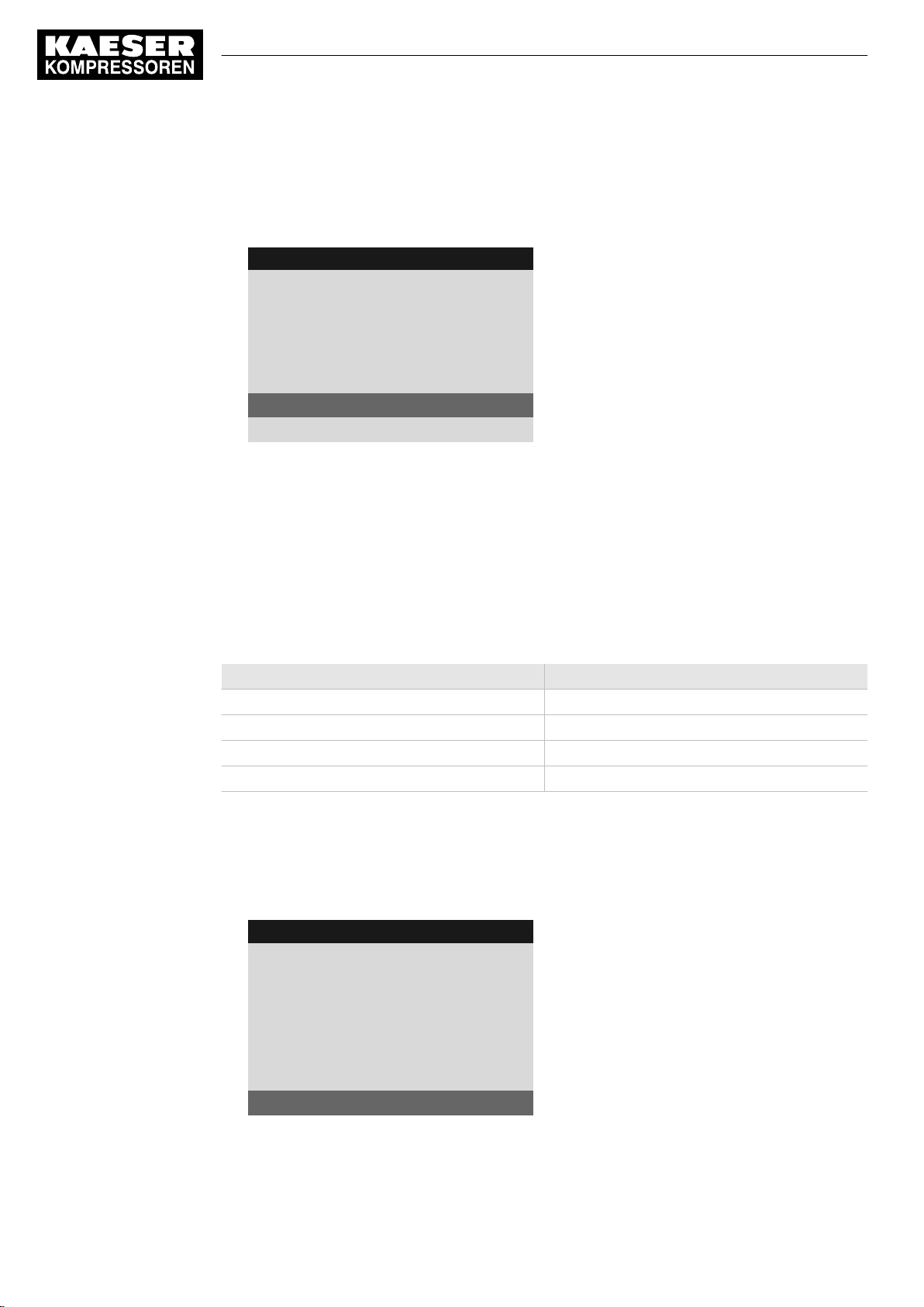
8 Initial Start-up
8.2 Configuring the controller
Precondition Password access level 2 is activated.
1. Open the 5.1
2. Use the «Up» or «Down» keys to select the
<Configuration – General>
menu.
Date format
8 8 p s i 0 8 : 1 5 A M 1 7 6 ° F
5.1 General
US/Central
·········
▶2 Time server
·········
Date format MM/DD/YY
Time format hh:mm:ssAM/PM
Menu
Date format
3. Press «Enter».
The
MM/DD/YY
display flashes.
4. Use the «Up» or «Down» keys to set the date format.
5. Press «Enter».
The setting is applied.
6. Press «Escape» repeatedly to leave this menu.
Setting the time format
Select your preferred format for the time display:
line.
Format Example
hh:mm:ss 13:33:45
hh:mm 13:33
hh:mm:ssAM/PM 01:33:45PM
hh:mmAM/PM 01:33PM
Tab. 46 Time formats
Precondition Password access level 2 is activated.
1. Open the 5.1
<Configuration – General>
2. Use the «Up» or «Down» keys to select the
8 8 p s i 0 8 : 1 5 A M 1 7 6 ° F
5.1 General
US/Central
·········
▶2 Time server
·········
Date format MM/DD/YY
Time format hh:mm:ssAM/PM
menu.
Time format
Menu
Time format
line.
58
3. Press «Enter».
The
hh:mm:ssAM/PM
User Manual Controller
SIGMA CONTROL 2 SCREW FLUID ≥4.0.X No.: 9_9450 07 USE
indication flashes.
Page 69
8 Initial Start-up
8.2 Configuring the controller
4. Use the «Up» or «Down» keys to set the time format.
5. Press «Enter».
The setting is applied.
6. Press «Escape» repeatedly to leave this menu.
Setting the pressure display units
Select your preferred display of the pressure unit:
Format Example
bar 5.5bar
hPa 5523hPa
MPa 0.55MPa
psi 80psi
at 5.6at
Tab. 47 Units of pressure
Precondition Password access level 2 is activated.
1. Open the 5.1
<Configuration – General>
2. Use the «Up» or «Down» keys to select the
8 8 p s i 0 8 : 1 5 A M 1 7 6 ° F
5.1 General
Time
format hh:mm:ssAM/PM
·········
Pressure unit psi
Temperature unit °F
·········
Display lighting
3. Press «Enter».
The display for the set unit flashes.
4. Use the «Up» or «Down» keys to set the unit.
5. Press «Enter».
The setting is applied.
6. Press «Escape» repeatedly to leave this menu.
menu.
Pressure unit
Menu
Unit of pressure
Unit of temperature
line.
No.: 9_9450 07 USE
Setting the temperature display units
Select your preferred display of the temperature unit:
Format Example
°C 46°C
K 319K
°F 114°F
Tab. 48 Units of temperature
User Manual Controller
SIGMA CONTROL 2 SCREW FLUID ≥4.0.X
59
Page 70

8 Initial Start-up
8.2 Configuring the controller
Precondition Password access level 2 is activated.
1. Open the 5.1
2. Use the «Up» or «Down» keys to select the
8 8 p s i 0 8 : 1 5 A M 1 7 6 ° F
5.1 General
Time
format hh:mm:ssAM/PM
·········
Pressure unit psi
Temperature unit °F
·········
Display lighting
3. Press «Enter».
The display for the set unit flashes.
4. Use the «Up» or «Down» keys to set the unit.
5. Press «Enter».
The setting is applied.
6. Press «Escape» repeatedly to leave this menu.
<Configuration – General >
8.2.10 Setting the display illumination
menu.
Temperature unit
Menu
Unit of pressure
Unit of temperature
line.
Select your personal mode for the display illumination:
Mode 1 2 3
Indication
Function The illumination extin‐
Tab. 49 Display illumination
Precondition Access level 2 is activated.
1. Open the 5.1
2. Use the «Up» or «Down» keys to select the
3. Press the «DOWN» key.
The
Mode
8 8 p s i 0 8 : 1 5 A M 1 7 6 ° F
5.1 General
·········
Pressure unit psi
Temperature unit °F
·········
Display lighting
Mode: auto. ¦ Timeout: 1min
<Configuration – General >
line is displayed.
automatic on off
Permanent setting
guishes after the
out
has elapsed.
time-
menu.
Illumination "on"
Display lighting
Menu
Active line
line.
Permanent setting
Illumination "off"
60
User Manual Controller
SIGMA CONTROL 2 SCREW FLUID ≥4.0.X No.: 9_9450 07 USE
Page 71

8 Initial Start-up
8.2 Configuring the controller
4. Press «Enter».
The display for the set mode flashes.
5. Use the «Up» or «Down» keys to set the
6. Press «Enter».
The setting is applied.
7. Press the «Right» key.
8. Set the value for the
9. Press «Enter».
10. Press «Escape» repeatedly to leave this menu.
Result The display illumination is set for automatic operation with deactivation following one minute with‐
out user intervention.
Timeout
in the same manner, e.g. 1 min.
8.2.11 Setting the contrast and the brightness
The display settings for contrast and brightness are set to the highest possible values by default.
Change the settings if adverse lighting conditions make it difficult to read the displayed information.
auto.
mode.
Precondition The operating mode is displayed.
1. Press and hold the «Information» key.
2. Use «Up» or «Down» to adjust the contrast.
3. Use «Left» or «Right» to adjust the brightness.
Result The settings for contrast and brightness have been adjusted.
8.2.12 Activating the remote control
The «Remote control» key on the operating panel of the SIGMA CONTROL 2 can be activated or
deactivated. Various menus offer check boxes for this setting.
Precondition Password access level 2 is activated.
The operating mode is displayed.
1. Open the 8
2. Use «Up» or «Down» to select the
3. Press «Enter».
The check box
8 8 p s i 0 8 : 1 5 A M 1 7 6 ° F
8 Communication
▶1 Ethernet/SIGMA NETWORK
▶2 Com-Module
Key remote ☐
Communication
Key remote
menu.
Key remote
flashes.
line.
Menu
Active line with deactivated check box
No.: 9_9450 07 USE
User Manual Controller
SIGMA CONTROL 2 SCREW FLUID ≥4.0.X
61
Page 72

8 Initial Start-up
8.2 Configuring the controller
4. Press the «Up» key.
The check box
8 8 p s i 0 8 : 1 5 A M 1 7 6 ° F
8 Communication
▶1 Ethernet/SIGMA NETWORK
▶2 Com-Module
Key remote ☑
5. Press «Enter».
The «Remote control» key is activated.
6. Press «Escape» repeatedly to leave this menu.
Key remote
is activated.
Menu
Active line with activated check box
Proceed in the same manner to deactivate the «Remote control» key.
7. Press the «Remote control» key on the operating panel of SIGMA CONTROL 2.
Result SIGMA CONTROL 2 Remote control is activated.
8.2.13 IP configuration
For the SIGMA CONTROL 2 to be connected to the network, you must set the IP configuration (for
KAESER CONNECT for example).
If you use SIGMA CONTROL 2 as the master control of two machines, you set other network
parameters in the
The network parameters for the IP configuration must be specified manually. You cannot use
DHCP for an automatic IP configuration.
Precondition Password access level 2 is activated.
The network parameters are known. Request the required information from your IT department.
1. SIGMA CONTROL 2 Connect to the network using an Ethernet cable.
2. Select the 8.1.1
3. Use «Up» or «Down» to select the
8 8 p s i 0 8 : 1 5 A M 1 7 6 ° F
8.1.1 IP configuration
IP address 169.254.100.101
Subnet mask 255.255.000.000
Gateway 169.254.100.97
DNS Server 1 169,254,100.97
DNS Server 2 169,254,100.97
Restart network ☐
IP configuration
<Communication – Ethernet/SIGMA NETWORK – IP configuration>
menu (see chapter 8.10.4).
IP address
line.
Menu
Active line, factory setting
menu.
62
4. Press «Enter» to switch into setting mode.
The first group of numbers of the
User Manual Controller
SIGMA CONTROL 2 SCREW FLUID ≥4.0.X No.: 9_9450 07 USE
IP address
flashes
169.254.100.101
.
Page 73
8 Initial Start-up
8.2 Configuring the controller
5. Use «Up» or «Down» to set the first group of numbers of the
6. Press the «Right» key.
The SECOND group of numbers of the
7. Use «Up» or «Down» to set the second, third and fourth group of numbers of the
The
IP address
8. Press «Enter» to accept the setting.
The setting is applied.
9. Press «Down».
The
Subnet mask
10. Set the remaining network parameters as described above:
Parameters Setting value Meaning
IP address IP address of the interface X1 Ethernet
Subnet mask Subnet mask of the network
Gateway Gateway address of the network
DNS Server 1 DNS server 1 address
DNS Server 2 DNS server 2 address
Restart network – Activate the changed network parameters
Tab. 50 Network parameters
is correctly set.
line is displayed.
IP address
flashes
IP address
.
192.168.100.101
.
IP address
.
11. Use the «Up» or «Down» keys to select the
8 8 p s i 0 8 : 1 5 A M 1 7 6 ° F
8.1.1 IP configuration
IP address 192.168.001.010
Subnet mask 255.255.255.000
Gateway 192.168.001.001
DNS Server 1 008.008.008.008
DNS Server 2 008.008.004.004
Restart network ☐
12. Press «Enter».
The check box
13. Press «Up» key.
The check box is activated.
14. Press «Enter».
Result The network is restarted.
The set network parameters are active.
Restart network
8.2.14 Setting the e-mail function
will flash.
Restart network
Menu
Example address
Example address
Example address
Example address
Example address
Active line
line.
No.: 9_9450 07 USE
SIGMA CONTROL 2 uses e-mail to send information (messages) to an e-mail address.
For this purpose, an Ethernet connection with an SMTP server is required.
User Manual Controller
SIGMA CONTROL 2 SCREW FLUID ≥4.0.X
63
Page 74
8 Initial Start-up
8.2 Configuring the controller
Setting e-mail parameters
Precondition Password access level 2 is activated.
IP configuration is set; see chapter 8.2.13
An SMTP server is active in the network.
The e-mail parameters are known. Request the required information from your IT department.
1. Open the 8.1.3
2. Use the «Up» or «Down» keys to select the
8 8 p s i 0 8 : 1 5 A M 1 7 6 ° F
8.1.3 E-mail
active: ☐
Compressor number: 1
Language: English US
Repeat cut-off time: 5min
__________________________________
Sender address:
3. Press «Enter».
The check box
4. Press «Up» key.
The check box is deactivated.
5. Press «Enter».
The e-mail function is deactivated.
6. Set the e-mail parameters as described above:
Parameters Setting
Compressor
number:
Language: Use this field to define the language for the message texts. This setting
Repeat cut-off
time:
Sender address: Enter the e-mail address of the sender in this field.
Sender name: Enter the name of the sender in this field.
Contact
telephone:
Receiver
address:
SMTP Server: IP address of the SMTP server receiving and forwarding the e-mails.
User name: Log-in user name for logging on to the SMTP server.
Password Log-in password for logging on to the SMTP server.
<Communication – Ethernet/SIGMA NETWORK – E-mail>
active:
line.
Menu
Activating/deactivating the e-mail function
Setting the language
active:
will flash.
Meaning
value
This field displays the machine number that appears as the sender of
e-mails. The recipient is thus able to recognize the different machines
sending mails.
in independent from the language setting in SIGMA CONTROL 2 (see
chapter 8.2.2).
In this field, enter the time in minutes (repeat block time) that the sys‐
tem must wait in order not send multiple recurring messages in short
time intervals.
In this field, enter a telephone number under which the system operator
can be reached. This telephone number is sent with each e-mail.
The e-mail address of the recipient.
menu.
64
User Manual Controller
SIGMA CONTROL 2 SCREW FLUID ≥4.0.X No.: 9_9450 07 USE
Page 75

8 Initial Start-up
8.2 Configuring the controller
Parameters Setting
value
Port Port address of the SMTP server.
Timeout In this field, enter the seconds for SIGMA CONTROL 2 to wait for a re‐
Resend after: In this field enter, the time in seconds for the system to wait after a
Tab. 51 E-mail parameters
7. Activating the e-mail function: Activate the
8. Press «Esc» repeatedly to leave this menu.
Result The e-mail parameters are set and the e-mail function is activated.
Meaning
ply by the SMTP server before e-mail sending is cancelled.
failed e-mail sending operation before it again attempts to send the
mail.
active:
8.2.15 Configuring the time server
If SIGMA CONTROL 2 is connected to the network, you can set the access to an SNTP server
available in the Internet or a local Intranet. SIGMA CONTROL 2 then automatically imports the
date and time settings and ensures continuous synchronization of the internal clock with the exter‐
nal time server.
Precondition Password access level 2 is activated.
IP configuration is set; see chapter 8.2.13.
The time server's IP address is known. Request the required information from your IT department.
check box as described above.
1. Open the 5.1.2
2. Use the «Up» or «Down» keys to select the
8 8 p s i 0 8 : 1 5 A M 1 7 6 ° F
5.1.2 Time server
active: ☐
IP address 192.053.103.103
3. Press «Enter».
The first group of numbers of the
4. Use «Up» or «Down» to set the first group of numbers of the
5. Press the «Right» key.
The second group of numbers of the
6. Use «Up» or «Down» to set the second, third and fourth group of numbers of the
The
IP address
7. Press «Enter» to accept the setting.
The setting is applied.
8. Use «Up» or «Down» to select the
<Configuration – General – Time server>
is correctly set.
IP address
IP address
active:
line.
IP address
Menu
Activating/deactivating the time server function
Example address, time server
flashes
line.
192.053.103.103
flashes
menu.
.
IP address
192.053.103.103
.
.
IP address
.
No.: 9_9450 07 USE
User Manual Controller
SIGMA CONTROL 2 SCREW FLUID ≥4.0.X
65
Page 76

8 Initial Start-up
8.3 Using KAESER CONNECT
9. Press «Enter».
The check box
10. Press «Up» key.
The check box is activated.
8 8 p s i 0 8 : 1 5 A M 1 7 6 ° F
5.1.2 Time server
active: ☑
IP address 192.053.103.103
11. Press «Enter».
12. Press «Escape» repeatedly to return to the main menu.
active:
will flash.
Menu
The time server function is activated
Example address, time server
Result Access to the selected time server is active.
The internal clock of SIGMA CONTROL 2 is permanently synchronized.
8.3 Using KAESER CONNECT
Using an Internet-capable device with web browser, you can use KAESER CONNECT to remotely
display these SIGMA CONTROL 2 menus:
■ System status
■ Graphs
■ Messages
■ I/O display
■ User management
■ Settings
■ Backup
■ Data recording
Thus, KAESER CONNECT provides an excellent option for an easy and quick check of the econo‐
my and energy efficiency of your machines.
The following functions are not available with KAESER CONNECT:
■ Remotely starting the machine
■ Remotely setting parameters
66
For KAESER CONNECT to be able to use the Internet-capable device, it must be registered
in the same network as SIGMA CONTROL 2.
To be able to use KAESER CONNECT, the browser installed on the Internet-capable device
must be able to display HTML5 content. For security reasons, we strongly recommend to use
only up-to-date browser versions.
User Manual Controller
SIGMA CONTROL 2 SCREW FLUID ≥4.0.X No.: 9_9450 07 USE
Page 77
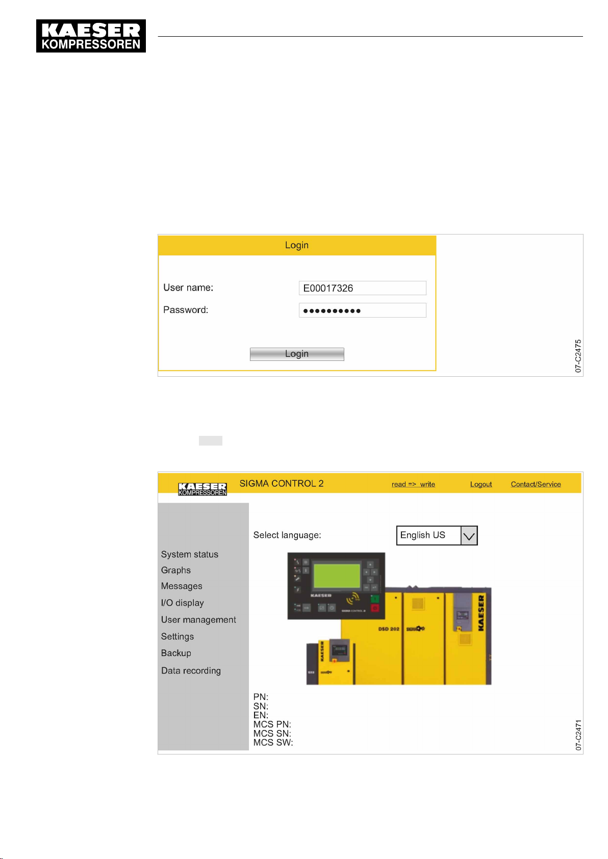
8 Initial Start-up
8.3 Using KAESER CONNECT
8.3.1 Open KAESER CONNECT
Precondition The user name (see chapter 8.2.3) and password (see chapter 8.2.5) are known.
The IP address of your controller is known, see chapters 8.2.13 and 8.10.4.
1. Use an Ethernet cable to connect SIGMA CONTROL 2 to the Internet-capable device or net‐
work.
2. In the web browser, enter the controller's IP address.
The Login window is displayed.
Fig. 15 Login window
3. Enter your user name in the
4. Enter your password in the
5. Click Login.
KAESER CONNECT for SIGMA CONTROL 2 is displayed.
User name:
Password:
field.
field.
No.: 9_9450 07 USE
Fig. 16 KAESER CONNECT for SIGMA CONTROL 2
User Manual Controller
SIGMA CONTROL 2 SCREW FLUID ≥4.0.X
67
Page 78
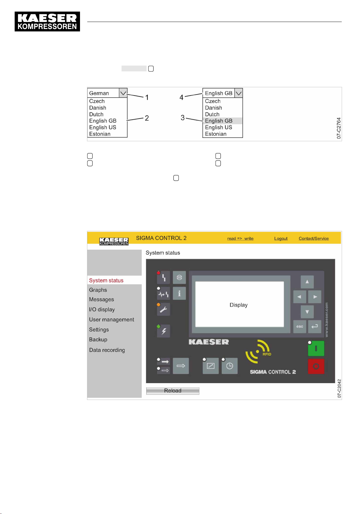
8 Initial Start-up
8.3 Using KAESER CONNECT
6. Click the arrow key 1 to open Select language:.
The
Select language:
Fig. 17 Select language: window
1 «Arrow key» Select language:
2 Select language: window
7. Select the required language 3 .
Result KAESER CONNECT is displayed in the selected language.
window is displayed.
3 Select a language
4 Selected language
8.3.2 System status menu
Precondition KAESER CONNECT for SIGMA CONTROL 2 is displayed.
68
Fig. 18
System status
1. Click the
The
User Manual Controller
SIGMA CONTROL 2 SCREW FLUID ≥4.0.X No.: 9_9450 07 USE
menu
System status
System status
menu element.
menu is displayed
Page 79
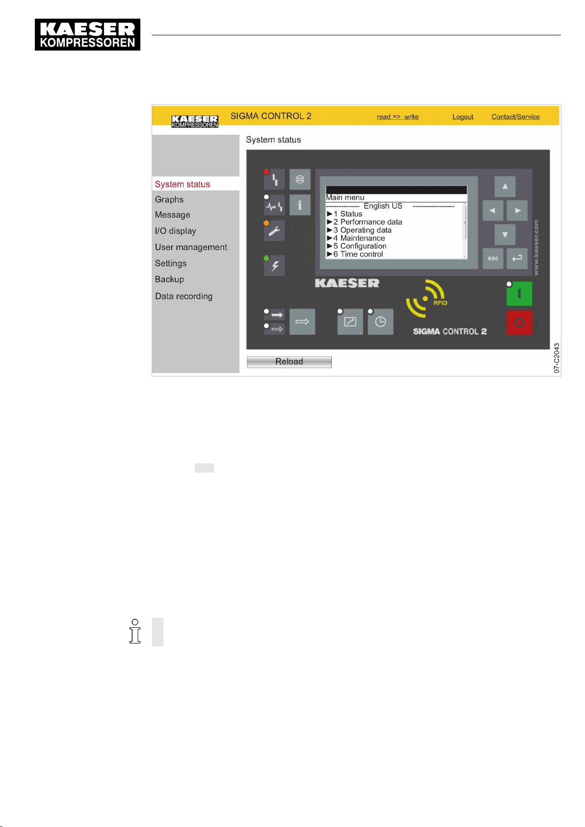
8 Initial Start-up
8.3 Using KAESER CONNECT
Fig. 19 Main menu
2. Click in the SIGMA CONTROL 2 display.
The Main menu is displayed.
3. Click the numbered lines.
The system displays the corresponding sub-menus.
4. Press ESC repeatedly to leave this menu.
8.3.3 Graphs menu
When starting the
20 minutes are displayed in a graph. The system updates the graph every ten seconds whilst the
current time is displayed.
If an SD card is provided in the X5 SD card slot, you can retrieve and display the automaticallyrecorded machine data for any time in the past.
Moving the mouse pointer across the graph calls up a ruler. The time selected with the ruler and
the associated values are displayed in the legend above the graph. When the ruler is hidden, the
time and associated values are displayed at the right edge of the graph.
The graph content depends on the machine type.
The
Speed
Precondition KAESER CONNECT for SIGMA CONTROL 2 is displayed.
Graphs
display is implemented only for machines with frequency converter.
menu, the recorded data from the last 60 minutes are loaded. The last
No.: 9_9450 07 USE
1. Click the
User Manual Controller
SIGMA CONTROL 2 SCREW FLUID ≥4.0.X
Graphs
menu element.
69
Page 80
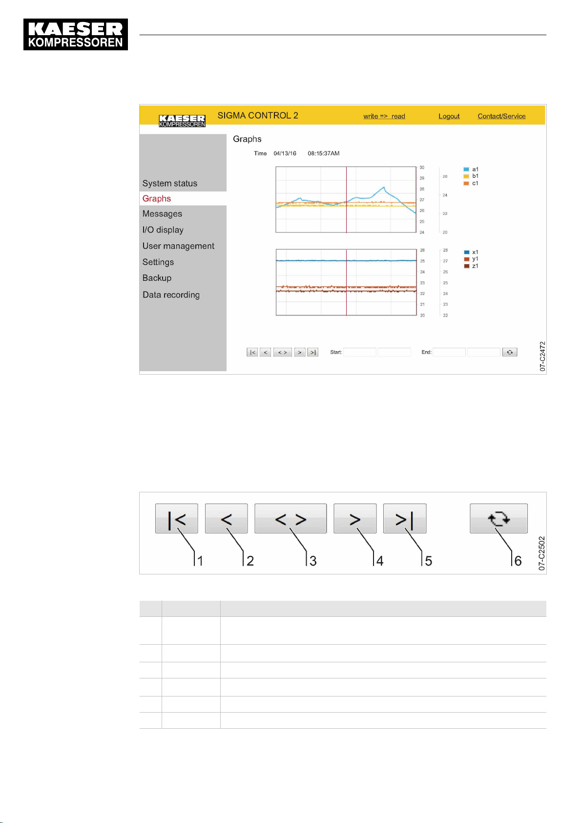
8 Initial Start-up
8.3 Using KAESER CONNECT
Fig. 20
8.3.3.1 Zoom function
Fig. 21 Arrow keys
Graphs
2. Check the displayed data.
Use the Zoom function to enlarge significant curve developments:
Highlight a specific area within the graph by drawing a rectangle with the mouse pointer pressed.
The selected area will be enlarged as soon as the mouse pointer is released.
(illustration similar)
Item Description Function
1 «Start» Display the oldest data in the cache memory or load the data from the previ‐
2 «Scroll left»
ous 20 minutes from the SD card
Shift the display area by 1/3 to the left
70
3 «Zoom-out» Time range is enlarged
4 «Scroll right»
5 «End» Display of newest data
6 «Refresh» Load and display the entered machine data from start time to end time
Tab. 52 Arrow key functions
User Manual Controller
SIGMA CONTROL 2 SCREW FLUID ≥4.0.X No.: 9_9450 07 USE
Shift the display area by 1/3 to the right
Page 81

8 Initial Start-up
8.3 Using KAESER CONNECT
1. Click the «Start» 1 arrow key.
The oldest data in the cache memory or the data of the last 20 minutes are loaded form the SD
card and displayed
2. Click the «Scroll right» 4 arrow key.
The display area is shifted to the right by 1/3.
3. With the mouse button pressed, draw a rectangle around the selected area.
4. Release the mouse button.
The selected area is enlarged (zoom-in function).
5. Click the «Zoom-out» 3
The time range is enlarged (zoom-out function).
8.3.3.2 Displaying past machine data
You can display the automatically-recorded machine data for any time in the past.
Precondition An SD card with sufficient free memory is inserted in the X5 SD card slot
The SD card was inserted for the entire operating time of the machine.
The SIGMA CONTROL 2 data recorder function is activated.
arrow key.
1. Enter the date and time for the start time in the required time period in
2. Enter the date and time for the end time in the required time period in
3. Click 6 .
The machine data for the specified time interval are loaded and displayed.
8.3.4 Messages menu
The following messages are shown:
■ Current messages
■ Compressor messages
■ System messages
■ Diagnostic messages
Precondition KAESER CONNECT for SIGMA CONTROL 2 is displayed.
Start:
End:
.
.
No.: 9_9450 07 USE
User Manual Controller
SIGMA CONTROL 2 SCREW FLUID ≥4.0.X
71
Page 82
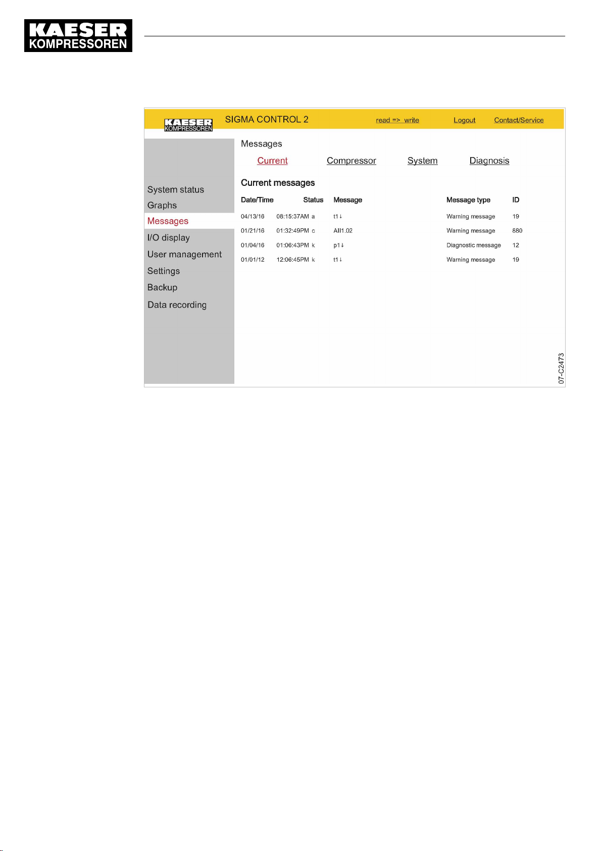
8 Initial Start-up
8.3 Using KAESER CONNECT
Fig. 22
Messages
1. Open the
The
2. Click the required message type.
3. Check messages.
Messages
Messages
menu.
menu is displayed.
8.3.5 I/O display menu
The measured values of the analog inputs and the states of the digital inputs and outputs are dis‐
played in the
IOM module tabs.
Precondition KAESER CONNECT for SIGMA CONTROL 2 is displayed.
I/O display
menu. Depending on the machine options, you may select from further
72
User Manual Controller
SIGMA CONTROL 2 SCREW FLUID ≥4.0.X No.: 9_9450 07 USE
Page 83
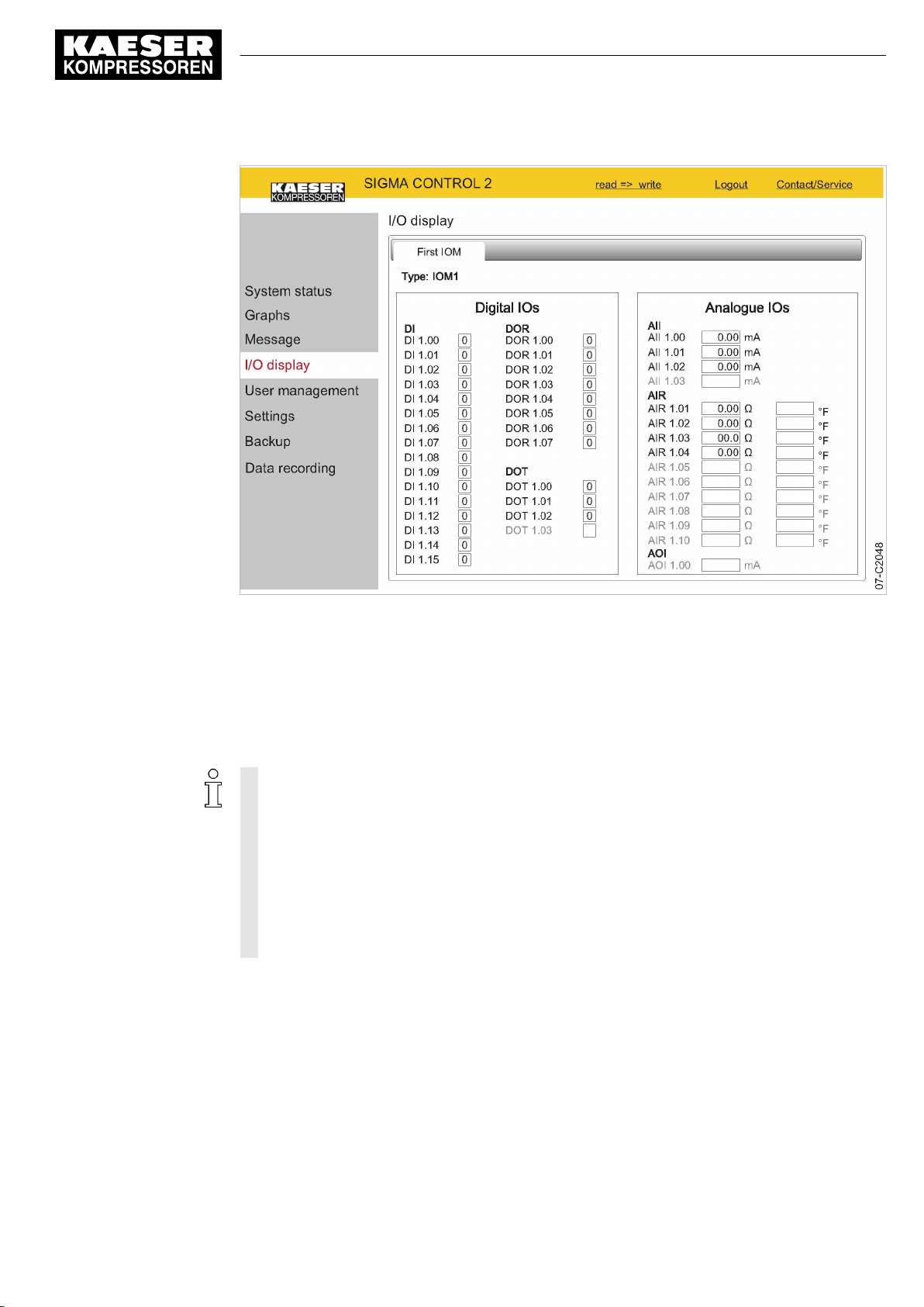
8 Initial Start-up
8.3 Using KAESER CONNECT
Fig. 23
I/O display
➤ Click the
(illustration similar)
I/O display
The current measured data and states of the input/output modules are displayed.
menu element.
8.3.6 User management menu
Use the
Precondition The generated password is available.
KAESER CONNECT for SIGMA CONTROL 2 is displayed.
User management
In order to be able to create user accounts, you must activate the write mode. The system will
prompt you to enter and confirm your user name and your password. Subsequently, the write
mode is activated (see Chapter 8.2.5).
The write mode is granted only to one person at a time.
If a second user attempts to log on in write mode, he will be refused by the system.
The system will return an error message.
String length for personally created user names and passwords:
■ User name: 6 to 16 characters, the second character must not be a number
■ Password: 6 to 16 characters
menu to create additional user accounts for other employees.
No.: 9_9450 07 USE
User Manual Controller
SIGMA CONTROL 2 SCREW FLUID ≥4.0.X
73
Page 84
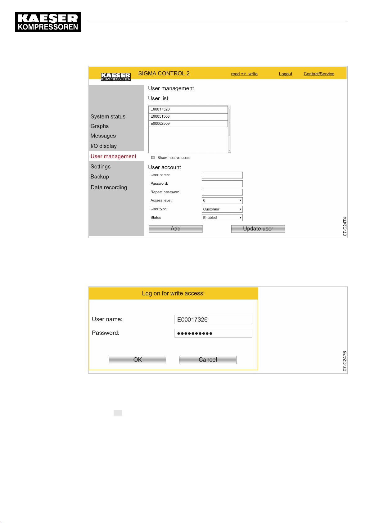
8 Initial Start-up
8.3 Using KAESER CONNECT
Fig. 24
Fig. 25
User management
1. Select the
2. Click
read => write
The
Log on for write access:
Log on for write access:
3. Enter your user name in the
4. Enter your password in the
5. Click OK.
The
User management
menu
User management
to activate the read/write mode.
window
menu is displayed.
menu element.
window is displayed.
User name:
Password:
field.
field.
74
User Manual Controller
SIGMA CONTROL 2 SCREW FLUID ≥4.0.X No.: 9_9450 07 USE
Page 85
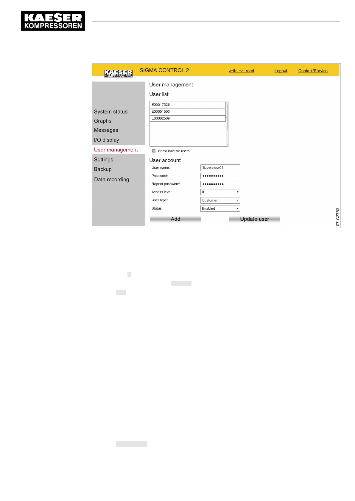
8 Initial Start-up
8.3 Using KAESER CONNECT
Fig. 26
Result A new user account has been created and activated.
Precondition The
User management
6. Enter a new user name in the
7. Enter a new password in the
8. Re-enter the same new password in the
9. Set Level 2 in the
10. Set the
11. Click Add.
The new user name has been added to the user list.
Editing a user account
You can edit existing user accounts:
■ Changing the password
■ Changing the access level
■ Changing the status
Example: Change the password for an existing user account.
User management
Write mode is activated.
menu
Access level:
State:
option in the Enabled field.
menu is displayed.
User name:
Password:
field.
field.
field.
Repeat password:
field.
No.: 9_9450 07 USE
1. Click the required user account in the list.
2. Enter a new password in the
3. Re-enter the same new password in the
4. Click Update user.
User Manual Controller
SIGMA CONTROL 2 SCREW FLUID ≥4.0.X
Password:
field.
Repeat password:
field.
75
Page 86
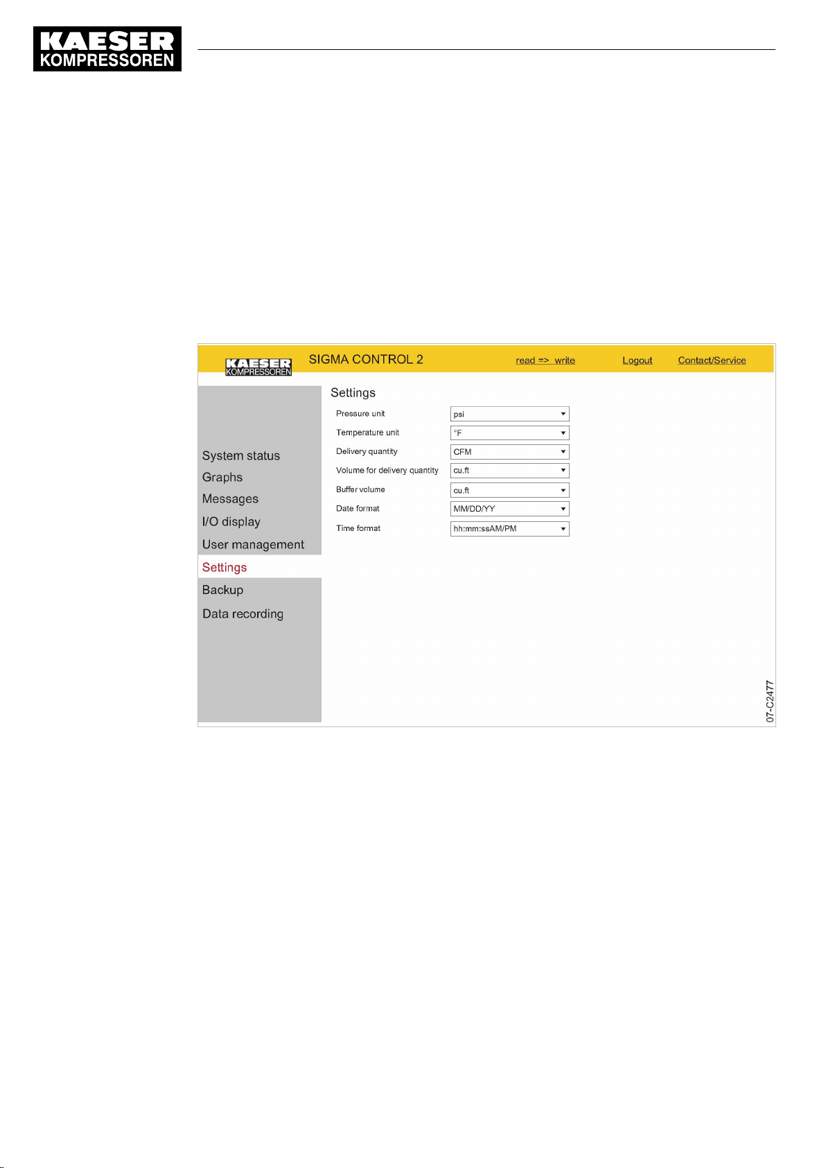
8 Initial Start-up
8.3 Using KAESER CONNECT
Result The password for the existing user account is changed.
8.3.7 Settings
Settings via KAESER CONNECT apply only to your PC and your Browser.
The following settings are available.
■ Units
■ Date format
■ Time format
76
Fig. 27
Precondition KAESER CONNECT for SIGMA CONTROL 2 is displayed.
Settings
Converting units to US values:
1. Select the
2. Click the arrow key for the unit of pressure.
A selection list of units of pressure is displayed.
3. Select the desired unit.
4. Click the arrow key for the unit of temperature.
A selection list of units of temperature is displayed.
5. Select the desired unit.
6. Set additional units and date and time formats.
User Manual Controller
SIGMA CONTROL 2 SCREW FLUID ≥4.0.X No.: 9_9450 07 USE
Settings
menu.
Page 87
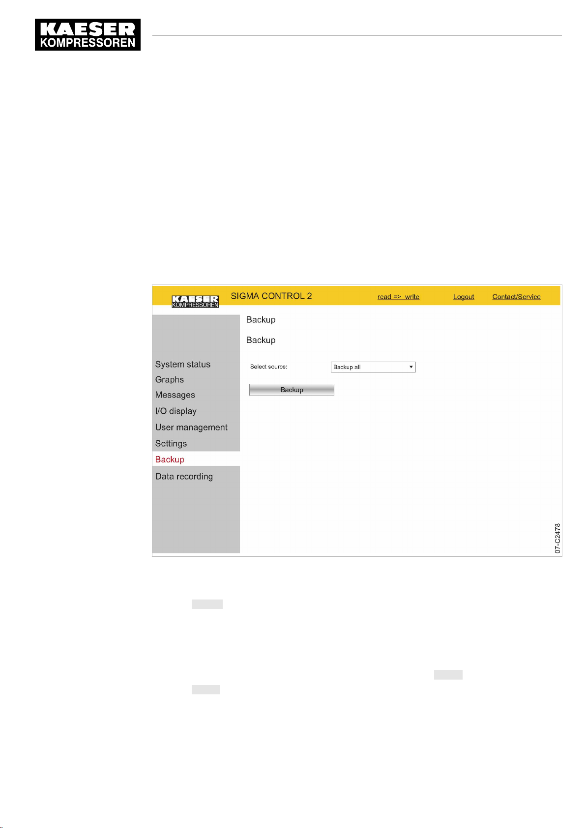
8 Initial Start-up
8.3 Using KAESER CONNECT
8.3.8 Backup menu
The
Backup
device.
The following backup types are available:
■ Backup all
■ Log files
■ Settings
■ User information
Precondition KAESER CONNECT for SIGMA CONTROL 2 is displayed.
menu allows you to download data from SIGMA CONTROL 2 to the Internet-capable
1. Click the
Backup
menu element.
No.: 9_9450 07 USE
Fig. 28
Result The data are downloaded to the Internet-capable device.
Backup
2. Set the required backup type in the
3. Click Backup.
menu
Select source:
8.3.9 Closing KAESER CONNECT
In order to close KAESER CONNECTfor SIGMA CONTROL 2, click Logout in the header.
➤ Click Logout.
The system displays a message confirming the successful logout.
User Manual Controller
SIGMA CONTROL 2 SCREW FLUID ≥4.0.X
option.
77
Page 88
8 Initial Start-up
8.4 Adjusting the pressure parameters of the machine
8.4 Adjusting the pressure parameters of the machine
This section contains instructions for how to display and adjust the pressure parameters of the ma‐
chine.
The section is divided into the following sections:
■ 8.4.1: Displaying pressure parameters
■ 8.4.2: Configuring the pressure parameters
"Display" means that the parameter will only be shown.
"Setting" means that the parameter can also be changed.
Parameters Explanation
pRV Display:
Activating pressure of the safety relief valve on the oil separator tank.
pE Pressure increase.
Setting:
■ pE SP: Switching point for pressure increase; upper safety limit for machine
maximum pressure; in an external LOAD control, this value is used to switch
the machine from LOAD to IDLE in the event of a fault.
■ pE SD: Switching differential of pressure increase.
ΔpFC Limiting value for machines with frequency-controlled drive (SFC).
Setting:
■ dp FC: Limit of the lowest delivery quantity. When the value [switching point
system setpoint pressure +dp FC] is exceeded, the compressor switches from
LOAD to IDLE.
Nominal
pressure
Setpoint
pressure
System
pressure low
Display:
The compressor is designed for this pressure (maximum system pressure set‐
point).
Setpoint pressure can be regulated to two values: pA and pB.
Setting:
■ Switching point pA or control pressure pA in machines with frequency convert‐
er (SFC).
■ Switching point pB or control pressure pB in machines with frequency convert‐
er (SFC).
A warning message is displayed when the limit value for the system pressure is
reached.
78
Setting:
■ SD: Switching differential for system pressure low.
↓: Switching point for system pressure low.
■ Option: Configure the output signal.
Warning message displayed or an additional output signal is sent, e.g., to a
control center.
User Manual Controller
SIGMA CONTROL 2 SCREW FLUID ≥4.0.X No.: 9_9450 07 USE
Page 89
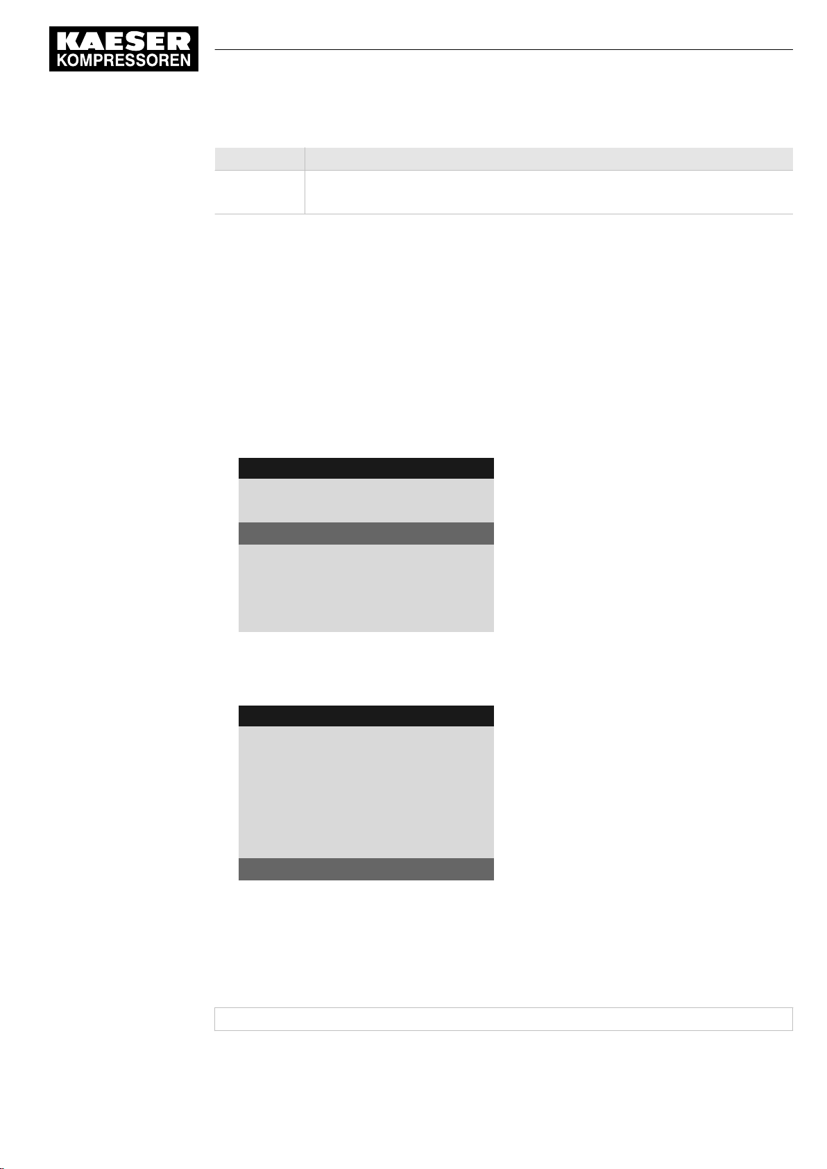
8 Initial Start-up
8.4 Adjusting the pressure parameters of the machine
Parameters Explanation
Cut-in
pressure min
Tab. 53 Compressor pressure parameters
➤ Parameters correspond to the following specifications.
8.4.1 Displaying pressure parameters
Precondition Password access level 2 is activated.
Opening the menu for pressure parameters
Display:
For design reasons, pressure can only be built up above this value.
1. Open the 5.2.2
2. Press «Enter».
The
Pressure settings
8 8 p s i 0 8 : 1 5 A M 1 7 6 ° F
5.2.2 Pressure settings
Setpoint pressure
pA SP: 116psi ¦ SD: −7.3psi
pB SP: 109psi ¦ SD: −5.8 psi
·········
System pressure low ☐
↓ < 72.5psi ¦ SD: 7.2psi
Displaying further parameters
1. Use the «Up» or «Down» keys to select the
8 8 p s i 0 8 : 1 5 A M 1 7 6 ° F
5.2.2 Pressure settings
System pressure low ☐
↓ < 72.5psi ¦ SD: 7.2psi
ta: 600s
DOR1.03 ☐ ¦ Logic: +
__________________________________
Cut-in pressure min : 72.5psi
<Configuration – Pressure control – Pressure settings>
menu is displayed.
Menu
Active line
Cut-in pressure min
Menu
Active line
menu.
line.
No.: 9_9450 07 USE
2. Display further parameters with the «Up» and «Down» keys.
8.4.2 Configuring the pressure parameters
8.4.2.1 Adjusting the system setpoint pressure: pA and pB
The pressure parameters can only be set within certain limits:
Rated machine pressure ≥ SP: pA pB / ≥ Min. cut-in pressure* + switching differential
Tab. 54 Setting limits for the system setpoint pressure (* Cut-in pressure min)
User Manual Controller
SIGMA CONTROL 2 SCREW FLUID ≥4.0.X
79
Page 90

8 Initial Start-up
8.4 Adjusting the pressure parameters of the machine
The machine switches to LOAD under the following condition:
System pressure ≤ SP: pA /pB - switching differential
Tab. 55 Pressure condition for LOAD
The machine switches to IDLE under the following conditions:
System pressure = System setpoint pressure
Tab. 56 Pressure conditions for IDLE
Precondition Password access level 2 is activated.
1. Select the 5.2.2
2. Use «Up» or «Down» to select the
8 8 p s i 0 8 : 1 5 A M 1 7 6 ° F
5.2.2 Pressure settings
·········
Setpoint pressure
pA SP: 116psi ¦ SD: −7.3psi
pB SP: 109psi ¦ SD: −5.8 psi
·········
System pressure low ☐
3. Press «Enter».
The setting mode is active.
4. Use «Up» or «Down» to adjust the
5. Press «Enter» to accept the setting.
The setting is applied.
6. Adjust the SD switching differential in the same way.
7. Adjust the
8. Press «Escape» repeatedly to return to the main menu.
<Configuration – Pressure control – Pressure settings>
pASP
line.
Menu
Active line with current value for system setpoint
pressure pA
pA SP
value.
pB SP
and the SD switching differential in the same manner, if necessary.
menu.
80
Result The settings for the system setpoint pressure pA and pB are adjusted.
8.4.2.2 Adjusting the value for "System pressure low"
If the system pressure falls to the
warning message for the system pressure being too low.
Be generous when setting the time value for the display of the warning message.
If the time interval is set too short, the system will display a warning message despite the machine
delivering compressed air and approaching the preset value for the system setpoint pressure.
The switching differential influences the pressure level at which the message can be acknowledged
or the optionally activated output can switch again:
Message Output
72.5 psi message appears Active
80.0 psi message disappears Inactive
Tab. 57 Example: activated output
User Manual Controller
SIGMA CONTROL 2 SCREW FLUID ≥4.0.X No.: 9_9450 07 USE
System pressure low
value, SIGMA CONTROL 2 will display a
Page 91
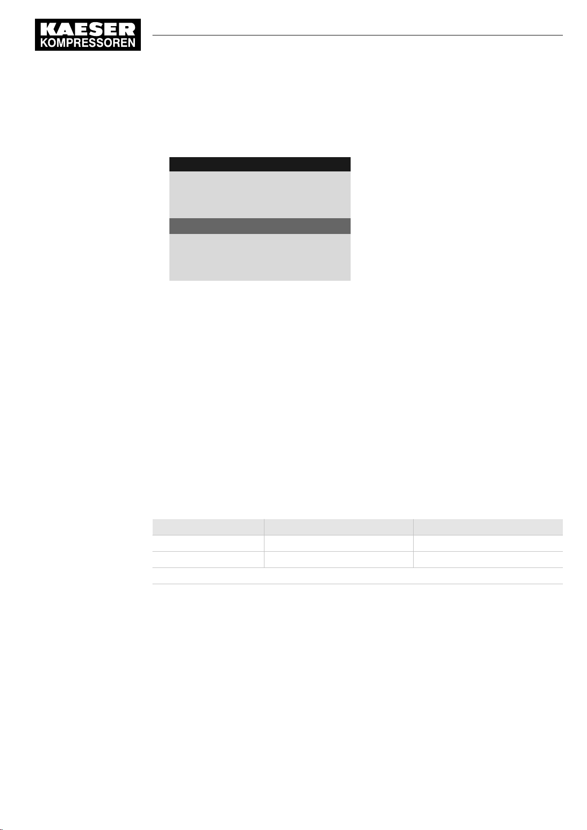
8 Initial Start-up
8.4 Adjusting the pressure parameters of the machine
Precondition Password access level 2 is activated.
1. Select the 5.2.2
2. Use «Up» or «Down» to select the ↓< line.
8 8 p s i 0 8 : 1 5 A M 1 7 6 ° F
5.2.2 Pressure settings
·········
System pressure low ☐
↓ < 72.5psi ¦ SD: 7.2psi
ta: 600s
DOR1.03 ☐ ¦ Logic: +
__________________________________
3. Press «Enter» to switch into setting mode.
The setting mode is active.
4. Use «Up» or «Down» to adjust the value for
5. Press «Enter» to accept the setting.
The setting is applied.
6. Adjust the SD switching differential in the same way, if necessary.
7. Press «Escape» repeatedly to leave this menu.
8.4.2.3 Adjusting the SD switching differential of the pressure increase
<Configuration – Pressure control – Pressure settings>
Menu
Current system pressure low point
System pressure low
menu.
.
The value for pressure rise
controlled. When the system setpoint pressure reaches the value
external control functions incorrectly) the machine switches to IDLE. The warning message
External load signal?
The parameter for
adjust the SD switching differential.
Displaying and adjusting the pressure increase parameters:
Pressure increase Display parameters Setting parameters
Switching point
Switching differential
x = fitted, − = not fitted
Tab. 58 Displaying and adjusting parameters
Precondition Password access level 2 is activated.
1. Select the 5.2.2
pE SP
pE SP
pE SP
serves as a safety limit value when the machine is externally
is displayed.
pressure increase is preset and cannot be changed. You can, however,
SD
<Configuration – Pressure control – Pressure settings>
pE SP
(for example, when the
x –
x x
menu.
No.: 9_9450 07 USE
User Manual Controller
SIGMA CONTROL 2 SCREW FLUID ≥4.0.X
81
Page 92

8 Initial Start-up
8.4 Adjusting the pressure parameters of the machine
2. Use «Up» or «Down» to select the
8 8 p s i 0 8 : 1 5 A M 1 7 6 ° F
5.2.2 Pressure settings
pRV: 232psi
__________________________________
Pressure rise
pE SP: 122psi ¦ SD: −8.7psi
ΔpFC: 2.9psi
·········
3. Press «Enter» to switch into setting mode.
The setting mode is active.
4. Use «UP» or «DOWN» to adjust the required value for SD.
5. Press «Enter» to accept the setting.
The setting is applied.
6. Press «Escape» repeatedly to return to the main menu.
pESP
line.
Menu
Active line
8.4.3 Activating/deactivating the «LOAD/IDLE» key
In order to prevent unauthorized users from switching the machine to IDLE, you can deactivate the
«LOAD/IDLE» key on the SIGMA CONTROL 2 operating panel.
Precondition Password access level 2 is activated.
1. Select the 5.2.3
2. Use «Up» or «Down» to select the
3. Press «Enter» to switch into setting mode.
The check box
8 8 p s i 0 8 : 1 5 A M 1 7 6 ° F
5.2.3 Load control
Logic : +
loc.-load RC DI1.07 ☑
Logic : +
·········
Key remote: ☐
Key idle: ☑
4. Press the «Up» key.
The deactivated check box is displayed.
<Configuration – Pressure control – Load control>
Key idle
will flash.
Key idle
menu.
line.
Menu
Active line with activated check box
82
User Manual Controller
SIGMA CONTROL 2 SCREW FLUID ≥4.0.X No.: 9_9450 07 USE
Page 93
8 Initial Start-up
8.5 Configuring machine start and stop
5. Press «Enter» to save the setting.
The «IDLE» key is deactivated.
8 8 p s i 0 8 : 1 5 A M 1 7 6 ° F
5.2.3 Load control
Logic : +
loc.-load RC DI1.07 ☑
Logic : +
·········
Key remote: ☐
Key idle: ☐
6. Press «Escape» repeatedly to return to the main menu.
Result Thus, it is ensured that unauthorized users can press the «IDLE» key without the machine switch‐
ing to IDLE.
Menu
Active line with deactivated check box
8.5 Configuring machine start and stop
➤ In addition to manually starting the machine locally, you have the following alternatives:
Function State on delivery, setting See
Automatic start/stop in timer mode No clock (time) program set 8.5.1
Holidays Not set 8.5.2
Remote start, e.g. from a control center Deactivated 8.5.3
"Venting" function Activated 8.5.5
"Autostart" function Activated 8.5.6
Tab. 59 Settings for machine start and stop
8.5.1 Automatic start/stop in timer mode
Overview
■ Selecting the
■ Setting/adjusting the time program
■ Activating the «Clock» key
■ Activating timer control
8.5.1.1 Compressor clock
Compressor clock
menu
Precondition Password access level 2 is activated.
No.: 9_9450 07 USE
User Manual Controller
SIGMA CONTROL 2 SCREW FLUID ≥4.0.X
83
Page 94
8 Initial Start-up
8.5 Configuring machine start and stop
1. Open the 6
The
Compressor clock
8 8 p s i 0 8 : 1 5 A M 1 7 6 ° F
6 Compressor clock
Key clock : ☐
Reset : ☐
·········
01 n.a. 00:00AM off
02 n.a. 00:00AM off
03 n.a. 00:00AM off
User-defined clock program:
No.: Day Time Function
01
02
03
04
05
06
07
08
09
10
Compressor clock
menu is displayed.
menu.
Menu
The Timer control key is activated
All current switching points are reset
Active line
Tab. 60 User-defined clock program machine ON/OFF
8.5.1.2 Setting/adjusting the clock program (example)
When setting a clock program for the first time, note the switching times on the "User-defined
clock program" table.
In addition to individual weekdays, the controller has the following cycles:
■ Mon-Thu
■ Mon-Fri
■ Mon-Sat
■ Mon-Sun
■ Sat-Thu
You can also program an OFF time (plant vacation shutdown, for example) (see Sec‐
tion 8.5.2).
Example
■ Machine ON: On weekdays 06:30AM – 05:00PM, Fridays 06:30AM – 03:00PM
■ Machine OFF: Sat – Sun and during midday break 12:00PM – 01:00PM
84
User Manual Controller
SIGMA CONTROL 2 SCREW FLUID ≥4.0.X No.: 9_9450 07 USE
Page 95

8 Initial Start-up
8.5 Configuring machine start and stop
The following switching points result:
No.: Day Time Function
01 Mon-Fri 06:30AM on
02 Mon-Fri 12:00PM off
03 Mon-Fri 01:00PM on
04 Mon-Thu 05:00PM off
05 Fri 03:00PM off
Tab. 61 Example of a machine ON/OFF clock program
Precondition Password access level 2 is activated.
1. Select the 6
2. Use «Up» or «Down» to select the
8 8 p s i 0 8 : 1 5 A M 1 7 6 ° F
6 Compressor clock
·········
01 n.a. 00:00AM off
02 n.a. 00:00AM off
03 n.a. 00:00AM off
04 n.a. 00:00AM off
05 n.a. 00:00AM off
3. Press «Enter» to switch into setting mode.
The
n.a.
4. Use the «Up» or «Down» keys to specify the settings for the weekdays.
5. Press «Enter» to accept the setting.
The setting is applied.
6. Press the «Right» key.
7. Press «Enter» to switch into setting mode.
The column time, display for hours,
8. Use «Up» or «Down» to specify the settings for the hours.
9. Press the «Right» key.
10. The column time, display for minutes, 00:
11. Use «Up» or «Down» to specify the settings for the minutes.
Compressor clock
column flashes in the active line.
menu.
01
line.
00:00
Menu
Active line with switching point 01
Switching point 02
Switching point 03
Switching point 04
Switching point 05
flashes in the active line.
00
flashes in the active line.
No.: 9_9450 07 USE
User Manual Controller
SIGMA CONTROL 2 SCREW FLUID ≥4.0.X
85
Page 96

8 Initial Start-up
8.5 Configuring machine start and stop
12. Press «Enter» to accept the setting.
The setting is applied.
8 8 p s i 0 8 : 1 5 A M 1 7 6 ° F
6 Compressor clock
·········
01 Mon-Fri 06:30AM on
02 Mon-Fri 12:00PM off
03 Mon-Fri 01:00PM on
04 Mon-Thu 05:00PM off
05 Fri 03:00PM off
13. Press the «Right» key.
14. Press «Enter» to switch into setting mode.
The
on/off
indicator flashes.
15. Use «Up» or «Down» to specify the settings for the action Compressor On.
16. Press «Enter» to accept the setting.
The setting is applied.
The action Compressor ON is set for the first switching point.
17. Specify further switching points in the same manner.
Menu
Switching point 01 is set
Switching point 02 is set
Switching point 03 is set
Switching point 04 is set
Switching point 05 is set
Result Weekdays, time and the Compressor ON/Compressor OFF actions are set for all switching points
of the user-defined clock program.
8.5.1.3 Activating the «Timer control» key
1. Use «Up» or «Down» to select the
Key clock
line.
2. Press «Enter» to switch into setting mode.
The check box
Key clock
flashes in the active line.
8 8 p s i 0 8 : 1 5 A M 1 7 6 ° F
6 Compressor clock
Key clock : ☑
Reset : ☐
·········
01 Mon-Fri 06:30AM on
02 Mon-Fri 12:00PM off
03 Mon-Fri 01:00PM on
Menu
Active line with deactivated check box
Switching point 01
Switching point 02
Switching point 03
3. Press the «Up» key to activate the check box.
The check box is activated.
4. Press «Enter» to accept the setting.
The setting is applied.
5. Press «Escape» repeatedly to return to the main menu.
86
Result The «Timer control» key is activated.
The activated key «Timer control» can be used for activating the timer control.
User Manual Controller
SIGMA CONTROL 2 SCREW FLUID ≥4.0.X No.: 9_9450 07 USE
Page 97

8 Initial Start-up
8.5 Configuring machine start and stop
8.5.1.4 Activating timer control
Precondition The «Timer control» key is activated; see chapter 8.5.1.3.
➤ Press the «Timer control» key on the SIGMA CONTROL 2 operating panel to activate the time
control.
Result The
Timer control
continuous light
The timer control of SIGMA CONTROL 2 switches the machine according to the defined switching
points of the timer program.
LED on the operating panel of the SIGMA CONTROL 2 signalizes with
that the machine is operated with activated timer control.
8.5.2 Setting up the holiday period
In addition to the fixed cycles of a timing program or timer, you can also specify a longer lasting
standstill time. For example, you may specify a standstill period for vacation shutdown by defining
the following:
Precondition Password access level 2 is activated.
1. Select the 5.4.2
2. Use «Up» or «Down» to select the
8 8 p s i 0 8 : 1 5 A M 1 7 6 ° F
5.4.2 Compressor off
·········
Holidays : ☐
Start : 01/01/16
00:00AM
End : 01/01/16
03:00AM
<Configuration – Compressor start – Compressor off>
Start
green
menu.
line.
Menu
Active line
3. Press «Enter» to switch into setting mode.
The display for days
4. Use «Up» or «Down» to set the day.
5. Press the «Right» key.
The display for months
6. Use «Up» or «Down» to set the month.
7. Press the «Right» key.
The display for years
8. Use the «Up» or «Down» keys to set the year.
9. Press «Enter» to accept the setting.
The setting is applied.
10. Press «Down».
11. Press «Enter» to switch into setting mode.
The display for hours
12. Use «Up» or «Down» to set the hours.
13. Press the «Right» key.
The display for minutes
00.00.00
00.00.00
00.00.00
00:00:00
00:00:00
flashes.
flashes.
flashes.
flashes.
flashes.
No.: 9_9450 07 USE
User Manual Controller
SIGMA CONTROL 2 SCREW FLUID ≥4.0.X
87
Page 98

8 Initial Start-up
8.5 Configuring machine start and stop
14. Use «Up» or «Down» to set the minutes.
15. Press «Enter» to accept the setting.
The date and time for the start of the company shutdown are set.
16. Adjust the date and time for the end of the company shutdown in the same manner.
8 8 p s i 0 8 : 1 5 A M 1 7 6 ° F
5.4.2 Compressor off
·········
Holidays : ☐
Start : 12/23/16
05:00PM
End : 01/04/17
06:30AM
Menu
Date for start
Time for start
Date for end
Time for end
17. Use «Up» or «Down» to select the
Holidays
line.
8 8 p s i 0 8 : 1 5 A M 1 7 6 ° F
5.4.2 Compressor off
·········
Holidays : ☐
Start : 12/23/16
05:00PM
End : 01/04/17
06:30AM
18. Press «Enter» to switch into setting mode.
The check box
Holidays
will flash.
19. Press the «UP» key to activate the check box.
The check box is activated.
8 8 p s i 0 8 : 1 5 A M 1 7 6 ° F
5.4.2 Compressor off
·········
Holidays : ☑
Start : 12/23/16
05:00PM
End : 01/04/17
06:30AM
Menu
Active line
Menu
Active line with activated check box
Date for start
Time for start
Date for end
Time for end
88
20. Press «Enter» to accept the setting.
Result In this example, a company shutdown (standstill time) for the time between 12/23/16 / 05:00PM
until 01/04/17 / 06:30AM has been set for the machine.
8.5.3 Starting the machine remotely (Remote ON/OFF)
If the machine is to be started and stopped remotely, the following settings have to be set:
User Manual Controller
SIGMA CONTROL 2 SCREW FLUID ≥4.0.X No.: 9_9450 07 USE
Page 99

8 Initial Start-up
8.5 Configuring machine start and stop
Overview
■ Making the electrical connection (a spare input for the remote contact can be found in the elec‐
trical wiring diagram for the machine, DI 1.07 being preferred).
■ Switching machine start to remote mode.
■ Activating the «Remote control» key.
■ Activating the «Timer control» key and configuring the clock program (see chapter 8.5.1.2), if
necessary.
■ Assigning a different input for the remote contact RC, if required.
■ Pressing the «Remote control» key.
8.5.3.1 Switching machine start to Remote mode
Two methods are available to start the machine remotely from a control center:
■ Variant A: Starting the machine with the input signal from the remote control center.
■ Variant B: Starting the machine from the remote control center in addition to a configured
ON/OFF clock program.
The machine can be started from the remote control center even though the timer control is
activated and the ON/OFF program has selected OFF at this point in time.
Precondition The electrical connection has been made.
Password access level 2 is activated.
The operating mode is displayed.
1. Open the 5.4.1
2. Use «Up» or «Down» to select the
<Configuration – Compressor start – Compressor on>
Remote mode
3. Press the «DOWN» key.
4. Press «Enter» to switch into setting mode.
The currently active operating mode flashes.
8 8 p s i 0 8 : 1 5 A M 1 7 6 ° F
5.4.1 Compressor on
Local mode:
Key
Remote mode:
Key
__________________________________
RC DI1.07 ok ☑
5. Use «Up» or «Down» to set the
Key + remote contact
menu.
line.
Menu
Active line
input.
No.: 9_9450 07 USE
User Manual Controller
SIGMA CONTROL 2 SCREW FLUID ≥4.0.X
89
Page 100
8 Initial Start-up
8.5 Configuring machine start and stop
6. Press «Enter» to accept the setting.
The setting is applied.
8 8 p s i 0 8 : 1 5 A M 1 7 6 ° F
5.4.1 Compressor on
Local mode:
Key
Remote mode:
Key + remote contact
__________________________________
RC DI1.07 ok ☑
Menu
Active line
Result The machine start is set to
8.5.3.2 Assigning another input
Inputs already assigned cannot be further assigned.
1. Use «Up» or «Down» to select the RC line.
8 8 p s i 0 8 : 1 5 A M 1 7 6 ° F
5.4.1 Compressor on
__________________________________
RC DI1.07 ok ☑
Logic : +
·········
Key remote : ☑
Key clock : ☐
2. Press «Enter» to switch into setting mode.
The display for the currently set input flashes.
3. Select another input with the «Up» or «Down» keys.
4. Press «Enter» to accept the setting.
The input has now been assigned.
5. Press the «Remote control» key to enable the machine to be started from the remote control
center.
Remote mode Key + remote contact
Menu
Remote contact DI 1.07 (default)
.
90
If an input is rejected it means it is already assigned.
➤ Select a different input.
8.5.4 Activating the remote control
➤ Activating remote control, see chapter 8.2.12.
Result SIGMA CONTROL 2 remote control is activated.
User Manual Controller
SIGMA CONTROL 2 SCREW FLUID ≥4.0.X No.: 9_9450 07 USE
 Loading...