

Page 1

Service manual
SIGMA AIR MANAGEMENT SYSTEM
SAM 2
No.: 901735 00 E
Manufacturer:
KAESER KOMPRESSOREN SE
96410 Coburg • PO Box 2143 • GERMANY • Tel. +49-(0)9561-6400 • Fax +49-(0)9561-640130
http://www.kaeser.com
Page 2

/KKW/CSAM 2.00 en IBA-SAM2
/KKW/CSAM 2.00
20140916 091703
Page 3

Contents
1 Regarding this document
1.1 Using this document ......................................................................................................... 1
1.2 Copyright .......................................................................................................................... 1
1.3 Approvals ......................................................................................................................... 1
1.4 Software ........................................................................................................................... 2
1.5 Licensed brands and trademarks ..................................................................................... 2
1.6 Symbols and labels .......................................................................................................... 2
1.6.1 Warnings ............................................................................................................. 2
1.6.2 Potential damage warnings ................................................................................ 3
1.6.3 Other alerts and their symbols ............................................................................ 3
2 Technical Specifications
2.1 System information .......................................................................................................... 5
2.2 Electrical Data .................................................................................................................. 5
2.3 Versions and Options ....................................................................................................... 5
2.4 Components within the control cabinet ............................................................................ 6
2.4.1 I/O modules (SAM 2 and SBU) ........................................................................... 6
2.4.2 I/O Modules (only SBU) ...................................................................................... 8
2.4.3 Relay block ......................................................................................................... 10
2.4.4 SIGMA NETWORK Switch 8 port ....................................................................... 10
2.4.5 Protocol converter SIGMA NETWORK / PROFIBUS master ............................. 11
2.4.6 SAM 2 -Terminal ................................................................................................. 11
2.5 Control cabinet ................................................................................................................. 13
2.6 Pressure transducer ......................................................................................................... 14
3 Safety and Responsibility
3.1 Basic instructions ............................................................................................................. 16
3.2 Intended use .................................................................................................................... 16
3.3 Improper use .................................................................................................................... 16
3.4 User's Responsibilities ..................................................................................................... 17
3.4.1 Observe statutory and universally accepted regulations .................................... 17
3.4.2 Qualified personnel ............................................................................................. 17
3.5 Dangers ............................................................................................................................ 17
3.5.1 Safely dealing with sources of danger ................................................................ 17
3.5.2 Safe SAM 2 operation ......................................................................................... 18
3.6 Warranty ........................................................................................................................... 18
4 Design and Function
4.1 Overview .......................................................................................................................... 20
4.2 Operating panel ................................................................................................................ 22
4.3 Touch screen ................................................................................................................... 23
4.4 User log-on with RFID ...................................................................................................... 24
4.5 Main menu ....................................................................................................................... 25
4.5.1 Menu tree ............................................................................................................ 25
4.6 Operation and function ..................................................................................................... 26
4.6.1 Adaptive 3D control ............................................................................................ 26
4.6.2 Base load sequencing ........................................................................................ 26
4.6.3 Time control ....................................................................................................... 26
4.6.4 Power limiting ..................................................................................................... 26
4.6.5 Air main charging ................................................................................................ 26
4.6.6 EMERGENCY operation ..................................................................................... 26
4.6.7 Visualisation at external devices ......................................................................... 27
No.: 901735 00 E
5 Installation and Operating Conditions
5.1 Environment ..................................................................................................................... 28
5.2 Installation conditions ....................................................................................................... 28
Service manual SIGMA AIR MANAGEMENT SYSTEM
SAM 2
i
Page 4

Contents
6 Installation
6.1 Installation ........................................................................................................................ 29
6.2 Ensuring safety ................................................................................................................ 30
6.3 Reporting transport damage ............................................................................................ 30
6.4 Compressed air supply during installation ....................................................................... 30
6.4.1 Station with emergency operating mode ............................................................ 30
6.4.2 Stations without emergency operating mode ..................................................... 31
6.5 Scope of delivery .............................................................................................................. 31
6.6 Installing the control cabinet ............................................................................................. 31
6.7 Identifying the machines .................................................................................................. 33
6.8 Connecting the pressure transducer ................................................................................ 33
6.8.1 Mechanical connection ....................................................................................... 33
6.8.2 Electrical connection ........................................................................................... 35
6.9 Planning the wiring ........................................................................................................... 35
6.9.1 SIGMA NETWORK ............................................................................................ 36
6.9.2 PROFIBUS network ............................................................................................ 36
6.9.3 Floating contacts ................................................................................................. 37
6.9.4 Instructions on the electrical installation ............................................................. 38
6.9.5 Prerequisites and accessories required for connection with SIGMA NETWORK
............................................................................................................................
6.9.6 Prerequisites and accessories connection with PROFIBUS .............................. 39
6.9.7 Requirements for connecting with floating relay contacts .................................. 39
6.10 Laying cables ................................................................................................................... 40
6.10.1 Creating SIGMA NETWORK ............................................................................. 40
6.10.2 Creating the PROFIBUS network ....................................................................... 43
6.10.3 Creating the compressor station via floating relay contacts ............................... 44
6.11 Connecting lines ............................................................................................................... 45
6.11.1 Wiring the control cabinet ................................................................................... 45
6.11.2 Connecting the equipotential bond ..................................................................... 46
6.11.3 Feeding cables and connecting the screening ................................................... 46
6.11.4 Laying the cables in the control cabinet ............................................................. 47
6.11.5 Connecting the cables ........................................................................................ 48
6.11.6 Installing the control cabinet ............................................................................... 48
6.12 Setting up the machines ................................................................................................... 48
6.12.1 Integration with SIGMA NETWORK .................................................................. 49
6.12.2 Integration with PROFIBUS ............................................................................... 49
6.12.3 Linking via floating relay contact ......................................................................... 50
38
7 Initial Start-up
7.1 Commissioning – overview ............................................................................................... 52
7.2 Switching on SAM 2 ........................................................................................................ 52
7.3 Setting the language ........................................................................................................ 53
7.4 User log-on ....................................................................................................................... 53
7.4.1 Log on with Equipment Card .............................................................................. 54
7.4.2 User log-out ........................................................................................................ 55
7.5 Date and time ................................................................................................................... 55
7.5.1 Setting the time zone .......................................................................................... 55
7.5.2 Setting date and time .......................................................................................... 55
7.6 Setting the Unit settings .................................................................................................. 56
7.7 Setting up E-Mail ............................................................................................................. 57
7.7.1 Send options ...................................................................................................... 57
7.8 Setting up the display ....................................................................................................... 58
7.9 Setting the Data recording .............................................................................................. 59
7.10 Periphery .......................................................................................................................... 59
7.10.1 Starting the SBU ................................................................................................ 59
Service manual SIGMA AIR MANAGEMENT SYSTEM
ii
SAM 2 No.: 901735 00 E
Page 5

Contents
7.11 P+I diagram ..................................................................................................................... 61
7.11.1 Component types ................................................................................................ 64
7.11.2 Configuring the components ............................................................................... 64
7.12 Control ............................................................................................................................. 66
7.12.1 Setting the Parameter ........................................................................................ 67
7.12.2 Setting the Pressure parameters ....................................................................... 68
7.13 Activating SAM 2 ............................................................................................................. 68
8 Operation
8.1 Switching on and off ......................................................................................................... 70
8.1.1 Switching the compressed air station on ............................................................ 70
8.1.2 Switching the compressed air station off ............................................................ 70
8.2 Help function .................................................................................................................... 70
8.3 Main menu ....................................................................................................................... 70
8.3.1 Net pressure station ........................................................................................... 71
8.3.2 Pressure chart ................................................................................................... 72
8.3.3 Current values ................................................................................................... 72
8.3.4 Drag Indicator .................................................................................................... 73
8.3.5 Station view ........................................................................................................ 73
9 Fault Recognition and Rectification
9.1 KAESER SERVICE ......................................................................................................... 75
9.2 Messages ......................................................................................................................... 75
9.3 Other faults ....................................................................................................................... 76
10 Maintenance
10.1 Maintenance tasks on electrical equipment ..................................................................... 77
10.2 Additional buffer battery ................................................................................................... 77
10.2.1 Danger from batteries ......................................................................................... 77
10.2.2 Buffer battery life ................................................................................................. 77
10.2.3 Installing the additional buffer battery ................................................................. 78
11 Spares, Operating Materials, Service
11.1 Note the nameplate .......................................................................................................... 79
11.2 Spare parts ....................................................................................................................... 79
11.3 KAESER AIR SERVICE .................................................................................................. 79
11.4 Displaying the software version ....................................................................................... 79
12 Decommissioning, Storage and Transport
12.1 De-commissioning ............................................................................................................ 80
12.2 Disposal ........................................................................................................................... 80
13 Annex
13.1 Anchor holes for the control cabinet ................................................................................. 82
13.2 Machine assignment ........................................................................................................ 82
13.3 SBU (SIGMA NETWORK BUS CONVERTER) ............................................................... 83
13.4 SAM 2 setting values ....................................................................................................... 83
13.4.1 Technician's settings .......................................................................................... 83
13.5 Machine settings .............................................................................................................. 85
13.5.1 Setting the pressure regulation (pressure controller in series with the SAM 2
load output) .........................................................................................................
13.5.2 Pressure range for manual operation ................................................................. 87
13.5.3 System offset for manual mode .......................................................................... 89
13.6 Installation accessories .................................................................................................... 90
13.7 Installing the buffer battery ............................................................................................... 93
13.8 Electrical Diagram ............................................................................................................ 93
13.9 I/O block 6DI&6DOT&4AII with relays .............................................................................. 116
85
No.: 901735 00 E
Service manual SIGMA AIR MANAGEMENT SYSTEM
SAM 2
iii
Page 6

Contents
13.10 Module 6DI – Digital inputs .............................................................................................. 123
13.11 Module 6DOT – Digital outputs 24VDC 0.5A ................................................................... 125
13.12 Module 4AII – Analogue inputs 0-20mA ........................................................................... 127
13.13 Glossary ........................................................................................................................... 129
Service manual SIGMA AIR MANAGEMENT SYSTEM
iv
SAM 2 No.: 901735 00 E
Page 7

List of Illustrations
Fig. 1 Control cabinet dimensions ........................................................................................................ 13
Fig. 2 SAM 2 – Standard design of a compressed air station .............................................................. 21
Fig. 3 Operating panel SAM 2 ............................................................................................................. 22
Fig. 4 Touch screen menu .................................................................................................................... 23
Fig. 5 User management with RFID ..................................................................................................... 24
Fig. 6 Open the SAM 2 cover ............................................................................................................... 32
Fig. 7 Removing the control cabinet cover ........................................................................................... 32
Fig. 8 Pressure transducer position ...................................................................................................... 34
Fig. 9 Connecting the screening ........................................................................................................... 35
Fig. 10 SIGMA NETWORK design ......................................................................................................... 36
Fig. 11 Structure of a PROFIBUS network – SAM 2 with Option E1: PROFIBUS master ..................... 37
Fig. 12 Structure of a PROFIBUS network – SBU with Option E1: PROFIBUS master ......................... 37
Fig. 13 Configuration of the network with floating relay contacts ........................................................... 38
Fig. 14 Strip the isolation from the network cable. ................................................................................. 41
Fig. 15 Inserting the network cable conductors ...................................................................................... 41
Fig. 16 Positioning the network cable ..................................................................................................... 42
Fig. 17 Close the lid of the RJ45 plug. ................................................................................................... 42
Fig. 18 Rotating the locking piece to the stop ........................................................................................ 42
Fig. 19 Stripping the isolation from the PROFIBUS cable ...................................................................... 43
Fig. 20 Connection of an inline plug ....................................................................................................... 44
Fig. 21 Installation of a terminating PROFIBUS plug ............................................................................. 44
Fig. 22 Remove the wire jumper. ........................................................................................................... 45
Fig. 23 Cable glands with and without ferrite suppressors ..................................................................... 46
Fig. 24 Connecting the screening ........................................................................................................... 46
Fig. 25 LAN conduit screening ............................................................................................................... 47
Fig. 26 Laying the cables in the control cabinet ..................................................................................... 47
Fig. 27 Installing the control cabinet ....................................................................................................... 48
Fig. 28 KAESER Equipment Card .......................................................................................................... 54
Fig. 29 RFID reader ................................................................................................................................ 54
Fig. 30 Logged on .................................................................................................................................. 54
Fig. 31 Setting date and time ................................................................................................................. 56
Fig. 32 Block configuration menu ........................................................................................................... 60
Fig. 33 I/O block menu ........................................................................................................................... 60
Fig. 34 Station editor menu .................................................................................................................... 62
Fig. 35 Buffer battery location ................................................................................................................ 78
Fig. 36 Buffer battery positions ............................................................................................................... 80
Fig. 37 Anchor holes for the SAM 2 control cabinet ............................................................................... 82
No.: 901735 00 E
Service manual SIGMA AIR MANAGEMENT SYSTEM
SAM 2
v
Page 8

List of Illustrations
Service manual SIGMA AIR MANAGEMENT SYSTEM
vi
SAM 2 No.: 901735 00 E
Page 9

List of Tables
Tab. 1 Danger levels and their definitions (personal injury) .................................................................. 2
Tab. 2 Danger levels and their definition (damage to property) ............................................................ 3
Tab. 3 System information ..................................................................................................................... 5
Tab. 4 Electrical Data ............................................................................................................................ 5
Tab. 5 Versions and Options ................................................................................................................. 6
Tab. 6 Technical data, all I/O modules .................................................................................................. 7
Tab. 7 Technical data I/O-block and individual modules ....................................................................... 7
Tab. 8 Technical data, all I/O modules .................................................................................................. 8
Tab. 9 Data, 4AIR module ..................................................................................................................... 8
Tab. 10 Data, 4AOI module ..................................................................................................................... 9
Tab. 11 Data module 4AIP ...................................................................................................................... 9
Tab. 12 Relay block data ......................................................................................................................... 10
Tab. 13 Data switch ................................................................................................................................. 10
Tab. 14 Data, SNW/DP bus controller ..................................................................................................... 11
Tab. 15 Interfaces SAM 2 ....................................................................................................................... 12
Tab. 16 RFID ........................................................................................................................................... 12
Tab. 17 Display data ................................................................................................................................ 12
Tab. 18 Control cabinet data ................................................................................................................... 13
Tab. 19 Models I and II pressure transducers ......................................................................................... 14
Tab. 20 Pressure transducer model III and vacuum ................................................................................ 14
Tab. 21 Operating panel SAM 2 ............................................................................................................. 22
Tab. 22 Touch screen menu elements .................................................................................................... 23
Tab. 23 Menu tree ................................................................................................................................... 25
Tab. 24 Ambient temperatures ................................................................................................................ 28
Tab. 25 Storage temperatures ................................................................................................................. 28
Tab. 26 Installation overview ................................................................................................................... 29
Tab. 27 Standard scope of delivery ......................................................................................................... 31
Tab. 28 Maximum cable lengths .............................................................................................................. 38
Tab. 29 Required equipment ................................................................................................................... 39
Tab. 30 Parameter for bus alarm ............................................................................................................. 49
Tab. 31 Commissioning – overview ......................................................................................................... 52
Tab. 32 Keys on the SAM 2 operating panel ........................................................................................... 53
Tab. 33 Unit settings ............................................................................................................................... 56
Tab. 34 E-Mail Send options .................................................................................................................. 57
Tab. 35 E-Mail Basic settings ................................................................................................................. 58
Tab. 36 Data recording ........................................................................................................................... 59
Tab. 37 Block configuration menu ........................................................................................................... 61
Tab. 38 Station editor ............................................................................................................................. 62
Tab. 39 Component types ....................................................................................................................... 64
Tab. 40 Parameters in the configuration menu ....................................................................................... 65
Tab. 41 "Commissioning" check list ........................................................................................................ 68
Tab. 42 Symbols in View station ............................................................................................................ 73
Tab. 43 Other faults ................................................................................................................................. 76
Tab. 44 Spare buffer battery .................................................................................................................... 79
Tab. 45 Software versions menu ............................................................................................................. 79
Tab. 46 Machine assignment .................................................................................................................. 82
Tab. 47 SBU ........................................................................................................................................... 83
Tab. 48 Technician's settings .................................................................................................................. 83
Tab. 49 Recommended settings: Pressure controller in series with SAM 2 "external load control" load
output .........................................................................................................................................
Tab. 50 Recommended settings: Pressure controller in series with the SAM 2 "Man/Auto and Load/
Idle" load output .........................................................................................................................
Tab. 51 Personal settings: Pressure controller in series with SAM 2 load output ................................... 87
Tab. 52 Recommended settings: Pressure range for manual operation ................................................. 87
85
86
No.: 901735 00 E
Service manual SIGMA AIR MANAGEMENT SYSTEM
SAM 2
vii
Page 10

List of Tables
Tab. 53 Personal settings: Pressure range for manual operation ........................................................... 88
Tab. 54 Personal settings: System offset (manual operation) ................................................................. 89
Tab. 55 Communication modules ............................................................................................................ 90
Tab. 56 SIGMA NETWORK installation accessories .............................................................................. 90
Tab. 57 Pressure transducer ................................................................................................................... 90
Tab. 58 Pressure transducer accessories ............................................................................................... 90
Tab. 59 SBU types for wall mounting ...................................................................................................... 91
Tab. 60 SBU types for installation in machines without SIGMA CONTROL .......................................... 92
Tab. 61 PROFIBUS installation accessories ........................................................................................... 92
Tab. 62 Load/idle module ........................................................................................................................ 92
Tab. 63 RC interference suppressor ....................................................................................................... 93
Tab. 64 Installing the buffer battery ......................................................................................................... 93
Tab. 65 Sample entry in assignment table I/O block with relays ............................................................. 117
Tab. 66 Assignment I/O block – Module 1: X1 DI1.x – 20DI6371 – 6x DI 24VDC ................................... 118
Tab. 67 Assignment I/O block – Module 2: X2 DOT2.x – X20DO6322 – 6x relays ................................. 119
Tab. 68 Assignment I/O block Modules 3 & 4 – X3 & X4 AII3.x – X20AI4632 – 4x AII 0-20mA 16Bit &
X20PD2113 ................................................................................................................................
Tab. 69 Assignment Module 6DI – X20DI63716x – DI 24VDC ................................................................ 124
Tab. 70 Assignment Module 6DOT – X20DO6322 – 6x DOT 24VDC 0,5A ............................................ 126
Tab. 71 Assignment 4AII – X20AI4632 – 4x AII 0-20mA 16Bit & X20PD2113 ........................................ 128
Tab. 72 Glossary ..................................................................................................................................... 129
122
viii
Service manual SIGMA AIR MANAGEMENT SYSTEM
SAM 2 No.: 901735 00 E
Page 11

1 Regarding this document
1.1 Using this document
1 Regarding this document
1.1 Using this document
The operating manual contains important information to the entire life cycle of SAM 2 .
The operating manual is a component of the product.
➤ Keep the manual in a safe place throughout the life of SAM 2 .
➤ Pass the manual on to the next owner or user of the equipment.
➤ Ensure that any amendments received are inserted in the manual.
1.2 Copyright
This operating manual is protected by copyright. Any queries regarding the use or duplication of
this documentation should be referred to KAESER. Correct use of information will be fully suppor‐
ted.
1.3 Approvals
The product with the SAM 2 type designation has the following approvals:
■ This product is MIC approved. The approval number is: AC-xxxxx. The radio waves used for
this product may affect medical devices such as pacemakers.
■ This device complies with part 15 of the FCC rules and with RSS-210 of Industry Canada. The
operation is subject to the following two conditions:
─ (1) this device may not cause harmful interference, and
─ (2) this device must accept any interference received, including interference that may cause
undesired operation.
■ This equipment has been tested and found to comply with the limits for a Class B digital de‐
vice, pursuant to part 15 of the FCC Rules. These limits are designed to provide reasonable
protection against harmful interference in a residential installation. This equipment generates,
uses and can radiate radio frequency energy and, if not installed and used in accordance with
the instructions, may cause harmful interference to radio communications. However, there is
no guarantee that interference will not occur in a particular installation. If this equipment does
cause harmful interference to radio or television reception, which can be determined by turning
the equipment off and on, the user is encouraged to try to correct the interference by one or
more of the following measures:
─ Reorient or relocate the receiving antenna.
─ Increase the separation between the equipment and receiver.
─ Connect the equipment into an outlet on a circuit different from that to which the receiver is
connected.
─ Consult the dealer or an experienced radio/TV technician for help.
No.: 901735 00 E
Service manual SIGMA AIR MANAGEMENT SYSTEM
SAM 2
1
Page 12

1 Regarding this document
1.4 Software
1.4 Software
The software used in SAM 2 contains copyright-protected software which is licensed by GNU Gen‐
eral Public License in versions 2 and 3. A copy of these licenses is contained in SAM 2 . Display
the licenses by pointing your browser to the "COPYING" file in the root directory of SAM 2 .
URL:
http:// <Hostname> SAM 2 COPYING
The licenses can be also found under this address:
http://www.gnu.org/licenses/gpl-2.0.txt
http://www.gnu.org/licenses/gpl.txt
Within three years from receipt of SAM 2 , you may obtain the complete source code by sending a
corresponding order to the following address:
Technisches Büro Elektrokonstruktion
KAESER KOMPRESSOREN SE
96450 Coburg, Postfach 2143
Germany.
This offer is made to everybody receiving this information.
1.5 Licensed brands and trademarks
All licensed brands and trademarks and brands and trademarks licensed to third parties mentioned
in this service manual are subject without restriction to the legislation for the brand and trademark
rights concerned and the ownership rights of the licensed owner in each case. The mere mention
of a trademark alone does not allow the conclusion to be drawn that a trademark is not protected
by the rights of a third party.
1.6 Symbols and labels
➤ Please note the symbols and labels used in this document.
1.6.1 Warnings
Warning notices indicate dangers that may result in injury when disregarded.
Warning notices indicate three levels of danger identified by the corresponding signal word:
Signal term Meaning Consequences of non-compliance
DANGER Warns of an imminent danger Will result in death or severe injury
WARNING Warns of a potentially imminent danger May result in death or severe injury
CAUTION Warns of a potentially dangerous situation May result in a moderate physical injury
Tab. 1 Danger levels and their definitions (personal injury)
Warning notices preceding a chapter apply to the entire chapter, including all sub-sections.
Example:
Service manual SIGMA AIR MANAGEMENT SYSTEM
2
SAM 2 No.: 901735 00 E
Page 13
1 Regarding this document
1.6 Symbols and labels
DANGER
These show the kind of danger and its source.
The possible consequences of ignoring a warning are shown here.
If you ignore the warning notice, the "DANGER" signal word indicates a lethal or severe in‐
jury will occur.
➤ The measures required to protect yourself from danger are shown here.
Warning notes referring to a sub-section or the subsequent action are integrated into the procedure
and numbered as an action.
Example:
1. WARNING!
These show the kind of danger and its source.
The possible consequences of ignoring a warning are shown here.
If you ignore the warning notice, the "WARNING" signal word indicates that a lethal or severe
injury may occur.
➤ The measures required to protect yourself from danger are shown here.
2. Always read and comply with warning instructions.
1.6.2 Potential damage warnings
Contrary to the warnings shown above, damage warnings do not indicate a potential personal in‐
jury.
Warning notices for damages are identified by their signal term.
Signal term Meaning Consequences of non-compliance
NOTE Warns of a potentially dangerous situation Damage to property is possible
Tab. 2 Danger levels and their definition (damage to property)
Example:
NOTICE
These show the kind of danger and its source.
Potential effects when ignoring the warning are indicated here.
➤ The protective measures against the damages are shown here.
➤ Carefully read and fully comply with warnings against damages.
1.6.3 Other alerts and their symbols
This symbol identifies particularly important information.
Precondition Here you will find conditional requirements necessary to carry out the task.
No.: 901735 00 E
Material Here you will find details on special tools, operating materials or spare parts.
The conditions relevant to safety shown here will help you to avoid dangerous situations.
➤ This symbol denotes lists of actions comprising one stage of a task.
Operating instructions with several steps are numbered in the sequence of the operating steps.
Service manual SIGMA AIR MANAGEMENT SYSTEM
SAM 2
3
Page 14

1 Regarding this document
1.6 Symbols and labels
Information referring to potential problems are identified by a question mark.
The cause is named in the help text ...
➤ ... as is a solution.
This symbol identifies important information or measures regarding the protection of the envi‐
ronment.
Further information Further subjects are introduced here.
Service manual SIGMA AIR MANAGEMENT SYSTEM
4
SAM 2 No.: 901735 00 E
Page 15
2 Technical Specifications
2.1 System information
2 Technical Specifications
2.1 System information
➤ Enter the system information for SAM 2 in the following table.
System information Value
Material no.
Serial no.
Tab. 3 System information
The nameplate indicates the material no. and serial no.
2.2 Electrical Data
Model SAM 2 –
Rated voltage [V] 100–240, 50–60 Hz 24
Rated current [A] 1.25-0.65 2.5
User's fusing [A] 16
Power cable core cross-section [mm2]
Equipotential bond connection [mm2]
Enclosure protection IP54 (IEC 529)
Buffer battery
Buffer battery [V]/[Ah] 3/0.12
Life of buffer battery without power supply [years] 3
Life of buffer battery with power supply [years] 10
Tab. 4 Electrical Data
2.3 Versions and Options
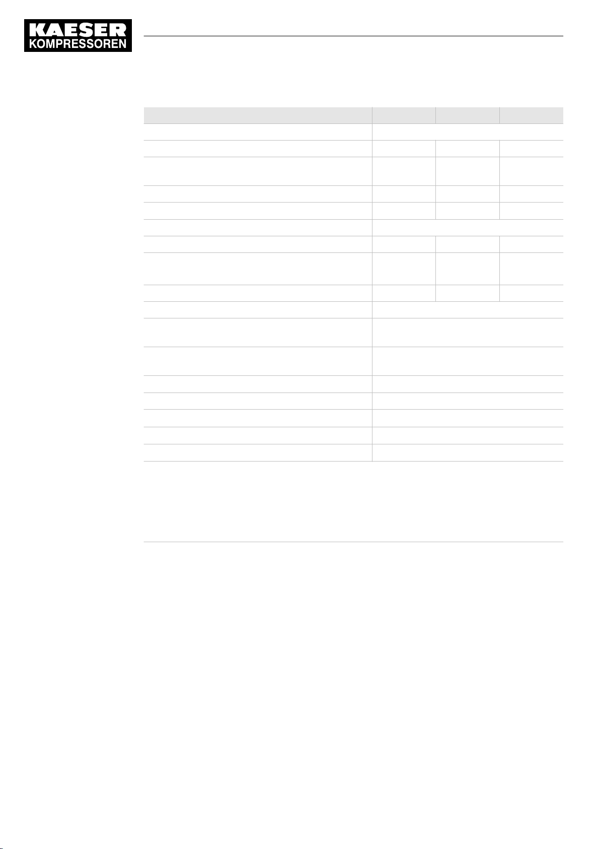
SAM 2 is available in diverse variants and options:
SAM 2 – 24 V DC
100-240 V AC
3x1.5
1x16
No.: 901735 00 E
■ In principle, every input and output is freely assignable.
■ The number of inputs and outputs can be increased using SBU (see chapter 4)
■ Details on assignable and assigned inputs and outputs can be found in the circuit dia‐
grams in the annex.
Service manual SIGMA AIR MANAGEMENT SYSTEM
SAM 2
5
Page 16
2 Technical Specifications
2.4 Components within the control cabinet
Model SAM 2-4 SAM 2-8 SAM 2-16
Basic configuration
Digital inputs (DI) for floating relay signals 6 6 6
Digital relay contact outputs (DOR) (as changeover
contacts, 230 V, 3 A)
Analog inputs (AII) 0(4)-20 mA 4 4 4
Free SIGMA NETWORK -Ports 7 7
Sequenced machines
Maximum 4 8 16
Via SIGMA NETWORK 4 7 13
I/O directly to SAM 2 4 4 4
Options
E1:PROFIBUS master
4)
E2: 7 SIGMA NETWORK -Ports. Factory-equipped with 7
E3: 13 SIGMA NETWORK -Ports
4)
E9: Network section control Network section control
E10: PROFINET IO
E11: ModbusTCP
E12: PROFIBUS DP
1)
PROFIBUS master only once ( SAM 2 or SBU ).
2)
with option E3: 13 SIGMA NETWORK -Ports.
3)
Expandable to 16 with SBU , see chapter 4.
4)
Either option E1 or E3 possible.
5)
Only one communication module possible.
5)
5)
5)
5 5 5
2)
7/13
2) 3)
Complete SAM PROFIBUS network can be
connected
SIGMA NETWORK ports
additional 6 SIGMA NETWORK -Ports.
PROFINET IO communication module
Modbus TCP communication module
PROFIBUS DP communication module
Tab. 5 Versions and Options
2.4 Components within the control cabinet
2.4.1 I/O modules (SAM 2 and SBU)
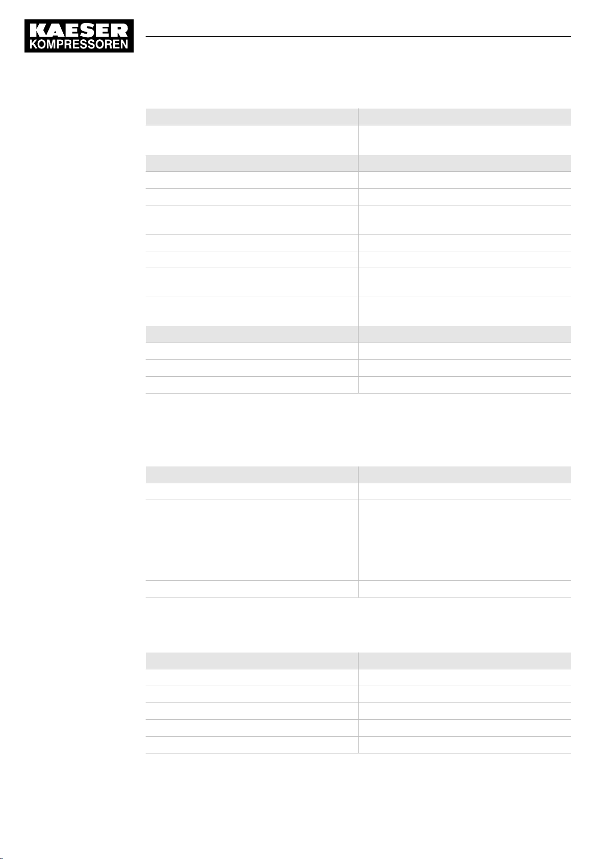
The following technical data apply to the I/O block and the individual I/O modules used in SAM 2
and SBU :
■ I/O block 6DI&6DOT&4AII
■ Module 6DI – X20DI6371
■ Module 6DOT – X20DO6322
■ Module 4AlI – X20AO2632
Service manual SIGMA AIR MANAGEMENT SYSTEM
6
SAM 2 No.: 901735 00 E
Page 17
2 Technical Specifications
2.4 Components within the control cabinet
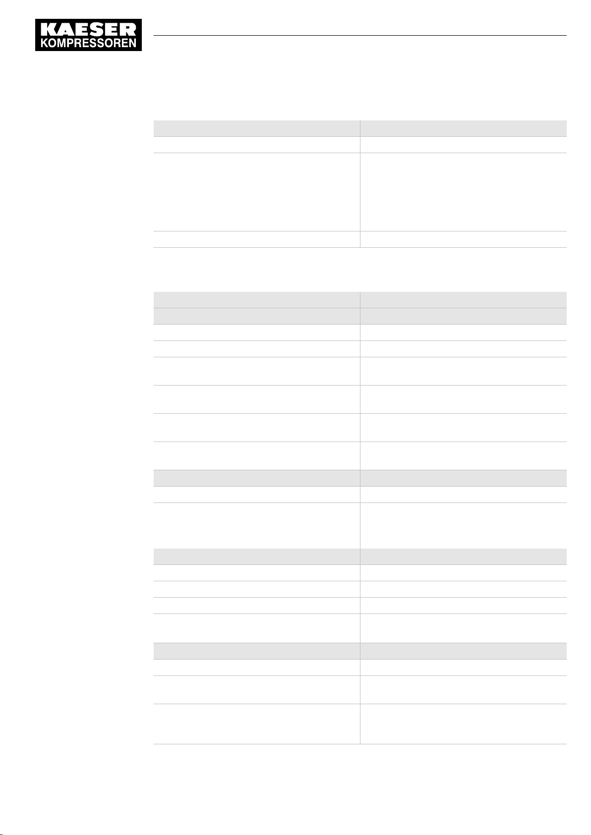
Technical data, all I/O modules
Feature Value
Connection terminals Push-in terminal
Connection diameter
■
Wire/single-core [mm2]
■
Flex/fine-core [mm2]
■
Wire end ferrule [mm2]
■
Double wire-end ferrule [mm2]
Display elements Status LEDs
Tab. 6 Technical data, all I/O modules
Technical data I/O-block and individual modules
Feature Value
Bus Controller X20BC0087-C01
Bus KAESER SIGMA NETWORK
Transfer rate [MBit/s] 10/100
Characteristics Auto crossing (Auto-MDI(X) ),
Connections 2 x SIGMA NETWORK -socket RJ45,
Max. length of the line between two compo‐
nents [m]
Electrical isolation SIGMA NETWORK -I/Omodule
24 V DC power supply X20PS9400
Power supply [V DC], [A] 24 (−15 % / +20 %), max. 0.7
Potential separation
■ Supply - internal bus
■ Supply - I/O module
Digital inputs (DI) Module 6DI – X20DI6371
Input voltage [V DC 24 (-15 % / +20 %)
Model. Input current at 24 V DC [mA] 3.75
Switching threshold [V DC] Low <5 , High >15
Insulation voltage between channel and bus
[V
]
eff
Digital outputs (DOT) Module 6DOT – X20DO6322
Output voltage [V DC] 24
Output current per output maximum (overvolt‐
age and short-circuit proof) [A]
Output protection Thermal shut-down at overvoltage or short-cir‐
Copper wires
■ 0.08-2.5 / AWG 28-14
■ 0.25-2.5 / AWG 24-14
■ 0.25-1.5 / AWG 24-16
■ 2x (0.25–0.75)
Auto negotiation
10/100Base-TX
100
Yes
—
■ Yes
■ No
500
0.5
cuit, integrated protection for switching inductive
loads
No.: 901735 00 E
Service manual SIGMA AIR MANAGEMENT SYSTEM
SAM 2
7
Page 18
2 Technical Specifications
2.4 Components within the control cabinet
Digital outputs (DOT) Module 6DOT – X20DO6322
Insulation voltage between channel and bus
[V
]
eff
Analogue Inputs (All) Module 4AlI – X20AO2632
Measuring range [mA] 0-20
Resolution [bit] 15
Connection type Active and passive possible
Ohmic resistance (internal) [Ohm] < 400
Input protection Protection against supply voltage wiring
Maximum error in 25 °C range from currently
measured value [%]
Maximum error in 25 °C offset from final value of
measuring range [%]
Distribution 24 VDC Module 6x 24 VDC - X20PD2113
Nominal output voltage [V DC] 24, Ground
Output current, total [A] 6.0
Fusing (internal, replaceable) [A], [mm] T6.3, 5x20
500
(2 conductor and 4 conductor technology)
0.08
0.02
Tab. 7 Technical data I/O-block and individual modules
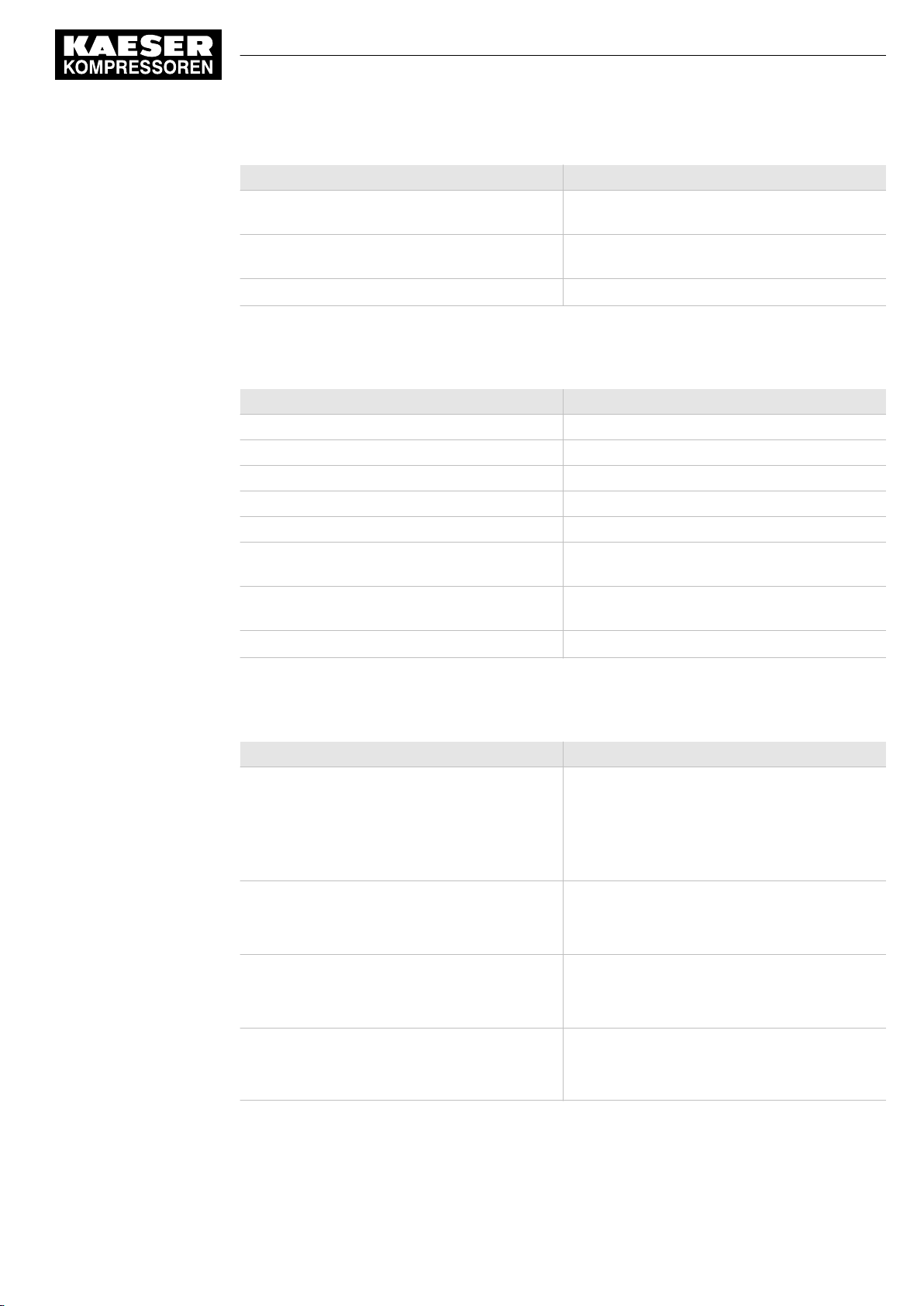
2.4.2 I/O Modules (only SBU)
The following technical data apply to the individual I/O modules used only in SBU :
Feature Value
Connection terminals Push-in terminal
Connection diameter
■
Wire/single-core [mm2]
■
Flex/fine-core [mm2]
■
Wire end ferrule [mm2]
■
Double wire-end ferrule [mm2]
Display elements Status LEDs
Tab. 8 Technical data, all I/O modules
2.4.2.1 Module 4AIR – X20AT4222
Feature Value
Analogue inputs for PT100 IEC/EN 60751 4
Range [ °C ] −200 – +850
Resolution [Bit] 16
Connection type Two-wire and three-wire technology
Measuring current [µA] 250
Copper wires
■ 0.08-2.5 / AWG 28-14
■ 0.25-2.5 / AWG 24-14
■ 0.25-1.5 / AWG 24-16
■ 2x (0.25–0.75)
Service manual SIGMA AIR MANAGEMENT SYSTEM
8
SAM 2 No.: 901735 00 E
Page 19
2 Technical Specifications
2.4 Components within the control cabinet
Feature Value
Maximum error in 25 °C range from current
measured value [%]
Maximum error in 25 °C offset from final value of
measuring range [%]
Isolation voltage input–internal bus [V
Tab. 9 Data, 4AIR module
2.4.2.2 Module 4AOI – X20AO2632
Feature Value
Analogue outputs 0–20 mA 2
Output range [mA] 0-20
Resolution [bit] 15
Max. ohmic resistance [Ohm] 500
Output protection Short-circuit-proof, current-limiting 40 mA
Maximum error in 25 °C range from current
measured value [%]
Maximum error in 25 °C offset from final value of
measuring range [%]
Isolation voltage output–internal bus [V
] 500
eff
] 500
eff
0.037
0.0015
0.045
0.025
Tab. 10 Data, 4AOI module
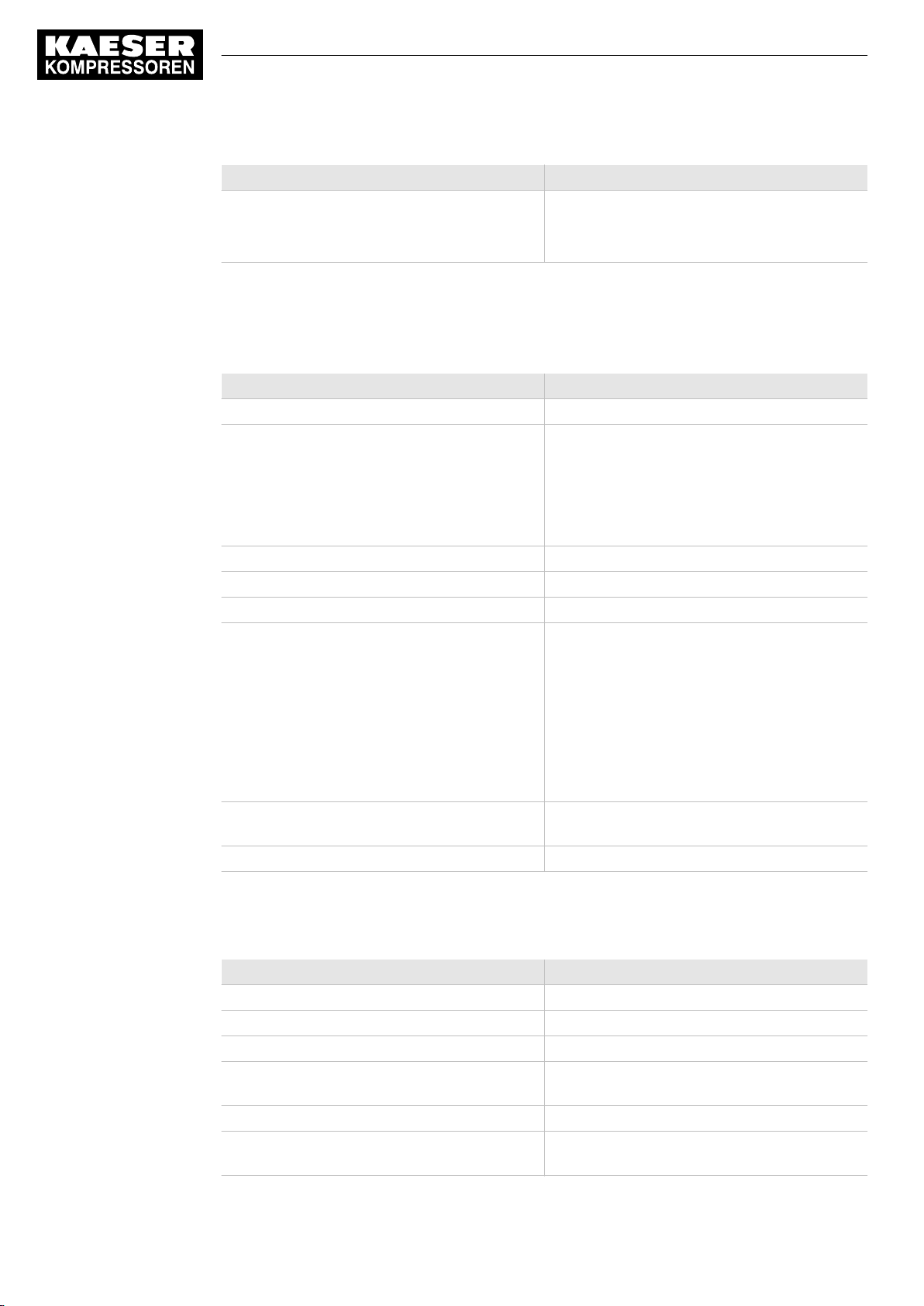
2.4.2.3 Module 4AIP – X20AP3121
Feature Value
Voltage, analogue inputs
■ Nominal voltage phase–phase max. [V AC],
[Hz]
■ Nominal voltage phase–N max. [V AC]
■ Maximum overload voltage
Current, analogue inputs
■ Maximum overload current
■ Resistance [mOhm]
Measuring accuracy
■ U
RMS
and I
RMS
[%]
■ Power [%]
Potential separation
■ Inputs–internal bus
■ Input–input
3
■ 480 at 50/60
■ 277
■ 1.5xUN permanent, 2xUN for 1 minute
4
■ 8xIN for 0.5s
■ 500
—
■ < 0.5
■ < 0.5
—
■ Yes
■ No
No.: 901735 00 E
Service manual SIGMA AIR MANAGEMENT SYSTEM
SAM 2
9
Page 20
2 Technical Specifications
2.4 Components within the control cabinet
Feature Value
Isolation voltage
■ Inputs–Internal bus [V DC]
■ Inputs–earth [V DC]
Tab. 11 Data module 4AIP
2.4.3 Relay block
The relay block comprises 5 relays ( SAM 2 ) or 6 relays ( SBU ) with the following technical data:
Feature Value
Connection terminals Push-in terminal
Connection diameter
■
Wire/single-core [mm2]
■
Flex/fine-core [mm2]
■
Wire end ferrule [mm2]
■ Double wire-end ferrule
Stripping length [mm] 8
Display elements Status LED
Coil voltage [V DC] 24
Output contact
■ Switching voltage [V]
■ Min. switching current [mA] (at 12 V)
■ Max. constant current [A]
■ Switching capacity IEC 60947/DIN VDE
0660
24 V DC13 [A]
230 V AC15 [A]
Inductive loads (e.g., auxiliary contact, solenoid
valve)
Rated isolation voltage [V AC] 250
—
■ 5500
■ 5500
Copper wires
■ 0.14-1.5 / AWG 26-16
■ 0.14-1.5 / AWG 26-16
■ 0.14-1.5 / AWG 26-16
■ not possible
1 changeover contact
■ 5 (at 100 mA) – 250 V AC/DC
■ 10
■ 6
■ —
1
3
to be connected with RC elements
10
Tab. 12 Relay block data
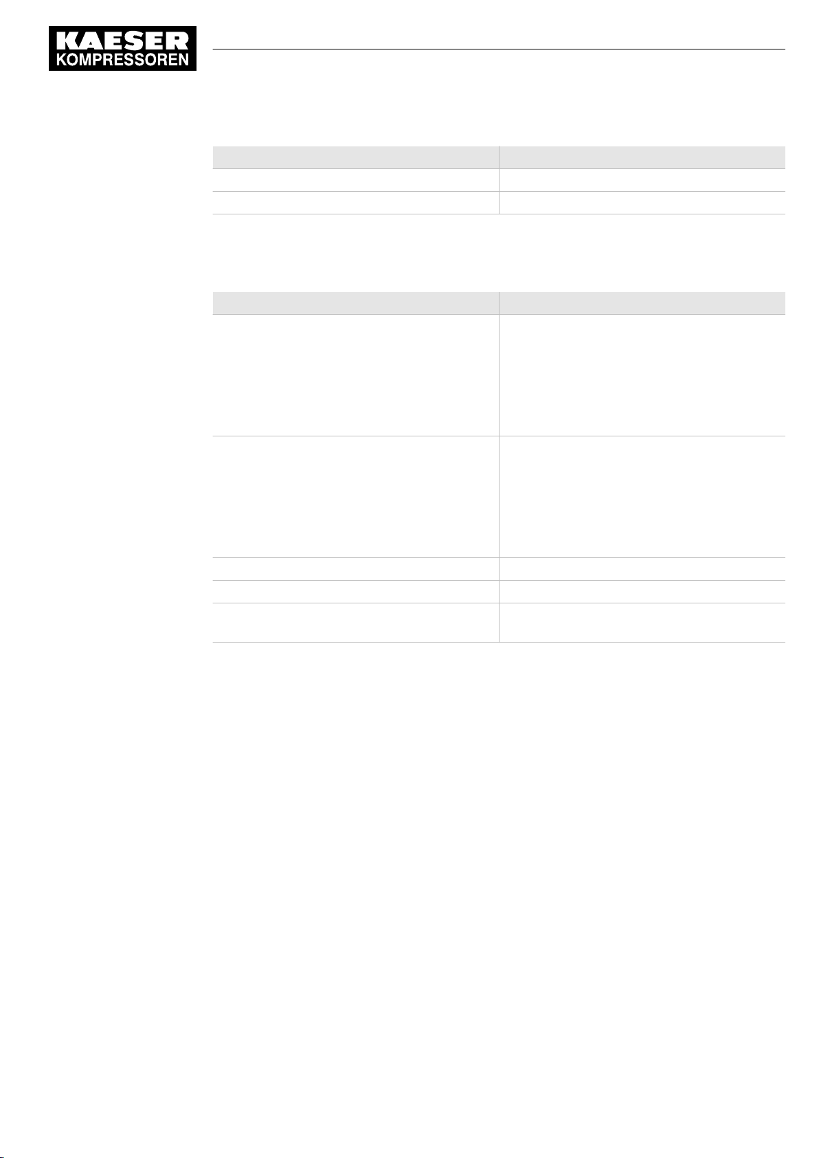
2.4.4 SIGMA NETWORK Switch 8 port
Feature Value
KAESER SIGMA NETWORK ports 8
Transfer rate [Mbps] 10/100
Transfer mode Store-and-forward switching mode
Characteristics Auto crossing (Auto-MDI(X) ),
Connections RJ45, 10/100Base-TX
Max. conduit length between two components
[m]
Service manual SIGMA AIR MANAGEMENT SYSTEM
SAM 2 No.: 901735 00 E
Auto negotiation, Auto sensing
100
Page 21
2 Technical Specifications
2.4 Components within the control cabinet
Feature Value
Power supply [V DC] 9–48, @ 24 V DC/200 mA
Display elements Status LEDs for voltage and every port
Tab. 13 Data switch
2.4.5 Protocol converter SIGMA NETWORK / PROFIBUS master
Feature Value
SIGMA NETWORK
■ Transfer rate
■ Properties 1
■ Properties 2
■ Max. conduit length between two compo‐
nents [m]
PROFIBUS DP
■ Transfer rate [kBit/s]
■ Interface
■ Connections
■ Max. conduit length for the entire bus length
[m]
Power supply [V DC] 24 +/-25 %, typ. @ 130 mA
Display elements Status LED
Service interfaces Mini USB, slot for MMC memory card, rotary
—
■ 10/100
■ Auto crossing
■ Auto negotiation
■ 100
Master
■ 187.5
■ RS486 floating
■ 9-pole SUB-D socket
■ 800
switch
Tab. 14 Data, SNW/DP bus controller
2.4.6 SAM 2 -Terminal
2.4.6.1 Industrial computer
■ Industrial computer with Quad core processor
■ 2 GB RAM
■ 16 GB flash memory
■ Buffer battery for real-time clock
■ Voltage and temperature monitoring
■ Update-capable with SD memory card
2.4.6.2 Interfaces
The positions of the interfaces X1–X5 are marked on the rear of the SAM 2 terminal.
No.: 901735 00 E
Service manual SIGMA AIR MANAGEMENT SYSTEM
SAM 2
11
Page 22
2 Technical Specifications
2.4 Components within the control cabinet
Interface Connection Marking
Com modules
Battery
1)
2)
SD card Slot for SD/SDHC/SDXC memory
USB 2.0
USB 3.0
1)
1)
SIGMA NETWORK RJ485 socket (10/100Base T) X6
Ethernet 1 Gb RJ485 socket (1000Base T) X7
24 V DC Power supply, protected against
FE Equipotential bonding 6.3 mm flat
1)
Slot/interface covered: Remove the cover if a communication module is installed.
2)
Slit covered: Remove the cover if an additional buffer battery is installed (see chapter 10.2).
Slot for KAESER communication
modules
For additional buffer battery X2
card
For service purposes only X4
For service purposes only X5
polarity reversal
plug
X1
X3
X8
X9
Tab. 15 Interfaces SAM 2
Identification with RFID Equipment Card
Feature Value
Integrated hardware RFID write/read device
Hardware (external) KAESER Equipment Card
Recognition in maximal distance [m] 0.05
Frequency [MHz] 13.56
Tab. 16 RFID
2.4.6.3 Display
Feature Value
Display model Colour display with touch screen
Display resolution [px1)]
Format 12,1”; 16:10
Background lighting LED
Model LCD; industrial version
Touch operation Capacitive
Sensor keys 4
1)
px ≙ Pixel
1280 x 800
12
Tab. 17 Display data
Service manual SIGMA AIR MANAGEMENT SYSTEM
SAM 2 No.: 901735 00 E
Page 23
2 Technical Specifications
2.5 Control cabinet
2.4.6.4 Software
SAM 2 terminal:
■ Operating system: Linux
■ KAESER controller software
■ KAESER user interface
2.5 Control cabinet
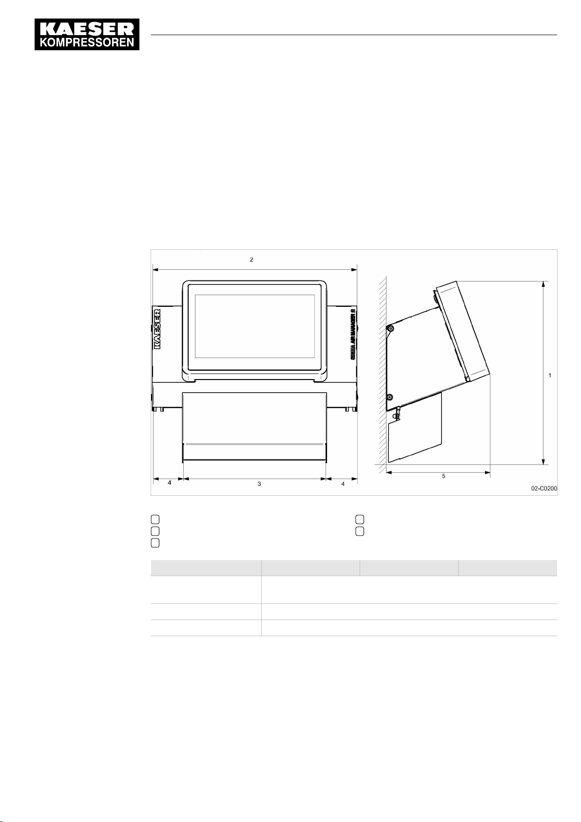
Terminal and control cabinet
No.: 901735 00 E
Fig. 1 Control cabinet dimensions
1 483 mm
2 540 mm
3 380 mm
Model SAM 2-4 SAM 2-8 SAM 2-16
Material Enclosure: Sheet metal, painted RAL 9007 grey
Mass [kg] 15
Enclosure protection IP54
Tab. 18 Control cabinet data
Service manual SIGMA AIR MANAGEMENT SYSTEM
SAM 2
4 80 mm
5 284 mm
Cover: Plastic, RAL 7016, anthracite grey
13
Page 24
2 Technical Specifications
2.6 Pressure transducer
2.6 Pressure transducer
Models I and II pressure transducers
Model I II
Measurement range [bar] 0-1 0–6/10/16/20/32/45
Overload limit [bar] 3.5 double final pressure
Deviation of characteristic from final value
Limit setting [%]
Air connection, male thread G 1/2 B DIN 16288
Nominal temperature range [ °C ] –20...+80 –25...+85
Nominal temperature range [K] 253-353 248-358
Fluid temperature range [ °C ] –30...+100 –40...+100
Fluid temperature range [K] 243-373 233-373
Storage temperature range [ °C ] –40...+100 –40...+100
Storage temperature range [K] 233-373 233-373
Temperature influence / 10 K over the range [%] ± 0.2 ± 0.15
Temperature influence / 10 K over the range [%] ± 0.2 ± 0.15
Output signal (two-wire technique) [mA] 4-20 4-20
Power supply connection
(plug to EN 175301-803)
Enclosure Stainless steel Stainless steel
Enclosure protection IP 65 IP 65
Tightening torque [Nm] 17-20 17-20
≤ 0.5 ≤ 0.5 (0.25 typical)
G 1/4 A DIN 3852
Stainless steel
PG 11 PG 9
Stainless steel
Viton seals
Tab. 19 Models I and II pressure transducers
Pressure transducer model III and vacuum
Model III Vacuum pump
Measurement range [bar] 0-16 –
Measurement range, absolute [bar] – 0-1
Overload limit [bar] 32 3
Deviation of characteristic from final value
Limit setting [%]
Air connection, male thread G 1/2 A G 1/2 A
Air connection, male thread G 1/8 A G 1/8 A
Rated temperature range [ °C ] –25...+85 –25...+85
Rated temperature range [K] 248-358 248-358
Fluid temperature range [ °C ] –30...+125 –30...+125
Fluid temperature range [K] 243-373 243-373
Storage temperature range [ °C ] –50...+100 –50...+100
≤ 1 (0.5 typical) ≤ 1 (0.5 typical)
14
Service manual SIGMA AIR MANAGEMENT SYSTEM
SAM 2 No.: 901735 00 E
Page 25
2 Technical Specifications
2.6 Pressure transducer
Model III Vacuum pump
Storage temperature range [K] 233-373 233-373
Temperature influence / 10 K over the range [%] ± 0.4 ± 0.4
Temperature influence / 10 K over the range [%] ± 0.4 ± 0.4
Output signal (two-wire technique) [mA] 4-20 4-20
Power supply connection
(plug to EN 175301-803)
Enclosure brass brass
Enclosure protection IP 65 IP 65
Tightening torque [Nm] 17-20 17-20
Tab. 20 Pressure transducer model III and vacuum
PG 9 PG 9
No.: 901735 00 E
Service manual SIGMA AIR MANAGEMENT SYSTEM
SAM 2
15
Page 26

3 Safety and Responsibility
3.1 Basic instructions
3 Safety and Responsibility
3.1 Basic instructions
DANGER
Disregarding these instructions can result in serious injury.
➤ To operate the product SAM 2 safely, read the service manual carefully and take notice
of its contents.
The product SAM 2 is manufactured to the latest engineering standards and acknowledged safety
regulations. Nevertheless, dangers can arise through the operation:
■ danger to life and limb of the operator or third parties,
■ impairments to the SAM 2 and other material assets.
➤ Therefore, observe the following:
■ Use the product SAM 2 only if it is in a technically perfect condition and only for the pur‐
pose for which it is intended; observe all safety measures and the instructions in the serv‐
ice manual.
■ In particular, immediately rectify (have rectified) any faults that could be detrimental to
safety.
3.2 Intended use
Specified use also includes compliance with the instructions in this manual.
The product SAM 2 is intended exclusively for the operation of compressors, blowers and vacuum
systems in industrial fields and may only be operated within its associated control cabinet. Any oth‐
er use is considered incorrect. The manufacturer is not liable for any damages that may result from
incorrect use. The user alone is liable for any risks incurred.
➤ Comply with the instructions in this operating manual.
➤ Operate the product only within its performance limits and under the permitted ambient condi‐
tions.
3.3 Improper use
Specified use also includes compliance with the instructions in this manual.
Converting or changing the SAM 2 constitutes improper use. The manufacturer's warranty is made
invalid in such cases.
Improper usage can cause damage to property and/or (severe) injuries.
1. Use SAM 2 only as intended.
2. Do not use SAM 2 to control other machines or products for which SAM 2 is not intended.
3. Do not allow conversions or changes.
16
Service manual SIGMA AIR MANAGEMENT SYSTEM
SAM 2 No.: 901735 00 E
Page 27

3 Safety and Responsibility
3.4 User's Responsibilities
3.4 User's Responsibilities
3.4.1 Observe statutory and universally accepted regulations
This is, for example, nationally applied European directives and/or valid national legislation, safety
and accident prevention regulations.
➤ Observe relevant statutory and accepted regulations during installation, operation and mainte‐
nance of the equipment.
3.4.2 Qualified personnel
These are people who, by virtue of their training, knowledge and experience as well as their knowl‐
edge of relevant regulations can assess the work to be done and recognise the possible dangers
involved.
Authorised operators possess the following qualifications:
■ are of legal age,
■ are conversant with and adhere to the safety instructions and sections of the service manual
relevant to operation,
■ have received adequate training and authorisation to operate electrical and compressed air de‐
vices.
Authorised installation and maintenance personnel have the following qualifications:
■ are of legal age,
■ have read, are conversant with and adhere to the safety instructions and sections of the serv‐
ice manual applicable to installation and maintenance,
■ are fully conversant with the safety concepts and regulations of electrical and compressed air
engineering,
■ are able to recognise the possible dangers of electrical and compressed air devices and take
appropriate measures to safeguard persons and property,
■ have received adequate training and authorisation for the safe installation and maintenance on
this equipment.
➤ Ensure that operating, installation and maintenance personnel are qualified and authorised to
carry out their tasks.
3.5 Dangers
The general safety instructions in this chapter describe possible dangers and how to deal with
them. Special safety instructions are found in this service manual at the beginning of each chapter
or directly before a task instruction.
➤ Take full heed of all safety instructions.
3.5.1 Safely dealing with sources of danger
No.: 901735 00 E
Electricity
➤ Disconnect the machine from all power supply phases.
➤ Switch off any external power sources.
Service manual SIGMA AIR MANAGEMENT SYSTEM
SAM 2
17
Page 28

3 Safety and Responsibility
3.6 Warranty
Voltage is still present on the marked terminals (orange or labelled) in the SAM 2 when the
power supply is switched off.
➤ Check and ensure that no power is present.
➤ Before switching on again make sure that
■ no maintenance personnel are working,
■ all panels are in place,
■ all access doors are closed.
➤ Allow only qualified electricians or trained personnel under the supervision of a qualified electri‐
cian to carry out work on electrical equipment according to electrical engineering regulations.
➤ Observe all accepted safety regulations and national legislation applicable to all work carried
out on the SAM 2 .
➤ Use fusing according to current draw (see chapter 2).
➤ Make electrical connections only with power removed and check regularly for tightness and
condition.
➤ Use only electrical cables that are suitable and approved for the surroundings and electrical
loads applied.
➤ Before every start-up by the user of machines that are linked to the master controller, make
sure there is adequate protection against electric shock from direct or indirect contact and
check regularly.
3.5.2 Safe SAM 2 operation
Pay attention to the following points to avoid damage to the SAM 2 :
➤ Do not remove any plugs on the SAM 2 while the compressed air system is in operation.
➤ Operate the SAM 2 only when all supplies are connected.
1. WARNING!
A short circuit can cause irreversible damage to the PROFIBUS interface.
➤ Avoid short-circuits.
2. Avoid short circuits on the power supply pins in the PROFIBUS interface for PROFIBUS/
SIGMA NETWORK converter.
➤ Never modify, bypass or disable safety devices.
➤ Do not remove or obliterate labels and notices.
➤ Use only spare parts approved by the manufacturer for use in SAM 2 .
3.6 Warranty
This service manual does not contain any independent warranty commitment. Our general terms
and conditions apply with regard to warranty.
Prerequisite for granting warranty is the intended and proper use of the product in compliance with
the specific application conditions.
In view of the multitude of potential applications, it is the duty of the operator to verify that the prod‐
uct is suitable for the actual application.
18
Furthermore, we do not assume any warranty obligation for damages caused by:
■ the use of unsuitable parts or operating materials,
■ arbitary modifications,
Service manual SIGMA AIR MANAGEMENT SYSTEM
SAM 2 No.: 901735 00 E
Page 29

3 Safety and Responsibility
3.6 Warranty
■ incorrect maintenance,
■ incorrect repair.
Correct maintenance and repair means the use of genuine Kaeser spare parts.
➤ Obtain confirmation from KAESER that your specific operating conditions are suitable.
No.: 901735 00 E
Service manual SIGMA AIR MANAGEMENT SYSTEM
SAM 2
19
Page 30

4 Design and Function
4.1 Overview
4 Design and Function
4.1 Overview
The SAM 2 is used for the control, regulation and monitoring of stations comprising multiple com‐
pressors, blowers or vacuum machines in a commercial environment. SAM 2 reacts flexibly to fluc‐
tuating compressed air demand and thus reduces energy consumption. The system takes into ac‐
count machine run times and deployment priorities. Important parameters are clearly represented
as coloured graphic elements. The high-resolution touch screen enables user-friendly settings.
SAM 2 is offered as:
■ SAM 2-4
■ SAM 2-8
■ SAM 2-16
They differ in the number of controllable machines (see chapter 2 "Design variants and options").
Using the SBU , you can flexibly expand the number of interfaces.
SAM 2 comprises the following components:
■ The central pressure transducer measures the pressure in the air network and passes the val‐
ue to SAM 2 .
■ The processing unit of the SAM 2 decides according to default parameters, which machines
are switched to load to keep the pressure in the air main constant. All data are clearly graphi‐
cally represented. You can analyse and archive the data provided.
■ The display and control panel of the touch screen provides information on current pressure and
other parameter values and offers various possibilities for individual settings.
Compressors with SIGMA CONTROL and SIGMA CONTROL 2 as well as those with conventional
controllers can be linked to SAM 2 .
20
Service manual SIGMA AIR MANAGEMENT SYSTEM
SAM 2 No.: 901735 00 E
Page 31
4 Design and Function
4.1 Overview
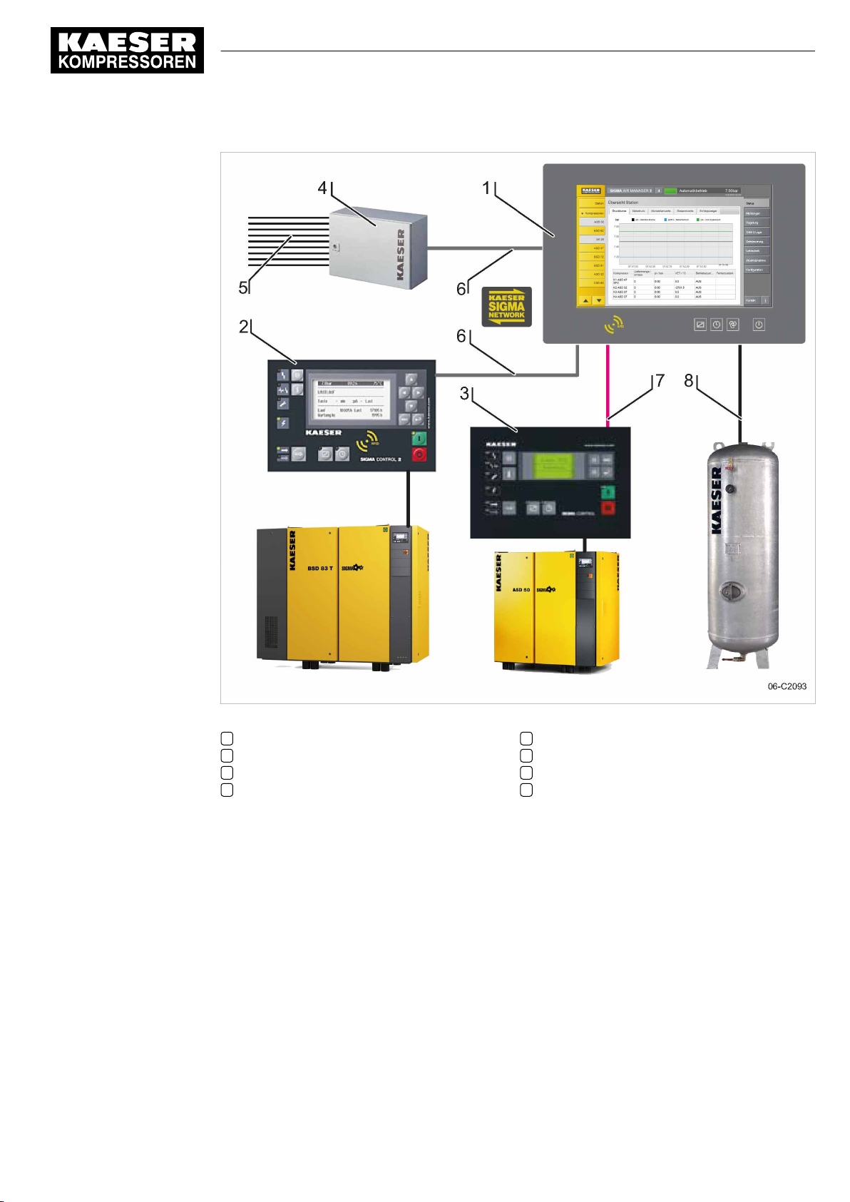
Fig. 2 SAM 2 – Standard design of a compressed air station
1 SAM 2
2 SIGMA CONTROL 2
3 SIGMA CONTROL
4 SBU
5 I/O lines to machines and sensors
6 SIGMA NETWORK
7 PROFIBUS
8 Analogue input for pressure transducer
No.: 901735 00 E
Service manual SIGMA AIR MANAGEMENT SYSTEM
SAM 2
21
Page 32
4 Design and Function
4.2 Operating panel
4.2 Operating panel
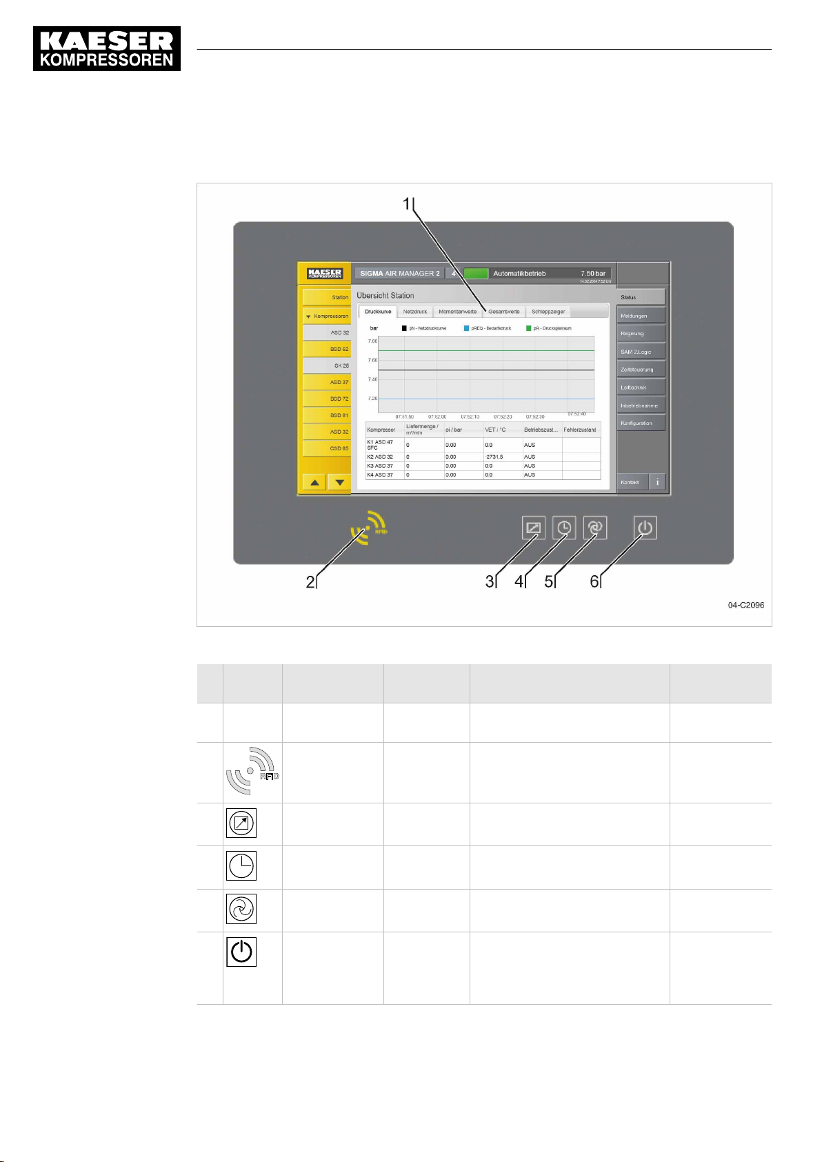
Fig. 3 Operating panel SAM 2
No. Sign Operating
element
1 — Touch screen — Operation of SAM 2 functions Chapter 4.3
2 RFIL write/read
device
3 Button remote
control
4 Button time
control
5 Button
automatic
6 Button station
On/Off
Tab. 21 Operating panel SAM 2
Key
illumination
— Log-on with RFID Equipment
Green Activation and deactivation of the
Green Switch the clock on or off
Green Switch the station between man‐
Green/red Compressed air station activation
Function Description
Card
remote operation.
ual and automatic mode.
(air supply) or
deactivation (ATTENTION: no air
supply!)
"Touch screen"
Chapter 4.4
"User log-on"
Chapter 7.2 8.1
Switch on
"SAM 2"
22
Service manual SIGMA AIR MANAGEMENT SYSTEM
SAM 2 No.: 901735 00 E
Page 33
4 Design and Function
4.3 Touch screen
4.3 Touch screen
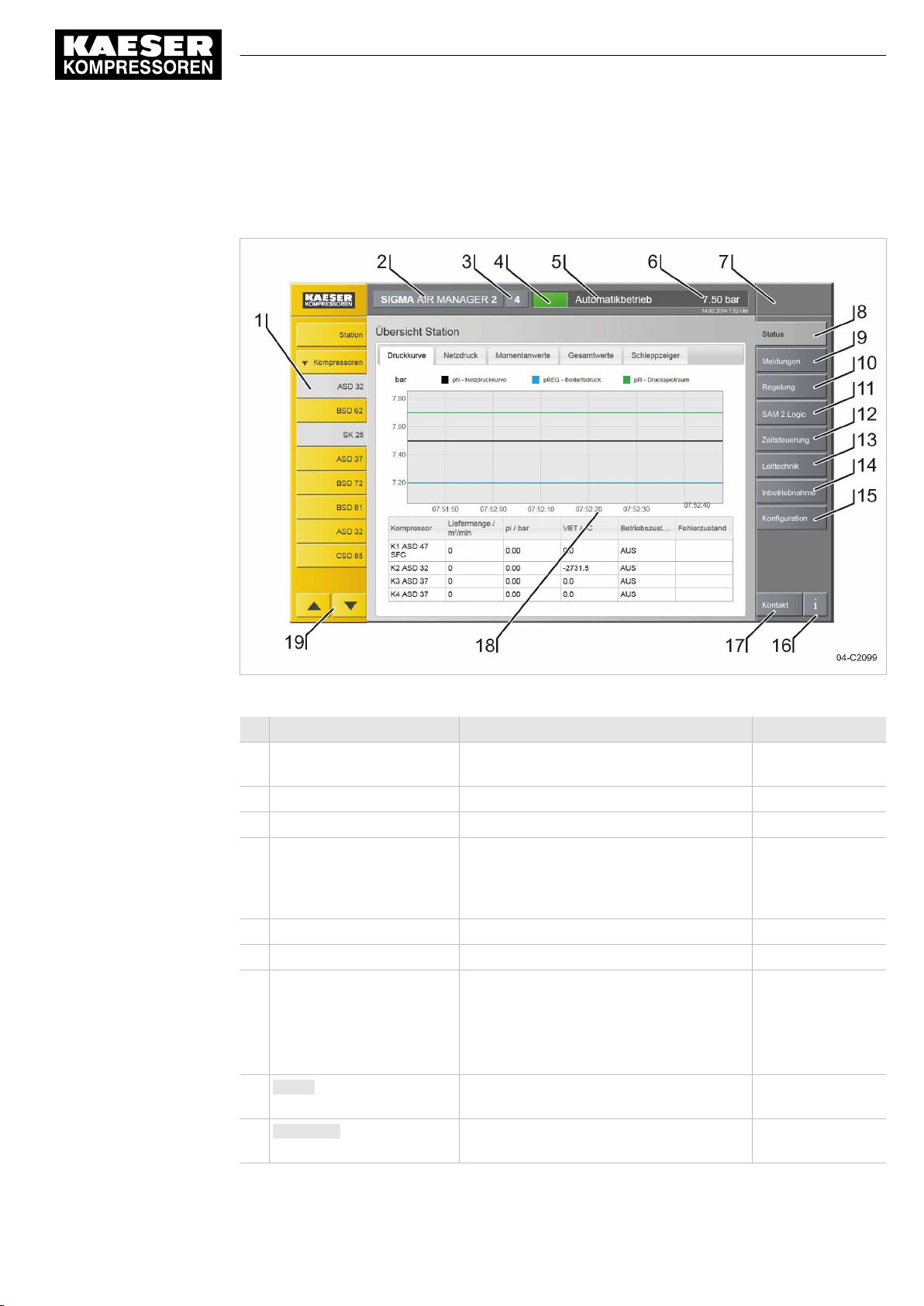
The touch screen menu is arranged as follows:
Fig. 4 Touch screen menu
No. Menu element Function Description
1 Device selection list Selection of machines, individually or by
2 Product designation — —
3 SAM 2 model e.g., SAM 2-4 —
4 System status Traffic lights function:
5 Operating mode Display of the set operating mode —
6 Pressure chart Display of current system pressure —
7 Access mode Display of current access mode:
8 Status Call up Status menu Chapter 8.3.1
9 Messages Call up Messages menu Chapter 9.2
—
groups
—
green: Operation
yellow: Maintenance/warning
red: Fault (air supply is endangered!)
Chapter 7.4 "User
log-on"
■ — (logged out)
■ Operating
■ Monitoring
"Main menu"
"Messages"
No.: 901735 00 E
Service manual SIGMA AIR MANAGEMENT SYSTEM
SAM 2
23
Page 34
4 Design and Function
4.4 User log-on with RFID
No. Menu element Function Description
10 Control Call up Control menu Chapter 7.12
"Control"
11 SAM 2.Logic Logic functions are programmed here
12 Time control Call up Timer menu
13 Process control Call up Control technology menu
14 Start-up Menus for commissioning the compressed
air station
15 Configuration Configuration menus for SAM 2 Chapter 7 "Station"
16 Info Call up Help menu Chapter 8.2 "Help
17 KAESER Service Support Call up Contact menu —
18 Display Touch screen display for graphics, messag‐
es and data
19 Device selection UP/DOWN Device selection list; scrollbar provided for
more than 10 devices
Chapter 7 "Initial
Start-up"
function"
—
—
Tab. 22 Touch screen menu elements
4.4 User log-on with RFID
The KAESER Equipment Cards provide various functionalities:
■ Switch between three operating modes:
─ Logged out
─ Monitoring
─ Operating
■ Encryption ensures security
■ Different access levels for the customer (Equipment Card) and Service (Key)
The system records which user is when logged on at SAM 2 . You can thus determine who was
logged on when specific messages or other events have occurred.
24
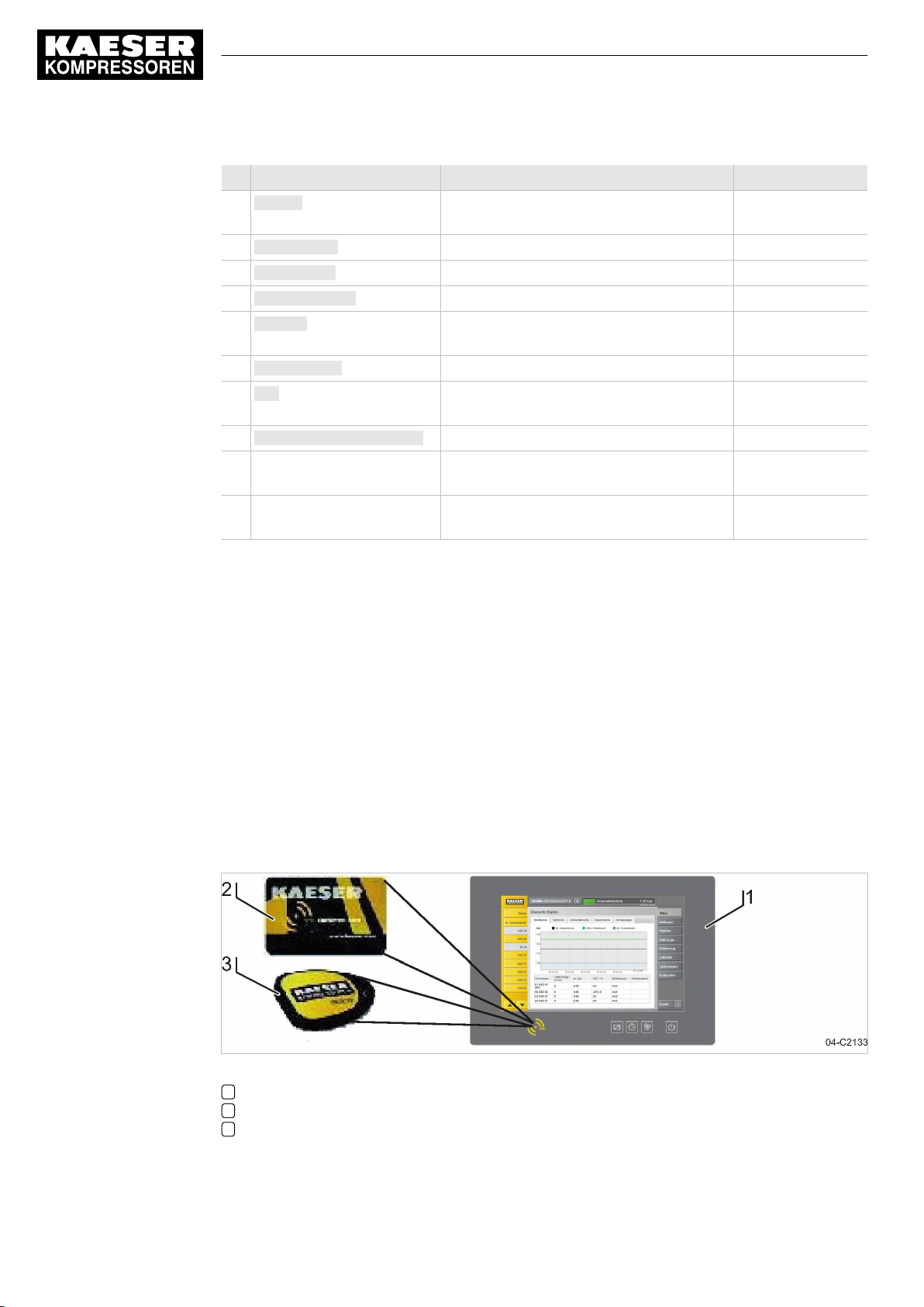
Fig. 5 User management with RFID
1 SAM 2
2 KAESER Equipment Card
3 KAESER Key
Service manual SIGMA AIR MANAGEMENT SYSTEM
SAM 2 No.: 901735 00 E
Page 35
4 Design and Function
4.5 Main menu
4.5 Main menu
The menu has the following sub-menus:
■ "Net pressure station"
■ "Net pressure"
■ "Current values"
■ Total values
■ "Drag Indicator"
■ "View station"
If the menu page displayed has several sub-menus, touch one of the tabs to open the correspond‐
ing sub-menu.
4.5.1 Menu tree
The menu elements and sub-menus available from the main menu depend in part on the se‐
lected machine or the multiple machines selected at once.
Main menu element Sub-menu element
Status ■ Chapter 8.3.1 "Overview"
■ Chapter 8.3.5 "View station"
Messages ■ Chapter 9.2 "Unacknowledged messages"
■ Chapter 9.2 "Current reports"
■ Chapter 9.2 "Message history"
Control ■ Chapter 7.12 Settings
■ Chapter 7.12 Pressure parameters
SAM 2.Logic ■ Chapter "Editor"
Time control ■ Chapter Status
■ Chapter Editor
Process control ■ Chapter Status
■ Chapter Editor
Start-up ■ Chapter 7.3 Station
■ Chapter 7.11 "P+I diagram"
■ Chapter 7.10 SIGMA NETWORK
■ Chapter 7.10 PROFIBUS
Configuration ■ Chapter 7.7 "E-Mail"
■ Chapter 7.6 "Unit settings"
■ Chapter "User management"
■ Chapter 11.4 "Software versions"
■ Chapter 7.5 "Date and time"
■ Chapter 7.9 "Data recording"
■ Chapter 7.3 "Language"
No.: 901735 00 E
Service manual SIGMA AIR MANAGEMENT SYSTEM
SAM 2
25
Page 36

4 Design and Function
4.6 Operation and function
Main menu element Sub-menu element
Tab. 23 Menu tree
4.6 Operation and function
SAM 2 has been developed for a multitude of possible applications. Generally, most of the default
settings can be kept or have to be changed only slightly.
4.6.1 Adaptive 3D control
The adaptive 3D control minimises the energy requirements of the compressed air station by auto‐
matically adapting to the operating conditions.
It automatically adapts the selection of the machines to be activated and deactivated as well as the
cut-out and cut-in pressures for the selected machines to the current operating conditions of the
compressed air station.
■ Chapter 7.10 "Peripherals"
4.6.2 Base load sequencing
The controller will equally use machine of the same size. The standard for comparison is the num‐
ber of operating hours. The machine with the least number of operating hours is used the most.
4.6.3 Time control
The compressed air system can be operated via an integrated timer. There are 32 switching points
per week available.
4.6.4 Power limiting
If the power limiting function is activated, the system will add machines only to the point where the
overall load capacity of the running machines exceeds the specified power limit. The nominal pres‐
sure and the maximum speed are used for calculating the overall load capacity.
4.6.5 Air main charging
After the activation of the compressed air station, the air network is charged at the specified net‐
work charging speed.
4.6.6 EMERGENCY operation
A compressed air station can run in EMERGENCY operation if each machine has its own system
pressure switch or presser control system. This is always the case with KAESER rotary screw
compressors. Compressed air systems with rotary blowers or reciprocating compressors may or
may not have machines provided with their own system pressure switches. Stations with machines
without system pressure switches cannot operate in EMERGENCY mode. These compressed air
systems cannot deliver compressed air without SAM 2 .
26
Service manual SIGMA AIR MANAGEMENT SYSTEM
SAM 2 No.: 901735 00 E
Page 37

4 Design and Function
4.6 Operation and function
Compressor stations with EMERGENCY mode (manual mode)
EMERGENCY mode can cause large pressure swings in the air main.
The connected machines are automatically switched to EMERGENCY mode:
■ When the voltage supply of SAM 2 fails in activated state
■ When the connection to the pressure transducer is interrupted
■ When SAM 2 itself fails
The machines then run under their internal pressure regulation, independent of SAM 2 . The ma‐
chines can be manually switched to EMERGENCY operation (manual mode) for test purposes.
Compressor stations without EMERGENCY mode (manual mode)
No compressed air is delivered without SAM 2 .
The output relays switch off:
■ When the voltage supply of SAM 2 fails
■ When the connection to the pressure transducer is interrupted
■ When SAM 2 itself fails
This causes the connected machines to switch to idle or off. The compressed air system no longer
delivers compressed air.
4.6.7 Visualisation at external devices
The user interface of SAM 2 can be represented at an external computer (PC, laptop, tablet). For
this purpose, SAM 2 must be connected to the external computer via the Gigabit Ethernet connec‐
tion X7, directly via a network cable or indirectly (network). A web browser is used for the visualisa‐
tion.
No.: 901735 00 E
Service manual SIGMA AIR MANAGEMENT SYSTEM
SAM 2
27
Page 38
5 Installation and Operating Conditions
5.1 Environment
5 Installation and Operating Conditions
5.1 Environment
Temperature range
Ambient temperatures
Min. ambient temperature Maximum ambient temperature
0 °C 45 °C
Tab. 24 Ambient temperatures
Storage temperatures
Minimum storage temperature Maximum storage temperature
−20 °C 70 °C
Tab. 25 Storage temperatures
Comply with permissible ambient temperatures:
1. Check ambient temperature.
2. Adjust equipment location to suitable ambient temperature range.
Comply with the specified storage temperature:
1. Check temperature of storage location.
2. Determine the storage location according to a suitable temperature range.
5.2 Installation conditions
SAM 2 is designed for the operation in an industrial environment with proprietary supply network
separated from the public supply by a transformer or generator.
➤ Install SAM 2 as appropriate.
28
Service manual SIGMA AIR MANAGEMENT SYSTEM
SAM 2 No.: 901735 00 E
Page 39

6 Installation
6.1 Installation
6 Installation
6.1 Installation
Connection SIGMA CONTROL
and
SIGMA CONTROL 2
Ensuring safety x x Chapter 6.2 "Ensuring
Reporting transport dam‐
age
Compressed air supply
during installation
Scope of delivery x x Chapter 6.5 "Scope of
Installing the control cabi‐
net
Identifying the machines x x Chapter 6.7 "Identify‐
Connecting the pressure
transducer
Planning the wiring x x Chapter 6.9 "Planning
Laying cables x x Chapter 6.10 "Laying
Creating
SIGMA NETWORK
Creating the PROFIBUS
network
Setting up the compres‐
sor station via floating re‐
lay contacts
Connecting the cables to
SAM 2
Setting up the machines x x Chapter 6.12 "Setting
x x Chapter 6.3 "Reporting
x x Chapter 6.4 "Com‐
x x Chapter 6.6 "Installing
x x Chapter 6.8 "Connect‐
x − Chapter 6.10.1 Creat‐
x − Chapter 6.10.2 "Creat‐
− x Chapter 6.10.3 "Set‐
x x Chapter 6.11 Connect‐
Conventional Description
safety"
transport damage"
pressed air supply dur‐
ing installation"
delivery"
the control cabinet"
ing the machines"
ing the pressure trans‐
ducer"
the wiring"
cables"
ing
"SIGMA NETWORK"
ing the Profibus net‐
work"
ting up the compressor
station via floating re‐
lay contacts"
ing the cables to
"SAM 2"
up the machines"
No.: 901735 00 E
Tab. 26 Installation overview
Service manual SIGMA AIR MANAGEMENT SYSTEM
SAM 2
29
Page 40

6 Installation
6.2 Ensuring safety
6.2 Ensuring safety
Follow the instructions below for safe installation.
Warning instructions are located before a potentially dangerous task.
Disregard of warning instructions can cause serious injuries!
Complying with safety notes
Disregard of safety notes can cause unforeseeable dangers!
➤ Comply with the instructions in chapter 3 Safety and Responsibility .
➤ This product may only be installed by a qualified person. See chapter 3, "Assigning personnel".
When working on live components
Touching voltage carrying components can result in electric shocks, burns or death.
➤ Work on electrical equipment may only be carried out by authorised electricians.
➤ Switch off and lock out the power supply disconnecting (isolating) device and check that no
voltage is present.
➤ Check that there is no voltage on potential-free contacts.
6.3 Reporting transport damage
1. Check the product for visible and hidden transport damage.
2. Immediately notify the carrier and the manufacturer in writing of any damage.
6.4 Compressed air supply during installation
➤ Check the compressor station's EMERGENCY mode characteristics.
■ Station with emergency operating mode: Chapter 6.4.1
■ Stations without emergency operating mode: Chapter 6.4.2
6.4.1 Station with emergency operating mode
It is possible to install and commission SAM 2 without shutting down the complete air system.
30
DANGER
Mortal danger from electric current
➤ The machine must be free of voltage before work commences.
1. Isolate the machine from all sources of voltage.
2. Make sure the machine is voltage-free.
3. Connect the machine to SAM 2 (chapters 6.9 to 6.10).
4. Put the machine back into operation.
5. Repeat steps 1 to 3 for any further machines.
6. Perform the commissioning and setting as detailed in chapter 7.
Service manual SIGMA AIR MANAGEMENT SYSTEM
SAM 2 No.: 901735 00 E
Page 41
6 Installation
6.5 Scope of delivery
7. Do not switch SAM 2 from manual to automatic mode until these settings have been comple‐
ted.
SAM 2 subsequently assumes control of the machines.
Further information For EMERGENCY mode, see chapter "EMERGENCY mode".
6.4.2 Stations without emergency operating mode
SAM 2 is required for the supply of compressed air. The compressed air system is not operational
until initial start-up of SAM 2 is completed.
➤ Switch on the compressor station after commissioning SAM 2 .
Further information For EMERGENCY mode, see chapter "EMERGENCY mode".
6.5 Scope of delivery
This product comprises at least the following components (depending on the selected configura‐
tion, additional components may be provided):
Item Material Name
10 SAM2.1 SAM 2 (SAM 2-4, SAM 2-8 or SAM 2-16)
20 "Pressure-dependent" Pressure transducer
30 2x KAESER Equipment Cards
40 — This instruction
Tab. 27 Standard scope of delivery
6.6 Installing the control cabinet
A solid, vibration-free and load-bearing wall is required for the control cabinet.
Take the following criteria into consideration when selecting the installation location and the
installation of the control cabinet:
■ The mounting aids must be compatible with the type of wall and the weight of the control
cabinet (chapter 2).
■ The control cabinet must be fully accessible.
■ Fully opening control cabinet door.
■ A free escape route must be maintained (also with the control cabinet door fully open).
■ Protection from direct sunlight, rain, splashed water or excessive dust build up must be
provided.
No.: 901735 00 E
WARNING
Overheating from insufficient ventilation
➤ The space between the wall and the rear of SAM 2 must remain clear to support ventila‐
tion!
Service manual SIGMA AIR MANAGEMENT SYSTEM
SAM 2
31
Page 42
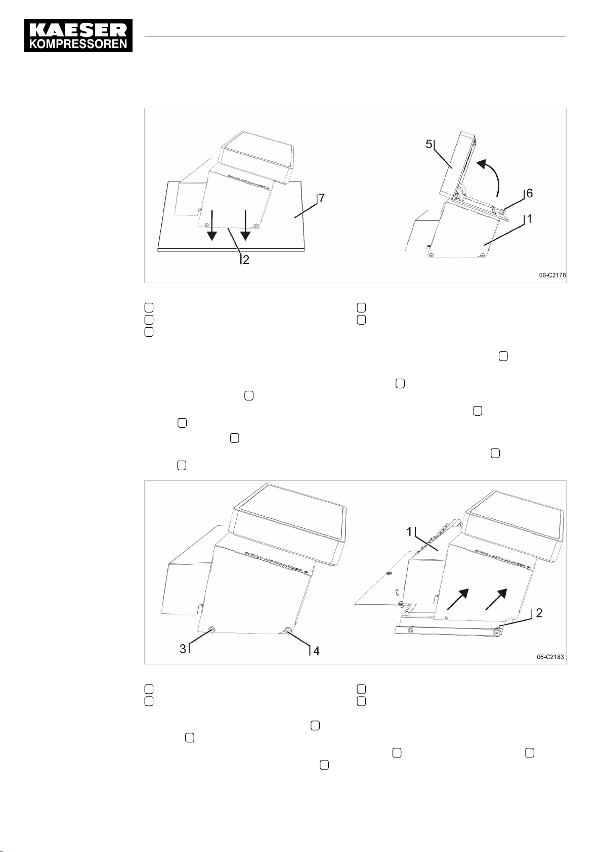
6 Installation
6.6 Installing the control cabinet
Fig. 6 Open the SAM 2 cover
1 Control cabinet cover
2 Base plate
5 Cover with SAM 2 terminal
6 Spagnolet
7 Base
1. Carefully unpack the control cabinet. Protect the sensitive surfaces (e.g., cover 5 with touch
screen terminal) from damage.
2. Place the entire control cabinet onto a suitable surface 7 (protected from dirt and scratching)
with the base plate 2 pointing downward.
3. Use the control cabinet key (two-way key, 3 mm) to unlock the spagnolet 6 at the control cabi‐
net 1 .
4. Open the cover 5 (in arrow direction).
5. Remove the cables which are connected from the modules on the base plate 2 with the termi‐
nal 5 .
32
Fig. 7 Removing the control cabinet cover
1 Control cabinet cover
2 Base plate
6. Separate the control cabinet cover 1 (enclosure cover with SAM 2 terminal) from the base
plate 2 as follows.
7. First, use the SW4 wrench to unscrew the two screws 3 , then loosen the two screws 4 and
carefully lift the control cabinet cover 1 in arrow direction (see Fig. 7).
Service manual SIGMA AIR MANAGEMENT SYSTEM
SAM 2 No.: 901735 00 E
3 Flat mushroom-head screw M 6x16, SW4
4 Flat mushroom-head screw M 6x16, SW4
Page 43
6 Installation
6.7 Identifying the machines
8. Place the control cabinet cover 1 onto a suitable surface 7 (protected from dirt and scratch‐
ing).
9. Properly attach the base plate 2 to the wall. A template for the bore holes is provided in the
annex (see chapter 13.1).
10. Wire the control cabinet as described in chapter 6.11.
6.7 Identifying the machines
Same model machines have to be identified as well, because the internal pressure regulation
can be set differently.
➤ Clearly identify or number the machines.
The alarm and service messages displayed on SAM 2 can thus be allocated to the correct ma‐
chine.
Identification (machine and SAM 2 ) for remote control
The machines and SAM 2 must carry a warning notice when they are in remote mode.
■ Warning notice to indicate the machines.
─ "WARNING": This machine is remotely controlled and can start automatically at any
time.
■ Warning notices for identification at SAM 2 .
─ Before starting, make sure that no one is working on the machines and that they can
be started safely.
Place the notices so they are highly visible.
1. Place warning notices on the machine.
2. Attach a warning notice at SAM 2 .
6.8 Connecting the pressure transducer
Precondition The connection point is not under pressure.
NOTICE
Network pressure too high
Damage to the pressure transducer
➤ Never connect the pressure transducer to a pressurised network with a maximum pres‐
sure exceeding the nominal pressure of the pressure transducer.
No.: 901735 00 E
1. Check the maximum working pressure of the compressed air network.
2. Check the nominal pressure of the pressure transducer.
6.8.1 Mechanical connection
The "pressure transducer position" graphic (illustration 8) shows the correct position for the trans‐
ducer:
Service manual SIGMA AIR MANAGEMENT SYSTEM
SAM 2
33
Page 44
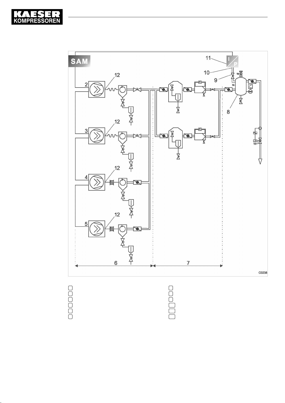
6 Installation
6.8 Connecting the pressure transducer
34
Fig. 8 Pressure transducer position
1 SAM 2
2 Machine 1
3 Machine 2
4 Machine 3
5 Machine 4
6 Compressed air generation
Service manual SIGMA AIR MANAGEMENT SYSTEM
SAM 2 No.: 901735 00 E
7 Air Treatment
8 Air receiver
9 Shut-off valve
10 Pressure transducer connection point
11 Pressure transducer
12 Maine compresses air outlet
Page 45
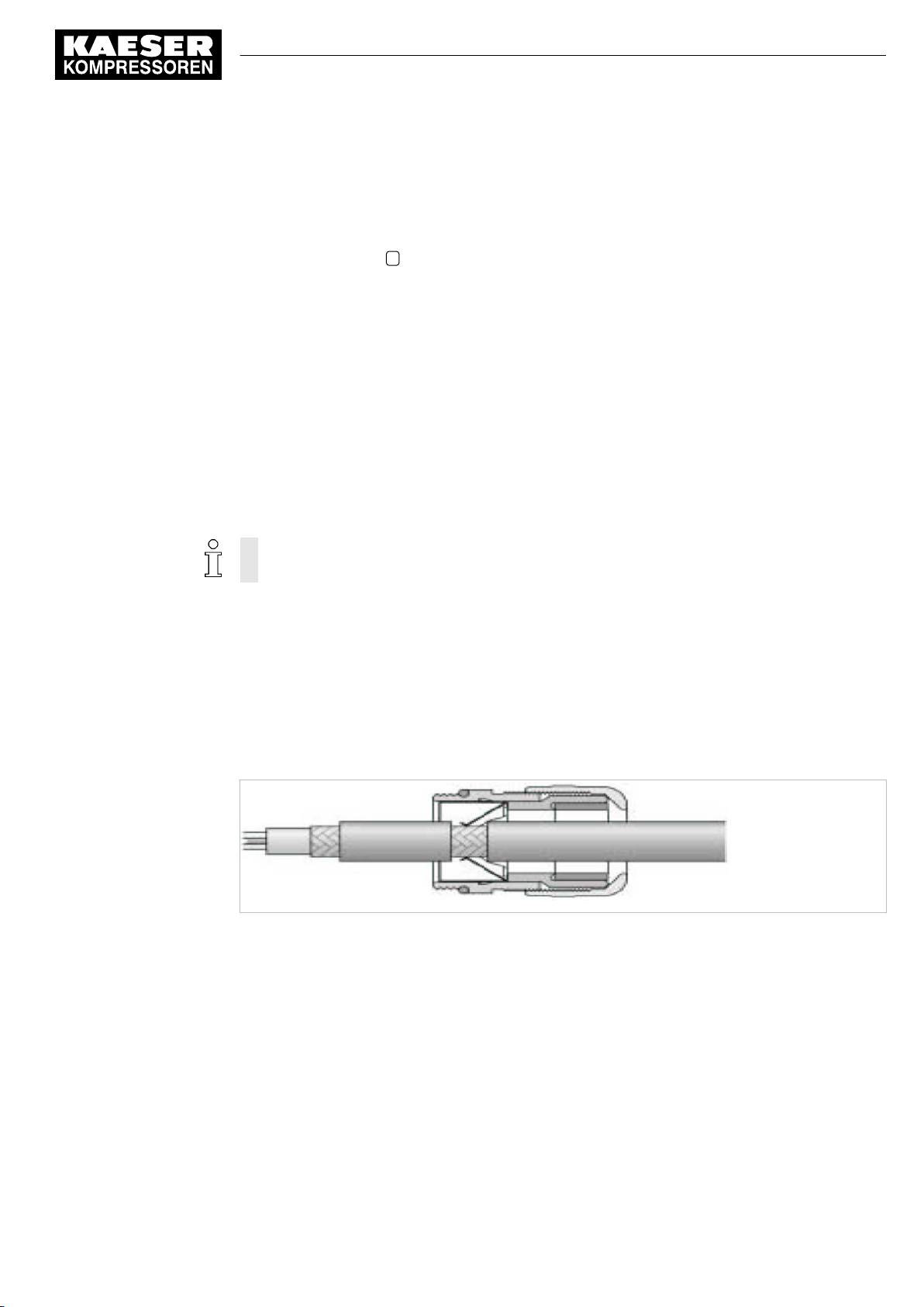
6 Installation
6.9 Planning the wiring
➤ Note the following when connecting the pressure transducer:
■ Connect the pressure transducer either to the side or the top of the air receiver so that no
condensate can settle.
■ If the pressure transducer is connected to the main collector pipe, fit a small, additional air
receiver (item 8 order separately, see chapter 13.6 for the material number).
■ Fit the pressure transducer downstream of the air treatment components because pres‐
sure losses caused by air treatment components or pipework can occur between the ma‐
chine and the point of measurement.
■ The airflow at the point of measurement must not pulsate.
■ Note the installation depth of the pressure transducer.
■ Install a shut-off valve between the air receiver and the pressure transducer. This allows
replacement of the pressure transducer without having to vent the air receiver. Ensure that
the shut-off valve cannot be closed during operation.
■ A kit of parts for the air connection is available separately (see chapter 13.6 for the materi‐
al number).
6.8.2 Electrical connection
Avoid signal distortion by uusingg suitable wiring and screening.
1.
Use two conductor screened cable with minimum section 0.75 mm2.
2. The pressure transducer must be earthed.
■ Earth by metallic contact with the air receiver or
■
Use a separate equipotential bonding conductor with a minimum cross-section 1 x 10 mm
(with, for example, an earth clamp (G 3/4) on the transducer housing).
3. Connect SAM 2 and the pressure transducer at the same equipotential bonding conductor. The
potential difference between both earthing points must be zero.
4. Connect the conductor screen at the pressure transducer to earth.
Fig. 9 Connecting the screening
2
C0246
No.: 901735 00 E
5. Feed the conductor through an EMC cable gland into the control cabinet.
6. Maintain a distance of at least 10 cm between the connecting cable and power cables.
6.9 Planning the wiring
There are several methods of linking the machines to SAM 2 or SBU :
■ Using SIGMA NETWORK
(for machines with SIGMA CONTROL 2 ), see chapter 6.10.1.
Prerequisites: A SIGMA NETWORK port is provided for every machine.
Service manual SIGMA AIR MANAGEMENT SYSTEM
SAM 2
35
Page 46
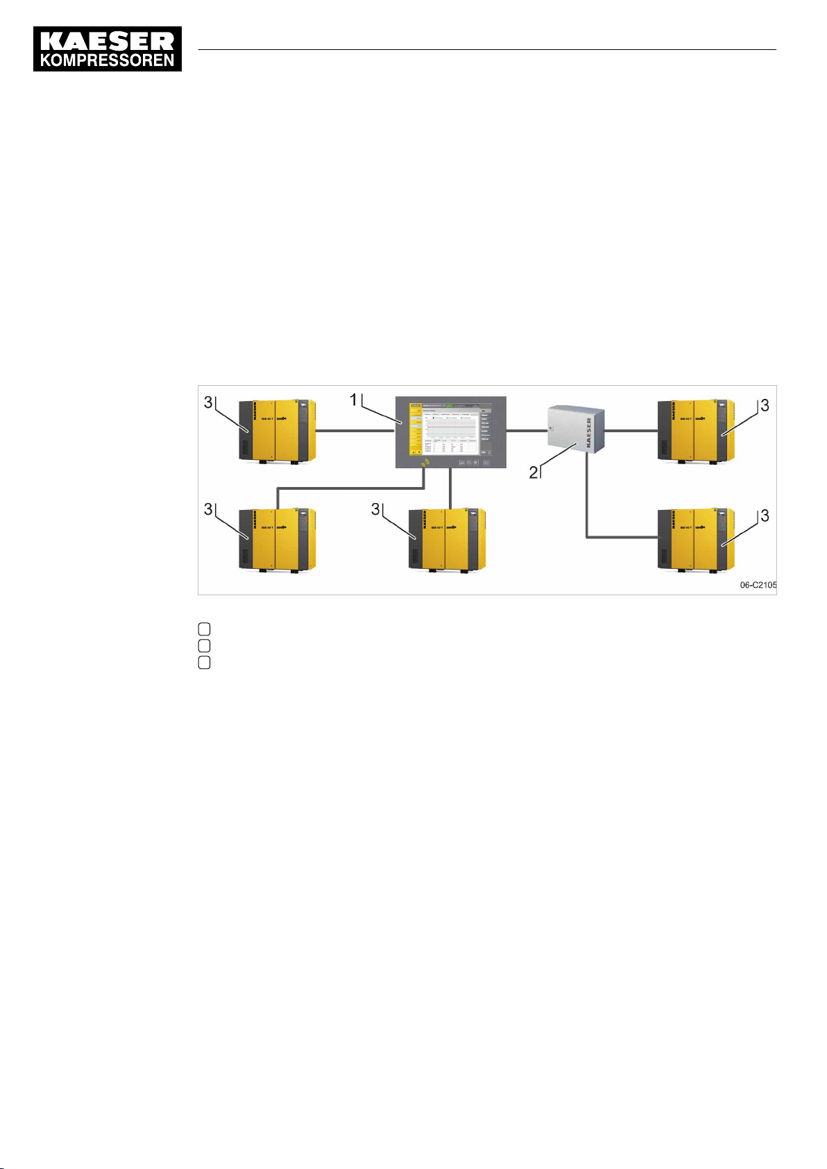
6 Installation
6.9 Planning the wiring
■ PROFIBUS
(when replacing a SIGMA AIR MANAGER with SAM 2 or for machines with
SIGMA CONTROL 2 ), see chapter 6.10.2.
Prerequisites: The PROFIBUS master option is available.
■ Using floating relay contacts
(for conventional machines without SIGMA CONTROL or SIGMA CONTROL 2 ; see chap‐
ter 6.10.3).
Prerequisites: At least one I/O Port DI and DOR is available for every machine.
6.9.1 SIGMA NETWORK
The SIGMA NETWORK subscribers are linked in a star pattern. All SIGMA NETWORK wires start
from SIGMA NETWORK hub installed in SAM 2 or SBU .
Fig. 10 SIGMA NETWORK design
1 SAM 2
2 SBU with option SIGMA NETWORK ports
3 Machine with SIGMA CONTROL 2
6.9.2 PROFIBUS network
PROFIBUS wiring is used when a SIGMA AIR MANAGER is replaced by SAM 2 in machines with
SIGMA CONTROL or SIGMA CONTROL 2 with a PROFIBUS communication module.
ThePROFIBUS subscribers are connected in series, that is, one after another. SAM 2 or SBU are
located at the end of the bus.
A terminating resistor can be activated in every PROFIBUS plug. At the start and at the end of the
bus cable, this resistor must be set to ON. In all other PROFIBUS plugs within the network, you
must set the terminating resistors to OFF.
36
Service manual SIGMA AIR MANAGEMENT SYSTEM
SAM 2 No.: 901735 00 E
Page 47
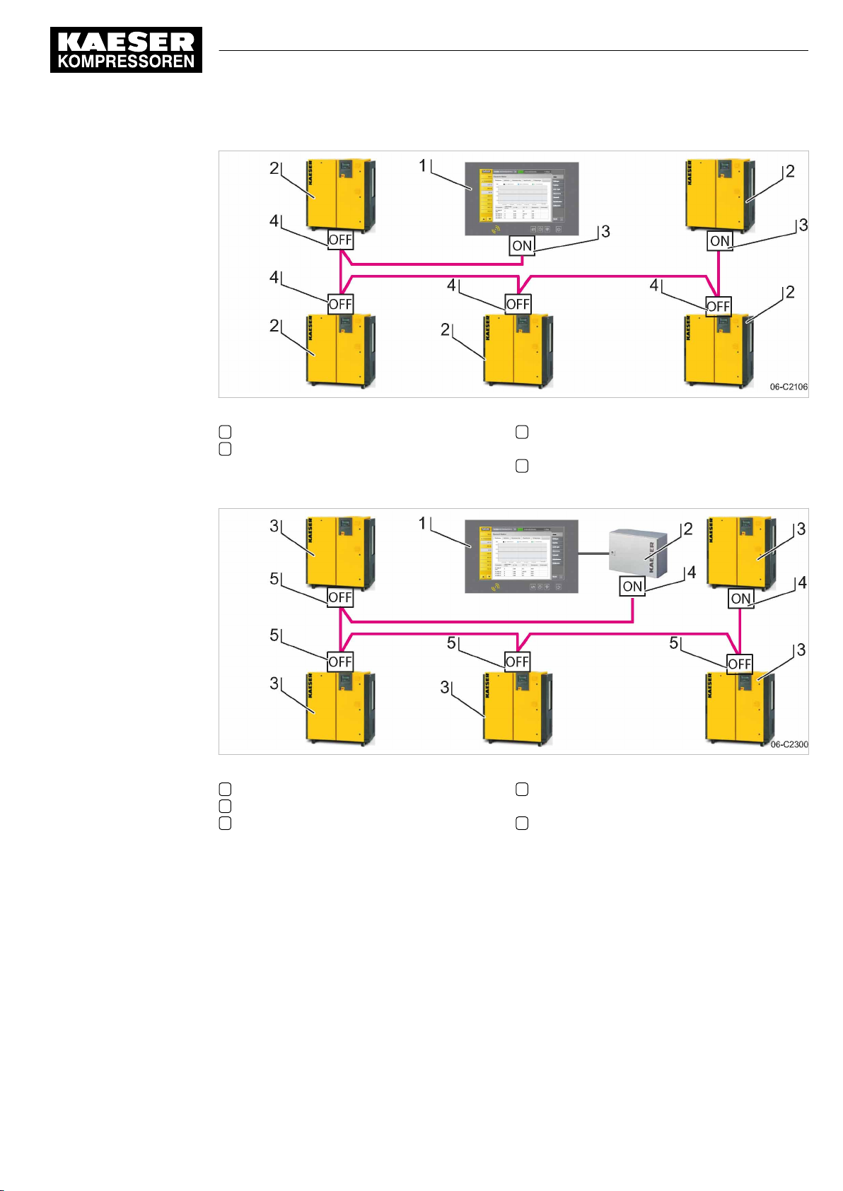
6 Installation
6.9 Planning the wiring
Fig. 11 Structure of a PROFIBUS network – SAM 2 with Option E1: PROFIBUS master
1 SAM 2
2 Machine with SIGMA CONTROL or
SIGMA CONTROL 2
3 PROFIBUS plug with terminating resistor
position: ON
4 PROFIBUS plug with terminating resistor
position: OFF
No.: 901735 00 E
Fig. 12 Structure of a PROFIBUS network – SBU with Option E1: PROFIBUS master
1 SAM 2
2 SBU
3 Machine with SIGMA CONTROL or
SIGMA CONTROL 2
4 PROFIBUS plug with terminating resistor
position: ON
5 PROFIBUS plug with terminating resistor
position: OFF
6.9.3 Floating contacts
The connection of conventional machines without SIGMA CONTROL or SIGMA CONTROL 2 via
floating contacts is realised in star pattern, that is, each machine is directly connected to SAM 2 or
SBU if more I/O conductors are required.
Service manual SIGMA AIR MANAGEMENT SYSTEM
SAM 2
37
Page 48
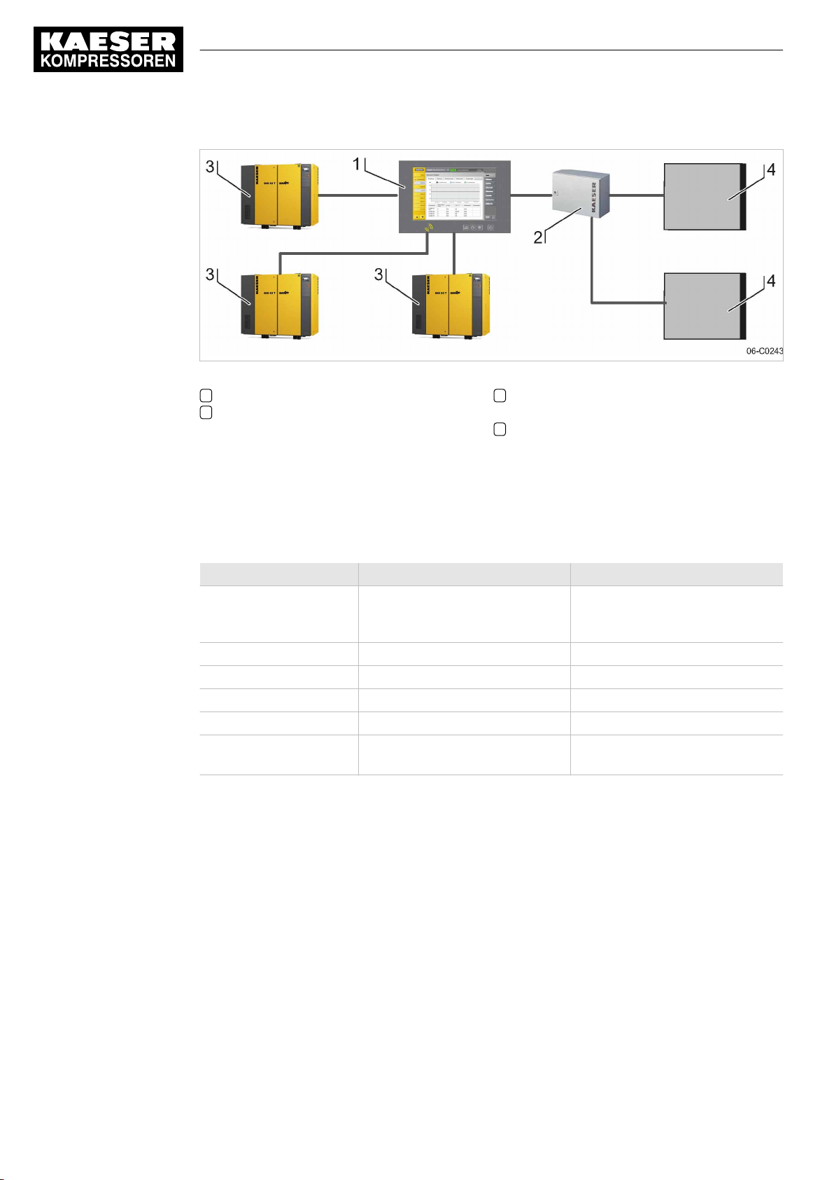
6 Installation
6.9 Planning the wiring
Fig. 13 Configuration of the network with floating relay contacts
1 SAM 2
2 SBU
3 Machine with SIGMA CONTROL or
4 Machine connected via floating relay con‐
SIGMA CONTROL 2
tacts
6.9.4 Instructions on the electrical installation
■ A supply disconnecting device to EN 60204 must be installed by the user.
■ Do not exceed the following maximal values for the cable lengths:
Model Maximum cable length [m] Remark
SIGMA NETWORK 100 Maximum cable length between
Digital transistor outputs 30
Digital relay outputs 100
Digital inputs 30
Analogue inputs 30 screened
PROFIBUS 800 Maximum cable length of the en‐
Tab. 28 Maximum cable lengths
■ Use galvanic isolation on cables laid outside the building to ensure increased lightning protec‐
tion (preferably fibre optic cable).
■ See chapter 2 for conductor types and cross-sections and the wiring diagram in chapter 13.8
for cable selection. We recommend to use flexible stranded wires wherever possible.
■ This suppressor is suitable for inductive loads connected to the relay outputs.
two SIGMA NETWORK compo‐
nents.
tire PROFIBUS.
38
6.9.5 Prerequisites and accessories required for connection with SIGMA NETWORK
Prerequisites: For each SIGMA NETWORK device ( SIGMA CONTROL 2 machine, SBU ) a
SIGMA NETWORK port is provided.
Service manual SIGMA AIR MANAGEMENT SYSTEM
SAM 2 No.: 901735 00 E
Page 49
6 Installation
6.9 Planning the wiring
The following accessories are required for the construction of a SIGMA NETWORK (see annex for
material numbers):
■ SIGMA NETWORK cable.
■ For SAM 2 : One RJ45 bus connector for every SIGMA NETWORK to be connected.
■ For SBU : One RJ45 bus connector for every SIGMA NETWORK to be connected.
■ For every SIGMA CONTROL 2 machine: LAN RJ45 retrofit kit.
6.9.6 Prerequisites and accessories connection with PROFIBUS
Prerequisites: PROFIBUS master option
When replacing a SIGMA AIR MANAGER with a SAM 2 , you can connect the existing
PROFIBUS to SAM 2 without additional equipment.
The following accessories are required for the wiring machines to SIGMA CONTROL 2 (see annex
for material numbers):
■ PROFIBUS cable
■ For SAM 2 or SBU : PROFIBUS connector
■ For every machine with SIGMA CONTROL: PROFIBUS plug set for SIGMA CONTROL
6.9.7 Requirements for connecting with floating relay contacts
Connect a floating output from SAM 2 or SBU in series with the existing pressure regulation
(main pressure switch or electronic pressure regulation) of the machine.
Avoid overload of the electric supply caused by simultaneous starting of compressors con‐
nected by floating relay contacts. You can stagger the start times by installing a timing relay
in some compressors.
In stations with EMERGENCY operation, compressors connected via floating relay contacts
will start when the compressor pressure is below the compressor's cut-in pressure and one of
the following conditions is met:
■ The voltage supply at SAM 2 and the compressor fails and returns simultaneously.
■ The voltage supply at SAM 2 fails but not at the compressor.
■ SAM 2 fails.
Required equipment for machines to be connected to SAM 2
SAM 2 design Equipment
Up to 4 machines are connected via floating relays contacts to SAM 2 or SBU :
SAM 2-4/SAM 2-8 An "external load control" input.
An additional "motor running" floating relay contact (normally open) is recom‐
mended.
More than 4 machines are connected via floating relays contacts to SAM 2 or SBU :
No.: 901735 00 E
Service manual SIGMA AIR MANAGEMENT SYSTEM
SAM 2
39
Page 50
6 Installation
6.10 Laying cables
SAM 2 design Equipment
SAM 2-16 A "manual/automatic mode" / "LOAD/IDLE" control input with a system pres‐
Tab. 29 Required equipment
If a machine is not prepared for connection to SAM 2 , it can be retrofitted. Documents and parts
for the retrofit are available separately.
6.10 Laying cables
sure switch in manual mode (-B1.1).
A "pressure switch in series with SAM 2 ” (-B1) or a pressure switch blow-off
protection pressure reliaf valve (-B6).
A "motor running" floating relay contact (normally open).
A "ON and no alarm" floating relay contact (normally open).
DANGER
Contact with live electric components can cause serious injury or death.
➤ De-energise SAM 2 / SBU and external power sources.
1. Switch off all phases of SAM 2 / SBU and external power sources.
2. Lock against reactivation.
3. Observe all accepted safety regulations and national legislation applicable to all work carried
out on the SAM 2 / SBU .
4. Have SAM 2 / SBU connected to the power supply by an authorised and qualified electrician to
national legislation and the regulations of the electricity company concerned.
The terminals of SAM 2 / SBU must be identified with one of the following alternatives as they
may carry voltage even when the power supply is shut off.
■ Orange
■ Label
5. Create the connections to the power supply, the individual machines and the component as
detailed in the circuit diagrams.
6.10.1 Creating SIGMA NETWORK
1. Lay SIGMA NETWORK cables.
■ For details to create SIGMA NETWORK , see Fig. 10.
■ For details of the connection at the machine, see the description for "LAN retrofit kit
SIGMA CONTROL 2 ".
■ For details of the connection at SAM 2 or SBU , see chapter 6.11.
2. For maximal cable lengths, see chapter 6, "Notes to the electrical installation".
40
Service manual SIGMA AIR MANAGEMENT SYSTEM
SAM 2 No.: 901735 00 E
Page 51
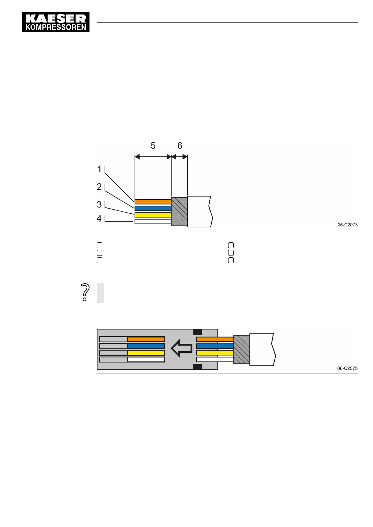
6 Installation
6.10 Laying cables
6.10.1.1 Installing the RJ45 bus connector
To connect to SIGMA NETWORK , you must connect the network subscribers according to the
SIGMA NETWORK conduit.
■ Feed the network cable to the SIGMA NETWORK devices on both sides through one EMC
screw fitting.
■ Use an RJ45 bus connector at both ends of the network cable.
Installing the RJ plug
Fig. 14 Strip the isolation from the network cable.
1 Orange
2 Blue
3 Yellow
1. Stripping the network cable isolation (see Fig. 14).
The RJ45 plug and the network cable can be damaged if unlocked under strain.
➤ Always release strain on the RF45 plug prior to unlocking.
2. Spread the conductors according to the colour coding of the contact element of the RJ45 con‐
nector (see Fig. 14).
Fig. 15 Inserting the network cable conductors
3. Insert the conductors into the contact elements up to the end stop.
4 White
5 18 mm
6 5 mm
No.: 901735 00 E
Service manual SIGMA AIR MANAGEMENT SYSTEM
SAM 2
41
Page 52
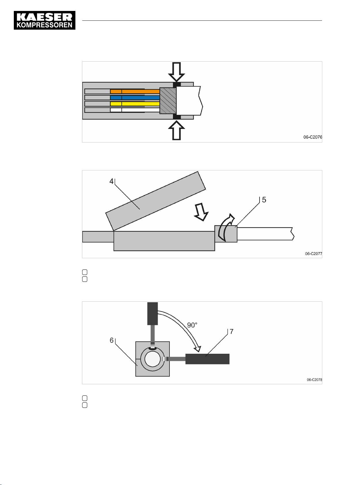
6 Installation
6.10 Laying cables
Fig. 16 Positioning the network cable
4. Position the network cable as shown (arrows, see Fig. 16).
Fig. 17 Close the lid of the RJ45 plug.
4 RJ45 plug lid
5 Rotatable locking piece
5. Close the lid and manually rotate the locking piece clockwise as far as possible.
Fig. 18 Rotating the locking piece to the stop
6 RJ45 plug (view from cable end)
7 Screwdriver
42
Service manual SIGMA AIR MANAGEMENT SYSTEM
SAM 2 No.: 901735 00 E
Page 53
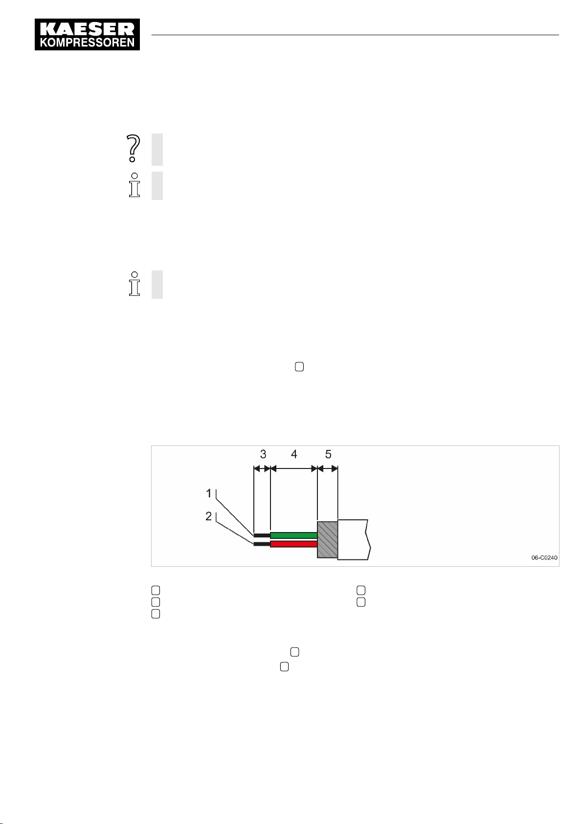
6 Installation
6.10 Laying cables
6. Insert a screwdriver with 2.5 mm blade width into the bore and rotate the locking piece clock‐
wise up to the end stop.
Contact issues with conductor ends after multiple contact creation.
➤ Cut off contacted conductor ends and again strip the conductors.
The insulation displacement contacts of the plug may be disconnected and re-contacted up
to 10 times.
Result The plug is correctly locked when the opening of the locking piece is facing sideways and the side
surfaces are flush with the plug.
6.10.2 Creating the PROFIBUS network
When replacing a SIGMA AIR MANAGER with a SAM 2 , you can connect the existing
PROFIBUS to the SAM 2 .
1. Install PROFIBUS cables.
■ See Fig. 11 for details about the creation of a PROFIBUS network.
■ See the installation instructions for the "PROFIBUS retrofit kit“ for details about the ma‐
chine integration.
2. Switch the terminating resistor 3 (see Fig. 11) at both ends of the PROFIBUS to the ON posi‐
tion.
3. See the wiring diagrams in the annex for cable types, cross-sections and maximum cable
lengths.
6.10.2.1 Connecting the PROFIBUS cable
Fig. 19 Stripping the isolation from the PROFIBUS cable
1 Green conductor
2 Red conductor
3 5 mm
1. Strip the isolation from the PROFIBUS cable as shown.
2. Connect the green conductor 1 to the green terminal “A” of the PROFIBUS plug.
3. Connect the red conductor 2 to the red terminal “B” of the PROFIBUS plug.
4 13 mm
5 6 mm
No.: 901735 00 E
Service manual SIGMA AIR MANAGEMENT SYSTEM
SAM 2
43
Page 54
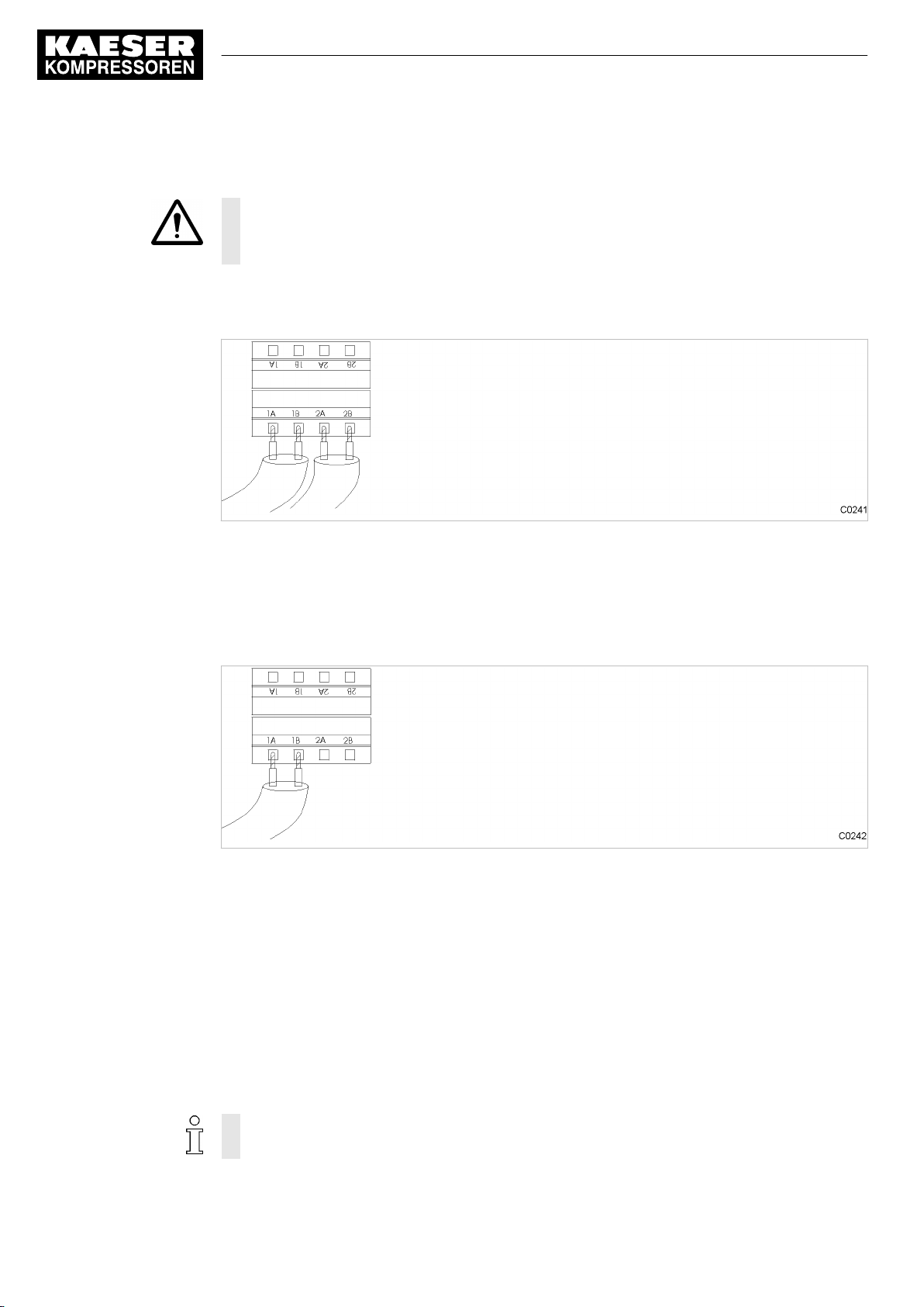
6 Installation
6.10 Laying cables
6.10.2.2 Installing the PROFIBUS plug
NOTICE
Too tight a bend radius can cause a defect in the PROFIBUS cables.
➤ Do not bend the PROFIBUS cable.
Subscribers in the middle of a PROFIBUS network:
Install the PROFIBUS plug at one of the inline subscribers to the PROFIBUS network:
Fig. 20 Connection of an inline plug
1. Connect two PROFIBUS cables (input and output)
2. Set the terminating resistor in the PROFIBUS plug to OFF.
Subscribers at the end of the PROFIBUS network
Install the PROFIBUS plug at a terminating subscriber and at the SAM 2 :
Fig. 21 Installation of a terminating PROFIBUS plug
1. Connect one PROFIBUS cable (input only).
2. Set the terminating resistor in the PROFIBUS plug to ON.
6.10.3 Creating the compressor station via floating relay contacts
44
1. Use conventional wiring.
■ For details of creating a network with floating relay contacts, see Fig. 13.
2. Directly connect each machine with SAM 2 or SBU .
6.10.3.1 Wiring modifications to the machine
Interruptions to the air supply caused by unsuppressed inductive loads connected to the relay
outputs of SAM 2 or SBU , such as auxiliary contactors or solenoid valves.
Service manual SIGMA AIR MANAGEMENT SYSTEM
SAM 2 No.: 901735 00 E
Page 55
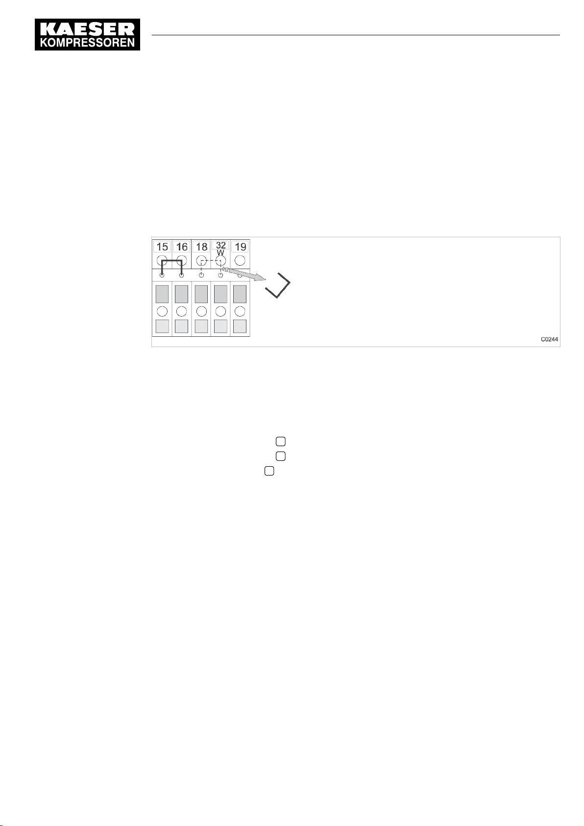
6 Installation
6.11 Connecting lines
1. Suppress inductive loads with an RC interference suppressor.
2. Connect the interference suppressor in parallel directly at the coil (connections A1–A2). If the
connections are inaccessible, in solenoid valves for example, the suppressor can also be con‐
nected to the corresponding terminals on the terminal strip.
3. Use an RC interference suppressor suited to the coil voltage and apparent holding power, see
chapter 13.6.
Machine with "external load signal" control input
KAESER machines from 1990 onwards with terminal 32W:
Fig. 22 Remove the wire jumper.
➤ Remove the jumper between the terminals (terminals 32W and 21 or 18) to allow sequencing.
Machines without terminal 32W
1. Fit terminal 32W in the terminal strip.
2. Disconnect the conductor A of the mains pressure switch cable connected to terminal 18.
3. Disconnect the conductor A of the mains pressure switch cable connected to terminal 21.
4. Connect the conductor A to terminal 32W.
6.10.3.2 Machine with one control input for "Operating mode Manual/Automatic" / LOAD/IDLE
KAESER machines from1990 onwards:
If a jumper is connected between the terminals for manual operation [-X1 (W) 20 or 17 and X1 (W) 24 (W)] on the terminal strip for connection of SAM 2 or SBU , then it must be removed. A
more precise designation of the terminals is given in the electrical diagrams for the machine.
➤ Remove wire jumper if necessary.
6.11 Connecting lines
6.11.1 Wiring the control cabinet
Precondition The control cabinet is properly attached to the wall as described in chapter 6.6.
No.: 901735 00 E
The base plate is freely accessible.
➤ Wire the control cabinet as described below.
Service manual SIGMA AIR MANAGEMENT SYSTEM
SAM 2
45
Page 56
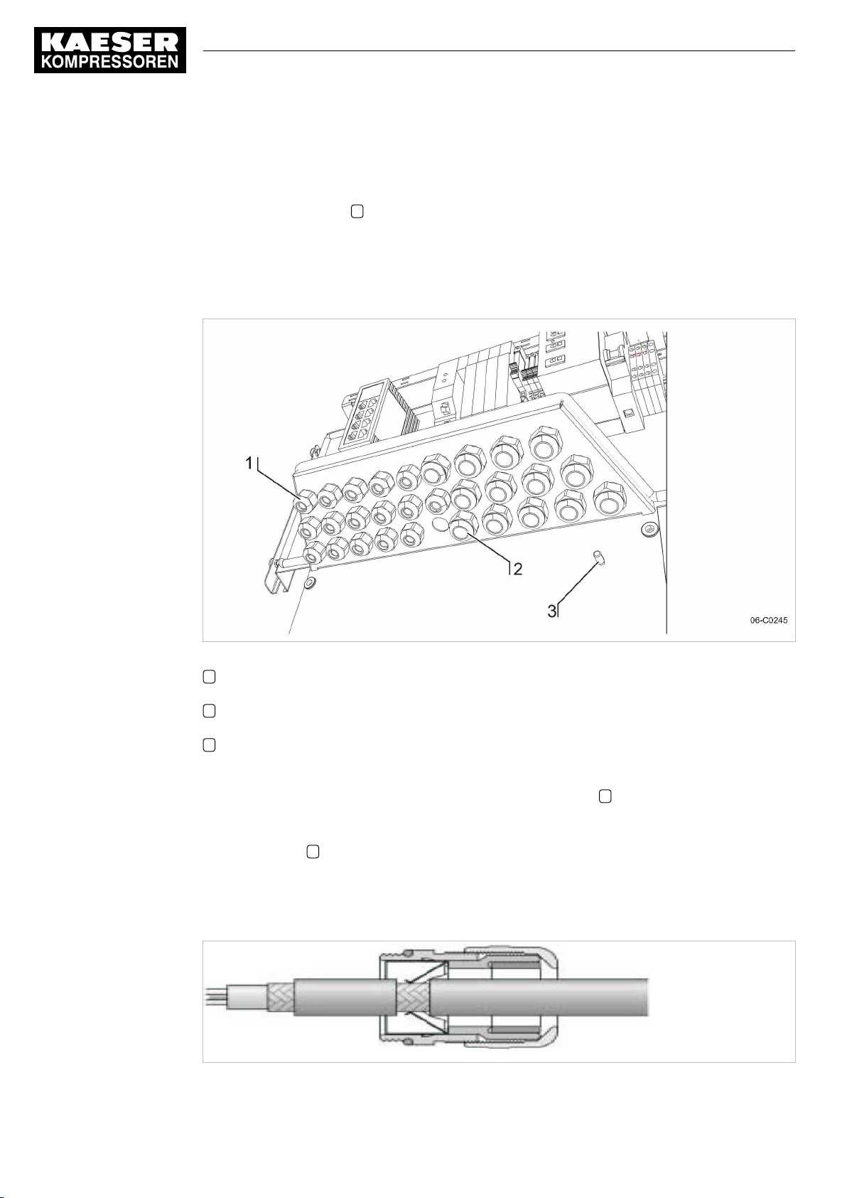
6 Installation
6.11 Connecting lines
6.11.2 Connecting the equipotential bond
1. Connect the enclosure with a user-supplied equipotential bond at the corresponding equipoten‐
tial bond connection 3 .
2. Keep the connection as short as possible.
3.
Use an earth strap or cable with a cross-section of at least 16 mm2.
6.11.3 Feeding cables and connecting the screening
Fig. 23 Cable glands with and without ferrite suppressors
1 Metallic cable glands for screened cables (analogue inputs, SIGMA NETWORK ,
PROFIBUS, cables to the COM module and the user's LAN)
2 Plastic cable glands for unscreened cables (common supply line, digital inputs, digital out‐
puts)
3 Equipotential bond connection (stud)
1. Feed screened cables (analogue inputs, SIGMA NETWORK , PROFIBUS, cables to the COM
module and the user's LAN) through the metallic cable glands 1 . Connect the screening as
described below.
2. Feed unscreened cables (common supply line, digital inputs, digital outputs) through the plastic
cable glands 2 .
Connecting the screening
At the control cabinet:
C0246
46
Fig. 24 Connecting the screening
Service manual SIGMA AIR MANAGEMENT SYSTEM
SAM 2 No.: 901735 00 E
Page 57
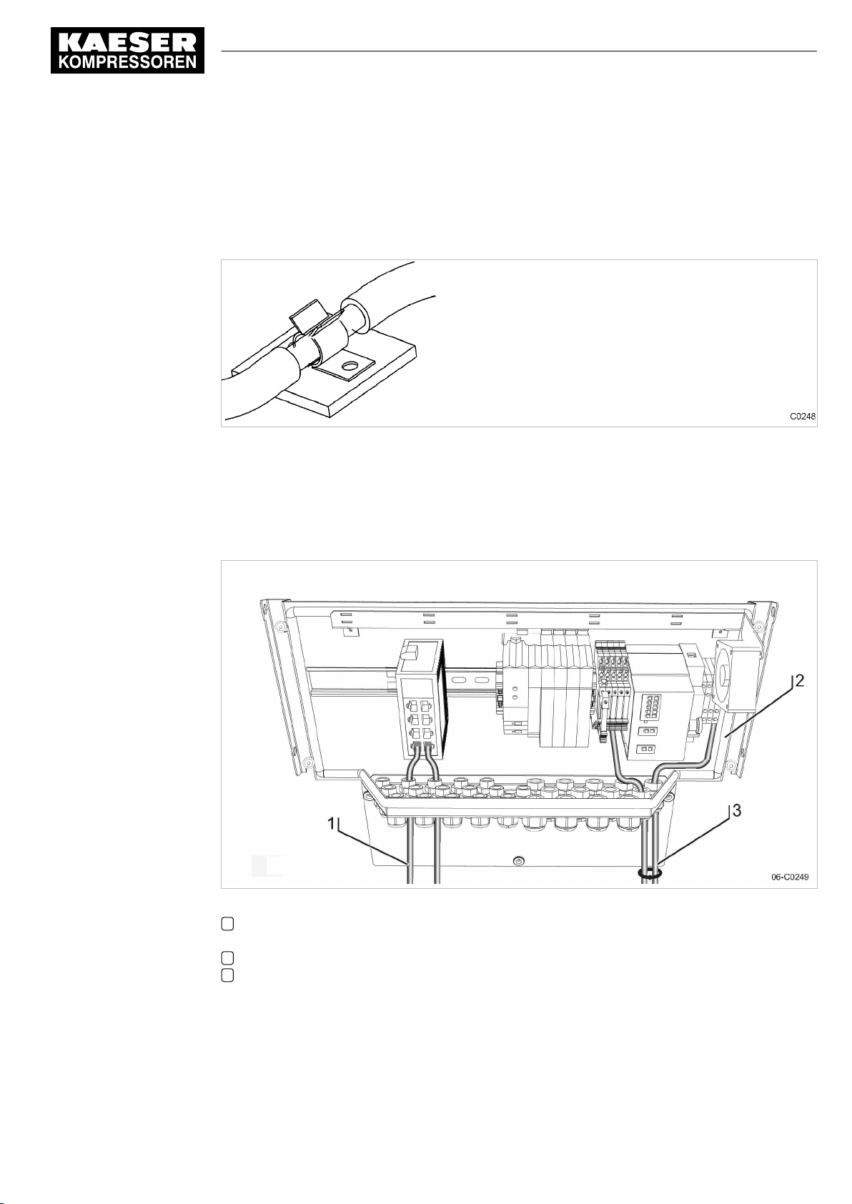
6 Installation
6.11 Connecting lines
1. Strip off the cable insulation by about 1 cm where the cable passes through the cable gland.
2. Push the cable through the metal cable gland on the control cabinet until the stripped section
snaps in and contacts the earth clamp in the cable gland.
Connecting the screening for the user's LAN
Fig. 25 LAN conduit screening
1. Strip off the cable insulation by about 1 cm at the terminal.
2. Ensure electrical contact of the cable screening with the screening clamp.
6.11.4 Laying the cables in the control cabinet
No.: 901735 00 E
Fig. 26 Laying the cables in the control cabinet
1 Cables with voltages up to 24 V (digital inputs, analogue inputs, SIGMA NETWORK ,
PROFIBUS, cables to the COM module and the user's LAN, relay outputs, if provided)
2 SAM 2 control cabinet
3 Cables with 115/230 V AC voltage (common supply line, relay outputs, if provided)
1. Use cable ties to bundle all 115/230 V AC cables and keep them separate from all other ca‐
bles.
2. Install the bus cables to the SAM 2 terminal so that they will not be kinked by opening and
closing the cover.
Service manual SIGMA AIR MANAGEMENT SYSTEM
SAM 2
47
Page 58
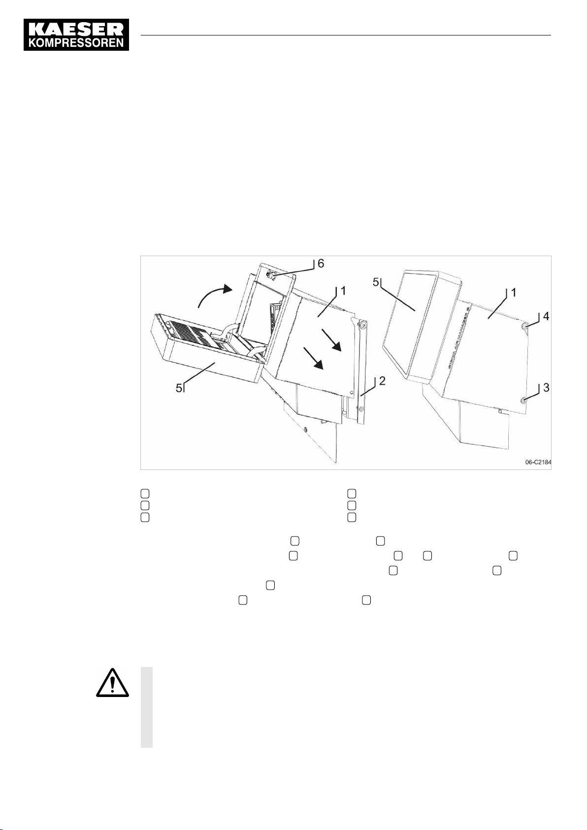
6 Installation
6.12 Setting up the machines
6.11.5 Connecting the cables
1. Make the connections to terminals and interfaces as detailed in the attached wiring diagram.
2. Connect external sensors according to the wiring diagram in the annex.
3. For installing the RJ45 bus connector, see chapter 6.10.1.
4. For installing the the PROFIBUS plug, see chapter 6.10.2.
6.11.6 Installing the control cabinet
Precondition The base plate of the control cabinet is properly attached to the wall (see chapter 6.6).
The control cabinet is fully wired (see chapter 6.11.1).
Fig. 27 Installing the control cabinet
1 Control cabinet cover
2 Base plate
3 Screw M 6x16, SW4
1. Mount the control cabinet cover 1 on the base plate 2 .
2. Install the control cabinet cover 1 , using the four screws 3 and 4 on the base plate 2 .
3. Connect the internal cables leading from the base plate 2 to the SAM 2 terminal 5 .
4. Close the SAM 2 terminal 5 .
5. Lock the spagnolet 6 at the control cabinet cover 1 with the control cabinet key (two-way type,
3 mm).
6.12 Setting up the machines
NOTICE
Damage to drive motors can occur when the permissible motor starting frequency is excee‐
ded on machines without idle control (piston compressors, blowers).
➤ Set the SAM 2 pressure band to a width which ensures that the switching frequency is
not exceeded.
➤ If necessary, increase the capacity of the air receiver.
4 Screw M 6x16, SW4
5 SAM 2 terminal
6 Spagnolet
48
Service manual SIGMA AIR MANAGEMENT SYSTEM
SAM 2 No.: 901735 00 E
Page 59
6 Installation
6.12 Setting up the machines
Precondition The settings described in this section must be entered in full for every machine to ensure faultless
operation. Make sure that the compressed air system remains in operation should the SAM 2 fail.
➤ Carry out settings as detailed in this manual.
6.12.1 Integration with SIGMA NETWORK
The prescribed procedure for the setting of SIGMA CONTROL 2 machines is described in the
corresponding operating manuals.
Only use the current software version for SIGMA CONTROL 2 .
Set the IP address of the network subscribers as follows:
SAM 2 : IP address = 169.254.100.“Machine number +100“
SAM 2 does not automatically assign the IP addresses to the network users. Either the wrong
machine or no machine at is controlled if an incorrect IP address is assigned.
1. Enter system pressure pB (p2 and set as default for "Manual mode pressure".
Simultaneous activation of the machines in manual mode
➤ In manual mode, the pressure set point of each machine should be staggered by 0,3 bar
to prevent all machines starting together. The stagger time for station operation must be
set. Suggestions for these settings are found in the annex (see chapter 13.5.2).
2. Activate and setting up automatic restart after a power failure.
3. Configure the operation at the SIGMA NETWORK .
6.12.2 Integration with PROFIBUS
The correct procedure for setting up SIGMA CONTROL machines is described in the corre‐
sponding operating manuals.
Note the settings made in the appropriate form in the attachment.
Set the slave numbers of the PROFIBUS devices as follows:
■ SIGMA CONTROL Slave No. = Machine number +2
■ SIGMA CONTROL 2 : Slave No. = Machine number +102
Either the wrong machine or no machine at is controlled if an incorrect slave number is en‐
tered.
1. Enter system pressure pB (p2 and set as default for "Manual mode pressure".
Simultaneous activation of the machines in manual mode
➤ In manual mode, the pressure set point of each machine should be staggered by 0,3 bar
to prevent all machines starting together. The stagger time for station operation must be
set. Suggestions for these settings are found in the annex (see chapter 13.5.2).
No.: 901735 00 E
2. Activate and setting up automatic restart after a power failure.
3. Configure PROFIBUS operation.
The following settings are recommended as parameters for bus alarms:
Parameter Value Meaning
Start td: 40.0 s Maximum period that the machine waits for a signal from the PROFIBUS after
return of the power supplies. If no signal arrives before the period ends, the
machine switches to self-control.
Service manual SIGMA AIR MANAGEMENT SYSTEM
SAM 2
49
Page 60
6 Installation
6.12 Setting up the machines
Parameter Value Meaning
Timeout 5.00 s Period after which the machine switches to self-control if a fault occurs in
SAM 2 .
Restart Auto Not at SIGMA CONTROL 2 .
The machine automatically connects again when the PROFIBUS runs again af‐
ter a bus alarm.
Restart man. Not at SIGMA CONTROL 2 .
After a bus alarm the machine remains under its own internal control until it is
connected to the bus again when the «remote» key is pressed.
Tab. 30 Parameter for bus alarm
4. Repeat steps 1 to 3 for any further machines.
6.12.3 Linking via floating relay contact
Precondition The machines are provided with the relay contacts required and they are wired up (see chap‐
ter 6.9.7).
➤ Note the settings made here in the table in the annex (see chapter 13.5)
Rotary screw compressors always have an EMERGENCY mode. Piston compressors and
blowers may or may not have this facility.
6.12.3.1 Stations with EMERGENCY mode facility
■ In automatic mode, SAM 2 assumes the LOAD / IDLE regulation.
■ In manual mode, the machines run under the control of their own internal pressure regulation.
Machine with "External load control" input
When the machine is linked, the machine pressure regulation (mains pressure switch (-B1) or elec‐
tronic pressure control) remains in operation. The system automatically runs in emergency mode
via these pressure switches if power to the SAM 2 fails or the SAM 2 itself malfunctions, ensuring a
further supply of compressed air.
➤ Set the pressure control.
Further information For more information about the suggested settings for the pressure control, see Annex, chap‐
ter 13.5.1.
50
Machine with one control input for "Operating mode Manual/Automatic" / LOAD/IDLE
A "blow off protection pressure relief valve" pressure switch (-B6) or a "pressure switch in series to
the SAM 2 load output" (-B1) is fitted in the machines to prevent one of the following:
■ The machine is overloaded
■ The pressure relief valve responds due to:
- switching points set too high
- defective master controller
- excessive pressure loss between the machine and the pressure transducer of SAM 2 .
Service manual SIGMA AIR MANAGEMENT SYSTEM
SAM 2 No.: 901735 00 E
Page 61

6 Installation
6.12 Setting up the machines
➤ Set the "pressure switch in series to the SAM 2 load output“ (-B1). See chapter 13.5.1 for rec‐
ommended settings.
➤ Set the "pressure switch for manual operation (-B1.1) in sequence to ensure that the machines
cut in after another. See chapter 13.5.2 in the Annex for recommended settings.
6.12.3.2 Stations without emergency mode capability
Blowers and reciprocating compressors are not fitted with a pressure switch that could ensure
EMERGENCY operation.
When these machines are connected, the IDLE switching is controlled by SAM 2 .
These stations will stop delivering compressed air if SAM 2 fails.
➤ Take suitable application-specific measures.
No.: 901735 00 E
Service manual SIGMA AIR MANAGEMENT SYSTEM
SAM 2
51
Page 62
7 Initial Start-up
7.1 Commissioning – overview
7 Initial Start-up
7.1 Commissioning – overview
SAM 2 has been designed and developed for a number of applications. The settings that can be
made are correspondingly varied.
When shipped, SAM 2 is preconfigured with a standard configuration. Generally, most of
these settings can be used for many applications or need only minor modifications. Thus, not
all the steps listed below may be required for the initial start-up. This depends on the applica‐
tion involved.
topic Description
Switch on SAM 2 Chapter 7.2 Switch on "SAM 2"
Setting the Language Chapter 7.3 "Language"
User log-on Chapter 7.4 "User log-on"
Setting the time zone, date and time Chapter 7.5 "Date and time"
Setting the Unit settings Chapter 7.6 "Unit settings"
Setting the E-Mail Chapter 7.7 "E-Mail"
Setting up the display Chapter 7.8 "Display"
Data recording Chapter 7.9 "Data recording"
SAM 2 Upgrade Chapter "Upgrade"
Peripherals Chapter 7.10 "Peripherals"
P+I diagram Chapter 7.11 "P+I diagram"
Control Chapter 7.12 "Control"
SAM 2.Logic Chapter "SAM 2.Logic"
Time control Chapter "Time control"
Process control Chapter "Process control"
Activating the controller Chapter 7.13 "Activating the controller"
52
Tab. 31 Commissioning – overview
7.2 Switching on SAM 2
Precondition Nobody works at the machines.
All maintenance doors and removable panels are properly installed, closed and secured.
All installation tasks and wiring as described in chapter 6 "Installation" are properly completed.
The ambient conditions as described in chapter 5 "Installation and Operating Conditions" are met.
1.
NOTICE!
There is risk of damage to the compressed air supply through premature changeover to auto‐
matic mode.
➤ Press Automatic mode only when all settings required for commissioning (see chapter
7 "Initial Start-up" ) have been made.
Service manual SIGMA AIR MANAGEMENT SYSTEM
SAM 2 No.: 901735 00 E
Page 63
7 Initial Start-up
7.3 Setting the language
2. Switch on the power supply for SAM 2 at the user's power supply isolating device.
SAM 2 starts. The machine is switched on when the "Main menu" appears (after 2 minutes ap‐
proximately).
Symbol Operating element Key illumination
Button remote control Green
Button time control Green
Button automatic Green
Button station On/Off Green/red
Tab. 32 Keys on the SAM 2 operating panel
3. Ensure that SAM 2 is set to
4. If the key illuminated green, press again this key for the illumination to extinguish.
■ Stations without EMERGENCY operation will not deliver compressed air (see chapter 6.4
"Installation" ).
■ In compressed air systems with EMERGENCY operation capability, the machines run un‐
der their own internal pressure control (see chapter 6.4 "Installation" ).
7.3 Setting the language
You can choose and set the user interface language for the SAM 2 .
1. Press Configuration ➙ Language .
The
Language
2. Touch the symbol.
The available languages are displayed in a list.
3. Select the desired "Language (country)" combination.
SAM 2 loads and automatically displays the selected language.
menu displays the currently set language.
7.4 User log-on
Together with your SAM 2 , you received two KAESER Equipment Cards. They authorise the user
to log on to SAM 2 and make or change settings.
Manual mode
mode. The key does not illuminate.
No.: 901735 00 E
The KAESER Equipment Cards provide various functionalities:
■ Switch between three operating modes:
─ Logged out
─ Monitoring
─ Operating
■ Encryption ensures security
■ Different access levels for the customer (Equipment Card) and Service (Key)
Service manual SIGMA AIR MANAGEMENT SYSTEM
SAM 2
53
Page 64
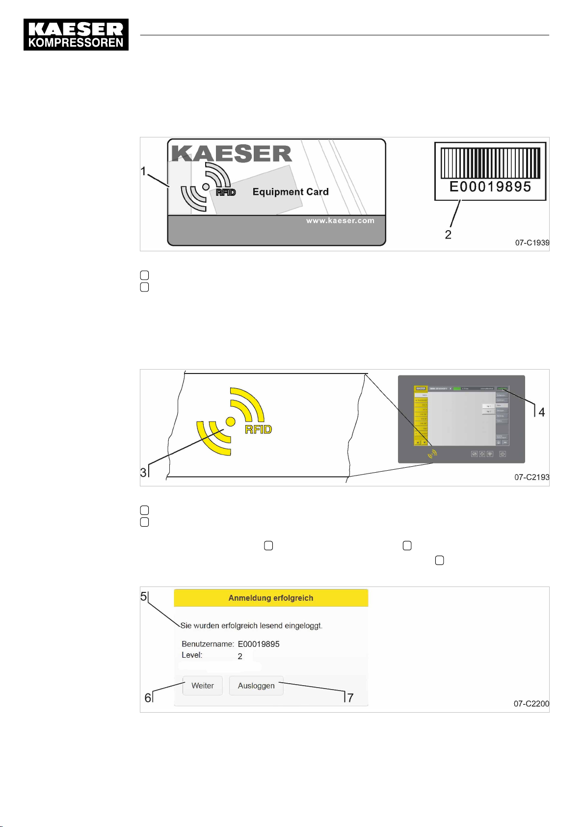
7 Initial Start-up
7.4 User log-on
The system records which user is when logged on at SAM 2 . You can thus determine who was
logged on when specific messages or other events have occurred.
Fig. 28 KAESER Equipment Card
1 KAESER Equipment Card
2 Number on the back of the KAESER Equipment Card
1. Remove the Equipment Card from the plastic sleeve.
2. Record the number shown on the back of the Equipment Card and keep it at a secure location.
7.4.1 Log on with Equipment Card
Fig. 29 RFID reader
3 RFID reader
4 ACCESS MODE menu element
1. Hold the Equipment Card 1 directly in front of RFID reader 3 . The log-on data are read.
If the system recognises the Equipment Card, it returns a message 5 . The message compri‐
ses information about User name and Access level .
54
Fig. 30 Logged on
Service manual SIGMA AIR MANAGEMENT SYSTEM
SAM 2 No.: 901735 00 E
Page 65
7 Initial Start-up
7.5 Date and time
2. Press Continue 6 to confirm the message.
The message window closes.
The user is now logged on with
menu element.
3. To switch to “ Operating “, repeat this procedure from Step 1.
The user is now logged on with
menu element.
7.4.2 User log-out
1. To kog out from the system, hold the Equipment Card 1 directly in front of the RFID reader 3 .
If the system recognises the Equipment Card, it returns a message 5 .
2. Press Logout 7 to log out.
The access level will automatically return to "Logged out" after 10 minutes without user inter‐
vention.
Monitoring
Operating
access level. This shown in the
access level. This shown in the
ACCESS MODE
ACCESS MODE
4
4
7.5 Date and time
You must set the time zone in which the SAM 2 is operated and the current date and time. This is
required to ensure proper functioning of the machine controller, messages, logs and evaluations.
Precondition Log on with access level 2: Operating (see chapter 7.4 "User log-on").
➤ Enter the settings in the sequence described below:
7.5.1 Setting the time zone
Set the time zone for the SAM 2 to ensure the timely automatic conversion from standard time to
daylight savings time, for example.
1. Press Configuration ➙ Date and time .
The
Date and time settings
2. Press the Time zone key.
3. Use the scroll wheel to move up or down to set the time zone. The display value in the centre
is saved as the setting.
Use the scroll wheel to move up or down to set the time zone for the device.
4. Press OK to apply the set time zone.
7.5.2 Setting date and time
1. Press Configuration ➙ Date and time .
The
Date and time settings
2. Press the Current key.
menu is displayed.
menu is displayed.
No.: 901735 00 E
Service manual SIGMA AIR MANAGEMENT SYSTEM
SAM 2
55
Page 66
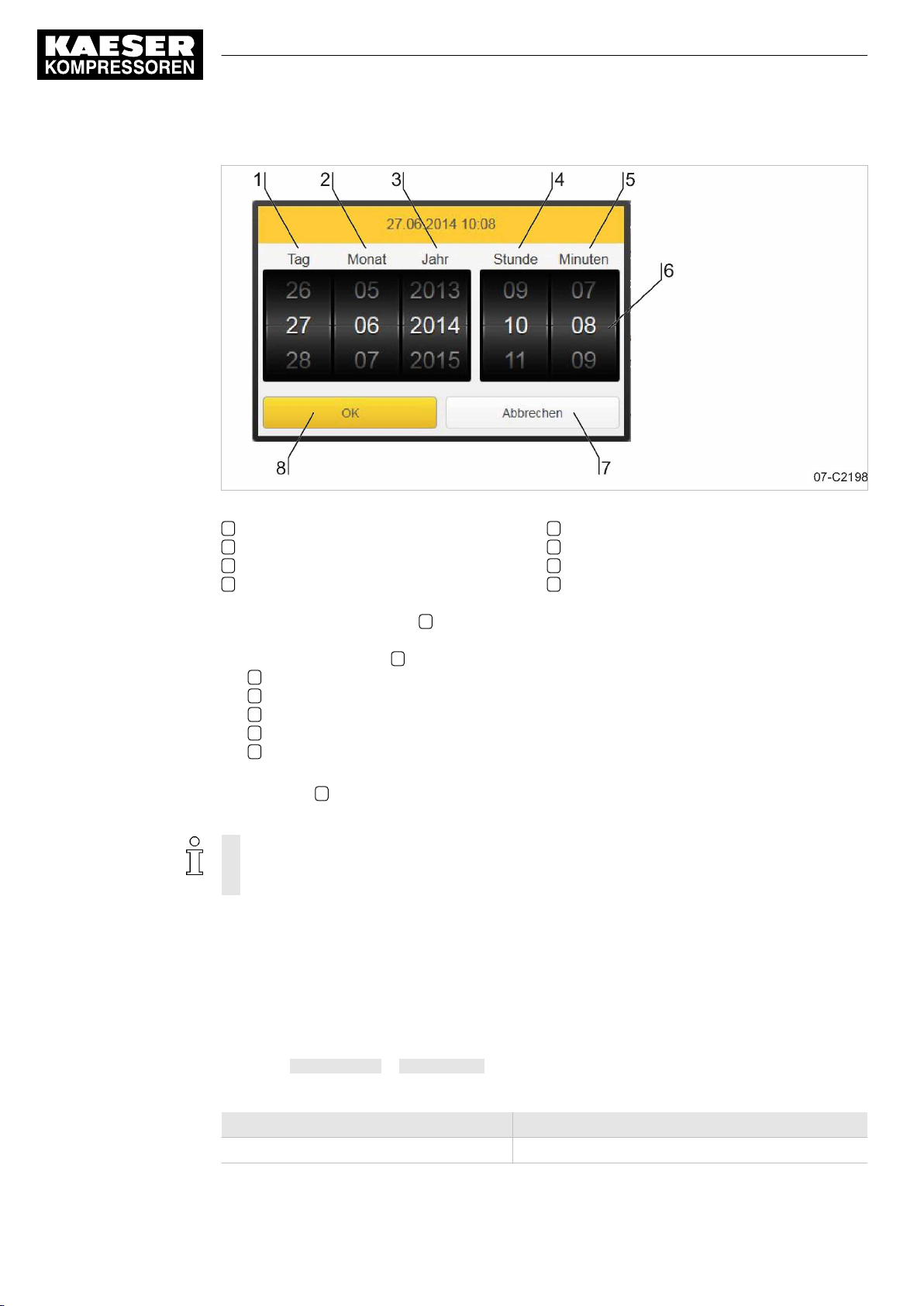
7 Initial Start-up
7.6 Setting the Unit settings
Fig. 31 Setting date and time
1 Day
2 Month
3 Year
4 Hour
3. You can the scroll wheels 6 up or down to change the setting values for date and time. The
display value in the centre is saved as the setting.
Use the scroll wheels 6 to set each value for:
1 Day
2 Month
3 Year
4 Hour
5 Minute
to the current date and current time.
4. Press OK 8 to apply the set date and time.
The display field
Current :
displays the set date and time for verification
■ Regularly (at least once a year) check the time for deviations and adjust, of necessary.
■ The change between daylight savings time and standard time is automatic and follows
the rules for the set time zone.
7.6 Setting the Unit settings
5 Minute
6 Scroll wheel
7 Cancel
8 OK
56
You can adjust the units for some parameters in SAM 2 to the standards in the country of installa‐
tion. The system automatically calculates and displays the correct units.
Precondition Log on with access level 2: Operating (see chapter 7.4 "User log-on").
1. Press Configuration ➙ Unit settings .
The
Unit settings
menu displays the currently set units.
Parameter Unit settings
Pressure bar, psi, M Pa, mbar
Service manual SIGMA AIR MANAGEMENT SYSTEM
SAM 2 No.: 901735 00 E
Page 67
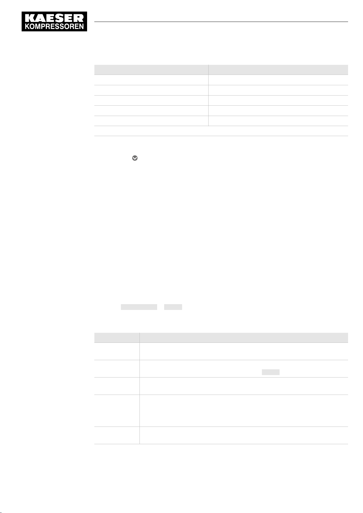
7 Initial Start-up
7.7 Setting up E-Mail
Parameter Unit settings
Free air delivery
Volume
Power kW, W
Specific power
Temperature °C, °F
The factory-set units depend on the "language" set.
Tab. 33 Unit settings
2. Touch the symbol in the line of the parameter to be changed.
The available units are displayed in a list.
3. Select the desired unit.
SAM 2 saves the selected unit and uses it for all display values referenced.
m3/min, CFM
m3, cft
kWmin/m3, kWmin/cft
7.7 Setting up E-Mail
You can set up the sending of messages via e-mail in SAM 2 . The
sub-menus:
■ Send options
■ Basic settings
Precondition Log on with access level 2: Operating (see chapter 7.4 "User log-on").
7.7.1 Send options
Use the
1. Press Configuration ➙ E-Mail .
Parameter Meaning
Send message Touch the option box
Sender's name In this field, enter the name to appear as the sender of e-mails. Touch the input
Contact's phone
number
Repeated send
suppression
time
Send-attempt
interval
Send options
Select the
The
Send options
menu to set the parameters required for sending messages via e-mail.
Send options
of messages. Remove the check mark and e-mail sending is deactivated.
field to display a virtual keyboard. Confirm with Accept to apply the entry.
In this field, enter a telephone number under which the system operator can be
reached. This telephone number is indicated with the e-mail.
The repeat lock time specifies the time interval during which a message cannot
be resent if the same message has already been sent by e-mail. This prevents
multiple sending operations of the same e-mail if a message trigger (e.g., a
loose contact) occurs several times in a short period of time.
In this field, enter the time in seconds to be waited after a failed e-mail sending
operation before the system again attempts to send.
sub-menu.
sub-menu displays the following e-mail parameters:
Active
to set a check mark and activate the e-mail sending
E-Mail
menu has the following
No.: 901735 00 E
Service manual SIGMA AIR MANAGEMENT SYSTEM
SAM 2
57
Page 68
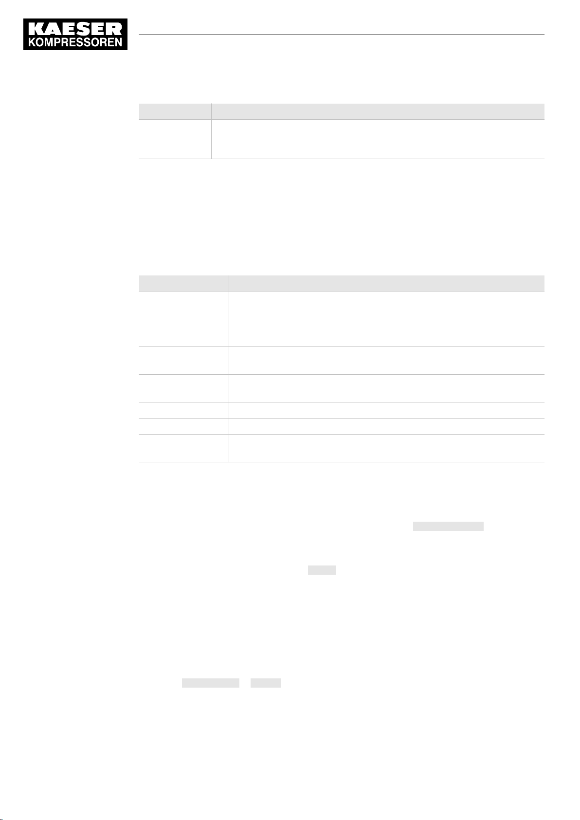
7 Initial Start-up
7.8 Setting up the display
Parameter Meaning
Send-attempt
duration
Tab. 34 E-Mail Send options
Use this setting to specify how long the system is to attempt to e-mail a mes‐
sage. In most cases (but not always), it is advisable to no longer send an old
message when its cause has been probably remedied in the interim.
2. Enter the required data into the
3. The factory-set default values of the remaining data must be adjusted only if needed.
4. Select the
ters required for sending messages via e-mail. Request the required information from your IT
department.
The
Parameter Meaning
Sender's e-mail
address
Receiver's e-mail
address
SMTP Host The IP address of the SMTP mail server receiving and forwarding the mes‐
SMTP Port The port address of the SMTP mail server receiving and forwarding the
SMTP user name The log-in user name for logging on to the SMTP mail server.
SMTP Password The log-in password for logging on to the SMTP mail server.
SMTP Timeout In this field, enter the seconds for SAM 2 to wait for a reply by the SMTP
Tab. 35 E-Mail Basic settings
Basic settings
Basic settings
Sender's name
sub-menu. Use this menu to set the e-mail communication parame‐
sub-menu displays the following e-mail parameters:
The e-mail address used by the sender.
The e-mail address of the recipient. You can only enter one e-mail address.
sage.
message.
server before cancelling sending.
and
Contact's phone number
fields.
5. Enter the required communication parameters into the data fields.
All data fields are completed.
6. You can now send a test message to verify the settings. Press Send test E-mail .
You have completed the settings upon verification of the successful reception of the test mail.
7. Select the
8. In the
box and e-mail sending is activated.
Send options
Send message
sub-menu.
field, touch the Active option box. A check mark appears in the option
7.8 Setting up the display
You can adjust the display brightness and the time behaviour of the screen saver.
Precondition Log on with access level 2: Operating (see chapter 7.4 "User log-on").
1. Press Configuration ➙ Display.
2. Set brightness and time behaviour.
58
Service manual SIGMA AIR MANAGEMENT SYSTEM
SAM 2 No.: 901735 00 E
Page 69
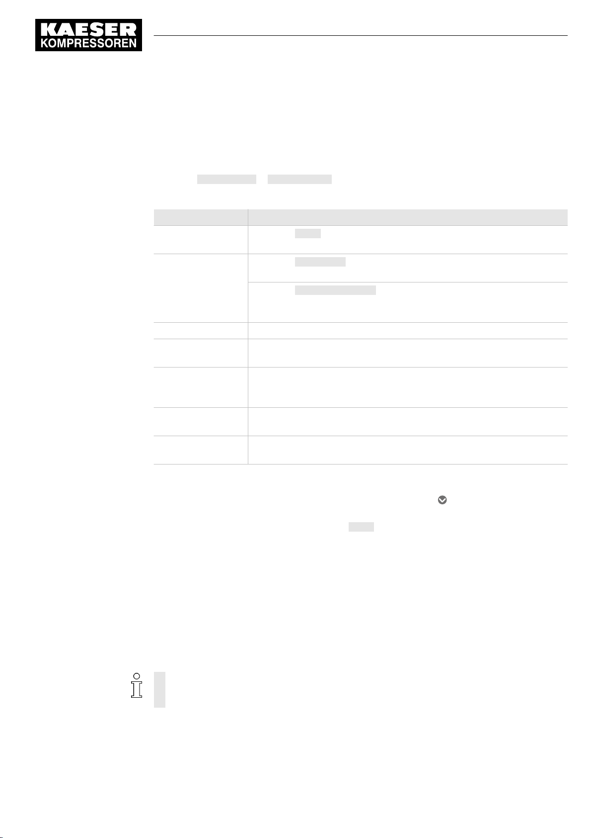
7 Initial Start-up
7.9 Setting the Data recording
7.9 Setting the Data recording
Use the
Precondition Log on with access level 2: Operating (see chapter 7.4 "User log-on").
1. Press Configuration ➙ Data recording .
Parameter Meaning
Data recorder active Touch the Active option box to set a check mark and activate internal data
Data to be recorded Touch the Station map to activate data recording for the compressed air
Resolution This setting specifies the time between the individual measuring points.
Every nth station
map
Current allocation The system displays here information about the current memory allocation
Buffer emptied on This variable displays the time of the last data recording reset for informa‐
Buffer full on This variable displays the time at which the internal data memory was full.
Data recording
The
Data recording
menu to set automatic data recording for the SAM 2 .
menu displays the currently set parameters.
recording.
station.
Touch the System information option box to activate the recording of the
SAM 2 system data. These data can be useful when determining the cause
of a fault.
Use this setting to specify whether every station map is recorded or only
every second, fourth or eighth station map.
in MB and as a percentage value of the data volume internally recorded by
SAM 2 .
tion purposes.
The system no longer records data after this time.
Tab. 36 Data recording
2. If required, change the setting by touching the option box or the symbol and selecting the
available setting values.
3. In the
Data recorder active
tion box and data recording is activated.
7.10 Periphery
The communication between SAM 2 and the connected machines and devices must be configured
to ensure proper functioning.
➤ Enter the settings in the sequence described below:
7.10.1 Starting the SBU
During the registration process, you can only register one SBU at SAM 2 at any time. If you
want to register multiple SBU , you have to do this in sequence. Any SBU not yet registered
must remain deactivated.
Follow the following sequence to ensure the proper commissioning of the SBU .
field, touch the Active option box. A check mark appears in the op‐
No.: 901735 00 E
Service manual SIGMA AIR MANAGEMENT SYSTEM
SAM 2
59
Page 70
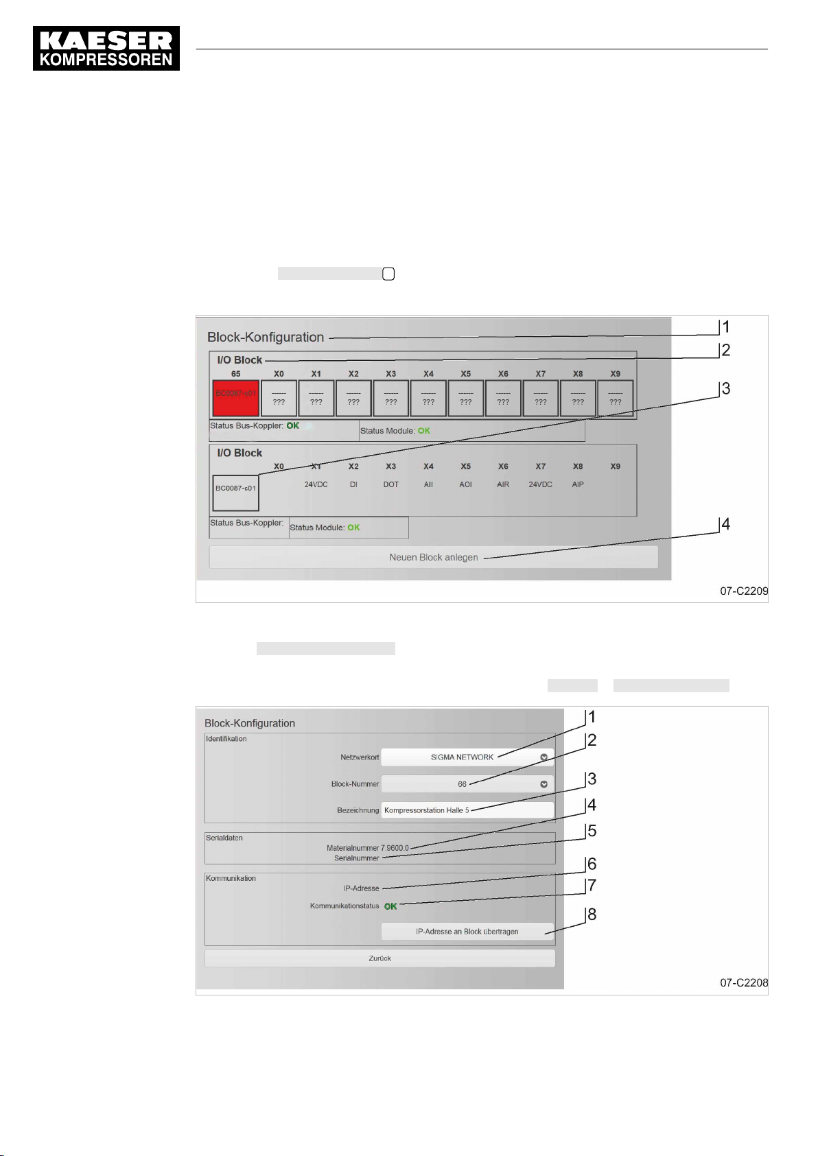
7 Initial Start-up
7.10 Periphery
Precondition All installation tasks and wiring as described in chapter 6 "Installation" are properly completed.
The SAM 2 is switched on.
SBU is switched off at the supply disconnect device
1. Switch on the supply disconnect device for the SBU .
The L/A IF1 LED at the Bus controller of the SBU illuminates green.
At the SAM 2 , a pop-up window displays
2. Press the Create new block 4 key.
A pop-up window displays
New I/O block added
New Bus controller detected
.
Fig. 32 Block configuration menu
3. Press Configure new I/O block.
The
Block configuration
Alternatively, you can manually access this menu: Press Start-up ➙ SIGMA NETWORK .
Fig. 33 I/O block menu
menu opens.
60
Service manual SIGMA AIR MANAGEMENT SYSTEM
SAM 2 No.: 901735 00 E
Page 71
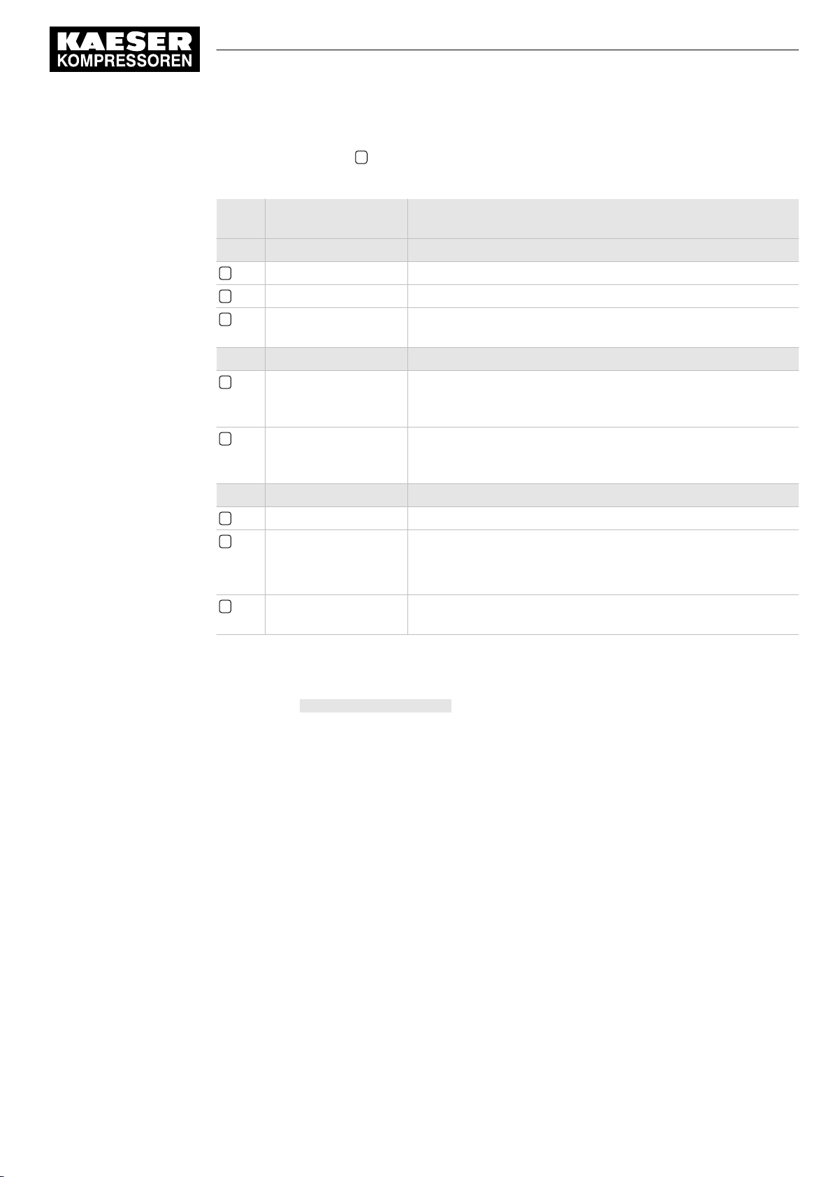
7 Initial Start-up
7.11 P+I diagram
4. Select I/O block 66 2 .
The
Block configuration
sub-men displays these parameters:
Item
Parameter Meaning
No.
Identification
1 Network location Select the name of the network from the list.
2 Block number Select a SIGMA NETWORK address of the SBU from the list.
3 Description In this field, enter an explanatory name (Compressor station Hall
5, for example) for the SBU .
Serial data
4 Material number If possible, the Material number from the SBU is retrieved and
displayed here. Alternatively, you can manually enter the Material
number .
5 Serial number If possible, the Serial number from the SBU is retrieved and dis‐
played here. Alternatively, you can manually enter the Serial
number .
Communication
6 IP address This field displays the IP address currently assigned to SBU .
7 Communication status This field displays the current communication status:
■ Not connected
■ OK
8 Send IP address to
Use this key to transfer changed settings to the Bus controller .
block
Tab. 37 Block configuration menu
5. If necessary, add or adjust the settings in the
< Block configuration >
6. Press the Send IP address to block key.
A message is displayed.
7. Confirm the message.
The network configuration for SBU is completed.
For the configuration of the I/O block see chapter "I/O block configuration".
8. If you want to register other SBU at the SAM 2 , you must follow the procedure described
above from item 1. for every SBU .
7.11 P+I diagram
The fundamental configuration of the compressed air station is realised with a visual P&I diagram
in SAM 2 . Using a graphical editor, you place, configure and connect the components retrieved
from a library in the drawing area.
Precondition Log on with access level 2: Operating (see chapter 7.4 "User log-on").
menu.
No.: 901735 00 E
Service manual SIGMA AIR MANAGEMENT SYSTEM
SAM 2
61
Page 72
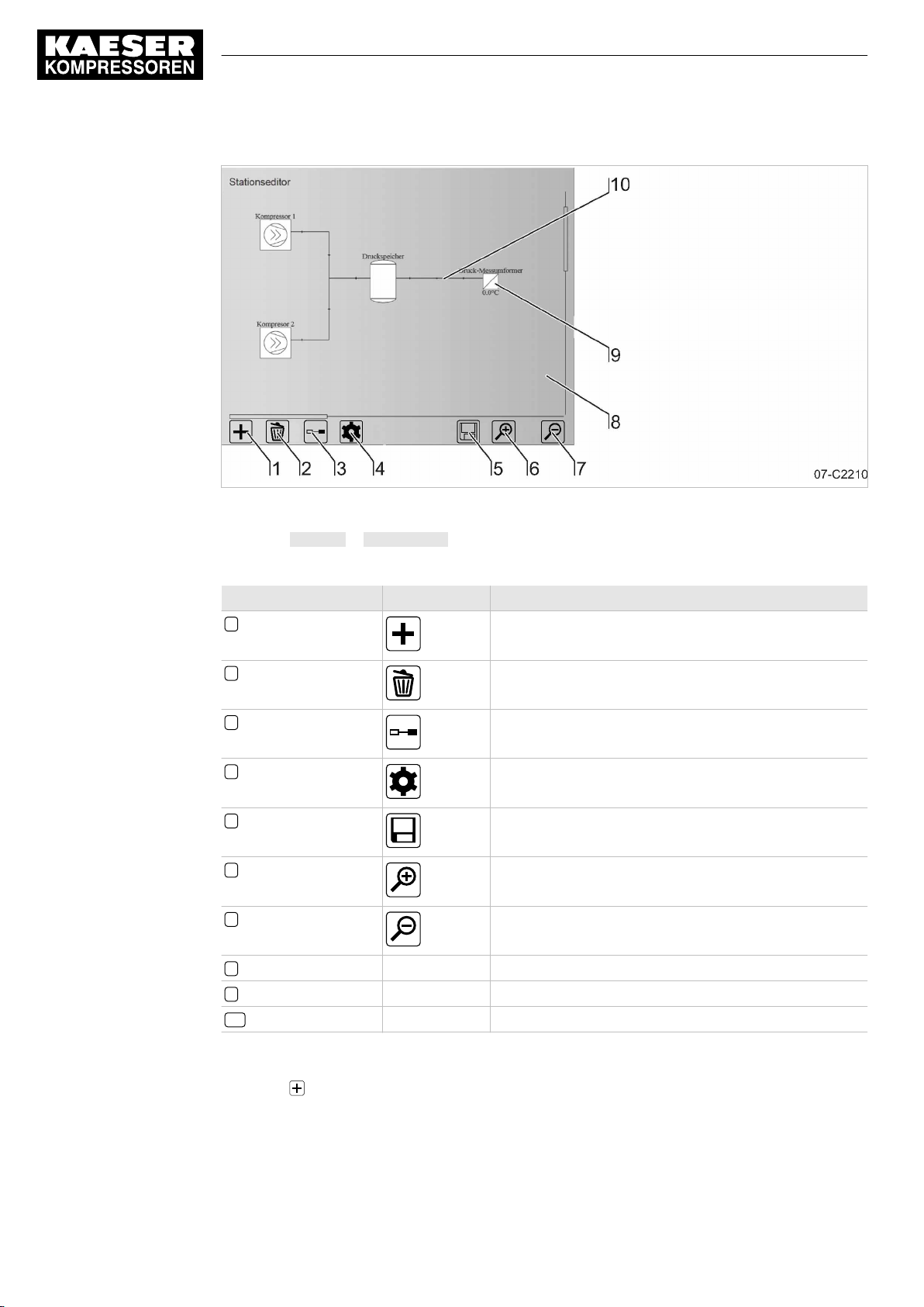
7 Initial Start-up
7.11 P+I diagram
Fig. 34 Station editor menu
1. Press Start-up ➙ P+I diagram .
Station editor
The
Item No. Sign Meaning
1 Add component
2 Remove component
3 Connect components
4 Component details
5 Save
6 Enlarge view
7 Reduce view
menu is displayed.
62
8 – Drawing area
9 – Component
10 – Connection
Tab. 38 Station editor
2. Press .
The
Add component
The Component menu is active.
Service manual SIGMA AIR MANAGEMENT SYSTEM
SAM 2 No.: 901735 00 E
menu is displayed.
Page 73
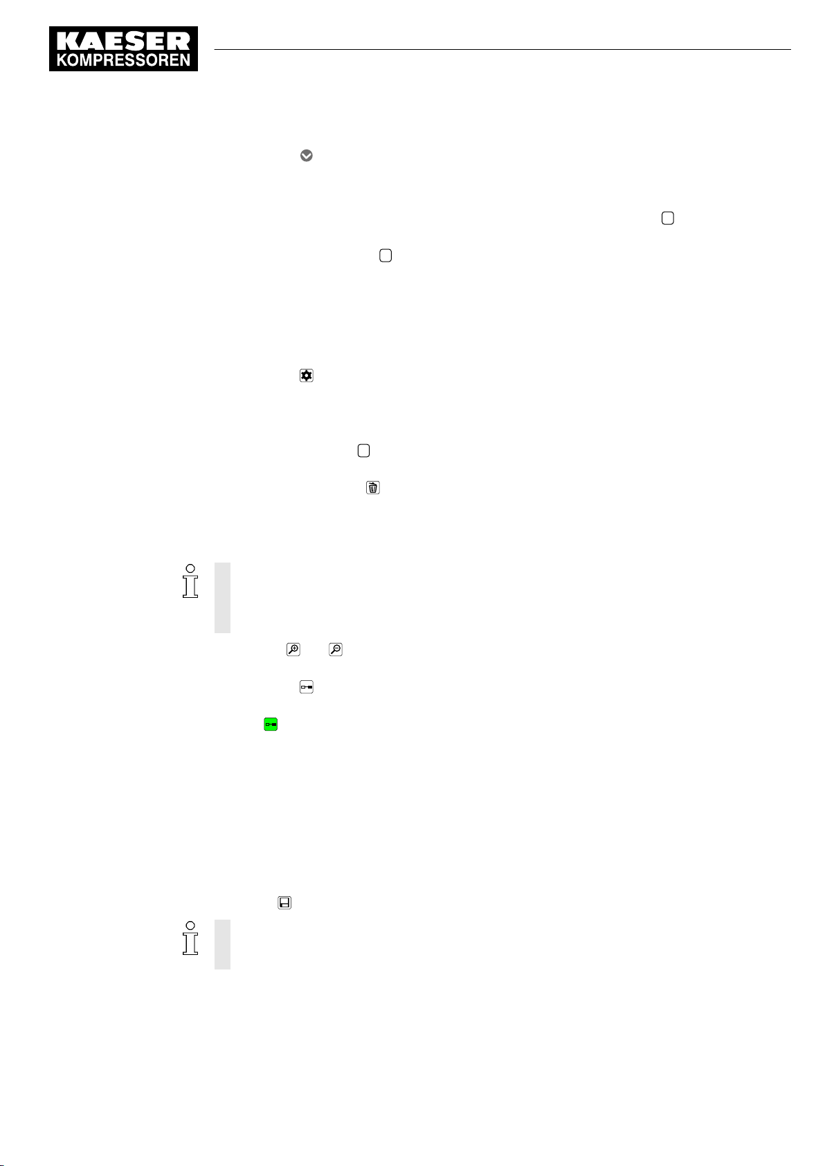
7 Initial Start-up
7.11 P+I diagram
3. Touch the symbol.
The available component types are displayed in a list (see chapter 7.11.1 "Component types)".
4. Add component: Select the required component by touching it.
The selected component is copied to the clipboard and the drawing area 8 of the Station Edi‐
tor opens.
5. Touch the drawing area 8 at the desired location.
The previously selected component is pasted on the touched position on the drawing area.
The placed component is framed by dashed line. This identifies the component as currently
inactive.
6. Touch the placed component.
The selected component is framed in grey.
7. Touch the symbol.
The
Details
"Configuring the components").
8. Moving a component: Touch and drag the component (without releasing it) to another position
on the drawing area 8 .
9. Delete component: Touch to mark the component to be deleted (the selected component will
be framed) and press .
The marked component is removed.
10. Add any other components as described above, until all components required for the P&I dia‐
gram are placed on the drawing area and arranged as required.
menu opens. Configure the details for the selected component (see chapter 7.11.2
The number of possible compressors is limited by the SAM 2 type available (see chapter 2.3
"Technical Specification" ). However, for the SAM 2-4 and SAM 2-8 types, it can be expan‐
ded by Upgrade (see chapter "Upgrade" ).
The P&I diagram flows from left to right.
11. Use the and symbols to enlarge or reduce the view of the drawing area.
Touch and drag the drag arrows to move the view into the desire direction.
12. Touch the symbol.
The connecting mode is active.
The symbol is displayed with a green background.
13. Add connection: Touch the first component to be connected.
The selected component is framed in grey.
14. Touch the second component to be connected.
A connecting line is drawn between both components.
The dashed frame of the first component disappears. This marks this component to be active.
15. Delete connection: Execute the same procedure as described in "Add connection".
16. Add all other connections as described above, until all components of the P&I diagram are
connected.
17. Touch to save the completed P&I diagram.
The above created P&I diagram of the compressed air station will be used as the valid config‐
uration of SAM 2 for machine control, calculations and display purposes only after it has been
saved.
No.: 901735 00 E
Service manual SIGMA AIR MANAGEMENT SYSTEM
SAM 2
63
Page 74
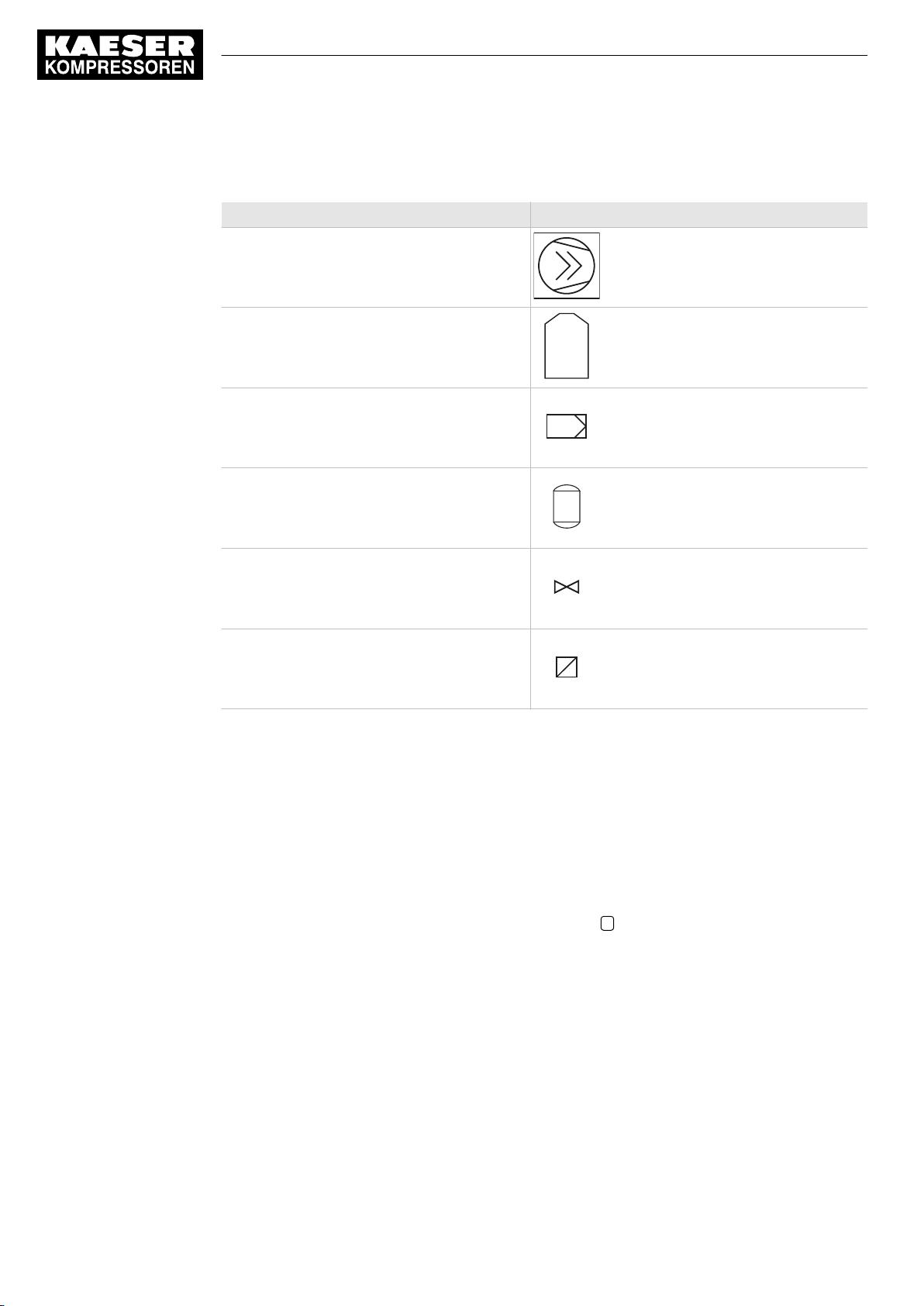
7 Initial Start-up
7.11 P+I diagram
7.11.1 Component types
Component type Symbol (example)
Compressor
Dryer
Filter
Receiver
Valve
Sensor
Tab. 39 Component types
7.11.2 Configuring the components
You must properly configure the components shown in the P&I diagram in order for SAM 2 to re‐
ceive the correct parameters for output calculations, network communication and maintenance, for
example.
Precondition Log on with access level 2: Operating (see chapter 7.4 "User log-on").
The Component mode is active (see chapter 7.11 "P+I diagram" ).
At least one component is positioned on the drawing area 8 (see chapter 7.11 "P+I diagram" ).
1. Configuring the component: select the required component by touching it.
The selected component is framed in grey.
64
Service manual SIGMA AIR MANAGEMENT SYSTEM
SAM 2 No.: 901735 00 E
Page 75
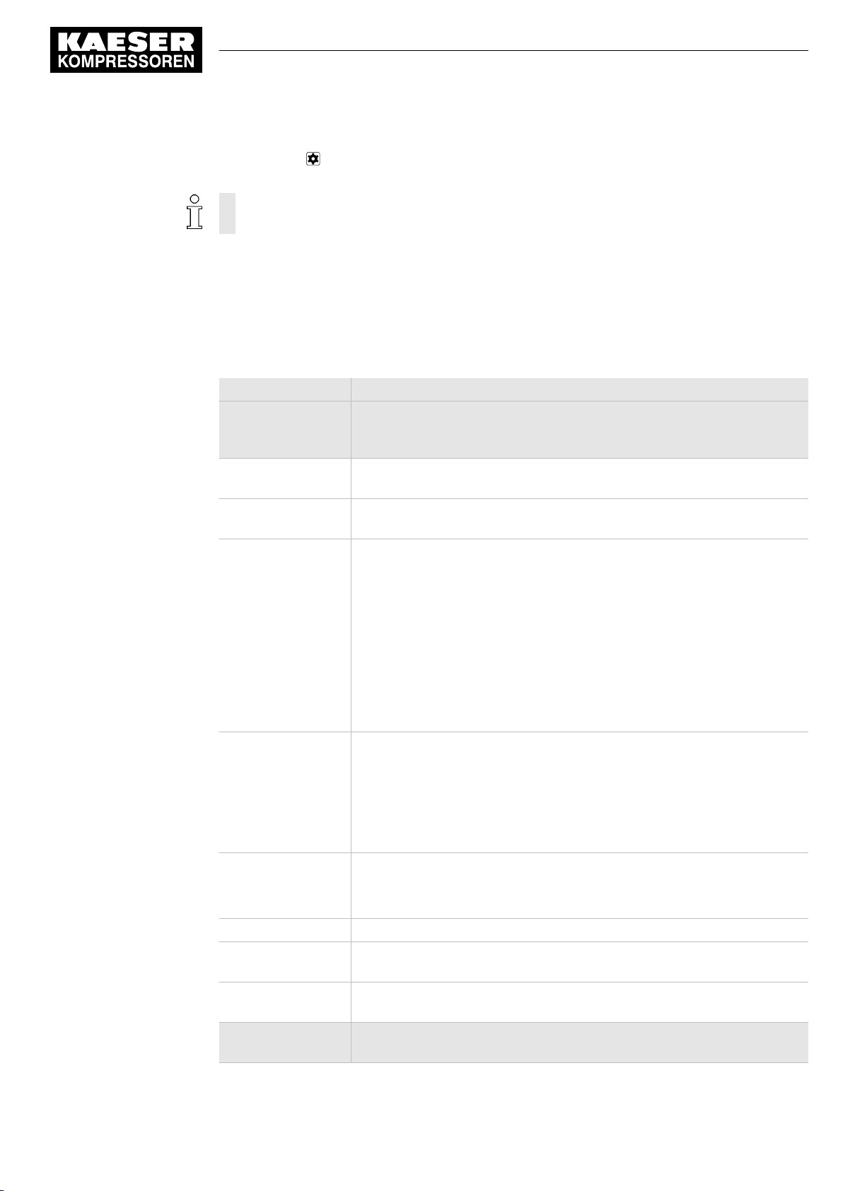
7 Initial Start-up
7.11 P+I diagram
2. Touch the symbol.
The configuration menu for the selected component is displayed.
The items available in the configurations depend on the selected component type.
The configuration menu has maximally the following sub-menus:
■ Connection
■ Identification
■ Performance data
■ Maintenance management
3. Select a sub-menu.
Parameter Meaning
Connection Use this menu to set the fundamental communication options for connect‐
ing the selected component with SAM 2 . Some options are available only
for certain components.
Number The system automatically assign a unique ID to every component. This en‐
ables the activation of the component via "SAM 2.Logic" for example.
Active Touch the option box
nals of the corresponding component will be evaluated by SAM 2 .
Connection type Set here the connection type:
■ Controlled: The component is automatically controlled.
■ Monitored+: The component is not automatically controlled and oper‐
ates independently.
■ Monitored: The component is not automatically controlled and operates
independently. The component is not taken into account when the com‐
pressed air station is energetically evaluated.
■ Not connected: The component is only displayed in the P&I diagram.
Active
to set a check mark which ensures that the sig‐
Only machines are controlled.
Communication me‐
dium
Controller type The type of KAESER controller is displayed here:
IP address The IP address of the component is displayed.
PROFIBUS slave
address
Definition of conven‐
tional signals
Identification In this menu, enter general information about the component to be regis‐
Set here the communication medium:
■ SIGMA NETWORK
■ PROFIBUS
■ conventional
Only machines are controlled via SIGMA NETWORK or PROFIBUS.
■ SIGMA CONTROL
■ SIGMA CONTROL 2
Enter here the PROFIBUS slave address.
Use this key to open the
tered.
<Conventional signals>
menu.
No.: 901735 00 E
Service manual SIGMA AIR MANAGEMENT SYSTEM
SAM 2
65
Page 76
7 Initial Start-up
7.12 Control
Parameter Meaning
Description The name of the component within the compressed air station, for example
"Compressor 1".
Material number The manufacturer's article number for the component.
Serial number The manufacturer's serial number for the component.
Equipment number The KAESER-specific number.
Device type The manufacturer's type designation for the component.
Manufacturer The name of the component manufacturer.
Performance data Use this menu to enter the basic technical data for the component previous‐
ly registered in the
Obtain this information from the nameplate and/or the operating manual.
Rated pressure Enter the component's rated pressure in the set unit of pressure.
Rated power Enter the component's rated power in the set unit of power.
Rated air delivery Enter the component's rated air delivery in the set unit of delivery volume.
Idle power Enter the power consumption in IDLE in the set unit of power.
Variable speed Touch the option box
speed" option.
Add-on dryer Touch the option box
dryer" option.
Speed parameter
field
Add-on dryer techni‐
cal data
Copying technical
data from the SD
card
Maintenance
management
Maintenance
management via
SAM 2
Use this key to open the
Use this key to open the
Use this key to open the
Set the maintenance options in this menu.
Touch the option box
Maintenance management option. SAM 2 now manages the component's
maintenance signals in the
Identification
Active
Active
menu.
to set a check mark and activate the "Variable
to set a check mark and activate the "Add-on
Speed parameter field
Add-on dryer
SC card
Active
menu.
to set a check mark and activate the
< Messages >
menu.
menu.
menu.
66
Tab. 40 Parameters in the configuration menu
4. Set all required parameters for the selected component in the provided sub-menus as descri‐
bed above.
7.12 Control
The Control parameter menu has the following sub-menus:
■ "Parameter"
■ Priority
■ Dynamic Control
■ "Required pressure"
1. Press Control ➙ Settings or Control ➙ Pressure parameters .
Service manual SIGMA AIR MANAGEMENT SYSTEM
SAM 2 No.: 901735 00 E
Page 77

7 Initial Start-up
7.12 Control
2. If the menu page displayed has several sub-menus, touch one of the tabs to open the corre‐
sponding sub-menu.
3. Enter the required parameters in the corresponding fields.
4. If necessary, activate the desired functions by touching the selection box.
7.12.1 Setting the Parameter
The fundamental pressure values of the station must be set in the Parameter menu.
7.12.1.1 Pressure range upper limit [pR]
You define the pressure margin by setting a pressure value above the required pressure.
For example, if you want a required pressure of 7.0 bar and a pressure margin of 0.5 bar,you must
specify 7.5 bar as value for the upper pressure margin.
7.12.1.2 Pressure range
The pressure margin is the difference resulting from the upper margin limit and the required pres‐
sure.
For energetic reasons, select the largest possible pressure margin. Practical values are 0.8–1.2
bar, for example. Lower values for the pressure margin result in more frequent machine motor
starts.
7.12.1.3 Required pressure [pREQ]
The required pressure is the pressure required by the consumers in the compressed air network
(measured with the "pressure transducer").
SAM 2 usually maintains the required pressure with a maximum deviation of 0.1 bar. For energetic
reasons, the operating pressure is to be set as low as possible, i.e., not higher as required for the
consumers within the compressed air network. A pressure of 1 bar higher than required causes ap‐
proximately 6 % more energy consumption.
7.12.1.4 Maximum pressure
Pressure high [ph] is a monitoring function. If the monitoring function is activated, the system is‐
sues a warning message as soon as the mains pressure exceeds the set threshold value for the
set time.
7.12.1.5 Minimum pressure
Pressure low [pt] is a monitoring function. If the monitoring function is activated, the system issues
a warning message as soon as the mains pressure falls below the set threshold value for the set
time.
No.: 901735 00 E
The monitoring function is provided in two variants:
■ Δpt: This monitoring function uses a pressure limit relative to the set required pressure.
■ pt: This monitoring function uses a pressure limit which is independent of the required pres‐
sure.
You cannot use both variants at the same time.
Service manual SIGMA AIR MANAGEMENT SYSTEM
SAM 2
67
Page 78
7 Initial Start-up
7.13 Activating SAM 2
7.12.2 Setting the Pressure parameters
Use this menu to specify the limits within the working pressure may be set ( SAM 2 ) or specified (
Process control ).
7.12.2.1 Maximum required pressure
The maximum working pressure represents the upper pressure limit which still ensures safe opera‐
tion for the consumers within the air network.
7.12.2.2 Required pressure minimum
The minimum working pressure represents the lower pressure limit which still ensures safe opera‐
tion for the consumers within the air network.
7.12.2.3 Decrease of required pressure
You can lower the required pressure by an adjustable amount either manually or by an external
signal.
7.13 Activating SAM 2
Precondition Nobody is working on the machine.
All access doors on the machines are closed.
The ambient conditions for SAM 2 are met as described in chapter 5. "Installation and Operating
Conditions"
The temperature of the machines is not below +3 °C.
All installation tasks and wiring as described in chapter 6 "Installation" are properly completed.
There is no bus error.
WARNING
Risk of injury during an automatic machine start.
➤ Before switching on, make sure that all conditions are met.
➤ Compare the settings for initial start-up of SAM 2 with those listed in the operating man‐
ual.
➤ Use the "Commissioning" check list.
To be checked Description Confirmed?
date and time is set Chapter 7.5 "Date and time"
machines are set up Chapter 6.12 "Setting up the machines"
Machines are connected Chapter 7.10 "Periphery"
Required pressure is set Chapter 7.12 "Control"
68
Tab. 41 "Commissioning" check list
Precondition All points in the "Commissioning" check list are complied with,.
➤ Key "Automatic" Press .
Result Key "Automatic" illuminates green.
Service manual SIGMA AIR MANAGEMENT SYSTEM
SAM 2 No.: 901735 00 E
Page 79

7 Initial Start-up
7.13 Activating SAM 2
SAM 2 assumes control of the compressed air station.
No.: 901735 00 E
Service manual SIGMA AIR MANAGEMENT SYSTEM
SAM 2
69
Page 80
8 Operation
8.1 Switching on and off
8 Operation
8.1 Switching on and off
Precondition The ambient conditions are met as described in chapter 5. "Installation and Operating Conditions"
All installation tasks and wiring as described in chapter 6 "Installation" are properly completed.
Commissioning in accordance with chapter 7 "Initial Start-up" is completed.
8.1.1 Switching the compressed air station on
➤ Press the key.
Result The compressed air station switches on.
The key illuminates green.
8.1.2 Switching the compressed air station off
You can switch off the compressed air delivery for the entire station at SAM 2 .
➤ Press the key.
Result The compressed air station shuts down and compressed air is no longer delivered.
The key illuminates red.
8.2 Help function
SAM 2 features an integrated Help function. A matching description can be displayed for the cur‐
rently displayed menu.
1. Press the key.
The matching Help page is displayed.
2. If the Help page is more than one screen page, swipe with your finger up or down.
3. Touching underlined terms opens further Help pages with corresponding descriptions.
4. Use the and keys to browse back and forward in the Help file.
5. Press to open the table of contents.
6. Press to open the glossary.
7. Press to return to the Help page of the current SAM 2 menu.
8. Press again.
The Help page is closed and the current SAM 2 menu is again displayed.
When you close the currently displayed Help page and again call up the Help function, the
page displayed is the same page which you saw before closing the function.
If you close the currently displayed Help page 10 minutes after the initial call up, the system
displays the initially description matching the menu when you re-call the Help function.
70
8.3 Main menu
The menu has the following sub-menus:
■ Net pressure station
■ Net pressure
Service manual SIGMA AIR MANAGEMENT SYSTEM
SAM 2 No.: 901735 00 E
Page 81

8 Operation
8.3 Main menu
■ Current values
■ Total values
■ Drag Indicator
■ View station
1. Press Status ➙ Overview or Status ➙ View station .
2. If the menu page displayed has several sub-menus, touch one of the tabs to open the corre‐
sponding sub-menu.
8.3.1 Net pressure station
The pressure curve is the visual display of the network pressure progression and set limit values
for the entire station or the selected machines.
One or more pressure transducers in the network provide the measured values. " " If multiple pres‐
sure transducers are used, the software calculates a weighted mean value.
The values are displayed in the previously set units for the set time axis.
8.3.1.1 Net pressure [pN]
The system displays the progression curve of the network pressure over the time axis.
The values are displayed in the set unit.
8.3.1.2 Required pressure [pREQ]
The required pressure is the pressure required by the consumers in the compressed air network
(measured with the "pressure transducer").
SAM 2 usually maintains the required pressure with a maximum deviation of 0.1 bar. For energetic
reasons, the operating pressure is to be set as low as possible, i.e., not higher as required for the
consumers within the compressed air network. A pressure of 1 bar higher than required causes ap‐
proximately 6 % more energy consumption.
8.3.1.3 Pressure range
The pressure margin is the difference resulting from the upper margin limit and the required pres‐
sure.
For energetic reasons, select the largest possible pressure margin. Practical values are 0.8–1.2
bar, for example. Lower values for the pressure margin result in more frequent machine motor
starts.
8.3.1.4 Compressor
No.: 901735 00 E
The machine's name within the station. This name can be set in the P&I diagram menu.
8.3.1.5 Free air delivery
Current compressed air volume delivered by the machine.
The values are displayed in the set unit.
8.3.1.6 Pi
Current compressed air volume generated by the machine.
Service manual SIGMA AIR MANAGEMENT SYSTEM
SAM 2
71
Page 82

8 Operation
8.3 Main menu
The values are displayed in the set unit.
8.3.1.7 ADT
"Airend discharge temperature" of the machine.
The values are displayed in the set unit.
8.3.1.8 Operating state
Current operating state of machine, for example:
■ READY
■ IDLE
■ LOAD
8.3.1.9 Error state
Current fault state of machine, for example:
■ Fault
■ Warning
■ Communication alarm
■ Local mode
8.3.2 Pressure chart
This sub-menu page displays the current network pressure as numerical value in large font.
This display type enables good legibility from a larger distance.
The values are displayed in the set unit.
8.3.3 Current values
The display of current measuring values of the entire station or selected machine(s).
8.3.3.1 Power
The display of the currently measured power consumption of the entire station or selected ma‐
chine(s).
The values are displayed in the set unit.
8.3.3.2 Free air delivery
The compressed air volume currently delivered by the entire station or selected machine(s).
The values are displayed in the set unit.
8.3.3.3 Specific power
This standard value is used as reference value in the assessment of the station's efficiency, The
value is calculated from the power consumption per delivery volume. Lower values indicate a high
degree of efficiency.
72
Service manual SIGMA AIR MANAGEMENT SYSTEM
SAM 2 No.: 901735 00 E
Page 83
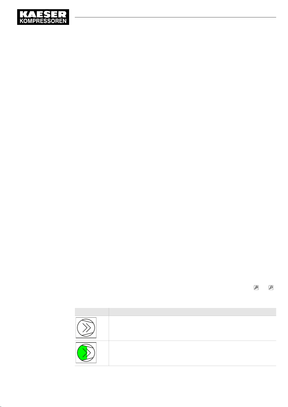
8 Operation
8.3 Main menu
8.3.3.4 Switch events
The number of motor starts of the selected machine within the last 60 minutes.
8.3.3.5 Consumption
Calculated current compressed air usage in the air network.
The values are displayed in the set unit.
8.3.4 Drag Indicator
This sub-menu page records the maximum, mean or minimum pressure values.
8.3.4.1 Maximum pressure
The maximum pressure in the network, measured from the reference time set. This value corre‐
sponds to the highest measured pressure in the network and can be used to evaluate the com‐
pressed air quality.
The values are displayed in the set unit.
8.3.4.2 Average pressure
The mean pressure in the network, calculated since the reference time set.
The values are displayed in the set unit.
8.3.4.3 Minimum pressure
The minimum pressure in the network, measured from the reference time set. This value corre‐
sponds to the lowest measured pressure in the network and can be used to evaluate the com‐
pressed air quality.
The values are displayed in the set unit.
8.3.4.4 RESET
The set reference time is reset to the current date and the current time.
8.3.5 Station view
Display of the P&I diagram of the compressed air station. The P&I diagram illustrates the structure,
operating modes and important data of the station and is updated continuously. Use the and
symbols to scale the view and move it by touching and dragging with your finger.
The display of the symbols changes with the operating state of the corresponding machine.
Sign Meaning
Machine in operating mode READY
No.: 901735 00 E
Machine in operating mode IDLE
Service manual SIGMA AIR MANAGEMENT SYSTEM
SAM 2
73
Page 84
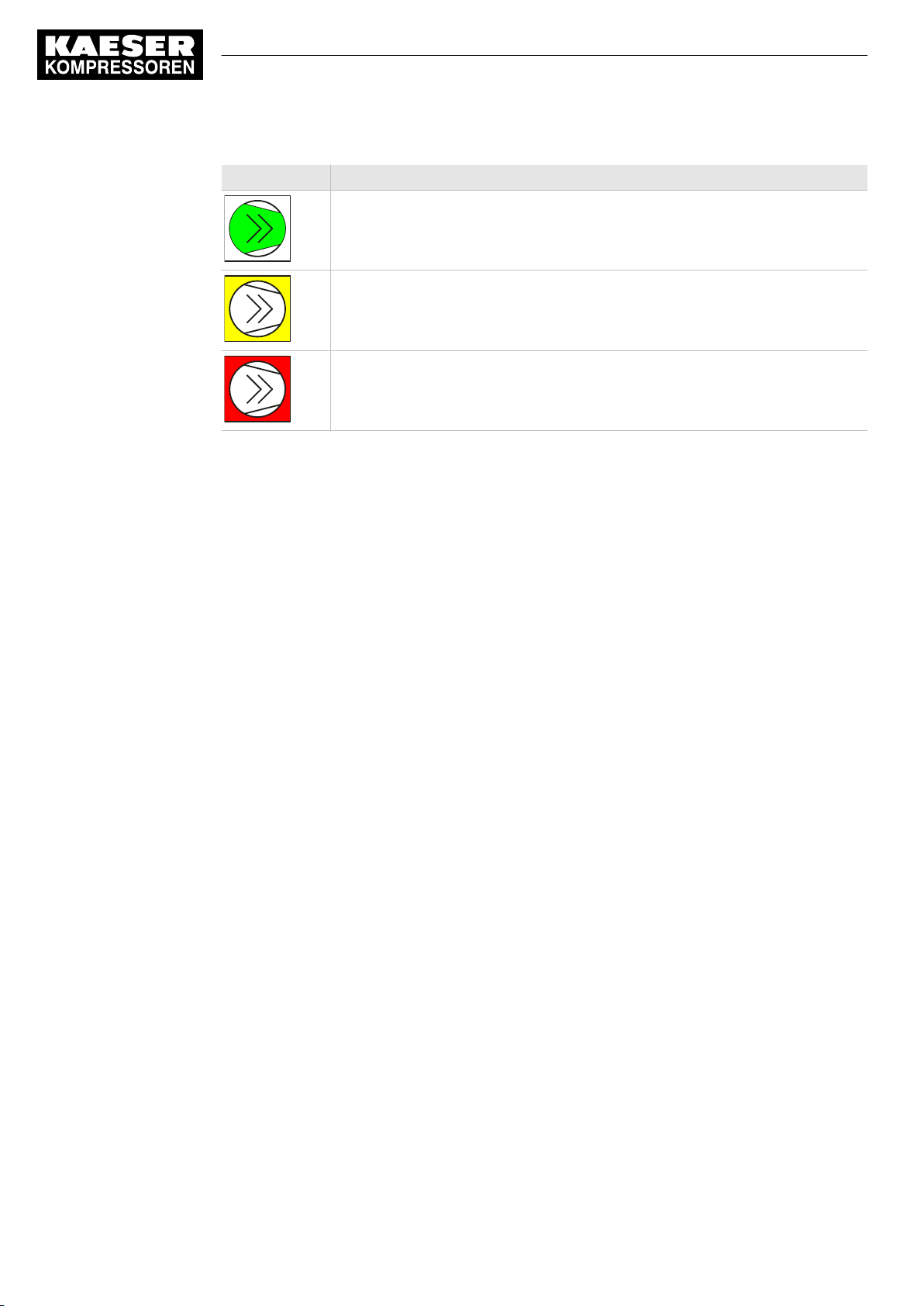
8 Operation
8.3 Main menu
Sign Meaning
Machine in operating mode LOAD
Machine has warning messages or service messages
Machine has fault messages
Tab. 42 Symbols in View station
74
Service manual SIGMA AIR MANAGEMENT SYSTEM
SAM 2 No.: 901735 00 E
Page 85
9 Fault Recognition and Rectification
9.1 KAESER SERVICE
9 Fault Recognition and Rectification
9.1 KAESER SERVICE
The messages valid for SAM 2 are dependent on how the compressor station is equipped.
1. Do not attempt fault rectification measures other than those given in this manual!
2. If the fault cannot be removed by the action suggested: Contact KAESER SERVICE.
9.2 Messages
Alarm, service and warning messages are displayed at SAM 2 and stored in the event memory. A
pop-up window appearing on top of the current display notifies the user of new messages.
New messages are displayed together with the following data:
■ Event :
─ Number of messages: Error
─ Number of messages: Warning
─ Number of messages: Maintenance
You must acknowledge the messages.
➤ Press Active reports to open the
The event memory differentiates between:
■ Unacknowledged messages
■ Current reports
■ Message history storing the last 1000 messages.
1. Press Message .
2. Select a menu option:
■ Unacknowledged messages
■ Current reports
■ Message history
The system displays three different event times for individual messages:
─ Event “k”: Message coming
─ Event “q”: Message acknowledged
─ Event “g”: Message gone
■ The following data are shown in addition:
─ Time : Date and time
─ Number : Message number
─ component
─ Message : Message text
3. If the message list is longer than one screen page, swipe with your finger up or down.
4. In the Unacknowledged messages message page, touch an individual message for selection.
Press Acknowledge message to acknowledge the message.
< Unacknowledged messages >
menu.
No.: 901735 00 E
Service manual SIGMA AIR MANAGEMENT SYSTEM
SAM 2
75
Page 86
9 Fault Recognition and Rectification
9.3 Other faults
9.3 Other faults
Fault Possible cause Remedy
Operation of the touch
screen is difficult and/or re‐
turns errors.
Tab. 43 Other faults
The touch screen is dirty. Wipe the touch screen surfaces
with a soft cloth (micro-fibre, for
example) without any harsh
cleaning agent.
SAM 2 is incorrectly connected
to the equipotential bonding. The
capacitive touch screen must be
earthed to work reliably.
Connect SAM 2 to the equipoten‐
tial bonding (see chapter 6.11.2).
76
Service manual SIGMA AIR MANAGEMENT SYSTEM
SAM 2 No.: 901735 00 E
Page 87
10 Maintenance
10.1 Maintenance tasks on electrical equipment
10 Maintenance
10.1 Maintenance tasks on electrical equipment
Maintenance tasks on electrical equipment may only be carried out by the following persons:
■ Specialist personnel, see chapter 3 “Assigning personnel”.
■ Technicians qualified to maintain SAM 2 and service personnel instructed by and under
the supervision of such a qualified technician
■ Authorised KAESER service personnel.
1. Check personnel for specialised qualifications.
2. Assign suitable personnel to maintenance tasks.
3. Instruct on correct maintenance procedures in accordance with the operating manual.
4. Document maintenance tasks carried out.
Enter completed maintenance tasks in the corresponding lists in the operating manual.
10.2 Additional buffer battery
SAM 2 features a permanently installed buffer battery. In the event of a failure, you can install a
second buffer battery. This additional buffer battery is switched in parallel to the factory-installed
battery and assumes its function. The functionality of this second battery is not impaired by the dis‐
charged factory-installed battery.
➤ Comply with the following instructions.
10.2.1 Danger from batteries
WARNING
There is danger of acid burns if batteries are overheated or damaged.
➤ Store the battery in a cool and dry place.
➤ Properly dispose of discharged buffer batteries.
10.2.2 Buffer battery life
Under normal operating conditions, the buffer battery in SAM 2 has a life of at least 10 years.
NOTICE
Data loss from discharged buffer battery
➤ Heed warning messages from SAM 2 concerning the buffer battery charge level.
➤ Install the additional buffer battery only when SAM 2 is switched on.
No.: 901735 00 E
In the event of a voltage loss and discharged buffer battery, the internal clock is reset to the
date 01.01.1970 after power has returned.
➤ Notice the maximum storage times for unused buffer batteries.
Service manual SIGMA AIR MANAGEMENT SYSTEM
SAM 2
77
Page 88
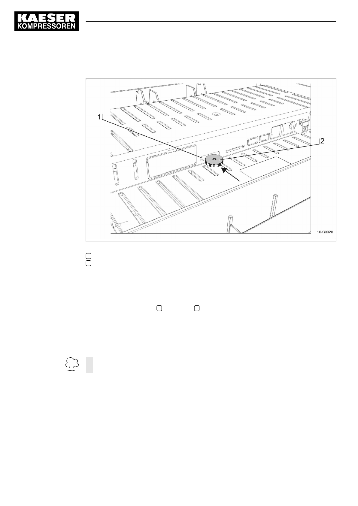
10 Maintenance
10.2 Additional buffer battery
10.2.3 Installing the additional buffer battery
Fig. 35 Buffer battery location
1 Slot for additional buffer battery
2 Buffer battery
Precondition You have a new buffer battery at hand (for article number and type, please see chapter 11).
The SAM 2 is switched on.
1. Use a slot-head screwdriver to break off the plastic cover ("Battery X2") at the rear of SAM 2 .
2. Insert the buffer battery 2 into the slot 1 . The positive pole of the buffer battery points to the
terminal rear.
3. Insert the buffer battery until you feel resistance.
4. Check and correct, if required, the time zone, date and time (see chapter 7.5).
5. Record the installation date of the buffer battery in the maintenance table in the annex of this
operating manual (chapter 13.7).
Discharged batteries are hazardous waste.
➤ Dispose of discharged batteries according to national regulations and directives.
78
Service manual SIGMA AIR MANAGEMENT SYSTEM
SAM 2 No.: 901735 00 E
Page 89
11 Spares, Operating Materials, Service
11.1 Note the nameplate
11 Spares, Operating Materials, Service
11.1 Note the nameplate
The nameplate contains all information to identify your machine. This information is essential to us
in order to provide you with optimal service.
➤ Please give the information from the nameplate with every enquiry and order for spares.
11.2 Spare parts
Name Voltage
Lithium buffer battery 3.0 0.19 CR2032/BR2032
Tab. 44 Spare buffer battery
11.3 KAESER AIR SERVICE
KAESER AIR SERVICE offers:
■ Authorised service technicians with KAESER factory training
■ Increased operational reliability ensured by preventive maintenance
■ Energy savings achieved by avoidance of pressure losses
■ optimum conditions for operation of the compressed air system,
■ The security of genuine KAESER spares.
■ Increased legal certainty as all regulations are kept to.
➤ It make sense to sign a KAESER AIR SERVICE maintenance agreement.
Your advantage:
lower costs and higher compressed air availability.
[V]
Capacity
[Ah]
Model
No.: 901735 00 E
11.4 Displaying the software version
You can display the versions of the various software modules in SAM 2 .
➤ Press Configuration ➙ Software versions .
The
Software versions
Parameter Meaning
Software Software name SAM 2
Tab. 45 Software versions menu
Service manual SIGMA AIR MANAGEMENT SYSTEM
SAM 2
menu is displayed.
79
Page 90
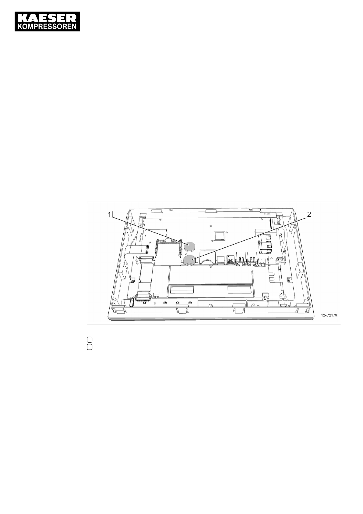
12 Decommissioning, Storage and Transport
12.1 De-commissioning
12 Decommissioning, Storage and Transport
12.1 De-commissioning
De-commissioning is necessary, for example, under the following circumstances:
■ SAM 2 is (temporarily) not needed.
■ SAM 2 is to be moved to another location.
1. Isolate SAM 2 from all power phases (power supply isolating device).
2. Switch off external power sources.
3. Disconnect SAM 2 from all connections when the device is to be moved to another location.
12.2 Disposal
Precondition SAM 2 is de-commissioned.
80
Fig. 36 Buffer battery positions
1 Permanently installed buffer battery
2 Additional buffer battery
1. Disconnect SAM 2 from all connections.
2. Open the control cabinet of the SAM 2 cover (see chapter 6.6).
3. Detach all connections from the SAM 2 terminal.
4. If necessary, use a suitable tool to force the removal of incommoding cover parts.
5. Use a Torx screwdriver to remove the T9 screws at the rear housing panel of the SAM 2 termi‐
nal.
6. Remove the housing panel.
7. Use a suitable tool to remove the permanently installed and any additional buffer battery.
8. Properly dispose of the buffer batteries.
9. Hand the SAM 2 over to an authorised disposal expert.
Service manual SIGMA AIR MANAGEMENT SYSTEM
SAM 2 No.: 901735 00 E
Page 91

12 Decommissioning, Storage and Transport
12.2 Disposal
Discharged batteries are hazardous waste.
➤ Dispose of discharged batteries according to national regulations and directives.
No.: 901735 00 E
Service manual SIGMA AIR MANAGEMENT SYSTEM
SAM 2
81
Page 92
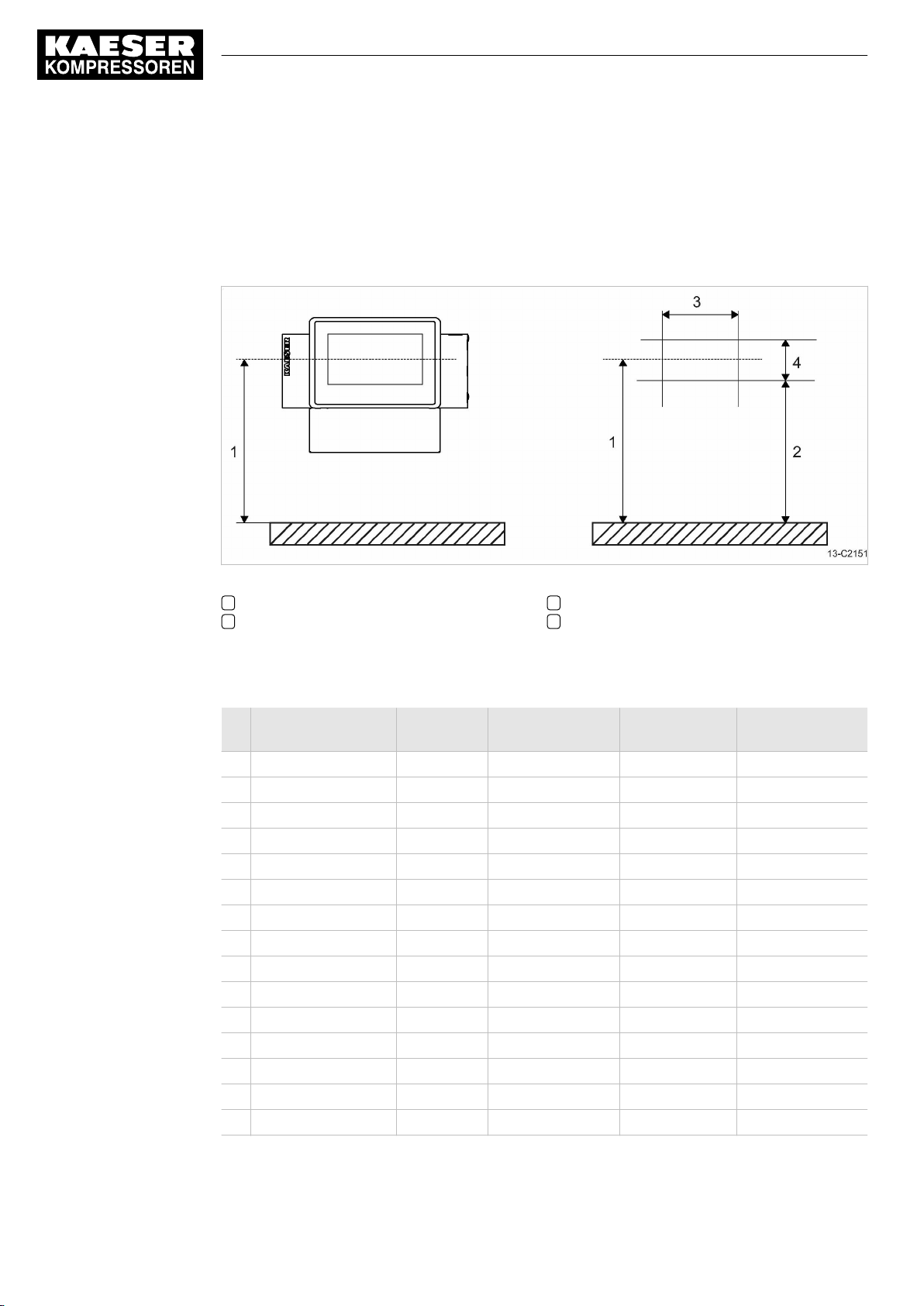
13 Annex
13.1 Anchor holes for the control cabinet
13 Annex
13.1 Anchor holes for the control cabinet
See instructions in chapter 6.6
Fig. 37 Anchor holes for the SAM 2 control cabinet
1 1300 mm
2 1084 mm
13.2 Machine assignment
No. Model Machine
number
1
2
3
4
5
6
7
8
9
10
11
12
13
14
15
3 507 mm
4 180 mm
Year of
manufacture
No. in wiring
diagram
Bus address or
number Slave
82
Service manual SIGMA AIR MANAGEMENT SYSTEM
SAM 2 No.: 901735 00 E
Page 93
13 Annex
13.3 SBU (SIGMA NETWORK BUS CONVERTER)
No. Model Machine
number
16
Tab. 46 Machine assignment
Year of
manufacture
No. in wiring
diagram
13.3 SBU (SIGMA NETWORK BUS CONVERTER)
No. Model Material number SIGMA NETWORK address
1
2
3
4
5
6
7
8
9
10
11
12
Bus address or
number Slave
Tab. 47 SBU
13.4 SAM 2 setting values
Save your settings on an SD card after commissioning and any modifications of the default values.
Use the following list "Technician settings" to document major modifications.
➤ Save the setting data to the SD card and enter major modifications in the "Technician settings"
list.
Result Data backup and the documentation of major modifications simplify the task of external Service
Technicians in particular, in determining the cause of problems arising.
13.4.1 Technician's settings
Technician's settings
No.: 901735 00 E
Service manual SIGMA AIR MANAGEMENT SYSTEM
SAM 2
83
Page 94

13 Annex
13.4 SAM 2 setting values
Technician's settings
84
Service manual SIGMA AIR MANAGEMENT SYSTEM
SAM 2 No.: 901735 00 E
Page 95
13 Annex
13.5 Machine settings
Technician's settings
Tab. 48 Technician's settings
13.5 Machine settings
13.5.1 Setting the pressure regulation (pressure controller in series with the SAM 2 load output)
See instructions in chapter 6.12.3
Setting suggestion for machines with an "external load control" actuating input [bar]
The reference point is the maximum working pressure
➤ Adjust the setting values for the pressure regulation (pressure switch (-B1) or system
pressure) as follows:
Machine number Cut-in pressure Cut-out pressure
Maximum working pressure 1 bar to 2.5 bar:
Machine 1/5 ON − 0.10 OFF + 0.05
Machine 2/6 ON − 0.15 OFF + 0.05
Machine 3/7 ON − 0.20 OFF + 0.05
Machine 4/8 ON − 0.25 OFF + 0.05
No.: 901735 00 E
Service manual SIGMA AIR MANAGEMENT SYSTEM
SAM 2
85
Page 96
13 Annex
13.5 Machine settings
Machine number Cut-in pressure Cut-out pressure
Maximum working pressure 2.5 bar to 6 bar:
Machine 1/5 ON − 0.2 OFF + 0.2
Machine 2/6 ON − 0.4 OFF + 0.2
Machine 3/7 ON − 0.6 OFF + 0.2
Machine 4/8 ON − 0.8 OFF + 0.2
Maximum working pressure 6 bar to 16 bar:
Machine 1/5 ON − 0.4 OFF + 0.3
Machine 2/6 ON − 0.7 OFF + 0.3
Machine 3/7 ON − 1.0 OFF + 0.3
Machine 4/8 ON – 1.3 OFF + 0.3
Maximum working pressure 16 bar to 32 bar:
Machine 1/5 ON − 4.0 OFF + 1.0
Machine 2/6 ON − 5.0 OFF + 1.0
Machine 3/7 ON − 6.0 OFF + 1.0
Machine 4/8 ON − 7.0 OFF + 1.0
Tab. 49 Recommended settings: Pressure controller in series with SAM 2 "external load control" load out‐
put
Setting suggestion for machines with the "Man/Auto"/ "Load/Idle" operating mode" control input
[bar]
The reference point is the maximum working pressure
➤ Adjust the setting values for the pressure regulation (pressure switch (-B1) or system
pressure) as follows:
Machine number Cut-in pressure Cut-out pressure
Maximum working pressure 1 bar to 2.5 bar:
all ON − 0.10 OFF + 0.05
Maximum working pressure 2.5 bar to 6 bar:
all ON − 0.2 OFF + 0.2
Maximum working pressure 6 bar to 16 bar:
all ON − 0.4 OFF + 0.3
Maximum working pressure 16 bar to 32 bar:
all ON − 4.0 OFF + 1.0
Tab. 50 Recommended settings: Pressure controller in series with the SAM 2 "Man/Auto and Load/Idle"
load output
86
Service manual SIGMA AIR MANAGEMENT SYSTEM
SAM 2 No.: 901735 00 E
Page 97
13 Annex
13.5 Machine settings
Personal settings
Date/time
Switching point ON OFF ON OFF ON OFF
Unit
Machine1 [bar]
Machine 2 [bar]
Machine 3 [bar]
Machine 4 [bar]
Machine 5 [bar]
Machine 6 [bar]
Machine 7 [bar]
Machine 8 [bar]
Machine 9 [bar]
Machine 10 [bar]
Machine 11 [bar]
Machine 12 [bar]
Machine 13 [bar]
Machine 14 [bar]
Machine 15 [bar]
Machine 16 [bar]
Tab. 51 Personal settings: Pressure controller in series with SAM 2 load output
13.5.2 Pressure range for manual operation
To avoid simultaneous cut-in of machines in manual mode, you must set the system pressure p2
and/or system pressure switch −B1.1.
Suggested setting [bar]:
Machine number Cut-in pressure Cut-out pressure
Maximum working pressure 1 bar:
Machine 1/5/9/13 ON 0.93 OFF 1.00
Machine 2/6/10/14 ON 0.91 OFF 0.98
Machine 3/7/11/15 ON 0.89 OFF 0.96
Machine 4/8/12/16 ON 0.87 OFF 0.94
Maximum working pressure 7.5 bar:
Machine 1/5/9/13 ON 7.0 OFF 7.5
Machine 2/6/10/14 ON 6.7 OFF 7.2
Machine 3/7/11/15 ON 6.4 OFF 6.9
Machine 4/8/12/16 ON 6.1 OFF 6.6
Maximum working pressure 10 bar:
No.: 901735 00 E
Service manual SIGMA AIR MANAGEMENT SYSTEM
SAM 2
87
Page 98
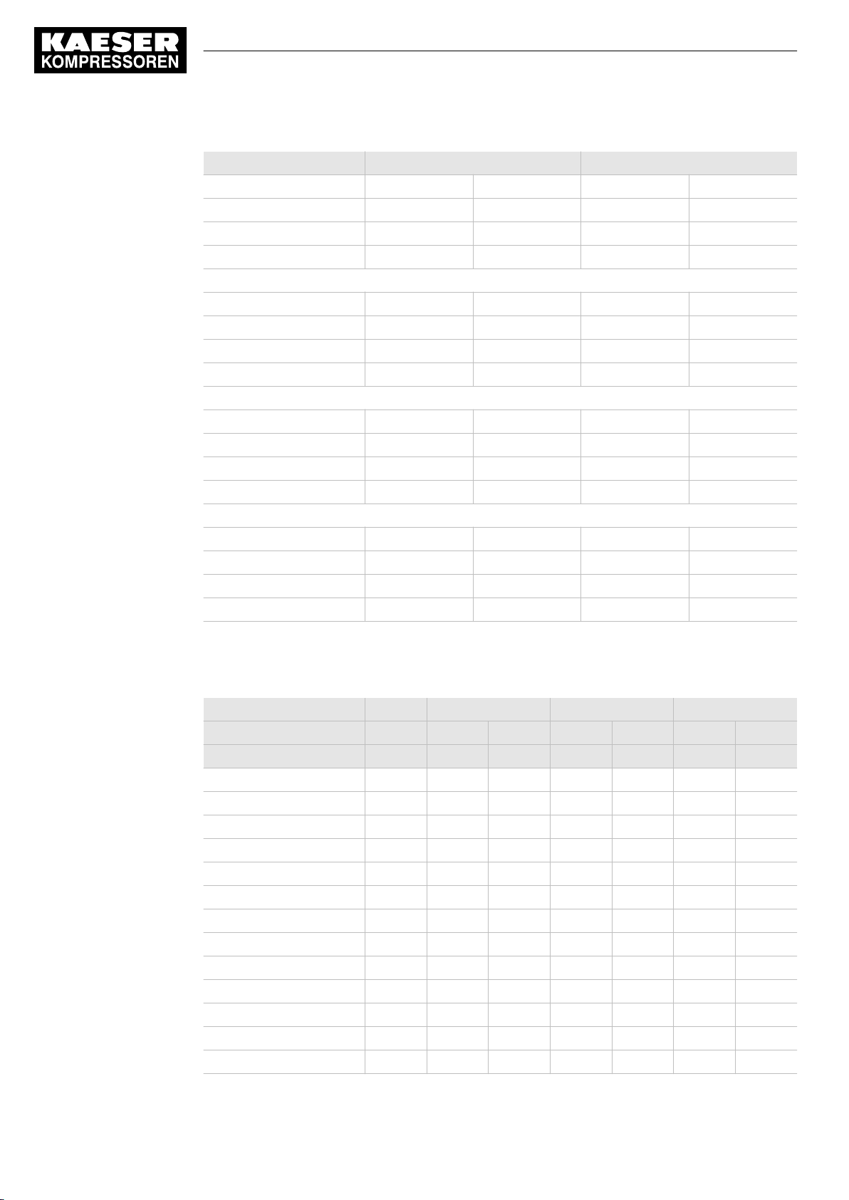
13 Annex
13.5 Machine settings
Machine number Cut-in pressure Cut-out pressure
Machine 1/5/9/13 ON 9.3 OFF 10.0
Machine 2/6/10/14 ON 9.0 OFF 9.7
Machine 3/7/11/15 ON 8.7 OFF 9.4
Machine 4/8/12/16 ON 8.4 OFF 9.1
Maximum working pressure 13 bar:
Machine 1/5/9/13 ON 12.3 OFF 13.0
Machine 2/6/10/14 ON 12.0 OFF 12.7
Machine 3/7/11/15 ON 11.7 OFF 12.4
Machine 4/8/12/16 ON 11.4 OFF 12.1
Maximum working pressure 25 bar:
Machine 1/5/9/13 ON 22 OFF 25
Machine 2/6/10/14 ON 21 OFF 24
Machine 3/7/11/15 ON 20 OFF 23
Machine 4/8/12/16 ON 19 OFF 22
Maximum working pressure 32 bar:
Machine 1/5/9/13 ON 27 OFF 32
Machine 2/6/10/14 ON 26 OFF 31
Machine 3/7/11/15 ON 25 OFF 30
Machine 4/8/12/16 ON 24 OFF 29
Tab. 52 Recommended settings: Pressure range for manual operation
Personal settings
Date/time
Switching point ON OFF ON OFF ON OFF
Unit
Machine1 [bar]
Machine 2 [bar]
Machine 3 [bar]
Machine 4 [bar]
Machine 5 [bar]
Machine 6 [bar]
Machine 7 [bar]
Machine 8 [bar]
Machine 9 [bar]
Machine 10 [bar]
Machine 11 [bar]
Machine 12 [bar]
Machine 13 [bar]
88
Service manual SIGMA AIR MANAGEMENT SYSTEM
SAM 2 No.: 901735 00 E
Page 99
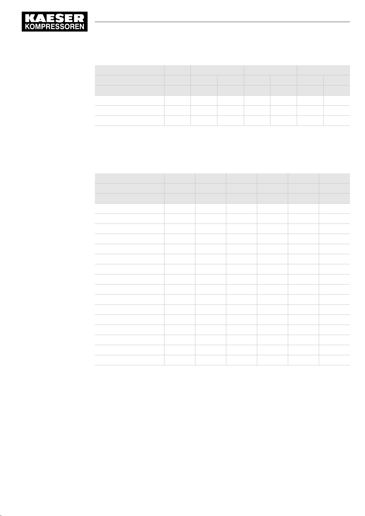
13 Annex
13.5 Machine settings
Date/time
Switching point ON OFF ON OFF ON OFF
Unit
Machine 14 [bar]
Machine 15 [bar]
Machine 16 [bar]
Tab. 53 Personal settings: Pressure range for manual operation
13.5.3 System offset for manual mode
tv = time delay for switching machines on after a power failure
Date/time
Name
Time delay tv [s] tv [s] tv [s] tv [s] tv [s] tv [s]
Machine1
Machine 2
Machine 3
Machine 4
Machine 5
Machine 6
Machine 7
Machine 8
Machine 9
Machine 10
Machine 11
Machine 12
Machine 13
Machine 14
Machine 15
Machine 16
No.: 901735 00 E
Tab. 54 Personal settings: System offset (manual operation)
Service manual SIGMA AIR MANAGEMENT SYSTEM
SAM 2
89
Page 100
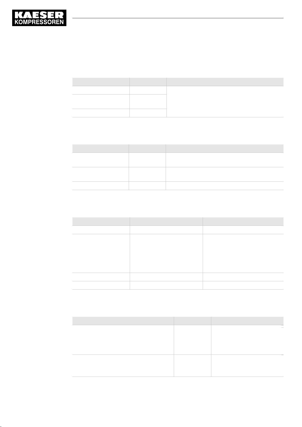
13 Annex
13.6 Installation accessories
13.6 Installation accessories
Communication modules
Name Material number Remarks
PROFINET IO retrofit kit 7.5250.01920 Communication module with accessories, to be instal‐
PROFIBUS DP-V0 Retro‐
fit Kit
Modbus TCP retrofit kit 7.5250.01950
Tab. 55 Communication modules
SIGMA NETWORK
Name Material number Remarks
SIGMA NETWORK cable 7.9679.0 CAT5 2x2x0.64 gr, for indoor installation, PVC coat‐
RJ45 bus connector 7.7628.1 RJ45 plug, 4 insulation displacement/clamping con‐
LAN RJ45 retrofit kit 7.5250.01870 RJ45 bus connector, screw fittings, accessories
7.5250.01880
led by the user, can be retrofitted.
ing, grey, ∅ 6.5 mm, by the metre
tacts, tool-free installation (fast connect)
Tab. 56 SIGMA NETWORK installation accessories
Pressure transducer
Name Material number Pressure range
For model I 7.4599.0 0-1 bar
For model II 7.3397.1
7.2816.3
7.2817.3
7.4762.0
7.6689.0
7.4773.0
For model III 7.7040E3 0-16 bar
For vacuum 7.7046.0 0–1 bar (absolute)
Tab. 57 Pressure transducer
Pressure transducer connection parts and line
Name Material number Remarks
Fitting set straight, elbow G 1/4, G1/2 with
shut-off valve and accessories
up to 16 bar
up to 45 bar
Fitting set G 1/4, G1/2 with shut-off valve and
accessories
up to 15 bar
8.0484.10050
8.0484.00090
204465.0
0–6 bar
0–10 bar
0–16 bar
0–20 bar
0–32 bar
0–45 bar
for air receiver connection
1–litre air receiver for connec‐
tion to pipework
90
Service manual SIGMA AIR MANAGEMENT SYSTEM
SAM 2 No.: 901735 00 E
 Loading...