

Page 1

1000A Precision
Current Shunt
Operation Manual
P/N: 9001000A01 REV: B
Page 2
(PBB)
(PBDE)
O O O
O O O
O O O
O O
O O O O
O O O O O
Package
O O O O O
, PRODIGIT
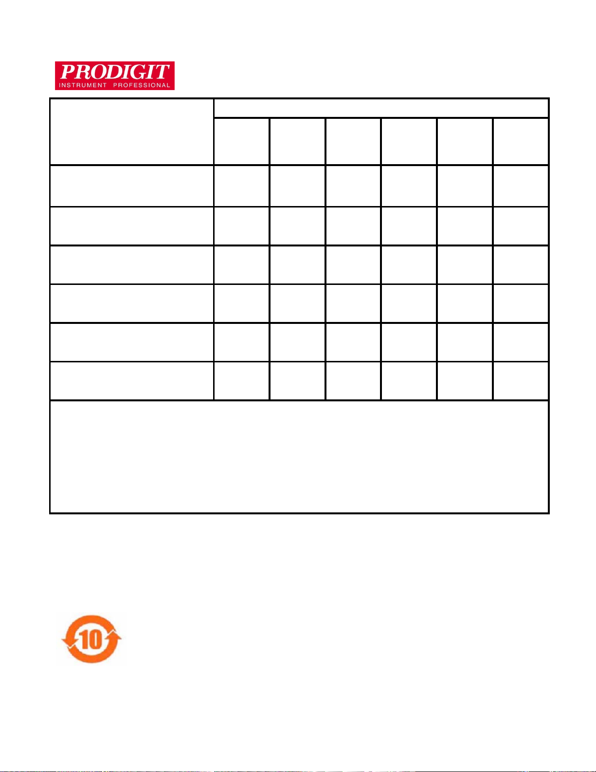
homogeneous materials in the parts is above the relevant threshold of the SJ/T 11363-2006 standard.
(Part Name)
零件名称
Material Content s D eclaration
(材料含量宣称)
Hazardous Substance (有毒有害物质或元素)
铅
(Pb)
汞
(Hg)
镉
(Cd)
六价铬
(Cr6+)
多溴
联苯
多溴
二苯醚
PCBA
(印刷电路装配件)
Electrical part not on PCBA’s
未在PCBA上的电子零件
Metal parts
金属零件
Plastic parts
塑料零件
Wiring
电线
X
X
X
O
O
X
X
X
X X
X
封装
对销售之日的所售产品,本表显示
会也可能不会含有所有所列的部件。This table shows where these s ubstances m ay be found in the suppl y chain
of Prodigit electron ic informat ion products, as of the date of sale of the enclosed pr oduct. Note that some of the
component types liste d above m ay or ma y not be a part of the enclosed produc t. ○:表示该有毒有害物质在该部
件所有均质材料中的含量均在SJ/T 11363-2006 标准规定的限量要求以下。○:Indi cates that the concentratio n of
the hazardous substanc e in all homogeneous mat erials in the parts is below the r elevant threshold of the SJ/T
113632006 standard. ×:表示该有毒有害物质至少在该部件的某一均质材料中的含量超出SJ/T 11363-2006 标准
规定的限量要求。×: Indicates that the concentration of the hazardous substance of at least one of all
供应链的电子信息产品可能包含这些物质。注意:在所售产品中可能
Note(注释):
1.Prodigit has not fully transitioned to lead-free solder assembly at this moment;However, most of the
components used are RoHS compliant.
(此刻,Prodigit 并非完全过渡到无铅焊料组装;但是大部份的元器件一至于RoHS的规定。)
2. The product is labeled with an environment-friendly usage period in years.
The marked period is assumed under the operating environment specified in the product specifications.
(产品标注了环境友好的使用期限制(年)。所标注的环境使用期限假定是在此产品定义的使用环境之下。)
Example of a marking for a 10 year period:
(例如此标制环境使用期限为10年)
Page 3

1000A Precision Current Shunt Operation Manual
Table of Contents
Chapter 1 General information ................................................................................................ 1
1-1. Introduction ........................................................................................................... 1
1-2. Specifications ........................................................................................................ 1
1-3. Accessories ........................................................................................................... 2
1-4. Options .................................................................................................................. 3
Chapter 2 Installation .............................................................................................................. 4
2-1 Check line voltage ................................................................................................. 4
2-2 Input Fuse ............................................................................................................. 4
2-3 Grounding requirements ........................................................................................ 5
2-4 Environmental Requirements ................................................................................ 6
2-5 Observe the International Electrical Symbol Listed Below ..................................... 6
2-6 Cleaning ................................................................................................................ 6
2-7 Power Up .............................................................................................................. 6
2-8 GPIB & RS232 connection option .......................................................................... 7
2-9 RS232 Interface Option ......................................................................................... 7
2-10 GPIB connection option ......................................................................................... 7
2-11 USB connection option .......................................................................................... 8
2-12 LAN Connection Option ......................................................................................... 8
2-13 Range Output ........................................................................................................ 8
Chapter 3 Operation .............................................................................................................. 10
3-1. 1000A current shunt Size description .................................................................. 10
3-2. Front panel description ........................................................................................ 10
3-3. Instructions .......................................................................................................... 11
3-4. Protect ................................................................................................................. 14
Chapter 4 Remote control programming operation ................................................................ 14
4-1. Introduction ......................................................................................................... 15
4-2. The summary of GPIB command ......................................................................... 15
4-3. The summary of RS-232 Interface and command ............................................... 15
4-4. 1000A REMOTE CONTROL COMMAND LIST ................................................... 15
4-5. The description of abbreviation ............................................................................ 16
4-6. Remote Control Command Language description ............................................... 16
4-7. Remote control command description ................................................................. 17
Appendix A 1000A USB Instruction 18
Appendix B: 1000A LAN Installation 21
Page 4
1000A Precision Current Shunt Operation Manual 1
200 A
0.02%
20 A
0.01%
2 A
0.1 Ω
0.01%
2 A
0.01%
Chapter 1 General informat ion
1-1. Introduction
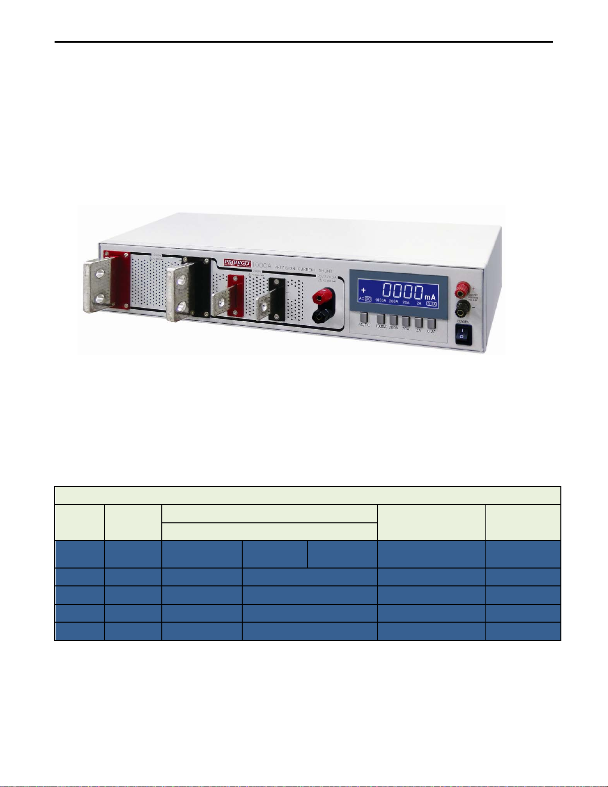
The model 1000A precision current shunt is a precision AC/DC shunt. It incorporates five shunt
ranges from 1Ω, 0.1Ω, 0.01Ω, 0.001Ω to 0.0001Ω. The AC/DC measuring current range from
200mA, 2A, 20A, 200A to 1000A full scale and a built-in 5 1/2 digit precision AC/DC current meter
with AUTO-ZERO and AUTO-RANGE function. Each shunt range has its own a select key
provides access to the voltage output terminals of each shunt resistor. A single set of binding post
conveniently provides output voltage to the measuring voltmeter.
The compliance voltage of the shunt is less than 0.2 volts at full scale for each range except the
1000 Ampere range which has a compliance voltage of 0.1 volts. The shunt is a highly stable
AC/DC resistor connected in a four-terminal non-inductive configuration for each range except the
1000A range.
1-2. Specifications
SHUNT all types are 4 terminal networks with calibration adjustments for each network.
Specifications
Range Shunt Value
1000 A 0.0001 Ω
0.001 Ω
0.01 Ω
0.
1 Ω
DC Accuracy *AC Accuracy
± (% of reading)
0.02% of Reading
+ 0.01% of Range
50/60 Hz
Max input DC/AC rms Output Voltage
0.1%
(Reading + Range)
0.10% 250 A 200A / 0.2V
0.10% 30 A 20A / 0.2V
0.10% 4 A 2A / 0.2V
0.10% 0.4 A 0.2A / 0.2V
1000 A 1000A / 0.1V
Page 5
2 PRODIGIT
DC
*AC
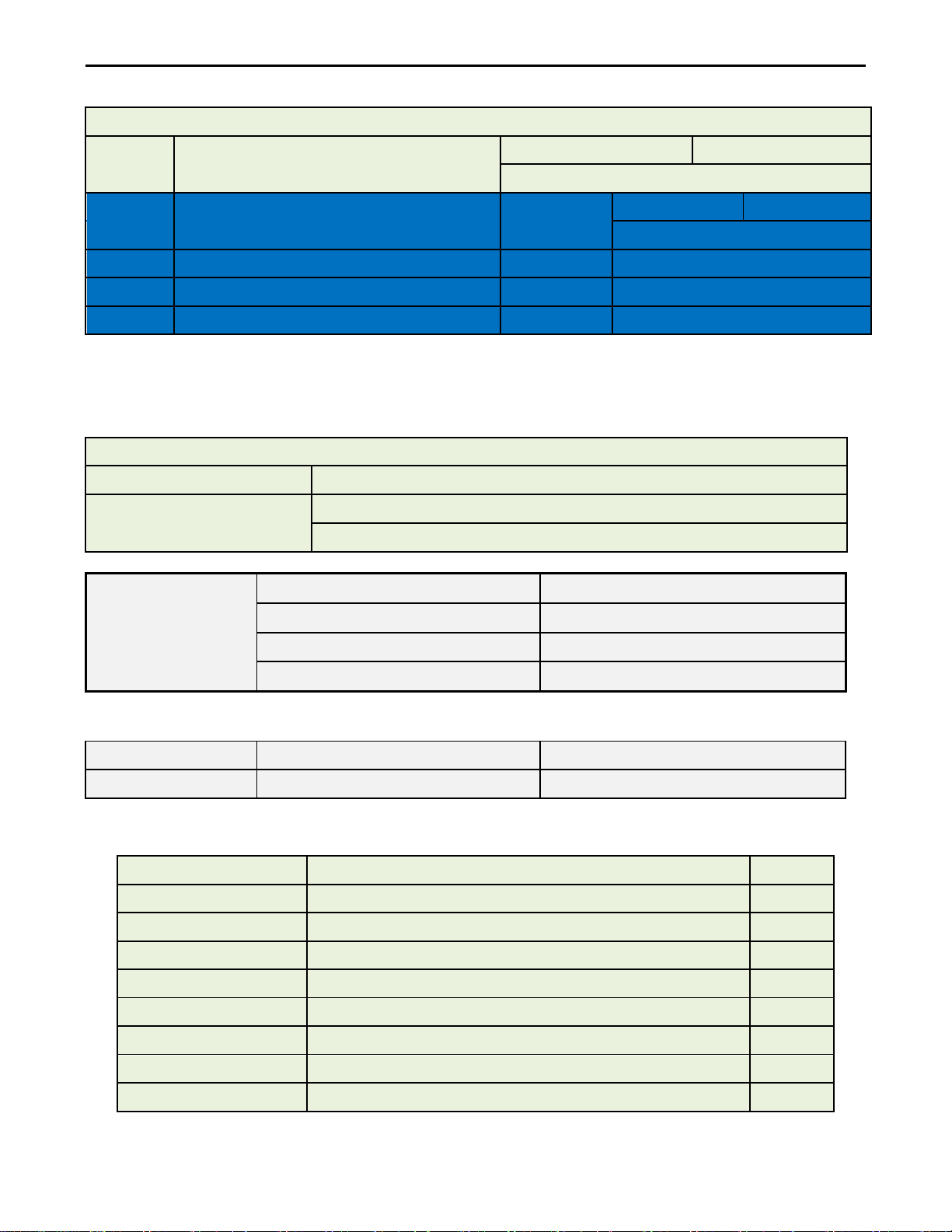
Accuracy ± (% of reading + of Range)
200A
0.001 A~199.999A / 200.00A~250.00A
0.02+0.005
0.5+0.05
20A
0.0001 A~19.9999A / 20.000A~30.000A
0.01+0.005
0.5+0.05
2A
0.01mA~1999.99mA / 2000.0mA~4000.0mA
0.01+0.005
0.5+0.05
0.2A
0.001mA~199.999mA / 200.00mA~400.00mA
0.01+0.005
0.5+0.05
PRODIGIT PART NO.
DESCRIPTIONS
Quantity
60300320
H5.5-8;HOOK TRML YEL INS #12-10
2
60510080
GDL1;FUSE,5X20MM 1.00A, SLOW
1
60550081
GDL5;FUSE ,5X20MM 5.00A SLOW
1
74100351
SCREW M8*1.25 L=35mm NI
4
74109000
RND SCREW M8*1.25 L=35mm NI
4
74500110
NUTS M8X12 X 6
6
74800070
WASHER INSIDE DIA-8.5 *22*1.5 OUTSIDE
12
74100350
SCREW M8*1.25 L=25mm NI
2
Range Resolution
5 1/2 Digit Ampere Meter
0.02+0.01
50/60 Hz
1000A 0.01 A~1000.00 A
*AC input:Range 0.2A、2A、20A、200A ≧ 5% of Range
Range 1000A ≧ 10% of Range
* The specifications apply when the 1000A is powered on for at least 30 minutes
General information’s:
Temperature range:
Temperature coefficient:
0 to 50℃; stated accuracy for 1 year at 23℃±2℃.
Range 0.2A、2A、20A、200A Less than 0.001% per ℃
Range 1000A Less than 0.005% per ℃
LINE 115Vac/ 230Vac ± 10%
FREQUENCY 50/60 Hz
AC INPUT
PROTECT FUSE
0.5+0.1
MAX. POWER CONSUMPTION 25W
Table 1-1 1000A Specifications
Model Dimension(HxWxD) WEIGHT
1000A 89 mm x 440 mm x 370 mm 13.5Kg
Table 1-2 1000A Dimensions
1-3. Accessories
Page 6
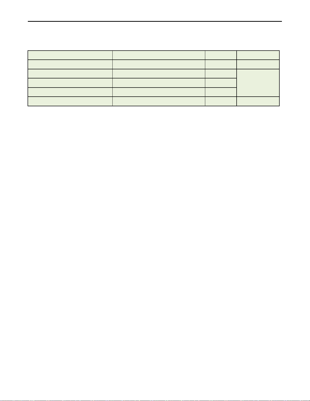
1-4. Options
PRODIGIT PART NO.
DESCRIPTIONS
Quantity
NOTE
64180100
1 meter welding cable 80 SQMM
2
For 200A
709100002
Braided Connector L=1000mm
2
709200002
Braided Connector L=2000mm
2
709300002
Braided Connector L=3000mm
2
15060801
Rack mount kit
1
1000A Precision Current Shunt Operation Manual 3
For 1000A
Page 7
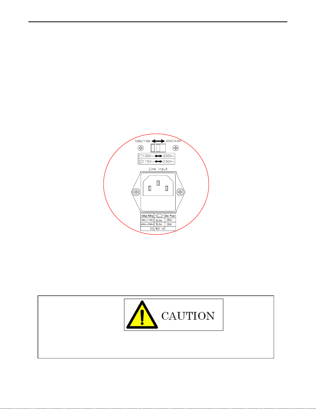
4 PRODIGIT
Chapter 2 Installation
2-1 Check line voltage
The 1000A precision current shunt can be operated from a 100/115 or 200/230Vac input as
indicated on the label on the rear panel. The input is switchable so please make sure that the
switch is set correctly for your nominal mains input before turning on the mains power. The
procedure below details how to change the switch position:
2.1.1 With the 1000A power OFF, disconnect the power cord.
2.1.2 Refer the drawing on the rear panel in Fig 2-1, set the switches to the Proper voltage as described in the following: a. Set Switch to 100V/115V for 115Vac line voltage b. Set Switch to 200V/230V for 230Vac line voltage Note: 100Vac and 200Vac is used for Japan only (Option)
2-2 Input Fuse
This product is fitted with a mains input fuse. If it needs to be replaced please adhere to the
Following procedure.
BEFORE replacing the fuse you must switch off the unit and mains power outlet and
disconnect the plug of the AC Power cable from the input socket of the 1000A.
Fig 2-1 SET OF SWITCH
Page 8
1000A Precision Current Shunt Operation Manual 5
safety standards. Any use of improper fuse or shorting the Fuse holder would be
If prior to exchanging the fuse, there is any abnormal noise or odour do not use the
unit. Please inform your local sales office to organise repair of the 1000A.
To avoid the risk of fire or electronic shock the fuse must only be replaced with same
type and rating as the original. Any replacement fuse used should meet your national
extremely dangerous and would be strictly prohibited.
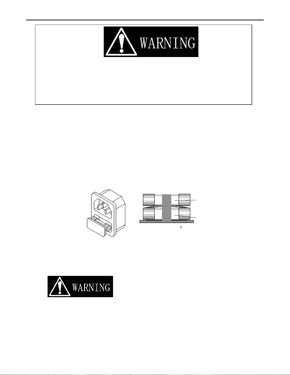
2.3.1 Check the rating of the mains input fuse. Replace only with the correct Type and rating.
For 100V/115Vac Input use T0.5A/250V (5*20mm),
For 200V/230Vac Input use T0.5A/250V (5*20mm)
2.3.2 The AC line fuse is located below the AC line socket (see Fig 2-2). Use
A small screwdriver to remove the fuse holder. Replace the failed fuse
With the appropriate type and rating according to your mains voltage.
(See Table 1-1)
2.3.3 Refit the fuse holder and connect the power cord.
T0.5A/250V (5*20mm)
T0.5A/250V (5*20mm)
Fig 2-2 FUSE RECEPTACLE
2-3 Grounding requirements
SHOCK HAZARD
The unit is grounded via the AC Input. It must be ensured that the correct mains lead with earth
pin is used. Correct grounding of your electrical system infrastructure according to national
standards must also be observed.
Page 9

6 PRODIGIT
2-4 Environmental Requirements
• Indoor use.
• Insulation Category I.
• Pollution Degree 2.
• Altitude up to 2000 meters
• Relative Humidity 80% Max (non-condensing).
• Ambient Temperature 0 to 40°C
• The ideal operating temperature is 25°C ± 5°C
2-5 Observe the International Electrical Symbol Listed Below
Warning!Risk of electric shock.
Caution!Refer to this manual before using the instrument.
2-6 Cleaning
To clean this product uses a soft or slightly damp cloth.
BEFORE you clean the unit, switch the mains power off and disconnect the input lead.
・ Please do NOT use any organic solvent capable of changing the nature of the plastic
such as benzene or acetone.
・ Please ensure that no liquid is allowed to penetrate this product.
2-7 Power Up
The following procedure should be followed before applying mains power:
The following procedure should be followed before applying mains power:
• Check that the POWER switch is in the off (O) position
• Check the rear panel voltage selector of the 1000A is correctly set.
• Connect correct AC mains lead to the 1000A
• Turn on (I) the POWER switch.
Page 10
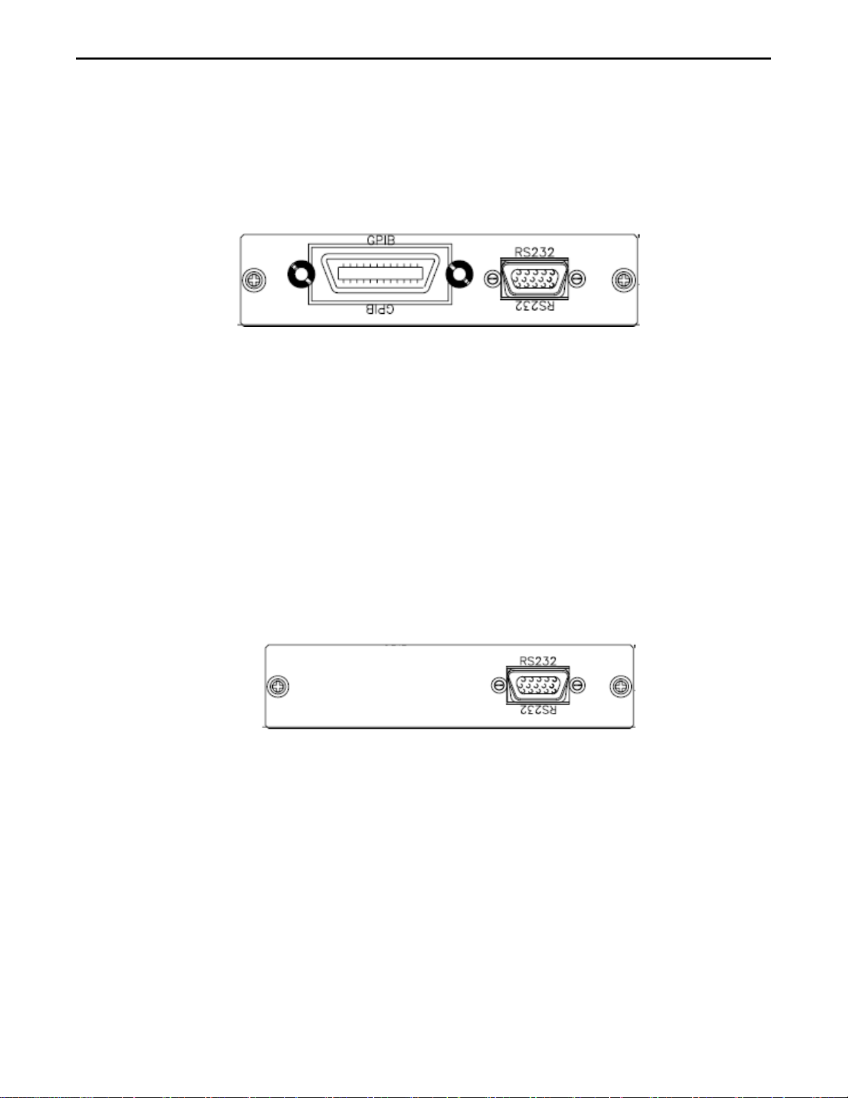
2-8 GPIB & RS232 connection option
If your 1000A is fitted with GPIB + RS232 interface card then the rear panel will have the
necessary interface sockets as shown in Fig 2-3. This connects the 1000A mainframe to
RS232 or GPIB port of your computer.
GPIB and RS232 interface can only be used at the same time, to Change the interface must
reboot unit.
Fig 2-3 1000A REAR PANEL
A GPIB system can be connected in any configuration (star, linear, or both) as long as
• The maximum number of devices including the controller is no more than 15.
• The ma x i mum length of the GPIB cable is no more than 2 meters.
• The total lead length of all devices connected together total <20 meters
• Setting GPIB address:
Hold AC/DC Key 3 Second.→ Pass 2A Key or 20A Key to change the address
→ Pass AC/ DC Key to save the new address.
1000A Precision Current Shunt Operation Manual 7
2-9 RS232 Interface Option
Fig 2-4 s hows the RS232 connector (Female) on the rear panel. This connects the 1000A to
RS232 port of computer.
Fig 2-4 1000A RS232 Connection
2-10 GPI B connection option
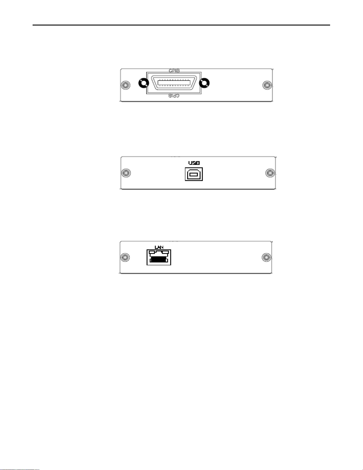
The GPIB connector is located on the rear panel. This socket allows the 1000A to be
connected to the controller and other GPIB devices. A GPIB system can be connected in any
configuration (star, linear, or both) as long as
• The maximum number of devices including the controller is ≤15.
• The ma x i mum length of the GPIB cable is no more than 2 meters times.
• The total lead length of all devices connected together total <20 meters.
• Please make sure the lock screws are firmly hand-tightened, use a
Screwdriver only for the removal of screws. Fig 2-5 shows the rear
Panel of 1000A mainframe, The GPIB address of the 1000A mainframe
is set on Front panel.
Page 11
8 PRODIGIT
• Setting GPIB address:
Hold AC/DC Key 3 Second.→ Pass 2A Key or 20A Key to change the address
→ Pass AC/ DC Key to save the New address
Fig 2-5 1000A REAR PANEL
2-11 USB connection option
Fig 2-6 shows the USB connector in the rear panel of 1000A mainframe. Please refer Appendix A.
Fig 2-6 1000A USB Connection
2-12 LAN Connection Option
Fig 2-7 shows the LAN connector in the rear panel of 1000A mainframe. Please refer Appendix B.
Fig 2-7 1000A LAN Connection
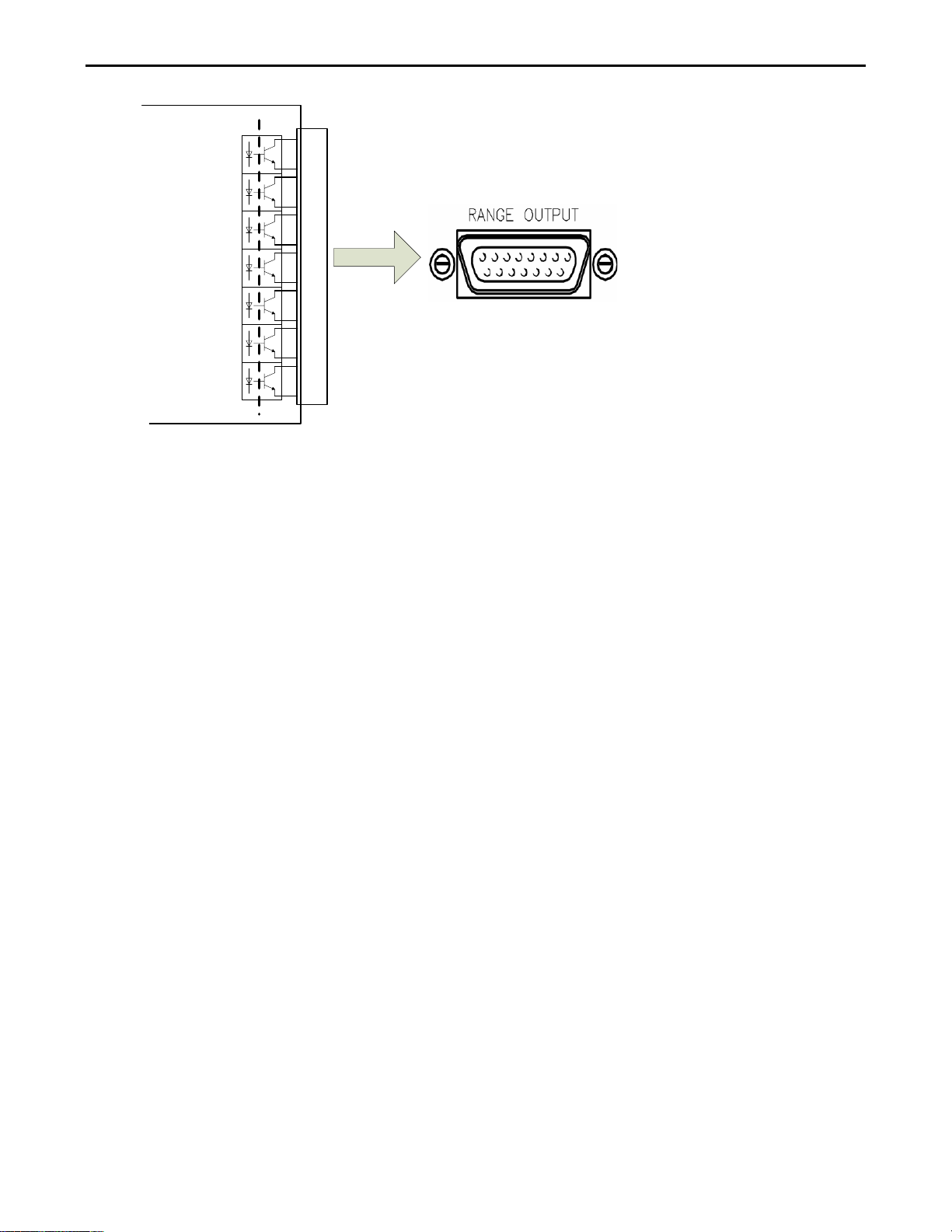
2-13 Range Output
The RANGE OUTPUT connector of 1000A rear panel,
Pin 1, 2: AC/DC (On: AC, OFF: DC)
Pin 3, 4: POS/NEG (On: NEG, OFF: POS)
Pin 5, 6: 0.2A (On: Range 0.2A)
Pin 7, 8: 2A (On: Range 2A)
Pin 9, 10: 20A (On: Range 20A)
Pin 11, 12: 200A (On: Range 200A)
Pin 13, 14: 1000A (On: Range 1000A)
Pin 15: Reserved
Page 12
1000A Precision Current Shunt Operation Manual 9
Pin
1
Pin2
1000
A
IF = 5mA
PC
817
Pin
3
Pin
4
Pin5
Pin
6
Pin
7
Pin
8
Pin
9
Pin
10
Pin
11
Pin
12
Pin
13
Pin
14
Fig 2-8 RS-232C RANGE OUTPUT CONNECTIO N OF REAR P ANEL
Page 13
10 PRODIGIT
Chapter 3 Operation
This chapter describes the front panel function and operation of each 1000A current shunt, and
GPIB/RS232/LAN/USB programming.
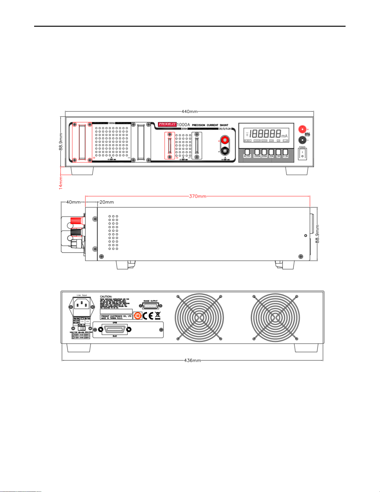
3-1. 1000A current shunt Size description
Fig 3-1 1000A SIZE description
3-2. Front panel description
Page 14
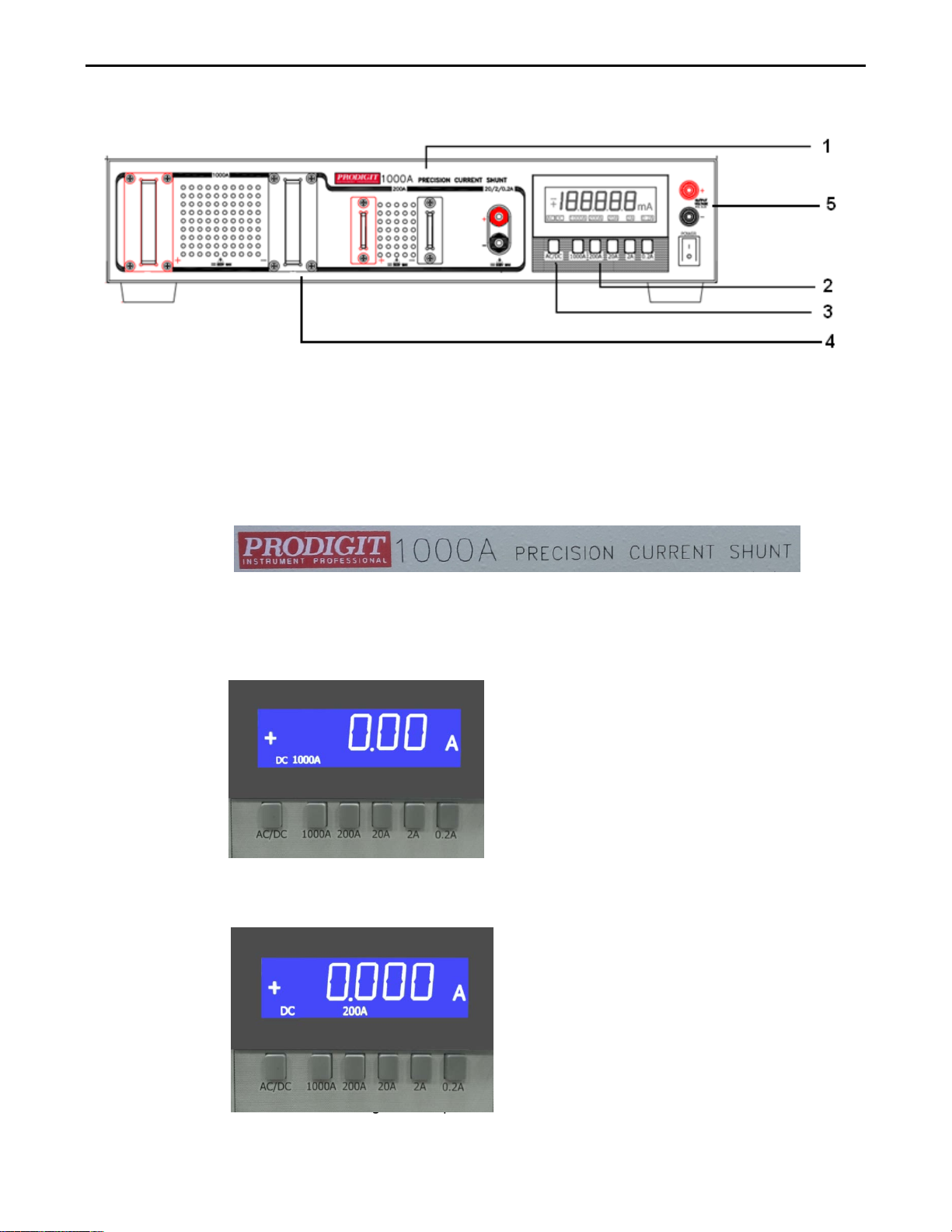
The following sketch shows the layout of the front panel of the unit. Please refer to the
relevant section as indicated by the number assigned to a front panel function.
3-3. Instructions
3.3.1. Model number and sink ranges
The model number along with maximum current values is detailed in this position
At the top of the current shunt front panel.
It indicates the model number and specifications of 1000A Current shunt.
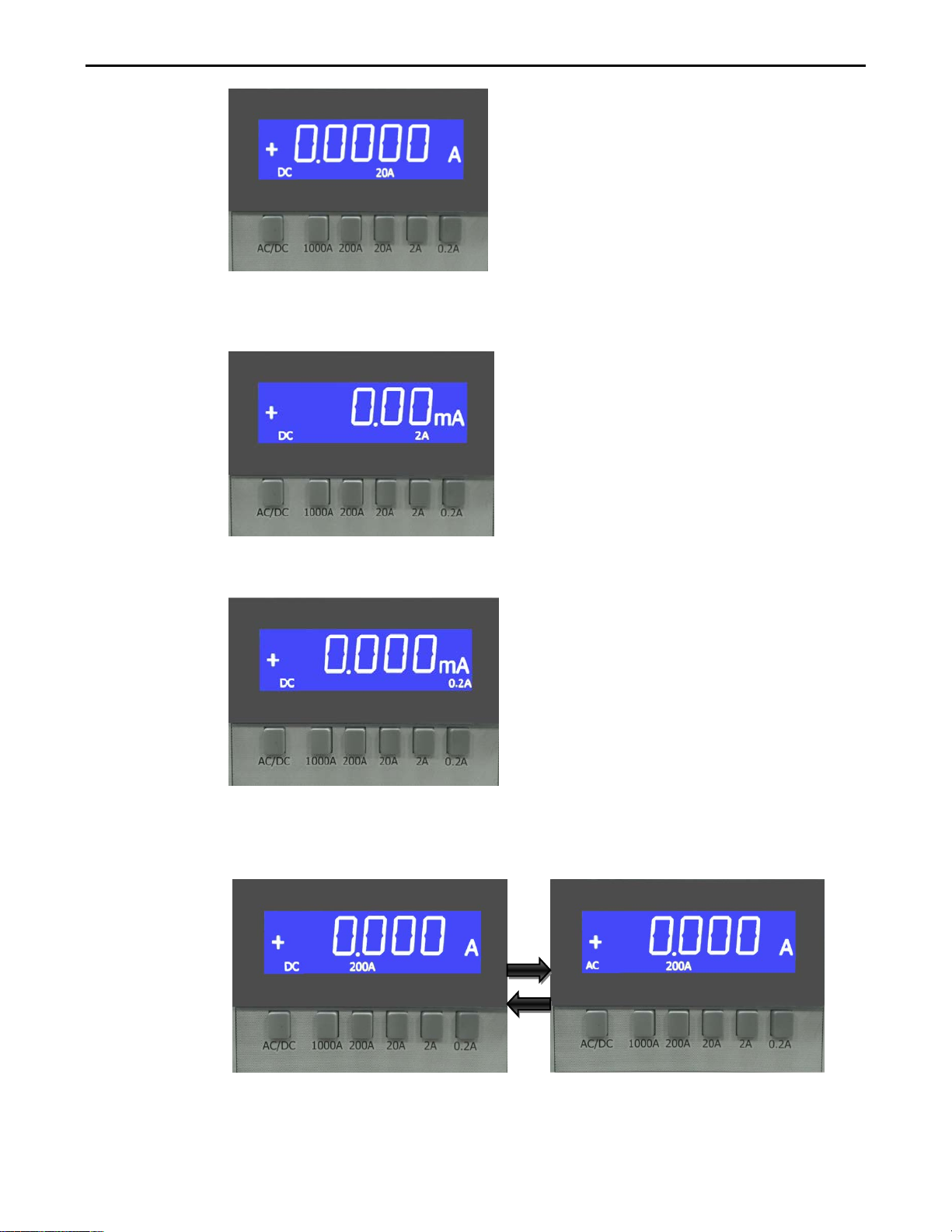
3.3.2. Range Select
There are five operating range, the sequence is 1000A, 200A, 20A, 2A, 0.2A.
Pressing the "1000A" key on the 1000A current Shunt, the appropriate LCD will
Illuminate according to the operating range is selected.
1000A Precision Current Shunt Operation Manual 11
Pressing the "200A" key on the 1000A current Shunt, the appropriate LCD will
Illuminate according to the operating range is selected.
Pressing the "20A" key on the 1000A current Shunt, the appropriate LCD will
Illuminate according to the operating range is selected.
Page 15
12 PRODIGIT
Pressing the "2A" key on the 1000A current Shunt, the appropriate LCD will
Illuminate according to the operating range is selected.
Pressing the "0.2A" key on the 1000A current Shunt, the appropriate LCD will
Illuminate according to the operating range is selected.
3.3.3. AC/DC Select key
Pressing the "AC/DC" key on the 1000A current Shunt, the appropriate LCD will
Illuminate according to the operating AC or DC mode is selected.
3.3.4. Current measurements
The 1000A use a four terminal current shunt configuration. Two terminals
Page 16
1000A Precision Current Shunt Operation Manual 13
(CURRENT INPUT) are connecting the load in series with the panel terminals of
the appropriate current shunt. Note the maximum current limit label on the panel.
The RANGE selector key-switch is used to select the voltage sense terminals
(VOLTAGE OUTPUT) and the 5 1/2 digit precision current meter. The VO LTAGE
OUTPUT sense terminal and the 5 1/2 digit precision current meter are connected
directly across the calibration adjustment divider of the shunt resistor selected by
the RANGE key-switch.
3.3.5. Output
To measuring the load current can〝direct reading〞from 5 1/2 digit precision
AC/DC current meter in normally application. For the higher accuracy & resolution
Application, the OUTPUT voltage can be measured with a measuring device
(Thermal transfer standard, 6 1/2) precision DVM, etc).
It is not necessary that a load connected to one range be disconnected when
connecting a load to another range as the range key-switch isolates the shunts
from one another.
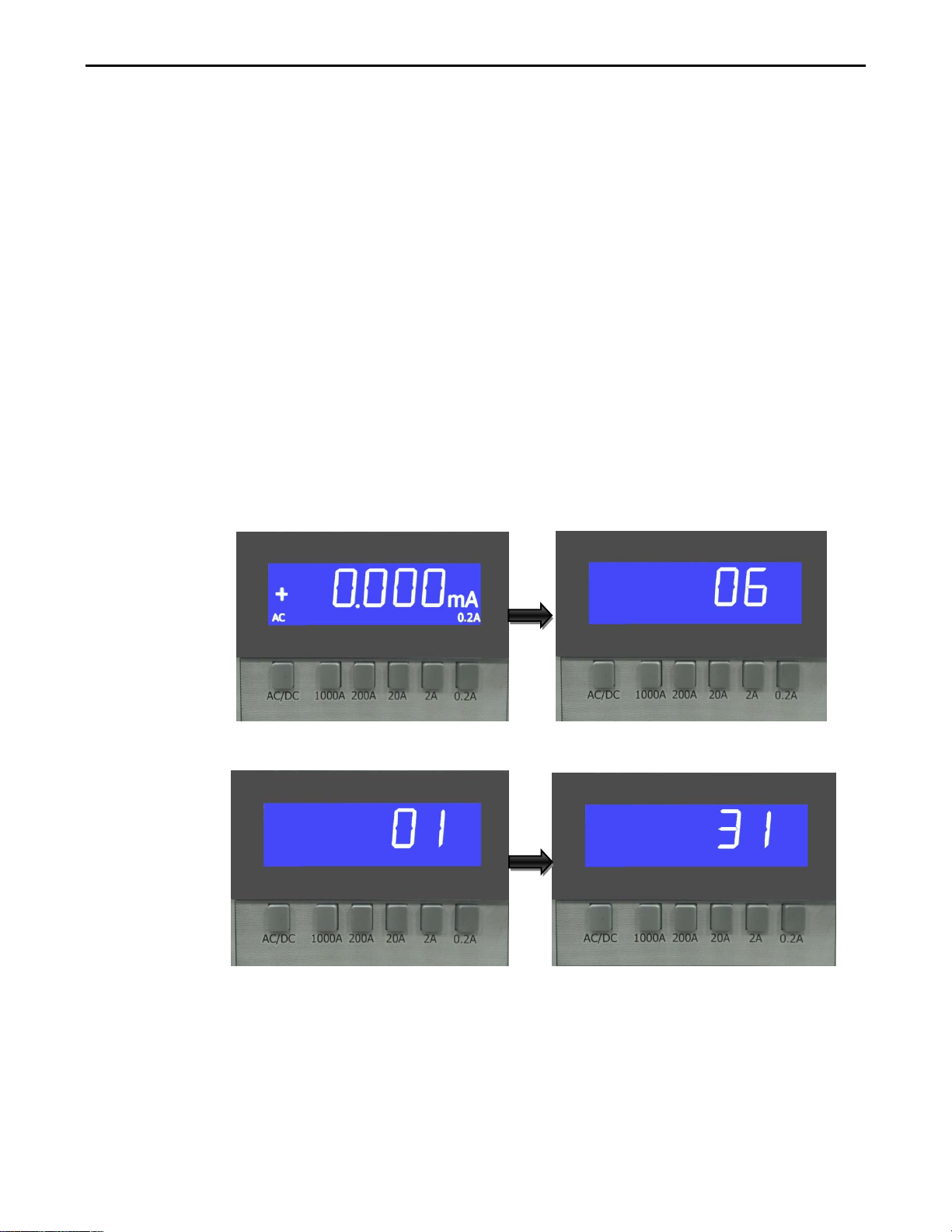
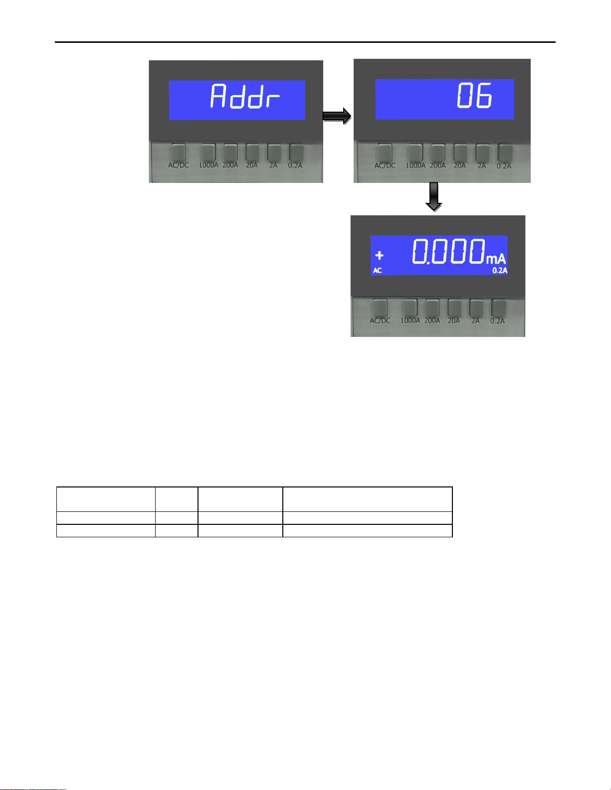
3.3.6. Setting GPIB Address
Set the GPIB address you must press the AC/DC key three second. The
LCD will display the current address.
Note: GPIB initial value of 06
Press 2A (UP), 20A (down) buttons to adjust the GPIB address 1 to 31.
Once the required address is reached press AC/DC key to save the New
Address and return to the normal screen.
Page 17
14 PRODIGIT
PRODIGIT PART
NO.
REF.
RANGE
DESCRIPTIONS
60510080
F2
200mA
1.0 A/250 V 5×20mm Slow Blow
60550081
F3
2 A
5.0 A/250 V 5×20mm Slow Blow
3-4. Protect
The protect device (current fuse) protects the 200mA and 2A range from an input current greater
than 1A and 5A. To replace the current fuse, perform the following steps:
1. Turn off the power and disconnect all equipment.
2. Remove the top cover of instrument to replace the fuse. Top cover is removed by removing
four screws.
3. Remove the defective fuse and replace it with the recommended fuse.(See table 3-1) or
equivalent.
Table 3-1 recommended fuse
CAUTION:Use only the recommended fuse type. If a fuse with a higher current rating
is installed, instrument damage may occur.
Chapter 4 Remote control programming operation
Page 18
1000A Precision Current Shunt Operation Manual 15
4-1. Introduction
The rear panel GPIB/RS-232 interface of 1000A mainframe is designed to connect PC or
NOTEBOOK PC with GPIB/RS-232 interface, the NOTEBOOK PC acts as a remote
controller of 1000A precision current shunt.
4-2. The summary of GPIB command
There’re two syntax commands of 1000A to be selected. One is SIMPLE mode and the other
is COMPLEX mode.
4-3. The summary of RS-232 Interface and command
The following RS-232 commands are same as GPIB commands. The RS-232 protocol in
1000A mainframe is listing below:
Baud-rate :115200 bps
Parity :None
Data bit :8 bits
Stop bit :1 bit
Handshaking :Hardware (RTS/CTS).
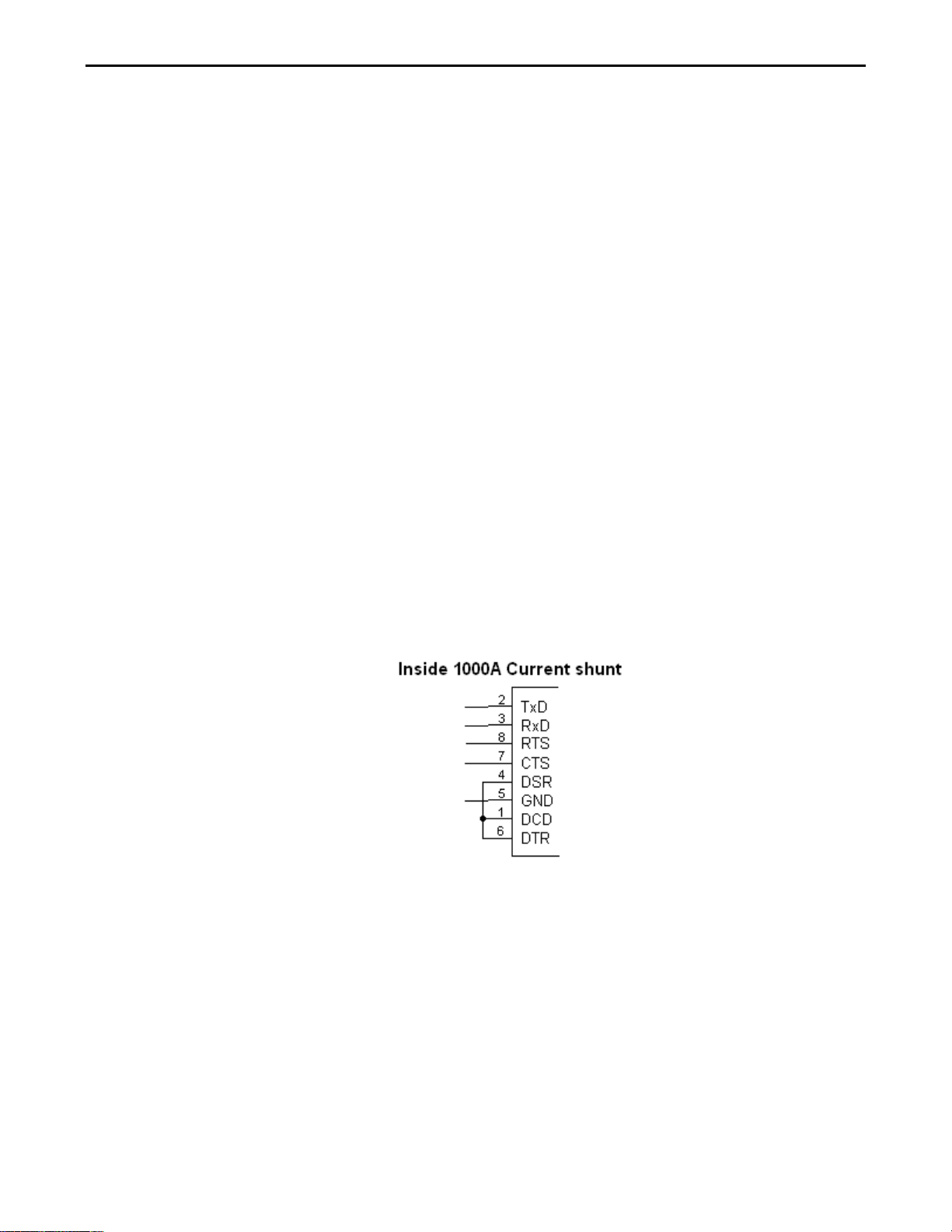
The RS-232C Interface connector of 1000A rear panel, RS-232 is shown in Fig4-1.
Fig 4-1 RS-232C INTERFACE CONNECTION OF REAR PANEL
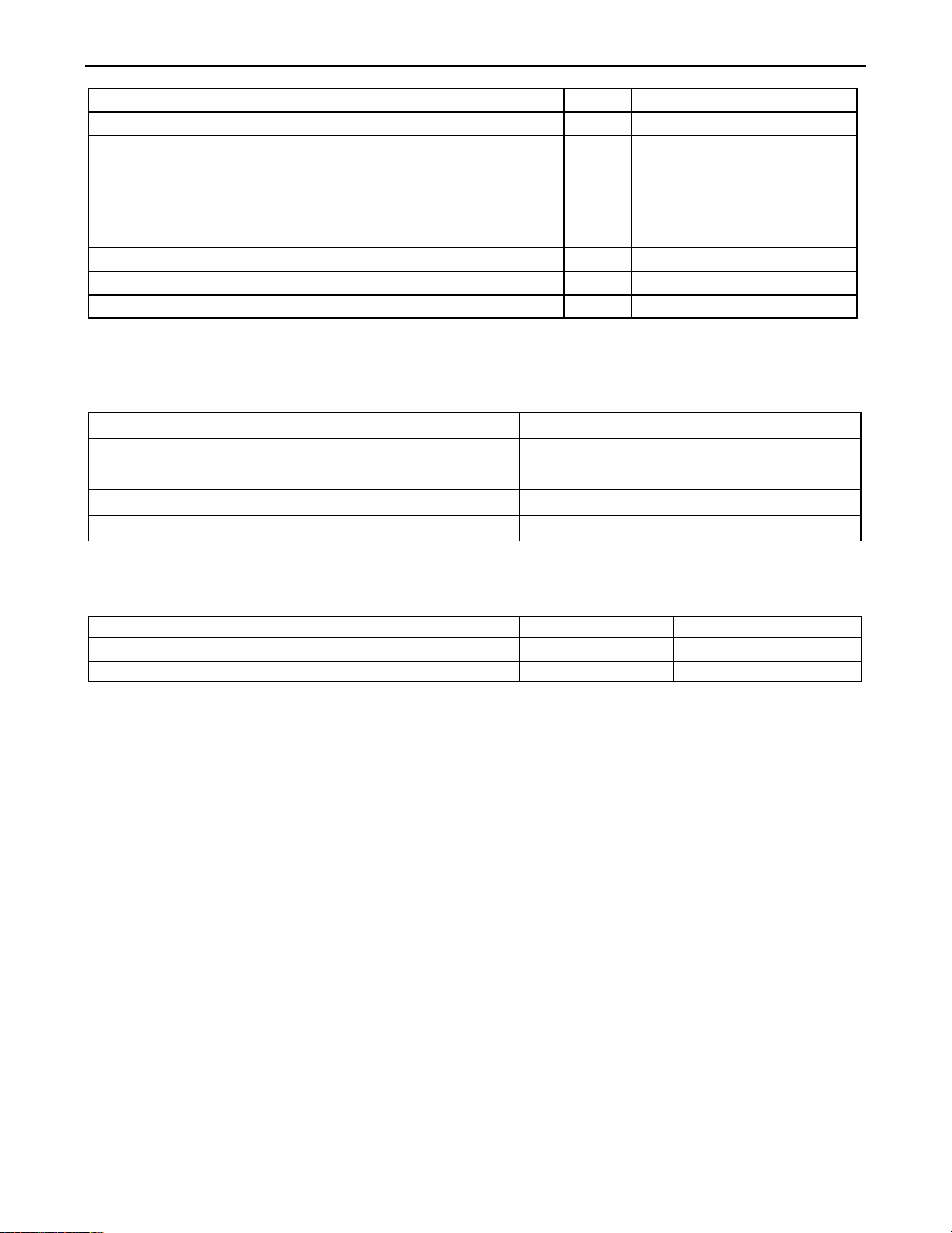
4-4. 1000A REMOTE CONTROL COMMAND LIST
COMPLEX TYPE FORMAT
Page 19
16 PRODIGIT
State Commands
NOTE
RETURN
[STATe] RANGe{SP}{0.2A│2A│20A│200A│1000A} (
│NL)
0:0.2A
4:1000A
[STATe
] MODE{SP}{DC│AC} (
│NL)
[STATe:] MODE{?}(;│NL)
‘0’:DC ‘1’:AC
[ SYStem:] REMOTE(;NL)
Only RS232cmd
[ SYStem:] LOCAL(; NL)
[ SYStem:] NAME {?} (; NL)
“PRODIGIT:1000A”
Measure Commands
NOTE
RETURN
MEASure:CURRent{?}(;NL)
{####.####}[m]{A}
[STATe] RANGe{?} (;│NL)
;
1:2A
2:20A
3:200A
:
;
TABLE 4-1 STAGE COMMAND SUMMARY
System Commands NOTE RETURN
Only RS232cmd
TABLE 4-2 SYSTEM COMMAND SUMMARY
TABLE 4-3 MEASURE COMMAND SUMMARY
4-5. The description of abbreviation
SP:Space, the ASCII code is 20 Hexadecimal.
; :Semicolon, Program line terminator, the ASCII code is OA Hexadecimal.
NL:New line, Program line terminator, the ASCII code is OA Hexadecimal.
NR2:Digits with decimal point. It can be accepted in the range and format of###.#####.
For Example:
30.12345, 5.0
The description of GPIB programming command syntax.
4-6. Remote Control Command Language description
{ } : The contents of the { } symbol must be used as a part or data of the GPIB
Page 20

1000A Precision Current Shunt Operation Manual 17
LF
LF WITH EOI
CR,LF
CR,LF WITH EOI
0
0.2A
1
2A
2
20A
3
200A
4
1000A
command, it can not be omitted.
[ ] : The contents of the [ ] symbol indicts the command can be used or not. It
depends on the testing application.
| : This symbol means option. For example〝LOW|HIGH〞means it can only use
LOW or HIGH as the command, it can choose only one as the setting
command.
Terminator : You have to send the program line terminator character after send the GPIB
command, the available command terminator characters which can be
accepted in 1000A mainframe is listed in Table 4-4.
TABLE 4-4 GPIB COMMAND TERMINATOR
4-7. Remote control command description
[STATe ] RANGe
Syntax:[STATe] RANGe{SP}{0.2A│2A│20A│200A│1000A} (;│NL)
Purpose: Set the 1000A Current shunt range.
Description: This command is set the 1000A Current shunt range.
[STATe] RANGe{?}
Syntax:[STATe] RANGe?
Purpose read the 1000A Current shunt range.
Description:This c ommand is read the 1000A Current shunt range.
[STATe ] MODE
Syntax [STATe:] MODE{SP}{DC│AC} (;│NL)
Purpose: Set the 1000A Current shunt AC or DC mode.
Description: This command is set the 1000A Current shunt AC or DC mode.
[STATe ] MODE?
Syntax [STATe:] MODE?( ;│NL)
Page 21
18 PRODIGIT
0
DC
1
AC
MODEL
PRODIGIT:1000A
Purpose: Read the 1000A Current shunt AC or DC mode.
Description: This command is read the 1000A Current shunt AC or DC mode.
.
[SYStem:] NAME?
Syntax:[SYStem:] NAME? {;NL}
Purpose: Read the model number of Load
Description: This command is for reading the model number of Load. If no module is
Operating, the display will be lit “NULL”, or it will be lit the model number
as table 4-5
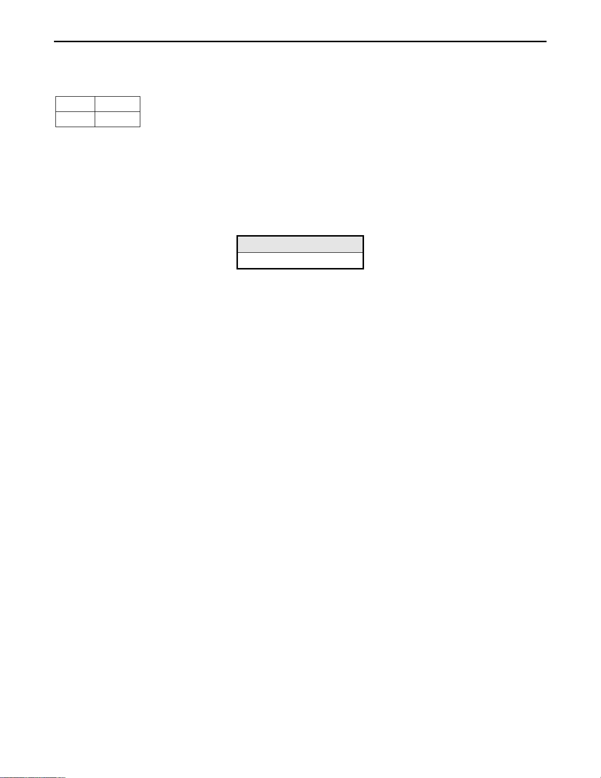
TABLE 4-5
[SYStem:] REMOTE
Syntax: [SYStem:] REMOTE {;NL}
Purpose:Command to enter the REMOTE status (only for RS232)
Description:This command is for controlling the RS232
[SYStem:] LOCAL
Syntax:[SYStem:] LOCAL {;NL}
Purpose:Command to exit the REMOTE status (only for RS232)
Description:This command is for finishing the RS232
MEASure:CURRent?
Syntax:MEASure:CURRent?{;NL}
Purpose:Read the current which is loading of Load
Description:Read the five numbers of current meter, and the unit is Ampere(A)
Appendix A 1000A USB Instruction
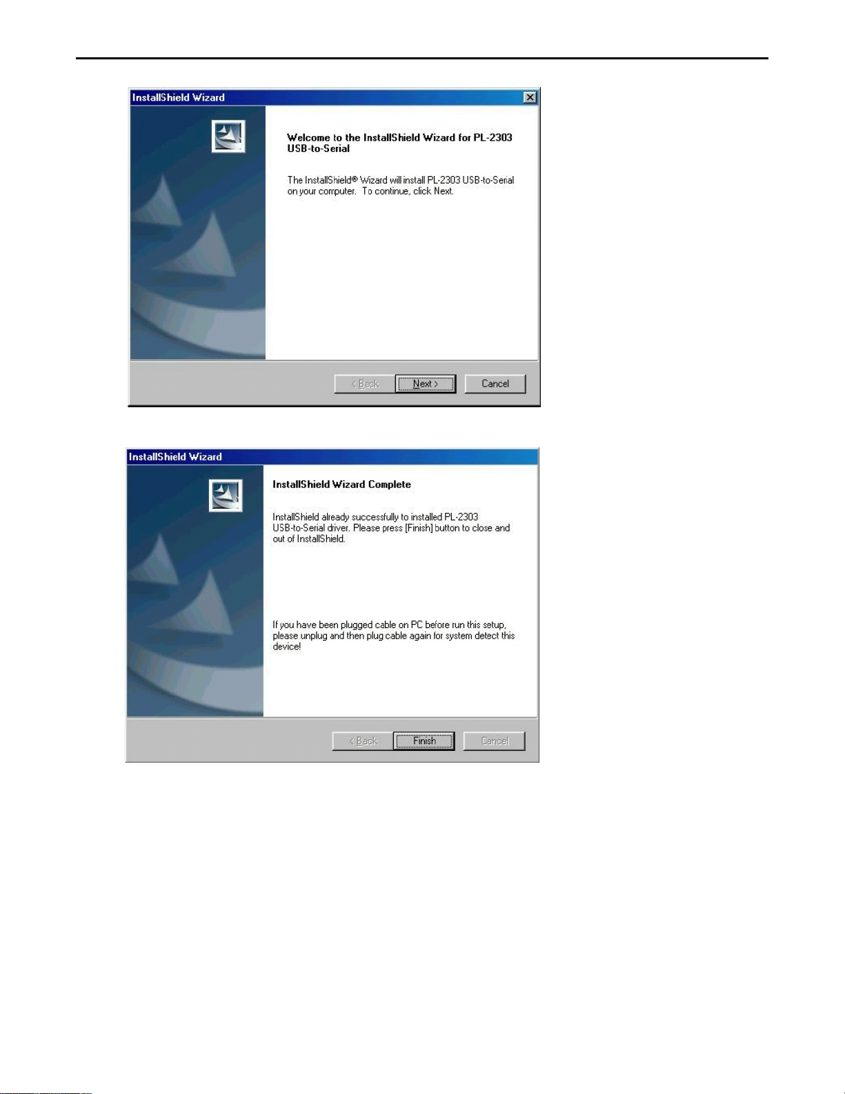
1. Install the USB DRI V ER, select USB\SETUP\PL-2303 Driver Installer.exe.
Page 22
1000A Precision Current Shunt Operation Manual 19
Page 23
20 PRODIGIT
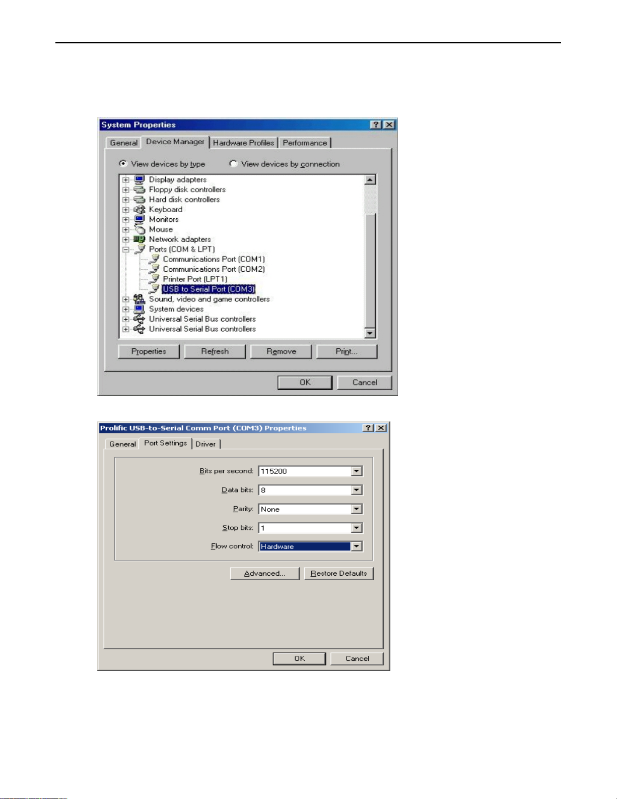
2. After the installation, connect the 1000A and PC with USB. Then select the item U SB to Serial
Port (COM3), set the BAUD-RATE to 115200bps and the Flow control to Hardware. You should
then be able to control the 1000A via USB on COM3.
Page 24
1000A Precision Current Shunt Operation Manual 21
Appendix B: 1000A LAN Installation
1. Connect AC power and the network (LAN) cable to the 1000A mainframe. Connect the other side of
the network cable to the existing network.
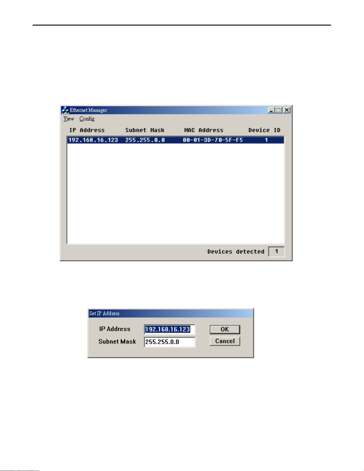
2. After inserting the driver CD-ROM, run LAN\ETM.EXE from the CD. The Ethernet Manager screen
will be displayed as shown in Fig C1-1. If the Ethernet Manager window does not appear then, press
F5 to search again (refresh), and check the connections if necessary.
Fig D2-1
3. The connected unit will appear on the list, click it to set the IP Address and Subnet Mask as
shown on the following figure.
Page 25
22 PRODIGIT
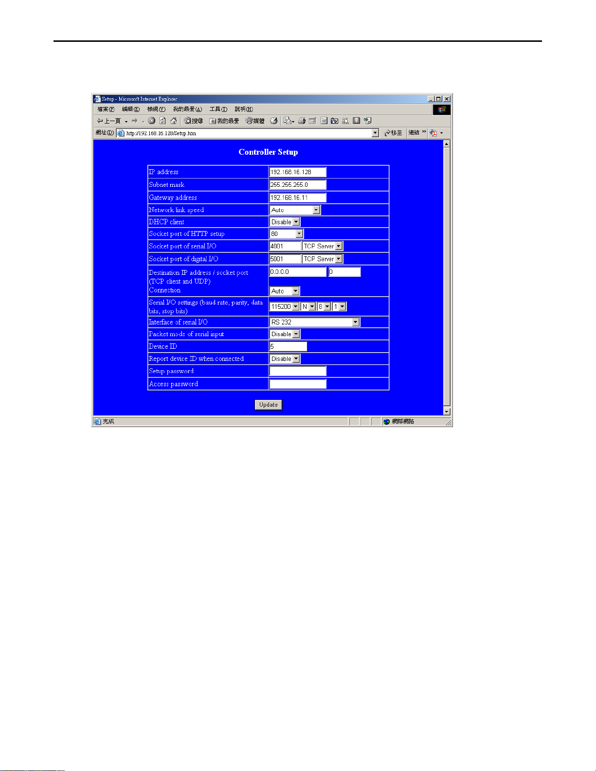
4. The Controller Setup page should be accessible, once everything is set correctly. This allows
greater control over the communications interface.
5. Insert the following into the controller set up screen:
a) IP Address: as recommended according to your network
b) Subnet Mask: as recommended according to your network
c) Gateway Address: as recommended according to your network
d) Network link speed: Auto
e) DHCP client: Disable
f) Socket port of HTTP setup: 80
g) Socket port of serial I/O: 4001
h) Socket port of d ig ital I/O: 5001
i) Destination IP address / socket port (TCP client and UDP) Connection: Auto
j) Serial I/O settings (baud rate, parity, data, bits, stop bits): 115200, N, 8, 1
k) Interface of s erial I/ O : RS 232
l) Packet mode of serial input: Disable
m) Device ID : 5
n) Setup password: Not required
o) Access password : Not required
 Loading...