


9.0 DRO ROTOR MATCHING SYSTEM
TECHNICAL MANUAL
9.0 DRO Rotor Matching System
TECHNICAL MANUAL
phone: 800.543.6618 fax: 603.298.8404
email: info@procutusa.com web: www.procutusa.com

OUR MISSION
Pro-Cut International is dedicated to providing our customers with the most advanced, precise, and profitable tools for brake repair. We have worked with, learned from and solved problems for people at all levels of the brake repair business - from the largest auto manufacturers and national service chains to one-bay, one-man operations. It is a business our entire staff lives, eats, and breathes. We welcome you to our table and look forward to working with you to improve your brake service business.
PG / ØØ4 800.543.6618

Limited Warranty
This warranty extends to the original owner of the the equipment. Pro-Cut International warranties this equipment against defects in materials or workmanship as follows.
Labor
For the period of one (1) year from the original date of purchase, if we determine that the equipment is defective subject to the limitations of this warranty, we will replace it at no charge for labor. Pro-Cut International warrants any such work done against defects in materials or workmanship for the remaining portion of the original warranty period.
Parts
For the period of one (1) year from the original date of purchase, we will supply, at no charge, new or rebuilt replacement parts in exchange for parts we determine are defective subject to the limitations of this warranty. Pro-Cut International warranties any such replacement parts against defects in materials or workmanship for the remaining portion of the original warranty period.
What Your Warranty Does Not Cover
This warranty does not apply to damage due directly to misuse, abuse, negligence or lack of maintenance.
WWW.PROCUTUSA.COM PG / ØØ5

|
CONTENTS |
|
|
|
4 |
Pro-Cut Mission |
29 |
Maintenance |
|
7 |
Safety and Warning Information |
30 |
Troubleshooting: Assuring a Smooth Finish |
|
8 |
Introduction |
33 |
Troubleshooting: Lateral Run-out Adjustment |
|
10 |
Lateral Run-out Defined |
34 |
Troubleshooting: Raising or Lowering the Acceptance Number |
|
12 |
9.0 DRO Lathe Overview |
36 |
DRO Compensation Instructions |
|
14 |
Lathe Setup |
40 |
Adapter Guide |
|
16 |
Vehicle Preparation |
42-49 9.0 DRO Parts Diagrams |
||
18 |
Lathe Preparation: Checking Cutting Tips |
|
9.0 DRO Lathe Body |
|
19 |
Machining Rotors: A 4 Step Guide |
|
9.0 DRO Lathe Body |
|
|
|
|
50-235 Cutting Head |
|
|
Step 1: Mount the Adapter |
|
50-238 |
Cutting Head |
|
Step 2: Set Up the Lathe |
|
50-139 |
Bevel Gear Box |
|
Step 3: Adjust for Lateral Run-out |
|
50-380 |
Trolley |
|
Step 4: Make the Cut |
|
50-390 |
Trolley |
|
|
|
50-1165 Computer Box |
|
27 |
Machining the Opposite Side |
|
50-1730 Spindle Guard |
|
28 |
Vehicle Reassembly |
50 |
Maintenance Schedule |
|
PG / ØØ6 800.543.6618

IMPORTANT SAFETY INSTRUCTIONS
The 9.0 DRO Rotor Matching System is a precision instrument which requires close attention while in operation. It will provide many years of service if it is operated safely. Basic Safety precautions should always be followed, including the following:
1.Read all instructions
2.Care must be taken as burns can occur from touching hot parts.
3.Do not operate equipment with a damaged cord or if the equipment has been dropped or damaged - until it has been examined by a qualified service person.
4.Do not let a cord hang over the edge of the table, bench, counter or come in contact with hot manifolds or moving fan blades.
5.If an extension cord is necessary, a cord with a current rating equal to or more than that of the equipment should be used. Cords rated for less current than the equipment may overheat. Care should be taken to arrange the cord so that it will not be tripped over or pulled
6.Always unplug equipment from electrical outlets when not in use. Never use the cord to pull the plug from the outlet. Grasp the plug and pull to disconnect.
7.Let equipment cool completely before putting away. Loop cord loosely around equipment when storing.
8.To reduce the risk of fire, do not operate equipment in the vicinity of open containers of flammable liquids (gasoline).
9.Adequate ventilation should be provided when working on operating internal combustion engines.
10.Keep hair, loose clothing, fingers, and all parts of the body away from moving parts.
11.To reduce the risk of electric shock, do not use on wet surfaces or expose to rain.
12.Use only as described in this manual. Use only manufacturer’s recommended attachments.
13.ALWAYS WEAR SAFETY GLASSES. Everyday eyeglasses only have impact resistant lenses. THEY ARE NOT SAFETY GLASSES.
SAVE THESE INSTRUCTIONS
WWW.PROCUTUSA.COM PG / ØØ7

 INTRODUCTION
WELCOME TO THE PRO-CUT TEAM.
Congratulations on your purchase of the PRO-CUT 9.0 DRO, the world’s fastest and most accurate computerized on-car brake lathe.
For many years, on-car lathes were used only for rotors that were difficult to remove. Due to current trends, virtually all auto manufacturers now require or recommend the use of on-car technology to match every rotor to every hub. By matching a rotor to the hub, the chance of a vehicle returning for a lateral run-out induced brake pedal pulsation is virtually eliminated. There is simply no better way to refinish and match a rotor than with the patented ROTOR MATCHING SYSTEM.
The following pages are designed to guide you through set-up, operation, and maintenance of your lathe. We also recommend that you view the enclosed training video.
If you have any questions along the way, please call us. Our technical support team is standing by from 8 a.m. to 5 p.m. Eastern time. Or browse our website for technical information and tips: www.procutusa.com.
PG / ØØ8 800.543.6618

YOUR LATHE PACKAGE
Every Pro-Cut 9.0 DRO Lathe Package comes complete, ready to assemble and use. Setup and training is included by a local, certified Pro-Cut Rep. Please contact Pro-Cut at 800-543-6618 immediately if you have not already made arrangements for on-site training. Here’s what’s included in a standard lathe package:
Adapter Packages |
4 to 8 adapter packages |
50-246 |
Small Spacer |
50-380 |
Adjustable Disc-Lock Trolley |
30-791 |
Large Spacer |
50-220 |
Speed-Lock Cutting Head |
50-179 |
Nut & Bolt Kit |
50-046 |
Nose Cone Extension |
50-742 |
Premium Pro-Cut Cutting Tips (10pcs.) |
50-703 |
Disc Silencer |
50-660 |
Tool Box Complete |
50-754 |
Double-Thick Disc Silencer |
(2)37-034 |
S-Hooks |
50-752 |
Lathe Cover |
50-729 |
Brake Specification Guide |
NOTE: Kit contents may vary by market.
WWW.PROCUTUSA.COM PG / ØØ9

 Run-out DEFINED
LATERAL Run-out leads to ...
THICKNESS VARIATION which results in ...
BRAKE PEDAL PULSATION.
PG / Ø1Ø 800.543.6618
Brake pedal pulsation is most often the result of thickness variation in the brake rotor. Thickness variation is the technical term for a rotor that is not uniformly thick. New rotors are uniformly thick, and stop the vehicle smoothly. But thickness variation can develop over time and eventually lead to brake pedal pulsation.
How does thickness variation develop? Through lateral run-out in the face of the rotor. Lateral run-out is the technical term for “wobble”, and is a measurement of how much the surface of the disc wobbles from side to side as it rotates .
A rotor with lateral run-out will not wear evenly, and uneven wear increases over time. As the vehicle moves down the road with the brakes relaxed, the rotor will brush each pad once per revolution, resulting in a thin spot on the rotor.
Since vehicle hubs often have lateral run-out due to stacked component tolerances, a new or newly machined rotor will often exhibit excessive lateral run-out as it turns on the hub. Most manufacturers require rotor run-out to be below 0.002” (0.05mm). The 9.0 DRO Rotor Matching System allows you to match every rotor to the hub on which it turns. The on-board computer delivers a precise alignment between the lathe axis and the hub axis, thereby guaranteeing that a Pro-Cut machined rotor will have less than 0.001” (0.025mm) lateral run-out every time.
By match-machining the rotor to the hub assembly on which it resides, lateral run-out will be reduced to below OEM specs every time!
WWW.PROCUTUSA.COM PG / Ø11

|
|
|
12 |
13 |
11 |
|
|
|
|
||
|
|
|
|
10 9 |
|
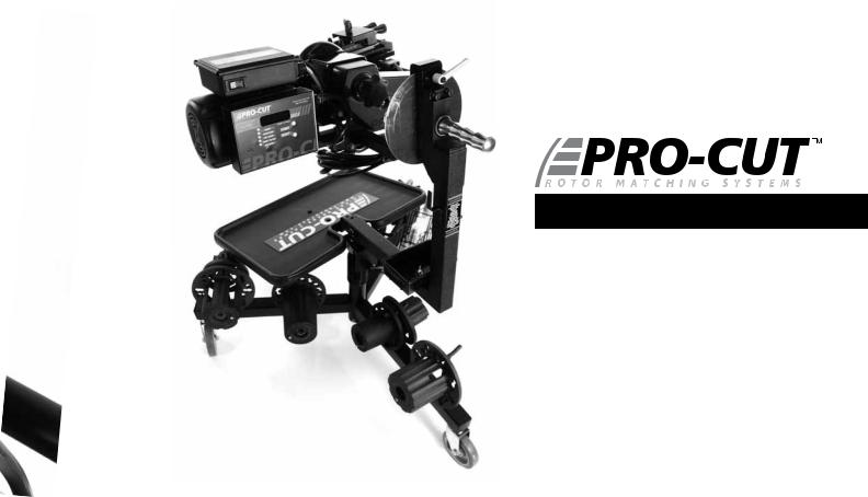
Lathe Overview |
|
|
|
|
|
|
|
5 |
|
|
4 |
|
6 |
|
|
|
|
|
|
|
|
7 |
|
|
|
|
|
|
8
2
3
14
1 
*Guard 50-1730 Not Shown
PG / Ø12 800.543.6618

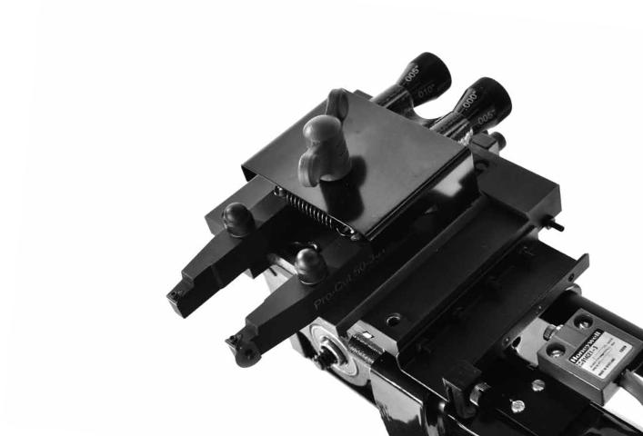
COMPONENTS
1. |
9.0 DRO Computer Box |
9. |
Automatic Shut-off Switch |
2. |
On/Off Switch |
10. |
Automatic Shut-off Cam |
3. |
120V 60 Hz or 1.5 hp 230V 50/60 Hz hp Motor |
11. |
Cut Depth Adjustment Dials |
4. |
Draw Bar Knob |
12. |
Cutting Tips/Inserts |
5. |
Adjustment Flange (obscured) |
13. |
Tool Arm Lock Lever |
6. |
Adjustment Solenoid (obscured) |
14. |
Trolley |
7. |
Feed Engagement Knob (obscured) |
NOTE* 50-1730 GUARD NOT SHOWN |
|
8.Disc-Lock Lever
WWW.PROCUTUSA.COM PG / Ø13

 SETTING UP A NEW LATHE
Before you begin setting up, check contents against the parts diagram enclosed in the lathe package. If you are missing any parts, call Pro-Cut immediately.
PG / Ø14 800.543.6618

ASSEMBLE THE TROLLEY
Open the trolley box and check contents against the parts diagram . If you are missing any parts, call Pro-Cut immediately. Proceed with assembly, following the instructions enclosed in the box.
MOUNT THE LATHE TO THE TROLLEY
Once the trolley is assembled you will need to mount the lathe to the trolley. Locate lathe arm on trolley so that lathe will be in upright horizontal position when it is installed, then lock the disc-lock lever firmly.
1 ) Remove the lathe body from the shipping pallet and install mounting studs under lathe in two threaded holes the pallet bolts were removed from.
2 ) Find another person to help lift the lathe using the handles on either end, and insert the lathe mounting studs into trolley arm. Secure with two nuts (36-001B) and flat washers (37-108).
3 ) Assemble Guard to Lathe if so equipped. See Page 48 for assembly drawing of Guard 50-1730. Guard 50-1730 is mandatory in the Province of Quebec.
Cutting 
Edge
Tip
Assemble the trolley completely then get assistance from another person to mount the lathe on the trolley.
WWW.PROCUTUSA.COM PG / Ø15

 VEHICLE PREPARATION
Before lifting the vehicle, the front wheels should be straight and the parking brake should be off, with the transmission in neutral.
1.Raise the vehicle according to the lift manufacturer’s instructions. Raise until the wheel hub is about belt level.
2.Check wheel bearings for damage or excessive play. If this or any other wheel service is required, it should be performed before match-machining the rotors as loose or damaged bearings will keep the lathe from doing the most accurate job possible.
3.Remove the wheels. Remove the brake calipers and suspend them out of the way of moving parts such as half shafts and CV joints using the yellow S-hooks provided (pn 37-034K). Be sure to remove all wheels that may turn when the lathe is turned on.
4.If the rotor is free on the hub, mark and remove it in order to assess the mating surface. Use a ScotchBrite™ type wheel on a die grinder, or other suitable wheel hub cleaning tool to remove rust or debris. Clean all material from the mounting area.
5.The rotor on the side of the wheel that is not to be machined should be marked and removed if it is free on the hub or secured with at least 2 lug nuts. Match marking the rotors to the hub is very important.
6.Use a micrometer to measure rotor thickness and determine how much material may be removed from the rotor by comparing to brake spec guide provided. Visually inspect for deep rust or grooves. This inspection will help determine the depth of the cut.
NOTE: Remember to index mark rotors before removing them so you can be sure they are returned to the same positions on the hub.
PG / Ø16 800.543.6618
 Loading...