

Page 1

OPERATOR’S MANUAL
Auto Align Bale Skoop
Models HD4SR and 12SR
K34987-04A
Page 2

Page 3

Table of Contents
Section 1:
Safety ............................................................................................................................1-1
Signal Words .................................................................................................................1-2
General Equipment Safety ............................................................................................ 1-3
General Equipment Safety Guidelines ....................................................................... 1- 3
Lighting and Marking ..................................................................................................... 1-4
Wheels and Tires ........................................................................................................... 1- 4
Tire Safety .................................................................................................................. 1- 4
Bale Skoop Operation Safety ........................................................................................1-5
Before Operating ........................................................................................................ 1- 5
During Operation ........................................................................................................ 1- 6
After Operation (Storage) ........................................................................................... 1- 7
Transport Safety .............................................................................................................1- 8
Highway and Transportation Safety ............................................................................1-8
Maintenance Safety ....................................................................................................... 1- 9
Performing Maintenance ............................................................................................1-9
Safety Signs ................................................................................................................ 1- 10
Safety Decals ........................................................................................................... 1- 10
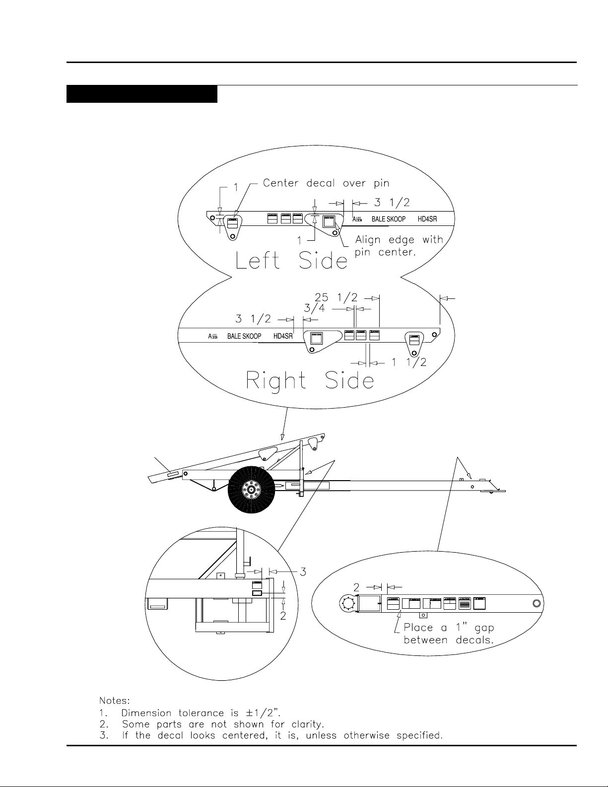
How to install a new decal ........................................................................................ 1-10
Reflector Location Guide .......................................................................................... 1-15
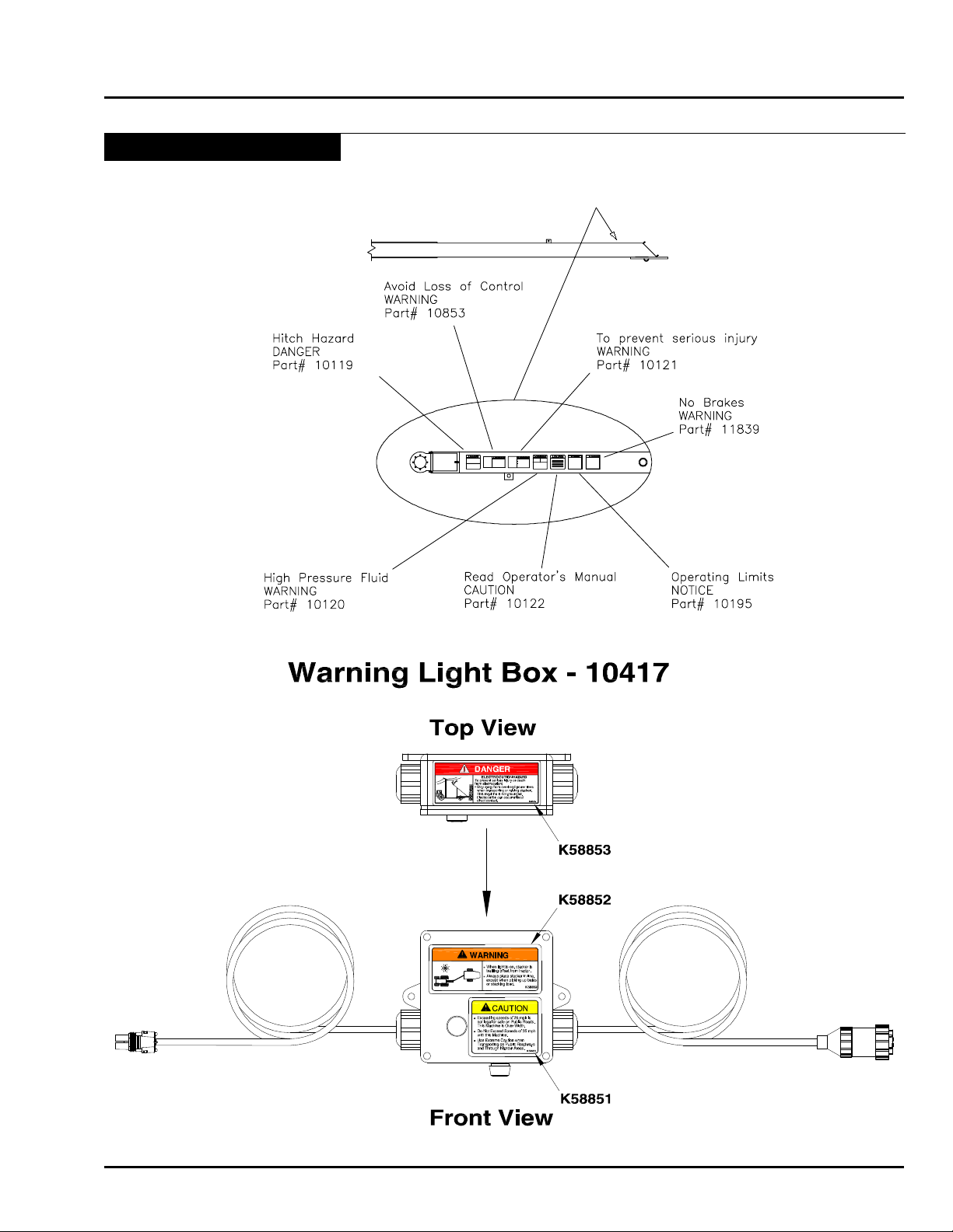
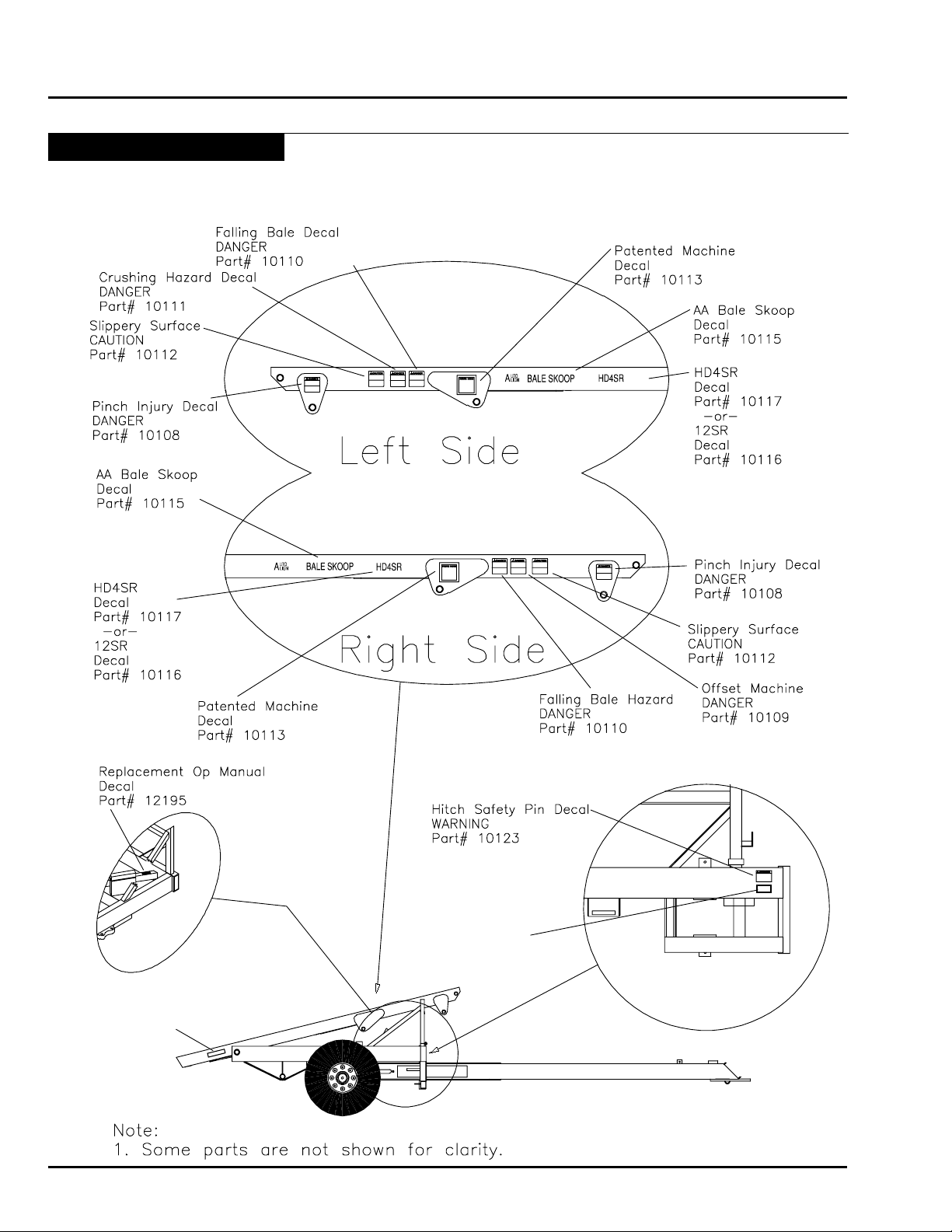
Decal Location Guide ............................................................................................... 1-1 7
Section 2:
Specifications ..............................................................................................................2-1
Machine Specifications ..................................................................................................2-2
HD4SR .......................................................................................................................2-2
12SR ..........................................................................................................................2-2
Noise Emissions ........................................................................................................2-2
Tractor Requirements .................................................................................................2-2
Tire Specifications ......................................................................................................2-2
Bale Size ....................................................................................................................2-2
Lubricants ..................................................................................................................2-2
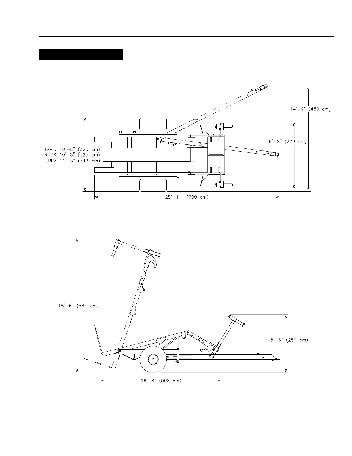
Bale Skoop Dimensions ................................................................................................2-3
Section 3:
Checklist ......................................................................................................................3-1
Manuals .........................................................................................................................3-2
Pre-Operation Checklist.................................................................................................3-3
Pre-Operation Check ..................................................................................................3-3
Section 4:
Introduction .................................................................................................................4-1
Introduction ....................................................................................................................4-2
Section 5:
Operation .....................................................................................................................5-1
Tractor ............................................................................................................................5-3
Tires ...........................................................................................................................5-3
Hydraulics ..................................................................................................................5-3
Drawbar ......................................................................................................................5-3
Machine Conventions ....................................................................................................5-4
Auto Align Bale Runner Directional Conventions .......................................................5-4
Hooking Up for the First Time ........................................................................................5-5
Parts Needed .............................................................................................................5-5
Attach Bale Skoop to Tractor .......................................................................................5-5
Connect Safety Chain ................................................................................................5-6
HD4SR & 12SR October 2015 i
Page 4

Table of Contents
Hooking Up Warning Light Assembly .........................................................................5-6
Lubricate Joints ..........................................................................................................5-6
Prime Hydraulic System .............................................................................................5-7
Pre-Operation Checklist.................................................................................................5-8
Pre-Operation Check ..................................................................................................5-8
Operation of Controls ....................................................................................................5-9
Setting up the Lever Controls .....................................................................................5-9
Hydraulic Sequencing and Lever Operation ...............................................................5-9
Building Stacks ............................................................................................................ 5-10
Starting Stacks .........................................................................................................5-10
Stacking ....................................................................................................................... 5-11
Gathering Bales........................................................................................................... 5-11
Approaching Bales ................................................................................................... 5-11
Loading Bales ..........................................................................................................5-12
If operating a 12SR model Auto Align Bale Skoop ...................................................5-12
Operating all models of Auto Align Bale Skoops ......................................................5-12
Transporting Bale Skoop ..............................................................................................5-13
Tips and Techniques ....................................................................................................5-14
Rotating Bales ..........................................................................................................5-14
Quarter Turning Bales ...............................................................................................5-14
Repositioning Bales .................................................................................................5-14
Tipping or Rolling Bales ...........................................................................................5-14
Stacking ...................................................................................................................5-15
Stacking bales of different sizes ...............................................................................5-16
Section 6:
Maintenance .................................................................................................................6-1
General ..........................................................................................................................6-2
Safety ............................................................................................................................6-2
Tighten Bolts .................................................................................................................6-3
Tires ..............................................................................................................................6-3
Preventative Maintenance .............................................................................................6-4
Hydraulic System Preventative Maintenance .................................................................6-4
Hydraulic Pressure Relief ..............................................................................................6-5
Daily Maintenance .........................................................................................................6-6
Daily Check ................................................................................................................6-6
General Maintenance ....................................................................................................6-7
General Check ...........................................................................................................6-7
To tighten Alignment Arm Chains ............................................................................6-7
Cylinder Repair ..........................................................................................................6-7
Bed Extensions ..........................................................................................................6-7
Electrical Maintenance ..................................................................................................6-8
Warning Box System ..................................................................................................6-8
Basic Maintenance and Notes ...................................................................................6-8
Wheel Bearing Adjustment ............................................................................................6-8
Wheel Bearing Adjustment Procedure (Double Nut Arrangement) .............................6-8
Electrical Diagrams .......................................................................................................6-9
Lubrication Points ........................................................................................................ 6-11
Lubricants ................................................................................................................6-11
Bolt Torque Specification Chart ................................................................................6-12
Year End Maintenance ................................................................................................6-13
Storage .....................................................................................................................6-13
Preventative Maintenance ........................................................................................6-13
ii October 2015 HD4SR & 12SR
Page 5

Table of Contents
Section 7:
Storage ......................................................................................................................... 7- 1
Preparing for Storage ....................................................................................................7- 2
Cylinder Shaft Protection .............................................................................................. 7- 3
Removing from Storage ................................................................................................. 7- 3
Section 8:
Troubleshooting...........................................................................................................8-1
Troubleshooting Guide ...................................................................................................8-2
Hydraulic System Overview ........................................................................................8-2
Troubleshooting the Hydraulics ..................................................................................8-2
Valves and Valve Functions ........................................................................................8-2
12SR Models Only .....................................................................................................8-2
Hydraulic Troubleshooting Chart ....................................................................................8-3
Loader will not raise ......................................................................................................8-3
Loader raises slow ........................................................................................................8-3
Loader lowers when alignment arms are opening .........................................................8-3
Loader lowers before alignment arm open ....................................................................8-3
Loader will not lower ......................................................................................................8-3
Loader lowers slow ........................................................................................................8-3
Alignment Arms do not center bales, or squeeze bales tight .....................................8-3
Alignment Arms open as loader raises, and close as loader lowers ...........................8-3
Grab Hooks push bale away from loader ......................................................................8-3
Grab Hooks will not engage ..........................................................................................8-3
Grab Hooks will not disengage ......................................................................................8-3
Grab Hooks engage before alignment arms ..................................................................8-3
Grab Hooks engage when loader raises, and retract when loader lowers ....................8-3
Section 9:
Parts Breakdown .........................................................................................................9-1
Bale Skoop Final Assembly ........................................................................................9-2
Loader Assembly........................................................................................................9-4
12SR - Grab Hook Assembly - 2014 to Present ..........................................................9-6
HD4SR - Short Alignment Arm Assembly...................................................................9-8
12SR - Medium Alignment Arm Assembly ..................................................................9-9
Bed Assembly ..........................................................................................................9-10
Frame Assembly .......................................................................................................9-12
Bed Rest Assembly ..................................................................................................9-14
Hitch Assembly.........................................................................................................9-16
Implement Tire and Axle Assembly - Prior to 2015 ...................................................9-18
Truck Tire and Axle Assembly - Prior to 2015 ............................................................9-20
Terra Tire and Axle Assembly - Prior to 2015 ............................................................9-22
Terra Tire and Axle Assembly - 2015 to Present ........................................................9-24
HD4SR Hydraulic Hose Schematic ..........................................................................9-26
12SR Hydraulic Hose Schematic - 2015 to Present .................................................9-28
12SR Hydraulic Hose Schematic - 2014 to 2015 ......................................................9-30
12SR Hydraulic Hose Schematic - 2004 to 2014......................................................9-32
Cylinder Specification Sheet ....................................................................................9-34
Electrical Warning Assembly ....................................................................................9-36
Electrical Assembly ..................................................................................................9-37
Index ....................................................................................................................................i
HD4SR & 12SR October 2015 iii
Page 6

Notes
Table of Contents
iv October 2015 HD4SR & 12SR
Page 7

Section 1: Safety
Safety
Section 1:
Safety 1-1
Section Contents
Signal Words ....................................................................................................................1-2
General Equipment Safety ...............................................................................................1-3
General Equipment Safety Guidelines .......................................................................1-3
Lighting and Marking ........................................................................................................1-4
Wheels and Tires ..............................................................................................................1-4
Tire Safety ..................................................................................................................1-4
Bale Skoop Operation Safety ...........................................................................................1-5
Before Operating ........................................................................................................1-5
During Operation ........................................................................................................1-6
After Operation (Storage) ...........................................................................................1-7
Transport Safety ...............................................................................................................1-8
Highway and Transportation Safety ............................................................................1-8
Maintenance Safety ..........................................................................................................1-9
Performing Maintenance ............................................................................................1-9
Safety Signs ...................................................................................................................1-10
Safety Decals ...........................................................................................................1-10
How to install a new decal ........................................................................................1-10
Reector Location Guide .........................................................................................1-15
Decal Location Guide ...............................................................................................1-17
HD4SR & 12SR June 2015 1-1
Page 8
Safety
Watch for this symbol. It identifies potential hazards
SAFETY-ALERT
SYMBOL
Familiarize yourself with the location of all decals. Read them
carefully to understand the safe operation of your machine.
Signal Words
The words DANGER, WARNING or CAUTION are used
with the safety alert symbol. Learn to recognize the
safety alerts, and follow the recommended precautions
and safe practices.
to health or personal safety. It means:
ATTENTION - BE ALERT.
YOUR SAFETY IS INVOLVED.
Three words are used in conjunction with the safety-alert symbol:
DANGER
WARNING
CAUTION
Replace any DANGER, WARNING, CAUTION or
instructional decal that is not readable or is missing. The
location and part number of these decals is identied
later in this section of the manual.
The words Important and Note are not related
to personal safety but are used to give additional
information and tips for operating or servicing this
equipment.
IMPORTANT: Identifies special instructions or
procedures which, if not strictly
observed could result in damage to, or
destruction of the machine, process or
its surroundings.
Indicates an imminently hazardous situation that, if not
avoided, will cause DEATH OR VERY SERIOUS INJURY.
Indicates a potentially hazardous situation that, if not
avoided, could cause DEATH OR SERIOUS INJURY.
Indicates a potentially hazardous situation that, if not
avoided, may cause a MINOR OR MODERATE INJURY.
NOTE: Indicates points of particular interest for more
efcient and convenient repair or operation.
1-2 June 2015 HD4SR & 12SR
Page 9

Safety
General Equipment Safety
SAFETY. . . YOU CAN LIVE WITH IT!
General Equipment Safety Guidelines
Safety of the operator is one of the main concerns in designing and developing a new piece of equipment. Designers
and manufacturers build in as many safety features as possible. However, every year many accidents occur which
could have been avoided by a few seconds of thought and a more careful approach to handling equipment. You,
the operator, can avoid many accidents by observing the following precautions presented in this manual. To avoid
personal injury, study the following precautions and insist those working with you, or for you, follow them.
Replace any CAUTION, WARNING, DANGER or instruction safety decal that is not readable or is missing. Location
of such decals is indicated in this booklet.
Do not attempt to operate this equipment under the inuence of drugs or alcohol.
Review the safety instructions with all users annually.
This equipment is dangerous to children and persons unfamiliar with its operation. The operator should be a responsible
adult familiar with farm machinery and trained in the equipment’s operations. Do not allow persons to operate or
assemble this unit until they have read this manual and have developed a thorough understanding of the
safety precautions and of how it works.
To prevent injury or death, use a tractor equipped with a Roll Over Protective System (ROPS). Do not paint over,
remove or deface any safety signs or warning decals on your equipment. Observe all safety signs and practice the
instructions on them. Never exceed the limits of a piece of machinery. If its ability to do a job, or to do so safely, is in
question - DON’T TRY IT.
HD4SR & 12SR June 2015 1-3
Page 10

Safety
Lighting and Marking
It is the responsibility of the operator to know the lighting and marking requirements of the local highway authorities
and to install and maintain any additional equipment to provide compliance with the regulations. Aftermarket lighting
kits are often available from your dealer.
This machine is equipped with lighting, marking, and signs in compliance with standards published by the American
Society of Agricultural Engineers for Slow Moving Agricultural Implements on Public Roadways.
Wheels and Tires
Tire Safety
• Failure to follow proper procedures when mounting a tire on a wheel or rim can produce an explosion which may
result in serious injury or death.
• Do not attempt to mount a tire unless you have the proper equipment and experience.
• Inating or servicing tires can be dangerous. Only trained personnel should be called to service and/or mount
tires.
• Only install tires and wheels with appropriate capacity to meet or exceed the anticipated weight to be placed on
the equipment.
DON’T FORGET! Your best assurance against accidents is a careful and responsible operator. If there is any portion
of this manual or function you do not understand, contact your local authorized dealer or the manufacturer.
1-4 June 2015 HD4SR & 12SR
Page 11

Safety
Bale Skoop Operation Safety
Before Operating
• Carefully study and understand this manual.
• Install the safety warning light to indicate when the hitch is offset.
• Do not wear loose-tting clothing which may catch in moving parts.
• Always wear protective clothing and substantial shoes.
• It is recommended that suitable protective hearing and sight protectors (eye protection) be worn.
• The operator may come in contact with certain materials which may require specic safety equipment, relative to
the handling of such materials (examples: extremely dusty molds, fungus, bulk fertilizers, etc.)
• Keep wheel lug nuts or bolts tightened to specied torque.
• Ensure that the tires are inated to the recommended pressure.
• Give the unit a visual inspection for any loose bolts, worn parts or cracked welds, and make necessary repairs.
Follow the maintenance safety instructions included in this manual.
• Be sure that there are no tools lying on or in the equipment.
• Do not use the unit until you are sure that the operating area is clear, especially of people and animals.
• Because it is possible that this equipment may be used in dry areas or in the presence of combustibles, special
precautions should be taken to prevent res and re ghting equipment should be readily available.
• Don’t hurry the learning process or take the unit for granted. Ease into it and become familiar with your new
equipment.
• Practice operation of your equipment and it’s attachment. Completely familiarize yourself and other operators with
its operation before using.
• Make sure that the brakes are evenly adjusted (if equipped with brakes).
• Use a tractor equipped with a Roll Over Protective System (ROPS) and fasten your seat belt prior to starting the
engine.
• The manufacturer does not recommend usage of a tractor with ROPS removed.
• Move tractor wheels to the widest recommended settings to increase stability.
• Securely attach to towing unit. Use the plates, bolts and nuts provided with the machine.
• Do not allow anyone to stand between the hitch and the towing vehicle when backing up to the equipment.
HD4SR & 12SR June 2015 1-5
Page 12

Safety
Bale Skoop Operation Safety - Continued
During Operation
• SAFETY CHAIN: If the Bale Skoop is going to be transported on a public highway, the safety chain should be
connected. Always follow state and local regulations regarding a safety chain and auxiliary lighting when towing
farm equipment on a public highway. Only a safety chain (not an elastic or nylon/plastic tow strap) should be
used to retain the connection between the towing and towed machines in the event of separation of the primary
attaching system.
• Install the safety chain by crossing the chains under the hitch and secure to the draw bar cage, hitch or bumper
frame.
• Beware of bystanders, particularly children! Always look around to make sure that it is safe to start the engine
of the towing vehicle or move the unit. This is particularly important with high noise levels and quiet cabs, as you
may not hear people shouting.
• NO PASSENGERS ALLOWED: Do not carry passengers anywhere on or in the tractor or equipment.
• The tops of the bed and loader are extremely slippery, do not climb, stand, or crawl on them.
• Keep bystanders at least twenty-ve feet away from an operating machine or stacked hay. This allows bystanders
time to get away from a falling stack or away from a moving machine. The operator is a very busy person and it
is easy to miss seeing an observer while operating the Bale Skoop.
• Keep hands and clothing clear of moving parts.
• Do not clean, lubricate or adjust your equipment while it is moving.
• When halting operation, even periodically, set the tractor’s or towing vehicle’s brakes, disengage the PTO, shut
off the engine and remove ignition key.
• Be especially observant of the operating area and terrain - watch for holes, rocks or other hidden hazard. Always
inspect the area prior to operation.
• DO NOT operate near the edge of drop-offs or banks.
• DO NOT operate on steep slopes as overturn may result.
• Operate up and down (not across) intermediate slopes. Avoid sudden starts and stops.
• Pick the attest possible route when transporting across elds. Avoid the edges of ditches or gullies and steep
hillsides.
• Always return the hitch to the in-line position whenever moving from the stack to the bales or the bales to the
stack.
• Be extra careful when working on inclines.
• Periodically clear the equipment of brush, twigs or other materials to prevent buildup of dry combustible materials.
• Maneuver the tractor or towing vehicle at safe speeds.
• Avoid overhead wires or other obstacles. Contact with overhead lines could cause serious injury or death.
• Avoid loose ll, rocks and holes; they can be dangerous for equipment operation or movement.
• Allow for unit length when making turns.
• Do not walk or work under raised components or attachments unless securely positioned and blocked.
• Keep all bystanders, pets and livestock clear of the work area.
1-6 June 2015 HD4SR & 12SR
Page 13

Safety
Bale Skoop Operation Safety - Continued
During Operation - Continued
• Operate the towing vehicle from the operator’s seat only.
• Never stand alongside of unit with engine running or attempt to start engine and/or operate machine while standing
alongside of unit.
• Never leave running equipment attachments unattended.
• As a precaution, always recheck the hardware on equipment following every 100 hours of operation. Correct all
problems. Follow the maintenance safety procedures.
After Operation (Storage)
• Following operation, or when unhitching, stop the tractor or towing vehicle, set the brakes, disengage the PTO
and all power drives, shut off the engine and remove the ignition key.
• Store the unit in an area away from human activity.
• Do not park equipment where it will be exposed to livestock for long periods of time. Equipment damage and
livestock injury could result.
• The tops of the bed and loader are extremely slippery, do not climb, stand, or crawl on them.
• Do not permit children to play on or around the stored unit.
• Make sure all parked machines are on a hard, level surface and engage all safety devices.
• Wheel chocks may be needed to prevent unit from rolling.
HD4SR & 12SR June 2015 1-7
Page 14

Safety
Transport Safety
Highway and Transportation Safety
CAUTION: Exceeding speeds of 20 mph (32 km/h) is not legal or safe on public roads.
DO NOT exceed 20 mph (32 km/h) with this machine.
WARNING: This machine is over width. Use extreme caution transporting on Public
Roadways and through narrow areas.
WARNING: Use Hitch Safety Pin to lock hitch in the in-line position before transporting
Bale Skoop on public roads. This will secure hitch in case of accidental activation or
failure of hitch cylinder.
• Adopt safe driving practices. . .
• Keep the brake pedals latched together at all times. NEVER USE INDEPENDENT BRAKING WITH MACHINE
IN TOW AS LOSS OF CONTROL AND/OR UPSET OF UNIT CAN RESULT.
• Always drive at a safe speed relative to local conditions and ensure that your speed is low enough for an emergency
stop to be safe and secure.
• Reduce speed prior to turns to avoid the risk of overturning.
• Avoid sudden uphill turns on steep slopes.
• Always keep the tractor or towing vehicle in gear to provide engine braking when going downhill. Do not coast.
• Do not drink and drive!
• Comply local laws governing highway safety and movement of farm machinery on public roads.
• Be sure stock lights as well as accessory lights are connected and operating properly.
• Use approved accessory lighting, ags and necessary warning devices to protect operators of other vehicles on
the highway during daylight and night time transport. Various safety lights and devices are available from your
dealer.
• The use of ashing amber lights is acceptable in most localities, however some localities prohibit their use. Local
laws should be checked for all highway lighting and marking requirements.
• When driving the tractor and equipment on the road or highway under 20 mph (32 km/h) at night or during the
day, use ashing amber warning lights and a slow moving vehicle (SMV) identication emblem.
• Plan your route to avoid heavy trafc.
• Be a safe courteous driver. Always yield to oncoming trafc in all situations, including narrow bridges, intersections,
etc.
• Watch for obstructions overhead and to the side while transporting.
• Always operate equipment in a position to provide maximum visibility at all times. Make allowances for increased
length, width and weight of the equipment when making turns, stopping the unit, etc.
1-8 June 2015 HD4SR & 12SR
Page 15

Safety
Maintenance Safety
Performing Maintenance
• Good maintenance is your responsibility. Poor maintenance is an invitation for trouble.
• Make sure there is plenty of ventilation. Never operate the engine of the towing vehicle in a closed building. The
exhaust fumes may cause asphyxiation.
• Before working on this machine, stop the towing vehicle, set the brakes, disengage the PTO and all power drives,
shut off the engine and remove the ignition key.
• Be sure the bed is lowered against the bed rest and the loader is resting on the hitch or in its lowered position.
• Be certain all moving parts on attachments have come to a complete stop before attempting to perform maintenance.
• Always use a safety support and block the wheels. Never use a jack to support the machine.
• Always use the proper tools or equipment for the job at hand. Use extreme caution when making adjustments.
• A torque chart is provided in this manual for reference when tightening bolts and nuts.
• Never use your hands to locate a hydraulic leak on attachments. Use a piece of cardboard or wood. Hydraulic
uid escaping under pressure can penetrate the skin.
• When disconnecting hydraulic lines, shut off hydraulic supply and relieve all hydraulic pressure (see maintenance
section for instructions).
• Openings in the skin and minor cuts are susceptible to infection from hydraulic uid. If injured by escaping hydraulic
uid, see a doctor at once. Without immediate medical treatment, serious infection, gangrene and allergic reactions
can occur.
• Replace all shields and guards after servicing and before moving.
• After servicing, be sure all tools, parts and service equipment are removed.
• Do not allow grease or oil to build up on any step or platform.
• Never replace hex bolts with less than grade eight bolts unless otherwise specied. Refer to bolt torque chart for
head identication marking.
• Where replacement parts are necessary for periodic maintenance and servicing, genuine factory replacement parts
must be used to restore your equipment to original specications. The manufacturer will not claim responsibility
for use of unapproved parts and/or accessories and other damages as a result of their use.
• If equipment has been altered in any way from original design, the manufacturer does not accept any liability for
injury or warranty.
• A re extinguisher and rst aid kit should be kept readily accessible while performing maintenance on this equipment.
HD4SR & 12SR June 2015 1-9
Page 16
Safety
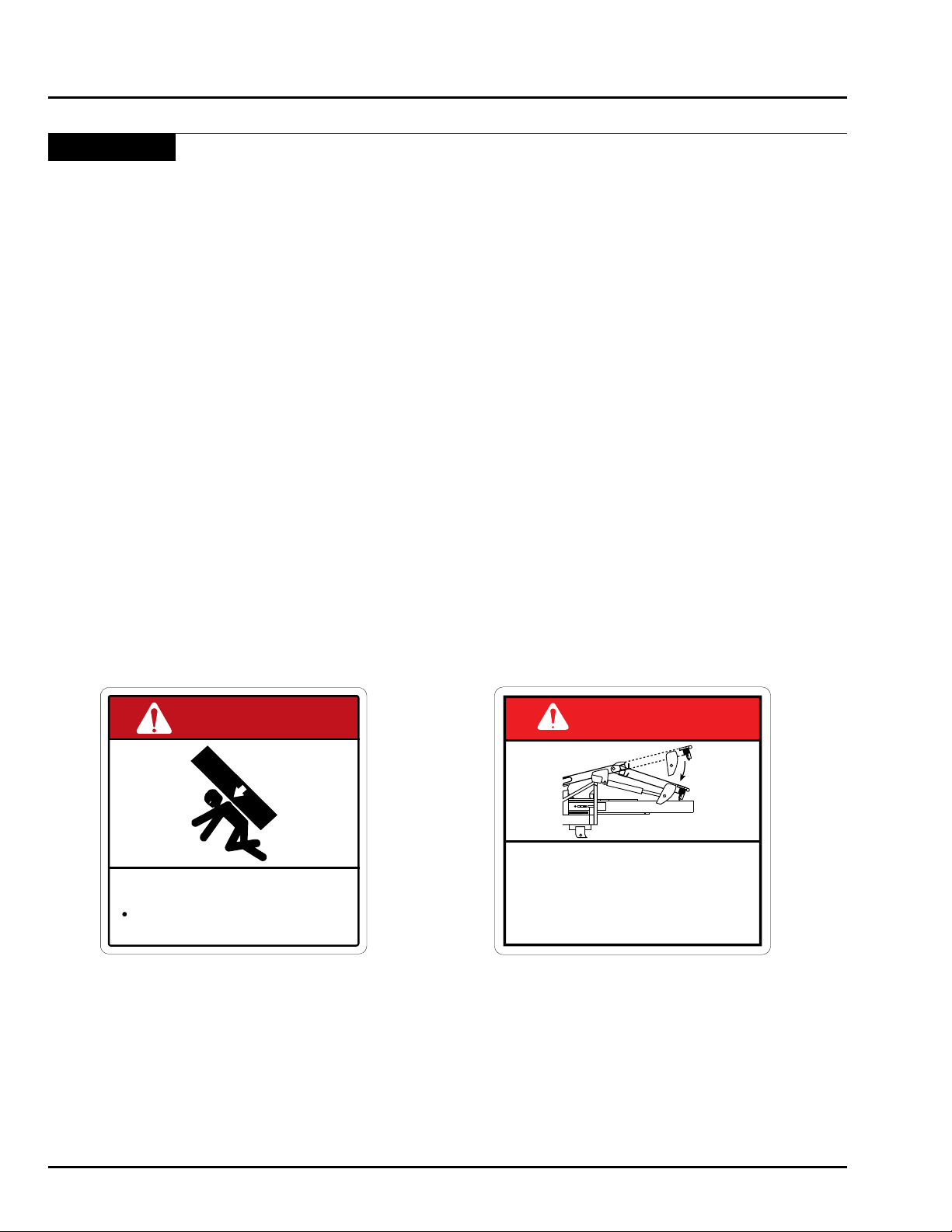
DANGER
CRUSHING HAZARD
• Always rest loader on hitch
and turn off tractor before
working on loader.
10111
Safety Signs
Safety Decals
• Keep safety decals and signs clean and legible at all times.
• Replace safety decals and signs that are missing or have become illegible.
• Parts that have been replaced that once displayed a safety sign should have the sign replaced as well.
• Safety decals or signs are available from your distributor, dealer parts department, or the manufacturer.
How to install a new decal
1. Be sure that the installation area is clean and dry.
2. Decide on the exact position before you remove the backing paper.
3. Remove the smallest portion of the split backing paper.
4. Align the decal over the specied area and carefully press the small portion with the exposed sticky backing in
place.
5. Slowly peel back the remaining paper and carefully smooth the remaining portion of the decal in place.
6. Small air pockets can be pierced with a pin and smoothed out using the decal backing paper.
To determine missing decals, or to locate proper locations of replacements refer
to the “Decal Location Guide” later in this section.
DANGER
To prevent serious injury or death
from crushing:
Stand clear of machine and stack to
avoid being struck by falling bale.
Part # 10110 – Danger Falling Bale Hazard
10110
Part # 10111 Danger Crushing Hazard
Location: Both sides of bed.
Location: Left side of bed.
1-10 June 2015 HD4SR & 12SR
Page 17
Safety Signs - Continued
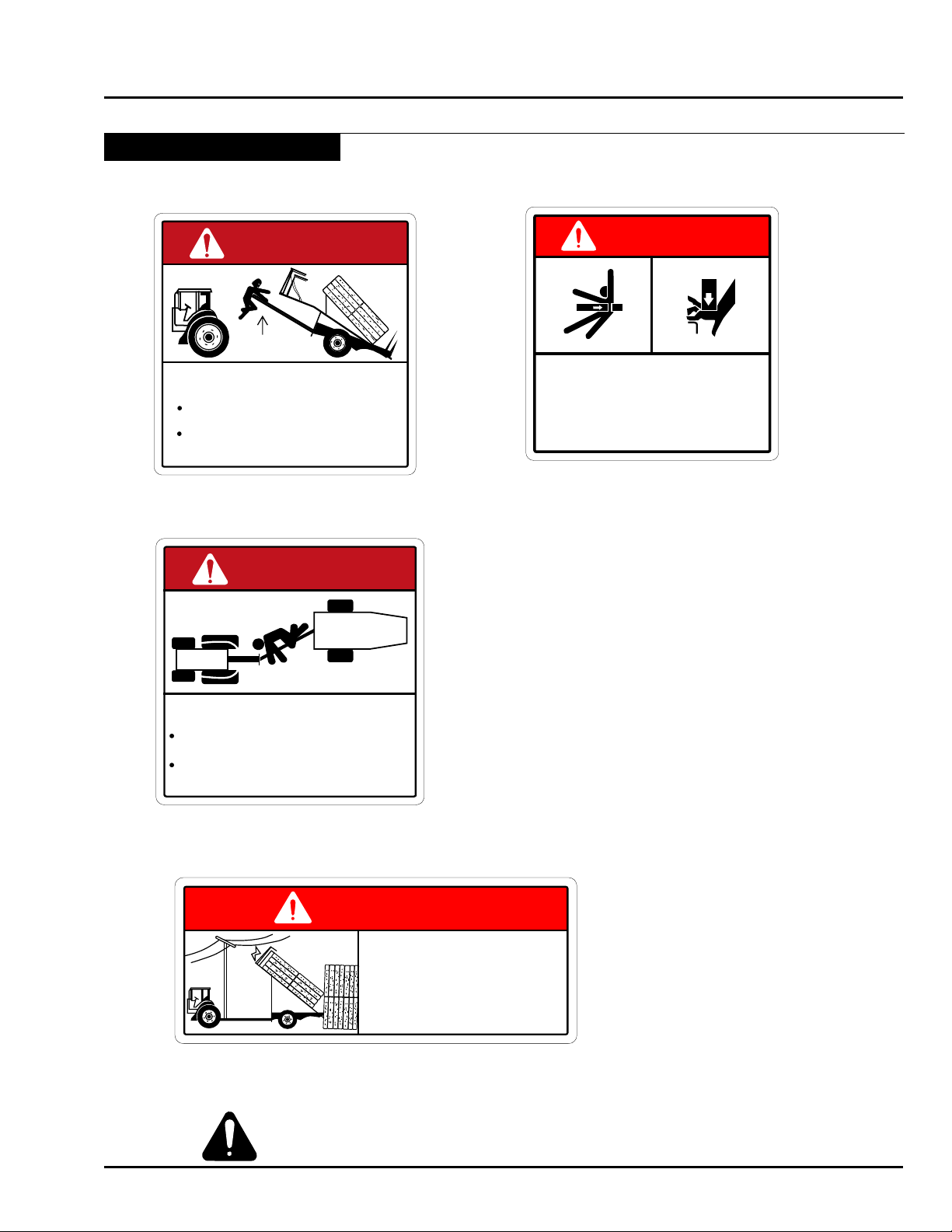
DANGER
K eep people c lea r o f mac hine
while in motio n.
Warn p eople not to app ro ac h fro m
the R IG HT s ide.
OF F S E T M AC HINE
10109
DANGER
10108
To prevent serious injury or death
from pinching:
• Keep all persons and objects clear
while any part of this machine is in
motion.
DANGER
ELECTROCUTION HAZARD
To prevent serious injury or death from
electrocution:
• Stay away from overhead power lines
when transporting or raising stacker.
This machine is not grounded.
Electrocution can occur without direct
contact.
10106
DANGER
HIT C H HAZ AR D
To avo id injury :
U nload all bales b efor e d is conne cti ng
fro m tr ac tor.
M ove bed a nd loa der to low es t pos ition
be fore dis conne cting hydra ulic ho se s
and hitc h.
Part # 10119 – Danger Hitch Hazard
Location: Top of hitch.
Safety
10119
Part # 10108 - Danger Pinch Injury
Location: Both sides of bed.
Part # 10109 - Danger Offset Machine
Location: Right side of bed.
Part # 10106 - Danger Electrocution Hazard
Location: On warning light box.
HD4SR & 12SR June 2015 1-11
Familiarize yourself with the location of all decals. Read them
carefully to understand the safe operation of your machine.
Page 18
Safety
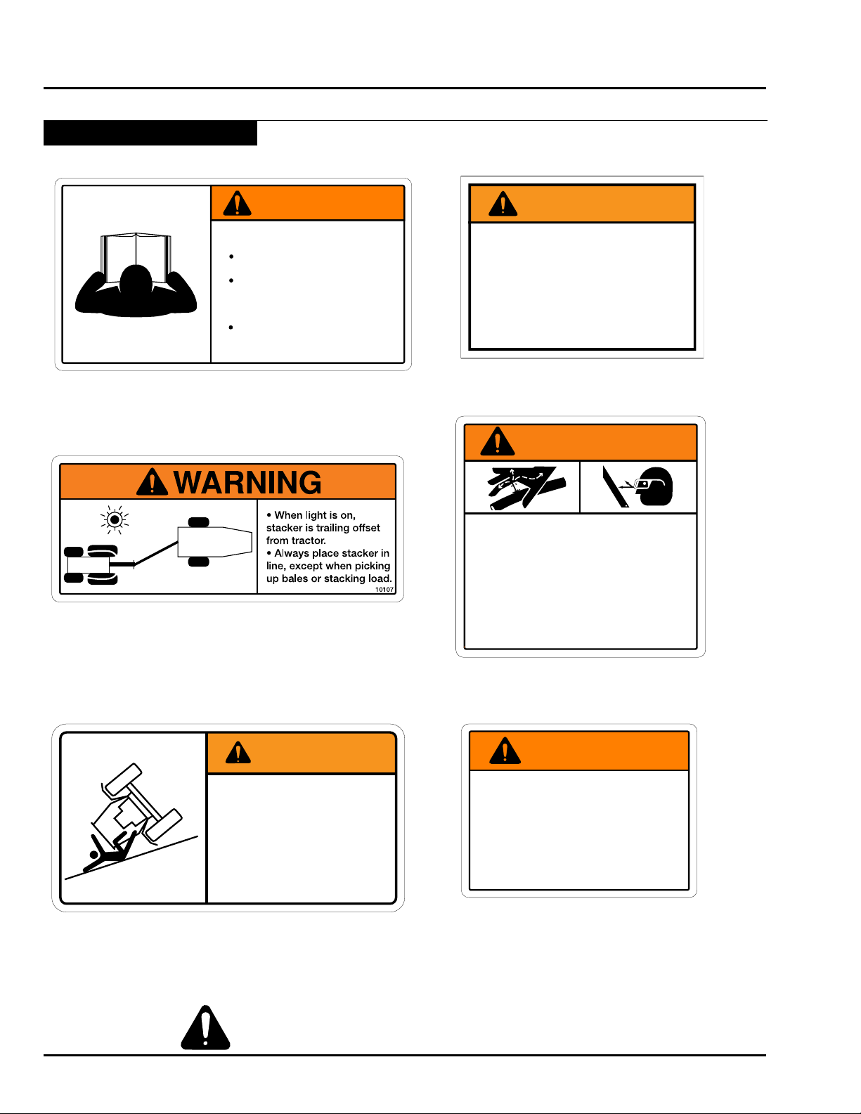
WARNING
Avoid possible loss of control or
tractor overturn.
Tow only with correctly ballasted
tractor weighing:
12SR - no less than 14 000 lbs
(6350 kg)
HD4SR - no less than 10 750 lbs
(4880 kg)
10853
WARNING
HITCH SAFETY PIN
• Always secure hitch by
installing safety pin before
driving down the road,
highway or street.
10123
WARNING
HIGH-PRESSURE FLUID HAZARD
To prevent serious injury or death:
• Relieve pressure on system before
repairing or adjusting or disconnecting.
• Wear proper hand and eye protection
when searching for leaks. Use wood or
cardboard instead of hands.
• Keep all components in good repair.
10120
WARNING
To Prevent Serious Injury or Death
Avoid unsafe operation or
maintenance.
Do not operate or work on this
machine without reading and
understanding the operator’s
manual.
If manual is lost, contact your
nearest dealer for a new manual.
10121
This machine may require a long distance
to stop because of NO BRAKES.
To Prevent Accidents
11839
WARNING
• Do not pull over 20 mph (32 km/h)
• Avoid steep inclines
• Minimum Tractor Horsepower Required:
• HD4SR - 125 HP (93 kW)
• 12SR - 125 HP (93kW)
• 12K - 150 HP (112kW)
• 16K - 180 HP (134 kW)
Safety Signs - Continued
Part # 10121 – Warning To Prevent Serious Injury
Location: Top of hitch.
Part # 11839 - Warning No Brakes
Location: Top of hitch.
Part # 10107 - Warning Offset Machine
Location: On warning light box.
Part # 10120 - Warning High Pressure Fluid
Location: Top of hitch.
Part # 10853 - Warning Avoid Loss of Control
Location: Top of hitch.
1-12 June 2015 HD4SR & 12SR
Familiarize yourself with the location of all decals. Read them
carefully to understand the safe operation of your machine.
Part # 10123 - Warning Hitch Safety Pin
Location: Front of frame above hitch.
Page 19
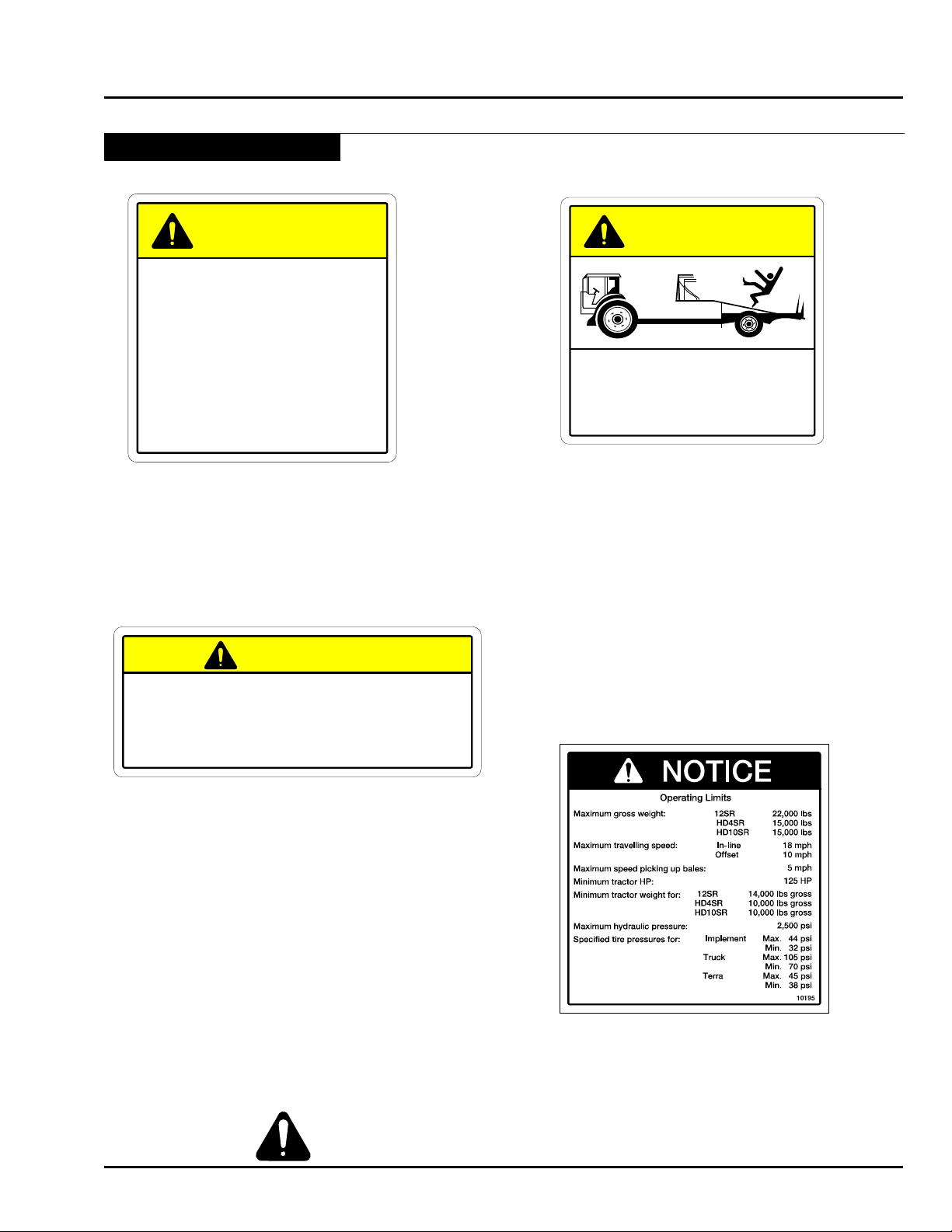
Safety Signs - Continued
CAUTION
• Exceeding speeds of 25 mph is not legal or safe on Public Roads.
This Machine is Over Width.
• Do Not Exceed Speeds of 25 mph with this Machine.
• Use Extreme Caution when Transporting on Public Roadways and
Through Narrow Areas.
This machine is equipped with lighting, markings, and signs in compliance with
standards published by the American Society of Agricultural Engineers for Slow
Moving Agricultural Implements on Public Roadways.
11159
CAUTION
10112
SLIPPERY SURFACE
To avoid injury:
• Do not stand or walk on machine.
CAUTION
1. Read Operator's Manual before using machine.
2. Stop tractor engine, lower machine to the ground, place all
controls in neutral, set park brake, remove ignition key and
wait for all moving parts to stop before servicing, adjusting,
repairing, unplugging or fitting.
3. Keep hands, feet, hair and clothing away from moving parts.
4. Do not allow riders.
5. Keep all hydraulic lines, fittings and couplers tight and free
of leaks before using.
6. Install safety locks before transporting or working beneath
components.
7.
Add extra lights and use pilot vehicle when transporting during
times of limited visibility.
8. Use hazard flashers in tractor when transporting.
9. Install safety chain when attaching to tractor.
10. Keep away from overhead electrical lines. Electrocution can
occur without direct contact.
11. Review safety instructions with all operators annually.
FN-D-10122
Part # 10122 – Caution Read Op Manual
Location: Top of hitch.
Safety
Part # 10112 - Caution Slippery Surface
Location: Both sides of bed.
Part # 11159 - Caution Speed
Location: On warning light box.
HD4SR & 12SR June 2015 1-13
Familiarize yourself with the location of all decals. Read them
carefully to understand the safe operation of your machine.
Part # 10195 - Notice
Location: Left side of hitch.
Page 20
Safety
For Replacement
Operator's Manuals
Call: 306-933-8585
Or write to:
MORRIS Industries (USA) Inc.
Box 1117
Minot, ND 58702-1117
12195
PATENTED MACHINE
Copying this machine is
illegal and any company or
corporation found to have a
copy or copies of this
machine will be infringing on
U.S. Patent No. 5,211,345;
Issue date 5/18/93 and
U.S. Patent No. 5,397,208;
Issue date 3/14/95 and will be
penalized for said act
according to U.S. patent law.
10113
12194
Safety Signs - Continued
Part # 12194 - ProAG Logo Decal
Location: Rear sides of bed.
Part # 12195 - Replacement Manual
Location: On frame by op manual box
Part # 10116 - 12SR
Location: Both sides of bed.
Part # 10117 - HD4SR
Location: Both sides of bed.
Part # 10115 - Auto Align Bale Skoop
Location: Both sides of bed.
1-14 June 2015 HD4SR & 12SR
Part # 10113 - Patented Machine
Location: Both sides of bed.
Familiarize yourself with the location of all decals. Read them
carefully to understand the safe operation of your machine.
Page 21
Safety Signs - Continued
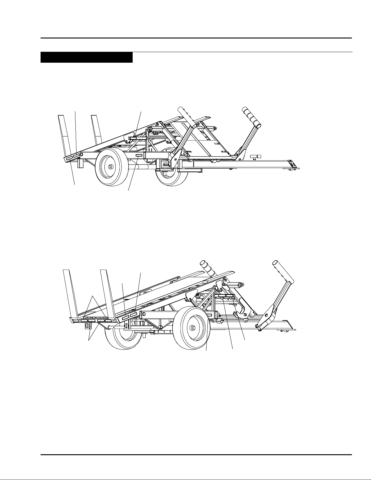
Reector Location Guide
Safety
12194
N34477
N34477
N34477
N34476 - RED REFLECTOR TAPE 2x 9
N34477 - YELLOW REFLECTOR TAPE 2 x 9
N34478 - ORANGE REFLECTOR TAPE 2x 9
12194 - PROAG DECAL
12194
N34477
N34476
N34478
N34477
HD4SR & 12SR June 2015 1-15
N34477
N34478
Page 22
Safety
Safety Signs - Continued
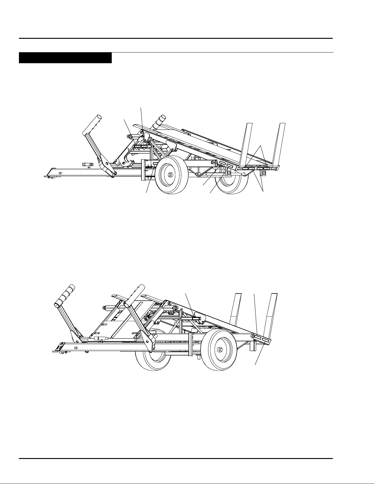
Reector Location Guide - Continued
N34478
N34476
N34477
12194
N34477
N34476
N34478
N34476 - RED REFLECTOR TAPE 2x 9
N34477 - YELLOW REFLECTOR TAPE 2 x 9
N34478 - ORANGE REFLECTOR TAPE 2x 9
12194 - PROAG DECAL
N34477
12194
N34477
1-16 June 2015 HD4SR & 12SR
Page 23
Safety Signs - Continued
Decal Location Guide
Safety
HD4SR & 12SR June 2015 1-17
Page 24
Safety
PROAG
Decal
Part # 12194
Serial # Plate
Safety Signs - Continued
Decal Location Guide - Continued
1-18 June 2015 HD4SR & 12SR
Page 25
Safety Signs - Continued
PROAG
Decal
Part # 12194
Decal Location Guide - Continued
Safety
HD4SR & 12SR June 2015 1-19
Page 26

Safety
Notes
1-20 June 2015 HD4SR & 12SR
Page 27

Section 2:
Specications
Specications
Section 2:
Specications 2-1
Section Contents
Machine Specications .....................................................................................................2-2
HD4SR .......................................................................................................................2-2
12SR ..........................................................................................................................2-2
Noise Emissions ........................................................................................................2-2
Tractor Requirements .................................................................................................2-2
Tire Specications ......................................................................................................2-2
Bale Size ....................................................................................................................2-2
Lubricants ..................................................................................................................2-2
Bale Skoop Dimensions ...................................................................................................2-3
HD4SR & 12SR June 2015 2-1
Page 28

Specications
Machine Specications
HD4SR
Maximum lift capacity of the loader ......................................................................... 3,000 lbs (1361 kg)
Maximum Gross Vehicle Weight ............................................................................ 15,000 lbs (6800 kg)
Road-siding capacity in tons/hour ..........................................................................30-50 (27 t/h-45 t/h)
Tires ...................................................................................... Implement, Dual Truck or High Floatation
Stacker weight ......................................................................................................... 6,600 lbs (2990 kg)
Tongue weight empty .................................................................................................... 800 lbs (363 kg)
Tongue weight loaded ................................................................................................ 1,300 lbs (590 kg)
Tongue weight stacking...........................................................................................-4,000 lbs (-1814 kg)
12SR
Maximum lift capacity of the loader .......................................................................... 3,000 lbs (1361 kg)
Maximum Gross Vehicle Weight ............................................................................ 22,000 lbs (9980 kg)
Road-siding capacity in tons/hour ...........................................................................30-50 (27 t/h-45 t/h)
Tires ........................................................................................................... Dual Truck or High Floatation
Stacker weight ...........................................................................................................7,500 lbs (3400 kg)
Tongue weight empty ..................................................................................................... 800 lbs (363 kg)
Tongue weight loaded 1,300 lbs (590 kg)
Tongue weight stacking.......................................................................................... -6,700 lbs (-3039 kg)
Noise Emissions
(With reference to ISO 11204 and EN 1553 - Annex D)
Continuous A-weighted sound pressure (L
Peak C-weighted sound pressure (L
Cpk
Tractor Requirements
HP requirements ..............................................................................................125HP (93 kW) minimum
Tractor weight - HD4SR (min) .................................................................................10,750 lbs (4880 kg)
Tractor weight - 12SR (min)..................................................................................... 14,000 lbs (6350 kg)
Hydraulic pressure ..................................................................................................2,200 psi (15.2 MPa)
Hydraulic flow ............................................................................................................. 20 Gpm (1.26 L/s)
Hydraulic controls .....................................................................3 remotes (2 with double selector valve)
) ............................................................................ 83.7 dB
Aeq
) ..................................................................................... 112.6 dB
Tire Specifications
Implement tire size .......................................................................................................21.5 x 16.1 14ply
Maximum implement tire pressure .................................................................................44 psi (303 kPa)
Minimum implement tire pressure ..................................................................................32 psi (221 kPa)
Recommended implement tire pressure ........................................................................ 40 psi (276 kPa)
Truck tire size ............................................................................................................................ 11R-24.5
Maximum truck tire pressure .......................................................................................105 psi (724 kPa)
Minimum truck tire pressure ..........................................................................................70 psi (483 kPa)
Recommended truck tire pressure .................................................................................75 psi (517 kPa)
High flotation tire size ................................. Alliance 600/55-22.5 or TVS Eurogrip 600/50-22.5 - 16-Ply
Maximum flotation tire pressure .....................................................................................45 psi (310 kPa)
Minimum flotation tire pressure ......................................................................................38 psi (262 kPa)
Recommended flotation tire pressure ............................................................................40 psi (276 kPa)
Bale Size
Minimum Bale Length ....................................................................................................6 1/2 ft (198 cm)
Maximum Bale Length ...................................................................................................8 1/2 ft (259 cm)
Lubricants
Hydraulic oil .................................................... High quality that meets or exceeds tractor specifications
Axle hub oil .................................................................................................................... 80-90 gear lube
Grease ............................................................................................................................ Non clay based
Bale slide surface .......................................................................Dry film graphite lubricant (Slip-Plate®)
2-2 June 2015 HD4SR & 12SR
Page 29
Bale Skoop Dimensions
Specications
HD4SR & 12SR June 2015 2-3
Page 30

Specications
Notes
2-4 June 2015 HD4SR & 12SR
Page 31

Section 3: Checklist
Checklist
Section 3:
Checklist 3-1
Section Contents
Manuals ............................................................................................................................3-2
Pre-Operation Checklist ...................................................................................................3-3
Pre-Operation Check .................................................................................................3-3
HD4SR & 12SR June 2015 3-1
Page 32

Checklist
SAFETY-ALERT
SYMBOL
Watch for this symbol. It identies
potential hazards to health or personal
safety. It points out safety precautions.
It means:
ATTENTION - BE ALERT.
Your safety is involved.
Manuals
Note: Pre-Delivery Inspection Form must be
completed and submitted to Morris Industries
within 30 days of delivery date.
Warranty Void if Not Registered
3-2 June 2015 HD4SR & 12SR
Page 33

ECNEREFERRENWO
:ledoM
:oNlaireS
:relaeD
:nwoT:etatS
:enohP
:ROTAREPO/RENWO
:etaD
Pre-Operation Checklist
Checklist
Please read the Operator’s Manual carefully
and become a “SAFE” operator.
Adopt a good lubrication and maintenance
program.
Before operating Bale Skoop check the
following items:
Pre-Operation Check
Lug nuts - Check that all lug nuts are present
and torqued to the appropriate specification.
Pin retaining bolts - Check for any missing or
loose bolts or pins, replace or tighten as necessary.
Hydraulic hoses - Inspect all hydraulic hoses and
replace any worn hoses. Remember: Use a piece
of cardboard or wood and look for leaks, replace
leaky hoses.
Jack - Check that jack has been moved to the
upper jack stud on TOP of the hitch.
Hitch Safety Pin - If traveling, check that the Hitch
Safety Pin is securely in place. If gathering or
stacking, check that the Hitch Safety Pin has been
removed.
Warning Light - Check that the Warning Light
functions properly.
Lighting - Make sure the lighting is hooked up and
functioning properly.
Tire Pressure - Check tire pressure to make sure
it is within the specified range given on page 2-2
in the Machine Specifications section.
Hitch Connection - Check the bolt system that
connects the stacker to the tractor drawbar. A loose
connection will wear faster and possibly uncouple.
TAKE SAFETY SERIOUSLY.
DO NOT TAKE
NEEDLESS CHANCES!!
HD4SR & 12SR June 2015 3-3
Page 34

Checklist
Notes
3-4 June 2015 HD4SR & 12SR
Page 35

Section 4: Introduction
Introduction
Section 4:
Introduction 4-1
Section Contents
Introduction .......................................................................................................................4-2
HD4SR & 12SR June 2015 4-1
Page 36
Introduction
Introduction
This Operator’s Manual has been carefully prepared to
provide the necessary information regarding operation
and adjustments, so that you may obtain maximum
service and satisfaction from your new ProAG Auto
Align Bale Skoop.
To protect your investment, study your manual before
starting or operating in the eld. Learn how to operate
and service your Auto Align Bale Skoop correctly, failure
to do so could result in personal injury or equipment
damage.
If you should find that you require information not
covered in this manual, contact your local ProAG Dealer.
The Dealer will be glad to answer any questions that
may arise regarding the operation of your ProAG Auto
Align Bale Skoop.
ProAG Dealers are kept informed on the best methods of
servicing and are equipped to provide prompt, efcient
service if needed.
Occasionally, your Auto Align Bale Skoop may require
replacement parts. Your Dealer will be able to supply
you with the necessary replacement parts required. If
the Dealer does not have the necessary part, the ProAG
Factory will promptly supply the Dealer with it.
Your ProAG Auto Align Bale Skoop is designed to give
satisfaction even under difcult conditions. A small
amount of time and effort spent in protecting it against
rust, wear and replacing worn parts will increase the
life and trade-in value.
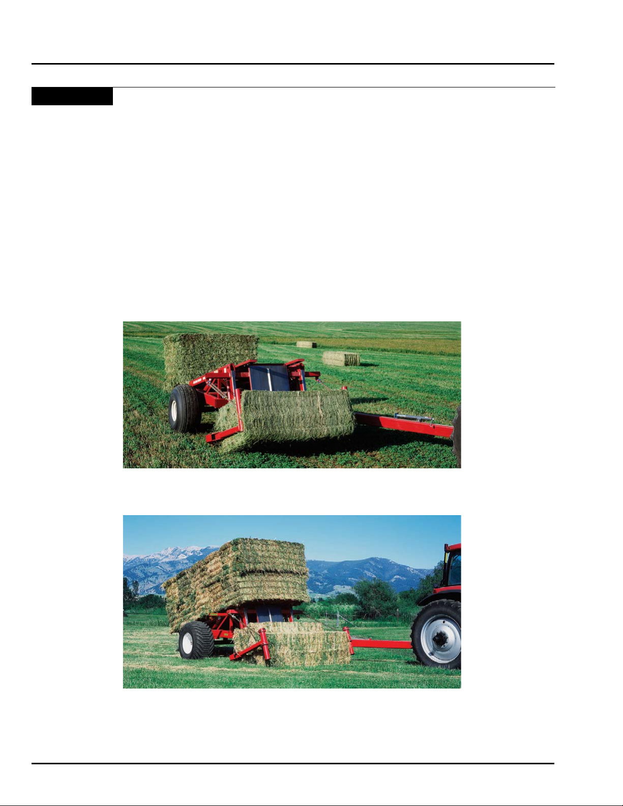
Shown: HD4SR
Shown: 12SR
Keep this book handy for ready reference at all times. It is the policy of ProAG to improve its products whenever
it is possible to do so. The Company reserves the right to make changes or add improvements at any time without
incurring any obligation to make such changes on machines sold previously.
4-2 June 2015 HD4SR & 12SR
Page 37

Section 5: Operation
Operation
Section 5:
Operation 5-1
Section Contents
Tractor ...............................................................................................................................5-3
Tires ...........................................................................................................................5-3
Hydraulics ..................................................................................................................5-3
Drawbar ......................................................................................................................5-3
Machine Conventions .......................................................................................................5-4
Auto Align Bale Runner Directional Conventions .......................................................5-4
Hooking Up for the First Time ...........................................................................................5-5
Parts Needed .............................................................................................................5-5
Attach Bale Skoop to Tractor ......................................................................................5-5
Connect Safety Chain ................................................................................................5-6
Hooking Up Warning Light Assembly .........................................................................5-6
Lubricate Joints ..........................................................................................................5-6
Prime Hydraulic System .............................................................................................5-7
Pre-Operation Checklist ...................................................................................................5-8
Pre-Operation Check .................................................................................................5-8
Operation of Controls .......................................................................................................5-9
Setting up the Lever Controls .....................................................................................5-9
Hydraulic Sequencing and Lever Operation ...............................................................5-9
Building Stacks ...............................................................................................................5-10
Starting Stacks .........................................................................................................5-10
Stacking ..........................................................................................................................5-11
Gathering Bales ..............................................................................................................5-11
Approaching Bales ...................................................................................................5-11
Loading Bales ..........................................................................................................5-12
If operating a 12SR model Auto Align Bale Skoop ...................................................5-12
Operating all models of Auto Align Bale Skoops ......................................................5-12
Transporting Bale Skoop ................................................................................................5-13
Tips and Techniques ....................................................................................................... 5-14
Rotating Bales ..........................................................................................................5-14
HD4SR & 12SR June 2015 5-1
Page 38

Operation
Section Contents
Quarter Turning Bales ..............................................................................................5-14
Repositioning Bales .................................................................................................5-14
Tipping or Rolling Bales ...........................................................................................5-14
Stacking ...................................................................................................................5-15
Stacking bales of different sizes ...............................................................................5-16
5-2 June 2015 HD4SR & 12SR
Page 39
CAUTION
BE ALERT
Operation
SAFETY FIRST
REFER TO SECTION 1 AND REVIEW
ALL SAFETY RECOMMENDATIONS.
Tractor
Tires
• Proper ballast and tire pressure are required when
pulling heavy implements.
• Consult your tractor operator’s manual and follow all
recommended procedures.
Hydraulics
• Wipe all hydraulic ttings and couplers with a clean
cloth to avoid contaminating the system.
• Check that the hydraulic reservoir is lled to the
proper level.
Drawbar
• Center and pin in a xed position for easier hitching
and greater stability.
Warning
Do not permit smoking, sparks or an open
ame where combustible fuels are being used.
Keep the work area well ventilated.
Warning
Do not search for high-pressure hydraulic
leaks without hand and face protection. A
tiny, almost invisible leak can penetrate
skin, thereby requiring immediate medical
attention.
HD4SR & 12SR June 2015 5-3
Page 40
Operation
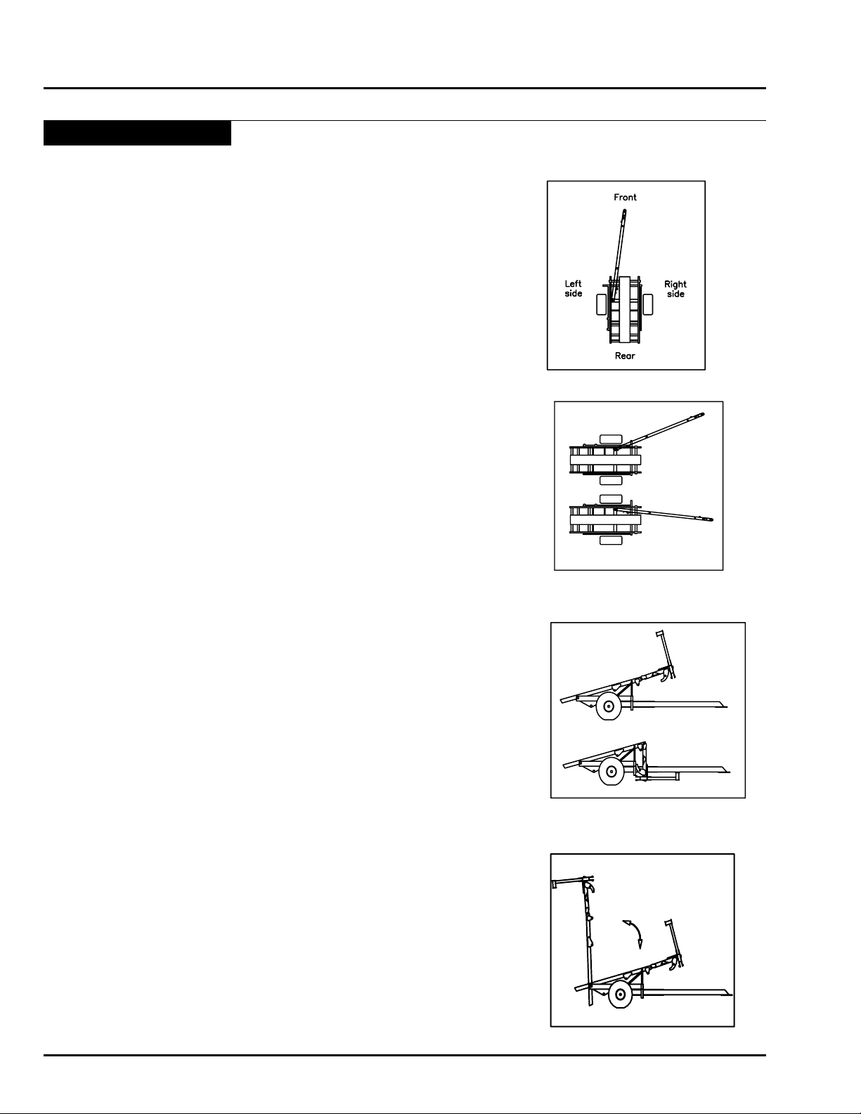
Hitch Offset — Hitch Inline
Loader Raised — Loader Lowered
Bed Raised - Bed Lowerd
Machine Conventions
Auto Align Bale Runner Directional Conventions
“Right and Left” The right and left side of the Bale Runner is your
right or left when standing behind the Bale Runner
and looking toward the front of the machine.
“Front and Rear” The front is the high end of the bed. The rear of the
Bale Runner is the low end of the bed.
“Offset” The machine configuration when the hitch is
maneuvered to allow machine to pick up bales. The
end of the hitch is to the left of the left side tire.
“Inline” The machine conguration when the end of the hitch
is centered between the wheels of the Bale Runner.
“Raise the Loader” Move the hydraulic control to move, or physically lift
the loader into the raised position.
“Lower the Loader” Move the hydraulic control to move, or allow loader
to rest in the lowered position.
“Raise the Bed” Move the hydraulic control to move the bed into the
raised position.
“Lower the Bed” Move the hydraulic control to move the bed into the
lowered position.
5-4 June 2015 HD4SR & 12SR
Page 41
Hooking Up for the First Time
Use the following outline as a checklist to ensure your
Auto Align Bale Skoop is properly set up for use.
Operation
WARNING: Remember to turn off
hydraulic system and tractor and remove
key from ignition before working on the
Bale Skoop.
Parts Needed
1 Hitch Bolt 1 1/4” x 9” special
2 Hitch Washer 1 1/4” at washer
1 Hitch Nut 1 1/4” plain
1 Hitch Jam Nut 1 1/4” special
1 Hitch Spacer Bolt 5/8” x 8”
1 Hitch Spacer 3/4” ID x 3 9/16” tube
2 Hitch Plates 1/2” x 3” x 6 3/8”
1 Spacer Bolt Nut 5/8” Nylock
1 Bolt Safety Pin 3/16” Snaplock Pin
1 Warning Light Box Special
6 Male Hydraulic Connections*
7 Gallons of Hydraulic Fluid* Approximate Amount
* Supplied By Dealer or Customer
Warning
Remember to turn off hydraulic system and
tractor and remove key from ignition before
working on the Bale Skoop.
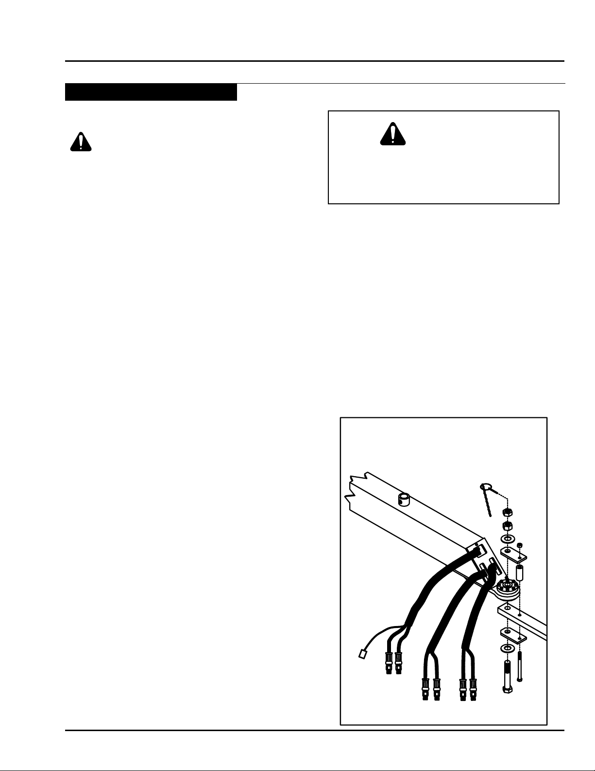
Attach Bale Skoop to Tractor
• Attach male hydraulic connector* to hitch hydraulic
hoses using thread sealer.
• Line up the ball hitch on the machine with the tractor
draw bar. Secure the machine to the tractor with the
1 1/4” x 9” bolt threaded up through (1)-1 1/4” at
washer, lower hitch plate, tractor draw bar, ball, the
upper hitch plate, (1)-1 1/4” at washer, 1 1/4” nut, 1
1/4” jam nut, and insert bolt safety pin through eyelet
in bolt.
• Secure the hitch plates into position with the (1)-5/8”
x 8” bolt, (1)-3/4” ID x 3 9/16” tubing, and (1)-5/8”
nylock nut.
HD4SR & 12SR June 2015 5-5
Page 42
Operation
Hooking Up for the First Time - Continued
Connect Safety Chain
CAUTION: Operating Bale Skoop
without safety chain connected to tractor
can be hazardous. Always attach safety
chain to tractor.
• Secure hitch safety chain to tractor or tractor draw
bar. Note: Chain should be loose enough to allow
tractor to turn without allowing chain to drag on the
ground.
• Remove jack from the side of the hitch by removing
the retaining pin. Re-secure it to the top of the hitch.
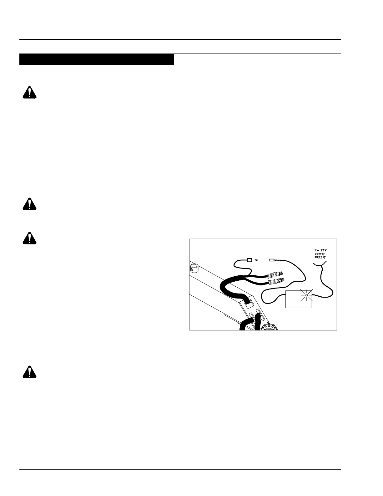
Hooking Up Warning Light Assembly
CAUTION: DO NOT operate machine
without the Warning Light Assembly
installed and operational.
CAUTION: Use care when working with
electricity. Disconnect battery of tractor
before attempting to connect Warning
Light Assembly.
• Run the connecting lead of the Warning Light
Assembly from the cab of the tractor to the front of
the hitch.
• Connect to the Micro-switch wire.
• Connect the positive and negative leads to an
appropriate 12V power source.
Note: Be sure to ground properly to prevent
electrocution.
Lubricate Joints
WARNING: Be sure the loader is resting
on the hitch or in its lowest position while
greasing machine.
• Grease all joints using all-purpose, non-clay
based grease as shown in the “Maintenance and
Adjustment” section of the Owner/Operator’s Manual.
5-6 June 2015 HD4SR & 12SR
Page 43
Hooking Up for the First Time - Continued
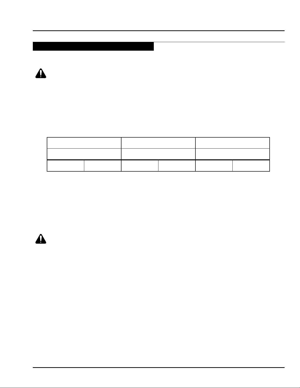
Loader Circuit Hitch Cylinder Bed Cylinder
Lever 1 Lever 2 Lever 3
GREEN RED YELLOW WHITE BLUE BLACK
Prime Hydraulic System
CAUTION: Check hydraulic fluid frequently
while priming system.
• Connect hydraulic hoses to tractor as paired. (See
Chart Below) Remove hitch safety pin and store in
pin holder.
• Be sure to use a good quality oil that meets or
exceeds the specifications from the tractor’s
manufacturer.
Operation
• Raise the loader completely and offset the hitch. With
the hitch completely offset, cycle the loader circuit.
Remember that the alignment arms, loader Cylinders
and grab hooks are all on this circuit. Cycle until the
loader and all its functions operate smoothly. The
operation of controls on the following page will be
helpful.
WARNING: Keep the hitch in the OFFSET
position while cycling the loader. Severe
damage may occur if components collide.
• Check the hydraulic oil level in the tractor.
• Leave the loader in the Raised position, and cycle
the hitch until it operates smoothly.
• Check the hydraulic oil level in the tractor.
• After priming the hitch, cycle the bed until uid has
completely lled the system.
• When the bed is raised, and the Bale Skoop is parked
on level ground, be sure the forks on the back of the
bed set down rmly on the ground. If they don’t you
will need to raise the hitch by turning over the drawbar
on the tractor.
• Lower the bed and the loader and check the hydraulic
oil level in the tractor.
HD4SR & 12SR June 2015 5-7
Page 44

Operation
Pre-Operation Checklist
Before operating Bale Skoop check the following items:
Pre-Operation Check
Lug nuts Check that all lug nuts are present and torqued to the appropriate foot/lbs.
Pin retaining bolts Check for any missing or loose bolts or pins, replace or tighten as necessary.
Hydraulic hoses Inspect all hydraulic hoses and replace any worn hoses. Remember: Use a piece
Jack Check that jack has been moved to the upper jack stud on TOP of the hitch.
Hitch Safety Pin If traveling, check that the Hitch Safety Pin is securely in place. If gathering or
Warning Light Check that the Warning Light functions properly.
Lighting Make sure the lighting is hooked up and functioning properly.
Tire Pressure Check tire pressure to make sure it is within the specied range given on page 2-2
of cardboard or wood to look for leaks, replace leaky hoses.
stacking, check that the Hitch Safety Pin has been removed.
in the “Machine Specications” section.
5-8 June 2015 HD4SR & 12SR
Hitch Connection Check the bolt system that connects the stacker to the tractor drawbar. A loose
connection will wear faster and possibly uncouple.
Page 45
Operation of Controls
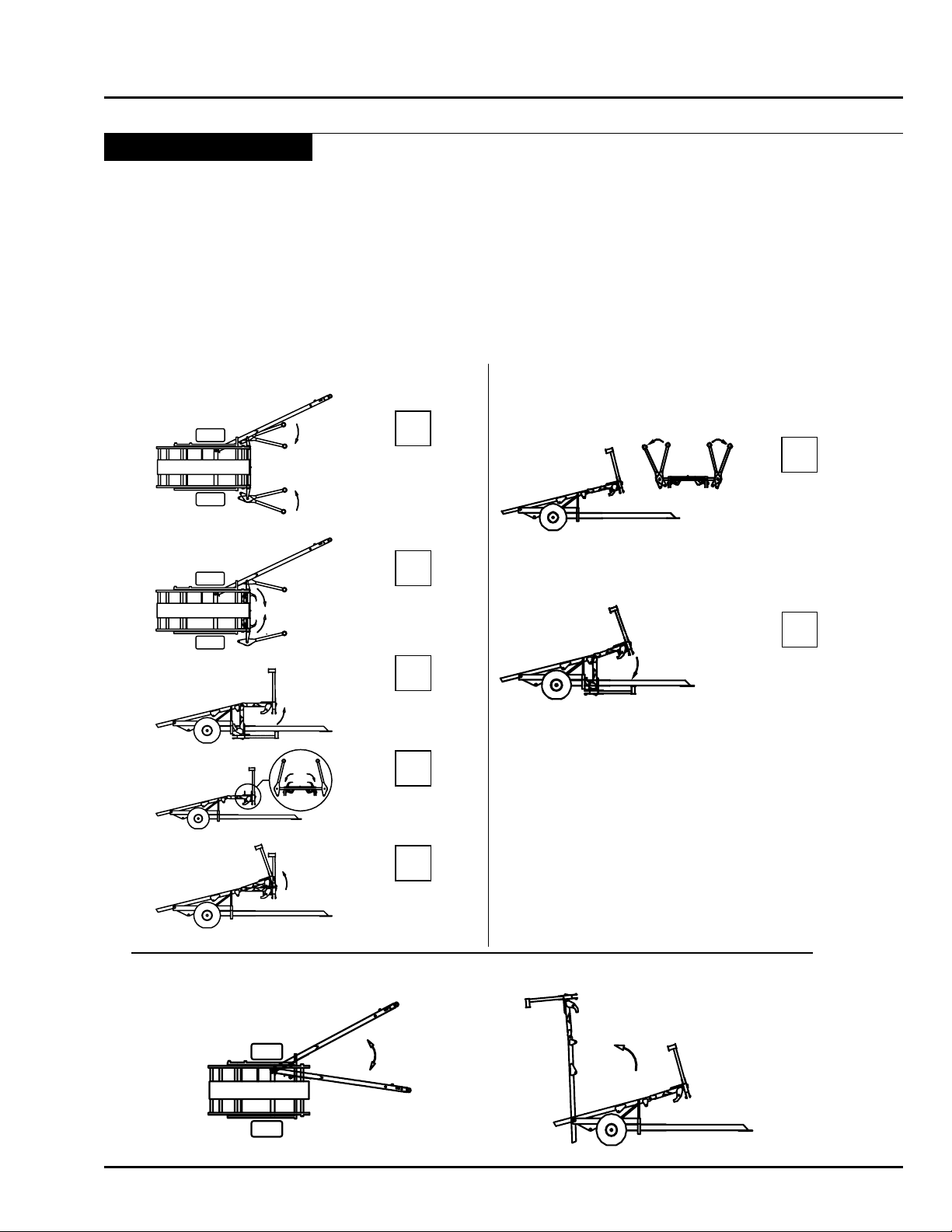
UP SEQUENCE DOWN SEQUENCE
Alignment Arms
Squeeze Bale
Grab Hooks
Engage Bale
Loader Raises to
Level Position
Grab Hooks
Disengage Bale
Loader Raises to
Full Height
Lever 2 Controls Hitch offset motion.
Lever 3 Elevates Bed.
Alignment
Arms Open
Loader Lowers
to ground
Lever 1 Controls Alignment Arms, Loader and Grab Hooks (12SR).
1
2
3
4
5
1A
2A
Setting up the Lever Controls
Although you may have your preference of tractor lever control setup, the typical lever conguration is “forward is
for lowering”, and “back is for lifting”. If this is not your standard be aware that the lever operation instructions below
represent this conguration.
Hydraulic Sequencing and Lever Operation
Operation
HD4SR & 12SR June 2015 5-9
Page 46
Operation
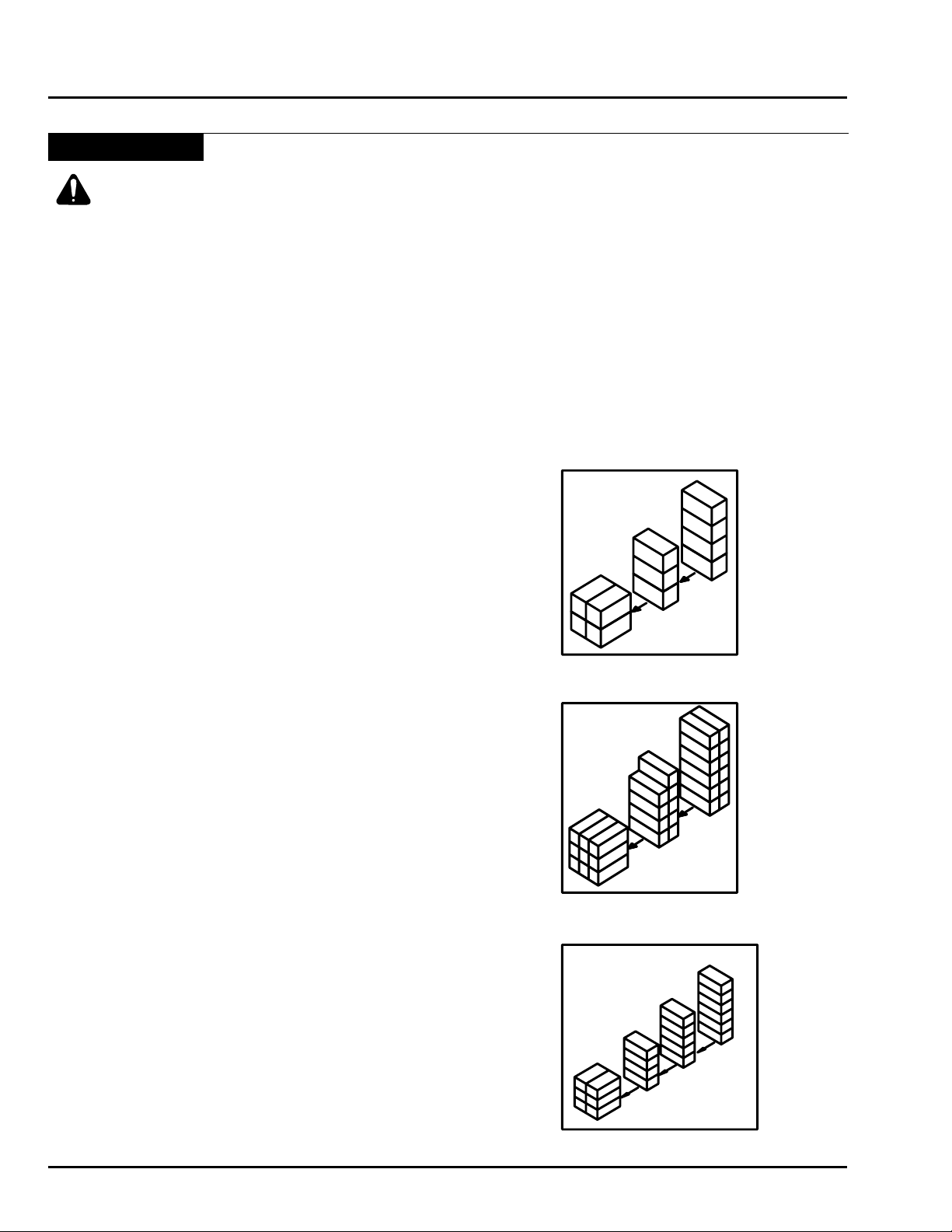
1 Ton Backstop
½ Ton Backstop
3X4 Backstop
Building Stacks
CAUTION: Return stacker to the “in-line”
position when moving between bales in
field and stack. This reduces the chance
of running over anybody or anything in
the field.
Starting Stacks
1. Choose a level area, with enough room to maneuver
a tractor and Bale Skoop even after the stack is
nished. Note: If completely level ground is not
available, then build your stack uphill (front of tractor
and Bale Skoop facing uphill).
2. Begin stack by building a “backstop”. The proper
backstop should be built to withstand backing into the
stack every time a load is delivered. We recommend
the following back stop congurations:
1 Ton Squares: A 2 bale by 2 bale square set at one
end, perpendicular to the length of the bales in the
stack. The rst load in the stack should be only 3
bales tall.
½ Ton Squares: A 3 bale by 3 bale square set at one
end, perpendicular to the length of the bales in the
stack. The rst load in the rest of the stack should
only be 2 bales by 4 bales, with one extra in the
fth tier.
3 X 4 Bales: A 2 bale by 3 bale stack set at one end,
perpendicular to the length of the bales in the stack.
The rst load in the stack should be 4 bales high,
the second 5 bales high, and the rest should be 6
bales high.
5-10 June 2015 HD4SR & 12SR
Page 47

Stacking
1. After the last bale(s) is/are picked up, raise the loader
all the way up. This squeezes the load between
the forklift teeth and the alignment arms making a
compact load.
2. Position the tractor and Bale Skoop in front of the
backstop.
3. Raise the bed to 70 or 80 degrees (so it is almost
vertical, but the weight of the bales is still clearly
against the bed).
4. Back up until the corner of the bottom bale on the
Bale Skoop comes into contact with the back stop.
5. Continue to raise the bed and back up until the load
is vertical. Important: It is critical that the rst load
into the stack is vertical. To avoid the stack tipping
over, DO NOT ALLOW THE BED TO GO PAST
VERTICAL on the rst load.
6. Lower the loader to release the alignment arms from
the stack.
7. Pull forward slowly, lower the bed all the way, and go
and retrieve another load.
Operation
CAUTION: Avoid overhead wires
to prevent serious injury or death.
Electrocution can occur without direct
contact.
CAUTION: Keep bystanders at least
twenty-five feet away from an operating
machine or stacked hay.
Note: Be sure the loader is raised enough not to hit
the hitch when the bed is lowered all the way.
Gathering Bales
Approaching Bales
1. The easiest way to pick up bales is by driving the Bale
Skoop perpendicular to the path of the baler.
2. Before arriving at a bale “offset” the hitch and lower
the loader all the way down until it is perpendicular
to the ground.
3. Bales are picked up on their 8 foot side.
4. The Auto Align system will allow the operator to
approach the bale from almost any direction.
WARNING: Keep bystanders at least
twenty-five feet away from an operating
machine or stacked hay.
WARNING: Avoid rocks rough terrain,
steep slopes, banks and drop offs when
possible. Always maneuver tractor at safe
speeds.
HD4SR & 12SR June 2015 5-11
Page 48
Operation
Stair-stepping ½ Ton Bales
Gathering Bales - Continued
Loading Bales
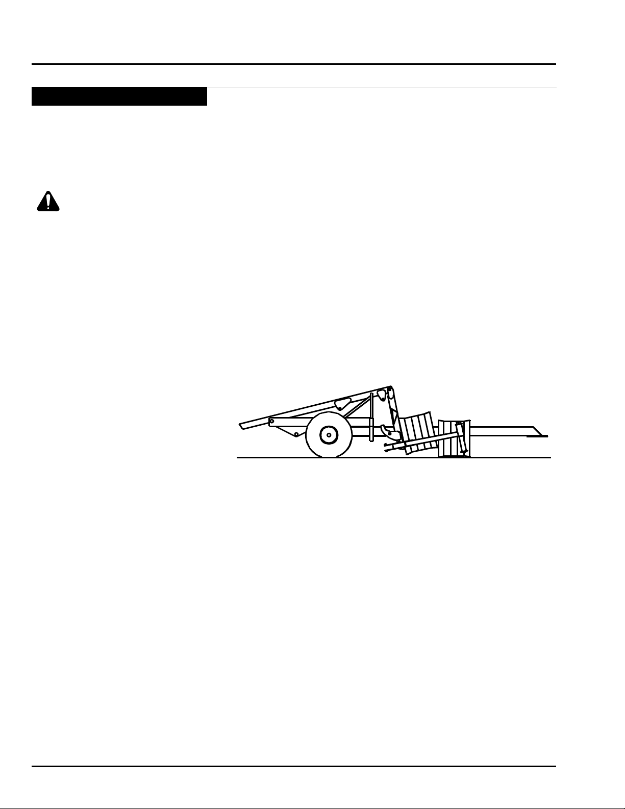
1. When the bale is between the alignment arms and
against the loader raise the loader. The alignment
arms will automatically squeeze the bale and then
the loader will raise.
CAUTION: The first bale or pair of bales
that is loaded onto the bed of the Bale
Skoop makes it very front heavy. Caution
must be exercised when the Bale Skoop
is in this position.
If operating a 12SR model Auto Align Bale Skoop
2. When the loader is raised, the alignment arms will
squeeze the bale, and the grab hooks will come from
behind the loader to hold the rst bale.
3. The alignment arms can then be opened to retrieve
the next bale.
Note: Keep the end of the alignment arms 12
to 14 inches (30 - 35 cm)off the
ground in order to pick up the
second bale slightly lower (6-15
inches(15 - 35 cm)) than the rst.
This stair-step will help allow the
bale to slide back without tipping
over.
Note: Keep alignment arms on the rst bale closed
until you get to the second bale.
4. Properly adjusted grab hooks will automatically
disengage when the loader is raised to a horizontal
position.
Operating all models of Auto Align Bale Skoops
5. Raise the loader until it is all the way up. Begin to
lower the loader and the alignment arms will open
allowing the bales to slide to the rear of the bed.
6. Repeat as many times as desired, or until the load
is complete (HD4SR full load is 4 bales (with 4x4
bales), 12SR full load is 12 bales (with 3x3 bales),
with 3 x 4 bales, the full load for both machines is 6
bales). Note: After the last bale(s) is/are picked up,
the loader should not be lowered.
7. Move hitch into the “inline” position before traveling
to the stacking area.
5-12 June 2015 HD4SR & 12SR
Page 49

Transporting Bale Skoop
WARNING: Attach safety chain to Bale
Skoop and Tractor before moving on
highway.
CAUTION: Exceeding speeds of 20
mph (32 km/h) is not legal or safe on
public roads. DO NOT exceed 20 mph
(32 km/h) with this machine.
WARNING: Use Hitch Safety Pin to
lock hitch in the in-line position before
transporting Bale Skoop on public roads.
This will secure hitch in case of accidental
activation or failure of hitch cylinder.
REMEMBER: When transporting any piece of
oversized equipment:
• Be familiar with local laws by contacting local
authorities before transporting Bale Skoop on public
roads. Obey all regulations as they pertain to the
Bale Skoop. The specications at the front of the
manual contain most of the information that may be
needed.
• This machine is equipped with lighting, markings,
and signs in compliance with standards published
by the American Society of Agricultural Engineers
for Slow Moving Agricultural Implements on Public
Roadways.
• Use ags, warning lights and slow moving vehicle
signs as they are needed. Flag-persons may be
required by local authorities and may be helpful even
if they aren’t required.
• Always remember the extra width of the Bale Skoop.
The wheels on the Bale Skoop are approximately 10
feet 8 inches (325.1 cm) wide with the implement
tires, 10 feet 8 inches (325.1 cm) wide with the truck
tires, and 11 feet 3 (342.9 cm) inches wide with the
high otation Terra tires.
• Drive carefully at an appropriate speed for the
size and weight of the Bale Skoop. Allow for the
extra length of the trailer when making corners.
Reduce speed when navigating corners to prevent
overturning machine. Link brakes to prevent loss of
control during panic braking.
• Plan route to avoid heavy trafc. Drive in a courteous
manner.
• Never drink and drive!
Operation
HD4SR & 12SR June 2015 5-13
Page 50
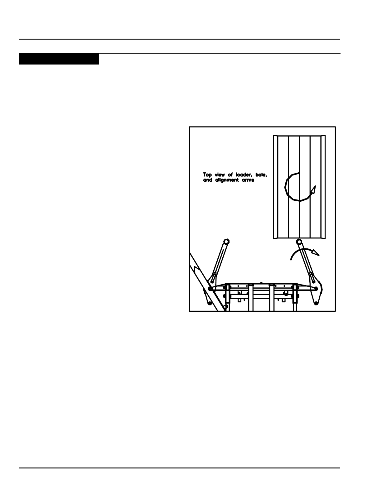
Operation
Tips and Techniques
It takes some time, generally about a week, for an
operator to get used to the controls, the movements,
and the capabilities of the Auto Align Bale Skoop.
Rotating Bales
• If approaching the bale “end-on” is desired, the bale
may be rotated, or spun, by closing the alignment
arms slightly and bumping the end of the bale with
the right alignment arm. When contact is made,
open the arms to push the end to the right causing
the bale to rotate into the loader.
Quarter Turning Bales
• To quarter turn a bale on the ground raise the loader
until the alignment arms squeeze together. With the
ends of the alignment arms positioned about halfway
up the side of the bale, move forward, while raising
the loader.
Note: Quarter turning with a Bale Skoop is very time
consuming and is not recommended for a larger
number of bales in a row.
• To quarter turn a bale with a 12SR model Bale Skoop
grab the rst bale before attempting to quarter turn
the second bale.
Note: Make sure the feet on the slider pipes of the
12SR grab under the edge of the bale, otherwise
they may catch a string.
Repositioning Bales
• If bales are located in a corner or tight place, the
alignment arms can be used to grab a bale and
reposition it in a better working location.
Tipping or Rolling Bales
• If the bales do not have enough stair-step the bales
might roll when traveling down the bed. If you have
to x the amount of stair-step after picking two bales
into the loader just raise the loader a few inches (4”15” (10 - 38 cm)), then open the alignment arms so
the second bale can slide down in front of the rst.
Raise the loader again and the alignment arms will
re-squeeze the bale.
5-14 June 2015 HD4SR & 12SR
Page 51
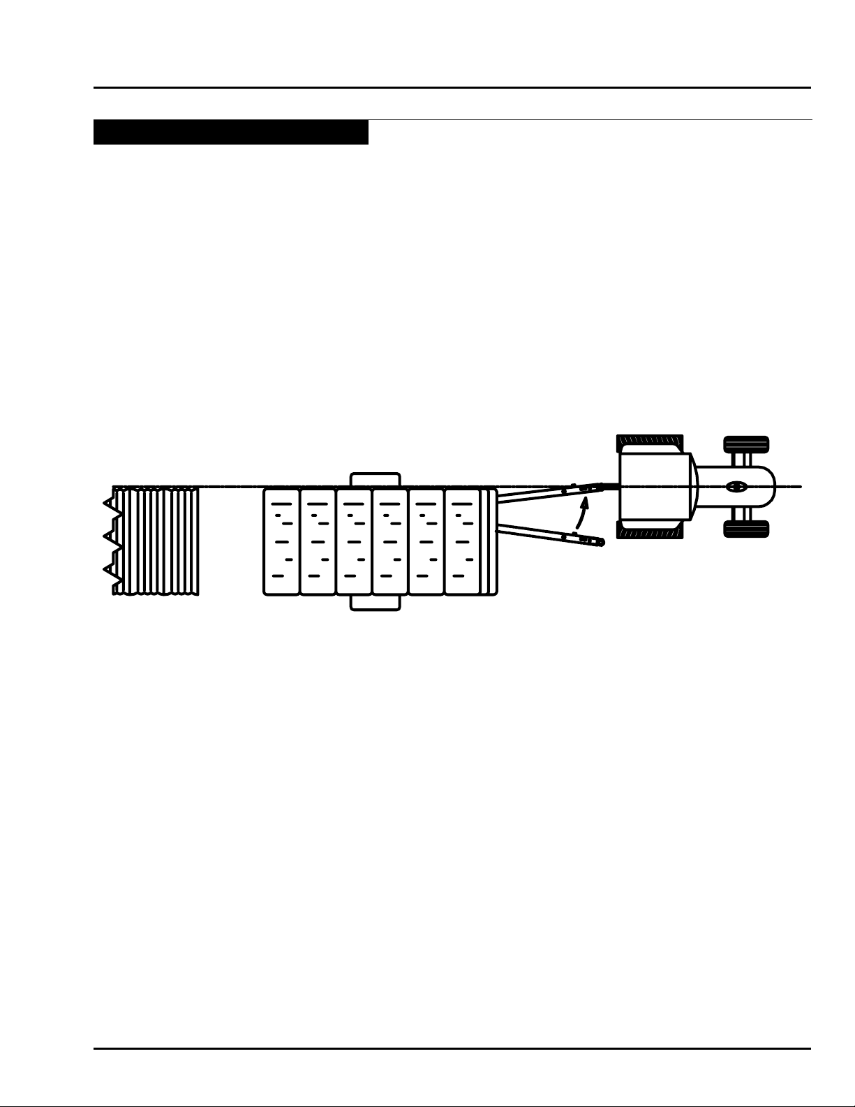
Lining up the center of the tractor with the edge of the stack
Tips and Techniques - Continued
• If the loader has been lifted too far and the grab
hooks have disengaged without enough stair-step
between the bales it is possible to get the bales to
slide on the bed. Most of the time if the bales are
rolling it is because they catch at the hinge between
the bed and the loader. Raise the loader until it is
exactly in-line with the bed and open the alignment
arms.. (Sometimes with wet bales this is the only
way to get the bales to slide.)
Stacking
• For better visibility while building stacks, center the
tractor against the edge of the stack, with the hitch
slightly offset; it is much easier to see what you are
doing. . . stacks turn out straighter too!
Operation
• Fine tune your stack by making minor adjustments
in your steering with the hitch control.
• The bales should be stacked on level ground. When
stacking on a slight incline, stack with the tractor
facing uphill. Stacking downhill or on a slight side
incline will make it difcult to build good stacks.
• If the stack is not tight enough, raise the bed all the
way up, pull the tractor and Bale Skoop forward three
feet, and back into the stack to push the bales tight.
HD4SR & 12SR June 2015 5-15
Page 52

Operation
Bales Size
HD4SR
Stack Size
4SR Changes
Needed
12SR
Stack Size
12SR Changes
Needed
Freeman 3x4
38"x46"
(4) On strings
5 high
x
1 deep
(1) Standard
configuration
5 high
x
1 deep
(5) Remove bed
extensions
(2) Disable grab
hooks
NH 595 3x4
35"x47"
(4) On strings
6 high
x
1 deep
(5) Add bed
extensions
6 high
x
1 deep
(2) Disable grab
hooks
Hesston 4900
51"x48"
(4) On or off
strings
4 high
x
1 deep
(1) Standard
configuration
4 high
x
1 deep
(5) Remove bed
extensions
(2) Disable grab
hooks
(3) Watch alignment
arms
Hesston 4755
35"x32"
(4) On strings
6 high
x
1 deep
Call ProAG
Designs
6 high
x
2 deep
(1) Standard
configuration
D1000/D800
24"x36"
(4) Off strings
N/A N/A
5 high
x
2 deep
(5) Remove bed
extensions
(3) Watch alignment
arms
Note: Other manufacturer’s balers create the same size bales - these were used for illustration purposes only.
Tips and Techniques - Continued
Stacking bales of different sizes
Table Key:
(1) Standard Conguration
The way the machine is normally set up.
(2) Disable Grab Hooks
Turn Valve #5 on the manifold valve in two turns.
(3) Watch Alignment Arms
The alignment arms are longer than the bales and will contact the stack if they are not opened up before the bed
is raised to its maximum height.
(4) On/Off Strings
The bales come out of the baler “On Strings”. If you want to pick up the bales “Off Strings” you must have a turner
for your baler.
(5) Remove/Add Bed Extensions
With the hitch offset and the loader in its lowest position, remove the pin from the bottom of the bed extension
and lift the extension off the machine. Turn the bed extension 180 degrees so that the front of the extension is
facing the other direction, place the extension back on the machine, and reinsert the pin.
5-16 June 2015 HD4SR & 12SR
Page 53

Section 6: Maintenance
Maintenance
Section 6:
Maintenance 6-1
Section Contents
General .............................................................................................................................6-2
Safety ...............................................................................................................................6-2
Tighten Bolts .....................................................................................................................6-3
Tires ..................................................................................................................................6-3
Preventative Maintenance ................................................................................................6-4
Hydraulic System Preventative Maintenance ...................................................................6-4
Hydraulic Pressure Relief .................................................................................................6-5
Daily Maintenance ............................................................................................................6-6
Daily Check ................................................................................................................6-6
General Maintenance .......................................................................................................6-7
General Check ...........................................................................................................6-7
To tighten Alignment Arm Chains ...........................................................................6-7
Cylinder Repair ..........................................................................................................6-7
Bed Extensions ..........................................................................................................6-7
Electrical Maintenance .....................................................................................................6-8
Warning Box System ..................................................................................................6-8
Basic Maintenance and Notes ...................................................................................6-8
Wheel Bearing Adjustment ...............................................................................................6-8
Wheel Bearing Adjustment Procedure (Double Nut Arrangement) ............................6-8
Electrical Diagrams ...........................................................................................................6-9
Lubrication Points ...........................................................................................................6-11
Lubricants ................................................................................................................6-11
Bolt Torque Specication Chart ................................................................................6-12
Year End Maintenance ...................................................................................................6-13
Storage.....................................................................................................................6-13
Preventative Maintenance ........................................................................................6-13
HD4SR & 12SR June 2015 6-1
Page 54
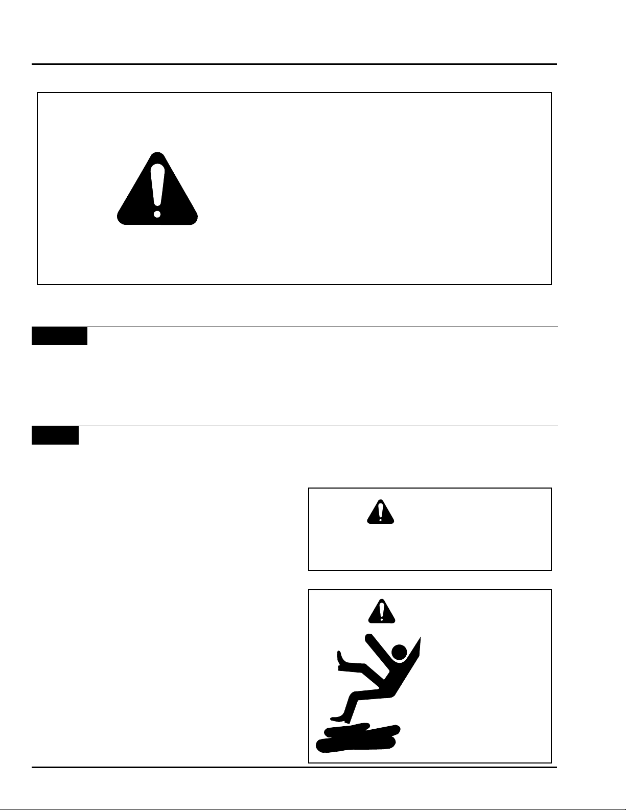
Maintenance
CAUTION
BE ALERT
General
This section deals with two goals, maximum life and
dependable operation. Adopt a regular maintenance
and lubrication program. Care and sufcient lubrication
is the best insurance against delays.
SAFETY FIRST
REFER TO SECTION 1 AND REVIEW
ALL SAFETY RECOMMENDATIONS.
Safety
• Always shut off the tractor and remove key before
dismounting.
• Guard against hydraulic high pressure leaks with
hand and face protection.
• Never work under the implement unless it is in the
down position or securely blocked in place. Do not
depend on the hydraulic system to support the frame.
Warning
Securely support any machine elements that
must be raised for service work.
Caution
Keep service area clean
and dry. Wet or oily
oors are slippery.
6-2 June 2015 HD4SR & 12SR
Page 55

Tighten Bolts
• Before operating the unit.
• After the rst two hours of operation.
• Check tightness periodically thereafter.
• Use Bolt Torque Chart on page 6-13 for correct
values on various bolts.
• Note dashes on hex heads to determine correct
grade.
Note: DO NOT use the values in the Bolt Torque
Chart if a different torque value or tightening
procedure is given for a specic application.
• Fasteners should be replaced with the same or higher
grade. If higher grade is used, only tighten to the
strength of the original.
Maintenance
Tires
• Inspect tires and wheels daily for tread wear, side
wall abrasions, damaged rims or missing lug bolts
and nuts. Replace if necessary.
• Tighten wheel bolts - refer to Bolt Torque Chart.
• Check tire pressure daily, when tires are cold. Tire
pressures for specic tires are listed in the “Machine
Specication” section at the front of this manual.
• Correct tire pressure is important.
• Do not inate tire above the recommended pressure.
Warning
After the rst 100 hours of use, re-torque all
wheel lug nuts.
Caution
Tire replacement should be done by trained
personnel using the proper equipment.
HD4SR & 12SR June 2015 6-3
Page 56

Maintenance
Preventative Maintenance
Before operating your Bale Skoop carefully inspect the entire machine, and its components for any sign of excessive
wear or weakness. Always follow the Daily Maintenance, General Maintenance, and Year End Maintenance Checklists
to allow for early detection of possible hazards.
WARNING: Always wear eye protection and proper protective clothing while performing
maintenance on the Bale Skoop. Protective clothing includes, but is not limited to; heavy
pants and shirt, steel toed boots, and gloves.
WARNING: When working with hydraulic fluid you should wear rubber gloves to prevent oil
from getting in cuts and scratches in your skin and causing infections or allergic reactions.
Hydraulic System Preventative Maintenance
DANGER: Remember to turn off hydraulic system and tractor and remove keys from ignition
before servicing the Bale Skoop. The bed and loader should be lowered to their lowest
position or securely blocked in position.
• Maintain tractor hydraulic system and uid according to manufacturers specications. Always use a good quality
hydraulic uid.
• Check the uid level in the tractor with the bed and loader cylinders retracted.
WARNING: Hydraulic fluid escaping under pressure can easily penetrate skin. Openings in
the skin and minor cuts are susceptible to infection from hydraulic fluid. If injured by escaping
hydraulic fluid, see a doctor at once. Without immediate medical treatment, serious infection
and allergic reaction can occur.
• Check for chafng or kinking of the hydraulic hoses, these are a source of leaks in hoses.
• Check hoses and cylinders for leaks and repair as necessary. Remember that hydraulic uid escaping under
pressure can penetrate human skin. Use a piece of cardboard or wood to look for a suspected high pressure leak.
• Replace all hoses or hydraulic components that show any sign of wear, cracks,leaking, etc.
6-4 June 2015 HD4SR & 12SR
Page 57

Maintenance
Hydraulic Pressure Relief
IMPORTANT! RELIEVING HYDRAULIC PRESSURE FROM LINES
Repairs to hoses and cylinders will usually require disconnecting a tting connection. Fittings should not be
disconnected until the pressure in the hydraulic circuit has been relieved. Follow this procedure to relieve pressure
in the hydraulic lines.
WARNING: Hydraulic fluid escaping under pressure can easily penetrate skin. Openings in
the skin and minor cuts are susceptible to infection from hydraulic fluid. If injured by escaping
hydraulic fluid, see a doctor at once. Without immediate medical treatment, serious infection
and allergic reaction can occur.
WARNING: Always wear eye protection and proper protective clothing while performing
maintenance on the Bale Skoop. Protective clothing includes but is not limited to; heavy
pants and shirt, steel toed boots, and gloves.
WARNING: When working with hydraulic fluid you should wear rubber gloves to prevent oil
from getting in cuts and scratches in your skin and causing infections or allergic reactions.
1. Be sure bed is resting on its rest and loader is resting on the hitch or in its lowest position.
2. Park the tractor and Bale Skoop on level ground, place the transmission in park, set the parking brake, turn
off the tractor, and remove the key. When the tractor is off, move each of the hydraulic levers forward and back
approximately four times.
3. Uncouple the hoses from the tractor. Slowly unscrew the male hydraulic tips on the ends of the stacker hydraulic
hoses, turning them 1/8 th of a turn at a time watching for oil to start leaking out.
4. Use a bucket to catch leaking hydraulic uid.
5. Crack the hydraulic lines to the loader cylinders as they can have oil under pressure caught by the load check
valve.
Warning
HIGH-PRESSURE FLUID HAZARD
To prevent serious injury or death:
• Relieve pressure on hydraulic system before servicing or
disconnecting hoses.
• Wear proper hand and eye protection when searching for
leaks. Use wood or cardboard instead of hands.
• Keep all components in good repair.
HD4SR & 12SR June 2015 6-5
Page 58

Maintenance
Daily Maintenance
WARNING: After the first 100 hours of use, re-torque all wheel lug nuts.
Daily Check
Lubricate Lubricate all grease points with all-purpose, non-clay based grease. See
section for location of grease zerks.
Hitch Connection
Inspect Pins
Inspect Plastic
Inspect Hydraulics
Clean
Check the bolt system that connects the stacker to the tractor drawbar. A loose
connection will wear faster and possibly uncouple.
Check to make sure all pins and bolts are secure in their proper places. Inspect the
pivot pins for wear and replace as necessary.
Check all plastic wear plates for wear or breakage. See section in general
maintenance.
Inspect all hydraulic hoses, ttings, and couplings for signs of wear and x as
necessary. Check hydraulic uid in tractor and general hydraulic system as outlined
above.
Keep the Bale Skoop clean and free from mud and dirt, especially around hydraulic
cylinder rods and moving parts.
“Lubrication”
Axle Bearings
Wheel Lug Nuts
Tire Air Pressure
6-6 June 2015 HD4SR & 12SR
Check the oil level in the axle hubs and ll with 80-90 gear lube as necessary.
Examine the wheel lug nuts making sure all are tight and none are missing.
Check air pressure in tires. Tire pressures for specic tires are listed in the “Machine
Specication” section at the front of this manual.
Page 59

Maintenance
General Maintenance
General Check
• Lug nuts should be tightened to 450-500 ft-lbs.
• Axle U-bolts should be tightened to 628 ft-lbs. This amount of torque will crush the threads so the U-bolts cannot
be re-used.
• Alignment arm chains should be kept tight to prevent cracking of the loader. Check the chain tightness by visually
inspecting the chains when the loader is fully raised. The chains should have little or no slack.
To tighten Alignment Arm Chains
1. Jack up the ends of the alignment arms and block them in place. This should create the most slack in the chain.
2. Release the safety latch and unhook the grab hook. Determine the link that would eliminate the most slack in
the chain.
3. Remove the double clevis pin in the end of the chain, hook the grab hook on the desired link, and re-lock the
safety latch.
4. Re-install the pin on the double clevis on the end of the chain through the pad eye on the alignment arm.
• Check all plastic wear surfaces used in the machine. These parts are located at the hitch pivot point, between the
hitch and the frame, at the alignment arm pivots, and in the grab hook pivots (if 12SR model).
• Periodically check all bolts. Use grade eight bolts for replacements. A torque chart is provided on page 6-12.
Cylinder Repair
The diagnosis and repair of the hydraulic cylinders on the Auto Align Bale Skoop should only be attempted by a
qualied service technician familiar with this type of repair.
Bed Extensions
The bed extensions are used to hold the fth tier in a load, depending on the dimensions of the bales being stacked.
Refer to the chart on page 5-16 to determine if your application requires the use of bed extensions. The bed extensions
can easily be removed, turned around, and re-pinned to the bed if it is desired to stack a different sized bale.
HD4SR & 12SR June 2015 6-7
Page 60

Maintenance
Electrical Maintenance
Electrical components on the SR Bale Skoop do not need regular maintenance unless wires or cable are worn
or broken. This section briey outlines the function of the electrical systems and gives some basic guidelines for
maintenance and repair.
Warning Box System
This is a simple system used to warn the operator that the hitch is not in the in-line position. It consists of a micro
switch mounted on the frame of the stacker, a wire that runs the length of the hitch, and a box with a light which is
mounted in the cab.
Basic Maintenance and Notes
• Always check the wires for wear from rubbing on different components. When wear is detected, move the wires
or shield them.
• When trouble shooting, always check the wires for good connections.
• Use the Electrical Diagrams to rebuild wires if needed.
Wheel Bearing Adjustment
Wheel Bearing Adjustment Procedure (Double Nut Arrangement)
1. Prior to installing any wheel-end fasteners, make sure the spindle area is free of dirt and debris. As well, make
sure all nuts and washers are free of dirt. Clean mating surfaces are important for proper wheel-end assembly.
2. After properly installing the bearing cones and wheel-end seal onto the spindle, and the wheel-end is slid onto the
spindle, tighten the inner spindle nut with a torque wrench to 150-200 ft. lbs. to set the bearings and wheel-end.
CAUTION: DO NOT USE AN AIR IMPACT WRENCH TO TIGHTEN THIS NUT!
3. Loosen this inner nut to allow the brake drum to rotate freely. Backing off one (1) full turn is recommended.
4. Re-tighten the inner spindle nut to 50 ft. lbs. by hand using a torque wrench to position the bearings for nal
adjustment. CAUTION: DO NOT USE AN AIR IMPACT WRENCH TO TIGHTEN THIS NUT!
5. Back the inner spindle nut off 1/4 turn.
6. Install the retaining fastener or fasteners onto the spindle according to the fastener used. If washers are used,
be sure they are facing in the right direction and are clean. Make sure any washers with dowels t properly into
the mating holes.
7. Install the outer spindle nut. Using a torque wrench, tighten this nut to 250-300 ft. lbs. Resulting end play should
be .001” - .005”.
Note: If end play is not .001” - .005”, disassemble and repeat this procedure.
6-8 June 2015 HD4SR & 12SR
Page 61
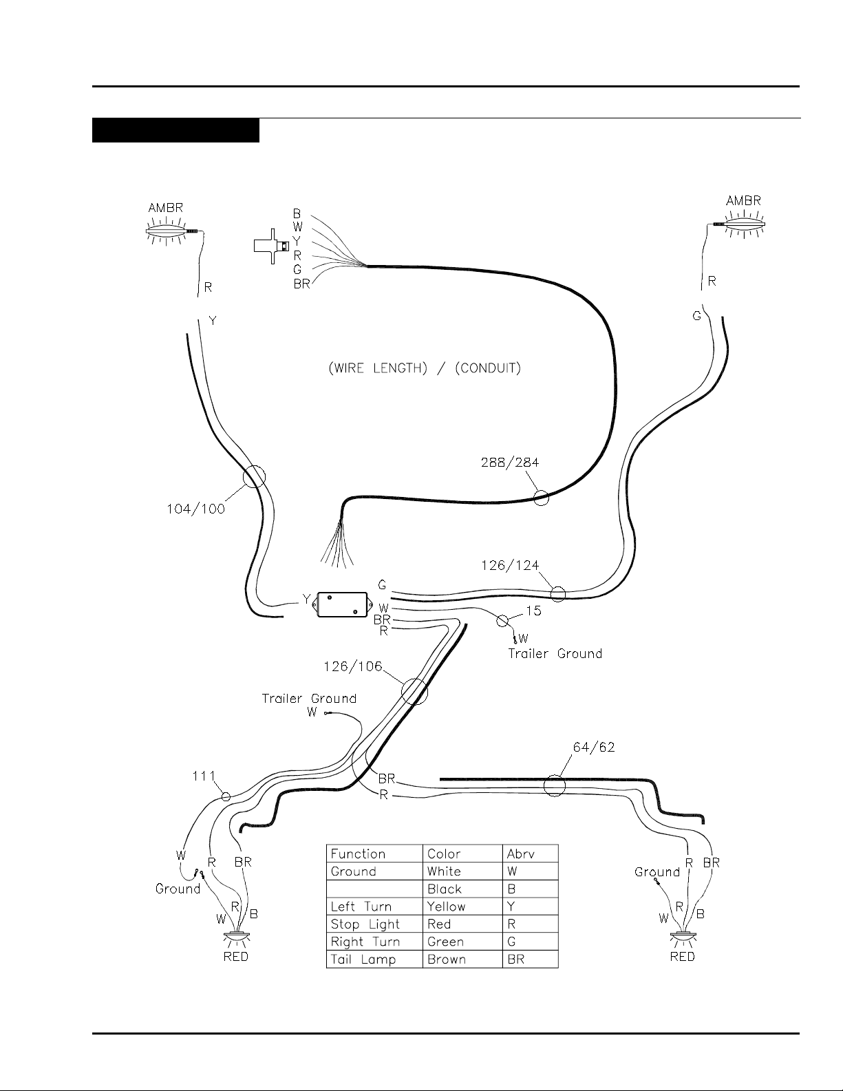
Electrical Diagrams
Maintenance
HD4SR & 12SR June 2015 6-9
Page 62
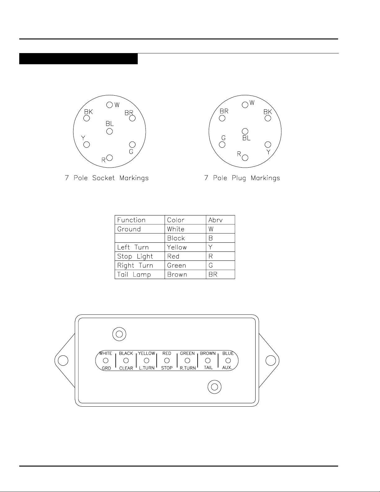
Maintenance
Electrical Diagrams - Continued
6-10 June 2015 HD4SR & 12SR
Page 63
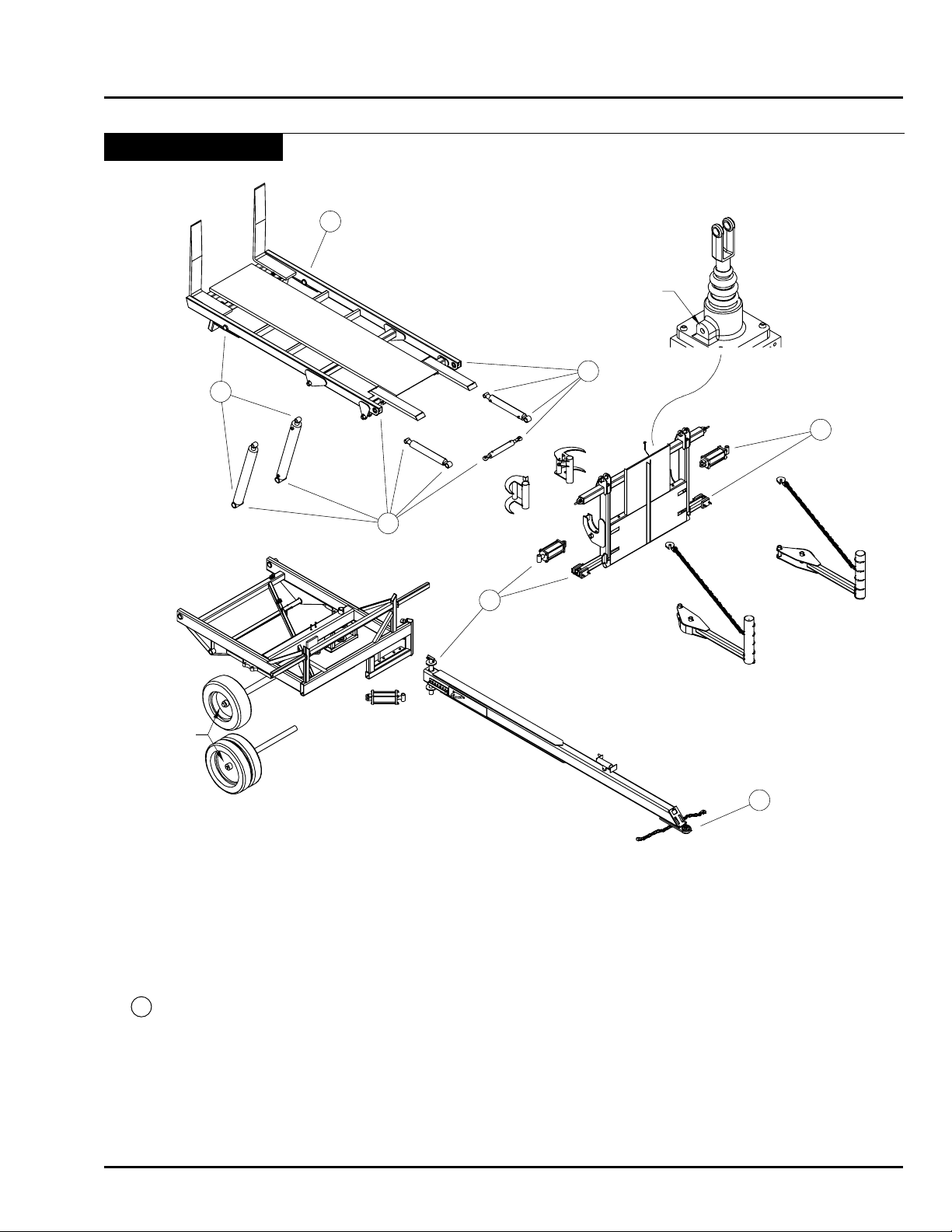
10
10
10
See Note 4
10
10
10
10
Note 2
Lubrication Points
Maintenance
Notes:
1. Alignment arm pivots and main hitch pin have remote grease hoses.
2. Make sure hubs have oil and the plug is in the hub caps. Changing bearings is dicult and requires large size
tools.
3. Grab hooks have no grease zerks. See grab hook assembly for location of plastic bushings.
4. Lubricate Dynex Valve monthly with oil (90W, 10W30, etc.) through plug in spool cap.
5. 10 = 10 hour grease point.
Lubricants
Hydraulic oil ....................................................High quality that meets or exceeds tractor specications
Axle hub oil .................................................................................................................... 80-90 gear lube
Grease ............................................................................................................................ Non clay based
Bale slide surface ..................................................................... Dry lm graphite lubricant (Slip-Plate®)
HD4SR & 12SR June 2015 6-11
Page 64
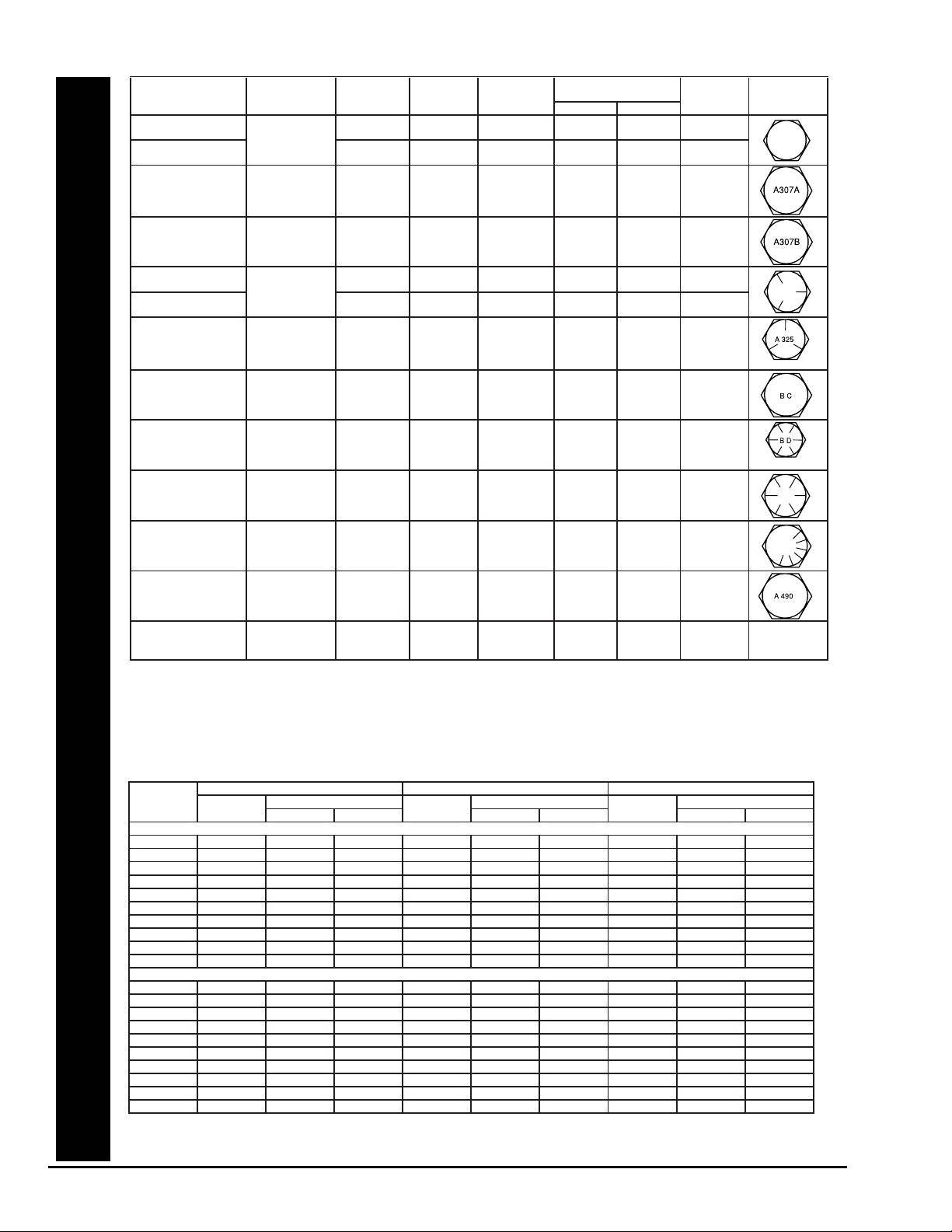
Mechanical Specifications for Externally Threaded Fasteners with Grade Markings
Specification Material Size
Range
Min. Proof
Strength
Min. Tensile
Strength
Core Hardness
Rockwell
Min. Yield
Strength
(in.) (psi) (psi) Min. Max. (psi)
Grade
Identification
Marking
SAE J429-Grade 1 Low or medium
carbon
1/4 - 1 1/2 33,000 60,000 B70 B100 36,000
SAE J429-Grade 2 steel 1/4 - 3/4
7/8 - 1 1/2
55,000
33,000
74,000
60,000
B80
B70
B100
B100
57,000
36,000
ASTM A307-Grade A Low or medium 1/4 - 4 60,000 B69 B100
carbon
See Note 1
steel
ASTM A307-Grade B Low or medium
carbon steel
1/4 - 4 60,000(min)
100,000(max)
B69
See Note 1
B95
SAE J429-Grade 5 Medium carbon 1/4 - 1 85,000 120,000 C25 C34 92,000
ASTM A449-Type1 steel: quenched 1 1/8 - 1 1/2 74,000 105,000 C19 C30 81,000
ASTM A449-Type 1
See Note 2
& tempered 1 3/4 - 3 55,000 90,000 58,000
ASTM A325-Type 1 Medium carbon 1/2 - 1" 85,000 120,000 C25 C34 92,000
steel: quenched 1 1/8 - 1 1/2 74,000 105,000 C19 C30 81,000
& tempered
See Note 3
See Note 5
ASTM A354
Grade BC
Medium carbon
alloy steel:
quenched &
tempered
1/4 - 2 1/2
2 1/2 - 4
105,000
95,000
125,000
115,000
C26
C22
See Note 2
C36
C33
109,000
99,000
ASTM A354 Medium carbon 1/4 - 2 1/2 120,000 150,000 C33 C39 130,000
Grade BD alloy steel: 2 1/2 - 4 105,000 140,000 C31 C39 115,000
quenched &
See Note 2
tempered
See Note 4
SAE J429-Grade 8 Medium carbon
alloy steel:
1/4 - 1 1/2 120,000 150,000 C33 C39 130,000
quenched &
tempered
SAE J429-Grade 8.2 Low carbon
boron steel:
quenched &
tempered
1/4 - 1 120,000 150,000 C33 C39 130,000
ASTM A490-Type 1 Medium carbon
alloy steel:
1/2 - 1 1/2 120,000 150,000(min)
170,000(max)
C33
See Note 3
C38 130,000
quenched &
tempered
ASTM A574 Socket
Head Cap Screw
Low alloy steel:
quenched &
tempered
#0 - 1/2
over 1/2 - 2
140,000
135,000
180,000
170,000
C39
C37
C45
C45
162,000
153,000
Note 1: No minimum hardness is required on bolts and studs 3 x diameter and longer.
Note 2: Bolts less than 3 diameter in length and studs less than 4 diameter in length shall have hardness values not less than minimum and not
more than maximum. This hardness testing is the only mechanical testing requirement for these bolts and studs.
Note 3: Bolts less than 3 x diameter are subject only to maximum/minimum hardness testing.
Note 4: ASTM A354-Grade BD with diameters ¼” thru 2 ½” shall be marked with six radial lines and, in addition may be marked with the grade
symbol “BD.” BD shall be marked on bolts over 2 ½” in diameter.
Note 5: Bolts shall be marked “A325.” Additionally, the bolts may be marked with 3 radial 120 degrees apart (as shown).
Torque-Tension Relationships for SAE J429 Grade Bolts
SAE J429 Grade 2 SAE J429 Grade 5 SAE J429 Grade 8
Tightening Torque Tightening Torque Tightening Torque
Nominal
Thread
Size
Clamp
Load (lbs)
K = .15 K = .20
Clamp
Load (lbs)
K = .15 K = .20
Clamp
Load (lbs)
K = .15 K = .20
Unified Coarse Thread Series
1/4-20 1,300 49 in-lbs 65 in-lbs 2,000 75 in-lbs 100 in-lbs 2,850 107 in-lbs 143 in-lbs
5/16-18 2,150 101 134 3,350 157 210 4700 220 305
3/8-16 3,200 15 ft-lbs 20 ft-lbs 4,950 23 ft-lbs 31 ft-lbs 6,950 32.5 ft-lbs 44 ft-lbs
7/16-14 4,400 24 30 6,800 37 50 9,600 53 70
1/2-13 5,850 36.5 49 9,050 57 75 12,800 80 107
9/16-12 7,500 53 70 11,600 82 109 16,400 115 154
5/8-11 9,300 73 97 14,500 113 151 20,300 159 211
3/4-10 13,800 129 173 21,300 200 266 30,100 282 376
7/8-9 11,425 125 166 29,435 321 430 41,550 454 606
1-8 15,000 187.5 250 38,600 482.5 640 54,540 680 900
Unified Fine Thread Series
1/4-28 1,500 55 in-lbs 75 in-lbs 2,300 85 in-lbs 115 in-lbs 3,250 120 in-lbs 163 in-lbs
5/16-24 2,400 112 150 3,700 173 230 5,200 245 325
3/8-24 3,600 17 ft-lbs 22.5 ft-lbs 5,600 26 ft-lbs 35 ft-lbs 7,900 37 ft-lbs 50 ft-lbs
7/16-20 4,900 27 36 7,550 42 55 10,700 59 78
1/2-20 6,600 41 55 10,200 64 85 14,400 90 120
9/16-18 8,400 59 79 13,000 92 122 18,300 129 172
5/8-18 10,600 83 110 16,300 128 170 23,000 180 240
3/4-16 15,400 144 193 23,800 223 298 33,600 315 420
7/8-14 12,610 138 184 32,480 355 473 45,855 500 668
1-12 16,410 205 273 42,270 528 704 59,670 745 995
Clamp load estimated as 75% of proof load for specified bolts.
Torque values for ¼ and 5/16 inch series are in inch-pounds. All other torque values are in foot-pounds.
Torque values calculated from formula T = KDF where: K=0.15 for “lubricated” conditions K=0.20 for “dry” conditions
Bolt Torque Specication Chart
6-12 June 2015 HD4SR & 12SR
Page 65

Maintenance
Year End Maintenance
Storage
• Park Bale Skoop on level ground.
• Lock hitch in the “in-line” position with hitch safety pin.
• Set loader on the hitch.
• Relieve pressure in lines to prevent “thermal” lock.
WARNING: Keep children away from the stored Bale Skoop. Many of the surfaces on the
machine are slippery and injuries may result from climbing on or around machine.
CAUTION: Keep livestock away from machine so they will not injure themselves or damage
the machine.
Preventative Maintenance
• Paint bed with a graphite impregnated paint (Slip Plate®) to keep it from rusting.
• Touch up any scratches or aking paint.
• Grease all zerks with an all-purpose, non-clay based grease. The non-clay based grease should help eliminate
the plugging of grease zerks.
• Cover tires to prevent sun damage.
CAUTION: Direct sunlight will cause tires and hoses to deteriorate more quickly.
HD4SR & 12SR June 2015 6-13
Page 66

Maintenance
Notes
6-14 June 2015 HD4SR & 12SR
Page 67

Section 7: Storage
Storage
Section 7:
Storage 7-1
Section Contents
Preparing for Storage .......................................................................................................7-2
Cylinder Shaft Protection .................................................................................................7-3
Removing from Storage ....................................................................................................7-3
HD4SR & 12SR June 2015 7-1
Page 68
Storage
Preparing for Storage
• To insure longer life and satisfactory operation,
store the implement in a shed.
• If building storage is impossible, store away from
areas of main activity on level, rm, dry ground.
• Lock hitch in the “in-line” position with hitch safety
pin.
• Set loader on the hitch.
• Relieve pressure in lines to prevent “thermal” lock.
• Clean machine thoroughly.
• Inspect all parts for wear or damage.
• Avoid delays - if parts are required, order at the end
of the season.
• Lubricate grease ttings. (Refer to Maintenance
Section).
• Tighten all bolts to proper specications (Refer to
Maintenance Section).
• For a safer storage, lower the implement into eld
position and release the hydraulic pressure.
• Level implement using hitch jack and block up.
• Relieve pressure from hydraulic system.
• Raise frames, block up and relieve weight from the
tires.
• Cover tires with canvas to protect them from the
elements when stored outside.
• Coat exposed cylinder shafts (Refer to Cylinder
Shaft Protection).
• Paint bed with a graphite impregnated paint (Slip
Plate®) to keep it from rusting.
• Touch up any scratches or aking paint.
Note: Direct sunlight will cause tires and hoses to
deteriorate more quickly.
Warning
Do not allow children to play
on or around the machine.
Caution
Keep livestock away from machine so they
will not injure themselves or damage the
machine.
7-2 June 2015 HD4SR & 12SR
Page 69
Cylinder Shaft Protection
The steps summarized below should be followed when
protecting chrome plated shafting on equipment:
• Position the equipment as it will be stored, and
identify all the exposed portions of the chrome plated
shafts.
• Clean dirt and dust from the exposed portions of
the shaft using a dry cloth or a cloth which has been
dampened with an appropriate solvent.
• Prepare a mixture of 60% oil-based rust inhibitor and
40% Kerosene. Apply a thin coating of this mixture
to the exposed surfaces of the chrome plated shaft.
No. 1 fuel oil may be substituted for Kerosene. A
cloth dipped in the mixture can be used to apply the
coating.
• Inspect the shaft surfaces after six months and apply
additional corrosion preventative mixture.
• If the equipment is to be moved and then stored
again for an extended period of time, the steps above
should be repeated for all shafts that were stroked
during the move.
• Before retracting the cylinders the protective
coating should be removed. This will prevent
fine sand and dirt that has accumulated in the
coating, from damaging the shaft seal. Under
no circumstances should sandpaper or other
abrasive material be used to clean the surfaces.
Plastic or copper wool in combination with an
appropriate solvent will remove most of the dirt.
Storage
Caution
Dirt in the hydraulic system could damage
O-rings, causing leakage, pressure loss and
total system failure.
Removing from Storage
• Review Operator’s Manual.
• Check tire pressure (Refer to Tire Pressure List).
• Clean machine thoroughly. Remove coating from
exposed cylinder shafts (Refer to Cylinder Shaft
Protection).
• Lubricate grease fittings (Refer to Lubricating
Section).
• Tighten all bolts to proper specications (Refer to
Bolt Torque Chart).
HD4SR & 12SR June 2015 7-3
Page 70

Storage
Notes
7-4 June 2015 HD4SR & 12SR
Page 71

Section 8: Troubleshooting
Troubleshooting
Section 8:
Troubleshooting 8-1
Section Contents
Troubleshooting Guide ......................................................................................................8-2
Hydraulic System Overview .......................................................................................8-2
Troubleshooting the Hydraulics ..................................................................................8-2
Valves and Valve Functions ........................................................................................8-2
12SR Models Only .....................................................................................................8-2
Hydraulic Troubleshooting Chart .......................................................................................8-3
Loader will not raise ...................................................................................................8-3
Loader raises slow .....................................................................................................8-3
Loader lowers when alignment arms are opening ......................................................8-3
Loader lowers before alignment arm open .................................................................8-3
Loader will not lower ...................................................................................................8-3
Loader lowers slow .....................................................................................................8-3
Alignment Arms do not center bales, or squeeze bales tight ..................................8-3
Alignment Arms open as loader raises, and close as loader lowers ........................8-3
Grab Hooks push bale away from loader ...................................................................8-3
Grab Hooks will not engage .......................................................................................8-3
Grab Hooks will not disengage ...................................................................................8-3
Grab Hooks engage before alignment arms ...............................................................8-3
Grab Hooks engage when loader raises, and retract when loader lowers .................8-3
HD4SR & 12SR June 2015 8-1
Page 72
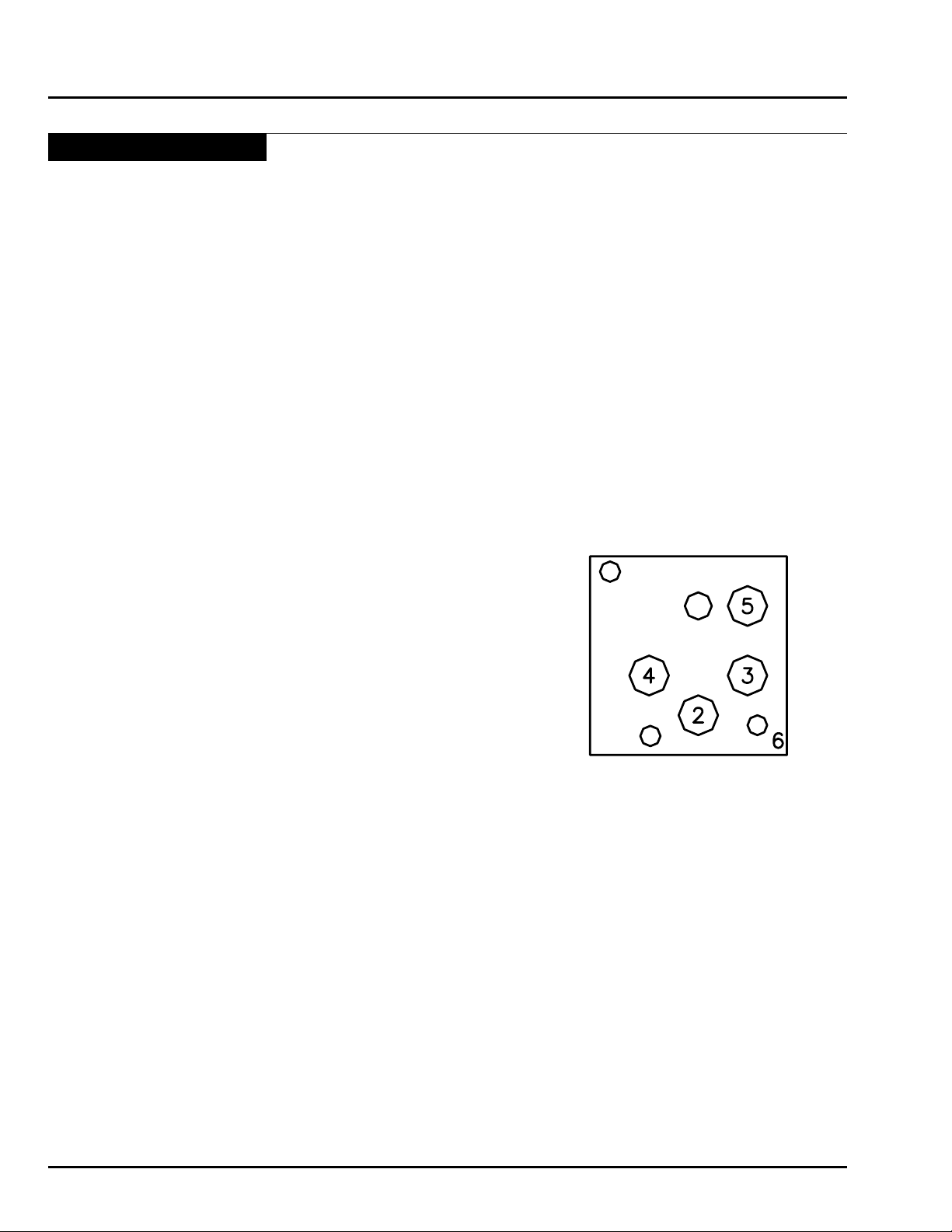
Manifold Valve
Troubleshooting
Troubleshooting Guide
Hydraulic System Overview
The movement of the loader on the Auto Align Bale Skoop is controlled by the Manifold Valve located under the
Bed. The Manifold consists of 5 pressure relief valves which are set to open when the uid pressure against them
reaches a designated pressure. These internal pressure relief valves are adjustable, allowing for ne-tuning of the
hydraulically actuated sequence of motions of the loader.
Troubleshooting the Hydraulics
The hydraulic systems for the Bale Skoop are fairly simple. Most problems are rooted either in mis-adjusted pressure
relief valve(s) in the manifold, or switched hoses entering the manifold.
When troubleshooting hydraulic problems always start with hose routing. Use the Hydraulic Hose Routing diagram
in the “Parts Breakdown” section to conrm the proper hose routing.
If hoses are properly routed, adjusting the pressure relief valves in the manifold should resolve the problem.
Use the Troubleshooting Chart on the next page to correlate the problem with a potential solution.
Valves and Valve Functions
Valve 2. Plug.
Valve 3. Sequence check valve causes the alignment arms to close rst
and then the loader to raise.
Valve 4. Counter balance valve which holds the loader up while the alignment
arms open.
Valve 5. Sequence valve which allows the alignment arms to close rst
before the grab hooks engage.
Valve 6. Check valve which causes the oil to ow in the right direction.
12SR Models Only
Grab Hook Valve
4-Way valve used to direct the ow of oil to the grab hook cylinder.
8-2 June 2015 HD4SR & 12SR
Page 73

Hydraulic Troubleshooting Chart
Troubleshooting
Symptom Problem
Loader will not raise
Loader raises slow
Loader lowers when alignment arms are opening
Loader lowers before alignment arm open
Loader will not lower
Loader lowers slow
Alignment Arms do not center bales, or squeeze bales tight
Alignment Arms open as loader raises, and close as loader lowers
Valve #3 is set too high
Valve #3 is set too high
Tractor hydraulic ow or
pressure is slow or low
Valve #4 is set too low
Valve #4 is set too low
Valve #4 set too high
Valve #4 set too high
Valve #3 set too low
Wrong hose routing
Solution
Turn adjustment screw OUT on valve #3
Turn adjustment screw OUT on valve #3
Contact tractor manufacturer or dealer
Turn adjustment screw OUT on valve #4
Turn adjustment screw OUT on valve #4
Turn adjustment screw IN on valve #4
Turn adjustment screw IN on valve #4
Turn adjustment screw IN on valve #3
Check hose routing against diagram
Grab Hooks push bale away from loader
Grab Hooks will not engage
Grab Hooks will not disengage
Grab Hooks engage before alignment arms
Grab Hooks engage when loader raises, and retract when loader lowers
Valve #3 set too low
Valve #5 set too low
Wrong hose routing
Spool on 4-Way Valve is not
retracting
Valve #5 set too high
Spool on 4-Way Valve is not
being extended
Hoses are connected wrong
Valve #5 set too high
Valve #5 set too low
Wrong hose routing
Turn adjustment screw IN on valve #3
Turn adjustment screw IN on valve #5
Check hose routing against diagram
Check 4-Way Valve assembly for kinks in spring
or cable when loader is lowered
Turn adjustment screw OUT on valve #5
Check 4-Way Valve assembly and pull spring and
cable hook-up for failure or malfunction
Switch 4-Way Valve hoses at Manifold.
Turn adjustment screw OUT on valve #5
Turn adjustment screw IN on valve #5
Check hoses routing against diagram
If you continue to have problems please contact an authorized ProAG dealer.
HD4SR & 12SR June 2015 8-3
Page 74

Troubleshooting
Notes
8-4 June 2015 HD4SR & 12SR
Page 75

Section 9: Parts Breakdown
Parts Breakdown
Section 9:
Parts Breakdown 9-1
Section Contents
Bale Skoop Final Assembly .................................................................9-2
Loader Assembly .................................................................................9-4
12SR - Grab Hook Assembly - 2014 to Present ...................................9-6
HD4SR - Short Alignment Arm Assembly ............................................9-8
12SR - Medium Alignment Arm Assembly ...........................................9-9
Bed Assembly ...................................................................................9-10
Frame Assembly ................................................................................9-12
Bed Rest Assembly ...........................................................................9-14
Hitch Assembly ..................................................................................9-16
Implement Tire and Axle Assembly - Prior to 2015 ............................9-18
Truck Tire and Axle Assembly - Prior to 2015 .....................................9-20
Terra Tire and Axle Assembly - Prior to 2015 .....................................9-22
Terra Tire and Axle Assembly - 2015 to Present .................................9-24
HD4SR Hydraulic Hose Schematic ...................................................9-26
12SR Hydraulic Hose Schematic - 2015 to Present ..........................9-28
12SR Hydraulic Hose Schematic - 2014 to 2015 ...............................9-30
12SR Hydraulic Hose Schematic - 2004 to 2014 ...............................9-32
Cylinder Specification Sheet .............................................................9-34
Electrical Warning Assembly .............................................................9-36
Electrical Assembly ...........................................................................9-37
HD4SR & 12SR October 2015 9-1
Page 76
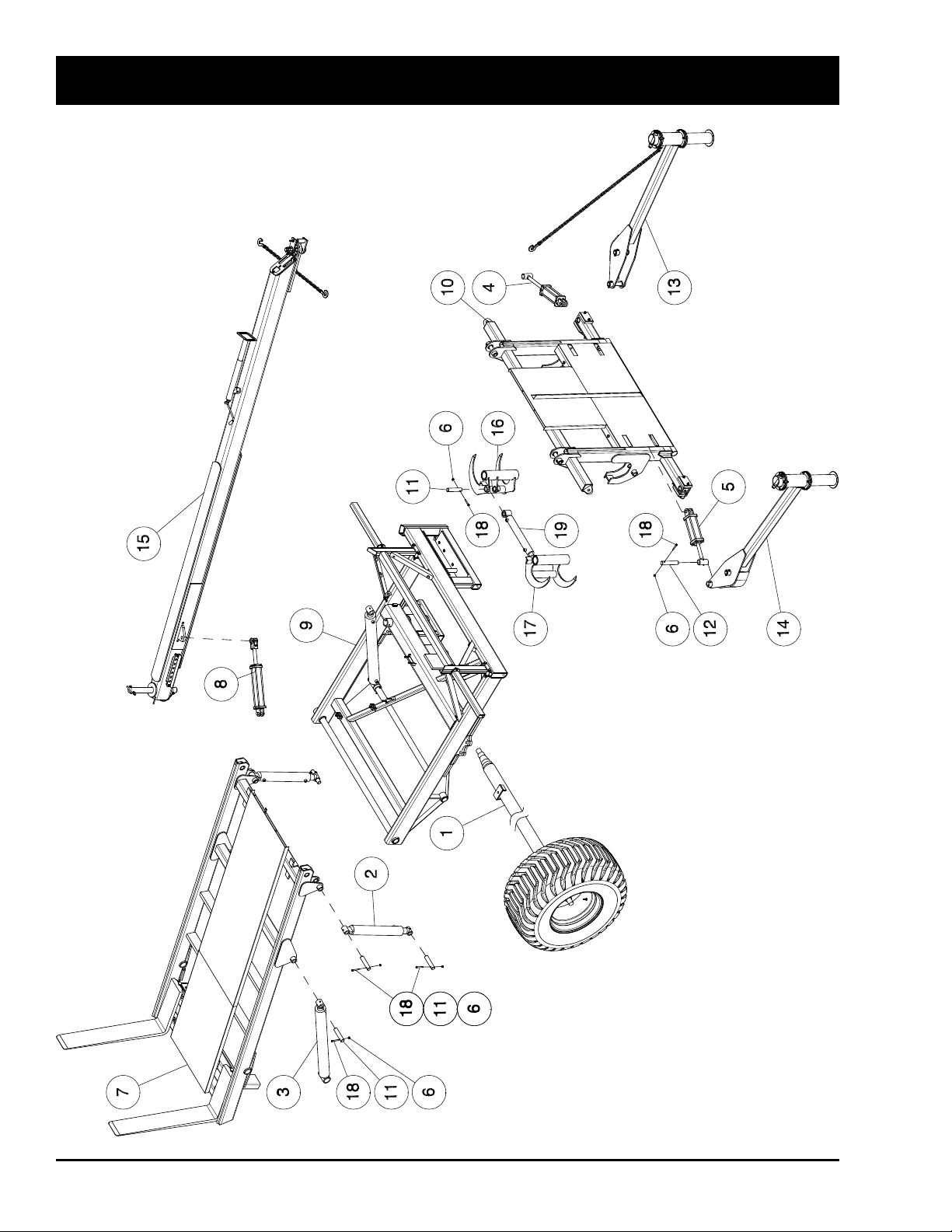
HD4SR and 12SR
Bale Skoop Final Assembly
9-2 October 2015 HD4SR & 12SR
Page 77

Bale Skoop Final Assembly
Item Part No. Description Qty
1 10410 Terra Axle Assembly ........................................................................................................ 1
10385 Truck Axle Assembly ........................................................................................................ 1
2 10032 Loader Cylinder - 3 1/2 x 20 Stroke ................................................................................. 2
3 10033 Bed Cylinder - 4 x 36 Stroke ............................................................................................ 2
4 10034 LH Alignment Cylinder - 3 1/4 x 8 Stroke ......................................................................... 1
5 10035 RH Alignment Cylinder - 12SR - 3 1/2 x 8 Stroke ............................................................ 1
6 10302 Nylon Insert Locknut - 7/16 ............................................................................................. 14
7 12290 Bed ................................................................................................................................... 1
*10048 SR Model Bed .................................................................................................................. 1
8 12302 Hitch Cylinder - 3 x 14 Stroke .......................................................................................... 1
9 12474 Main Frame ...................................................................................................................... 1
*10131 Main Frame ...................................................................................................................... 1
10 K44274 Loader - HD4SR .............................................................................................................. 1
12494 Loader - 12SR ................................................................................................................. 1
*10214 Basic Loader Assembly ................................................................................................... 1
11 12519 Pin - Bed Cylinder - 1 1/2 Dia x 6 UL ............................................................................... 10
*10256 Pin - Bed Cylinder - 1 7/16 Dia x 7 UL
12 12520 Pin - Alignment Arm - 1 1/2 Dia x 7 1/4 UL ...................................................................... 4
13 12525 LH Medium Alignment Arm Assembly - 12SR ................................................................. 1
*10405 LH Medium Alignment Arm Assembly - 12SR ................................................................. 1
12527 LH Short Alignment Arm - HD4SR ................................................................................... 1
*10406 LH Short Alignment Arm - HD4SR ................................................................................... 1
14 12526 RH Medium Alignment Arm Assembly - 12SR ................................................................. 1
*10404 RH Medium Alignment Arm Assembly - 12SR ................................................................. 1
12528 RH Short Alignment Arm - HD4SR .................................................................................. 1
*10011 RH Short Alignment Arm - HD4SR .................................................................................. 1
15 K42480 Hitch Beam Assembly ...................................................................................................... 1
*10393 Hitch Assembly ................................................................................................................ 1
16 12532 Grab Hook - Left - 12SR .................................................................................................. 1
17 12533 Grab Hook - Right - 12SR ................................................................................................ 1
18 10847 Hex Bolt - 7/16 x 3 Lg GR8 .............................................................................................. 14
19 K42468 Cylinder Assembly W/Bushings - 2 1/2 x 16 Stroke ......................................................... 1
12166 Grab Hook Cylinder 03 - 12SR ........................................................................................ 1
12039 Grommet - Inserts Into Light Bar (Not Shown)................................................................. 2
10248 Slip Coat .......................................................................................................................... 1
W-4647 Red Paint ......................................................................................................................... 1
10359 Warning Light Assembly .................................................................................................. 1
K34987 Operators Manual - HD4SR and 12SR ............................................................................ 1
K34990 Assembly Manual - HD4SR and 12SR ............................................................................ 1
* Prior to serial # SR12060881 for the 12SR & SR40600866 for the HD4SR
HD4SR & 12SR October 2015 9-3
Page 78
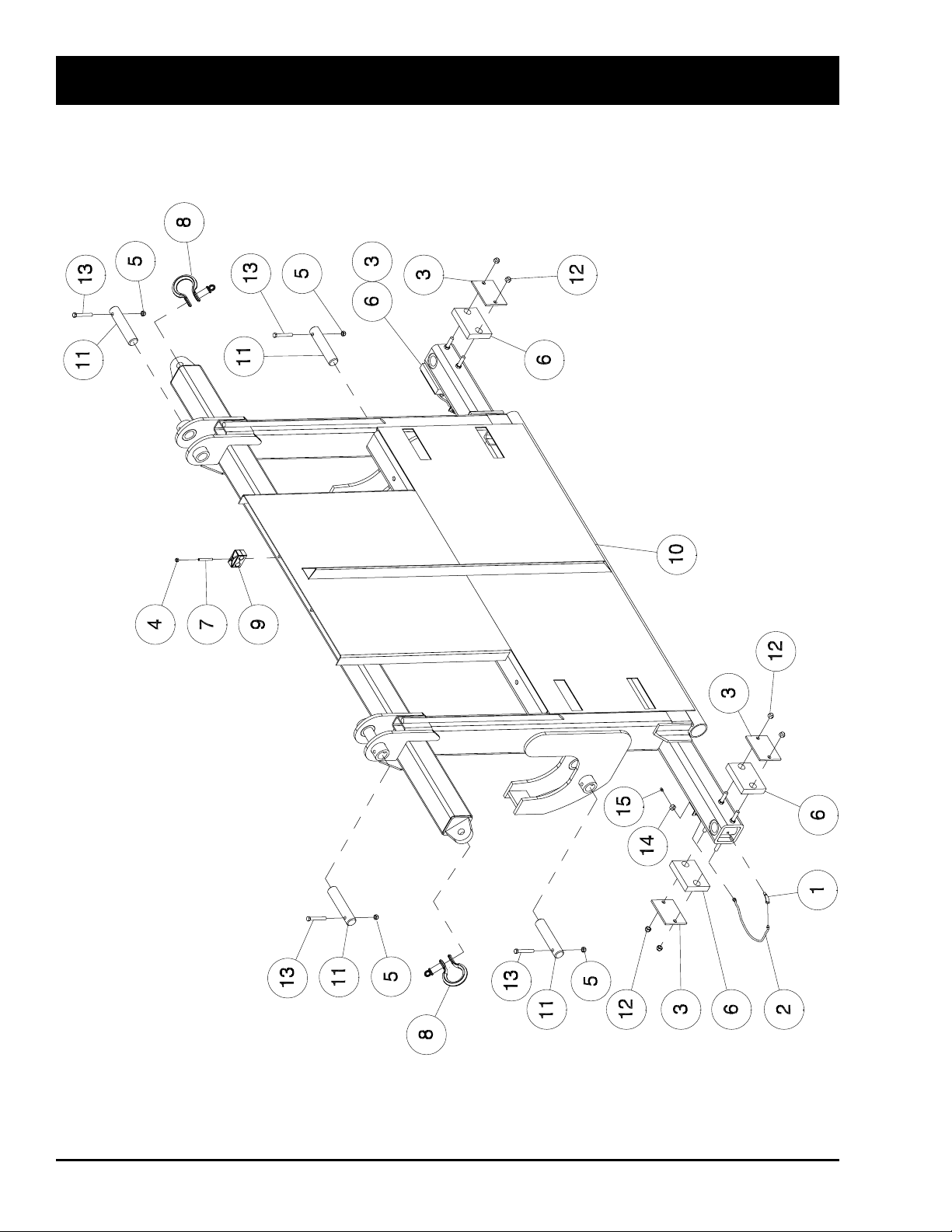
HD4SR and 12SR
Loader Assembly
9-4 October 2015 HD4SR & 12SR
Page 79

Loader Assembly
Item Part No. Description Qty
1 10173 Street Grease Elbow - NPTF 45 ..................................................................................... 2
2 10183 Remote Grease Hose - 1/8 x 12 Lg ................................................................................. 2
3 10104 Plate - Alignment Slider ................................................................................................... 4
4 10231 Locknut - 5/16 Nylon Insert ............................................................................................. 3
5 10302 Locknut - 7/16 Nylon Insert ............................................................................................. 4
6 10351 Slider - Alignment Arm ..................................................................................................... 4
7 10811 Set Screw - 5/16 x 2 1/2 Lg .............................................................................................. 3
8 10827 Round Pin Shackle - 3/4 .................................................................................................. 2
9 11740 Plastic Hose Clamps - 13/16 ............................................................................................ 3
10 K44274 Loader - HD4SR (Not Shown) ......................................................................................... 1
12494 Loader - 12SR ................................................................................................................. 1
*10193 Loader .............................................................................................................................. 1
11 12519 Pin - Bed Cylinder - 1 1/2 x 7 ........................................................................................... 4
*10256 Pin - 1 7/16 x 7 ................................................................................................................. 4
12 F-3405 Locknut - 1/2 Nylon Insert ............................................................................................... 8
13 10847 Hex Bolt - 7/16 x 3 Lg GR8 .............................................................................................. 4
14 10227 3/8 - Grease Hose Jam Nut ............................................................................................. 2
15 S-752 Grease Fitting - 1/4 .......................................................................................................... 2
* Prior To Serial # SR12060881 For The 12SR & SR40600866 For The HD4SR
HD4SR & 12SR October 2015 9-5
Page 80
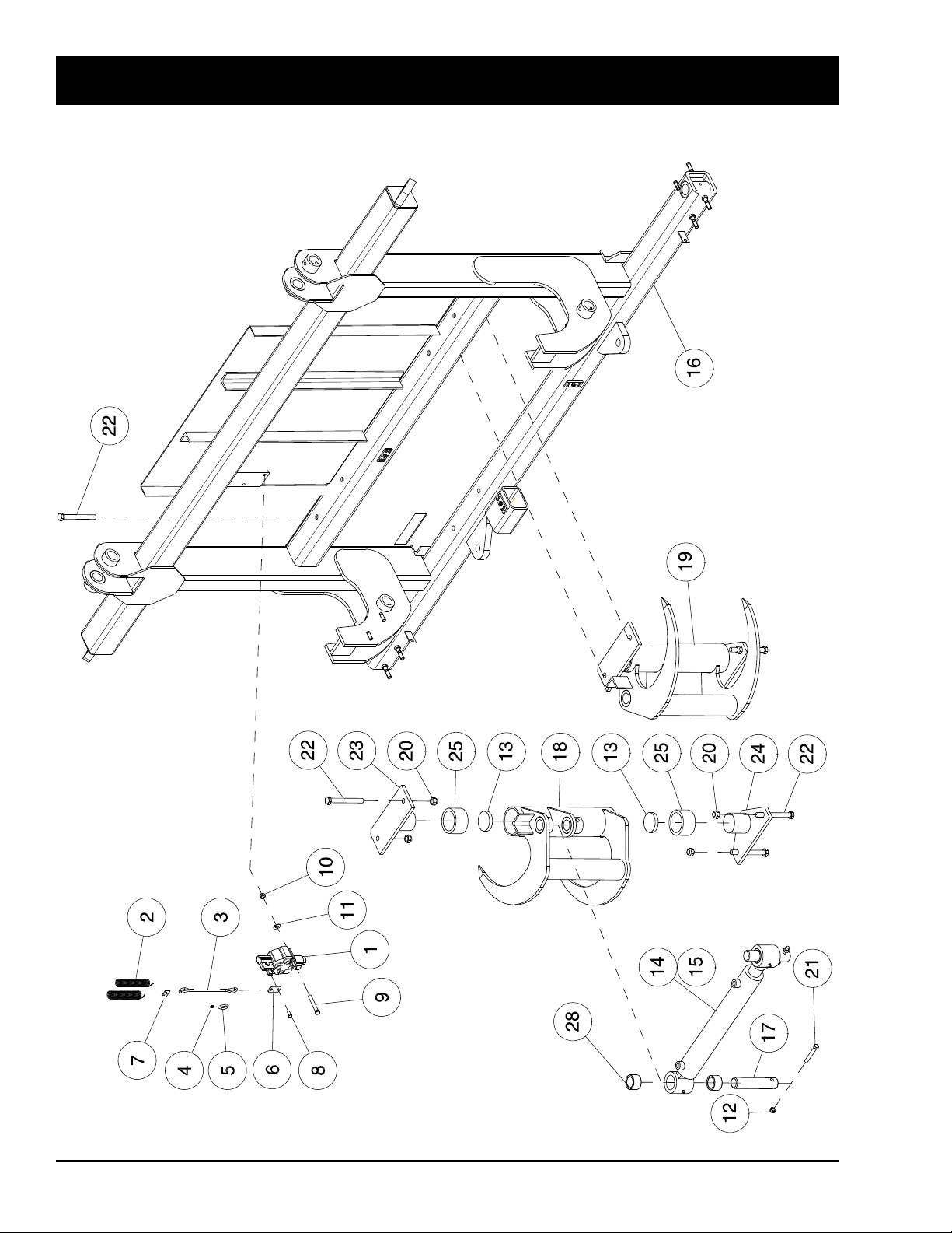
12SR - Grab Hook Assembly - 2014 to Present
For Serial Number - SR12143100 and Up
HD4SR and 12SR
9-6 October 2015 HD4SR & 12SR
Page 81

12SR - Grab Hook Assembly - 2014 to Present
Item Part No. Description Qty
1 K53973 Directional Valve............................................................................................................... 1
2 10845 Spring - 3/4 x 5 3/4........................................................................................................... 2
3 K53993 Pull Cable ......................................................................................................................... 1
4 K42389 Oval Sleeve - 0.062 Diameter .......................................................................................... 4
5 K42390 Thimble ............................................................................................................................ 2
6 K53980 Plate - Valve Link.............................................................................................................. 1
7 K53987 Plate - Spring Link............................................................................................................ 1
8 K53981 Hex Bolt - M8 x 25 mm Lg................................................................................................ 1
9 S-1302 Hex Bolt - 5/16 x 2 1/2 Lg ................................................................................................ 2
10 W-513 Hex Nut - 5/16 .................................................................................................................. 2
11 W-522 Lockwasher - 5/16 ............................................................................................................ 2
12 10302 Locknut - 7/16 Nylon Insert .............................................................................................. 2
13 10355 Grab Hook Thrust Bearing ............................................................................................... 4
14 12166 Hydraulic Cylinder - 2 1/2 x 16 Stroke.............................................................................. 1
15 K42468 Cylinder Assembly W/Bushings - 2 1/2 x 16 Stroke ......................................................... 1
16 12494 Loader - 12SR ................................................................................................................. 1
17 12519 Pin - Bed Cylinder - 1 1/2 x 7 .......................................................................................... 2
18 12532 LH Grab Hook .................................................................................................................. 1
19 12533 RH Grab Hook ................................................................................................................. 1
20 10230 Locknut - 5/8 Nylon Insert ............................................................................................... 8
21 D-5251 Hex Bolt - 7/16 x 3 Lg ...................................................................................................... 2
22 10065 Hex Bolt - 5/8 x 5 1/2 Lg GR8 .......................................................................................... 8
23 K42393 Upper Grab Hook Pivot .................................................................................................... 2
24 K42394 Lower Grab Hook Pivot .................................................................................................... 2
25 K42396 Grab Hook Bushing .......................................................................................................... 4
26 K44008 Bushing - Cylinder Pivot ................................................................................................... 4
HD4SR & 12SR October 2015 9-7
Page 82
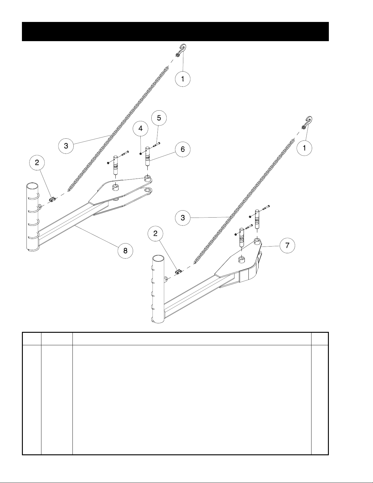
HD4SR
HD4SR - Short Alignment Arm Assembly
Item Part No. Description Qty
1 10662 3/8 Chain Locking Grab Hook .......................................................................................... 2
2 10677 7/16 - 1/2 Twin Clevis ....................................................................................................... 2
3 10750 Chain - 75 Lg - Grade 70 (Includes Item 1) ..................................................................... 2
4 10302 Locknut - 7/16 Nylon Insert ............................................................................................. 4
5 D-5251 Hex Bolt - 7/16 x 3 .......................................................................................................... 4
6 12520 Pin - 1 1/2 x 8 1/4 ............................................................................................................. 4
*10257 Pin - 1 7/16 x 8 1/4 ........................................................................................................... 4
7 12527 LH Short Alignment Arm .................................................................................................. 1
*10406 LH Short Alignment Arm .................................................................................................. 1
8 12528 RH Short Alignment Arm ................................................................................................. 1
*10011 RH Short Alignment Arm ................................................................................................. 1
* Prior To Serial # SR40600866 For The HD4SR
9-8 October 2015 HD4SR & 12SR
Page 83
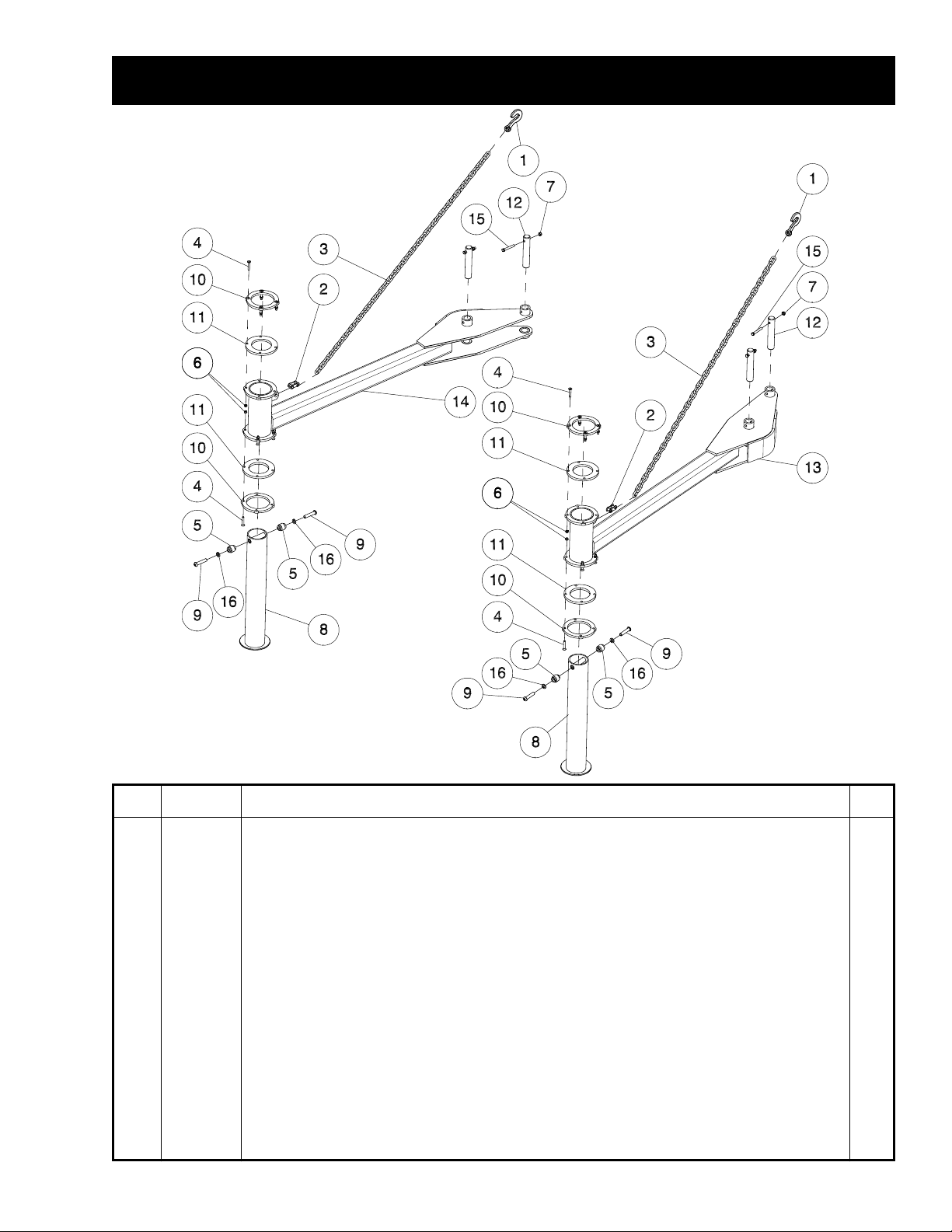
HD12SR
12SR - Medium Alignment Arm Assembly
Item Part No. Description Qty
1 10662 Chain Locking Grab Hook - 3/8 ...................................................................................................... 2
2 10677 Twin Clevis - 7/16 x 1/2 ................................................................................................................... 2
3 10750 Chain - 75 Lg - Grade 70 (Includes Item 1) ................................................................................... 2
4 10074 Cap Screw - 3/8 x 2 1/4 .................................................................................................................. 16
5 10076 Rubber Roller Bushing - 5/8 x 2 ..................................................................................................... 4
6 10229 Nylon Insert Locknut - 3/8 .............................................................................................................. 16
7 10302 Nylon Insert Locknut - 7/16 ............................................................................................................ 4
8 10400 Foot Slider ...................................................................................................................................... 2
9 10835 BH Cap Screw - 5/8 x 3 .................................................................................................................. 4
10 10841 Bearing Plate 99 ............................................................................................................................. 4
11 10846 Foot Slider Bearing 99 .................................................................................................................... 4
12 12520 Pin - 1 1/2 x 8 1/4 ........................................................................................................................... 4
*10257 Pin - 1 7/16 x 8 1/4 ......................................................................................................................... 4
13 12525 LH Medium Alignment Arm ............................................................................................................ 1
*10220 LH Medium Alignment Arm ........................................................................................................... 1
14 12526 RH Medium Alignment Arm ............................................................................................................ 1
*10399 RH Medium Alignment Arm ............................................................................................................ 1
15 10847 Hex Bolt - 7/16 x 3 Lg GR8 ............................................................................................................. 4
16 W-526 Lockwasher - 5/8 ............................................................................................................................ 4
* Prior To Serial # SR12060881 For The 12SR
HD4SR & 12SR October 2015 9-9
Page 84
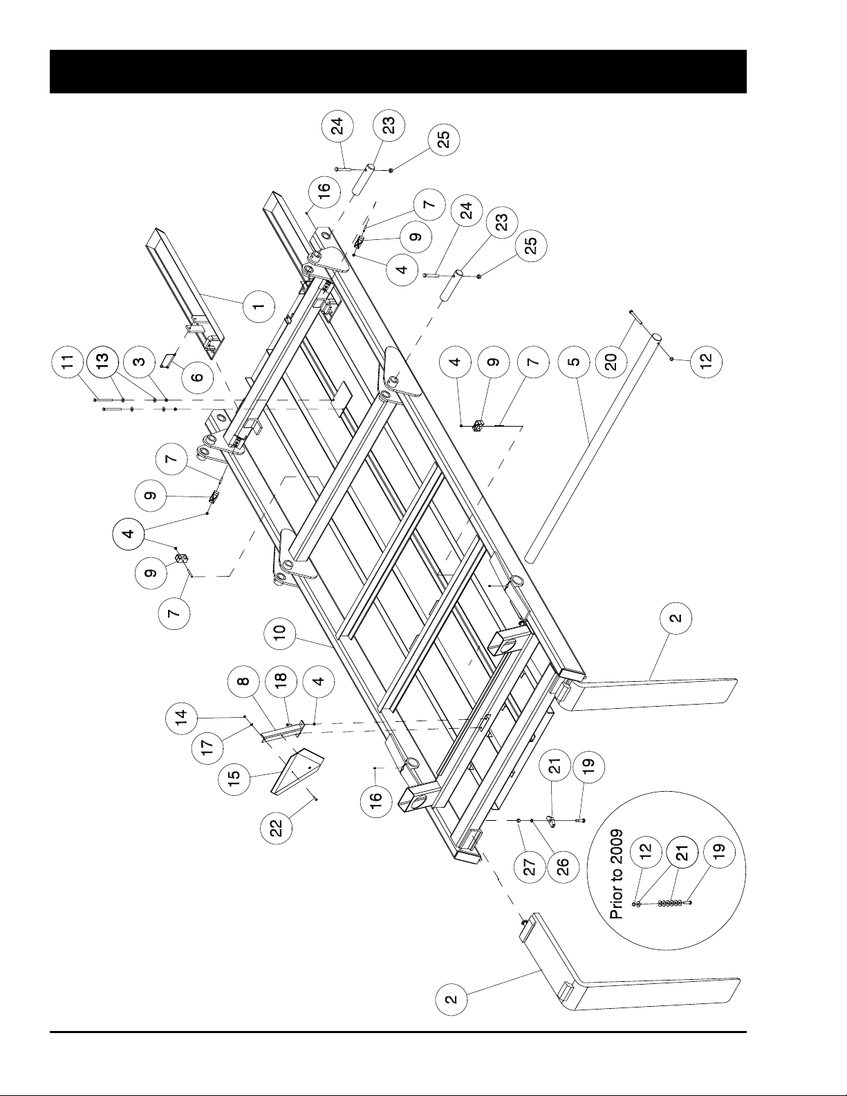
HD4SR and 12SR
Bed Assembly
Note:
Bed is shown Upside Down
for Clarity.
9-10 October 2015 HD4SR & 12SR
Page 85

Bed Assembly
Item Part No. Description Qty
1 10130 Bed Extensions Painted ................................................................................................... 2
2 10163 Forklift Tooth - 8 x 48 ....................................................................................................... 2
3 10229 Locknut - 3/8 Nylon Insert ............................................................................................... 2
4 10231 Locknut - 5/16 Nylon Insert ............................................................................................ 6
5 10260 Bed Pivot Shaft ................................................................................................................ 1
6 10414 Snap Lock Pins - 5/16 x 4 UL .......................................................................................... 2
7 10811 Set Screw - 5/16 x 2 1/2 Lg .............................................................................................. 4
8 11132 Bracket - SMV Sign .......................................................................................................... 1
9 11740 Plastic Hose Clamp - 13/16 ............................................................................................ 4
10 12290 SR Model Bed Weldment ................................................................................................. 1
*10048 SR Model Bed Weldment ................................................................................................. 1
11 10063 Hex Bolt - 3/8 x 5 Lg GR8 ................................................................................................ 2
12 F-3405 Locknut - 1/2 Nylon Insert ............................................................................................... 3
13 W-538 Washer - 13/32 ID x 1 OD x 16 Ga .................................................................................. 4
14 10233 Locknut - 1/4 Nylon Insert ............................................................................................... 2
15 N34475 Slow Moving Vehicle Emblem .......................................................................................... 1
16 S-752 Grease Zerk - 1/4 Straight .............................................................................................. 4
17 S-1198 Washer - 5/16 ID x 3/4 OD x 0.065 .................................................................................. 2
18 W-471 Hex Bolt - 5/16 x 1 Lg ...................................................................................................... 2
19 C33957 Bolt Carriage Head - 3/4 x 3 Lg - 2009 ............................................................................ 2
10070 Hex Bolt - 1/2 x 1 3/4 Lg GR8 - Prior to 2009 .................................................................. 2
20 K25798 Hex Bolt - 1/2 x 4 Lg GR8 ................................................................................................ 1
21 K45683 Fork Retainer Block - 2009 .............................................................................................. 2
W-539 Flatwasher - 1/2 - Prior to 2009 ....................................................................................... 14
22 W-1552 Hex Bolt - 1/4 x 1 Lg ........................................................................................................ 2
23 12519 Pin - Bed Cylinder - 1 1/2 x 7 ........................................................................................... 4
*10256 Pin - 1 7/16 x 7 ................................................................................................................. 4
24 D-5251 Hex Bolt - 7/16 x 3 Lg ...................................................................................................... 4
25 10302 Locknut - 7/16 Nylon Insert ............................................................................................. 4
26 W-527 Lockwasher - 3/4 .............................................................................................................. 2
27 W-518 Hex Nut - 3/4 GR5 ........................................................................................................... 2
* Prior to serial # SR12060881 for the 12SR & SR40600866 for the HD4SR
HD4SR & 12SR October 2015 9-11
Page 86
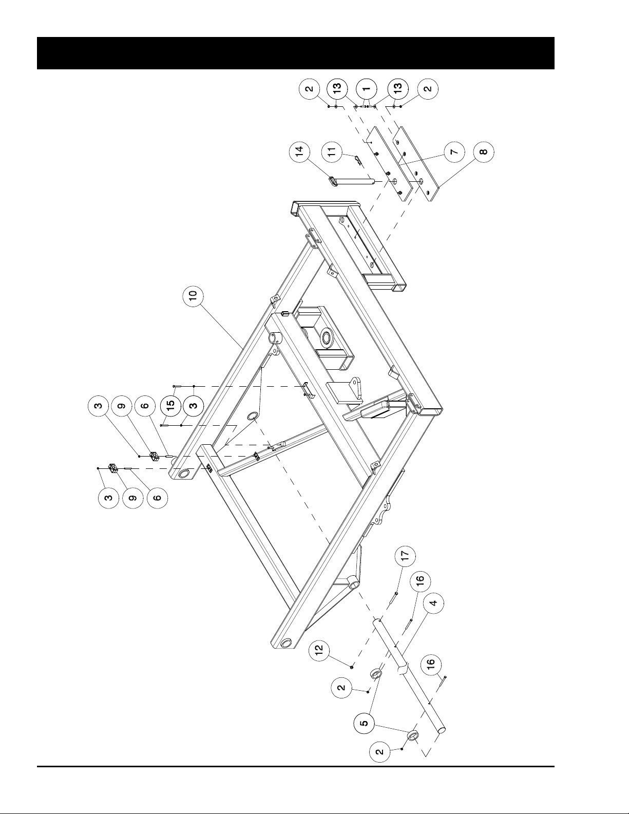
HD4SR and 12SR
Frame Assembly
9-12 October 2015 HD4SR & 12SR
Page 87

Frame Assembly
Item Part No. Description Qty
1 W-477 Bolt Hex Head - 3/8 x 1 /12 Lg ......................................................................................... 8
*10075 3/8 x 1 1/2 GR 8 Low Allen Head Cap Screw .................................................................. 8
2 10229 Nylon Insert Locknut - 3/8 ................................................................................................ 10
3 10231 Nylon Insert Locknut - 5/16 ............................................................................................. 6
4 10258 Hoist Shaft ....................................................................................................................... 1
5 10308 Hoist Spacer - 3 1/4 OD x .375W ..................................................................................... 2
6 10811 Set Screw - 5/16 x 2 1/2 Lg .............................................................................................. 2
7 11123 Slider Pad - Upper............................................................................................................ 1
8 11124 Slider Pad - Lower ............................................................................................................ 1
9 11740 Plastic Hose Clamp Assembly ......................................................................................... 2
10 12474 Main Frame ...................................................................................................................... 1
*10131 Main Frame Weldment ..................................................................................................... 1
11 BW-11 Hairpin - 3/16 ................................................................................................................... 1
12 F-3405 Locknut - 1/2 Nylon Insert ............................................................................................... 2
13 W-538 Washer - 13/32 ID x 1 OD x 16 Ga .................................................................................. 16
14 K42477 Hitch Safety Pin - 1 1/2 x 13 1/2 UL ................................................................................. 1
*10415 Hitch Safety Pin ............................................................................................................... 1
15 S-1302 Hex Bolt - 5/16 x 2 1/2 Lg ................................................................................................ 4
16 10813 Hex Bolt - 3/8 x 3 1/2 Lg GR8 .......................................................................................... 2
17 K25798 Hex Bolt - 1/2 x 4 Lg GR8 ................................................................................................ 2
* Prior To Serial # SR12060881 For The 12SR & SR40600866 For The HD4SR
HD4SR & 12SR October 2015 9-13
Page 88
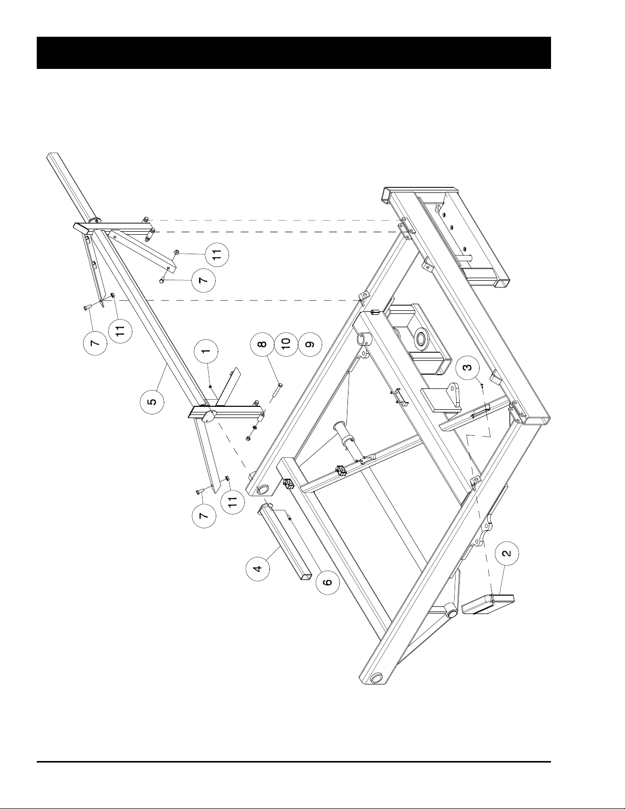
HD4SR and 12SR
Bed Rest Assembly
9-14 October 2015 HD4SR & 12SR
Page 89

Bed Rest
Item Part No. Description Qty
1 10229 Locknut - 3/8 Nylon Insert ................................................................................................ 14
2 10295 Manual Box ...................................................................................................................... 1
3 10297 Screw - 1/4 - 20 x 3/4 ...................................................................................................... 2
4 11129 Light Bar ........................................................................................................................... 2
5 K42475 Frame - Bed Rest ............................................................................................................. 1
6 W-477 Hex Bolt - 3/8 x 1 1/2 Lg .................................................................................................. 4
7 W-497 Hex Bolt - 5/8 x 1 1/2 Lg .................................................................................................. 4
8 W-504 Hex Bolt - 5/8 x 4 Lg ........................................................................................................ 4
9 W-517 Hex Nut - 5/8 .................................................................................................................... 4
10 W-526 Lockwasher - 5/8 .............................................................................................................. 4
11 W14434 Locknut - 5/8 Flange ....................................................................................................... 4
HD4SR & 12SR October 2015 9-15
Page 90
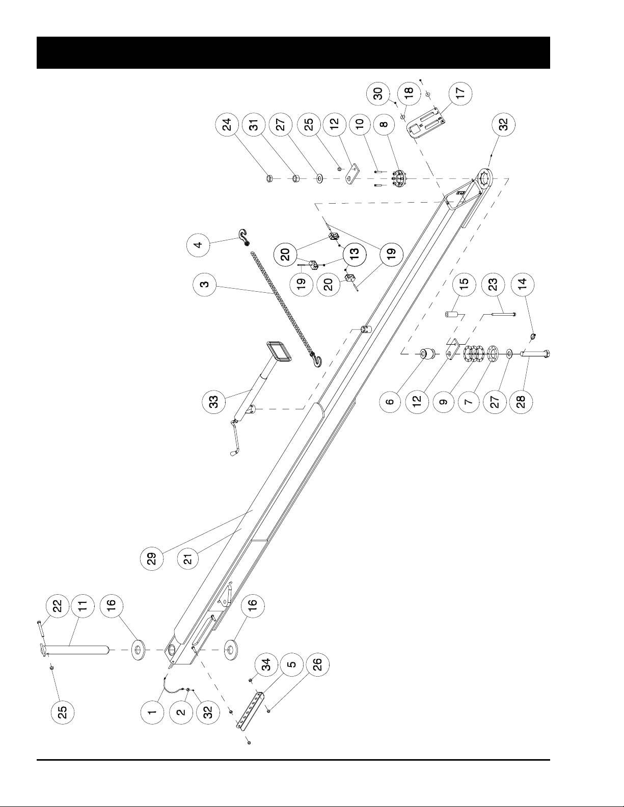
HD4SR and 12SR
Hitch Assembly
9-16 October 2015 HD4SR & 12SR
Page 91

Hitch Assembly
Item Part No. Description Qty
1 10183 Remote Grease Hose - 1/8 x 12 ..................................................................................... 1
2 10227 Grease Hose Jam Nut - 3/8 ............................................................................................. 1
3 10369 Chain - 3/8 x 8 Foot ......................................................................................................... 1
4 10662 3/8 Chain Locking Grab Hook .......................................................................................... 2
5 10025 Hitch Hose Manifold ......................................................................................................... 1
*10019 Hitch Hose Manifold ......................................................................................................... 1
6 10049 Hitch Ball .......................................................................................................................... 1
7 10050 Ring Hitch Lower .............................................................................................................. 1
8 10051 Ring Hitch Upper .............................................................................................................. 1
9 10052 Ball Hitch Shim ................................................................................................................. 3
10 10069 Allen Head Cap Screw Plain - 3/8 x 2 GR 8 ................................................................... 8
11 10129 Pin - Hitch Pivot ............................................................................................................... 1
12 10142 Plate - Draw Bar Hitch...................................................................................................... 2
13 10231 Locknut - 5/16 Nylon Insert ............................................................................................. 3
14 10247 Klik Pin W/Chain & Cotter Pin .......................................................................................... 1
15 10313 Spacer Bushing - 1 1/2 OD x .375W ............................................................................... 1
16 10352 Washer - Hitch Pivot ........................................................................................................ 2
17 10354 End Cap - Hitch ................................................................................................................ 1
18 10364 Washer - 9/32 ID x 1 1/4 OD x 16Ga ............................................................................... 3
19 10811 Set Screw - 5/16 x 2 1/2 Lg .............................................................................................. 3
20 11740 Plastic Hose Clamp Assembly ......................................................................................... 3
21 12529 Hitch Beam ...................................................................................................................... 1
*10199 SR Hitch Painted .............................................................................................................. 1
22 10816 Hex Bolt - 5/8 x 5 Lg GR8 ................................................................................................ 1
23 10066 Hex Bolt - 5/8 x 8 Lg GR8 ................................................................................................ 1
24 C15768 Hex Jam Nut - 1 1/4 ......................................................................................................... 1
25 10230 Locknut - 5/8 Nylon Insert ............................................................................................... 2
26 F-3405 Locknut - 1/2 Nylon Insert ............................................................................................... 2
27 10682 Washer - 1 5/16 ID x 2 3/4 OD x 8 Ga ............................................................................. 2
28 K42469 Hitch Bolt - 1 1/4 x 9 Lg .................................................................................................... 1
29 K42480 Assembly - Hitch Beam W/Ball Clevis .............................................................................. 1
30 10233 Locknut - 1/4 Nylon Insert ................................................................................................ 3
31 P61D20 Hex Nut - 1 1/4 ................................................................................................................. 1
32 S-752 Straight Grease Zerk - 1/4 .............................................................................................. 2
33 S39391 Top Wind Jack - 2000 Lb .................................................................................................. 1
10200 SR Jack ............................................................................................................................ 1
34 W-516 Hex Nut - 1/2 .................................................................................................................... 2
* Prior To Serial # SR12060881 For The 12SR & SR40600866 For The HD4SR
HD4SR & 12SR October 2015 9-17
Page 92
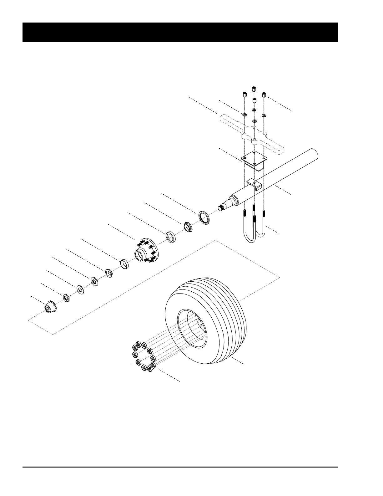
Implement Tire and Axle Assembly - Prior to 2015
1
2
3
4
5
6
7
8
9
10
11
12
13
14
15
16
17
18
NOTE:
1) Axle is mirrored about
centerline. (Except for Left-Hand
lug nuts on left side of machine.)
2) Check maintenance section for
torque specications.
Axle U-Bolt Holder
welded to Frame.
HD4SR - Standard Equipment
HD4SR and 12SR
9-18 October 2015 HD4SR & 12SR
Page 93

Implement Tire and Axle Assembly - Prior to 2015
Item Part No. Description Qty
1 10365 Implement Wheel ............................................................................................................. 2
2 10005 21.5x16.1 18Ply I-1 Ribbed Implement Tire ..................................................................... 2
3 10408 Standard Axle Beam - 106 Lg (Includes Items 4, 5, 6, 7, 8, 9, 10, 11, 12 & 13) ............. 1
4 10039 LH 10-Bolt - 8.75 Hub ...................................................................................................... 1
10783 RH 10-Bolt - 8.75 Hub ...................................................................................................... 1
5 11677 Hub Oil Cap ..................................................................................................................... 2
6 10785 Outside Spindle Nut ......................................................................................................... 2
7 10786 Spindle Washer ................................................................................................................ 2
8 10787 Inside Spindle Nut ............................................................................................................ 2
9 10788 Outside Cone Bearing...................................................................................................... 2
10 10789 Outside Bearing Race ...................................................................................................... 2
11 10790 Inside Bearing Race......................................................................................................... 2
12 10791 Inside Cone Bearing ........................................................................................................ 2
13 10792 Oil Seal ............................................................................................................................ 2
14 10047 RH Single Lug Nut ........................................................................................................... 10
10046 LH Single Lug Nut ............................................................................................................ 10
15 10077 7/8” x 12” - 5” Round U-Bolt - Plain .................................................................................. 4
16 10234 7/8” Heavy Duty High Plain Nut ....................................................................................... 8
17 10041 7/8” Heavy Duty Washer .................................................................................................. 8
18 11137 4” Riser Block Painted ...................................................................................................... 2
* Quantities Listed Are For One Machine
HD4SR & 12SR October 2015 9-19
Page 94
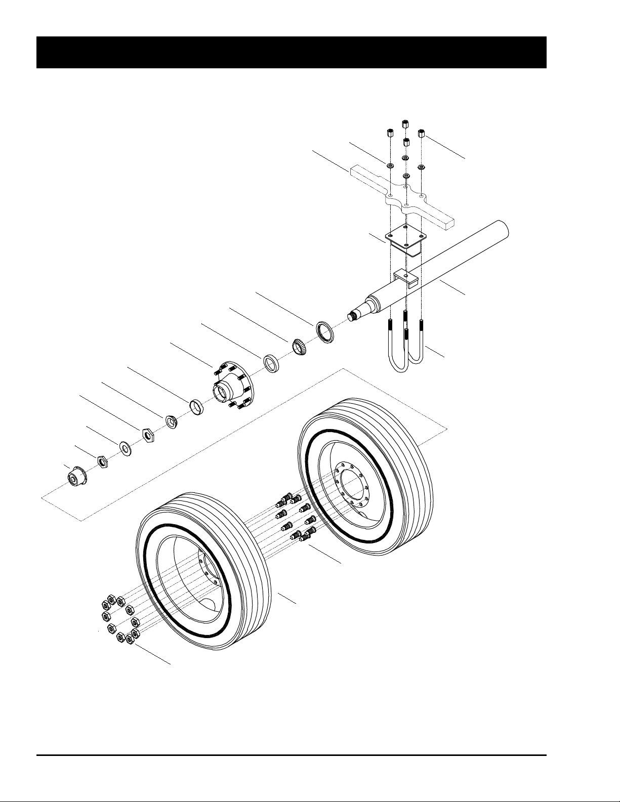
1
2
3
4
5
6
7
8
9
10
11
12
13
14
15
16
17
18
19
NOTE:
1) Axle is mirrored about
centerline. (Except for Left-Hand
lug nuts on left side of machine.)
2) Check maintenance section for
torque specications.
Axle U-Bolt Holder
welded to Frame.
HD4SR - Optional Equipment
12SR - Optional Equipment
HD4SR and 12SR
Truck Tire and Axle Assembly - Prior to 2015
9-20 October 2015 HD4SR & 12SR
Page 95

Truck Tire and Axle Assembly - Prior to 2015
Item Part No. Description Qty
1 10316 11R-24.5 14-Ply Truck Tire ............................................................................................... 4
2 10366 SR 24.5 Truck Wheel ........................................................................................................ 4
3 10409 Standard Axle Beam - 105 Lg (Includes Items 6, 7, 8, 9, 10, 11, 12, 13, 14 & 15) ......... 1
4 10043 RH Dual Lug Nut Inner ..................................................................................................... 10
10042 LH Dual Lug Nut Inner ..................................................................................................... 10
5 10045 RH Dual Lug Nut Outer .................................................................................................... 10
10044 LH Dual Lug Nut Outer .................................................................................................... 10
6 10793 RH 10-Bolt - 11.25 Hub .................................................................................................... 1
10794 LH 10-Bolt - 11.25 Hub .................................................................................................... 1
7 10792 Oil Seal ............................................................................................................................ 2
8 10791 Inside Cone Bearing ........................................................................................................ 2
9 10790 Inside Bearing Race......................................................................................................... 2
10 10789 Outside Bearing Race ...................................................................................................... 2
11 10788 Outside Cone Bearing...................................................................................................... 2
12 10787 Inside Spindle Nut ............................................................................................................ 2
13 10786 Spindle Washer ................................................................................................................ 2
14 10785 Outside Spindle Nut ......................................................................................................... 2
15 11677 Hub Oil Cap ..................................................................................................................... 2
16 10077 7/8 x 12 - 5 Round U-Bolt ................................................................................................ 4
17 10234 7/8 Heavy Duty High Plain Nut ........................................................................................ 8
18 10041 7/8 Heavy Duty Washer ................................................................................................... 8
19 10383 Riser Block - 2 inches High .............................................................................................. 2
* Quantities Listed Are For One Machine. ........................................................................
HD4SR & 12SR October 2015 9-21
Page 96
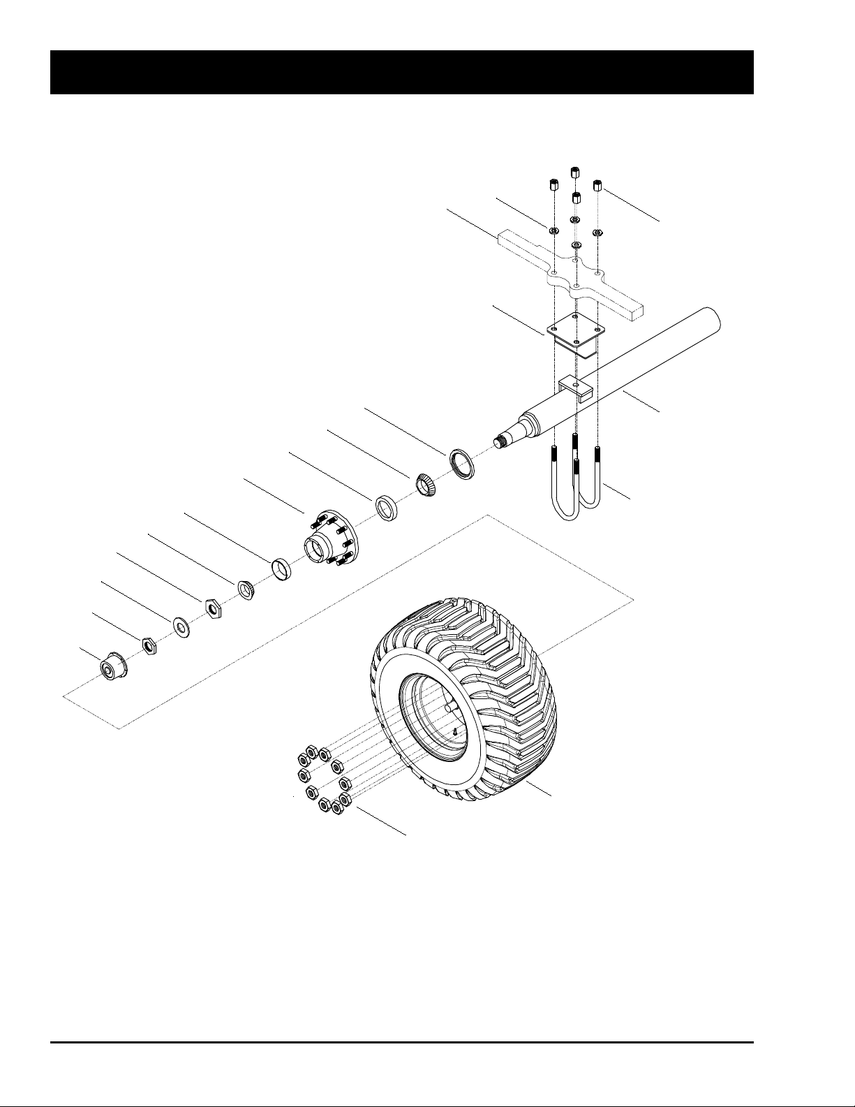
1
2
NOTE:
1) Axle is mirrored about
centerline. (Except for Left-Hand
lug nuts on left side of machine.)
2) Check maintenance section for
torque specications.
Axle U-Bolt Holder
welded to Frame.
3
4
5
6
7
8
9
10
11
12
13
14
15
16
17
18
12SR - Standard Equipment
HD4SR - Optional Equipment
HD4SR and 12SR
Terra Tire and Axle Assembly - Prior to 2015
9-22 October 2015 HD4SR & 12SR
Page 97

Terra Tire and Axle Assembly - Prior to 2015
Item Part No. Description Qty
1 10367 Rim - 20 x 22.5 - 10 Bolt .................................................................................................. 2
W-3328 Valve Stem (Not Shown)
2 10006 600/55-22.5 - 16-Ply Terra Tire ........................................................................................ 2
3 10409 Standard Axle Beam - 105 Lg (Includes Items 4, 5, 6, 7, 8, 9, 10, 11, 12 & 13) .............. 1
4 10794 LH 10-Bolt - 11.25 Hub .................................................................................................... 1
10793 RH 10-Bolt - 11.25 Hub .................................................................................................... 1
5 11677 Hub Oil Cap ..................................................................................................................... 2
6 10785 Outside Spindle Nut ......................................................................................................... 2
7 10786 Spindle Washer ................................................................................................................ 2
8 10787 Inside Spindle Nut ............................................................................................................ 2
9 10788 Outside Cone Bearing...................................................................................................... 2
10 10789 Outside Bearing Race ...................................................................................................... 2
11 10790 Inside Bearing Race......................................................................................................... 2
12 10791 Inside Cone Bearing ........................................................................................................ 2
13 10792 Oil Seal ............................................................................................................................ 2
14 10047 RH Single Lug Nut ........................................................................................................... 10
10046 LH Single Lug Nut ............................................................................................................ 10
15 10077 7/8 x 12 - 5 Round U-Bolt - Plain ..................................................................................... 4
16 10234 7/8 Heavy Duty High Plain Nut ........................................................................................ 8
17 10041 7/8 Heavy Duty Washer ................................................................................................... 8
18 10383 Riser Block - 2 inches High .............................................................................................. 2
* Quantities Listed Are For One Machine
HD4SR & 12SR October 2015 9-23
Page 98
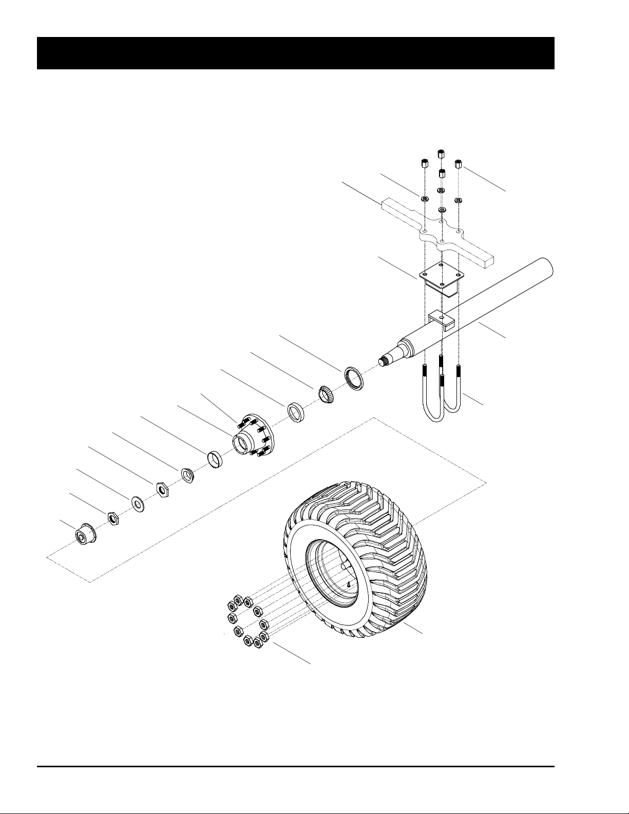
HD4SR and 12SR
1
2
NOTE:
1) Axle is mirrored about centerline.
2) Check maintenance section for
torque specifications.
Axle U-Bolt Holder
welded to Frame.
3
19
5
6
7
8
9
10
11
12
13
14
15
16
17
18
4
Terra Tire and Axle Assembly - 2015 to Present
12SR - Standard Equipment - from serial number SR12153114 and on.
HD4SR - Standard Equipment - from SR4151368 to SR4151372 and from serial number SR4151376 and on.
9-24 October 2015 HD4SR & 12SR
Page 99

Terra Tire and Axle Assembly - 2015 to Present
Item Part No. Description Qty
1 K56776 Rim - 20 x 22.5 - 10 Bolt ................................................................................................. 2
W-3328 Valve Stem (Not Shown)
2 K56777 Tire - 600/50-22.5 - 16-Ply - TVS Eurogrip .................................................................... 2
3 10409 Standard Axle Beam - 105 Lg (Includes Items 4, 5, 6, 7, 8, 9, 10, 11, 12 & 13) .............. 1
4 10793 RH 10-Bolt - 11.25 Hub (Includes wheel studs) ........................................................... 2
5 11677 Hub Oil Cap ..................................................................................................................... 2
6 10785 Outside Spindle Nut ......................................................................................................... 2
7 10786 Spindle Washer ................................................................................................................ 2
8 10787 Inside Spindle Nut ............................................................................................................ 2
9 10788 Outside Cone Bearing...................................................................................................... 2
10 10789 Outside Bearing Race ...................................................................................................... 2
11 10790 Inside Bearing Race......................................................................................................... 2
12 10791 Inside Cone Bearing ........................................................................................................ 2
13 10792 Oil Seal ............................................................................................................................ 2
14 10047 RH Single Lug Nut ......................................................................................................... 20
15 10077 7/8 x 12 - 5 Round U-Bolt - Plain ..................................................................................... 4
16 10234 7/8 Heavy Duty High Plain Nut ........................................................................................ 8
17 10041 7/8 Heavy Duty Washer ................................................................................................... 8
18 11137 Riser Block - 4 inches High ........................................................................................... 2
19 12100 RH Wheel Stud - 3/4 x 2-5/8 Lg (Vendor #s WEBB 198510 or EUCLID E4968R) ..... 20
* Quantities Listed Are For One Machine
HD4SR & 12SR October 2015 9-25
Page 100
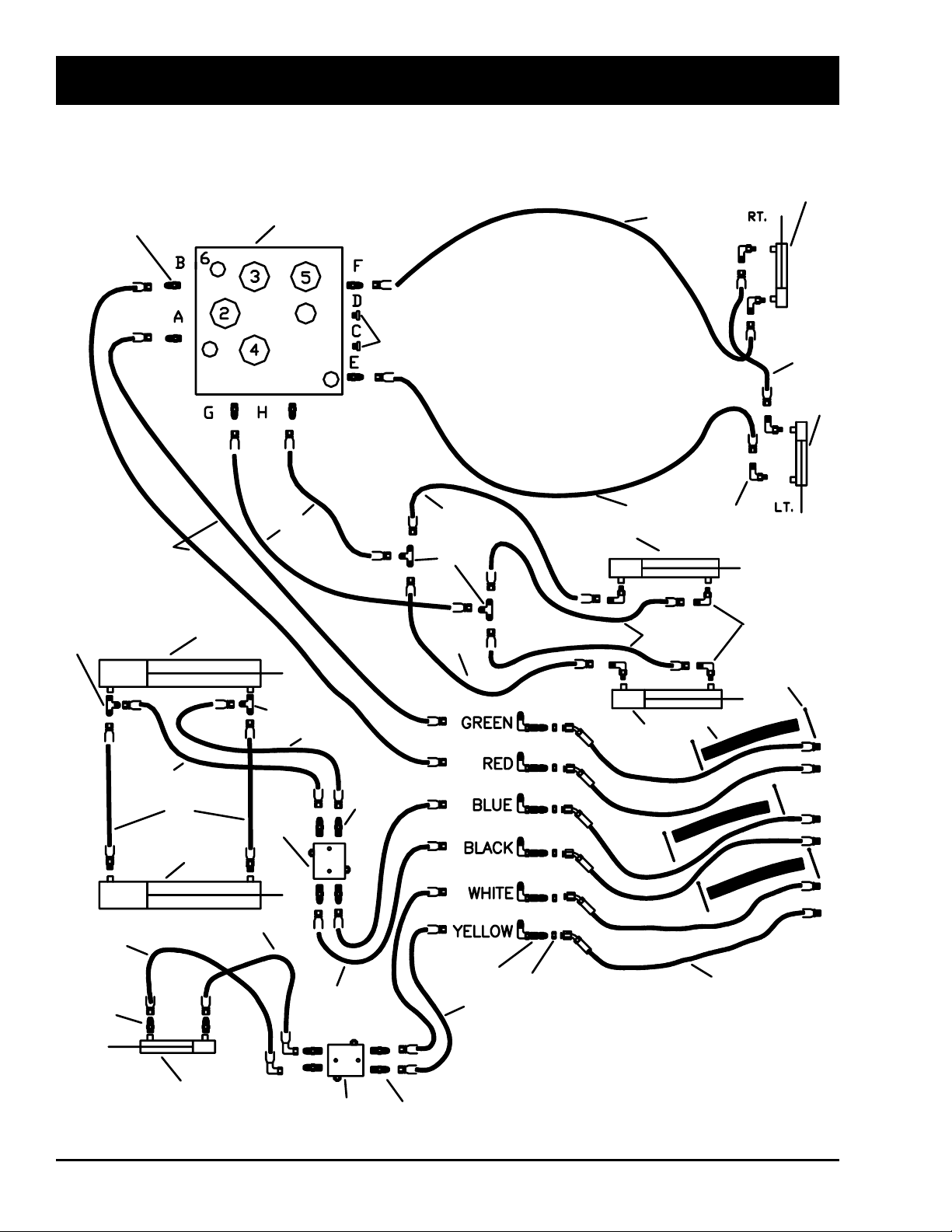
1
2
3
3
4
4
5
6
7
8
9
9
8
10
10
11
12
13
14
15
15
16
17
18
19
20
21
22
20
24
25
26
26
27
28
29
30
31
32
2
Note: This is a representation of the
parts used in the hydraulic assembly
and not a routing diagram.
D
C
B
A
B
D
C
A
HD4SR Hydraulic Hose Schematic
HD4SR and 12SR
9-26 October 2015 HD4SR & 12SR
 Loading...