

Page 1
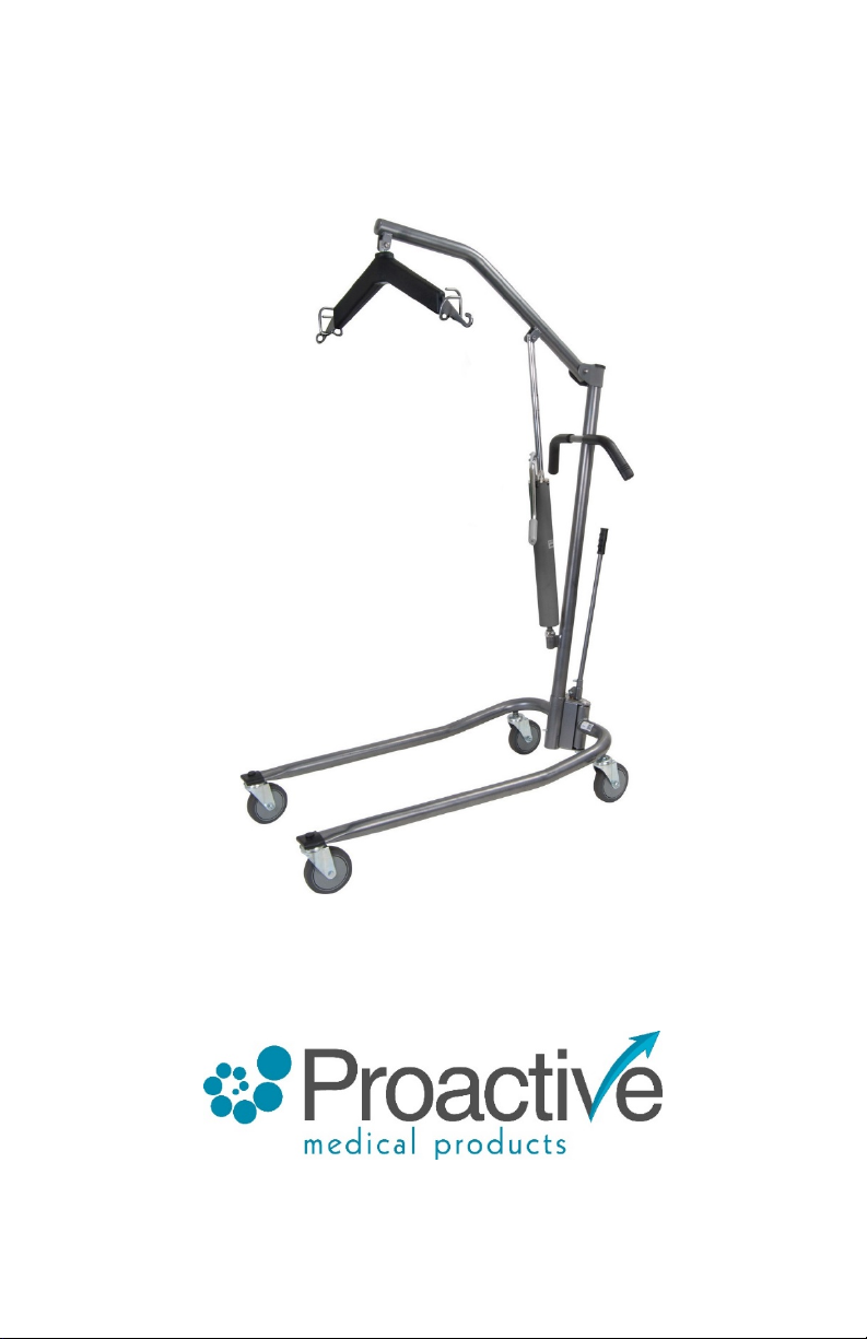
PROTEKT® ONYX
HYDRAULIC PATIENT LIFT
OWNERS MANUAL & INSTRUCTIONS
270 Washington Street
Mount Vernon, NY 10553
855-237-7622
www.proactivemedical.com
Page 2

SAFETY SUMMARY
WARNING!
Check all parts for shipping damage before using. In case of damage, do NOT use the
equipment. Contact the Dealer for further instructions.
The Proactive Medical patient lift is
an individual from one resting surface to another (such as a bed to a wheelchair).
Moving a person
suspended in a sling over ANY distance is NOT recommended.
DO NOT
medical attendant. Thoroughly read the instructions in this Owner's Manual, observe a
trained team of experts perform the lifting procedures and then perform the entire lift
procedure several times with proper supervision and a capable individual acting as a
patient.
attempt any transfer without approval of the patient's physician, nurse or
Use common sense in all lifts. Special care
individuals who cannot cooperate while being lifted. Use restraint straps if necessary.
Proactive Medical slings and patient lift accessories are specifically designed
to be used in conjunction with Proactive Medical patient lifts. Slings and
accessories designed by other
of
Proactive Medical
void
Proactive Medical
slings and lift accessories to maintain patient safety and product utility.
’s patient lift system. Use of these products is prohibited and will
's patient lift warranty. Use only genuine
Use a sling that is recommended by the individual's doctor, nurse or medical attendant
for the comfort and safety of the individual being lifted.
DO NOT
patient and sling material that may cause the patient to slide out of the sling during a
transfer.
use any kind of plastic back incontinence pad or seating cushion between the
When using an adjustable base lift, the legs
OPENED/LOCKED
position BEFORE lifting the patient.
Before transferring a patient from a stationary object (wheelchair, commode or bed),
slightly raise the patient off the stationary object and check all sling hardware for secure
attachment to include swivel bar, straps, S-hooks and D or O-rings. If any attachment is
not correct, lower the patient and correct the problem, then raise the patient and check
again.
During transfer, with patient suspended in a sling attached to the lift,
base over objects such as carpets, raised carpet bindings, door frames, or any uneven
NOT
a transport device. It is intended to transfer
MUST BE
manufacturers are not to be utilized as a component
MUST BE
taken with physically challenged
Proactive Medical
in the maximum
DO NOT
roll caster
Page 3

SAFETY SUMMARY
surfaces or obstacles that would create an imbalance of the patient lift and could cause
the patient lift to tip over. Use steering handles on the mast at
the patient lift.
After the first 12 months of operation, inspect the swivel bar and the boom (to which it
attaches) for wear. If the metal is worn, the parts MUST be replaced. Make this
inspection every three (3) months thereafter.
The hydraulic pump is sealed at the factory and if service is required, the pump unit
MUST BE
pump or obtain local service as this will VOID the warranty and may result in damage
and a
information.
Casters and axle bolts require inspection every six (6) months to check for tightness
and
Regular maintenance of the patient lift and accessories is necessary to assure proper
operation.
DO NOT
limitations will vary from 300 to 450 Ibs. depending on the type of patient lift
purchased. Refer to the
weight limitation.
returned to the factory for repair.
costly repair. Consult your Dealer or Proactive Medical for further
wear.
exceed maximum weight limitation of the patient lift. These suggested weight
SPECIFICATIONS
DO NOT
attempt to open the hydraulic
in this Owner is Manual for maximum
ALL
times to push or pull
Page 4

Item#
32475
Base Width (Inches)
OPEN: 42.25
CLOSED: 22.00
Base Height (inches)
(Clearance):
5.25
Base Length: 40.5
(inches)
Boom Height at
Sling Attachment: (inches)
Min:
17.00
Max:
61.00
Range: 44.00
Boom Overall
Height:
73.00
Weight Capacity:
450
(lbs.)
Caster Size: 5.00
(Inches)
Weight:
85 lbs.
(Unit in carton)
SPECIFICATIONS
Page 5
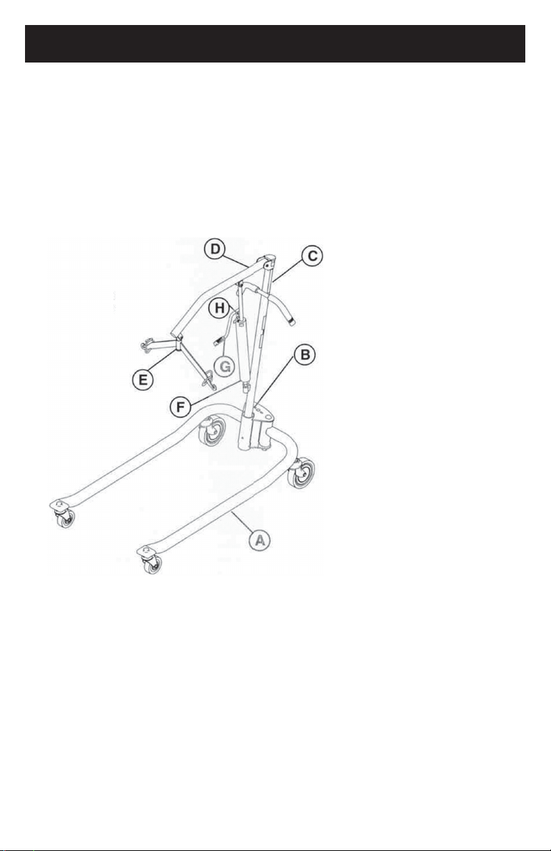
FEATURES
Hydraulic pump suggested operating limit is 450 Ibs. Masts are interchangeable with
bases. Lock together. Can be separated for storage.
Operation optimizes lift capabilities. Requires less physical effort for raising patient.
Offset mast and boom style provides better lift path. Maximizes full travel range.
Pump handle can rotate from side-to-side for convenience of attendant.
A.
The Caste red Base
B.
The Shifter Handle
C.
The Mast
D.
The Boom
E.
Swivel Bar
F.
Hydraulic Pump
G.
Pump Handle
H.
Control Valve
Page 6
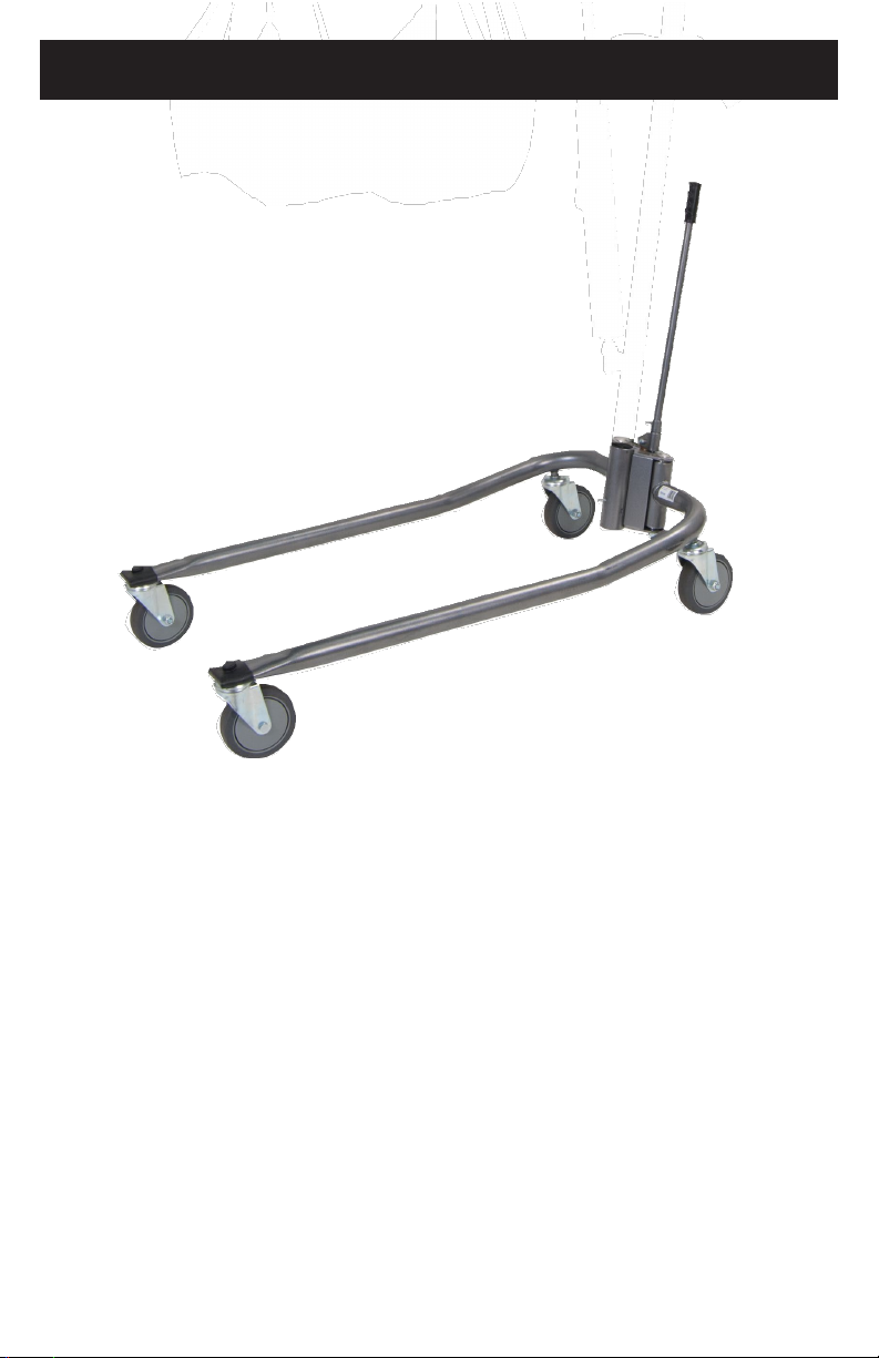
FEATURES (CONT.)
ADJUSTABLE BASE
Uses 5-inch casters in rear and 5-inch casters in front.
Opens legs from 22 to 42-1/4-inches.
Page 7

FEATURES (CONT.)
ITEM #
DESCRIPTION
30137
Standard seat/back sling - Canvas
330 lb. weight capacity
30138
Standard seat/back sling w/commode
opening - Canvas 330 lb. weight capacity
30132
Standard seat/back sling - Nylon
330 lb. weight capacity
30133
Standard seat/back sling w/commode
opening - Nylon 330 lb. weight capacity
PATIENT SLINGS
WARNING
Use a sling that is recommended by the individual's doctor, nurse or medical attendant
for the comfort and safety of the individual being lifted.
Patient slings work in conjunction with lifts to support the patient during lifting and
transferring procedures.
Slings attach to the lift by using either sewn-in loop straps, chains or adjustable straps.
Each sling offers reinforcing at each hook-on point to ensure patient safety.
Each sling is constructed of durable materials which resist deterioration from exposure
to moisture or laundering.
Standard Slings
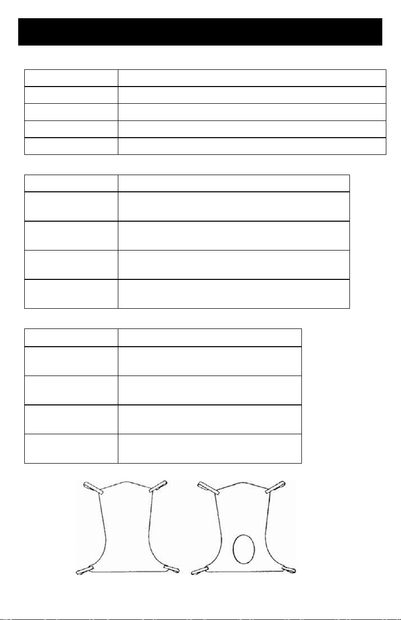
The one-piece contour sling can be used on heavy or light patients. Supports patient
from shoulders to the knees. Used for weighing, transferring or to simplify the use of
bathroom facilities.
Page 8
FEATURES (CONT.)
ITEM #
DESCRIPTION
30110 Medium
Mesh full body: medium 600 lb. weight capacity
30111 Large
Mesh full body: large 600 lb. weight capacity
30124 X-Large
Mesh full body: X-large 600 lb. weight capacity
30118 XX-Large
Mesh full body: XX-large 600 lb. weight capacity
ITEM #
DESCRIPTION
30114 Medium
Mesh full body: medium w/commode opening
600 lb. weight capacity
30115 Large
Mesh full body: large w/commode opening
600 lb. weight capacity
30116 X-Large
Mesh full body: X-large w/commode opening
600 lb. weight capacity
30119 XX-Large
Mesh full body: XX-large w/commode opening
600 lb. weight capacity
ITEM #
DESCRIPTION
30112 Medium
Solid fabric full body: medium
600 lb. weight capacity
30113 Large
Solid fabric full body: large
600 lb. weight capacity
30117 X-Large
Solid fabric full body: X-large
600 lb. weight capacity
30123 XX-Large
Solid fabric full body: XX-large
600 lb. weight capacity
Full Body Mesh Slings
Full Body Mesh Slings w/Commode
Full Body Solid Slings
Page 9

FEATURES (CONT.)
ITEM #
DESCRIPTION
30100P Small
Solid divided leg: small 450 lb. weight capacity
30100 Medium
Solid divided leg: medium 450 lb. weight capacity
30101 Large
Solid divided leg: large 450 lb. weight capacity
30102 X-Large
Solid divided leg: X-large 450 lb. weight capacity
30103 XX-Large
Solid divided leg: XX-large 600 lb. weight capacity
ITEM #
DESCRIPTION
30100P-NHS Small
Solid padded divided leg w/o head support: small
600 lb. weight capacity
30100-NHS Medium
Solid padded divided leg w/o head support: medium
600 lb. weight capacity
30101-NHS Large
Solid padded divided leg w/o head support: large
600 lb. weight capacity
30102-NHS X-Large
Solid padded divided leg w/o head support: X-large
600 lb. weight capacity
ITEM #
DESCRIPTION
30100P-HS Small
Solid padded divided leg w/head support: small
600 lb. weight capacity
30100-HS Medium
Solid padded divided leg w/head support: medium
600 lb. weight capacity
30101-HS Large
Solid padded divided leg w/head support: large
600 lb. weight capacity
30102-HS X-Large
Solid padded divided leg w/head support: X-large
600 lb. weight capacity
Divided leg design is best suited for high level spinal cord injuries or patients where sling
removal is more difficult. Support ranges from the upper back to beneath the thighs. Can
be positioned with patient seated. Greatly simplifies the use of bathroom facilities.
Divided Leg Slings
Padded Divided Leg Slings w/o Head Support
Padded Divided Leg Slings w/Head Support
Page 10
HANDLING PROCEDURES
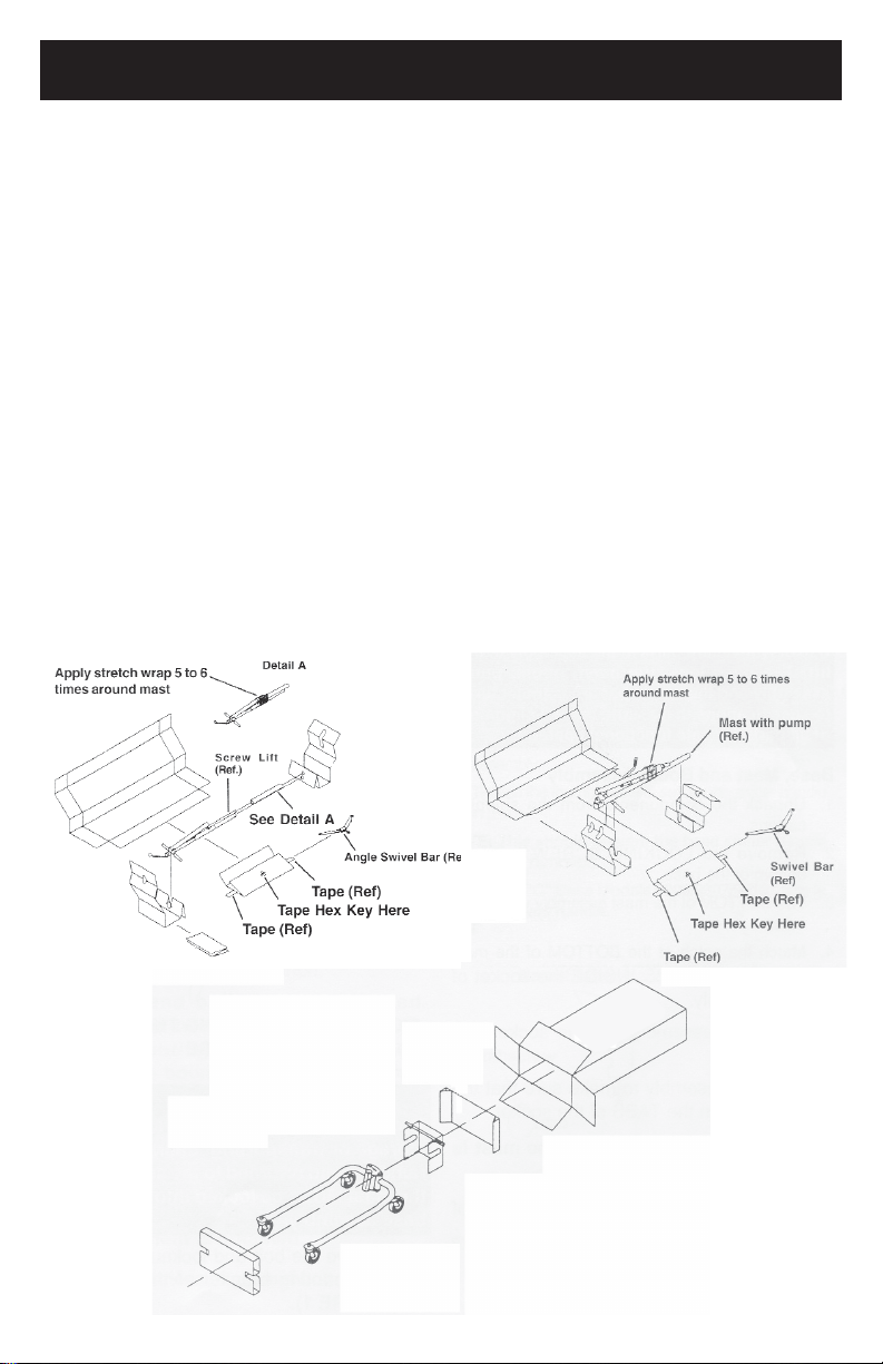
SHIPPING AND TRANSPORTATION INSTRUCTIONS
If the Patient Lift is to be reshipped by common carrier, it should be packed in the same
carton. Extra cartons are available from Proactive Medical.
UNPACKING
1.
Check for any obvious damage to the carton or its contents. If damage is evident,
notify Carrier/ Proactive Medical Dealer.
2.
Remove all loose packing from the carton.
3.
Carefully remove all the components from the carton.
NOTE:
packing material for use in storing until use of the Patient Lift is required.
INSPECTION
1. Examine exterior of the Patient Lift for nicks, dents, scratches or damages. Inspect all
components.
STORAGE
1.
Store the repackaged Patient Lift in a dry area.
2.
DO NOT place other objects on top of the repackaged Patient Lift.
Unless the Patient Lift is to be used immediately, retain boxes, containers and
Page 11
ASSEMBLY
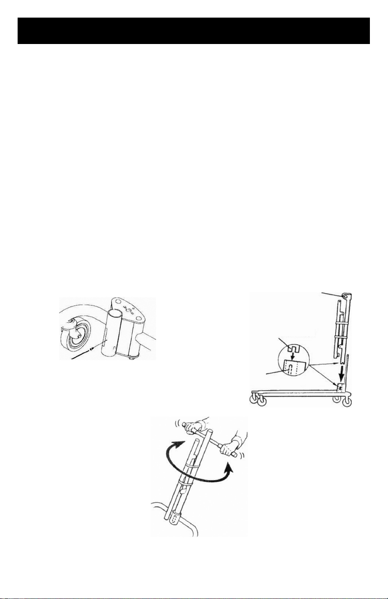
Bolt and Lockout
Bottom of mast notch
Top
the Base assembly
WARNING!
Use only Proactive Medical parts in the assembly of this lift. The base legs, the mast,
boom, pump assembly and the swivel bar are manufactured to specifications that assure
correct
alignment of all parts for safe functional operation.
BASE, MAST AND BOOM ASSEMBLY
1.
Unpack the components from the shipping cartons.
2.
Remove the LOCKING SCREW from the
bottom of the base.
3.
The BOTTOM of the mast assembly will have a notch.
4.
Match the notch at the BOTTOM of the mast assembly with the TABS INSIDE the
socket of the base assembly.
5.
Insert the mast assembly into the socket and onto the TABS.
6.
Turn the mast assembly to make sure that the notch is locked on the TABS of the
socket.
NOTE: If the mast DOES NOT turn, the mast is centered and locked in place.
7.
Insert the LOCKING SCREW into the bottom of the base and securely tighten.
inside of the Socket of
Locking
Screw
Fig. 1 - Assembling the mast to the base
Page 12
ASSEMBLY (CONT.)
WARNING!
The mast may be removed from the base for storage or transporting. Each time the mast
is removed and returned to the socket of the base, the mast MUST be locked into the
socket of the base assembly.
8.
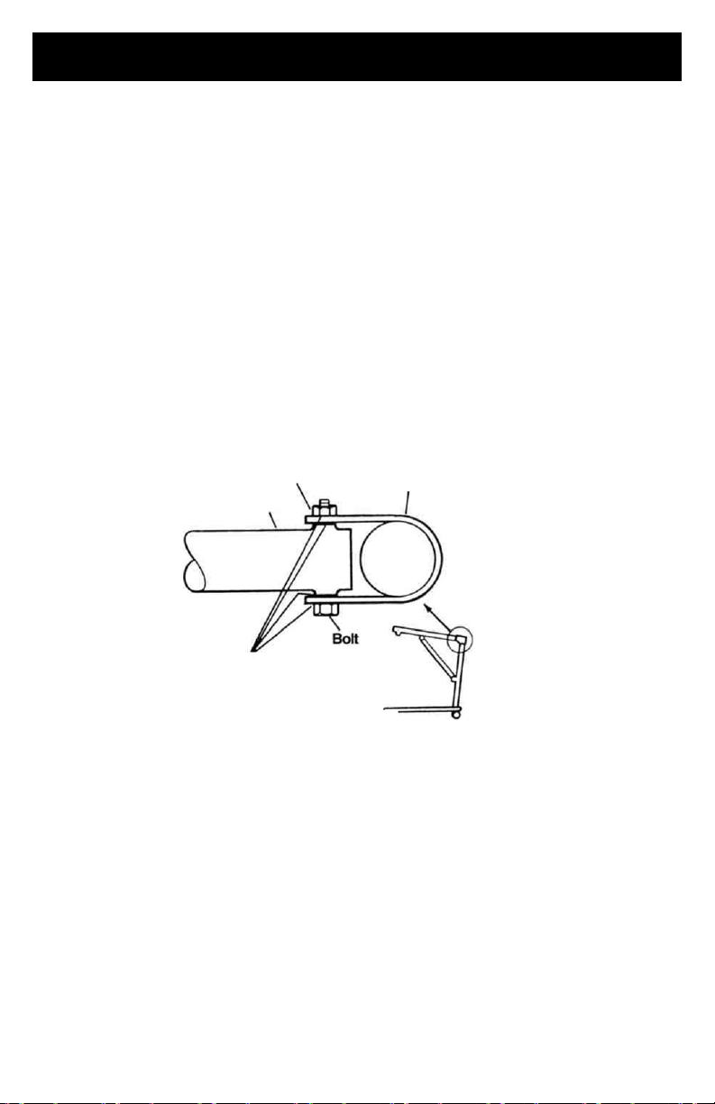
Remove the bolt and lock nut from the TOP of the mounting bracket of the mast
assembly.
9.
Align the holes of the boom assembly and mast assembly mounting bracket. Insert
the bolt completely through the holes of the mast assembly mounting bracket and the
boom assembly.
NOTE:
mounting bracket and boom assembly; and they are not riding on the shoulder of
the bolt.
Be sure that the bolt is completely through the holes of the mast assembly
Mast Assembly
Mounting Bracket
Boom Assembly
Lockout
Mast Assembly
CAUTION:
The boom and mast when assembled MUST pivot easily.
10.
Tighten the bolt and nut using the Allen wrench provided and an adjustable wrench.
NOTE:
easily if the mounting hardware is aligned properly when the boom assembly is secured
to the mast. To check for correct alignment of the hardware, use the Allen wrench
provided and turn the bolt by hand (it should rotate without a lot of force being applied).
If excessive force is necessary, the bolt is NOT aligned properly. Disassemble and repeat
assembly procedures until proper alignment is obtained.
The nut and bolt can be tightened completely and the boom assembly will pivot
Page 13
ASSEMBLY (CONT.)
11.
To check for tightness of nut and bolt:
a.
Raise the boom assembly.
b.
Push the control handle away from the pump assembly.
c.
If the boom assembly pivots easily, then the nut and bolt are NOT too tight.
d.
If the boom assembly does not pivot easily or does not pivot at all, then the nut and
bolt are NOT aligned properly.
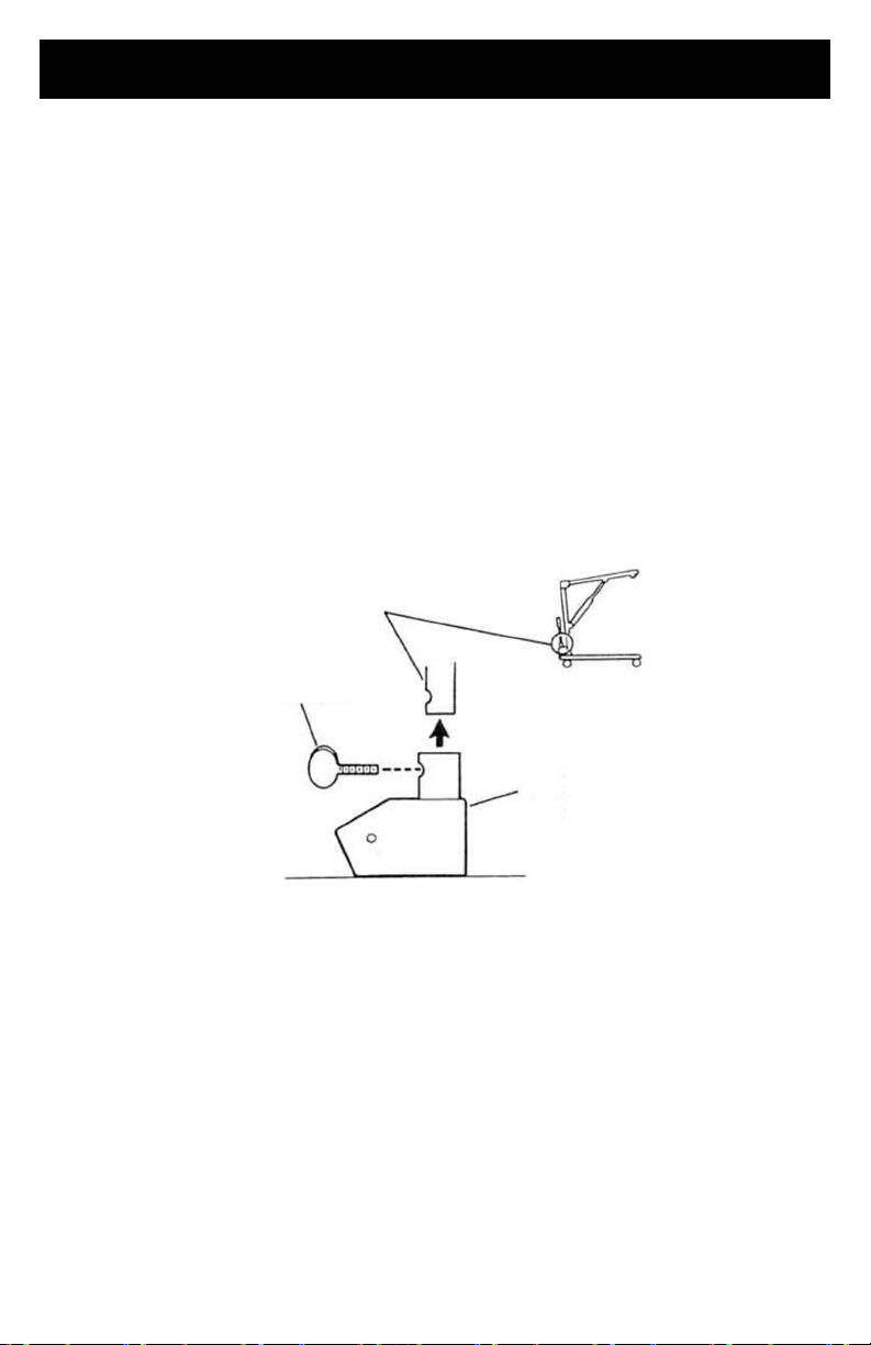
Base Shifter Handle Assembly
1.
Insert the base shifter handle into the cam lock assembly at the back of the base.
2.
Align the holes of the shifter handle and cam lock assembly.
3.
Tighten the thumb screw to secure the shifter handle in place.
NOTE: This should prevent the base shifter handle from being removed.
Base Shifter Handle
Thumbscrew
SHIFTER HANDLE INSTALLATION
Cam Lock Assembly
Page 14
ASSEMBLY (CONT.)
Nut in
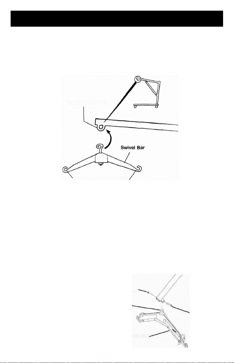
Swivel Bar
Pad
SWIVEL BAR ATTACHMENT WITH EYE AT END OF BOOM
1. Attach the swivel bar to the eye at the end of the boom.
NOTE:
sling that supports the patient during lift.
The swivel bar has hooks on both ends to accept the hardware used to attach the
Eye (End of Boom)
Sling Hardware Attachments
SWIVEL BAR ATTACHMENT WITH EYE AT END OF BOOM
SWIVEL BAR ATTACHMENT WITH MOUNTING BRACKET
1.
Push the pin and washers up through the swivel bar pad.
2.
Line up hole in pin with mounting bracket holes and secure with shoulder screw and
nut provided.
NOTE:
the sling that supports the patient during lift. The swivel bar pad should remain in place
during normal use.
NOTE:
completely pushed UP through the
Swivel Bar Pad.
The swivel bar has hooks on both ends to accept the hardware used to attach
Make sure Pin and Washers are
P
SWIVEL BAR
ATTACHMENT WITH
MOUNTING BRACKET
Shoulder
Screw
Page 15

ITEM #
DESCRIPTION
30137
Standard seat/back sling - Canvas
330 lb. weight capacity
30138
Standard seat/back sling w/commode
opening - Canvas 330 lb. weight capacity
30132
Standard seat/back sling - Nylon
330 lb. weight capacity
30133
Standard seat/back sling w/commode
opening - Nylon 330 lb. weight capacity
ONE - PIECE SLINGS
SLINGS USING CHAINS, O-RINGS AND D-RINGS
Standard Slings
Proactive Medical slings are designed specifically for use with Proactive Medical
Patient Lifts and made to support the patient during lift and transfer procedures.
Slings attach to the lift with
are reinforced at all points of attachment for safety. The fabrics used in these slings
are of very durable materials that
and laundering. This design will
support from the shoulders to the
the lift by avoiding the bulk of excess material between the back and seat
sections.
FABRIC
The fabric has a smooth inner side. The outer side has binding tape around the pocket.
NOTE:
Sling fabrics are offered in a choice of three (3) materials. Canvas, Nylon and Polyester.
Always place the sling under the patient with the smooth side next to the body.
NOTE: Laundering should always be done with dark colors.
Open mesh nylon fabric is an exceptional material that provides safety and comfort for
the patient. The open mesh weave of the fabric preshrunk, and durable for use and
laundering. It provides considerable traction to resist slipping and sliding during use.
BODY
Slings may be ordered at the time of purchase with a commode opening in the seat
section for use over a commode or a commode chair.
Each sling includes four (4) metal support bars that have a hole at the center to attach
the S-hook.
When shipped from the factory, these reinforcing metal support bars are enclosed in the
sling pocket with the hole exposed.
either straps or chains (inter-changeable). The slings
resist deterioration from exposure to moisture
accommodate patients of heavy or light weight with
knees. The contour shape provides comfort during
Page 16
ONE - PIECE SLINGS (CONT.)
FULL BODY AND PADDED “U” SLING
Slings attach to the lift with straps for easy positioning. Each loop strap is reinforced at
the hook-up point for strength and durability.
FABRIC
The outer side has a reinforced "grab handle" for assistance in positioning the patient in a
wheelchair, commode, etc. The edging is soft yet durable with extra reinforced stitching
for safety.
NOTE:
NOTE:
instructions on the sling.
Always place the sling under the patient with the handle away from the patient.
Laundering should always be done with dark colors. Refer to tagged washing
The full body and “U” sling fabrics are an exceptional material that provides safety and
comfort for the patient. They provide considerable traction to resist slipping and sliding
during use.
BODY
Slings may be ordered at the time of purchase with a commode opening in the seat
section for use over a commode or a commode chair. Slings are constructed with a high
back section and built-in headrest that provides additional support for the head and neck.
POSITIONING THE SLING (WITHOUT HEADREST)
1.
2.
NOTE: The sling seams (uneven
surface) will be against the bed surface
and facing the attendant when folded.
The opposite side of the fabric is
smooth. After the sling is positioned for
lifting purposes, the smooth side will be
next to the patient.
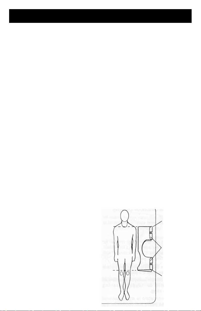
POSITIONING THE SLING (WITHOUT HEADREST)
Position the patient in the center of the bed and laying flat on his/her back.
Fold the sling in half (lengthwise) and place the fabric sections of the sling beside
the patient.
Center of Bed
Top Edge of Sling
Seams (Facing
the Attendant
and Bed
Surface)
Bottom Edge of
Sling
Page 17
ONE - PIECE SLINGS (CONT.)
3.
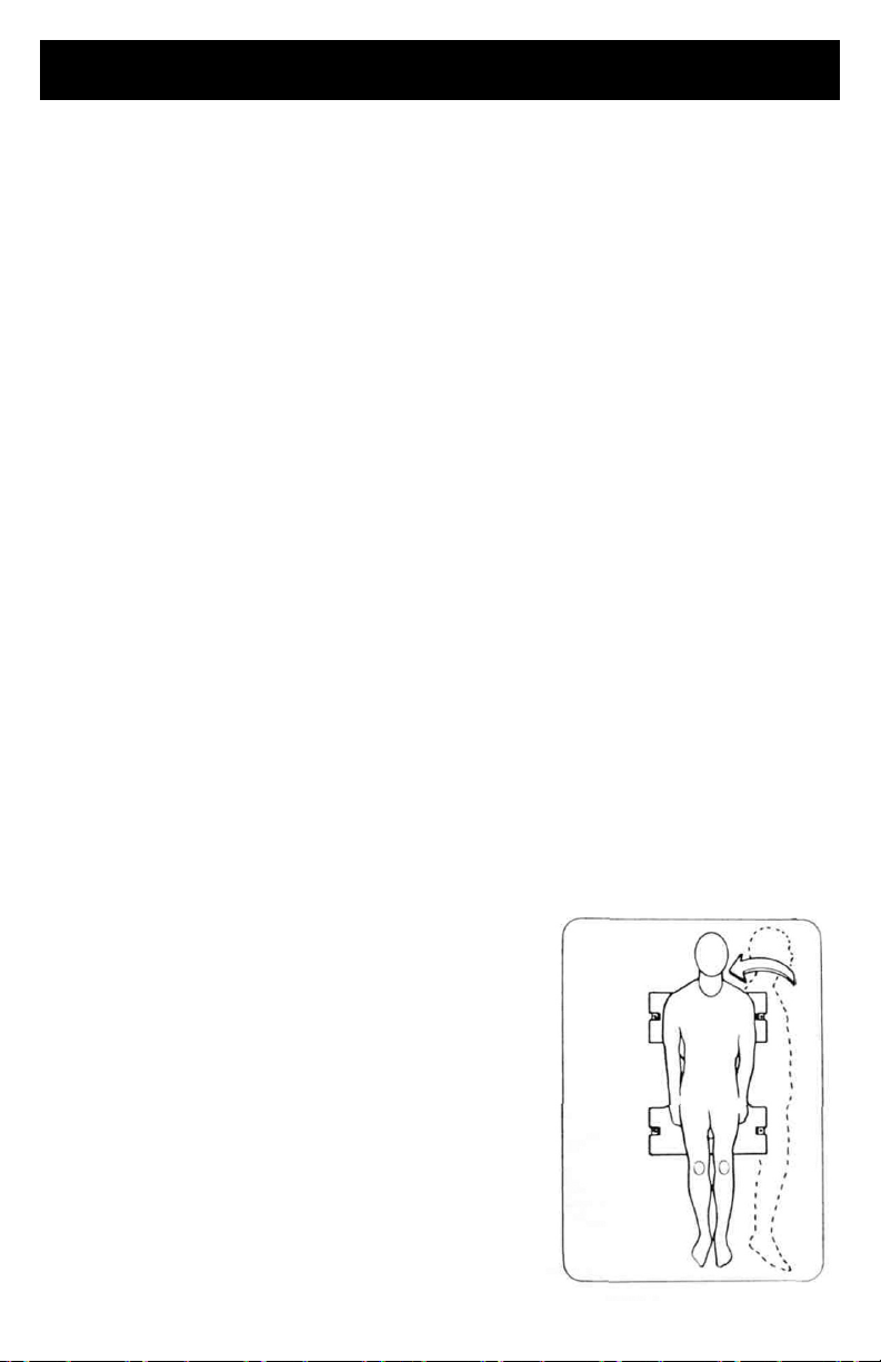
The top edge of the sling fabric (nearest to the patient's head) should be slightly
above the armpit level of the patient.
4.
The bottom edge of the sling fabric should then be a few inches above the back of
the patient's knee.
5.
With both attendants holding the patient, push the folded sling under the patient
without rolling him/her over.
POSITIONING THE PATIENT ON THE SLING
NOTE:
1.
NOTE:
the bed) be
2.
3.
Use the following method to easily move the patient and avoid strain to yourself.
If the patient is to roll to their LEFT-SIDE, then elevate the patient's RIGHT KNEE until
the right foot is flat on the bed.
Proactive Medical recommends that two (2) attendants (One [1] on each side of
used when positioning the patient in a sling.
With an attendant on each side of the bed and up against the mattress, the attendant
on the left-hand side of the bed will position his/her RIGHT-HAND on the elevated
KNEE and his/ her LEFT-HAND under the patient's RIGHT SHOULDER, slowly push
on the knee and assist with a slight lift of the shoulder and the patient will easily roll
onto their side.
With the patient on their side, push the fabrics of the seat and back gently under
them.
NOTE: The upper edge of the back section should be positioned slightly above the
armpit level and the lower edge of the seat section positioned a few inches above the
back of the patient's knees.
4.
Roll the patient on to his/her back. NOTE: Attendants will reverse roles.
5.
After the patient has been positioned once again on his/her back, you now need to
roll the patient to their RIGHT-SIDE (facing the attendant on the LEFT).
6.
With an attendant on each side of the bed and up
against the mattress, the attendant on the righthand side of the bed will elevate the LEFT KNEE
and position his/her LEFT-HAND on the elevated
KNEE and his/her RIGHT-HAND under the patient's
LEFT SHOULDER. The attendant will slowly push
on the knee and assist with a slight lift of
the shoulder and the patient will easily roll onto
their side.
7.
Pull the fabrics of the seat and back across the
mattress until they are smooth.
8.
Roll the patient onto their back and they should be
approximately centered on the sling.
9.
You are now ready to attach the chains or straps to
the sling.
PATIENT CENTERED
IN SLING
Page 18

PADDED, “U” SLINGS
NOTE:
one [1] in back
NOTE:
WARNING
the chair from moving forward or backwards.
Proactive Medical recommends that two (2) attendants (One [1] in front and
of the wheelchair) be used when positioning the patient in the sling.
Use the following method to easily move the patient and avoid strain to yourself.
:
If the patient is in a wheelchair, secure the wheel locks in place to prevent
1.
With the patient sitting in a chair one (1) attendant in the front and the other
attendant in the back, lean the patient forward.
NOTE: The front attendant will be supporting the weight of the patient.
2.
Place the sling behind the patient and bring the flaps out alongside the patient’s legs.
NOTE:
arms and be positioned between the top of the patient's back and the top of the chair
back.
The back of the sling (mounting area) should be parallel to the patient's upper
3.
With the back of the sling positioned properly, push the edges of the commode
opening under the patient’s buttocks.
4.
Lean the patient back into the chair with the attendant in the rear supporting his/her
weight.
5.
Lift the patient's legs (one at a time) while holding the leg panel of the sling, reach
under the patient's leg and pull until the leg panel of the sling is behind the patient's
knees (about three [3] inches) and the back of the sling remains in position.
6.
The straps may be crossed BETWEEN or UNDERNEATH the patient's legs.
7.
Refer to Attaching the Slings to the Patient Lift in LIFTING THE PATIENT Section of
this manual.
Page 19
Strap Over
ATTACHING THE SLING HARDWARE
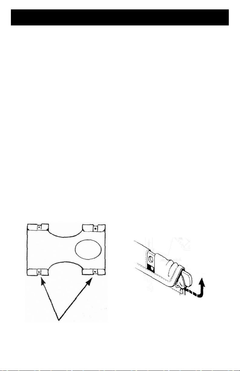
The hardware used with the one-piece contour sling includes four (4) metal support
bars. The hardware inserts into the pockets at the edge of the fabric. The pocket that will
hold the metal bar has an opening in the center. The pocket is sewn closed on one end
and has an open-end with a strap on the other.
NOTE:
MUST be replaced or the sling cannot be used for lifting purposes.
Inserting the Four (4) Metal Support Bars into the Sling
NOTE:
in the center of the strap (after it has been pulled down) and push the metal support bar
into the sling pocket. The sling is sewn on both sides so the center location is critical.
1.
2.
3.
NOTE:
where the S-hook of the chain or strap will be attached.
When the slings are laundered, remove the four (4) metal support bars. They
When inserting each metal bar into the sling pocket, align the metal support bar
To insert the metal support bar, pull the strap down allowing the bar to pass through
the opening in the sling pocket.
Push the metal support bar through until the mounting hole clears the center
opening of the sling pocket.
Once the opposite end of the bar is inside the sewn pocket, push the strap over the
metal support bar to prevent it from falling out.
The hole in the metal bar should be in the center of the pocket opening. This is
Metal Support Bars with
Openings for Chains or Straps
Metal
Support Bar
Page 20
D-Ring
ATTACHING THE SLING HARDWARE (CONT.)
CAUTION
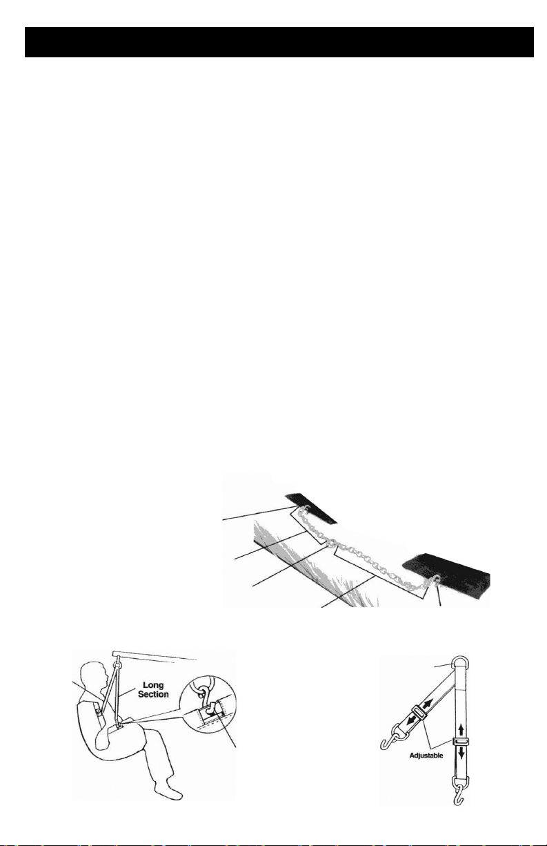
lift, the shortest of the two (2) sections of the chains or straps MUST be attached to the
back section of the sling. Using the long section will leave little or no support for the
patient's back.
1.
With the patient laying on his/her back and positioned properly in the sling, lay the
chains or straps on the bed next to the sling.
2.
The short section of chain or strap will be placed parallel to the patients back. This
will position the longer section of chain or strap from the waist to the mid-section of
the thigh.
3.
The S-hooks on the ends of the chains or straps are inserted into the metal support
bar of the sling.
4.
The S-hook MUST be inserted through the hole in the support bar with the open end
facing away from the patient.
5.
The O-ring of the chain assembly is the suggested location to attach to the swivel
bar, however, by changing to different links, you can reposition the patient into a
reclining or more upright position.
WARNING
chains from the swivel bar. Position BOTH the O-rings and additional chain link onto the
hooks of the swivel bar.
6.
The straps can be simply adjusted to achieve the same effect.
7.
With the sling positioned under the patient, and the metal support bars in place, you
are now ready to move the lift into position to attach the sling hardware to the
swivel bar.
S-Hook Open-End Away from patient
Short
Section
- When using either the chains or straps to connect the sling to the patient
- When changing to different lengths, DO NOT disconnect the O-rings of the
Short Section of Chain
O-Ring
Long Section of Chain Long Section of Chain
S-Hook Open
End Away
From Patient
Page 21

ATTACHING THE FULL BODY AND PADDED “U” SLING
NOTE:
proceeding further and observe all WARNINGS indicated.
WARNING
in the OPEN position for optimum stability and safety.
NOTE:
area is clear of any obstructions.
Refer to PATIENT LIFT SAFETY SUMMARY in the front of this manual before
- Before lifting or transferring the patient, the base legs MUST be LOCKED
Before positioning the legs of the patient lift under the bed, make sure that the
1.
With the legs of the base OPEN and LOCKED, use the steering handle to push the
patient lift underneath the bed.
2.
Lower the patient lift for easy attachment of the sling.
3.
Place the straps of the sling over the hooks of the swivel bar.
CAUTION
MUST be at the back of the patient for support. Using the long section will leave little or
no support for the patient's back.
- When connecting the sling to the patient lift, the shortest of the straps
Page 22
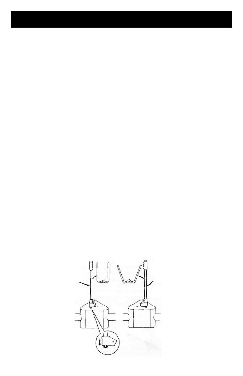
OPERATION
Shifter
Handle
Shifter
Handle
Locked
OPERATING THE PATIENT LIFT
To Open the Legs of the Adjustable Base
WARNING!
attempt any transfer without approval of the patient's physician, nurse or medical
attendant. Thoroughly read the instructions in this Owner's Manual, observe a trained
team of experts performing the lifting procedures and then perform the entire lift
procedure several times with proper supervision and a capable individual acting as a
patient.
ONLY operate this lift with the legs in maximum open position and locked in place. The
base legs MUST be locked in the open position at all times for stability and patient safety
when lifting and transferring a patient.
The Shifter handle is used to open the legs of the base for stability when lifting a patient.
1.
Grasp the shifter handle in one hand and place the opposite hand on the steering
handle of the mast for balance.
2.
Push the shifter handle to your RIGHT to release the lock pin from its
mounting hole.
3.
Turn the handle CLOCKWISE until you are able to secure the lock pin into the opposite
mounting hole to fully open the legs of the base.
-
The operation of the patient lift is an easy and safe procedure. DO NOT
NOTE:
the legs in the full open position. The shifter handle will be in the vertical position;
parallel with the mast assembly.
WARNING-
socket assembly. DO NOT use the patient lift until lock pin is properly seated and
LOCKED in place or injury and/or damage may occur.
The lock pin MUST insert into its mounting hole in the socket assembly to lock
If the shifter handle is NOT vertical, the lock pin is NOT seated in the
Base Closed Base Open
TO OPEN THE LEGS OF THE ADJUSTABLE BASE
Page 23
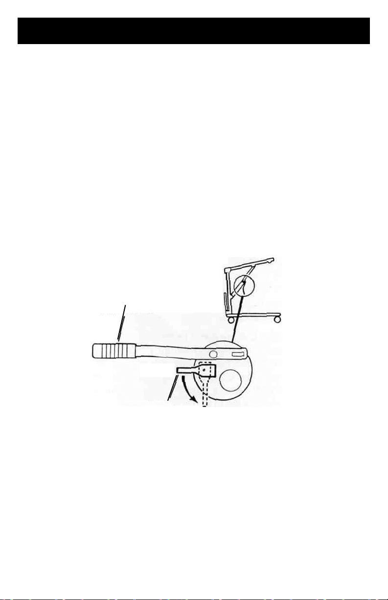
OPERATION (CONT.)
Pump Handle
Closed
Control Valve
Open
There are two (2) controls on the pump assembly:
1.
The control valve
2.
The pump handle
RAISING THE LIFT.
positioned towards pump handle) to move the pump handle up and down to elevate the
boom and the patient.
LOWERING THE LIFT.
valve positioned away from pump handle) to lower the boom and the patient. The rate of
descent can be controlled by varying the amount that the control valve is opened.
NOTE:
descent of the boom regardless of how far the control valve is
A safety gate is part of the hydraulic system that maintains a SLOW constant
The control valve MUST be in the CLOSED position (control valve
The control handle MUST be in the OPEN position (control
RAISING/LOWERING THE HYDRAULIC PATIENT LIFT
Page 24
LIFTING THE PATIENT
NOTE:
proceeding further and observe all WARNINGS indicated.
WARNING-
open position for optimum stability and safety.
Refer to PATIENT LIFT SAFETY SUMMARY in the front of this manual before
Before lifting or transferring the patient, the base legs MUST be locked in the
1.
Using the steering handle, push the patient lift underneath the bed.
2.
Lower the patient lift for easy attachment of the sling hardware or straps.
3.
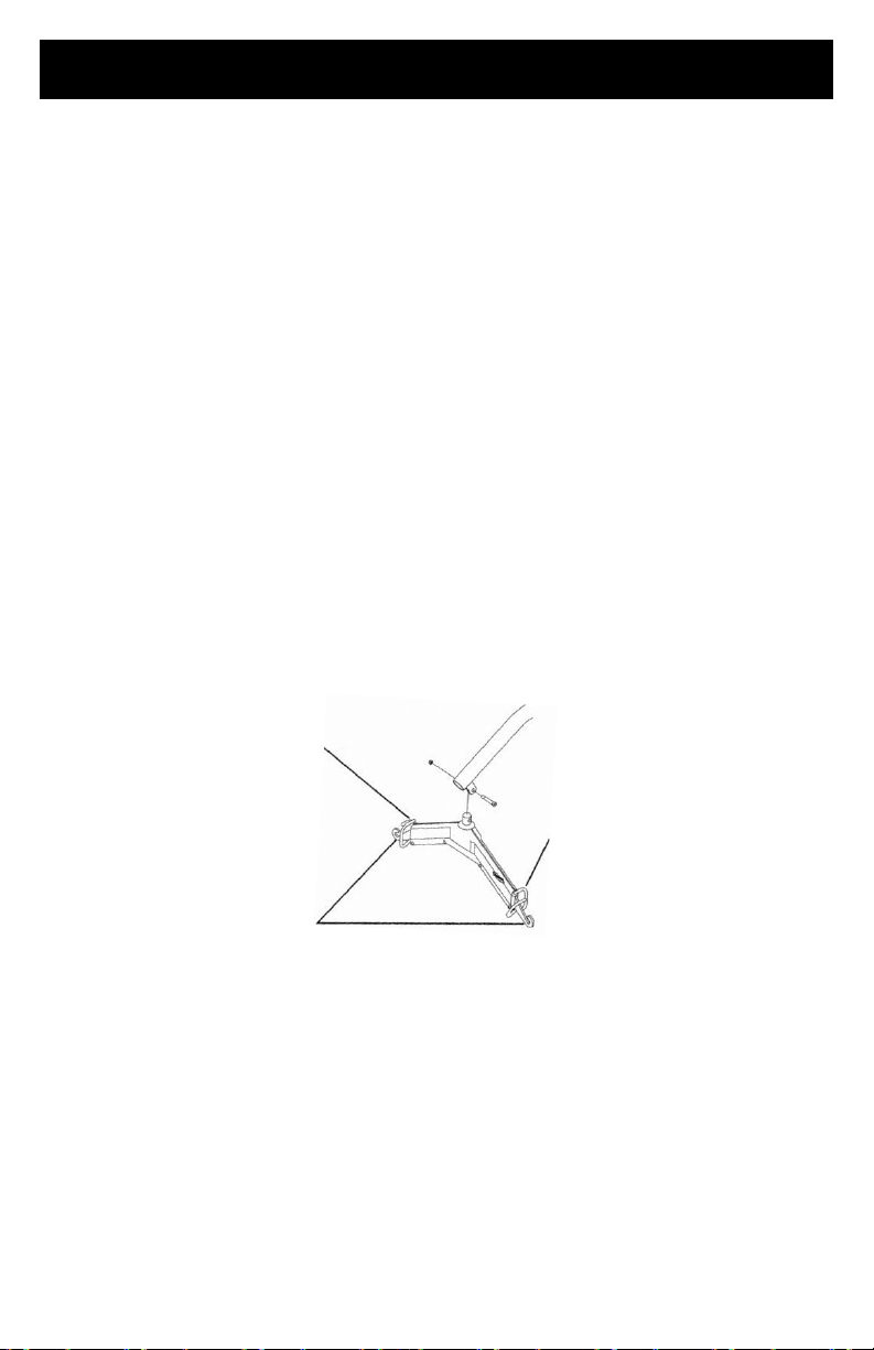
Chains, 0-Rings and D-Rings:
After the chains, O-Rings or D-Rings are attached and the S-hooks are secured in
both sides of the sling sections (open end facing outward), place the D-rings of the
strap assembly or the O-ring and chain link of the chain assembly over the chain
hooks of the swivel bar.
4.
Chain-Free Full Body and Padded “U” Slings:
Attach the straps to the strap hooks of the swivel bar.
WARNING
HOOKS of the Swivel Bar. ONLY attach CHAINS, 0-RINGS or D-RINGS to CHAIN HOOKS of
the Swivel Bar. DO NOT change or intermix attachment points or serious injury may occur.
- ONLY attach STRAPS of the Full Body and Padded “U” Slings to the STRAP
Strap Hooks
Strap Hooks
5.
Pump the lift handle or turn the handle clockwise (clicking sound is normal) to raise
the patient above the bed. The patient should be elevated high enough to clear the
bed and their weight supported by the lift.
NOTE:
lock in place.
NOTE:
Chain Hooks
ATTACHING THE SLING TO THE SWIVEL BAR
The manual (crank) lift handle will automatically turn back one (1) quarter turn to
On a hydraulic lift, the boom will stay in position until the control valve is opened.
Page 25

LIFTING THE PATIENT (CONT.)
6.
When the patient is lifted from the bed (with the patient's head supported), he/she
will be raised to a sitting position.
NOTE:
and transfer.
WARNING
the patient, check again to make sure that all hardware is properly connected. Check
each S-hook to make sure it is completely attached to the metal support bars of the
sling. Check the attachment of the straps, O or D-rings to the swivel bar hooks. If any
attachments are NOT properly in place, lower the patient back onto the bed and correct
this problem.
Adjustments for safety and comfort should be made before moving the patient. Patient's
arms should be inside of the chains or straps.
7.
8.
9.
10.
NOTE:
and the lift easier to pull or push.
11.
NOTE: DO NOT use the rear locking casters when patient is in the lift.
A headrest sling may be used for support for the patient's head during elevation
- When elevated a few inches off the surface of the bed and before moving
When patient is clear of the bed surface, swing their feet off the bed.
Using the steering handles, move the patient lift away from the bed.
When moving the patient lift away from the bed, turn patient so that he/she faces
attendant operating the patient lift.
Open control valve lowering patient so that his feet rest on or over the base of the
lift, straddling the mast. Close control valve.
The lower center of gravity provides stability making the patient feel more secure
Pull the patient lift away from the bed and push from behind with both hands.
Page 26

TRANSPORTING PATIENT FOR USE OF BATHROOM FACILITIES
TRANSPORTING PATIENT FOR USE OF COMMODE CHAIR OR STANDARD COMMODE
TRANSFERRING TO A COMMODE CHAIR
The slings with commode openings are designed to be used with either a commode
chair or standard commode.
NOTE:
bar during the
WARNING
standard commode and before moving the patient, check again to make sure that all
hardware or straps are properly connected. Check each S-hook to make sure it is
completely attached to the metal bars of the sling. Check the attachment of the straps, O
or D-rings to the swivel bar hooks. If any attachments are NOT properly in place, lower
the patient back onto the commode chair or standard commode to correct this problem.
Adjustments for safety and comfort should be made before moving the patient. Patient's
arms should be inside of the chains or straps.
Proactive Medical does NOT recommend locking of the rear casters of the patient lift
when lifting an individual. Doing so could cause the lift to tip and endanger the patient
and assistants.
UNLOCKED during lifting procedures
patient is initially lifted from a chair, bed or any stationary object.
1.
2.
3.
4.
5.
6.
7.
Proactive Medical recommends that the sling remain connected to the swivel
patient's use of either the commode chair or standard commode.
- When elevated a few inches off the surface of the commode chair or
Proactive Medical DOES recommend that the rear casters be left
to allow the patient lift to stabilize itself when the
The patient should be elevated high enough to clear the commode chair and their
weight supported by the lift.
With the help of both attendants, guide the patient onto the commode chair.
Lower the patient onto the commode chair leaving the sling attached to the
swivel bar.
When complete, recheck for correct attachment and then raise the patient off of the
commode chair.
When patient is clear of the commode surface (using the steering handles), move the
lift away from the commode chair.
To return patient to bed, reverse procedures concerning lifting the patient, operation
and sling attachment.
To return or place patient in a wheelchair, refer to TRANSFERRING TO A
WHEELCHAIR in this manual.
Page 27

TRANSPORTING PATIENT FOR USE OF BATHROOM FACILITIES
TRANSFERRING TO A STANDARD COMMODE
NOTE:
bathroom facilities before using the patient lift again to position the patient on a standard
commode. Refer to TRANSFERRING TO A WHEELCHAIR in this manual. After this has
been accomplished refer to the following:
1.
2.
3.
4.
5.
6.
7.
8.
The patient MUST be transferred to a WHEELCHAIR and transported to the
To lift the patient from the bed, follow the procedures concerning lifting the patient,
operation and sling attachment.
The patient should be elevated high enough to clear the standard commode and their
weight supported by the patient lift.
With the help of both assistants, guide the patient onto the standard commode.
Lower the patient onto the standard commode leaving the sling attached to the
swivel bar hooks.
When complete, recheck for correct attachment and then raise the patient off of the
standard commode.
When patient is clear of the standard commode surface (using the steering handles),
move the lift away from the standard commode.
To return or place a patient in a wheelchair, refer to TRANSFERRING TO A
WHEELCHAIR in this manual.
To return patient to bed, reverse procedures concerning lifting the patient, operation
and sling attachment.
WARNING-
patient, check again to make sure that all hardware or straps are properly connected.
Check each S-hook to make sure it is completely attached to the metal support bars of
the sling. Check the attachment of the straps, O or D-rings to the swivel bar hooks. If any
attachments are NOT properly in place, lower the patient completely to correct this
problem.
When elevated a few inches off the surface of the bed and before moving the
Adjustments for safety and comfort should be made before moving the patient. Patient's
arms should be inside of the chains or straps
1.
To remove the patient from the bed, observe procedures concerning sling
attachment, operation and lifting the patient.
2.
The patient should be elevated high enough to clear the bed and be able to slide the
portable bathtub under the patient.
3.
Lower the patient into the portable bathtub.
4.
Detach chains/straps from sling and reattach to the portable bathtub.
5.
Using the lift, raise the sides of the portable bathtub.
6.
Bathe patient.
7.
Reverse procedures to return patient to bed.
Page 28

TRANSFERRING TO A WHEELCHAIR
NOTE:
WARNING-
before moving the patient, check again to make sure that all hardware and straps are
properly connected. Check each S-hook to make sure it is completely attached to the
metal support bars of the sling. Check the attachment of the straps, 0 or D- rings to the
swivel bar hooks. If any attachments are NOT properly in place, lower the patient
completely to correct this problem.
Adjustments for safety and comfort should be made before moving the patient. Patient's
arms should be inside of the chains or straps.
Proactive Medical does NOT recommend locking of the rear casters of the patient lift when
lifting an individual. Doing so could cause the lift to tip and endanger the patient and
assistants.
Proactive Medical DOES recommend that the rear casters be left UNLOCKED during lifting
procedures
from a chair, bed or any stationary object.
1.
2.
WARNING-
patient into the wheelchair for transport
3.
4.
5.
6.
7.
8.
Proactive Medical recommends that two (2) attendants be used when
transferring a patient
When elevated a few inches off the seating surface of the wheelchair and
to allow the patient lift to stabilize itself when the patient is initially lifted
The legs of the lift (w/patient) are in the opened position.
The wheelchair is moved into position.
Wheelchair wheel locks MUST be in a locked position before lowering the
The rear wheel locks are locked to further prevent movement of the chair.
The patient is positioned over the seat with their back against the back of the chair.
Begin to lower the patient either by opening the control valve or by turning the crank
counterclockwise.
With one (1) attendant behind the chair and the other operating the patient lift, the
attendant behind the chair will pull back on the handle or sides of the sling to
place the patient into the back of the chair. This will maintain a good center of
balance and prevent the chair from tipping forward.
The sling is disconnected from the patient lift.
To return to the bed, reverse procedures concerning lifting the patient, operation and
sling attachments.
to a wheelchair.
Page 29

TRANSFERRING FROM A WHEELCHAIR TO A CAR
NOTE:
NOTE: Proactive Medical recommends that two (2) attendants be used when
transferring a patient from a wheelchair to a car.
WARNING-
before moving the patient, check again to make sure that all hardware or straps are
properly connected. Check each S-hook to make sure it is completely attached to the
metal support bars of the sling. Check the attachment of the straps, 0 or D-rings to the
swivel bar hooks. If any attachments are NOT properly in place, lower the patient
completely to correct this problem.
Adjustments for safety and comfort should be made before moving the patient. Patient's
arms should be inside of the chains or straps.
Proactive Medical does NOT recommend locking of the rear casters of the patient lift when
lifting an individual. Doing so could cause the lift to tip and endanger the patient and
assistants.
Proactive Medical DOES recommend that the rear casters be left UNLOCKED during lifting
procedures
from a chair, bed or any stationary object.
NOTE:
NOTE:
NOTE:
1.
2.
3.
4.
5.
6.
7.
To position an individual in a sling, follow the procedures concerning lifting the
patient, operation and sling attachments.
When elevated a few inches off the seating surface of the wheelchair and
to allow the patient lift to stabilize itself when the patient is initially lifted
The transfer to a car should be made on a level driveway or surface.
Before lifting the patient from the chair, make sure to shorten the distance
between the patient and the boom. This will make the transfer into the seat of
the car easier.
Attendants should practice "Good Body Mechanics" when positioning patient
onto any seating surface.
Attach the chains or straps to swivel bar.
Engage the rear wheel locks of the wheelchair.
Lift the patient from the wheelchair.
The lift is moved, by the steering handles, to a position close to the
doorway of the car.
Lower the boom of the lift until it is about even with the roof of the car.
As one (1) attendant pushes the patient into the car by his knees until he/she is
positioned over the seat of the car, the other attendant lowers the boom. As the
boom is being lowered, the first assistant is not only pushing but turning the patient
so he/she is positioned facing the front of the car.
The patient will come to rest on the seat of the car.
Page 30

TRANSFERRING FROM A WHEELCHAIR TO A CAR (CONT.)
8.
While one (1) attendant is holding the patient, the other attendant removes the
chains or straps from the swivel bar and slides the patient lift out of the way.
9.
The sling may be left under the patient or removed.
10.
The mast, boom and pump assembly may be removed from the base and
transported in the car.
NOTE:
taken not to damage the spokes of the wheelchair on the steering handles of the lift.
If the lift and wheelchair are both packed in the trunk of the car, care should be
Page 31

TRANSFERRING FROM A CAR TO A WHEELCHAIR
NOTE:
transferring a patient
WARNING-
patient, check again to make sure that all hardware or straps are properly connected.
Check each S-hook to make sure it is completely attached to the metal support bars of
the sling. Check the attachment of the straps, O or D-rings to the swivel bar hooks. If any
attachments are NOT properly in place, lower the patient completely to correct this
problem.
Adjustments for safety and comfort should be made before moving the patient. Patient’s
arms should be inside of the chains or straps.
Proactive Medical does NOT recommend locking of the rear casters of the patient lift when
lifting an individual. Doing so could cause the lift to tip and endanger the patient and
assistants.
Proactive Medical DOES recommend that the rear casters be left UNLOCKED during lifting
procedures
from a chair, bed or any stationary object.
NOTE: One (1) assistant will support patient at all times.
1.
2.
3.
4.
NOTE:
onto any seating surface.
5.
6.
7.
8.
9.
WARNING-
patient into the wheelchair for transport.
10.
Proactive Medical recommends that two (2) attendants be used when
from a wheelchair to a car.
When elevated a few inches off the seat of the car and before moving the
to allow the patient lift to stabilize itself when the patient is initially lifted
With the first assistant supporting the patient, the second assistant then lowers the
boom of the patient lift until the hooks of the swivel bar are even with the roof of
the car.
Attach the sling to the swivel bar.
Lift the patient up off of seat until straps are taut.
Turn patient with sling until legs are outside of car.
Attendants should practice "Good Body Mechanics" when positioning patient
Lift up on legs with one (1) hand and tilt the patient back with the other hand.
The second assistant should pull the patient lift away from the car until the patient is
completely clear of the door frame.
Release the patient back to his/her normal
sitting position in the sling.
Position the wheelchair under the patient.
Engage the rear wheel locks of the wheelchair.
Wheelchair wheel locks MUST be in a locked position before lowering the
One (1) assistant will slowly lower the patient into the wheelchair while the other
assistant guides him/her into the chair.
Page 32

CARE AND MAINTENANCE OF YOUR PATIENT LIFT
NOTE:
patient lift in continuous service.
The Proactive Medical Patient Lift is designed to provide a maximum of safe, efficient
and
All parts of the Proactive Medical Lift are made of the best grades of steel, but metal to
metal contact
There is no adjustment or maintenance of either the casters or brakes, other than
cleaning, lubrication and checking axle and swivel bolts for tightness. Remove all debris,
etc. from the wheel and swivel bearings. If any parts are worn, replace these parts
immediately.
If you question the safety of any part of the lift, contact your Dealer immediately and
advise him/ her of your problem.
HYDRAULIC PUMP
All parts of the Hydraulic Pump are precision machined, then carefully assembled and
tested to ensure reliable service. The pump assembly is completely enclosed and sealed
with Neoprene rings to prevent leakage of hydraulic oil. A small amount of oil (about a
drop) will accumulate around the piston from time to time and should be removed with a
facial tissue.
WARNING-
pump unit MUST be returned to the factory for repair. DO NOT attempt to OPEN the
hydraulic pump or obtain local service. This will void the warranty and might result in
damage and costly repair. Consult your dealer for information.
Follow the maintenance procedures described in this manual to keep your
satisfactory service with minimum care and maintenance.
will wear after considerable use.
The hydraulic pump is sealed at the factory and if service is required, the
LUBRICATION
however, a six (6)
and reliability.
- The Proactive Medical lift is designed for minimum maintenance;
month check and lubrication should ensure continued safety
Keep lift and slings clean and in good working order. Any defect should be noted and
reported to your dealer as soon as possible.
The casters MUST swivel and roll smoothly. A light grease (waterproof auto lubricant)
may be applied to the ball bearing swivel of the casters once a year. Apply more
frequently if the casters are exposed to extreme moist conditions.
The connection between the mast and the base should be cleaned and coated with
petroleum jelly prior to assembly.
Page 33

CARE AND MAINTENANCE OF YOUR PATIENT LIFT
Lubricate all pivot points. Wipe all excess lubricant from lift surface.
1.
2.
3.
4.
5.
6.
7.
WEAR AND DAMAGE
It is important to inspect all stressed parts, such as slings, spreader bar and any pivot
for slings for signs of cracking, fraying, deformation or deterioration. Replace any
defective parts immediately and ensure that the lift is not used until repairs are made.
All sling metal parts should be inspected every three (3) months, and if wear is apparent,
replacement must be made.
CLEANING
The sling should be washed regularly in water temperature of 14OF (60°C) and a
biological solution. A soft cloth, dampened with water and a small amount of mild
detergent, is all that is needed to clean the patient lift. The lift can be cleaned with
nonabrasive cleaners. Auto wax or furniture polish will help maintain the sparkling
finish
Swivel Bar at Mounting Bracket
Boom Mounting Bracket
Boom to Mast Mount
Mast Mounting Bracket
Base to Mast Mount
Rear Casters
Front Casters
over a long period of time.
Page 34

MAINTENANCE SAFETY INSPECTION CHECKLIST
ITEM
INITIALLY
INSPECT
MONTHLY
INSPECT
PERIODICALLY
Check all hardware and swivel bar supports.
THE CASTER BASE
Inspect for missing hardware.
Lift Base opens/closes with ease.
Inspect roll pin to ensure secure base.
Inspect casters and axle bolts for tightness.
Inspect casters for smooth swivel and roll.
Apply a light grease to caster ball bearings.
SHIFTER HANDLE
Operates smoothly.
Locks adjustable base whenever engaged.
Check roll pin for wear.
THE MAST
Mast should lock securely when assembled.
Inspect for bends or defections.
THE BOOM
Inspect for bends or defections.
Inspect bolted joints of boom for wear.
Inspect to ensure that the boom is centered
between the base legs.
ADJUST
X
X
X
X
X
X
X
X
X
X
X
X
X
X
X
X
X
X
X
X
X
X
X
X
X
X
ADJUST
X
X
X
X
THE SWIVEL BAR
Check the hooks for wear or damaged.
Check sling hooks for wear or deflection.
THE PUMP ASSEMBLY
Check for leakage.
Inspect hardware on mast and boom.
Check for wear or deflection of rod
(IF DAMAGED, RETURN TO FACTORY.)
THE PUMP HANDLE
Check for smooth operation.
X
X
X
X
X
X
X
X
X
X
X
X
X
X
X
X
X
Page 35

MAINTENANCE SAFETY INSPECTION CHECKLIST
ITEM
INITIALLY
INSPECT
INSPECT
THE CONTROL VALVE
Easy to maneuver and closes easily.
CLEANING
Whenever necessary.
SLINGS AND HARDWARE
CHECK ALL SLING HARDWARE
Inspect sling attachments and material
Inspect nylon web straps for wear.
Chains, S-hooks, O-Rings and D-Rings
each time it is used to ensure proper
connection and patient safety.
for wear.
ADJUST
MONTHLY
X
X
X
X
X
X
X
ADJUST
PERIODICALLY
X
X
Page 36

LIMITED WARRANTY
Your Proactive Medical brand product is warranted as follows: Limited lifetime warranty on the frame 1 year limited warranty on the pump and lift components.
This device was built to exacting standards and carefully
inspected prior to shipment. This Lifetime Limited Warranty is
an expression of our confidence in the materials and
workmanship of our products and our assurance to the
consumer of years of dependable service.
This warranty does not cover device failure due to owner
misuse or negligence, or normal wear and tear. The warranty
does not extend to non-durable components, such as rubber
accessories, casters, and grips, which are subject to normal
wear and need periodic replacement.
If you have a question about your Proactive Medical device or
this warranty, please contact an authorized Proactive Medical
dealer.
 Loading...