

Page 1
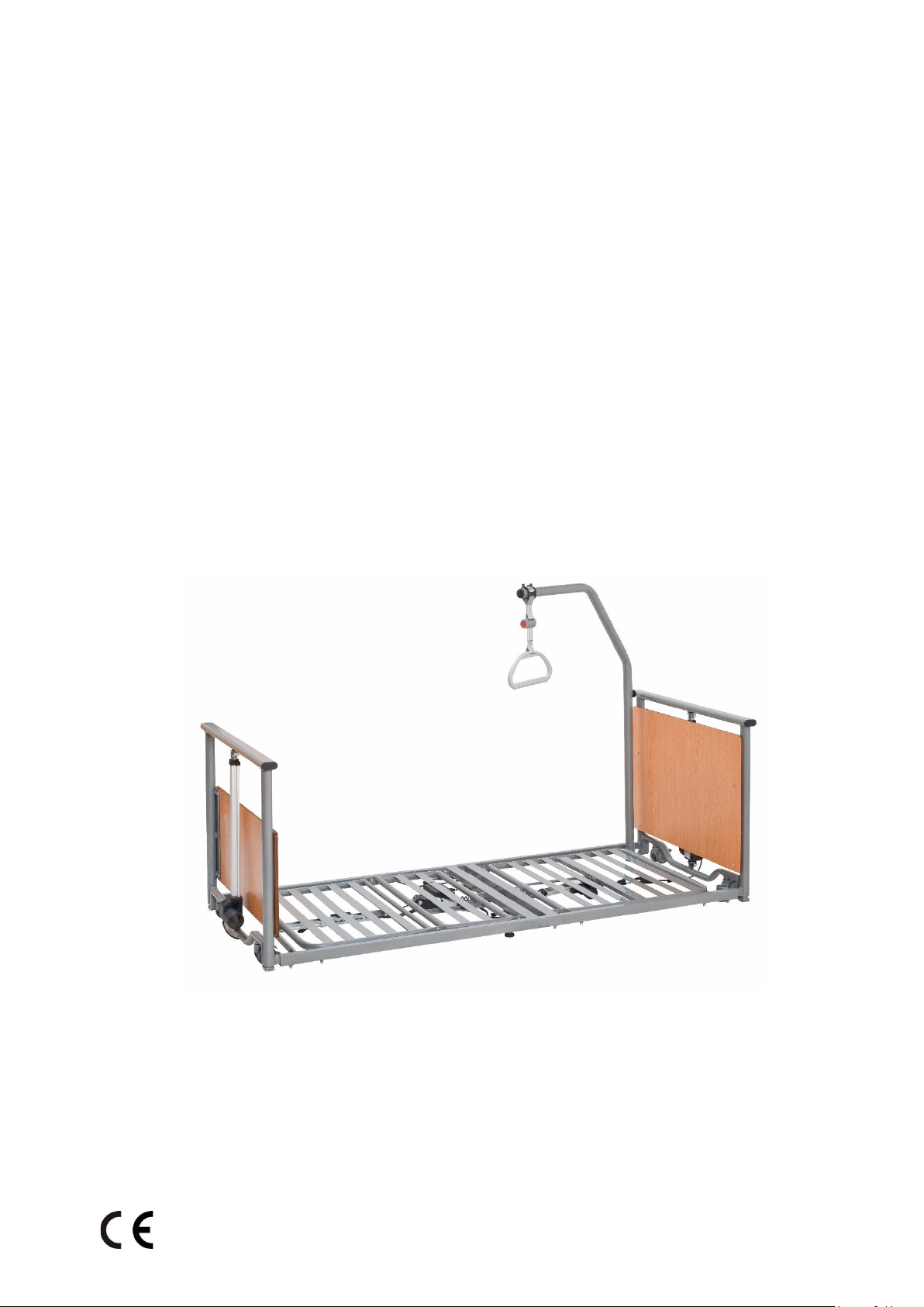
Instruction manual
(original instruction manual)
Assembly and operation
Last update:11.10.202
DESCEND
(Ultra-Low Bed)
2
Page 2

Instruction manual DESCEND
_______________________________________
Index
Foreword ..................................................................................................................................... 4
1
General information ......................................................................................................... 5
1.1 Explanation of the symbols used ................................................................................... 5
1.2 Explanation of the designated groups of persons ............................................................ 6
2
Intended purpose ............................................................................................................. 8
2.1 Intended use (application environment) ........................................................................ 8
2.2 Unauthorized use......................................................................................................... 8
3
Safety instructions ........................................................................................................... 9
3.1 General safety instructions ........................................................................................... 9
3.2 Safety instructions for the operator ............................................................................... 9
3.3 Safety instructions for the user ................................................................................... 10
3.4 Cleaning and disinfection ............................................................................................ 10
1
.
.
.
.
.
.
.
.
.
.
.
.
.
.
.
.
.
.
.
.
.
.
.
.
.
.
.
.
.
.
.
.
.
.
.
.
.
.
.
.
.
.
.
.
.
.
.
.
.
.
.
.
.
.
.
.
.
.
.
.
.
.
.
.
.
.
.
.
.
.
.
.
.
.
.
.
.
.
.
.
.
.
.
.
.
.
.
.
.
.
.
.
.
.
r
ai
p
e
r
d
an
e
c
an
n
e
t
n
ai
M
5
.
3
3.6 Accessories / Options ................................................................................................. 11
3
.
7
St
o
r
ag
e
.
.
.
.
.
.
.
.
.
.
.
.
.
.
.
.
.
.
.
.
.
.
.
.
.
.
.
.
.
.
.
.
.
.
.
.
.
.
.
.
.
.
.
.
.
.
.
.
.
.
.
.
.
.
.
.
.
.
.
.
.
.
.
.
.
.
.
.
.
.
.
.
.
.
.
.
.
.
.
.
.
.
.
.
.
.
.
.
.
.
.
.
.
.
.
.
.
.
.
.
.
.
.
.
.
.
.
.
.
.
.
.
.
.
.
.
.
1
3.8 Useful life and disposal............................................................................................... 11
12
.
.
.
.
.
.
.
.
.
.
.
.
.
.
.
.
.
.
.
.
.
.
.
.
.
.
.
.
.
.
.
.
.
.
.
.
.
.
.
.
.
.
.
.
.
.
.
.
.
.
.
.
.
.
.
.
.
.
.
.
.
.
.
.
.
.
.
.
.
.
.
.
.
.
.
.
.
.
.
.
.
.
.
.
.
.
.
.
.
.
.
.
.
.
.
.
.
.
.
.
t
or
p
s
n
a
r
t
nd
a
e
g
a
or
4
5
t
S
Assembly and commissioning ........................................................................................ 12
1
.
.
.
.
.
.
.
.
.
.
.
.
.
.
.
.
.
.
.
.
.
.
.
.
.
.
.
.
.
.
.
.
.
.
.
.
.
.
.
.
.
.
.
.
.
.
.
.
.
.
.
.
.
.
.
.
.
.
.
.
.
.
.
.
.
.
.
.
.
.
.
.
.
.
.
.
.
.
e
c
i
v
e
d
t
r
o
p
s
an
r
t
e
h
t
m
o
fr
al
v
mo
e
R
1
.
5
5
.
2
Co
n
t
r
o
l
o
f
t
h
e
d
e
l
i
v
e
r
y
a
n
d
t
h
e
s
co
p
e
o
f
d
e
l
i
v
e
r
y
.
.
.
.
.
.
.
.
.
.
.
.
.
.
.
.
.
.
.
.
.
.
.
.
.
.
.
.
.
.
.
.
.
.
.
.
.
.
.
.
.
.
.
.
.
.
.
.
.
.
.
.
.
.
.
.
.
.
1
5.3 Assembling the Descend............................................................................................. 14
5.
4 Erector with triangle handle (accessory) ...................................................................... 18
5.5 Foldable side rails (accessories- item number BC 1.19.0270000) .................................... 19
1
.
.
.
.
.
.
.
.
.
.
.
.
.
.
.
.
.
.
.
.
.
.
.
.
.
.
.
.
.
.
.
.
.
.
.
.
.
.
.
.
.
.
.
.
.
.
.
.
.
.
.
.
.
.
.
s
l
ai
r
e
d
i
s
l
e
e
t
s
e
h
t
g
n
i
s
u
n
e
wh
s
n
o
i
t
c
u
r
t
s
n
i
y
t
Safe
1
5.
5.
5.5.2 Assembly of the steel-side rails ................................................................................. 20
2
.
.
.
.
.
.
.
.
.
.
.
.
.
.
.
.
.
.
.
.
.
.
.
.
.
.
.
.
.
.
.
.
.
.
.
.
.
.
.
.
.
.
.
.
.
.
.
.
.
.
.
.
.
.
.
.
.
.
.
.
.
.
.
.
.
.
.
.
.
.
.
.
.
.
.
.
.
.
.
.
.
.
.
.
.
.
.
.
.
.
.
.
.
.
.
.
.
.
.
.
.
.
.
.
.
.
g
n
i
n
o
i
s
s
mmi
Co
6
.
5
5.7
Disassembling the Descend care bed .......................................................................... 21
0
1
2
4
9
1
6
Functional description .................................................................................................... 22
6.1
6.
6.3 Locking function for handset ....................................................................................... 23
6.4 Operation of the lockable track rollers ......................................................................... 24
6
Technical overview of the Descend ............................................................................. 22
2
H
an
d
c
o
n
t
r
o
l
wi
t
h
l
o
c
k
i
n
g
fu
n
c
t
i
o
n
.
.
.
.
.
.
.
.
.
.
.
.
.
.
.
.
.
.
.
.
.
.
.
.
.
.
.
.
.
.
.
.
.
.
.
.
.
.
.
.
.
.
.
.
.
.
.
.
.
.
.
.
.
.
.
.
.
.
.
.
.
.
.
.
.
.
.
.
.
.
.
.
.
.
.
.
.
.
.
.
.
.
.
.
.
.
.
.
.
.
.
.
.
.
.
.
.
.
.
.
.
.
.
.
.
.
.
.
.
.
.
.
.
.
.
.
.
.
.
.
.
.
.
.
.
.
.
.
.
.
.
.
.
.
.
.
.
.
.
.
.
.
.
.
.
.
.
.
.
.
g
n
i
r
e
w
o
l
cy
n
e
g
r
e
m
E
5
.
.
.
.
.
.
.
.
.
.
.
.
.
.
2
2
.
.
.
.
.
.
.
.
.
.
.
.
.
6.5.1 Emergency lowering via integrated 9V battery (electric) .............................................. 24
6.5.2 Battery change ........................................................................................................ 24
6.5.3 Emergency lowering of the backrest (manual) ............................................................ 25
6.6
7
8
9
9
9.2 Maintenance plan ...................................................................................................... 29
9.3 Check of first-error safety by means of locking function in manual switch ....................... 31
10 Warranty ......................................................................................................................... 31
11 Useful life and disposal .................................................................................................. 31
12 Technical specifications ................................................................................................. 32
Trendelenburg / Reverse Trendelenburg function (option) ............................................. 26
..
.
.
..
.
.
.
..
.
.
.
..
.
.
.
..
.
.
.
..
.
.
..
.
.
.
..
.
.
.
..
.
.
.
..
.
.
..
.
.
.
..
.
.
.
..
.
.
.
..
.
.
.
..
.
.
..
.
.
.
..
.
on
i
ct
e
nf
i
is
d
d
an
ng
eani
l
c
re,
a
C
..
.
.
.
..
.
.
.
..
.
.
.
..
.
.
..
.
.
.
..
.
.
.
..
.
.
.
..
.
.
..
.
.
.
..
.
.
.
..
.
.
.
..
.
.
.
..
.
.
..
.
.
.
..
.
.
.
ons
i
t
unc
lf
a
m
of
y
ed
rem
nd
a
use
a
C
Maintenance ................................................................................................................... 28
..
.
.
.
..
.
.
.
..
.
.
..
.
.
.
..
.
.
.
..
.
.
.
..
.
.
.
..
.
.
..
.
.
.
..
.
.
.
..
.
.
.
..
.
.
..
.
.
.
..
.
.
.
..
.
.
.
..
.
.
.
..
.
.
..
.
.
.
..
.
.
.
..
.
.
.
..
.
.
als
t
n
dame
n
u
F
1
.
27
.
.
..
.
.
.
28
.
.
..
.
.
.
28
.
.
..
.
.
.
3
4
Last update:11.10.2022
Page 2 of 40
Page 3

Instruction manual DESCEND
_______________________________________
12.1 Technical data (mechanical) ....................................................................................... 32
.
.
.
.
.
.
.
.
.
.
.
.
.
.
.
.
.
.
.
.
.
.
.
.
.
.
.
.
.
.
.
.
.
.
.
.
.
.
.
.
.
.
.
.
.
.
.
.
.
.
.
.
.
.
.
.
.
.
.
.
.
.
.
.
.
.
.
.
.
.
.
.
.
.
.
.
.
.
.
.
.
.
.
.
.
.
.
.
)
l
a
c
i
r
ct
e
l
e
(
a
t
a
d
l
ca
i
n
ch
e
T
2
.
2
1
12.3 Technical data environment ........................................................................................ 33
.
.
.
.
.
.
.
.
.
.
.
.
.
.
.
.
.
.
.
.
.
.
.
.
.
.
.
.
.
.
.
.
.
.
.
.
.
.
.
.
.
.
.
.
.
.
.
.
.
.
.
.
.
.
.
.
.
.
.
.
.
.
.
.
.
.
.
.
.
.
.
.
.
.
.
.
.
.
.
.
.
.
.
.
.
.
.
.
.
.
.
.
.
.
.
.
.
.
.
.
.
.
.
.
.
.
n
o
i
at
c
fi
i
s
as
Cl
4
.
2
1
12.5 Identification plates ................................................................................................... 33
12.6 Information on electromagnetic compatibility ............................................................... 35
2
3
.
.
.
3
3
.
.
.
13 Declaration of conformity .............................................................................................. 39
e!
s
u
h
c
ea
re
o
ef
b
s
n
o
i
t
c
ru
t
s
n
i
g
n
i
t
ra
e
p
o
e
es
h
t
e
erv
s
b
o
d
n
a
d
rea
e
s
ea
l
P
!
l
nua
a
m
n
o
i
t
c
u
r
st
n
i
s
i
h
t
e
ud
l
nc
i
e
s
a
e
l
p
,
p
hi
s
r
wne
o
e
ng
ha
c
u
o
y
f
I
Last update:11.10.2022
Page 3 of 40
Page 4

Instruction manual DESCEND
_______________________________________
Foreword
Dear customer,
The Prius Healthcare team would like to thank you for the trust you have placed in our Descend care
bed. With the decision to purchase a care bed from "Prius Healthcare" you receive a care product with
high functionality at the highest safety level.
With the purchased care bed, we can guarantee you optimal lying comfort.
All beds are carefully checked by our staff before delivery.
The healthcare bed delivered to you has left our premises in perfect condition.
When you receive the healthcare bed, the responsibility for its proper and intended operation also passes
to you at the same time.
These instructions for use inform you as the operator and your users about the function and safe
handling of the Descend healthcare bed in their daily work.
Please always keep the instructions for use at hand near the healthcare bed.
We are convinced that our product will make a positive contribution to your care.
Yours sincerely
The Prius Healthcare Team
Last update:11.10.2022
Page 4 of 40
Page 5
Instruction manual DESCEND
_______________________________________
1 General information
Before the first use:
Read the instruction manual conscientiously and completely!
Please pay attention to the various safety instructions. The Descend nursing bed should be cleaned
and disinfected before using it for the first time and before each use.
Prius Healthcare care beds carry the CE mark and meet the requirements for safety and functionality.
The Descend healthcare bed has been tested according to international standards, which include the
safety requirements for medical products.
However, these safety requirements can only be met if the user is satisfied that the patient bed
(including accessories) is in proper condition before use.
Please note the Medical Device Operator Ordinance (MPBetreibV, 2021).
1.1 Explanation of the symbols used
In these instruction manual, important information is indicated by the following symbols:
Read information with this symbol carefully and observe it urgently. This information
is relevant to safety.
This symbol warns of dangerous voltage. There is a danger to life!
This symbol warns of general dangers. There is danger to life and health
Mark of conformity according to Medical Devices Regulation (EU) 2017/745
Manufacturing date
Manufacturer of the medical device
Medical device
Serial number
IPX4
Last update:11.10.2022
r
te
a
w
ng
i
h
s
la
p
s
st
n
i
a
ag
t
en
m
p
i
qu
e
l
ca
i
r
t
ec
l
e
of
n
io
t
c
e
ot
r
P
Symbol for device of protection class II, double protective insulation
Symbol for type B application part according to IEC 60601-1
Page 5 of 40
Page 6
Instruction manual DESCEND
Requirements to be met by the operator
_______________________________________
The nursing bed may only be used indoors
The product must be sent to a separate waste collection system in the European Union.
e
t
s
a
w
d
l
o
h
e
s
u
o
h
l
a
m
r
o
n
h
t
i
w
l
a
s
po
s
i
D
S
y
m
bo
l
f
o
r
di
r
e
c
t
c
u
r
r
e
n
t
(
DC
)
d.
e
t
t
i
m
r
e
p
t
o
n
s
i
~
Symbol for alternating current (AC)
Symbol for safe working load
Symbol for maximum patient weight
S
y
m
b
o
l
f
o
r
r
e
a
d
i
n
g
t
h
e
i
n
s
t
ru
c
t
i
o
n
m
a
n
u
a
l
1.2 Explanation of the designated groups of persons
O
p
e
r
a
t
or
The operator of a medical device is any natural or legal person who is responsible for the operation of
the health facility in which the medical device is operated or used by its employees. Contrary to sentence
1, the operator of a medical device which is owned by a member of the medical profession or the
medical profession and which is brought into a health facility for use by this member shall be the
relevant member of the medical profession or the medical profession. A person is also considered to be
t
i
l
i
c
a
f
r
o
y
n
a
p
m
o
c
s
i
h
n
i
s
e
i
t
i
l
i
c
a
f
h
t
l
a
e
h
f
o
e
d
i
s
t
u
o
e
s
u
r
o
f
dy
a
e
r
s
e
c
i
v
e
d
l
a
c
di
e
m
s
p
e
e
k
e
h
f
i
r
o
t
a
r
e
p
o
n
a
or in public space. [§2, paragraph 2, MPBetreibV, 2021]
y
•
Please note that for you as the operator of this medical device, the requirements of the Medical
Device Operator Ordinance (MPBetreibV, 2021) are binding.
•
The Descend nursing bed is a medical device and may only be operated and used in accordance with
its intended purpose and the regulations of the MPBetreibV, the relevant legal regulations as well as
the generally recognised rules of technology.
•
Only instruct persons to use this medical device who have the necessary training or knowledge and
experience and who have been instructed in the medical device to be used.
•
Instruct the user in the proper handling of this medical device and document the instruction in an
appropriate form.
•
A combination with other medical devices (including accessories) or with other objects may only be
operated and used if they are suitable for use in this combination, considering the intended purpose
and the safety of patients, users, employees or third parties.
Last update:11.10.2022
Page 6 of 40
Page 7

Instruction manual DESCEND
User requirements
_______________________________________
User
The user is anyone who uses a medical device on a patient within the scope of the Medical Device
Operator Ordinance (MPBetreibV). [§2, Para. 3, MPBetreibV, 2021]
•
Use the Descend nursing bed only as intended and in accordance with these instructions for use.
•
Only use this product if you have been properly instructed in its use and have the necessary training
or knowledge and experience.
(e.g. nursing staff).
•
Before using the Descend nursing bed, make sure that it is in good working order and condition.
•
Observe the instructions for use and the other safety-related information enclosed.
•
If suspected serious events occur in connection with the Descend care bed, they must be reported to
Prius Healthcare and the responsible federal authority. Serious incidents occurring in other
contracting states of the Agreement on the European Economic Area must be reported to the
competent authorities of this state.
•
Suspected Serious events means an event that cannot be ruled out due to an undesirable side effect
of a product, a malfunction, deterioration in the properties or performance of a product, including
application errors due to ergonomic features or an inadequacy of the information provided by the
manufacturer is based.
Such a suspected serious event can have led directly or indirectly to death, to a temporary or
permanent serious deterioration in the state of health of a patient, user or other person, as well as to
a serious risk to public health (refer to the Ordinance on the Reporting of Suspected serious
incidents with medical devices as well as for the exchange of information between the responsible
authorities -MPAMIV)
Patient / Resident
In these instructions for use, a patient is defined as a person who needs nursing care due to his or her
illness, disability or age and is lying in a nursing bed.
tient / Resident
Pa
r
e
h
r
o
s
i
h
o
t
e
u
d
e
r
a
c
g
n
i
rs
u
n
s
d
e
e
n
o
h
w
n
o
rs
e
p
a
s
a
d
e
n
i
f
e
d
s
i
t
n
e
i
t
a
p
a
,
e
s
u
r
o
f
s
n
o
i
t
c
ru
t
s
n
i
e
s
e
h
t
n
I
illness, disability or age and is lying in a healthcare bed.
requirements for the patient / resident
It is possible for the patient lying in bed to independently operate the electrical adjustment functions of
the care bed via the hand switch if he has been instructed in the use of the care bed and is mentally and
physically able to do so.
e
th
t
ou
y
r
r
a
c
n
a
c
t
n
e
ti
a
p
e
th
t
a
th
s
e
r
i
u
q
e
r
e
r
o
f
e
r
e
th
t
n
e
ti
a
p
e
th
y
b
d
e
b
e
r
a
c
e
th
f
o
e
s
u
t
n
e
d
n
e
p
e
d
n
I
m
o
r
f
f
l
e
s
m
i
h
e
e
r
f
o
s
l
a
n
a
c
d
n
a
l
o
r
t
n
o
c
d
n
a
h
e
h
t
g
n
i
s
u
ly
l
a
c
i
f
i
c
e
p
s
d
n
a
y
l
e
f
a
s
s
n
o
i
t
c
n
u
f
t
n
e
m
t
s
u
dj
a
dangerous situations.
Qualified personnel
T
h
e
o
p
e
r
a
t
o
r'
s
e
m
p
l
o
y
e
e
s
wh
o
a
r
e
a
u
t
h
o
ri
s
e
d
t
o
d
e
l
i
v
e
r,
a
s
s
e
m
b
l
e
,
d
i
s
m
a
n
t
l
e
a
n
d
t
ra
n
s
p
o
rt
t
h
e
healthcare bed based on their training or instruction are referred to as qualified personnel. In addition,
these persons are instructed in the instructions for cleaning and disinfecting the healthcare bed.
Last update:11.10.2022
Page 7 of 40
Page 8

Instruction manual DESCEND
_______________________________________
2 Intended purpose
2.1 Intended use (application environment)
The Descend nursing bed is designed for the accommodation of adults with a height from 150 cm and a
body weight from 40 kg to max. 170 kg. It is suitable for use in retirement homes, nursing homes and
in home care - i.e. in 3 and 4 - and may only be operated under the operating conditions described in
these operating instructions.
The Descend nursing bed is designed to alleviate or compensate for a disability or incapacity and
facilitate working conditions for the caregiver.
The Descend is a low bed, i.e. the bed frame can be lowered close to the floor. It can therefore be used
specifically to prevent falls.
Any other use is considered improper and is excluded from possible liability.
to
Attention:
The Descend nursing beds are not designed for use in hospitals.
They are not EX-protected and must not be operated in hazardous areas.
The Descend may only be used in dry interior rooms.
They are only suitable for transporting patients within the patient's room and with the lying surface
adjusted to the lowest horizontal position.
The Descend nursing bed has no connection option for equipotential bonding.
You must therefore take this into account when combining the care bed with other electrical medical
devices or with other mains-operated products.
The operator, as a competent person, must check whether the corresponding combination of the care
bed with other electrical devices is safe during the service life and no unacceptable risks can occur.
The operator of the medical devices is responsible for ensuring that the combination of the devices
meets the requirements of IEC 60601-1.
Non-electrical medical devices must comply with the IEC or ISO safety standards applicable to these
devices if they are to be used / combined with the care bed.
If cables from other devices are routed in the care bed, precautions must be taken to prevent these
cables from being crushed between parts of the care bed.
Take into account the information and safety instructions in the instructions for use of the electrical
devices that you want to combine with the Descend nursing beds (e.g. anti-decubitus alternating
pressure systems, feeding systems, infusion pumps, lamps, etc.) as well as the requirements of the IEC
60601-1 standard (in the current Version).
In this case,
all bed functions
integrated locking device
must be
deactivated
on the hand control.
for safety reasons for the duration of use via the
2.2
Unauthorized use
All uses deviating from the intended use, which can then also lead to hazards.
These include, for example:
•
Load on the nursing bed exceeds the permissible safe working load (see par. 12.5 and nameplate on
ed frame)
b
•
Operation of the nursing bed by the patient or resident who has not received any instruction
•
Use of the nursing bed for children and adults with atypical anatomy
n
o
i
it
s
po
d
ke
a
br
e
h
t
in
d
e
b
ng
i
s
r
nu
e
h
t
e
v
mo
o
t
y
r
•
T
•
Use of the nursing bed on a non-horizontal surface (max. inclination 5°)
Last update:11.10.2022
Page 8 of 40
Page 9

Instruction manual DESCEND
_______________________________________
3 Safety instructions
3.1 General safety instructions
Possible potential dangers which may occur despite proper operation must be pointed out separately
during the instruction. Before initial operation, the user/care personnel must read the operating
instructions carefully and in detail.
No objects or body parts of persons may be in the movement area of the bed while the adjustment
functions are being actuated. Risk of crushing!
Ensure that the nursing bed cannot be operated by children playing and that there are no pets under the
bed when the bed is adjusted.
If the psychological or mental condition of the patient requires it, the hand control must be locked via
the lock switch on the back of the hand control (nurse key). The locking function is described in detail in
par. 6.3. For this patient group it may also be necessary to place the hand control outside the patient's
access area in order to avoid the risk of strangulation by the cable.
Bed adjustments may only be carried out by instructed persons or in the presence of an instructed
person.
The mains plug should always be accessible so that in an emergency the device can be
disconnected from the mains supply by pulling it out of the socket.
The mains cable must be exposed and must not be jammed, as it is carried along when the
bed is adjusted in height. Otherwise the mains cable can be torn out of its strain relief and
damaged. In addition, the mains plug can be torn out of the socket and expose electrical
cores.
Cables from other devices used in the Descend healthcare bed must not be pinched,
squeezed or pulled by the functions of the healthcare bed. Take appropriate precautions.
If the mains supply cable or the mains plug is damaged, the complete supply cable with plug
must be replaced. The work may only be carried out by the manufacturer or authorized
specialists.
Do not use multiple sockets to connect the mains plug, as liquids can penetrate here. (Fire
hazard and electrical shock)
Before cleaning and disinfecting the care bed, the mains plug must be disconnected from the
mains and securely hung up. The plugs for the handset and the motors which are plugged
into the control unit on the lying surface drive must be plugged in. This is necessary so that
no water can penetrate the control unit.
The maximum duty cycle and safe working load must not be exceeded, otherwise safe
operation is no longer guaranteed (see technical data).
The Descend care bed must not be used in potentially explosive areas.
The care bed may only be dismantled if there is no patient or occupant in it.
3.2 Safety instructions for the
operator
Use these operating instructions to instruct each user on safe operation before initial use.
Inform the user of any hazards that may exist if the device is not handled properly.
Only instructed persons may operate the care bed. This also applies to persons who only operate the
healthcare bed as representatives.
According to the Medical Devices Regulation (EU) 2017/745, care beds are Class I active medical devices.
Last update:11.10.2022
Page 9 of 40
Page 10

Instruction manual DESCEND
D
o
n
o
t
i
m
m
e
r
s
e
t
h
e
e
l
e
c
tr
i
c
a
l
c
om
p
on
e
n
ts
i
n
w
a
t
e
r
,
b
u
t
on
l
y
w
i
p
e
th
e
m
o
f
f
w
i
t
h
a
d
a
m
p
c
l
o
t
h
.
To avoid skin irritation, always wear liquid-impermeable gloves during cleaning and disinfection work.
explosion and fire when used over large areas.
qu
a
l
i
f
i
e
d
i
n
a
c
c
o
r
d
a
n
c
e
w
i
t
h
M
P
B
e
t
r
e
i
b
V
(
2
0
21)
§
5.
is in use and the patient is in it.
maintenance schedule (see chapter 9.2) after a longer period of inactivity and before each reuse.
with MPBetreibV (2021) §5.
a
n
d pr
o
d
u
ct
l
ia
bi
l
i
ty
a
r
e
e
x
c
lu
d
e
d.
batteries are self
-discharging, it is recommended to replace the battery every two years when not in
_______________________________________
e
c
n
a
n
i
d
r
O
r
to
a
r
e
p
O
e
c
i
v
e
D
l
a
c
i
d
e
M
e
th
h
t
i
w
ce
n
a
d
r
o
c
c
a
n
i
ou
y
r
o
f
s
on
ti
a
g
i
l
b
o
n
i
ts
l
u
s
e
r
s
i
h
T
(MPBetreibV) in order to ensure the permanently safe operation of this medical device without
endangering patients, users and third parties. For long-term use of the systems, function checks and
.
2)
.
9
r
e
t
p
a
h
c
e
e
s
(
r
a
e
y
a
e
c
on
t
s
a
e
l
t
a
d
e
t
n
e
m
u
c
o
d
d
n
a
t
ou
d
e
i
r
r
a
c
e
b
t
s
u
m
e
g
a
m
a
d
e
l
b
i
s
i
v
r
se
u
e
h
t
r
o
f
s
n
o
i
t
c
u
r
st
n
i
y
t
e
f
a
S
3
.
3
Let the operator instruct you in the safe operation of the care bed.
Observe the general safety instructions as described in para. 3.1.
Bed adjustments may only be carried out by instructed persons or in the presence of an instructed
person.
Move the lying surface to the lowest position if you leave the nursing bed unattended with the patient.
This will reduce the patient's risk of injury from falling.
If a malfunction or damage is suspected, immediately unplug the power plug from the socket. Mark the
healthcare bed as a "defect" and take it out of operation. After that, please inform the responsible
operator immediately.
3.4 Cleaning and disinfection
Before cleaning and disinfection, the mains plug must be disconnected from the mains and securely
hung up. The plug for the handset and the motors, which are plugged into the control at the lying
surface drive, must be plugged in. This is necessary so that no water can penetrate the control unit.
T
he electrical components must not be sprayed with a high-pressure cleaner or water jet. Only wipe
disinfection is permitted.
Attention: When spray disinfecting with alcohol-containing agents, there is a risk of
3.5 Maintenance and repair
e
i
r
r
a
c
e
b
y
nl
o
y
a
m
)
r
i
a
p
e
r
(
e
c
n
a
n
e
nt
i
a
m
d
n
a
)
e
c
n
a
n
e
nt
i
a
m
nd
a
n
o
i
t
c
e
p
s
n
i
(
s
e
ur
s
a
e
m
e
nc
a
n
e
nt
i
a
M
d
n
a
s
on
ti
c
u
tr
s
n
i
g
n
ti
a
r
e
op
e
s
e
th
d
e
ow
l
l
o
f
,
s
n
o
ti
a
l
u
g
e
r
ty
e
f
a
s
e
th
d
a
e
r
t
s
a
e
l
t
a
e
v
a
h
o
wh
s
n
o
rs
e
p
y
b
Maintenance, inspection and repair work are not allowed to be carried out on the nursing bed when it
In order to detect possible defects in time and to ensure safe use, a technical check (visual and
functional check) must be carried out by qualified personnel at least once a year according to the
ut
o
d
e
r
a
lo
o
n
y
a
m
ed
b
e
r
a
c
h
lt
a
e
h
e
h
t
,
ts
s
e
t
e
h
t
g
n
ri
u
d
d
n
u
fo
e
r
a
s
t
c
fe
e
d
r
o
s
e
ag
m
a
d
,
s
t
c
e
ef
d
f
I
operated. Maintenance of the healthcare bed must be carried out by qualified personnel in accordance
On
l
y
o
ri
g
in
a
l
s
p
a
r
e
p
a
rt
s
a
n
d
a
c
c
e
ss
o
ri
es
o
f
t
h
e
ma
n
u
f
ac
t
u
r
er
m
a
y
b
e
us
e
d
,
ot
h
e
r
wi
s
e
a
The 9V block battery is the energy storage device for electrical emergency lowering in the event of a
power failure. The energy storage is enough for max. one emergency lowering and must then be
replaced. If the expiry date of the battery has expired, it must also be replaced immediately. As
Last update:11.10.2022
Page 10 of 40
e
b
r
e
g
n
n
y
warr
a
n
t
y
Page 11
Instruction manual DESCEND
u
se
.
M
a
k
e
s
u
r
e
th
a
t
th
e
b
a
tte
r
y
i
s
a
n
a
l
k
a
l
i
n
e
m
a
n
g
a
n
e
s
e
b
a
tte
r
y
o
f
ty
p
e
6
L
R
6
1
a
n
d
th
a
t
on
l
y
th
i
s
ty
p
e
may be used. Empty batteries must be disposed of in an environmentally friendly manner.
t
u
b
e
h
o
l
d
e
r
o
n
t
h
e
b
e
d
.
Ot
h
e
r
w
i
s
e
t
h
e
b
e
d
m
a
y
t
i
p
o
v
e
r
c
o
m
p
l
e
t
e
l
y
a
n
d
l
e
a
d
t
o
s
e
ri
o
u
s
i
n
j
u
ri
e
s
.
a
s
s
e
m
b
l
y
i
n
s
t
ru
c
t
i
o
n
s
i
n
C
h
a
p
t
e
r
5
.
5 a
n
d
th
e
s
a
f
e
ty
i
n
s
tr
u
c
ti
on
s
i
n
c
h
a
p
te
r
5
.
5.1.
mattress thickness of 12 cm is suitable.
falling out, trapping, etc.
_______________________________________
3.6 Accessories / Options
A
n
e
r
e
c
t
o
r
w
i
t
h
t
ri
a
n
g
l
e
h
a
n
d
l
e
i
s
a
v
a
i
l
a
b
l
e
a
s
a
n
a
c
c
e
s
s
o
ry
(
s
e
e
c
h
a
p
t
e
r
6
.4)
,
t
h
e
s
a
f
e
wo
rk
i
n
g
l
o
a
d
wh
i
c
h
m
u
s
t
n
o
t
e
x
c
e
e
d
80
k
g
.
T
h
e
e
r
e
c
t
o
r
i
s
n
o
t
i
n
t
e
n
d
e
d
f
o
r
l
i
f
t
i
n
g
p
e
r
s
o
ns
b
ut
f
a
c
i
l
i
t
a
t
es
t
h
e
c
h
a
n
g
from lying to sitting position or for changing the position. The trapeze bar must not be swivelled
outside the bed and must only be used within its permissible adjustment range, which is defined by the
e
h
t
e
rv
e
s
b
o
,
s
l
i
a
r
e
d
i
s
l
a
n
o
i
t
p
o
e
h
t
g
n
i
s
u
n
e
h
W
.
y
r
o
s
s
e
c
c
a
r
e
h
rt
u
f
a
s
a
e
l
b
a
l
i
a
v
a
s
i
l
i
a
r
e
d
i
s
e
l
b
a
d
l
o
f
A
e
c
n
a
t
s
di
e
h
T
d.
e
i
pl
p
u
s
s
l
i
a
r
e
d
i
s
l
a
n
o
i
pt
o
e
th
th
i
w
e
l
b
ti
a
p
om
c
e
r
a
t
a
th
s
e
s
s
e
ttr
a
m
e
s
u
y
l
on
e
s
a
e
l
P
between the mattress surface in the non-compressed state and the upper edge of the upper side rail
mu
st
b
e
a
t
l
e
a
st
2
2
c
m
.
I
f
t
h
e
d
i
st
a
n
c
e
i
s
l
e
ss
t
h
a
n
t
h
i
s,
a
s
i
d
e
g
u
a
r
d
m
u
s
t
b
e
u
s
e
d
.
A
s
a
ru
l
e
,
a
Make sure that the dimensions of the mattress match the dimensions of the lying surface of your care
b
ed
.
W
h
e
n
u
s
i
n
g
m
a
ttr
e
s
s
e
s
th
a
t
a
r
e
n
o
t
c
om
p
a
ti
b
l
e
w
i
th
th
i
s
c
a
r
e
b
e
d
,
h
a
z
a
r
d
s
c
a
n
a
ri
s
e
,
e
.
g
.
t
h
r
o
u
o
f
e
g
h
:
e
r
a
s
n
o
i
t
p
o
r
e
h
Furt
•
Trendelenburg / Antitrendelenburg function (see chapter 6.6)
•
Mattress extension 200mm
•
R
e
a
d
i
n
g
l
a
m
p
g
n
i
t
h
g
i
l
r
o
o
l
•
F
3.7 Storage
If the nursing bed is to be stored for a longer period, the 9V block battery should be removed as a
precaution to prevent damage to the bed from any leaking liquid.
3.8 Useful life and disposal
With correct operation and appropriate use, this care bed has an expected service life of 7 to 10 years.
The nursing bed must not be disposed of with normal household waste at the end of its service life. For
environmentally friendly disposal, please contact your local authority or Prius Healthcare.
The electrical components (power supply units, control units, drives and hand controls) of these beds
are to be treated like electronic waste in accordance with WEEE Directive 2012/19/EU (Waste Electrical
and Electronic Equipment) and disposed of properly.
The components used conform to the directive 2011/65/EU (RoHS II) on the restriction of the use of
certain hazardous substances in electrical and electronic equipment.
When disposing of it, please note that the bed or its accessories can be contaminated and
contaminated with germs. Damage can also result in sharp edges, splintering, etc. These can lead to
health risks.
Last update:11.10.2022
Page 11 of 40
Page 12
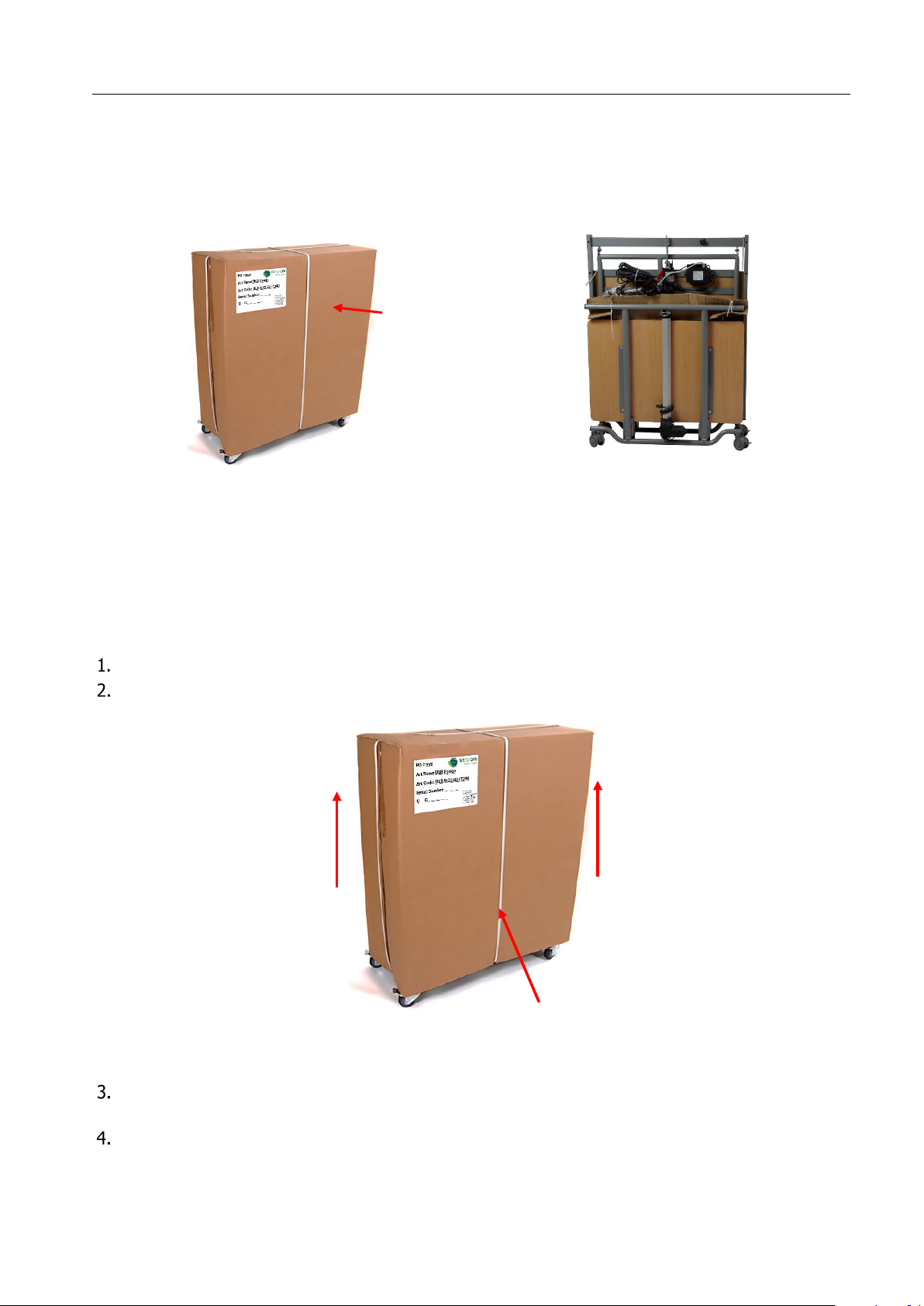
Instruction manual DESCEND
As-received condition
Care bed in the transport device
Shipping carton
2
1
_______________________________________
4 Storage and transport
Due to the modular design of the care bed, transport can be carried out effortlessly. This is made
possible by a transport device. The care bed integrated in the transport frame can be manoeuvred in the
narrowest space by means of the bed rollers.
g
in
n
io
s
is
m
m
o
c
d
n
a
bly
m
e
s
s
A
5
5.1 Removal from the transport device
On receipt of the delivery and before assembly, check whether the packaging is damaged. Complain any
visible damage immediately to the delivering company.
Cut the packaging tapes with a side cutter or scissors.
Lift the transport carton from the entire bed unit including the transport device.
P
l
eas
stored in the transport frame.
Last update:11.10.2022
T
h
e
do
not
d
is
pos
e
of
t
he
c
ov
For removal from the transport device, the Descend must be stationary, i.e. the four individual
brakes on the wheels must be stationary.
First lift the lying surface half for the foot end
(b)
out of the transport device.
Page 12 of 40
er!
is
c
a
n
b
e
r
e
u
s
ed
a
s
(a)
and then the lying surface half for the head end
d
u
s
t
pr
o
t
e
cti
on
wh
e
n
the
c
a
re
b
e
d
i
s
la
t
e
r
Page 13
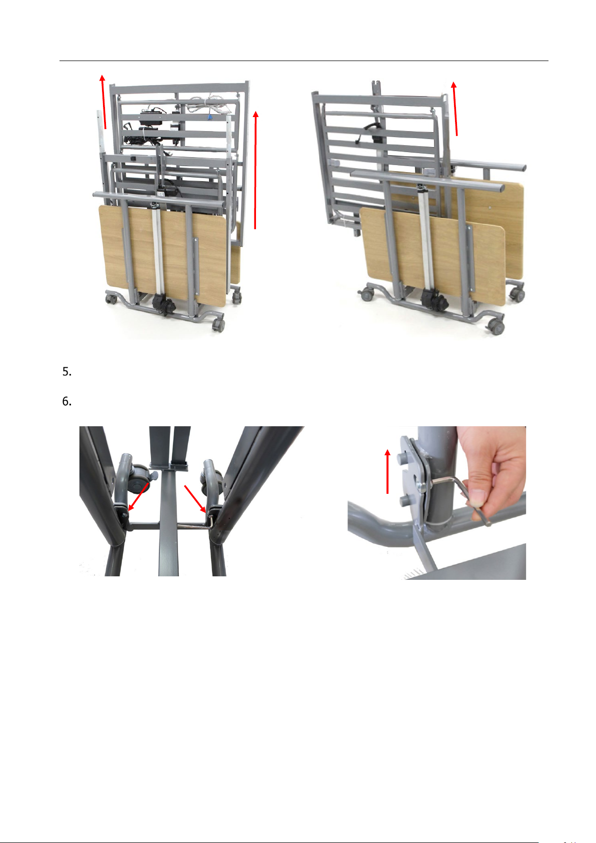
Instruction manual DESCEND
_______________________________________
(
Lying surface half for the foot end
a
)
c
i
v
e
d
t
r
o
p
s
n
a
tr
e
th
om
r
f
s
d
a
e
t
s
d
e
b
th
o
b
e
v
o
m
e
R
(b)
Lying surface half for the head end
g
n
ti
c
e
n
on
c
e
th
n
o
s
w
e
r
c
s
n
e
l
l
A
4
e
h
t
n
e
s
o
o
L
.
e
straps and unhook them.
The Allen screws are needed again for the assembly of the lying surface with the bed control parts!
Last update:11.10.2022
Page 13 of 40
Page 14
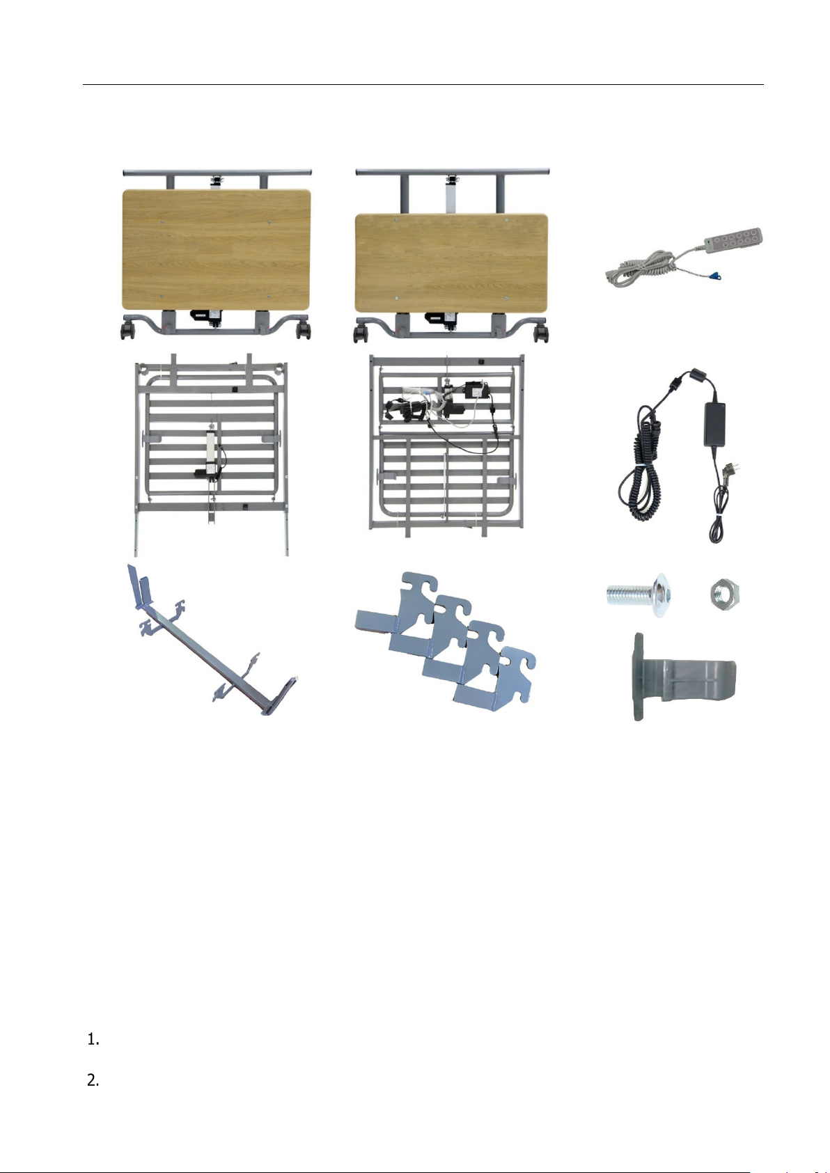
Instruction manual DESCEND
_______________________________________
5.2 Control of the delivery and the scope of delivery
After unpacking and removal from the transport device, please check that the delivery is complete. The
following parts are included in the scope of delivery:
1 2 3
4
7
5
8
6
9
10
1 Bed control unit head side 1x 6 Power supply unit with mains plug 1x
2 Bed control unit foot side 1x 7 Transport device 1x
3 H
an
d
c
o
n
t
r
o
l
wi
t
h
n
u
r
s
e
k
e
y
1x
8 C
o
n
n
e
ct
i
n
g
p
i
e
ce
s
4
x
4 Lying surface half head side 1x 9 Allen screw 12x and nuts 4x
5 Lying surface half foot side 1x 10 Mattress holder 4x
11 Instruction manual 1x (without illustration)
5.3 Assembling the Descend
Proceed as follows to assemble the Descend:
Place the two halves of the lying surface (head and foot side) on the floor with the upper side facing
downwards.
Push the two lying surface connectors already mounted on the lying surface half of the head side
into the frame openings of the lying surface half of the foot side.
Last update:11.10.2022
Page 14 of 40
Page 15
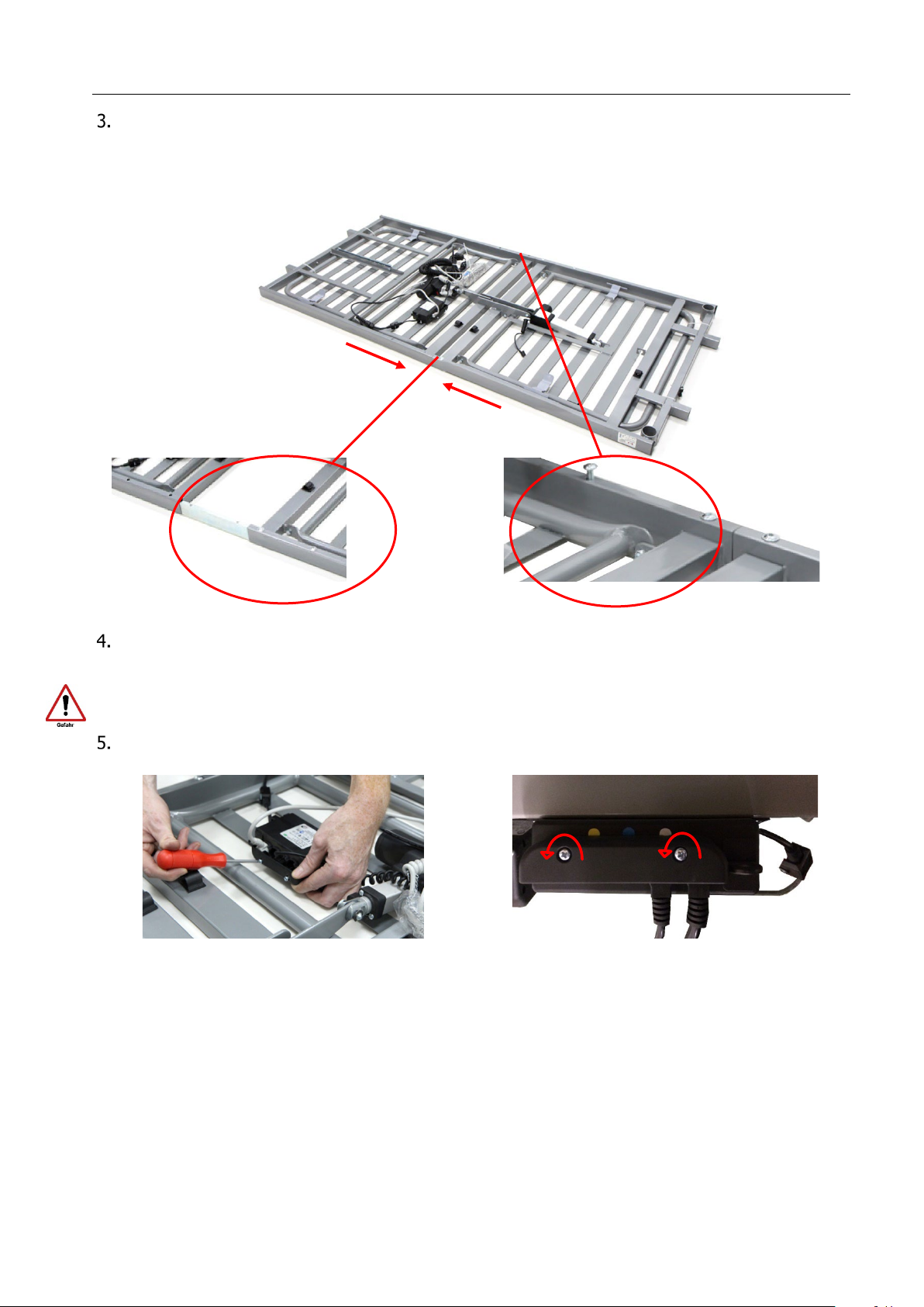
Instruction manual DESCEND
L
y
i
ng
s
ur
fa
c
e
c
o
nn
e
c
t
o
r
_______________________________________
r,
e
h
t
o
h
c
a
e
o
t
n
i
d
e
h
s
u
p
y
l
e
t
e
l
p
m
o
c
e
r
a
s
e
v
l
a
h
e
c
a
rf
u
s
g
n
i
y
l
h
t
o
b
n
e
h
W
the 4 holes on the frame of the lying surface half of the foot side.
Check that the 4 Allen screws are tight on the lying surface half of the head side.
o
t
n
i
ws
e
r
c
s
n
e
l
l
A
e
h
t
w
e
r
c
s
Disconnect the cable ties that attach the power supply unit and the hand control to the lying surface.
The electrical cables must not be damaged when the cable ties are cut.
Remove the cover from the control unit by loosening both screws.
Last update:11.10.2022
Page 15 of 40
Page 16
Instruction manual DESCEND
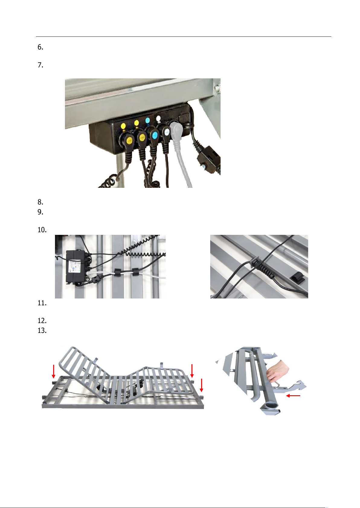
1 Height adjustment drive
1
2
3 4 5
_______________________________________
e
y
d
e
k
r
a
m
(
s
t
r
a
p
l
o
r
t
n
o
c
d
e
b
e
h
t
f
o
s
e
v
i
dr
t
n
e
m
t
s
u
dj
a
t
h
g
i
e
h
e
h
t
f
o
gs
u
pl
o
w
t
e
h
t
t
c
e
n
n
o
C
the plug of the backrest adjustment drive (marked white) to the control unit.
The plug for the thigh adjustment drive (marked blue) and the plug for the hand switch are already
plugged into the control unit at the factory.
iv
dr
t
n
e
m
t
s
u
dj
a
ht
g
i
e
H
2
3 Thigh adjustment drive
d
nt
e
m
t
us
j
d
a
t
s
e
r
k
c
a
B
4
l
o
r
nt
o
c
nd
a
H
5
d
n
a
)
w
o
l
l
e
e
v
i
r
Replace the cover plate on the control unit by screwing in both screws.
Fix the cable of the hand control and the mains cable to the underside of the lying surface using the
tabs provided.
Fasten the strain relief of the mains cable in the holder at the head end.
Carefully turn the lying surface over so that the drives point downwards to the floor. Do not damage
the control unit or the drives.
Use a side cutter or knife to remove the cable ties that fix the lying surface to the frame.
.
s
w
e
r
c
s
n
e
l
l
A
o
tw
th
i
w
h
c
a
e
n
te
s
a
f
d
n
a
s
g
n
i
n
e
p
o
e
m
a
r
f
t
on
r
f
e
th
to
n
i
s
p
a
tr
s
g
n
ti
c
e
n
con
e
th
t
r
e
s
n
I
Last update:11.10.2022
Page 16 of 40
Page 17
Instruction manual DESCEND
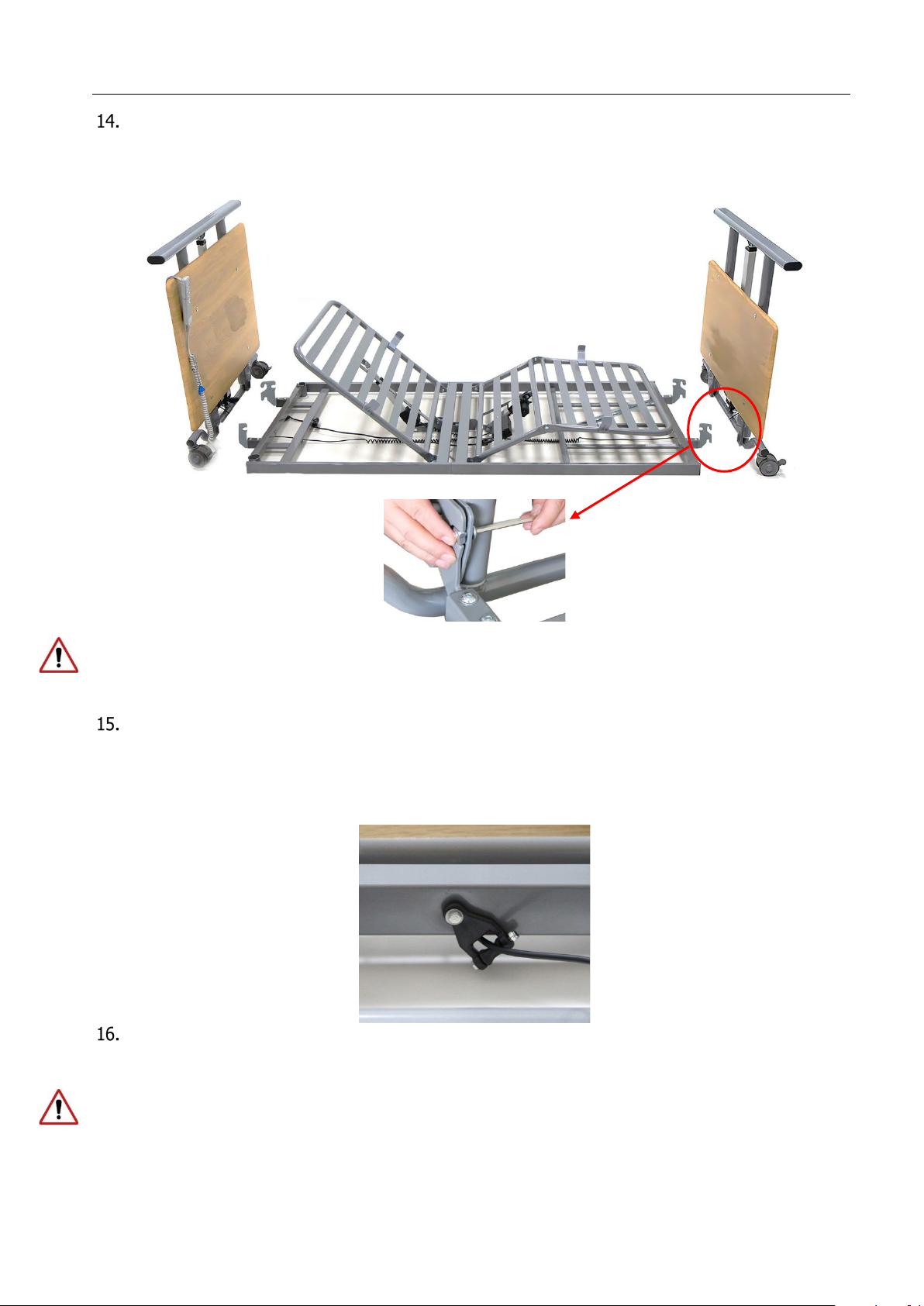
control for the foot side to the lying surface end of the thigh rest.
Make sure that the power cord is positioned so that it cannot be crushed or damaged by driving over it.
_______________________________________
m
e
s
s
a
y
l
s
u
o
i
v
e
pr
e
h
t
k
oo
h
,
s
i
th
o
d
o
T
.
ts
r
a
p
ol
tr
on
c
d
e
b
e
th
to
e
c
a
f
r
u
s
g
n
i
y
l
e
th
t
c
e
n
on
C
connecting straps into the locating pins on the bed control elements. Then fasten the connections
with one Allen screw and one nut each.
bl
d
e
Be sure to mount the bed control for the head side to the lying surface end of the backrest and the bed
At the front side of the lying surface frame there is a cable guide at the head and foot side to hold
and protect the cables of the height adjustment drives.
To be able to guide the cables through the cable guide, you must loosen the reel on the cable guide
l
e
e
r
e
h
t
n
e
t
s
a
f
d
n
a
e
v
ri
d
t
n
e
m
t
s
u
j
d
a
t
h
g
i
e
h
e
h
t
f
o
e
l
b
a
c
e
h
t
rt
e
s
n
i
,
)
m
7m
(
s
r
e
n
n
a
p
s
g
n
ri
wo
t
h
t
i
w
.
n
i
a
g
a
Position the Descend care bed in the desired position in the room and plug the mains plug into the
socket.
The mains plug must always be accessible so that in an emergency the system can be disconnected
from the mains supply by pulling it out of the socket.
Last update:11.10.2022
Page 17 of 40
Page 18
Instruction manual DESCEND
P
r
o
d
u
c
ti
on
m
on
t
h
P
ro
d
u
c
t
i
o
n
y
e
a
r
Plug together
Engage the snap-in cylinder pin
in the recess
Erector admission
_______________________________________
5.4 Erector with triangle handle (accessory)
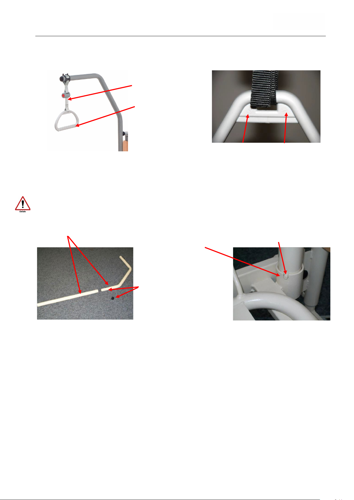
With the help of the erector, the patient can stand up and move more easily into another position. A
triangle handle is attached to the erector.
Belt strap with buckle
for adjusting the length
T
riangle handle
Mount the erecting bracket and insert it into the erecting fixture in the lying surface. Make sure that the
.
e
r
u
t
x
fi
g
n
i
t
ec
r
e
e
h
t
f
o
s
es
ec
r
e
h
t
n
i
s
e
g
a
g
n
e
n
i
p
r
e
d
n
i
l
y
c
g
n
i
k
c
o
l
Attention: The erecting bracket must not be used outside the latching mechanism.
rew the star grip screw into
Sc
the threaded hole and
tighten.
The length of the strap of the triangle handle can be adjusted by the buckle. Select an adjustment that
a
l
l
o
ws
t
h
e
u
s
e
r
t
o
e
a
s
i
l
y
re
a
c
h
t
h
e
h
a
n
d
l
e
wh
e
n
l
y
i
n
g
d
o
wn
(u
s
u
a
l
l
y
b
e
t
we
e
n
55
-
7
0
c
m
m
ea
s
u
r
ed
fr
o
m
the upper edge of the mattress).
Make sure that the belt is securely fastened again.
The triangle handle has a shelf life of at least 5 years under normal use (see embossing of production
date). It is then recommended to replace the triangle handle.
lide the fixed loop of the triangle belt over the first bolt of the erector and check its secure hold by
S
pulling the triangle handle firmly downwards.
Last update:11.10.2022
Page 18 of 40
Page 19
Instruction manual DESCEND
A
tte
n
ti
on
:
F
i
x
th
e
l
o
op
o
f
th
e
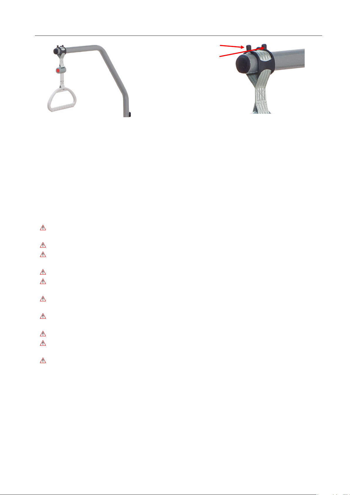
_______________________________________
triangle belt only between
these two bolts!
5.5 Foldable side rails (accessories- item number BC 1.19.0270000)
Prius Healthcare side rails are available as accessories for the Descend nursing beds.
The intended use of the side rails is the installation exclusively on the Descend. The use of the
optional side rails reduces the risk of the patient falling out of the Descend unintentionally. The
side rails are not designed to prevent the patient from leaving the bed intentionally.
Any other use is considered improper and is excluded from possible liability.
5.5.1 Safety instructions when using the steel side rails
Only use side rails approved by Prius Healthcare as optional accessories
(item number BC 1.19.0270000).
The use of incompatible side rails is not permitted and can lead to hazards, e.g. due to trapping.
The distance between two side rails lying one above the other or between the lower edge of the
lower side rail and the lying surface must not exceed 12 cm.
Only instructed personnel may assemble/disassemble the side rails.
When using the side rails, their suitability must be assessed by the attending physician or a nurse,
considering the individual needs and abilities of the patient.
During operation of the adjustment functions of the nursing bed, no parts of the patient's body
may protrude over the lying surface or touch the side rails.
The side rails only offer protection against rolling out when the backrest and knee adjustment are
in the horizontal position.
Under no circumstances should side rails be used improperly (e.g. for climbing over or supporting).
The distance between the top edge of the side rail and the top of the mattress in non-compressed
condition must be at least 22 cm.
When using side rails, there is an increased risk of crushing and clamping.
Last update:11.10.2022
Page 19 of 40
Page 20
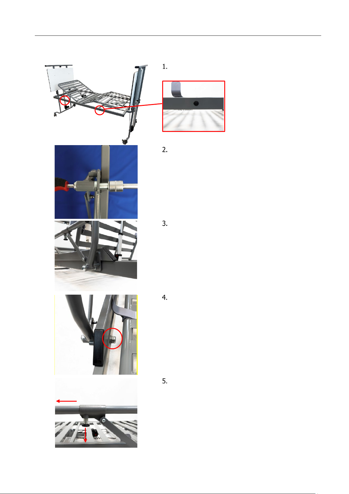
Instruction manual DESCEND
Place the side rail on the bed frame tube so that the
Tighten the nuts again
To fold in the side rail, pull on the locking bolt
_______________________________________
5.5.2 Assembly of the steel-side rails
Proceed as follows to install the steel side rails:
Remove the black caps from the pre-drilled holes on
the bed frame of the Descend.
Loosen the nuts on the side rail.
s
c
r
e
w
s
f
i
t
i
n
to
th
e
e
x
i
s
ti
n
g
h
ol
e
s
.
It is easier if you remove the mattress first and put the
head- and footrest up)
Last update:11.10.2022
Page 20 of 40
Page 21
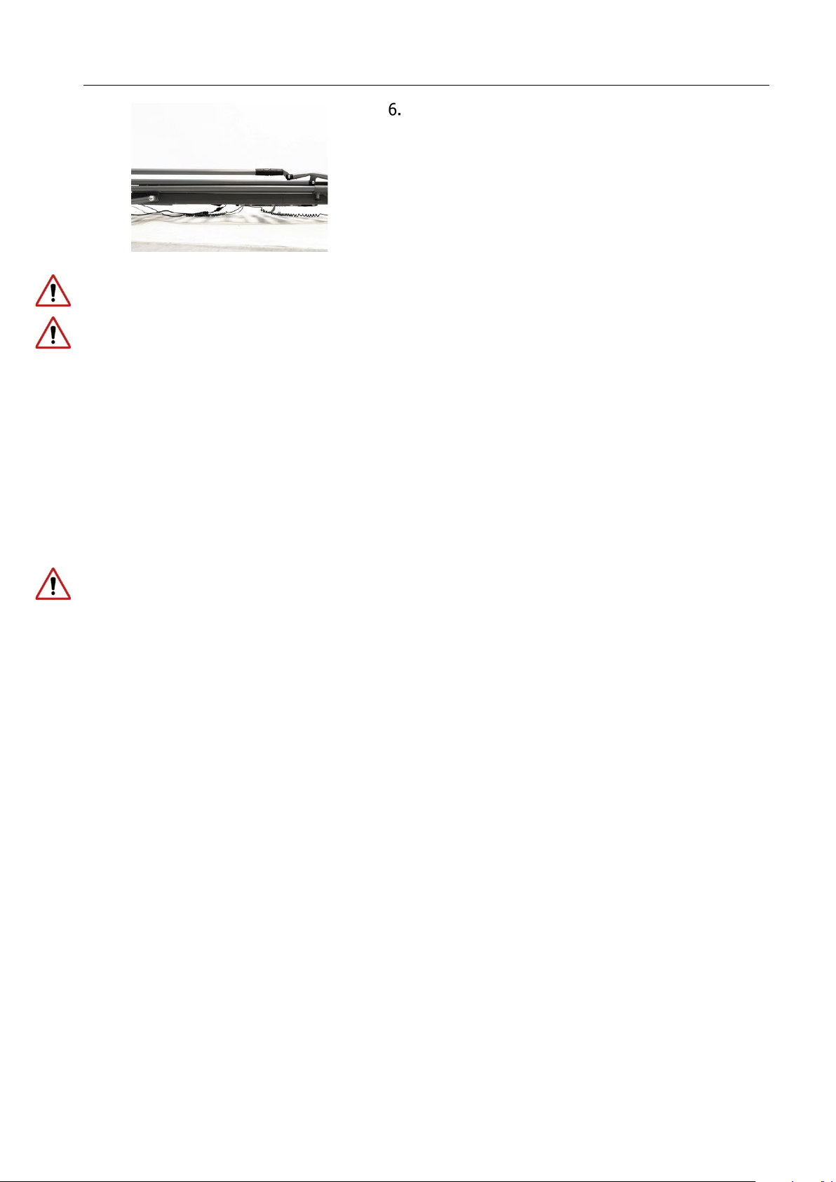
Instruction manual DESCEND
P
u
s
h
t
h
e
s
i
d
e
r
a
i
l
w
i
t
h
t
h
e
u
n
l
o
c
k
e
d
bo
l
t
s
t
o
t
h
e
s
i
d
e
_______________________________________
until it is completely folded in.
After installing the side rails, check that they are securely attached to the mattress base frame.
After folding up the side rail, the locking bolt must be fully engaged again. Check the strength of the
folded up side rail.
5.6 Commissioning
The Descend care bed is ready for operation after it has been successfully carried out and all steps from
chapter 5, paras. 5.3 and 5.5 have been observed. Once the Descend has been installed, carry out a
check in accordance with Chapter 9, Section 9.2.
Clean and disinfect the bed before using it for the first time and before each use according to chapter 7.
Place your mattress on the lying surface of your Descend. The mattress dimensions must correspond to
the dimensions of the lying surface.
Connect the mains plug into the mains socket.
The mains plug must always be accessible so that in an emergency the system can be disconnected
from the mains supply by pulling it out of the socket.
Make sure that the power cord is not crushed or driven over.
The Descend nursing bed can now be used.
5.7 Disassembling the Descend care bed
Always disconnect the mains plug from the socket before dismantling!
Disassembly of the care bed is carried out in reverse order to the assembly.
Last update:11.10.2022
Page 21 of 40
Page 22

Instruction manual DESCEND
1
Bed control unit on the head side with integrated height
adjustment drive
2
Be
d
c
on
tr
ol
u
n
i
t
on
th
e
f
oo
t
s
i
d
e
w
i
t
h
i
n
t
e
g
r
a
te
d
h
e
i
g
h
t
a
dj
u
s
t
m
e
n
t
dr
iv
e
3
Electrically adjustable backrest
4
Electrically adjustable thigh support
5
Mechanically adjustable lower leg support
6
H
a
n
d
c
o
n
t
ro
l
w
i
t
h
n
u
rs
e
k
e
y
7
Electric drive for backrest
8
Electric drive for thigh support
9
Mechanical latching mechanism for adjusting the lower leg
support
10
Electric height adjustment drive for the head side
11
Electric height adjustment drive on foot side
12
P
o
w
e
r
s
u
ppl
y
u
n
i
t
w
i
t
h
S
M
P
S
,
m
a
i
n
s
c
a
bl
e
a
n
d
m
a
i
n
s
p
l
u
g
13
Mattress holder
14
Tube holder for erecting bracket (on both sides)
15
M
e
c
h
a
n
i
c
a
l
l
y
l
o
c
k
a
bl
e
t
r
a
c
k
r
o
l
l
e
r
16
Control unit
1 2 3 4 5
6
7
8
9
10
11
13
14
15
16
12
_______________________________________
6 Functional description
6.1 Technical overview of the Descend
Last update:11.10.2022
Page 22 of 40
Page 23
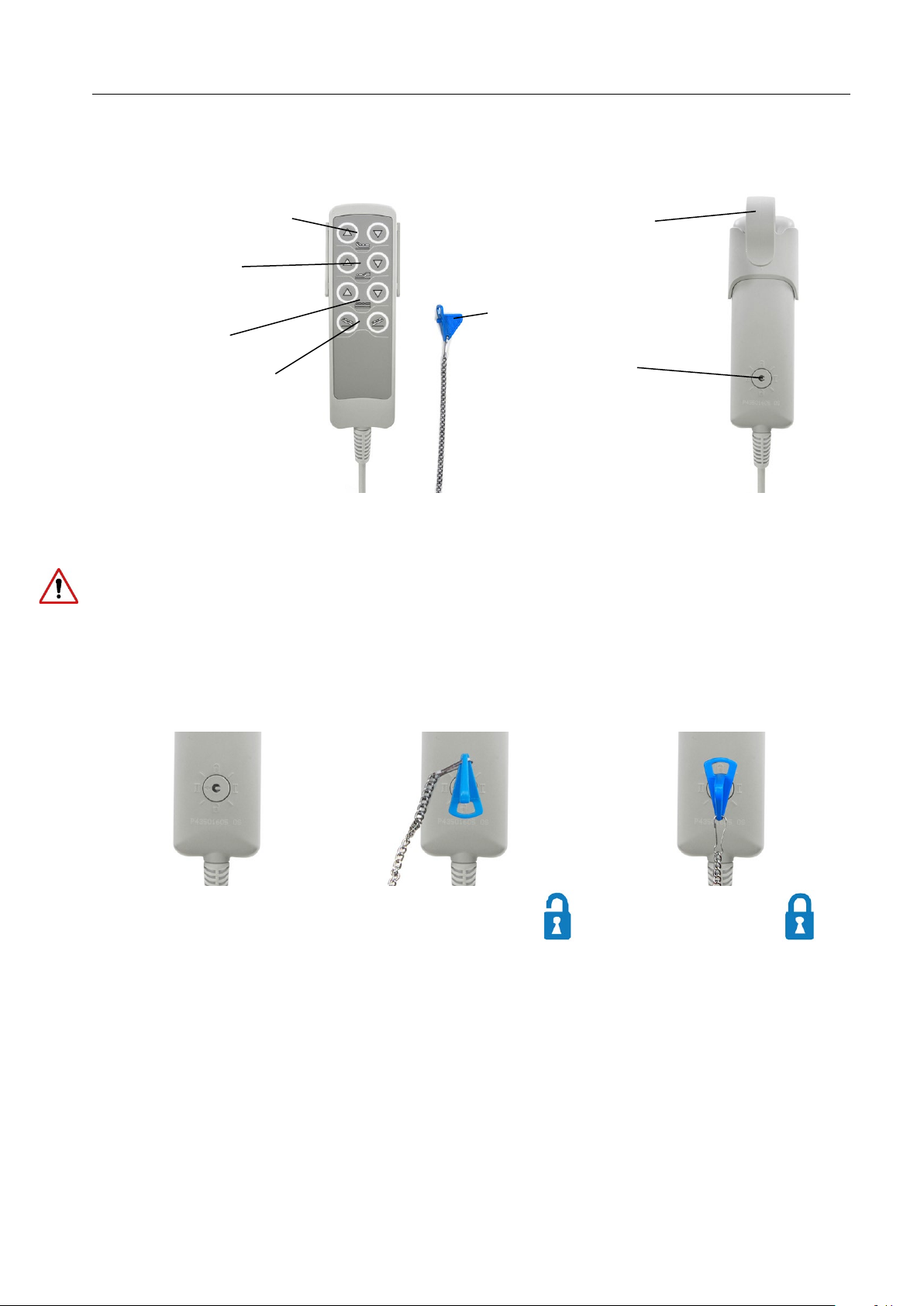
Instruction manual DESCEND
Lower leg section
Lying surface
Nurse key
T
re
n
d
e
l
e
n
b
u
rg
- /
A
nt
i
L
oc
k
f
or
All electrical
active
All electrical
disabled
_______________________________________
6.2 Hand control with locking function
The electric bed functions can be operated via the handset. All functions can be locked with the nurse
key.
Backrest adjustment
n
w
o
d
/
up
Hand control hook
up/down
up/down
-
Trendelenburg function
Activating/deactivating
the handset function
n order to avoid damage, the hand control should always be suspended from the hand control hook
I
)
t
i
n
u
l
ro
t
n
o
c
d
e
b
.
g
.
(e
.
e
s
u
n
i
t
o
n
n
e
wh
m.
e
st
sy
e
h
t
e
g
ma
a
d
d
n
a
d
a
o
l
r
e
v
o
y
ma
s
i
h
t
s
a
me
i
t
me
a
s
e
h
t
t
a
s
y
e
k
e
l
p
i
t
l
mu
s
s
e
r
p
t
o
n
Do
6.3 Locking function for handset
There is a lock on the back of the hand control. All electrical adjustment functions can be locked
simultaneously by turning the enclosed nurse key in the lock.
m
t
us
j
d
a
m
t
us
j
d
a
n
u
f
nt
e
n
u
f
nt
e
ns
o
i
t
c
ns
o
i
t
c
Switching positions I and II are test positions used to check safety during regular safety checks or after
repair work.
Last update:11.10.2022
Page 23 of 40
Page 24
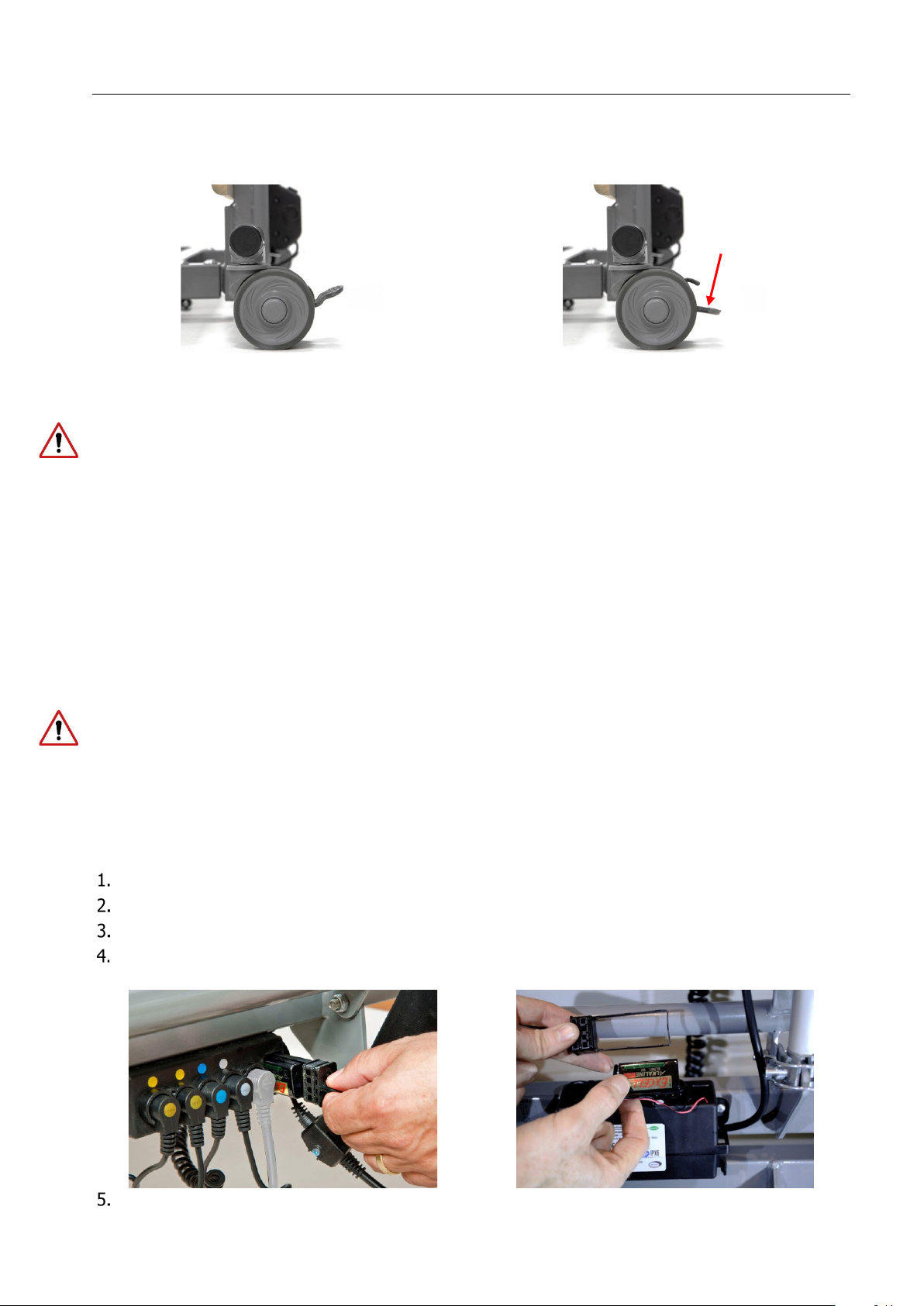
Instruction manual DESCEND
Released brake
Lock the brake with your foot.
See also safety instructions!
However, the 9V battery should be replaced every 2 years even if not in use.
_______________________________________
6.4 Operation of the lockable track rollers
All rollers of the bed can be locked individually and must always be locked during normal operation. This
is total locking, i.e. directional locking and simultaneous braking of the roller.
!
d
e
b
e
th
e
v
o
m
to
d
e
s
a
e
l
e
r
e
b
y
l
on
y
a
m
s
e
k
a
r
b
e
h
T
:
on
ti
n
tte
A
g
n
eri
w
o
l
y
c
merg
E
5
.
6
en
6.5.1 Emergency lowering via integrated 9V battery (electric)
The control unit mounted on the lying surface is equipped with a 9V block battery, which enables the
individual electrical adjustment functions to be lowered in the event of a mains power failure. If the
mains power should fail, you have the option of returning the electric drives to their lowest position.
Please note that this is only possible once per 9V battery, as the capacity of the 9V battery is very
limited.
After using the emergency lowering once, the 9V battery must be replaced with a new equivalent one
(alkaline manganese battery type 6LR61).
ge
an
h
c
y
r
e
t
at
B
2
.
5
.
6
To replace, check or remove the 9V battery for longer storage, the battery compartment of the control
.
d
e
n
e
op
e
b
t
s
u
m
t
i
n
u
Disconnect the mains plug!
s.
w
e
r
sc
d
a
e
h
s
s
ro
c
wo
t
e
h
t
g
n
i
w
e
r
c
s
n
u
y
b
t
i
n
u
l
ro
t
n
o
c
e
h
t
n
o
r
e
v
o
c
e
h
t
e
v
o
m
e
R
.
y
r
tte
a
b
V
9
e
th
th
i
w
r
e
h
t
e
g
to
r
e
v
o
c
e
th
t
ou
l
l
u
P
Disconnect the battery from the battery clip and replace it with a new equivalent battery of the type
"alkaline manganese battery type 6LR61".
Slide the cover with the new 9V battery back into the opening of the control unit. Make sure that the
seal is not damaged.
Last update:11.10.2022
Page 24 of 40
Page 25
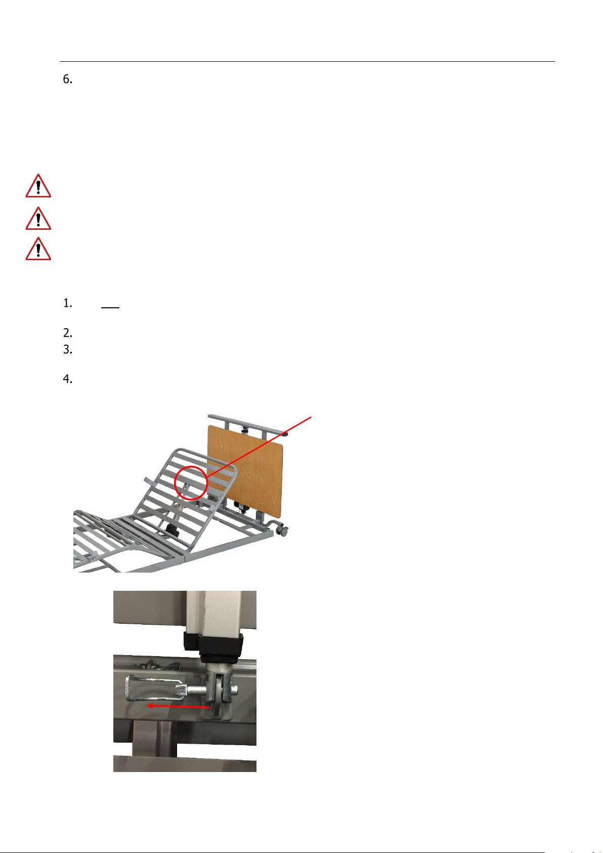
Instruction manual DESCEND
from the backrest and thus to serious injuries for the user and the patient!
s
e
v
e
ra
l
t
i
m
e
s
u
n
d
e
r
n
o
r
m
a
l
c
o
n
d
i
t
i
o
n
s
i
n
o
rd
e
r
t
o
b
e
a
b
l
e
t
o
l
o
w
er
t
h
e
b
a
c
k
r
e
s
t
s
a
f
el
y
i
n
a
n
e
m
er
g
e
n
c
y
.
Loosen this socket pin on the backrest drive for
Open the safety clip on the socket pin and pull
_______________________________________
t
o
n
e
r
a
s
w
e
r
c
s
e
th
t
a
th
e
r
u
s
e
k
a
M
.
s
w
e
r
c
s
th
o
b
th
i
w
t
i
n
u
l
o
tr
on
c
e
th
to
r
e
v
o
c
e
h
t
en
t
s
fa
y
l
l
a
n
i
F
overtightened during tightening.
6.5.3 Emergency lowering of the backrest (manual)
If the backrest must be lowered in less than 30 seconds in the event of a power failure or the Descend
electric drive system has failed, you can lower the backrest manually.
Observe these safety and implementation instructions, as non-compliance can lead to uncontrolled falls
Always carry out the emergency lowering of the backrest by hand with two users!
Manual emergency lowering may only be carried out by instructed users and should be practised
:
ng
i
er
ow
l
y
enc
g
er
em
l
a
c
ni
ha
ec
m
of
on
i
t
u
ec
x
E
The first user relieves the backrest before the emergency lowering by lifting the frame and holding it
in this position. If necessary, the second user supports this procedure.
The second user unfolds the bent safety clip of the socket pin at the head end of the backrest drive.
Then he pulls the socket pin out of the lifting rod. The drive is now separated from the backrest and
swivels downwards.
Both users lower the backrest slowly and in a controlled manner.
manual emergency lowering.
out the socket pin.
Last update:11.10.2022
Page 25 of 40
Page 26
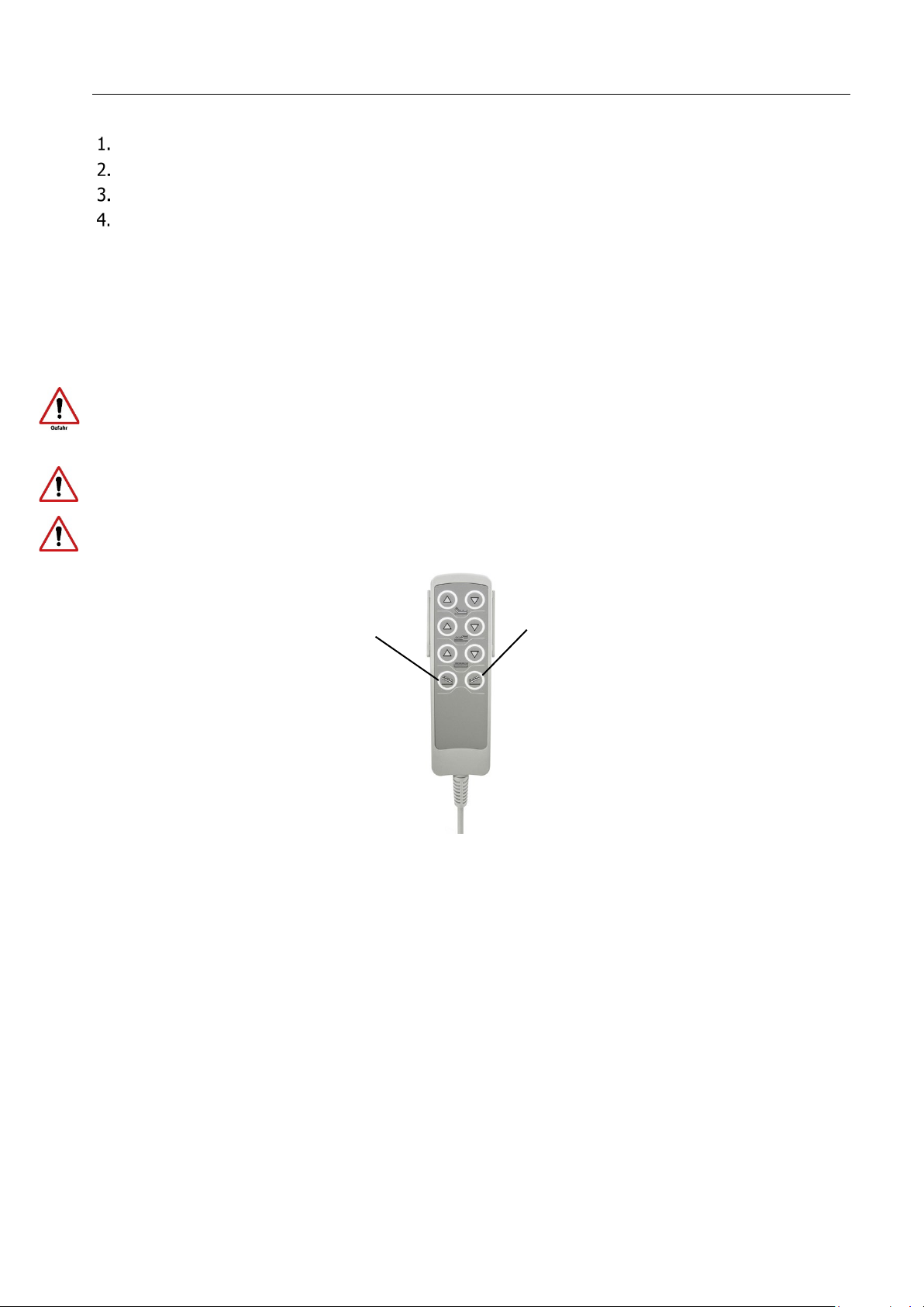
Instruction manual DESCEND
_______________________________________
Restoration of the original condition:
Swivel the lifting rod of the drive up again in the direction of the backrest.
.
e
m
a
r
f
d
e
b
e
th
d
n
a
od
r
g
n
ti
f
i
l
e
th
f
o
g
n
ti
n
u
o
m
e
th
to
n
i
n
i
p
t
e
k
c
o
s
e
th
t
r
e
s
n
I
Make sure to reinsert the socket pin from the operator side so that it is always accessible.
.
n
pi
t
e
k
c
o
s
e
h
t
n
o
p
i
l
c
y
et
f
a
s
e
h
t
e
s
o
l
C
6.6 Trendelenburg / Reverse Trendelenburg function (option)
As an option, the Descend nursing bed can be equipped with Trendelenburg or Reverse
Trendelenburg bearings.
Wit
h Trendelenburg bedding, the lying surface of the nursing bed is inclined in the headroom
bedding. With Reverse Trendelenburg positioning, the lying surface is inclined to the low foot position.
Trendelenburg positioning may only be used at the instigation of a doctor, as it can
influence the clinical condition of the patient.
Do not leave the patient unattended during Trendelenburg or Reverse Trendelenburg positioning.
Lock the Trendelenburg function when using the care bed in application environment 4 (home
care).
g
r
u
b
n
e
l
e
d
n
e
r
t
i
t
n
A
r
fo
n
o
t
t
u
b
-
h
s
u
P
function (inclination of the lying
n
o
i
t
i
s
o
p
t
o
fo
w
o
l
e
h
t
o
t
e
c
fa
r
u
s
)
sh-button for Trendelenburg function
u
P
(inclination of the lying surface to the head
low position)
Last update:11.10.2022
Page 26 of 40
Page 27

Instruction manual DESCEND
_______________________________________
7 Care, cleaning and disinfection
Clean and disinfect the Descend care bed before using it for the first time and before using it again. For
cleaning, wipe the bed by hand with a damp cloth. We recommend suitable cleaning and care products
as cleaning agents for wooden and plastic furniture.
Household cleaners without ammonia and scouring agents are also permitted but should be
dermatologically tested.
Solvents and scouring agents are not permitted as they attack and damage the various surfaces of the
care bed.
For disinfection:
Indication:
In order to achieve effective disinfection, the nursing bed must be cleaned beforehand.
Disinfection is possible by spray or wipe disinfection with commercially available disinfectants. Do not use
disinfectants containing chlorine as they can have a corrosive effect on metals, plastics etc. and are not
environmentally friendly.
For wipe disinfection (surface disinfection) we recommend approved disinfectants and disinfection
procedures from the list of disinfectants and disinfection procedures tested and approved by the Robert
Koch Institute (https://www.rki.de) or from the VAH disinfectant list (Verbund für Angewandte Hygiene
e.V. / https://vah-online.de).
Bef
or
e
c
l
ea
ni
ng
a
nd
d
i
s
i
nf
e
c
t
i
on
,
t
he
m
a
i
ns
p
l
ug
m
us
t
b
e
d
i
s
c
onnec
securely suspended. The plug for the handset and the motors, which are plugged into t
c
ontrol at the lying surface drive, must be plugged in. This is necessary so that no water
t
ed
f
r
om
t
he
m
a
i
n
s
he
can penetrate the control unit.
The electrical components must not be sprayed with a high-pressure cleaner or water jet. Only wipe
d.
e
t
t
i
m
r
e
p
is
n
o
i
t
c
e
f
n
i
s
di
an
d
Last update:11.10.2022
Page 27 of 40
Page 28
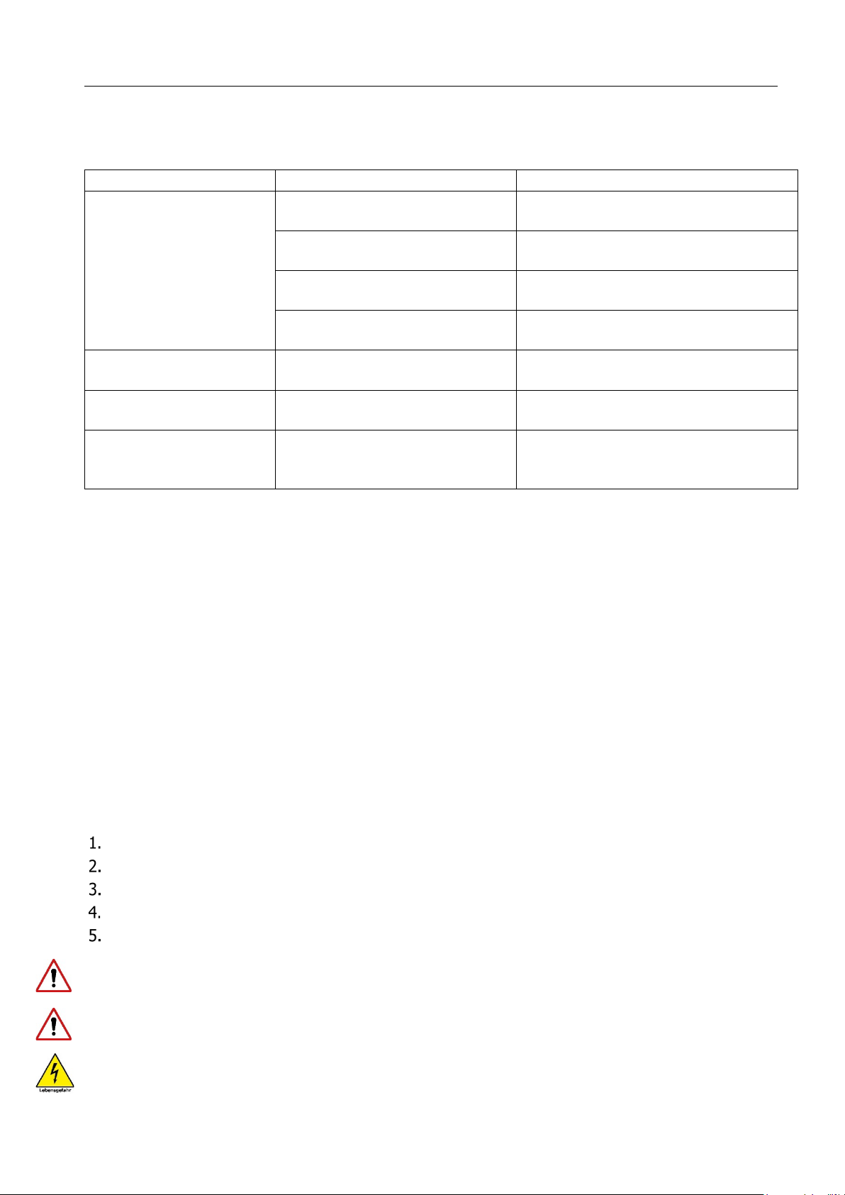
Instruction manual DESCEND
Malfunction
Possible cause
Remedy
No function of the drives
Mains plug not connected
Connect mains plug
Lock function on hand control
a
c
t
i
v
at
e
d
Unlock the hand control.
Ha
n
d
c
on
tr
o
l
n
o
t
pl
u
gg
e
d
i
n
I
n
s
e
rt
t
h
e
h
a
n
d
c
on
tr
o
l
i
n
t
o
th
e
con
tr
o
l
unit.
Drive not plugged in
Plug the drive into the control unit.
Reversed adjustment
f
u
n
c
t
i
o
n
s
Connection cable on the
c
o
n
n
e
c
t
o
rs
r
e
v
e
rs
e
d
Check plugs and connectors and
re
i
n
s
e
rt
.
No f
u
n
c
t
i
o
n
a
f
t
e
r
p
o
we
r
f
a
i
l
ur
e
9
V
b
l
oc
k
b
a
tte
r
y
i
s
e
m
p
ty
R
e
p
l
a
c
e
9
V
b
l
o
c
k
b
a
t
t
e
r
y
Bed moves very slowly
Bed can only be adjusted via
battery. Mains plug not
plugged in
Plug in the mains plug and replace the
9V block battery preventively.
below, the bed must never be put back into operation. Then contact the supplier or manufacturer.
is in use and the patient is in it.
be replaced by qualified personnel.
_______________________________________
8 Cause and remedy of malfunctions
Not every malfunction is directly attributable to a defect in the nursing bed. Before contacting
your dealer or Prius Healthcare, please check the malfunction using the table below.
e
nc
na
e
nt
i
a
M
9
9.1 Fundamentals
In accordance with MPBetreibV §7 (as of 2021), operators of care beds are obliged to ensure the safe
and proper operation of the medical device on an ongoing basis by means of maintenance measures
(inspection and maintenance).
e
f
a
s
e
r
u
s
n
e
o
T
e.
c
n
a
n
e
t
n
i
a
m
d
n
a
g
n
i
l
d
n
a
h
e
h
t
n
o
y
l
l
a
i
t
n
e
s
es
s
d
n
e
p
e
d
d
e
b
e
r
a
c
e
h
t
f
o
e
f
i
l
e
c
i
v
er
s
e
Th
operation, we recommend that a visual and functional check, including an electrical check, be carried out
at least once a year and before each reuse as a guide value. This should be carried out under your own
responsibility and with verifiable compliance with the 2% error rate (see also DGUV regulation 3 §5,
table 1B). If an error rate of <2% is demonstrably achieved during the electrical test, the test cycle can
be extended to a maximum of two years.
Carry out maintenance at least once a year and before each reuse in accordance with the maintenance
schedule and the test regulations in accordance with IEC 62353 in its current version.
The following tests according to IEC 62353 apply to our care beds:
Visual inspection
Leakage current measurement
I
ns
ul
a
t
i
o
n
r
e
s
i
s
t
a
n
c
e
m
e
a
s
ur
e
m
e
nt
Functional test
Overall assessment and documentation
t
ng
i
r
u
d
d
e
b
e
th
of
t
r
pa
y
n
a
f
o
tion
c
n
u
f
r
o
ty
e
f
a
s
e
th
t
bou
a
ts
oub
d
y
an
e
av
h
ou
y
f
I
Maintenance, inspection and repair work are not allowed to be carried out on the nursing bed when it
Electrical components must not be opened and must be replaced. Defective electrical components must
Last update:11.10.2022
Page 28 of 40
d
e
b
cri
s
e
d
rk
o
w
e
h
Page 29
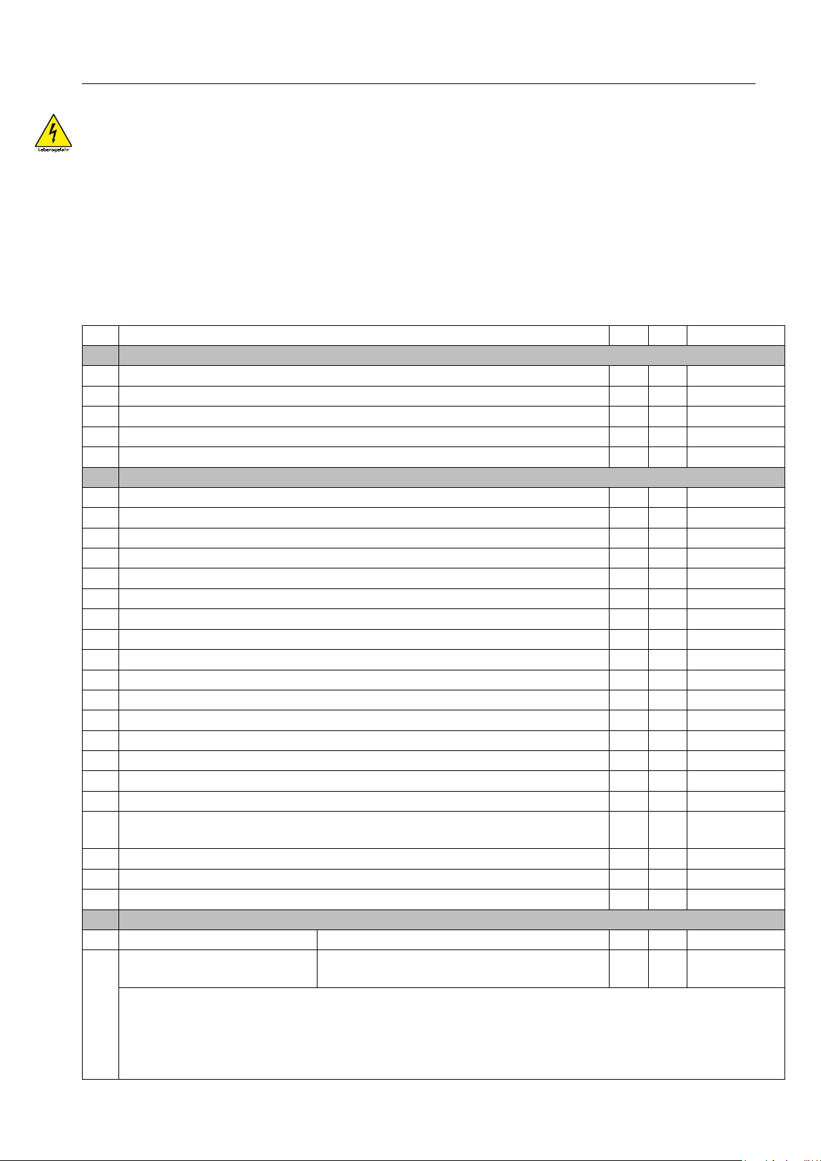
Instruction manual DESCEND
engineering.
Care bed
type
Serial No.:
Location
………………………………
………………………………
Responsible:
Inspector
………………………………
……..
P
os
.
T
e
s
t
i
n
s
tr
u
c
ti
on
OK
Comment
1.
Examination of the basic prerequisite
1.1
Is the general condition okay?
1.2
Type plate of the nursing bed and the electrical components legible?
1.3
Instruction manual available and accessible to personnel?
1.4
Appropriate and safe use?
1.5
W
i
l
l
t
h
e
s
i
d
e
r
ai
l
s
b
e
u
s
e
d
a
ppr
o
pr
i
a
t
e
l
y
?
2.
Visual inspection
2.1
No surface damage or corrosion?
2.2
Mechanical components and welds without defects?
2.3
All mechanical connecting elements are tight?
2.4
Lying surface floor without damage?
2.5
Firm fit and no damage to the head and foot end pieces?
2.6
A
l
l
4
r
o
l
l
e
r
s
u
n
d
a
m
a
g
e
d
a
n
d
t
i
g
h
t
?
2.7
Parking brakes are undamaged and tight?
2.8
E
re
c
t
o
r
w
i
t
h
g
r
a
b
h
a
n
d
l
e
a
n
d
e
r
e
c
t
o
r
h
o
l
d
e
r
u
n
d
a
m
a
g
e
d
a
n
d
n
o
we
a
r?
2.9
Mains cable, connecting cables and plugs without damage?
2.10
Transport protection for mains plug available?
2.11
S
t
r
a
i
n
r
e
l
i
e
f
f
o
r
m
a
i
n
s
c
a
b
l
e
a
n
d
h
a
n
d
s
e
t
s
e
c
u
r
el
y
fa
s
t
en
ed
?
2.12
Are all plug connections firmly plugged in? (sealing rings without damage)
2.13
C
o
r
r
e
c
t
a
n
d
s
a
f
e
c
a
bl
e
l
a
y
i
n
g?
(
n
o
d
a
m
a
g
e
)
2.14
Motor, SMPS power supply and mains plug housings without damage?
2.15
Hand control without damage?
2.16
Th
r
u
s
t
t
u
b
es
o
f
t
h
e
h
ei
g
h
t
a
d
j
u
s
t
m
en
t
d
r
i
v
es
a
r
e
u
n
d
a
m
a
g
ed
?
2.1
Socket pin with safety bracket on backrest drive is freely accessible for
mechanical emergency lowering?
2.18
9V block battery OK / expiration date enough until next test?
2.19
Is the safe working load maintained?
2.20
No surface damage, corrosion or deformities on the side rails?
3
Electrical test according to IEC 62353
3.1
Insulation resistance >7MΩ?
Measured value:
3.2
Device leakage current
<
0
.5m
A
?
Measured value:
The measurement of the device leakage current does not have to be carried out in the normal life
expectancy of the care bed (within the first 10 years) if the
if these care beds are equipped with a drive set from the manufacturer limoss and a power supply unit
(SMPS) from the manufacturer limoss. With these care beds, the incoming mains voltage is converted
into a prote
ctive low voltage of 29V in the power supply unit (SMPS).
_______________________________________
The electrical tests described here in accordance with IEC 62353 may only be carried out by a qualified
electrician or, if suitable measuring and testing equipment is used, by a person trained in electrical
9.2 Maintenance plan
DESCEND
:
:
………………………
n.OK
7
visual and functional test has been passed
Last update:11.10.2022
Page 29 of 40
Page 30

Instruction manual DESCEND
4
Functional test
4.1
All adjustment possibilities of the care bed without obstacles on site?
4.2
Does the locking mechanism for lower leg adjustment work?
4.3
Stress test successfully carried out according to regulations?
4.4
Function test of the handset: correct operation of the keys?
4.5
F
u
n
c
ti
on
te
s
t
o
f
th
e
h
a
n
d
s
e
t
l
oc
k
i
n
g
d
e
v
i
c
e
:
O
n
/
O
f
f
O
K
?
4.
6
C
h
e
c
k
o
f
t
h
e
f
i
rs
t
-e
r
r
o
r
s
a
fe
t
y
b
y
m
ea
n
s
o
f
a
n
i
n
t
e
g
r
a
t
e
d
l
o
c
k
i
n
g
b
o
x
i
n
t
h
e
handset without complaint?
4.7
Track rollers, easily rotatable by 360°?
4.
Wheels, individual parking brakes are functional (enough braking effect
available)?
4.9
W
h
e
n
u
s
i
n
g
t
h
e
s
t
e
e
l
s
i
d
e
r
a
i
l
s
S
i
d
e
r
a
i
l
s
h
e
i
g
h
t
a
b
o
v
e
t
h
e
m
a
ttr
e
s
s
a
t
l
e
a
s
t
2
2
c
m
?
4.10
A
r
e
a
ll
s
c
r
e
w
s
o
n
t
h
e
s
i
d
e
r
a
i
l
(
2
pi
e
c
e
s
p
e
r
s
i
d
e
r
a
i
l
)
pr
e
s
e
n
t
a
n
d
s
c
r
e
w
e
d
tight?
4.11
Locking bolt without damage and fully engages.
Place / Date: ……………………………
Next exam
Inspector: ……………………………
Signature
_______________________________________
8
Overall rating
Overall assessment of the Descend in order?
ervations: ...............................................................................................................
bs
O
.
.
..
.
.
.
..
.
.
..
..
.
..
..
..
..
.
.
.
..
.
.
..
.
.
..
.
..
..
..
..
..
.
.
..
.
.
.
..
.
.
..
.
.
.
..
.
.
..
..
..
..
.
.
.
..
.
.
..
.
.
.
..
..
.
.
..
..
.
..
.
.
..
.
.
..
.
.
..
.
..
..
..
..
..
.
.
..
.
.
.
..
..
..
..
.
..
..
..
..
.
.
..
.
.
..
.
.
.
..
..
.
.
.
..
..
..
.
.
..
.
.
.
..
.
.
..
..
..
.
.
.
..
..
..
..
.
.
.
..
.
.
..
..
..
.
..
..
..
..
..
.
.
..
.
.
.
..
.
.
..
..
.
.
.
..
..
..
: ………………………
: ………………………….
.
.
..
..
..
.
.
.
..
.
.
.
..
.
.
.
..
..
.
Last update:11.10.2022
Page 30 of 40
Page 31
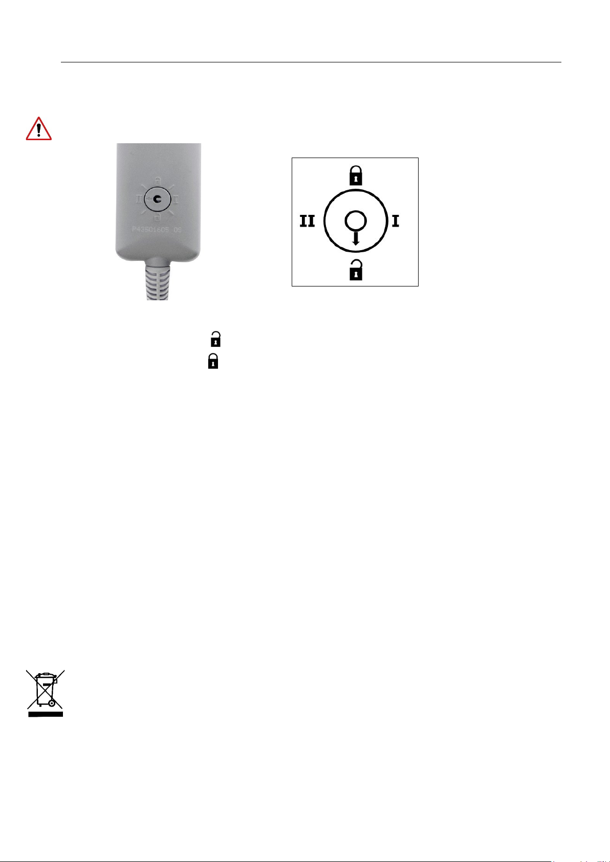
Instruction manual DESCEND
a
n
n
u
a
l
i
n
s
p
e
c
t
i
o
n
o
r
a
f
t
e
r
re
p
a
i
r
o
r
b
ef
o
r
e
e
a
c
h
r
e
-u
s
e
o
f
t
h
e
c
a
r
e
b
e
d
.
_______________________________________
9.3 Check of first-error safety by means of locking function in manual switch
Proceed as follows to check the safety device:
The switching positions I and II are test settings which are used for the safety checks as part of the
:
ts
n
i
o
p
r
ou
f
g
n
i
ow
l
ol
f
e
th
g
n
i
s
u
t
e
s
d
n
a
h
e
th
f
o
k
c
a
b
e
th
on
s
on
ti
i
s
o
p
h
tc
i
w
s
e
th
k
c
e
Ch
•
Switch position adjustment : Move all bed adjustments to a slightly raised position.
•
Setting the switch position : Electrical adjustments must not be possible when the adjustment keys
are pressed.
on
ti
i
s
o
p
t
s
te
to
l
o
tr
on
c
d
n
a
h
k
c
a
b
e
h
S
possible when the adjustment keys are pressed.
•
Move the switch on the back of the handset to test position II: Electrical adjustments must not be
possible when the adjustment keys are pressed.
I
:
i
w
s
e
th
t
e
•
i
r
t
c
e
l
E
t
n
o
h
tc
j
d
a
l
a
c
n
me
st
u
st
mu
s
t
e
th
f
o
b
t
o
n
10 Warranty
Within the scope of our terms of delivery and payment, we guarantee the perfect condition of our care
beds.
a
rk
wo
e
c
n
a
n
e
t
n
i
a
m
t
u
o
d
e
rri
a
c
y
rl
e
p
ro
p
m
i
,
t
c
u
d
ro
p
e
h
t
o
t
s
n
o
i
t
a
c
i
f
i
d
o
m
d
e
s
ri
o
h
t
u
a
n
u
f
o
t
n
e
ev
e
h
t
n
I
.
e
s
p
a
l
l
l
a
h
s
s
m
i
a
l
c
y
t
i
l
i
b
a
i
l
t
c
u
d
ro
p
d
n
a
y
t
n
a
rr
wa
,
e
s
u
r
o
f
s
n
o
i
t
c
ru
t
s
n
i
e
h
t
o
t
ry
a
r
t
n
o
c
e
s
u
l
a
s
o
p
is
d
d
n
a
life
l
fu
e
s
U
11
The service life naturally depends on the way in which the bed is used. With correct operation and
appropriate use, this care bed has an expected service life of 7 to 10 years.
e
d
n
The Descend nursing beds are suitable for re-use in accordance with the measures in chapters 7
and 9. Frequent transport, installation and adjustment reduce the service life just as much as
improper hand
cycles of the electric drives. The healthcare bed must not be disposed
waste at the end of its service life. For environmentally friendly disposal, please contact your local
authority or Prius Healthcare.
The electrical components (power supply units, control units, drives and hand controls) of these
beds are to be treated like electronic waste in accordance with WEEE Directive 2012/19/EU (Waste
Electrical and Electronic Equipment) and disposed of properly.
The components used conform to the directive 2011/65/EU (RoHS II) on the restriction of the use of
certain hazardous substances in electrical and electronic equipment.
Last update:11.10.2022
ling, irregular maintenance and exceeding the safe working load or permissible load
of with normal household
Page 31 of 40
Page 32

Instruction manual DESCEND
S
a
f
e
w
o
r
k
i
n
g
l
o
a
d
(
m
a
x
.
p
e
r
m
i
s
s
i
b
l
e
l
o
a
d)
180kg
I
n
d
i
v
i
d
u
a
l
l
o
a
ds
o
f
t
h
e
s
a
f
e
w
o
r
k
i
n
g
Max
.
p
at
i
e
n
t
w
e
i
g
h
t
170
k
g
Safe erecting load (optional)
80kg
Max. patient weight
170kg
Max. Mattress height
20cm
T
o
t
a
l
l
e
n
gt
h
2170m
m
(
w
i
t
h
2000m
m
l
o
n
g
l
y
i
n
g
s
u
rf
a
c
e
)
Total width
900mm (with 900mm wide lying surface)
H
e
i
g
h
t
o
f
u
p
p
e
r
e
d
g
e
o
f
h
e
a
d
/
f
o
o
t
section
846 – 1419mm
H
e
i
g
ht
a
d
j
us
t
m
e
nt
o
f
l
y
i
n
g
s
ur
f
a
c
e
el
e
c
t
r
i
c
s
t
ep
l
es
s
fr
o
m
6
7
-640mm
B
a
c
k
r
e
st
a
d
j
u
st
me
n
t
e
l
e
c
t
r
i
c
s
t
e
p
l
e
s
s
u
p
t
o
a
p
p
r
o
x
.
70°
Thigh rest adjustment
electric stepless up to approx. 30°
Foot elevation
mechanical, -20°to 0° in 5 steps
Lying surface floor
Steel spring connectors
Individual weights / empty weight
Half of the lying surface head side: 24kg
Track rollers
M
a
t
er
i
a
l
s
f
ra
m
e
,
l
y
i
n
g
s
u
rf
a
c
e
, si
d
e
r
a
i
l
s
et
c
:
s
t
e
el
(
p
o
w
d
er
-c
oa
t
e
d
)
O
p
e
r
a
t
i
n
g
n
o
i
s
e
<
5
3
dB(
A
)
at
1m
Control + power supply SMPS
MC220 + MC125 (Limoss Company)
Hand control:
HC 148
Nominal voltage
230V
Nominal frequency
50/60Hz
C
u
rr
e
n
t
typ
e
AC~
Max. power consumption
2,1 A
Rated recording in idle state
0,5 Watt
Rated operation/nominal rest time
2Min/18Min (max. 5 switching cycles/min)
Primary fuse
2,0 A
Emergency lowering battery
9V block battery (alkaline manganese type 6LR61)
Reclining surface drive back part
1xMD125 (Limoss Company)
Reclining surface drive foot part
1xMD125 (Limoss Company)
_______________________________________
12 Technical specifications
)
al
c
i
an
h
c
e
m
(
a
dat
al
c
i
n
h
c
e
T
1
12.
load
Mattress 200x90x12cm 10kg
kg
al
t
o
T
Half of the lying surface foot side: 23,5kg
Bed control parts: 13kg each
Side rails (optional) per 5kg
Empty weight: 73kg
180
12.2 Technical data (electrical)
Ø 75mm double plastic rollers
Headboard and footboard: wood-based material (veneered)
Electronic components: plastic and aluminum
Last update:11.10.2022
Page 32 of 40
Page 33
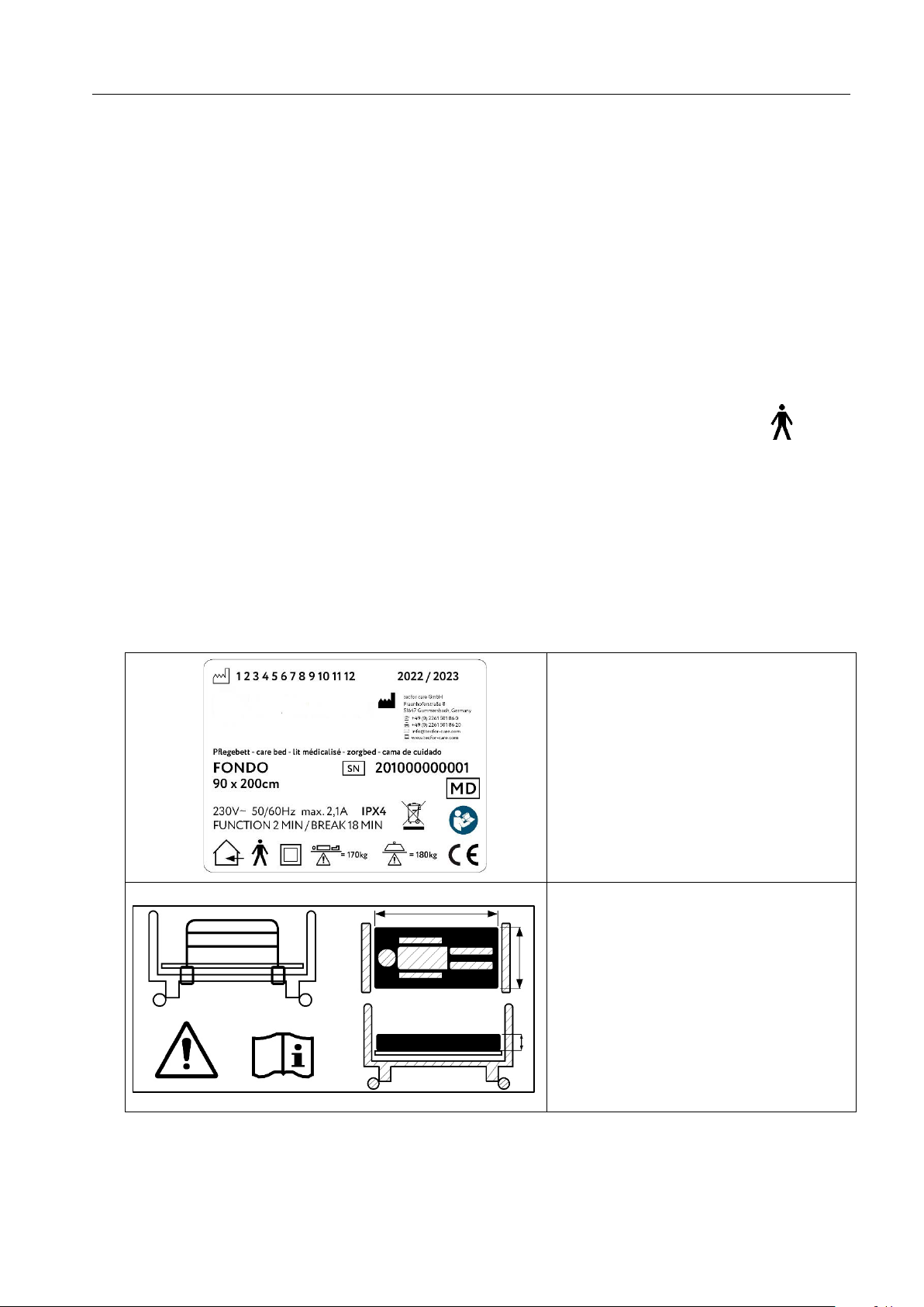
Instruction manual DESCEND
H
e
i
g
h
t
a
dj
u
s
t
m
e
n
t
dr
i
v
e
2
x
M
D1
2
1
(
L
i
mo
ss
C
o
mp
a
n
y
)
Protection class of the drives
IPX4 (protection against splashing water on all sides)
T
e
m
p
er
a
t
u
r
e
r
a
n
g
e
o
p
er
a
t
i
o
n
+
1
0°
C
to
Temperature range storage/transport
-10°C to
Air humidity
30% to 75% rel
Air pressure
between 795 a
Medical device
Class 1
Degree of protection according to IEC 60601-1
Application part of type B
Housing protection class according to IEC 60529
IPX4 (protection against splashing water on
Max. Duty cycle
10%, On 2Min/Off 18Min
M
a
x
.
S
wi
t
c
h
-o
n
cy
cl
e
s
/
m
in
5
S
a
f
e
ty
i
n
s
p
e
c
ti
on
s
1
x
y
e
ar
l
y
I
d
e
n
t
ific
a
t
io
n
p
la
t
e
N
o
t
e
:
_______________________________________
t
men
n
o
r
i
v
en
a
at
d
l
a
c
hni
ec
T
3
12.
n
o
i
at
ific
s
s
la
C
4
12.
+
4
0°
C
+60°C
.
nd 1060 hPa
(
P
r
o
te
c
ti
on
a
g
a
i
n
s
t
e
l
e
c
tr
i
c
s
h
oc
k
)
all sides, but not suitable for tunnel washers)
12.5 Identification plates
Position:
ht
g
i
r
he
t
o
t
d
ue
l
G
lying surface frame
e
l
b
a
e
g
n
a
h
c
x
E
1)
d
i
s
e
l
b
va
o
m
e
2) R
Position:
e
id
s
r
pe
up
e
am
r
F
s
t
o
fo
he
t
t
a
e
m
a
fr
m
e
i
o
ns
f t
d
i
he
t
f
o
e
d
i
es
ess
r
t
t
a
s
l
i
a
r
ng
fti
i
l
ed
b
he
e
Last update:11.10.2022
Page 33 of 40
Page 34
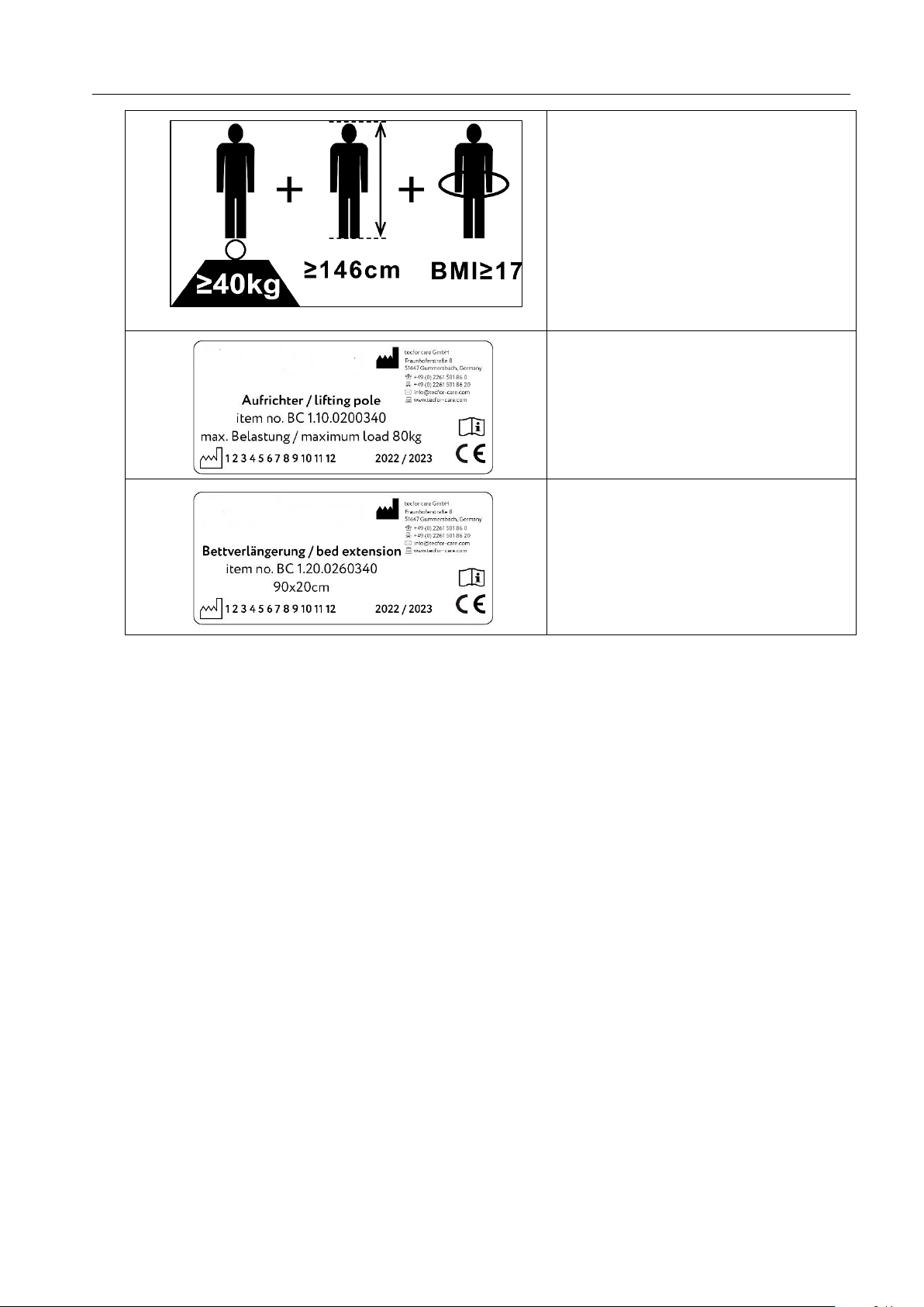
Instruction manual DESCEND
N
o
t
e:
Identification plate erector
Identification plate bed
_______________________________________
Use of the care bed for adults
Position:
l
d
e
b
he
t
f
o
e
d
i
s
r
e
p
up
e
m
a
r
F
frame at the foot side
)
on
i
t
op
(
Position:
Erector
)
n
io
t
p
o
(
n
o
i
s
en
ext
ng
i
ft
i
Position:
be
de
i
op s
T
d e
x
on
i
s
n
e
t
Last update:11.10.2022
Page 34 of 40
Page 35

Instruction manual DESCEND
_______________________________________
12.6 Information on electromagnetic compatibility
The Descend care bed meets the normative requirements with regard to its electromagnetic
interference emissions and its immunity to interference. Therefore, if the care bed is used as intended,
no functional restrictions are to be expected due to possible electromagnetic interference from
adjacent electrical devices.
Attention:
Nevertheless, the use of the care bed in the immediate vicinity of other electrical devices should be
avoided in order to prevent the care bed from malfunctioning due to electromagnetic interference. If it
is necessary to use the care bed in addition to other electrical devices, the proper functioning of the
care bed and these devices should be observed.
Only spare parts (mains cable, handset, motors, etc.) and accessories that have been approved by the
manufacturer Prius Healthcare may be used in order to be able to guarantee trouble-free operation of
the care bed.
The use of other accessories, other converters and other cables than those provided by Prius
Healthcare for this care bed can result in increased electromagnetic interference emissions or reduced
electromagnetic interference immunity of the care bed and lead to faulty operation.
Portable HF communication devices (mobile phones, two-way radios, etc.) including their accessories
(e.g. antenna cables and external antennas) should not be used within a distance of less than 30cm
from the electrical components and cables of the Descend care bed. Non-observance can lead to a
reduction in the performance characteristics of the care bed.
HF surgical devices must not be used on Descend care beds, as this can lead to unforeseeable
malfunctions in the care bed.
The Descend care bed is intended for use in the following specified electromagnetic environment
during its entire service life in order to maintain basic safety and functional characteristics.
The operator or user of the care bed should ensure that it is used in such an environment.
Last update:11.10.2022
Page 35 of 40
Page 36

Instruction manual DESCEND
Ambient limit values of the interference emissions
Phenomenon
operation site in the field of medical care in a home environment
C
o
n
d
uc
t
e
d
a
n
d
r
a
d
i
a
t
e
d
i
n
t
e
r
f
e
r
e
n
c
e
e
m
i
s
s
i
o
n
s
C
I
S
P
R
11,
G
r
o
up
1,
C
l
a
ss
B
Harmonic distortions
see IEC 61000-3-2
Voltage fluctuations and flicker
see IEC 61000-3-3
Phenomenon
E
M
C
b
a
s
i
c
s
ta
n
d
a
rd
o
r
te
s
t
me
t
h
o
d
Immunity test level
E
l
e
c
t
r
o
s
ta
ti
c
d
i
s
c
h
a
rg
e
I
E
C
6
1
0
0
0
±
8
k
V
co
n
t
a
ct
± 2 kV, ± 4 kV, ± 8 kV, ± 15 kV air
Hi
g
h
I
E
C
6
1
0
0
0
10 V/m ;( 80 MHz up to 2,7 GHz;
80% AM at 1 kHz)
Hi
g
h
i
m
m
e
d
i
a
te
vi
c
i
n
i
ty
o
f
w
ir
e
l
e
s
s
c
om
m
u
n
ic
a
t
i
on
d
e
v
ic
e
s
IEC 61000
see table Test specifications for the
i
m
m
u
n
i
t
y
o
f
s
h
e
a
t
h
i
n
g
s
t
o
h
i
g
h
f
r
e
q
u
e
n
c
y
w
i
r
e
l
e
s
s
co
m
m
u
n
i
ca
t
i
o
n
e
q
ui
p
m
e
n
t
(
a
t
t
h
e
e
n
d
o
f
t
h
i
s
c
h
a
p
t
e
r
)
M
a
g
n
e
t
i
c
f
i
e
l
d
s
w
i
t
h
e
n
e
r
g
e
t
ic
a
lly
r
a
t
e
d
f
r
e
q
u
e
n
ci
e
s
IEC 61000
30 A/m, 50 Hz or 60 Hz
Magnetic fields at close range
IEC 61000
n
o
m
a
g
n
e
t
ic
a
lly
s
e
n
s
it
iv
e
c
o
m
p
on
e
n
t
s
,
therefore no immunity rating required
Phenomenon
EMC basic standard or test
method
Immunity test level
S
h
o
r
t
,
t
r
a
n
s
i
e
n
t
e
l
e
c
t
r
i
c
a
l
d
i
s
t
u
r
b
a
n
c
e
s
/
b
u
r
s
t
s
I
E
C
6
1
0
0
0
±
2
kV
,
1
0
0
kH
z
re
p
e
t
i
ti
o
n
f
r
e
q
u
e
n
c
y
Surges: conductor to conductor
IEC 61000-4-5
± 0,5 kV, ± 1kV
C
o
n
d
u
c
t
e
d
i
n
t
e
r
f
e
r
e
n
ce
i
n
d
u
ce
d
b
y
frequency fields
IEC 61000
3 V
0,15 MHz up to 80 MHz
6
V
i
n
I
SM
a
n
d
a
m
a
t
e
u
r
r
a
d
i
o
f
r
e
q
u
e
n
c
y
bands between
0,15 MHz and 80MHz
80 % AM at 1kHz
vo
l
ta
g
e
d
i
p
s
I
E
C
6
1
0
0
0
0
%
U
;
½
p
e
r
i
o
d
a
t
0,
45,
90,
135,
180, 225, 270 and
315 degree
0
%
U
;
1
p
e
r
i
o
d
and
70% U
single
-phase at 0 degree
voltage interruptions
IEC 61000-4-11
0% UT; 250/300 periods
_______________________________________
The Descend care bed meets the requirements of the following EMC standards for interference
emission and interference immunity:
S
h
e
a
t
hi
ng
-
fr
e
q
u
e
n
c
y
e
l
e
c
t
r
o
m
a
g
n
e
t
i
c
fi
e
l
d
s
-
fr
e
q
u
e
n
c
y
e
l
e
c
t
r
o
m
a
g
n
e
t
i
c
f
i
e
l
d
s
i
n
t
h
e
-
4
-
2
-
4
-
3
-4-3
-
-4-8
A
C
por
t
f
o
r
s
u
p
pl
y
i
n
p
u
t
-4-39
-
4
-
4
h
i
g
h
-
-4-6
Last update:11.10.2022
Page 36 of 40
T
-
4
-
1
1
T
; 25/30 periods
T
Page 37
Instruction manual DESCEND
Ph
en
o
men
o
n
E
M
C
b
a
s
i
c
s
ta
n
d
a
rd
o
r
te
s
t
me
t
h
o
d
I
m
m
u
n
i
t
y
te
s
t
l
e
ve
l
S
h
o
r
t
,
t
r
a
n
s
i
e
n
t
e
l
e
c
t
r
i
c
a
l
d
i
s
t
u
r
b
a
n
c
e
s
/
b
u
r
s
t
s
I
E
C
6
1
0
0
0
± 2 kV
100 kHz repetition frequency
Surges: conductor to conductor
IEC 61000-4-5
± 0,5 kV, ± 1kV
S
u
r
g
e
s
:
c
o
n
d
u
c
t
o
r
t
o
e
a
r
t
h
IEC 6
1
0
0
0
-4-5
±
0
,
5
k
V
,
±
1
k
V
,
±
2
k
V
Conducted interference induced by high
fr
e
q
u
e
n
c
y
fi
e
l
d
s
I
E
C
6
1
0
0
0
3 V
0,15 MHz up to 80 MHz
6 V in ISM and amateur radio frequency
b
a
n
d
s
b
e
t
w
e
e
n
0,
15
M
H
z
a
nd
80M
H
z
80 % AM at 1kHz
P
a
t
i
e
n
t
s
’
c
on
n
e
ct
i
on
por
t
s
Phenomenon
EMC basic standard or test
me
t
h
o
d
Immunity test level
El
e
ct
r
o
s
t
a
t
i
c
d
i
s
ch
a
r
g
e
I
E
C
6
1000
±
8
k
V
co
n
t
a
ct
±
2
k
V
,
±
4
k
V
,
±
8
k
V
,
±
1
5
k
V
a
i
r
C
o
n
d
u
c
t
e
d
i
n
t
e
r
f
e
r
e
n
c
e
i
nd
u
c
e
d
b
y
hi
g
h
frequency fields
I
E
C
6
1000
3 V
0,
15
M
H
z
up
t
o
80
M
H
z
6
bands between
0,15 MHz and 80MHz
80 % AM at 1kHz
SIP/SOP-Tor (Signaleingangs-
P
h
e
n
o
m
e
no
n
E
M
C
b
a
s
i
c
s
ta
n
d
a
rd
o
r
te
s
t
method
I
m
m
u
n
i
t
y
te
s
t
l
e
ve
l
Electrostatic discharge
IEC 61000
± 8 kV contact
± 2 kV, ± 4 kV, ± 8 kV, ± 15 kV air
S
h
o
r
t
,
t
r
a
n
s
i
e
n
t
e
l
e
ct
r
i
ca
l
d
i
s
t
u
r
b
a
n
ce
s
/
b
u
r
s
t
s
I
E
C
6
1000
±
1
k
V
1
0
0
k
H
z
r
e
p
e
t
i
t
i
o
n
f
r
e
q
u
e
n
c
y
Conducted interference induced by high
frequency fields
IEC 61000
3 V
0,
15
M
H
z
up
t
o
80
M
H
z
6 V in ISM
bands between
0,
15
M
H
z
a
nd
80M
H
z
80 % AM at 1kHz
_______________________________________
DC port for supply input
-
4
-
4
-
-
4
-
6
-
4
-
2
6
-
4
-
V
i
n
I
SM
a
n
d
a
m
a
t
e
u
r
r
a
d
i
o
f
r
e
q
u
e
n
c
y
/Signalausgangsteilen)
-4-2
-
4
-
4
-
-4-6
and amateur radio frequency
Last update:11.10.2022
Page 37 of 40
Page 38
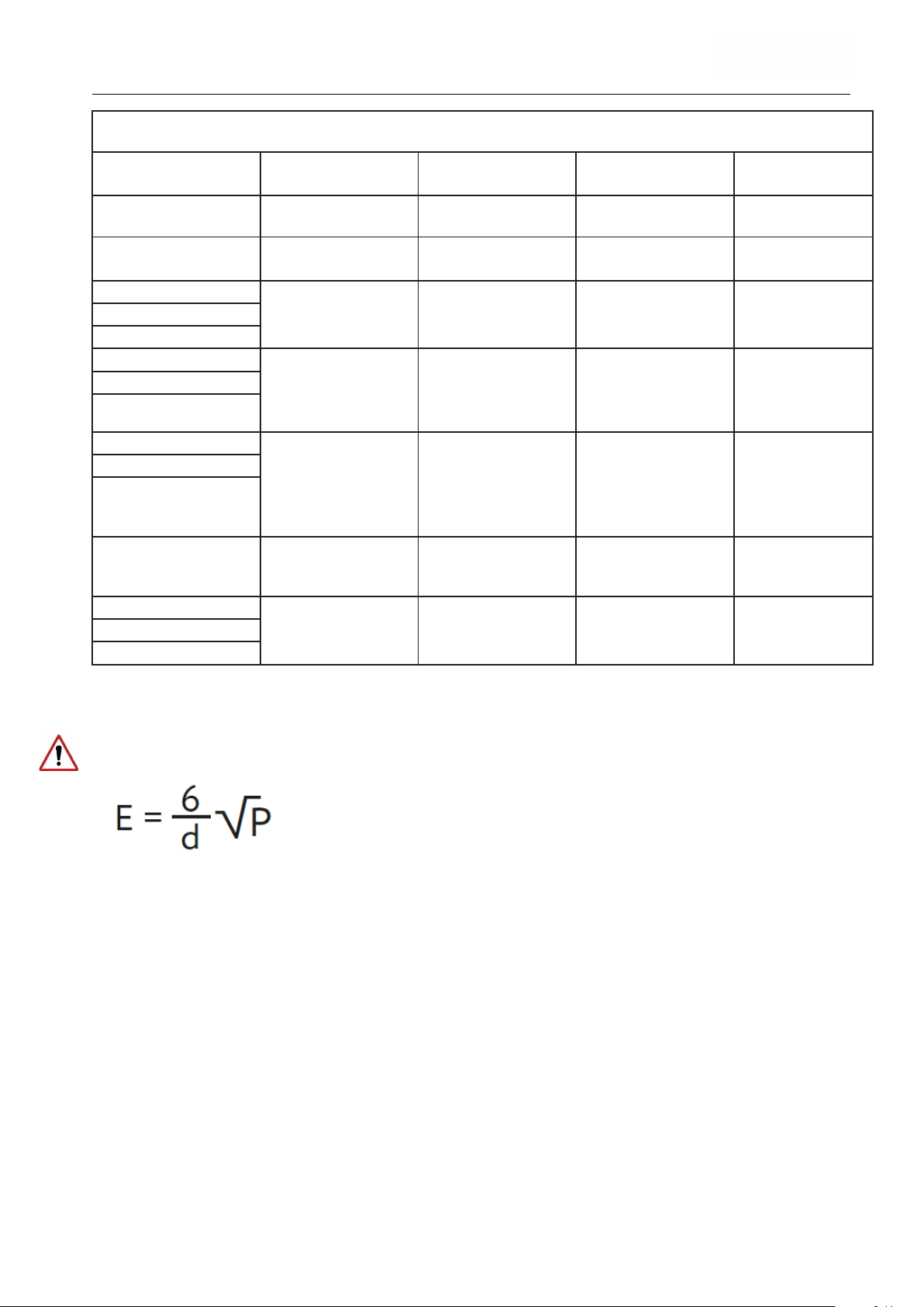
Instruction manual DESCEND
T
e
s
t
s
p
e
c
i
f
i
c
a
t
i
on
s
f
or
t
h
e
i
m
m
u
n
i
t
y
o
f
s
h
e
a
t
h
i
n
g
s
t
o
h
i
gh
-f
r
e
q
u
e
n
cy
w
i
r
e
l
e
s
s
c
om
m
u
n
i
c
a
t
i
on
e
q
u
i
p
m
e
n
t
T
e
s
t
F
r
e
q
u
e
n
c
y
(MHz)
F
r
e
q
u
e
n
c
y
b
a
n
d
(MHz)
I
m
m
u
n
i
t
y
te
s
t
l
e
ve
l
(v/m)
Pulse modulation 18
Hz
FM
± 5% lift, 1kHz sine
710
745
780
810
G
S
M
8
0
0
/
9
0
0
,
T
E
T
RA
LT
E
B
a
n
d
5
870
930
1720
G
S
M
18
0
0,
C
D
M
A
U
M
T
S
1845
1970
Bluetooth, WLAN
2
4
5
0
,
LT
E
b
a
n
d
7
Pulse modulation 217
28
5240
5500
5785
P = maximum power in watts (W)
_______________________________________
Radioservice Modulation
385 380 to 390 TETRA 400
450 430 to 470 GMRS 460, FRS 460
70
4
t
o
7
87
80
0
t
o
9
60
17
00
t
o
19
90
2450 2400 to 2570
5100 to 5800 WLAN 802.11 a/n
LT
E
b
a
n
d
1
3
,
1
80
0
i
D
E
N
8
2
0
,
C
D
M
A
8
1900,
GSM 1900, DECT,
L
T
E
b
a
n
d
1
;
3
;
4
;
802.11 b/g/n, RFID
7
5
25
Pulse modulation 217
P
u
0,
Pulse modulation 217
;
Pulse modulation 217
Hz
l
s
e
m
o
d
Hz
Hz
Hz
Hz
27
28
9
u
l
a
t
i
o
n
1
8
28
28
9
The minimum distances for higher immunity test levels shall be calculated using the following
equation.
d = Minimum distance in meters (m)
E = Immunity test level in volts per meter (V/m)
If a test with these increased test levels is passed, the stated minimum distance of 30cm can be
replaced by the new minimum distance calculated for the increased immunity test levels.
Last update:11.10.2022
Page 38 of 40
 Loading...