

Page 1

User’s Manual
General Purpose Input/Output (GPIO)
Manager and Module
Page 2

Page 3

Product Warranty
Printronix warrants that the Products furnished under this Agreement shall be
free from defects in material and workmanship for a period of one year from
the date of shipment from the Printronix facility. This warranty is applicable
only if the products have had normal utilization within the published
specifications as modified from time to time, have been maintained in
accordance with recommended procedures with Printronix approved parts,
and have not been modified or altered in a manner not approved by
Printronix.
For printers sold within the area in which Purchaser normally provides field
service:
For all printers the Purchaser will provide the end-user with a 90-day
on-site warranty. Any printer or part therein found defective within one
year of original shipping date from a Printronix facility shall be returned to
Printronix and be repaired or replaced at the option and expense of
Printronix. Purchaser shall pay shipping cost to the Printronix facility and
Printronix will return the item(s) at its expense.
For printers sold outside the area, within the Continental United States, in
which Purchaser normally provides field service:
Any printer found defective within 90 days from the date of shipment to
the end user will be repaired at the end user’s location. If the end user is
located within 100 miles of an Authorized Service Provider’s location,
warranty service will be performed at no charge. If the end user is located
more than 100 miles from an Authorized Service Provider’s location,
travel time and expenses in excess of 100 miles will be billed to the end
user at current rates or the printer may be shipped to the nearest
Authorized Service Center for repair. If the end user elects to ship the
printer for warranty repair, the end user shall pay the shipping cost to the
Authorized Service Center and the printer will be returned at Printronix’
expense.
The Products may be equipped with a general purpose input/output circuit
board and corresponding pin connection (GPIO) which allow the Purchaser’s
or end user’s printer to function as a controller in a computer system.
Printronix publishes the specifications associated with GPIO and the pin
connection and warrants that the printer’s input and output parameters at the
pin connection conform to those specifications. Except as expressly
warranted, GPIO is sold on an “as is” basis. There are no other warranties
whatsoever, express or implied, concerning GPIO.
Purchaser’s remedies are expressly limited to Printronix’ obligations as stated
above, and in no event shall Printronix be held liable for any incidental or
consequential damages or loss of use, or other commercial loss, however
occasioned.
The warranties set forth in this article and the obligations and liabilities
thereunder are in lieu or, and the purchaser hereby waives, all implied
guarantees and warrantees, including without limitation, any warranty of
merchantibility or fitness for a particular purpose. In no event shall Printronix
be held liable for any incidental or consequential damages or loss of use, or
other commercial loss, however occasioned.
Page 4

Notice of Copyright
This document contains proprietary information protected by copyright. No
part of this document may be reproduced, copied, translated, or incorporated
in any other material in any form or by any means, whether manual, graphic,
electronic, mechanical, or otherwise, without the written consent of Printronix,
Inc.
All non-Printronix registered and/or unregistered trademarks used throughout
this manual are the sole property of their respective owners.
COPYRIGHT 2003, 2005, PRINTRONIX, INC.
All rights reserved.
Page 5

1 Introduction ........................................................... 7
Overview................................................................................................ 7
Events and Actions ................................................................................ 7
The Hardware ........................................................................................ 7
2 The GPIO Manager............................................... 9
Overview................................................................................................ 9
The Menus .................................................................................... 10
The Entry Fields ............................................................................ 11
Password ...................................................................................... 12
Events and Actions ....................................................................... 13
Entry Control Buttons........................................................................... 23
Multiple Actions ............................................................................. 24
The ON Flag.................................................................................. 25
The Initial State ............................................................................. 25
Data Fields........................................................................................... 26
Data Field Events And Actions...................................................... 27
Data Field Events .......................................................................... 29
Defining Reports .................................................................................. 31
Sections ........................................................................................ 33
Reports.......................................................................................... 35
Using Reports ............................................................................... 36
3 Mapping .............................................................. 37
Download Mapping Tables .................................................................. 37
Pre-Loaded Table ................................................................................ 37
Mapping Examples .............................................................................. 38
PPI-1 ............................................................................................. 39
PPI-2 ............................................................................................. 41
Printronix T3000 and Equivalent Printers...................................... 44
Other Competitors ......................................................................... 46
Indicator Lights Example ............................................................... 48
Simple Applicator Example ........................................................... 50
Protected Printer Example ............................................................ 51
Panel Selected Label Printing ....................................................... 52
Table of Contents
Page 6

Table of Contents
A Technical Information .......................................... 55
Opto-couplers ...................................................................................... 55
Relays.................................................................................................. 56
Voltages............................................................................................... 56
I/O Connector ...................................................................................... 56
B Basic GPIO Schematic Diagram ......................... 59
C Electrical Inputs And Outputs.............................. 61
GPIO Opto-coupled Input Circuit ......................................................... 61
GPIO Opto-coupled Output Circuit ...................................................... 61
Page 7

7
1 Introduction
Overview
This document describes the Printronix General Purpose Input/Output (GPIO)
function available for the Printronix T5000 series Thermal printers and the
P5000 series Line Matrix printers.
GPIO is both hardware and software. The hardware is
the I/O board to be
mounted in the printer
, and the software is the GPIO Manager which is part of
the Printronix Remote Management Software Advanced Tool Kit. The GPIO
hardware is a printed circuit board containing optically isolated inputs and
outputs as well as relays. The GPIO software is both a printer resident GPIO
event parser and a PC-based GPIO manager that allows the user to define
how the general purpose I/O hardware should behave for the given
application.
Events and Actions
The operation of GPIO is based on Events and Actions. Events can be either
printer internal such as “paper out” or “print complete,” or they can be printer
external such as “opto-coupler 1 active.” Actions are the result of (or the
reaction to) an event and can be printer internal such as “paper feed” or
printer external such as “relay 1 active” or “reply to host” where data is
transmitted over the serial, parallel, or network interface. You can also define
a number of events to be acted upon without the GPIO card installed in the
printer, which allows the printer to be adapted for the application in use.
The Hardware
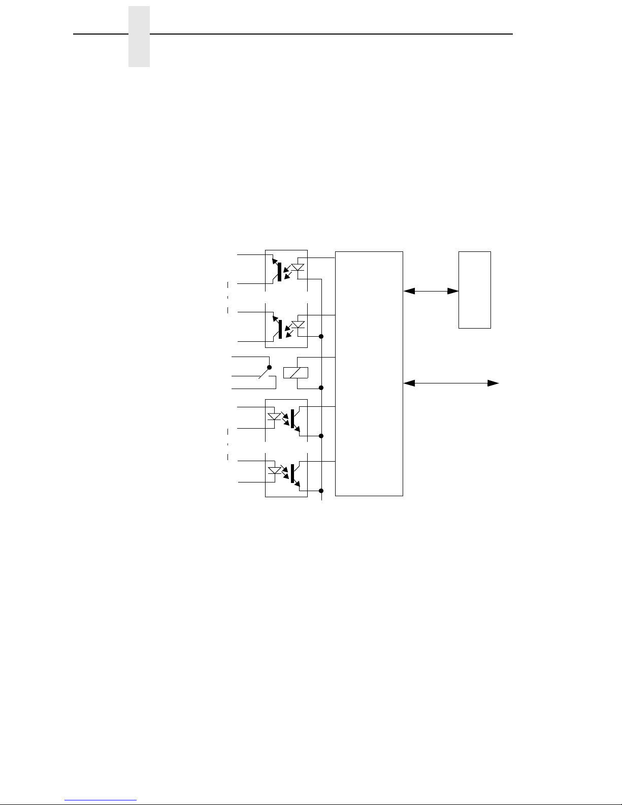
The GPIO hardware (see Figure 1 on page 8) consists of 16 opto-couplers,
4 SPDT relays, a real time clock, and the logic required to connect this
hardware into the printing system.
NOTE: Although the GPIO hardware includes a real time clock, it will not be
described in this manual. Its programming and use are strongly
related to PGL and equivalent languages, and those manuals
document the real time clock.
Page 8
8
Chapter 1 The Hardware
Eight of the 16 opto-couplers are used as isolated inputs; these are the
connections on which the external events happen. The remaining eight
opto-couplers and the four SPDT relays are used as isolated outputs. Each of
these outputs can be activated as an action in response to some event. The
board is connected into the printing system through the printer’s expansion
port.
None of the inputs or outputs is connected to any voltage source; it is the
user’s responsibility to make those connections. A separately fused
5-volt and a separately fused 24-volt are available on the 50 pin connector in
which all inputs and outputs are terminated.
Figure 1. GPIO Hardware
GPIO
Logic
Outputs 1 . . 8
R
T
C
System Interface
Relay 1 . . 4
Inputs 1 . . 8
Page 9

9
2 The GPIO Manager
Overview
The GPIO Manager is part of the Advanced Tool Kit (ATK) version of the
Printronix Remote Management Software (RMS).
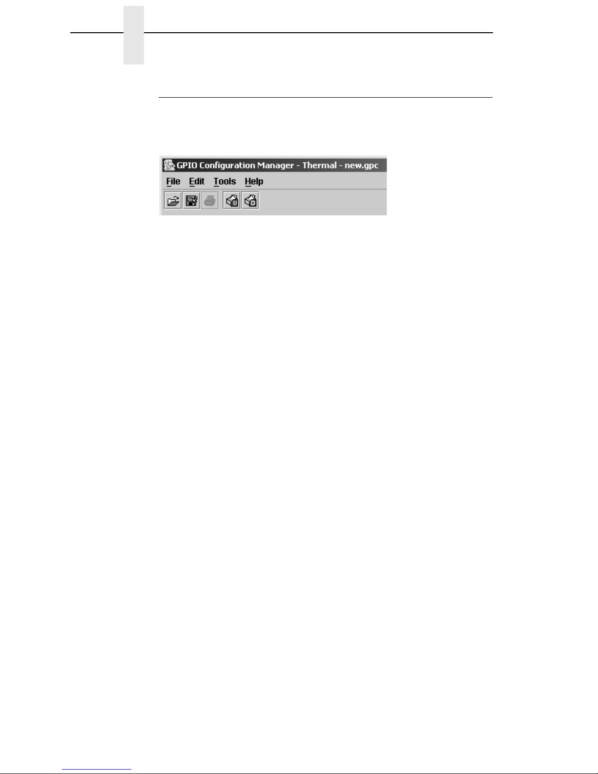
To access the GPIO Manager, click the icon in the RMS/ATK toolbar or
select Applications
GPIO Manager. The screen in Figure 2 displays. The
fields on this screen is described in detail in the following pages.
Figure 2. The GPIO Configuration Manager
Page 10
10
Chapter 2 Overview
The Menus
The toolbars are like any other toolbar; they allow the usual handling of files
and text.
Figure 3. The GPIO Configuration Manager Toolbar
File
The File menu allows you to create, open, or save a new or existing I/O
configuration. The Print option is currently disabled. The Properties option
allows you to select the type of printer, Thermal or Impact, that the I/O
configuration is to be created for. Password allows you to attach a password
to a mapping table.
Edit
The Edit menu allows you to define, delete, and rename mapping tables. You
can also define data fields and reports to customize mapping table.
Tools
The Tools menu allows you to upload or download an I/O configuration. You
also have the option to select the last selected upload printer or the last
selected download printer. This option allows you to quickly select a
previously uploaded or downloaded printer without having to go to the RMS
printer database for your selection.
Help
The Help menu allows you to open the User Guide of this program if the guide
is stored in the correct directory on the user’s system. If it cannot be found, an
error message displays. The About option provides basic information about
the GPIO Configuration Manager as seen in the startup splash screen.
Page 11
The Entry Fields
11
The Entry Fields
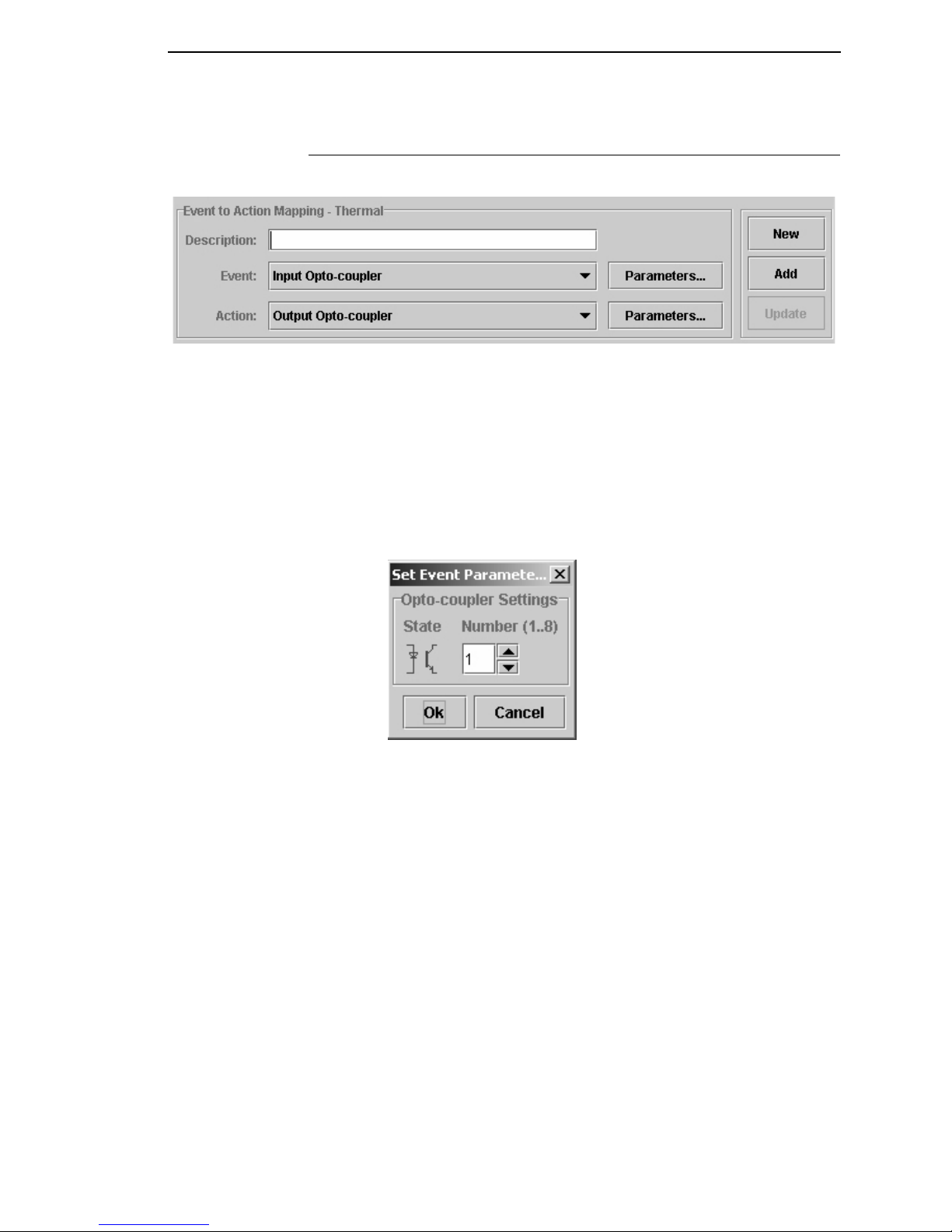
Figure 4. The Event To Action Mapping Fields
Setting the criteria for mapping tables takes place here (Figure 4). The
Description
field allows you can enter a descriptive name to indicate the use
of the event and its related action.
NOTE: The window header indicates which printer the mapping table is
created.
The Event field allows you to select the event on which some action is to be
taken. Table 1 on page 13 lists the events currently available in the software.
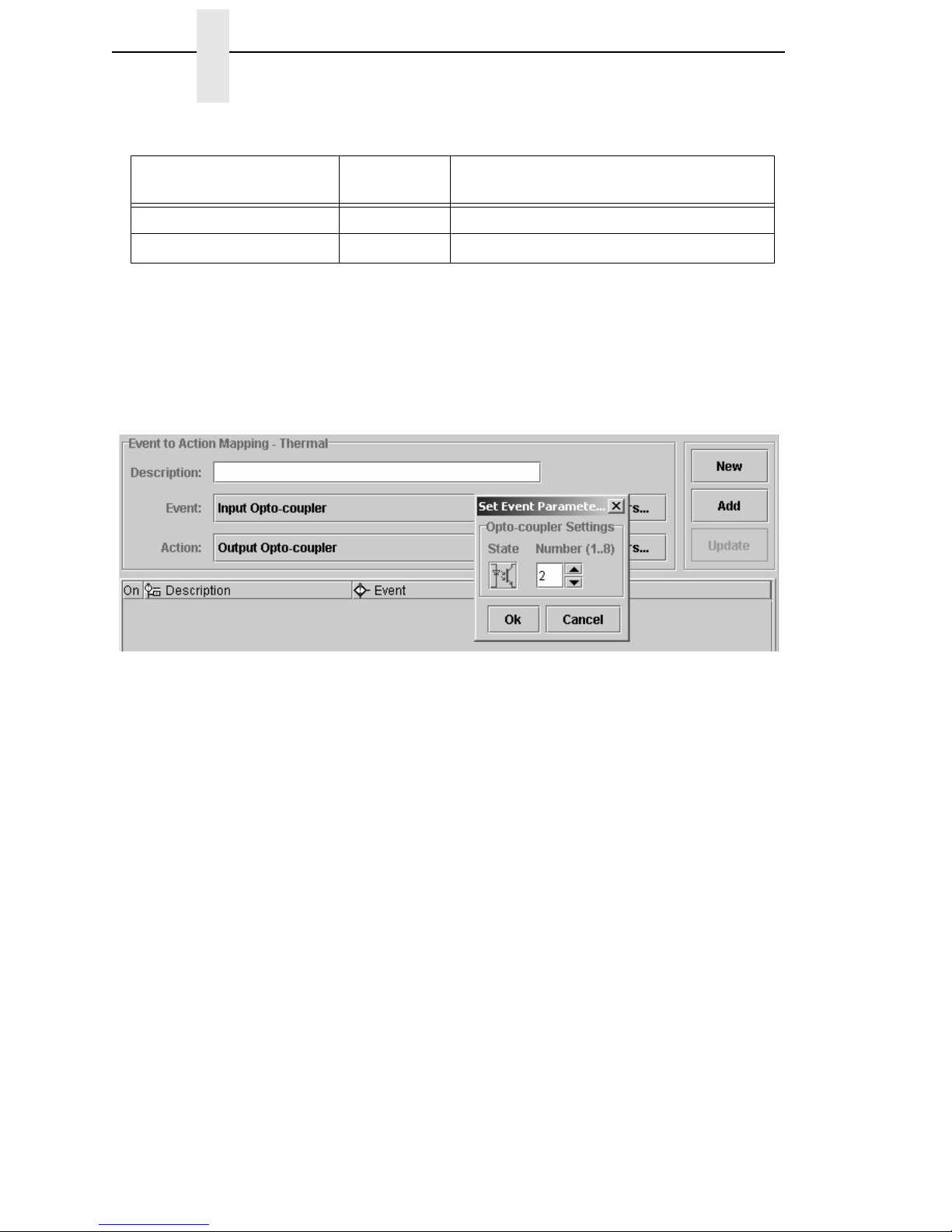
Figure 5. Setting Event Parameters
The Event Parameters button allows you to select additional conditions
related to the event (Figure 5).
Page 12
12
Chapter 2 Overview
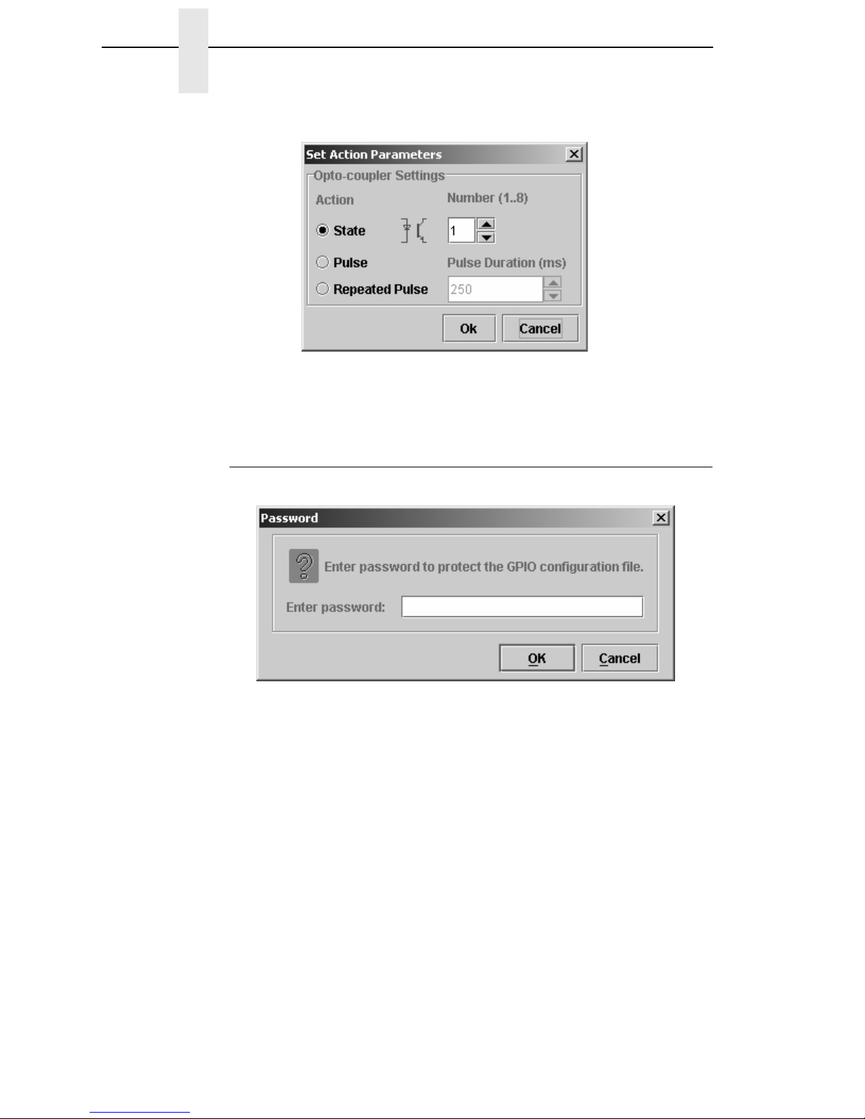
Figure 6. Setting Action Parameters
The Action Parameters button allows you to select all possible actions that
are programmed to take place as a result of some event (Figure 6).
Password
Figure 7. Setting Passwords
A password can be attached to the mapping table (also called the GPIO
Configuration file). This password will be stored, in the GPIO configuration
file, in the printer’s flash memory. Uploading of a password-protected file is
possible, but before any operation can be performed on or with this file, you
must enter the password.
Page 13

Events and Actions
13
Events and Actions
The Events
Table 1 lists the available events and the related parameters. Each of the
events will be described separately. Parameters on events are valid for the
Input Opto-Couplers, Panel Key Pressed events, ODV events, Printer Error
and Warning events, and PAA events.
Table 1: Events And Parameters
Events Printer Type Parameters
Input Opto-Coupler Opto-Coupler Number (1..8), Active, Inactive
Printer Powered Up n.a
Printer Online n.a
Printer Offline n.a
Printer Local n.a
Power Save Mode Active n.a
Power Save Mode Cleared n.a
Start Data Processing n.a
End Data Processing n.a
Printer Buffers Empty n.a
Label Pending Thermal n.a
Start Printing n.a
Start Paper Move
Impact n.a
Label Printed Thermal n.a
Label Present Thermal n.a
Label Taken Thermal n.a
Job Printed n.a
End Paper Move
Impact n.a
Printer Error Thermal Any, Paper Out, Paper Jam, Ribbon Out,
TOF Detect Fault, Head Open, RFID Tag
Failed, RFID Max Retry
Impact Any, Platen Open Paper Jam, Paper Empty,
Ribbon Stall, Stacker Fault, Stacker Full
Printer Warning Thermal Any, Ribbon Low
Panel Key Event Thermal Printer Type related Key Description
Page 14
14
Chapter 2 Overview
Event Descriptions
• Input Opto-Couplers
For external input signals. You can specify the number of the
opto-coupler to view and the level on which the event is seen as active.
Clicking the opto-coupler symbol selects the active state.
Figure 8. Setting the Opto-coupler Number and State
• Printer Powered Up
This event is delayed until the moment the printer reaches the Poweredup-online or Powered-up-offline state. The delay is required so the printer
can finish its power-on reset cycle before any reaction to an event is
generated.
• Printer Online
When the printer goes online by pressing the Pause key, the action
related to this event is taken.
• Printer Offline
When the printer goes offline by pressing the Pause key or the menu key,
or if there is any other reason that causes the printer to switch offline, the
action related to this event is taken.
• Printer Local
This event happens when the printer is paused by pressing the Pause
key. The printer accepts data from the host and parses this data until its
buffers are full. No printing occurs. The print engine is offline, but the
printer’s data processing unit is still online.
ODV Events Thermal Missing barcode, Quality error – Any or a
specific one, All ODV errors cleared
PAA Event Event identifier
Data Field Changed Data Field, Condition, Type, Value
Table 1: Events And Parameters
Page 15

Events and Actions
15
• Power Save Mode Active
This event signals the moment when the printer enters Power Save
Mode.
• Power Save Mode Cleared
Opposite of the Power Save Mode Active, this mode signals the moment
the printer becomes active.
• Start Data Processing
This event signals the start of the processing of received data. This is not
the same as the Start Printing event.
• End Data Processing
This event signals the end of the data processing cycle. This is not the
same as the end printing event.
• Buffers Empty
This event takes place as soon as the print buffers are emptied.
• Label Pending
This event generates when the printer is in Local mode (i.e., the print
engine is temporarily stopped) and all incoming data has been processed.
• Start Printing
This event happens when the printer starts printing. The printer starts
printing when all data processing is done, there is actual data to print, and
the printer is no longer in local mode. The event will not happen on “paper
moves without print.”
• Start Paper Move
This event is only available in the Impact Printer mode of the GPIO
Manager. It indicates the beginning of the paper motion.
• Label Printed
This event occurs when a number of labels stored in the printer have
finished printing. If the labels print as a single job without any wait time,
the event will be a short pulse. If the printer is placed in local mode and
the labels are printed using the
print next label
action, the event will
happen once for each label.
• Label Present
In label peel off applications, this event happens when the label present
sensor detects a label in position (ready for application). It may be used to
signal the availability of a label to an applicator system.
• Label Taken
This event is generated when the label is taken from its ready to apply
position. It can be used to tell the host that a new label can be printed.
• Job Printed
This even is generated if everything in the buffer has been printed.
Page 16
16
Chapter 2 Overview
• End Paper Move
This event is only available in the Impact Printer mode of the GPIO
Manager. It indicates the end of the paper motion.
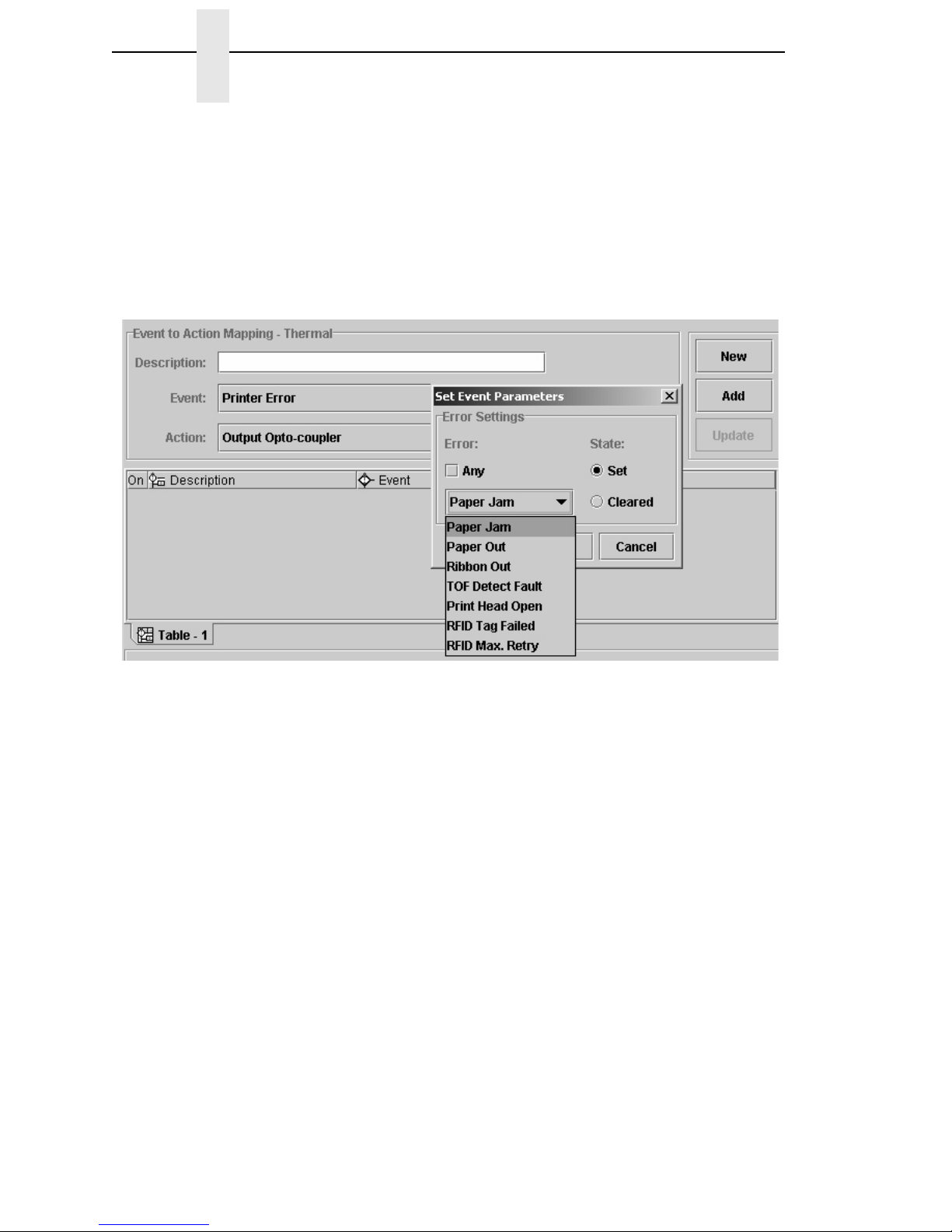
• Printer Error/Printer Warning
These events signal printer errors and warnings. They allow selection of
the error or warning that is seen as the event. Impact printers do not
support warnings.
Figure 9. Setting Errors for an Event Parameter
To select the Printer Error event, click the Event drop-down menu and
select Printer Error as the event parameter. Click the Parameters button
to the right of the event then click the Any box to uncheck the setting. A
list of errors (or warnings) is now available for selection. From the Error
drop-down menu, select the required parameter (Figure 9).
The Set state identifies the event when the problem happens. The
Cleared state specifies the event when the problem is solved.
Page 17

Events and Actions
17
• Panel Key Event
This is an event in which the operator panel keys are parameters. The
event allows you to change the function of some of the keys or to disable
selective keys. For example, if the panel key event with JOB SELECT/
DECREMENT(-) results in the action “Do Nothing,” the menu key is
disabled.
Figure 10. Setting Panel Key Event Parameters
• ODV Events
This selection allows you to react to output from the Online Data
Validator. The parameters allow you to program GPIO to act when there
is no barcode, when there are barcode errors, or when all ODV errors are
cleared. This event is not available for Impact printers.
Figure 11. ODV Event Parameters
Page 18
18
Chapter 2 Overview
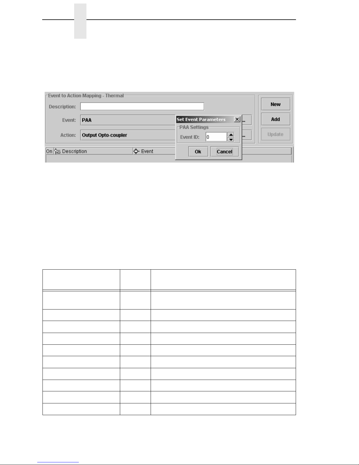
• PAA Event
PAA generates an event on a user-specified input string. A large number
(32000+) of PAA events can be generated through the use of an
identifier.
Figure 12. PAA Event Parameters
• Data Field Changed
This event happens if the value in a given data field changes. Certain
conditions are applicable. See “Data Fields” on page 26.
The Actions
The Action field allows you to specify which action should be linked (or
mapped) to the selected event. Table 2 lists all possible actions and related
parameters.
Table 2. Event Actions and Parameters
Actions
Printer
Type
Parameters
Output Opto-Coupler Opto-Coupler Number (1..8), Activate, Deactivate,
Pulse
Output Relay Relay Number (1..4), Activate, Deactivate, Pulse
Printer Online n.a
Printer Offline n.a
On/Offline Switch n.a
Clear Buffer n.a
Pulse Printing n.a
Start Printing n.a
Print Next Label Thermal n.a
Reprint Last Printed Label Thermal n.a
Page 19

Events and Actions
19
Form Feed n.a
Move Paper TOF, Specified Distance Forward/Backward
Cut Once Thermal n.a
Delete Page n.a
Lock Operator Panel n.a
Unlock Operator Panel n.a
Keyhandling Consume
Disable GPIO Events n.a
Enable GPIO Events n.a
Reply to Host Data to be Transmitted, Interface to be used
Wait Time to Wait in mSeconds
PAA Control: Reset CST
Select Mapping Table Name of Table to switch to
Data Field Destination, Operator, Source, Type
Send Report Name, Destination, Duration
Table 2. Event Actions and Parameters
Actions
Printer
Type
Parameters
Page 20
20
Chapter 2 Overview
Action Descriptions
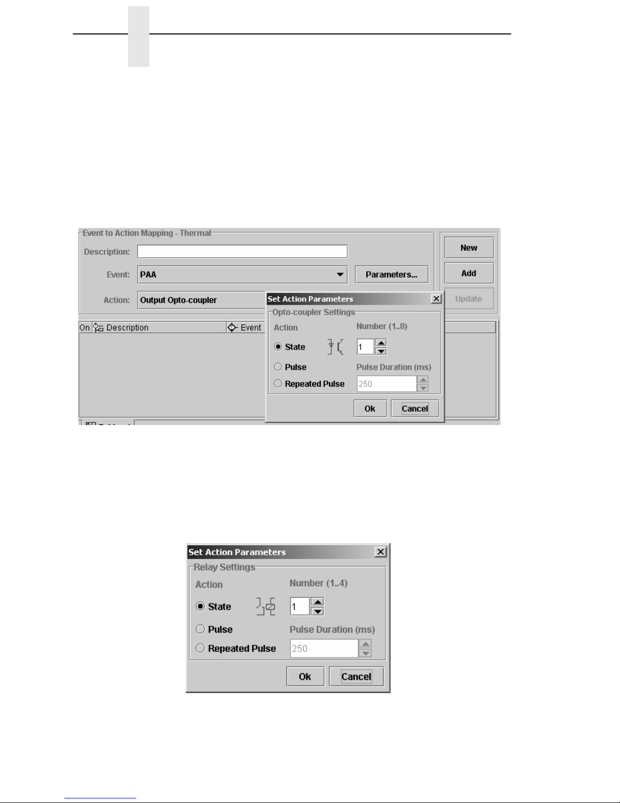
• Output Opto-Couplers
The opto-coupler number to activate can be specified as well as the level
(or state) required for this output. You can select the state by clicking the
opto-coupler symbol. If the Pulse parameter is selected, the pulse
duration can be set in increments of 50 msec between 50 and
2,147,483,647 msec. This allows pulses up to 24.8 days in duration. If
Repeated Pulse is selected, the pulse will repeat with a 50% duty cycle
until deactivated.
Figure 13. Setting Ouput Opto-coupler Action Parameters
• Output Relay
The relay number to activate can be specified as well as the level (or
state) required for this output. You can select the state by clicking the
relay symbol. Pulsed behavior for the relays is equivalent to the pulsed
behavior of the opto-coupled outputs.
Figure 14. Output Relay Settings
Page 21

Events and Actions
21
• Printer Offline / Printer Online
These two actions switch the printer offline or online.
• On/Offline Switch
This action allows the printer to be switched offline if it is online, and to be
switched online if it is offline. The switch works as a toggle.
• Clear Buffer
A host or application controlled memory clear.
• Pause Printing
This action results in the print engine going offline with the interface to the
host still active. This allows receiving and pre-processing of host data
until the buffer is full.
• Start Printing
If there is data in the buffer, the printer will start printing until either
switched offline or paused through the Pause Printing action.
• Print Next Label
This is an action which is a combination of the Start Printing and Pause
Printing actions. The printer is taken off Pause mode, a Start Printing
command is generated, and the printer is immediately placed in Pause
mode again. With the T5000e being a page printer, this results in the label
being finished and the printer ending in Pause mode.
• Reprint Last Printed Label
Reprints the last page printed.
• Form Feed
Performs a form feed.
• Move Paper
This action allows the movement of paper either to the next top-of-form
(the gap) or, if required for specific applicator functions, a specified
distance forward or backward.
Figure 15. Setting Move Paper Action Parameters
Page 22

22
Chapter 2 Overview
• Cut Once
Cuts the media in the current position.
• Delete Page
Deletes the page currently in memory and ready to print.
• Lock Operator Panel / Unlock Operator Panel
Once executed, the front panel will be locked or unlocked. When locked,
the panel can still be accessed through the virtual front panel of the
Printronix Remote Management Software Advanced Tool Kit. If the
Disable Event Parser has been executed, the front panel will be unlocked.
• None
An action that stops actions. If connected to a key pressed event, that key
is effectively disabled.
• Enable GPIO Events / Disable GPIO Events
These actions allow you to switch on or off the event parsing of GPIO.
When disabled, the only action GPIO will execute is the enable event
parser action.
• Reply to Host
The Reply to Host action allows the user to specify a data stream that will
transmit to the host when the selected event takes place and to select the
interface that should be used for this data transmission. Data entry can be
in ASCII or in hexadecimal. The entry mode can be selected with the
arrow keys: up-arrow for ASCII entry mode and down-arrow for Hex entry
mode.
Figure 16. Setting Reply to Host Action Parameters
• Wait
The parameter for this action specifies the time (in 1/1000 seconds) that
GPIO will wait until the next action executes.
• PAA Control: CST Reset
This action resets the Use Once flags of the currently active PAA CST.
Page 23

Events and Actions
23
• Select Mapping Table
This action allows you to select one out of 64 mapping tables on a given
event. If only a single mapping table has been defined, this selection is
not available. The mapping table is selected by its name.
• Data Field
This action allows you to modify the data field on a given event. Several
logical or arithmetical functions can be applied to the data in the data
field. See “Data Fields” on page 26.
• Send Report
This action transmits a report to either the host computer through a
selected interface or to the printer front panel LCD. For the LCD the user
can select the upper or lower display line and the time the message will
be visible. See “Defining Reports” on page 31.
Entry Control Buttons
The mapping table control buttons are used as follows:
• New: Clears the Name field and sets the Event, Action, and related
parameters to default.
• Add: Adds a new Event-to-Action mapping to the current I/O
Configuration.
• Update: Re-enters an Event-to-Action mapping after editing.
Click the buttons to copy an entry from the mapping table to the entry/edit
fields for subsequent modification. Click the Update button to update the entry
in the mapping table with the new data.
Figure 17. Event to Action Mapping Entry Control Buttons
Page 24

24
Chapter 2 Entry Control Buttons
Multiple Actions
If required, GPIO can execute a number of actions on a single event. Multiple
actions specified for a single event will be executed in the order they are
entered in the mapping table.
Figure 18 shows a mapping table where the first action is to enable GPIO
events by making the Input Opto-coupler event active. The second action is to
disable GPIO events by making the Input Opto-coupler event inactive. The
third action is to perform a form feed. Since the GPIO Configuration Manager
performs mappings in sequence, this program will not produce a clean sheet
because the Form Feed action follows the GPIO disable command. A form
feed cannot happen when all GPIO events are disabled first.
Figure 18. Incorrect Setup of Multiple Actions
Figure 19 shows a correct mapping table; a form feed is executed before the
actual disabling of GPIO.
Figure 19. Correct Setup of Multiple Actions
Page 25

The ON Flag
25
The ON Flag
You can use the On flag to temporarily disable entries in the GPIO mapping
table. This is useful if an extensive mapping table is generated with many
events leading to the same action. The On flag allows you to test each event
reaction separately without confusion.
Figure 20. Using the On Flag to Enable or Disable the Same Action
The Initial State
Since the initial state of the input opto-coupler is unknown (it can be either on
or off depending on the equipment to be controlled), it is important to specify
what GPIO can expect on its input interface. This is done by moving the
cursor over the virtual LEDS and clicking those that will be active at the
power-on time of the connected equipment. Once this is done, any deviation
from this setting will be seen as an event, and if programmed, will be acted
upon.
Figure 21. Initial GPIO Input State
The tabs marked Map 1 and Map 2 allow selection of different Event-to-Action
mappings. Currently, only a single mapping (Map 1) is supported.
To change the entries sequence in the table, you can click and drag an entry
to a different location in the table.
Page 26

26
Chapter 2 Data Fields
Data Fields
Figure 22. The Define Data Fields Dialog Box
Data fields are storage locations in the printer’s resident memory. To define a
data field, select Edit
Define Data Fields. The Define Data Fields dialog
box opens (Figure 22).
The Name field allows the user to create a data field descriptive to the user’s
needs. The Type drop down menu allows you to choose one of seven
different types of data including 8, 16, or 32 bit signed or unsigned values and
a string value. The Initial Value field allows you to set an initial value for the
data type specified.
Checking the Non Volatile check box specifies that if a value in the data field
has changed during the operation of the printer and the printer is powered
down, the lastest value of the data field will be the initial value when the
printer is powered on. For example, if the data field contains a label count of
10,000 and that after printing 1,200 forms the printer is turned off due to error,
with Non Volatile selected, the printer prints another 8,800 forms when the
printer goes online again. If Non Volatile is not selected, the printer will print
another 10,000 forms.
Page 27

Data Field Events And Actions
27
Data Field Events And Actions
Data Field Actions are used to modify the content of the Data Field which
results in an event.
An example is provided to better understand how Data Field Actions work in
correlation to Data Field Events. For this example, we have a printer with a
forms count defined in a data field in which after each form prints, the count is
updated to reflect the correct number of forms still to be printed. Once the
count reaches zero, we want a message to display in the second line of the
front panel. To do this, we need to define a Data Field and enter the total
forms count (Figure 23).
Data Field Actions
Figure 23. Defining Data Fields
1. Select Edit
Define Data Fields.
2. Enter a descriptive name in the Name field.
3. Select the Data Field Type and enter the Initial Value.
Page 28

28
Chapter 2 Data Fields
To decrement the label count by one each time a form prints, specify this
event to happen in the Data Field parameter block when a label printing
occurs. Operator Data Field Settings are defined in Table 3.
First specify the data field itself, in this case a single (U16 Forms Count). If
there are numerous data fields, select the one in which the action should
apply. Next we need to set the operators to indicate the event we want to
happen to this data field. The Source field sets the value in which we want the
data field count to decrement by.
For this example, use D = D - S (Figure 24) which results in the mapping table
entry as seen in Figure 25.
Figure 24. Setting Operator Parameters for a Data Field
Table 3. Operator Data Field Setting
Operator Results
D = S Destination becomes Source
D = D + S Destination ‘plus’ Source
D = D - S Destination ‘minus’ Source
D = D * S Destination ‘times’ Source
D = D / S Destination ‘divided by’ Source
D = D % S Destination ‘mod’ Source
D = D | S Destination ‘Logical OR’ with Source
D = D & S Destination ‘Logical AND’ with Source
D = D ^ S Destination ‘Logical EXOR’ with Source
D = D &~ S Destination ‘Logical AND’ with ‘Inverted’ Source
D = ~ S Destination becomes ‘Inverted’ Source
D = D >> S Destination ‘Logical Shift Right’ Source times
D = D << S Destination ‘Logical Shift Left’ Source times
Page 29

Data Field Events
29
Figure 25. Generating a Mapping Table Entry
Now each time a label or form prints the value in the data field forms count
decrements by one. Next make sure that when the last form prints, a
message is sent to the front panel display as defined by setting a field data
event.
Data Field Events
To have a message sent to the front panel display when the printer count
reaches zero, we need to keep track of the forms count. For this we use the
Data Field Changed event. Each time the data field changes, a specific event
generates.
Figure 26. Creating a Event to Action Mapping Entry
1. Enter Forms Counter Tracking in the Description field to create a new
table entry.
2. Select Data Field Changed as the event.
3. Click the Parameters button to the right of Data Field Changed. The Set
Event Parameters dialog box opens.
Page 30

30
Chapter 2 Data Fields
The Source drop down menu is the data field for which the event is active.
The Value field allows you to specify the number you want the Source to be
compared. The Condition field indicates when exactly the related action takes
place.
The following conditions are available:
For this example, set the following parameters (Figure 27).
Figure 27. Setting Event Parameters for a Forms Count Condition
If the value of the Forms Count field is equal to zero, then the Send Report
action executes. The resulting entry in the mapping table is shown in
Figure 28.
Table 4. Conditions and Actions
Condition
None No condition, action taken on each change of Source
(data field)
= = ‘Equal’ – action taken if Source equals Value
! = ‘Unequal’ – action taken if Source and Value are different
< ‘Smaller Than’ – action taken if Source is smaller than Value
< = ‘Smaller Than or Equal To’ – action taken if Source is smaller
than or equal to Value
> ‘Larger Than’ – action taken if Source is larger than Value
> = ‘Larger Than or Equal To’ – action taken if Source is larger
than or equal to Value
Page 31

Data Field Events
31
Figure 28. Creating a Forms Counter Entry
Defining Reports
Reports are messages that can be sent to a number of destinations in the
printer. A report is created by specifying one or more sections and by
indicating the sequence in which these sections should be combined to form
the report. Depending on the destination it may be required to indicate how
long the report will be active.
Continuing with the previous example, we want to receive a message on the
printer’s front panel LCD that all forms have been printed.
Figure 29. The Define Reports Dialog Box
Page 32

32
Chapter 2 Defining Reports
To create a report do the following:
1. Select Edit
Define Reports. The Define Reports dialog box opens with
the Report tab active (Figure 29). Two tabs are available, the Report and
Sections tabs.
NOTE: If you have not already defined a report, the GPIO Manager will
inform you that you need to first create a report before accessing it.
Figure 30. The Sections Tab of the Define Reports Dialog Box
2. Click the Sections tab (Figure 30). We will use this tab to define all
sections needed to make the full report. The printer front panel LCD is
has a maximum of 16 characters available per line to display the
message.
Page 33

Sections
33
Sections
In continuing with the example, let us define the message as ‘ALL DONE
[xxxxx] where xxxxx represents the remaining count. This divides the report in
three sections:
• ALL DONE [ is the header section
• xxxxx is the forms counter data field content
• ] ends the section.
Figure 31. Defining a Header Section
1. Type Header in the Name field.
2. Select Static String in the Type drop down menu.
3. Type ALL DONE [ in the data pane.
4. Click Add. The Header section is added to the Item List pane (Figure 31).
5. Click the New button and type Count in the Name field to define a second
section.
6. Select Data Field in the Type drop down menu.
7. Click Add. The Count section is added to the Item List pane.
8. Select Value as the Format.
Page 34

34
Chapter 2 Defining Reports
Figure 32. Creating a Sections Item List
9. Click the New button and type End in the Name field to define a third
section.
10. Select Static String in the Type drop down menu.
11. Type ] in the data pane.
12. Click Add. The End section is added to the Item List pane (Figure 32).
Page 35

Reports
35
Reports
Figure 33. Adding Sections to a Report
1. Click the Report tab.
2. Type All Done Report in the Name field.
3. Click the Header section under Available.
4. Click the < button to add the Header section.
5. Hold the Control key and click the Count and End sections under
Available. Both sections are selected.
6. Click the < button to add Count and End (Figure 33).
7. Click OK to close the dialog box.
Page 36

36
Chapter 2 Defining Reports
Using Reports
To make sure the correct report is transmitted to the front panel LCD, add the
following entry to the mapping table.
Figure 34. Defining Entries in the GPIO Manager
Once the report has been defined and the Send Report action has been
selected, the parameter block allows you to specify what is to be done with
this report.
The Source drop down menu allows you to select a report previously created.
The Destination options tell the system where to transmit the report. The
Seconds field sets the time the report will be visible (applicable only to the
front panel LCD). See Figure 34.
Once the Action parameters are set, update the Forms Counter Tracking
entry to achieve the following mapping table (Figure 35).
Figure 35. Results of a Mapping Table with Specific Parameters
Page 37

37
3 Mapping
Download Mapping Tables
Once the mapping table has been designed, it must be downloaded to the
printer before it can be tested using either the GPIO testbox or the user
application. Downloading can be done in two ways:
• Method 1: Using normal download mode
1. Save the mapping table from within the GPIO Manager using the
default file name extension. This creates a downloadable file.
2. Set the printer in download mode (power-on with the Menu and Down
keys pressed).
3. Send the file to the printer in a DOS box (also called Command
Prompt); type “copy/b filename.ext lpt1”.
• Method 2: Using RMS
1. Save the mapping table from within the GPIO Manager using the
default file name extension. This creates a downloadable file.
2. Attach the saved file as a download file to a printer and use the
upgrade utility.
Once downloaded, the printer resident GPIO event parser detects the file and
enables GPIO.
Pre-Loaded Table
If a GPIO board is installed in the printer but no user defined mapping table
has been loaded, the printer will revert to a pre-loaded table.
Simple printer menus allow for programming three of the 11 (seven outputs,
four inputs) pre-defined interface signals to a particular polarity or logic
function that meets all typical print and apply requirements. They can also be
compatible with all the features available on other manufacturers’ external I/O
interfaces. This allows easy migration of Printronix T5000e printers to new or
existing systems. Field interface is accomplished through an industry
standard 50-pin D type connector.
Page 38

38
Chapter 3 Mapping Examples
Mapping Examples
GPIO has been designed to allow the use of our equipment in any customer
environment, including those that, up until now did not, or could not, use the
Printronix Thermal or Line Matrix printers.
The following tables and cable descriptions show how to configure GPIO to
emulate various software and printer types.
NOTE: None of these examples have been tested; they were created using
manuals and information available in the public domain and may
require modifications to fit the customer’s application. Please read the
“Product Warranty” on page 3
.
Input Function Notes
1 Reprint Requires 16 Mbyte Printer Memory Option
2 Start Print Polarity programmable via printer menu
3Feed
4Pause
5..8 Not Used
Output Function Notes
1 Ribbon Low
2 Ribbon Out
3Media Out
4 Error/Service Required
5 End Print 8 modes selectable via printer menu
6 Data Ready/On Line Selectable via printer menu
7 Not Used
8 Power On
Page 39

PPI-1
39
PPI-1
PPI-1 emulated printers use a 15-pin female D-type connector with the
following pin assignments for the interface to applicator systems:
Table 5 indicates that 4 inputs and 6 outputs are required to generate the
same effects as the PPI-1 emulated printer equipped with an applicator
interface. All input and output is through opto-couplers, and no galvanic
isolation is used.
Table 5: PPI-1 15 Pin Connectors
Pin Function Description
1 +5v Return Ground signal for +5v supply voltage
2 +5v @ 1A +5v supply voltage
3 Start Print Active Low Input, pulse for single label, level for continuous printing
4 Feed Active Low Input, feeding labels until asserted High, stop at TOF
5 Pause Active Low Input, toggles Pause state on 200 ms pulse
6 Reprint Active Low Input, reprints last label
7 +28v @500 mA +28v supply voltage
8 +28v Return Ground signal for +28v supply voltage
9 Ribbon Low Active High Output, high when remaining ribbon below threshold
10 Service
Required
Active Low Output, low on any printer error
11 End Print Mode dependent Output
Mode 0: No activity
Mode 1: Active Low while paper moving
Mode 2: Active High while paper moving
Mode 3: Active Low Pulse (20 ms) on Label Ready (default)
Mode 4: Active High Pulse (20 ms) on Label Ready
12 Media Out Active Low Output, low on paper out
13 Ribbon Out Active Low Output, low on ribbon out
14 Data Ready Active Low Output, low when ready to print next label
15 Spare
Page 40

40
Chapter 3 Mapping Examples
Input and output circuits are shown in Figure 36.
Figure 36: PPI-1 Input and Output Circuits
To use the inputs and outputs as described, the cable should have the
connections as indicated in Figure 37.
Figure 37: PPI-1 Cable Connections
+5v
Input,
Active Low
+5v
Output,
Active Low
1
2
3
4
5
6
7
8
9
10
11
12
13
14
15
16
17
18
19
20
21
22
23
24
25
26
27
28
29
30
31
32
33
34
35
36
37
38
39
40
41
42
43
44
45
46
47
48
49
50
1
2
3
4
5
6
7
8
9
10
11
12
13
14
15
NOTE: Pins with no lines are not connected.
Page 41

PPI-2
41
To emulate this interface using the Printronix GPIO board and the specified
cable, use the Event-to-Action Mapping table in Figure 38.
Figure 38. PPI-1 Event to Action Mapping Table Using the Printronix GPIO Board
The entry for pin 11 (done printing) may need modification because there are
4 modes for this output (mode 3 is the default), and for each mode the output
reacts differently.
PPI-2
PPI-2 emulated printers use a 24-pin female connector with the following pin
assignments for the interface to applicator systems:
Table 6: PPI-2 24-Pin Connector
Pin Function Description
1 Input 0 - Feed Active Low, feeds a single label
2 Input 1 - Issue Active Low, prints a label
3 Input 2 - Pause Active Low, pauses printer
4 Input 3 n.u
5 Input 4 n.u
6 Input 5 n.u
7 Output 0 - Feeding Active Low, indicates feeding of labels
8 Output 1 - Issuing Active Low, indicates printing activity
9 Output 2 - Pausing Active Low, indicates printer in Paused state
Page 42

42
Chapter 3 Mapping Examples
Table 6 indicates that 6 inputs and 7 outputs are required to generate the
same effects as the PPI-2 emulated printer equipped with an applicator
interface. All input and output is through opto-couplers, and absolute galvanic
isolation is used.
Input and output circuits are shown in Figure 39.
Figure 39. PPI-2 Input and Output Circuits
10 Output 3 - Error Active Low, indicates any printer error
11 Output 4 – Printing Active Low, pulse (50 ms) at start of printing
12 Output 5 – Power OnActive Low, indicates printer power-on
13 Output 6 n.u
14 n.c.
15 Input Common Common Anode connection, opto-coupler input leds
16 n.c.
17 n.c.
18 n.c.
19 n.c.
20 n.c.
21 Output Common Common Emitter connection, opto-coupler output transistors
22 n.c.
23 n.c.
24 n.c.
Table 6: PPI-2 24-Pin Connector (continued)
Common anodes to
external supply
Common emitters to
external ground
Input,
Active Low
Output,
Active Low
Page 43

PPI-2
43
To use the inputs and outputs as described, the cable should have the
connections as indicated in Figure 40.
Figure 40. PPI-2 Cable Connections
To emulate this interface using the Printronix GPIO board and the specified
cable, use the Event-to-Action Mapping table in Figure 41.
Figure 41. PPI-2 Event to Action Mapping Table Using the Printronix GPIO Board
1
2
3
4
5
6
7
8
9
10
11
12
13
14
15
16
17
18
19
20
21
22
23
24
25
26
27
28
29
30
31
32
33
34
35
36
37
38
39
40
41
42
43
44
45
46
47
48
49
50
1
2
3
4
5
6
7
8
13
14
15
16
17
18
19
NOTE: Pins with no lines are not connected
9
10
11
12
20
21
22
23
24
NOTE: Pins with no lines are not connected.
Page 44

44
Chapter 3 Mapping Examples
Printronix T3000 and Equivalent Printers
Printronix T3000 and equivalent printers use a 9-pin Mini-Din female
connector with the following pin assignments for the interface to applicator
systems:
Table 7 indicates that 2 inputs and 6 outputs are required to generate the
same effect as the Printronix T3000 or equivalent printers equipped with an
applicator interface. All input and output is through opto-couplers, and no
galvanic isolation is used.
Table 7: Printronix T3000 and Equivalent Printers 9-Pin Connector
Pin Function Description
1 +5v +5v supply voltage
2 Ribbon Fault Active Low Output, indicates ribbon fault
3 Paper Fault Active Low Output, indicates media fault
4 Printer Fault Active Low Output, indicates any printer fault
5 Spare Output, n.u
6 End of Print Applicator dependent Output,
Active Low while paper moving
Active High while paper moving
Active Low Pulse (50 ms) on Label Ready
Active High Pulse (50 ms) on Label Ready
7 Spare Input, n.u
8 Start of Print Active Low Input, starts printing of label
9 +5v Return Ground signal for +5v supply voltage
Page 45

Printronix T3000 and Equivalent Printers
45
Input and output circuits are shown in Figure 42.
Figure 42. Printronix T3000 and Equivalent Printers Input and Output Circuits
To use the inputs and outputs as described, the cable should have the
connections as indicated in Figure 43.
Figure 43. Printronix T3000 and Equivalent Printers Cable Connections
+5v
Input,
Active Low
+5v
Output,
Active Low
1
2
3
4
5
6
7
8
9
10
11
12
13
14
15
16
17
18
19
20
21
22
23
24
25
26
27
28
29
30
31
32
33
34
35
36
37
38
39
40
41
42
43
44
45
46
47
48
49
50
NOTE: Pins with no lines are not connected.
1
2
3
4
5
6
7
8
9
Page 46

46
Chapter 3 Mapping Examples
To emulate this interface using the Printronix GPIO board and the specified
cable, use the Event-to-Action Mapping table in Figure 44.
Figure 44. T3000 and Equivalent Mapping Table Using the Printronix GPIO Board
Other Competitors
Intermec
Intermec does not use a fixed signal definition for its Industrial Interface,
which is available in two versions. One Industrial Interface is an optional I/O
board with 4 opto-coupled inputs, 4 SPDT relay outputs, and a jumper for the
+5v supply voltage. The other version provides for 8 optically coupled inputs,
8 optically coupled outputs, and 4 SPDT relay outputs. Intermec’s Fingerprint
language allows the programming of the I/O ports using the PORT-IN and
PORT-OUT commands, and as the functions of the I/O connections are
defined per application, no mapping table can be provided.
Page 47

Other Competitors
47
Intermec, Cable 1
Figure 45. Cable 1
1
2
3
4
5
6
7
8
9
10
11
12
13
14
15
16
17
18
19
20
21
22
23
24
25
26
27
28
29
30
31
32
33
34
35
36
37
38
39
40
41
42
43
44
45
46
47
48
49
50
1
2
3
4
5
6
7
8
9
10
11
12
13
14
15
NOTE: Pins with no lines are not connected.
G1
G2
Page 48

48
Chapter 3 Mapping Examples
Intermec, Cable 2
To show a diagram of this cable with a 50-pin connector on one side and a
44-pin connector on the other would be extremely complex. Therefore we
have described the cable in Table 8. GPIO is the Printronix 50-pin GPIO
connector and IIC is the 44-pin Industrial Interface connector.
Indicator Lights Example
Imagine a factory floor with a number of printers. Over each printer, a number
of lights are mounted that give an instant indication of the printer’s status.
These lights are controlled by the GPIO interface and indicate the following
conditions:
Green light only: Printer Online, waiting for job or printing, no warnings
Green and Orange light Ribbon Low warning, printing continues
Green and Yellow light Label waiting for operator to take, printing stopped
Red light only Printer Offline, no errors
Red and Orange light Printer Offline, Ribbon out
Red and Yellow light Printer Offline, Paper out
Table 8: Intermec, Cable 2 50-Pin Connector
GPIO IIC GPIO IIC GPIO IIC GPIO IIC GPIO IIC
1 40 11 41 21 22 31 38 41 19
2 11 12 12 22 37 32 9 42 1
3 27 13 28 23 8 33 25 43 2
4 42 14 43 24 24 34 31 44 3
5 13 15 14 25 39 35 32 45 4
6 29 16 30 26 5 36 33 46 --
7 44 17 -- 27 21 37 34 47 --
8 15 18 20 28 36 38 16 48 --
9 10 19 35 29 7 39 17 49 --
10 26 20 6 30 23 40 18 50 --
Orange
Red
Green
Yellow
Page 49

Indicator Lights Example
49
Figure 46 shows all the data you would need to input for the example above.
The actual hardware interface is the user’s responsibility.
Figure 46. Required Data For Indicator Lights
The connections to be made on the printer’s I/O connector are given in
Figure 47.
Figure 47. I/O Connector Connections
34: R1 cm
L1
35: R2 cm
36: R3 cm
37: R4 cm
38: R1 NC
39: R2 NC
40: R3 NC
41: R4 NC
42: R1 NO
43: R2 NO
44: R3 NO
45: R4 NO
L2
L3
L4
L1 - Red/Offline
L2 - Orange/Ribbon
L3 - Yellow/Operator-Paper
L4 - Green/Online
24 V
24 V Ret
500mA Fuse
Page 50

50
Chapter 3 Mapping Examples
Simple Applicator Example
Imagine a printer connected to an applicator. Whenever the printer has a label
ready for the applicator to handle, it signals this event by activating one of the
outputs. As soon as the applicator takes the label, the signal to the applicator
is removed until the next label is present. This way, a very simple
“handshake” interface between an applicator and printer can be realized. If
any printer error occurs, relay 1 will be energized. This results in any
additional action the user may have in mind (i.e. flashing lights, sirens, etc.).
Once the problem is solved, putting the printer online clears the error report
and printing can start again.
Figure 48. A Simple Applicator Event To Action Mapping Table
Page 51

Protected Printer Example
51
Protected Printer Example
Imagine that the requirement is to protect the printer’s configuration against
users who are apt to change the configuration of the printer.
The most drastic measure would be to set the configuration to Online at
Power-Up and to remove the front panel. The power switch would then be the
only printer control available.
A more realistic approach is to selectively disable the front panel buttons that
have no function for daily use. Looking at the functions an operator should be
able to control, we might find it sufficient to enable the Online and Feed
buttons and disable all other buttons (Figure 49).
If the GPIO board is installed in the printer, these functions are disabled by
disabling the event parser using a special connector. If the connector is
installed, the event parser is disabled and the panel functions normally to
allow service engineers access to all printer configurations. If the connector is
removed, the panel is protected again.
Figure 49. Event to Action Mapping for Proteted Printers
Page 52

52
Chapter 3 Mapping Examples
If the two last entries in the mapping table are entered, the following
connector wiring results in a tool that can be used to enable (when plugged in)
or disable (when removed) the normal front panel functions.
Figure 50. Connector Wiring for Protected Priners
Panel Selected Label Printing
Imagine that the requirement is to print one of three labels without host
intervention. To do this, the operator needs to have a selection mechanism at
the printer.
For this application, you must first store the three labels (PGL files) in the
printer. The three labels sit in the printer waiting for the ~EXECUTE command
and are named label_1, label_2, and label_3.
Next, the mapping table in Figure 51 should be created. This table disables
the Menu and Enter keys, re-assigns the Feed function to the Down key, and
makes the – key, the original Feed key, and the + key send to the host (via the
serial port) the following data streams:
• the – key sends ~EXECUTE;Label_1;1<T><T>~NORMAL<T>
• the Feed key sends ~EXECUTE;Label_2;1<T><T>~NORMAL<T>
• the + key sends ~EXECUTE;Label_3;1<T><T>~NORMAL<T>
For more information, refer to the
PGL Programmer’s Reference Manual
.
1
2
3
4
5
6
7
8
9
10
11
12
13
14
15
16
17
18
19
20
21
22
23
24
25
26
27
28
29
30
31
32
33
34
35
36
37
38
39
40
41
42
43
44
45
46
47
48
49
50
Page 53

Panel Selected Label Printing
53
The mapping also creates the possibility of changing this modified printer into
a normal one by plugging in the special connector from the Protected Printer
example on page 51.
Figure 51. Panel Selected Label Printing Mapping Table
When port switching is enabled, the serial port is the only port with which the
printer can talk to itself. To make the printer talk to itself, a special serial
connector is required that connects the transmit data output to the receive
data input. Any form of handshaking for data transmission control should be
disabled. This can be accomplished by connecting pin 4 (RTS) to pin 5 (CTS)
and to connect pin 6 (DSR) to pin 8 (CD) and to pin 20 (DTR). Thus, when
one of the three front panel buttons is pressed, the printer receives a
message through the serial port sent out of that serial port by the same
printer.
The serial connector is displayed in Figure 52.
Figure 52. Panel Selected Label Printing Serial Connector
1
2
3
4
5
6
7
8
9
10
11
12
13
14
15
16
17
18
19
20
21
22
23
24
25
Page 54

54
Chapter 3 Mapping Examples
Once the PGL files and GPIO mapping table have been downloaded to, and
the special serial connector is installed on the printer, the printer prints label_1
when the – key is pressed, label_2 when the Feed key is pressed, and
label_3 when the + key is pressed. It does a form feed when the Down key is
pressed. The Menu and Enter keys are non-functional.
Figure 53. Panels with GPIO Disabled and Enabled
This works without the GPIO board installed in the printer; all it requires is the
specially wired connector at the serial port. As indicated, it could also be
combined with the Protected Printer example (see page 51). A connector
placed at the GPIO port could disable all this and allow a service engineer to
work on the printer without restrictions.
Panel with GPIO Disabled Panel with GPIO Enabled
Page 55

55
A Technical Information
Opto-couplers
The opto-couplers are NEC PS2501-4 or equivalent with the following basic
specifications:
NOTE: Please check the NEC PS2501-1/-2/-4 datasheet for electrical
specifications.
GaAs Light Emitting Diode
Reverse Voltage (Vr) : 6 V
Forward Current (DC) : 80 mA
Peak Forward Current (Ifp) : 1 A
NPN Silicon Phototransistor
Isolation Voltage : 5000 V r.m.s.
Collector to Emitter voltage (Vceo) : 80 V
Collector current : 50 mA
High switching speed
UL approved
The inputs of the GPIO board (the LEDs of 8 opto-couplers) are protected
against overcurrent by the inclusion of a 470-Ohm resistor in the cathode
connection. This allows for an input voltage range between 5 and 35 VDC.
No protection is available on-board for the outputs. The transistors in the
output opto-couplers will conduct when the LED in the opto-coupler is
energized. If overloaded, the transistor is destroyed. The GPIO board has a
provision for mounting resistors, either in the connection between the actual
output pin and the collector of the output transistor or from a common
connector pin (17) to the collector of the output resistor. See the drawing in
Appendix C.
Page 56

56
Appendix A Relays
Relays
Relays are the NAiS TX type and are 2-Amp high capacity relays with the
following basic specifications:
NOTE: Please check the NAiS TX type relay datasheet for complete
electrical specifications.
Initial surge voltage between coil and contacts : 2500 V
Initial breakdown voltage between coil and contact : 2000 V
Nominal switching capacity : 2 A @ 30 V
Maximum switching voltage : 220 V DC
Maximum switching current : 2 A
Contact settling time : 4 ms (max)
The relays are type DPDT of which a single SPDT contact is made available
on the I/O connector.
Voltages
Two voltages available on the I/O connector are 5 and 24 volts DC. Using
self-healing fuses, both voltages are separately fused at 500 mA for 5 volts
and 250 mA for 24 volts. These voltages share the same ground. To
guarantee complete galvanic isolation between the printer and the equipment
that is connected through the GPIO interface, use a separate power source
for the equipment the printer is connected to and make sure the I/O connector
housing on the printer side is not connected to ground.
NOTE: Be aware that the 24 volts require a special connection inside the
printer and that this voltage is not available when a cutter is installed
in the Thermal printer.
I/O Connector
The I/O connector is a 3-row, 50-pin, D-type connector. Inputs and outputs of
opto-couplers and relays are wired to this connector so that creating inputs
using common anodes or cathodes or outputs using common emitters or
collectors is fairly simple. The two voltages and their respective returns are
also wired to this connector.
Table 9 specifies the connector wiring where IPxA represents the anode
connection of the Input Opto Coupler diode and IPxC represents the cathode
connection of the diode. OPxC represents the collector of the output
transistor, and OPxE represents the emitter of the transistor. RxCM
represents the common connection of the SPDT relay contact, RxNC
represents the Normally Closed, and RxNO the Normally Open contact.
Page 57

57
(*) Pin 17 is connected to a number of through holes on the GPIO printed
circuit board. It can be used to supply power (via a user-installed resistor) to
the collectors of the output transistors. See the diagram of the outputs in
Appendix C.
Table 9 : Connector Wiring
1: IP1A 18: OP1C 34:R1CM
2: IP2A 19: OP2C 35:R2CM
3: IP3A 20: OP3C 36:R3CM
4: IP4A 21: OP4C 37:R4CM
5: IP5A 22: OP5C 38:R1NC
6: IP6A 23: OP6C 39:R2NC
7: IP7A 24: OP7C 40:R3NC
8: IP8A 25: OP8C 41:R4NC
9: IP1C 26: OP1E 42:R1NO
10: IP2C 27: OP2E 43:R2NO
11: IP3C 28: OP3E 44:R3NO
12: IP4C 29: OP4E 45:R4NO
13: IP5C 30: OP5E 46: n.c.
14: IP6C 31: OP6E 47:+5V
15: IP7C 32: OP7E 48:5Vret
16: IP8C 33: OP8E 49:+24V
17: (*) 50:24Vret
Page 58

58
Appendix A I/O Connector
Page 59

59
B Basic GPIO Schematic
Diagram
7
8
5
6
3
4
1
2
7
8
5
6
3
4
1
2
IPA1
IPC1
IPA2
IPC2
IPA3
IPC3
IPA4
IPC4
IPA5
IPC5
IPA6
IPC6
IPA7
IPC7
IPA8
IPC8
5V Ret
10
9
12
11
14
13
16
15
10
9
12
11
14
13
16
15
Printronix
Expansion
Bus Control
Logic
7
8
5
6
3
4
1
2
7
8
5
6
3
4
1
2
OPC1
OPF1
OPC2
OPF2
OPC3
OPF3
OPC4
OPF4
OPC5
OPF5
OPC6
OPF6
OPC7
OPF7
OPC8
OPF8
10
9
12
11
14
13
16
15
10
9
12
11
14
13
16
15
5V Ret
RY0
RY1
RY2
RY3
123456789
101112131415161718192021222324
25
26272829303132333435363738394041424344454647484950
OPF1
OPF2
OPF3
OPF4
OPF5
OPF6
OPF7
OPF8
RCOM1
RCOM2
RCOM3
RCOM4
RNC1
RNC2
RNC3
RNC4
RN01
RN02
RN03
RN04
+5V
5V RET
+24V
24V RET
IPA1
IPA2
IPA3
IPA4
IPA5
IPA6
IPA7
IPA8
IPC1
IPC2
IPC3
IPC4
IPC5
IPC6
IPC7
IPC8
OPC1
OPC2
OPC3
OPC4
OPC5
OPC6
OPC7
OPC8
1
3
5
9
RY0
RY1
RY2
RY3
+5V
1
1
1
1
2
2
2
2
K1
K2
K3
K4
Relays: NAI5 TX2
All anode protection resistors are 470 Ohm.
RCOM1
RNC1
RNO1
RCOM2
RNC2
RNO2
RCOM3
RNC3
RNO3
RCOM4
RNC4
RNO4
K1
K2
K3
K4
Page 60

60
Appendix B
Page 61

61
C Electrical Inputs And
Outputs
GPIO Opto-coupled Input Circuit
GPIO Opto-coupled Output Circuit
Opto-coupler
470 Ohm
Input voltage range 5..35 VDC
+
-
Opto-coupler
Factory installed jumpers
Active Low Output
Current Limited Output
Factory Default Configuration User Selectable Configurations
+
-
+
Load
Pin 17
Page 62

62
Appendix C GPIO Opto-coupled Output Circuit
Page 63

1
Index
A
Actions, 7, 13
descriptions, 20
multiple, 24
B
Basic GPIO Schematic Diagram, 59
C
Competitor Printers, mapping, 46
D
Data Field Actions, 27
Data Field Events, 27, 29
Data Fields, 26
Diagram, Basic GPIO Schematic, 59
Download Mapping Tables, 37
E
Entry Control Buttons, 23
Entry Fields, 11
Events, 7, 13
descriptions, 14
Example
indicator lights, 48
protector printer, 51
simple applicator, 50
F
Fields, data, 26
Flag, ON, 25
G
GPIO
entry fields, 11
hardware, 7
menus, 10
Opto-coupled Input Circuit, 61
Opto-coupled Output Circuit, 61
overview, 9
password, 12
H
Hardware, 7
I
I/O Connector, 56
Indicator Lights Example, 48
Initial State, 25
M
Mapping
competitor printers, 46
examples, 38
PPI-1, 39
PPI-2, 41
T3000, 44
Mapping Tables, download, 37
Menus, 10
Multiple Actions, 24
O
ON Flag, 25
Opto-coupled input circuit, 61
Opto-coupled output circuit, 61
Opto-couplers, 55
Page 64

2
P
Panel Selected Label Printing, 52
Password, 12
PPI-1 Mapping, 39
PPI-2 Mapping, 41
Pre-loaded Table, 37
Printing, panel selected label, 52
Protected Printer Example, 51
R
Relays, 56
Reports, 35
define, 31
use, 36
S
Sections, 33
Simple Applicator Example, 50
State, initial, 25
T
T3000, mapping, 44
Table, pre-loaded, 37
Technical Information
I/O connector, 56
opto-couplers, 55
relays, 56
voltages, 56
U
Using Reports, 36
V
Voltages, 56
Page 65

Page 66

176596-001B
*176596-001*
For technical assistance, contact your
Distributor/VAR/Reseller for service.
For further assistance, contact the Printronix Customer Support Center.
Printronix Customer Support Center
Americas (714) 368-2686
Europe, Middle East, and Africa (31) 24 6489 410
Asia Pacific (65) 6548 4114
Web site: http://www.printronix.com/public/servicessupport/default.aspx
Printronix Supplier Center
Americas (800) 733-1900
Europe, Middle East, and Africa (33) 1 46 25 1900
Asia Pacific (65) 6548 4116 or (65) 6548 4182
Web site: http://www.printronix.com/public/supplies/default.aspx
Printronix, Inc.
14600 Myford Road
P.O. Box 19559
Irvine, CA 92623-9559
Phone: (714) 368-2300
Fax: (714) 368-2600
Printronix Schweiz Gmbh
42 Changi South Street 1
Changi South Industrial
Estate Singapore 486763
Phone: (65) 6542 0110
Fax: (65) 6543 0220
Printronix, Inc.
Nederland BV
P.O. Box 163 Nieuweweg 283
NI-6600 Ad Wijchen
The Netherlands
Phone: (31) 24 6489 489
Fax: (31) 24 6489 499
Or visit the Printronix web site at www.printronix.com
 Loading...