

Page 1

®
P5000LJ Series Printers
User’s Manual
Page 2

Page 3

®
P5000LJ Series Printers
User’s Manual
Page 4

READ THIS SOFTWARE LICENSE AGREEMENT BEFORE
USING THIS PRINTE R
Software License Agreem ent
CAREFULLY READ THE FOLLOWING TERMS AND CONDITIONS
BEFORE USING THIS PRINTER. USING THIS PRINTER INDICATES
YOUR ACCEPTANCE OF THESE TERMS AND CONDITIONS. IF YOU DO
NOT AGREE TO THESE TERMS AND CONDITIONS, PROMPTLY RETURN
THE PRINTER AND ALL ACCOMPANYING HARDWARE AND WRITTEN
MATERIALS TO THE PLACE YOU OBTAINED THEM, AND YOUR MONEY
WILL BE REFUNDED.
Definitions.
“Software” shall mean the digitally encoded, machine-readable data and
program. The term “Software Product” includes the Software resident in the
printer and its documentation. The Software Product is licensed (not sold) to
you, and Printronix either owns or licenses from other vendors who own, all
copyright, trade secret, patent and other proprietary rights in the Software
Product.
License.
1. Authorized Use. You agree to accept a non-exclusive license to use the
Software resident in the printer solely for your own customary business or
personal purposes.
2. Restrictions.
a. To protect the proprietary rights of Printronix, you agree to maintain
the Software Product and other proprietary information concerning
the typefaces in strict confidence.
b. You agree not to duplicate or copy the Software Product.
c. You shall not sublicense, sell, lease, or otherwise transfer all or any
portion of the Software Product separate from the printer, without the
prior written consent of Printronix.
d. You may not modify or prepare derivative works of the Software
Product.
e. You may not transmit the Software Product over a network, by
telephone, or electronically using any means; or reverse engineer,
decompile or disassemble the Software.
f. You agree to keep confidential and use your best efforts to prevent
and protect the contents of the Software Product from unauthorized
disclosure or use.
3. Transfer. You may transfer the Software Product with the printer, but only
if the recipient agrees to accept the terms and conditions of this
Agreement. Your license is automatically terminated if you transfer the
Software Product and printer.
Page 5

Limited Software Product Warranty
Printronix warrants that for ninety (90) days after delivery, the Software will
perform in accordance with specifications published by Printronix. Printronix
does not warrant that the Software is free from all bugs, errors and omissions.
Remedy
Your exclusive remedy and the sole liability of Printronix in connection with
the Software is replacement of defective software with a copy of the same
version and revision lev el .
Disclaim er of Warra n ti e s and Limi tation of Re med i es
1. THE PARTIES AGREE THAT ALL OTHER WARRANTIES, EXPRESS
OR IMPLIED, INCLUDING WARRANTIES OF FITNESS FOR A
PARTICULAR PURPOSE AND MERCHANTABILITY ARE EXCLUDED.
Printronix does not warrant that the functions contained in the Software
will meet your requirements or that the operation of the Software will be
uninterrupted or error free.
Printronix reserves the right to make changes and/or improvements in the
Software without notice at any time.
2. IN NO EVENT WILL PRINTRONIX BE LIABLE FOR LOST PROFITS,
LOST DATA, BUSINESS INTERRUPTIONS, OR ANY OTHER DIRECT,
INDIRECT, INCIDENTAL OR CONSEQUENTIAL DAMAGES ARISING
OUT OF THE USE OF OR INABILITY TO USE THIS PRODUCT, EVEN
IF PRINTRONIX HAS BEEN ADVISED OF THE POSSIBILITY OF SUCH
DAMAGES, OR ANY DAMAGES CAUSED BY THE ABUSE OR
MANIPULATION OF THE SOFTWARE. SOME STATES DO NOT
ALLOW THE EXCLUSION OR LIMITATION OF LIABILITY FOR
CONSEQUENTIAL OR INCIDENTAL DAMAGES, SO THE ABOVE
LIMITATION MAY NOT APPLY TO YOU.
3. Printronix will not be liable for any loss or damage caused by delay in
furnishing a Software Product or any other performance under this
Agreement.
4. Our entire liability and your exclusive remedies for our liability of any kind
(including liability for negligence except liability for personal injury caused
solely by our negligence) for the Software Product covered by this
Agreement and all other performance or nonperformance by us under or
related to this Agreement are limited to the remedies specified by this
Agreement.
5. California law governs this Agreement.
Termination of License Agreement
This License shall continue until terminated. This license may be terminated
by agreement between you and Printronix or by Printronix. If you fail to
comply with the terms of this License and such failure is not corrected within
thirty (30) days after notice. When this License is terminated, you shall return
to the place you obtained them, the printer and all copies of the Software and
documentation.
Page 6

U.S. Government Restricted Rights
Use, duplication or disclosure by the Government is subject to restrictions as
set forth in the Rights in Technical Data and Computer Software clause at
FAR 242.227-7013, subdivision (b) (3) (ii) or subparagraph (c) (1) (ii), as
appropriate. Further use, duplication or disclosure is subject to restrictions
applicable to restricted rights software as set forth in FAR 52.227-19 (c) (2).
Acknowledgment of Terms and Conditions
YOU ACKNOWLEDGE TH AT YOU HAVE READ THIS AGREEMENT,
UNDERSTAND IT, AND AGREE TO BE BOUND BY ITS TERMS AND
CONDITIONS. NEITHER PARTY SHALL BE BOUND BY ANY STATEMENT
OR REPRESENTATION NOT CONTAINED IN THIS AGREEMENT. NO
CHANGE IN THIS AGREEMENT IS EFFECTIVE UNLESS WRITTEN AND
SIGNED BY PROPERLY AUTHORIZED REPRESENTATIVES OF EACH
PARTY. BY USING THIS PRINTER, YOU AGREE TO ACCEPT THE TERMS
AND CONDITIONS OF THIS AGREEMENT.
Printronix makes no representations or warranties of any kind regarding this
material, including, but not limited to, implied warranties of merchantability
and fitness for a particular purpose. Printronix shall not be held responsible
for errors contained herein or any omissions from this material or for any
damages, whether direct, indirect, incidental or consequential, in connection
with the furnishing, distribution, performance or use of this material. The
information in this manual is subject to change without notice.
This document contains proprietary information protected by copyright. No
part of this document may be reproduced, copied, translated or incorporated
in any other material in any form or by any means, whether manual, graphic,
electronic, mechanical or otherwise, without the prior written consent of
Printronix.
COPYRIGHT © 2000, 2003 PRINTRONIX, INC.
All rights reserved.
Page 7

T rademark Acknowledgments
Hewlett-Packard, HP, HP-UX, Bi-Tronics, HP in a circle, Hewlett Packard,
PCL and HP rounded rectangle are registered trademarks of Hewlett-Packard
Company.
AIX, AS/400, IBM, NetView, Proprinter and OS/2 are registered trademarks,
and AFP, Intelligent Printer Data Stream, IPDS, Print Services Facility, and
PSF are trademarks of International Business Machines Corporation.
IBM and Proprinter are registered trademarks, and PC-DOS is a trademark of
International Business Machines Corporation.
Portions of this manual used by permission of Wyndham Technologies, Inc.
Copyright © 1991-1999 Wyndham Technologies Inc.
ANSI is a registered trademark of American National Standards Institute, Inc.
Centronics is a registered trademark of Genicom Corporation.
DEC is a registered trademark of Digital Equipment Corporation.
DG/UX is a registered trademark of Data General Corporation.
EIA is a registered trademark of the Electronic Industries Association.
ENERGY STAR is a registered trademark of the United States
Environmental Protection Agency. As an
Packard has determined that this product meets the
guidelines for energy efficiency.
ENERGY STAR
ENERGY STAR
®
Partner, Hewlett-
®
Epson is a registered trademark of Seiko Epson Corporation.
Ethernet is a trademark of Xerox Corporation.
Frontier Technologies and SuperTCP are trademarks or registered
trademarks of Frontier Technologies Corporation.
FTP Software and OnNet are trademarks or registered trademarks of FTP
Software, Inc.
IGP, PGL, LinePrinter Plus, Network Interface Card (NIC) and Printronix are
registered trademarks, and RibbonMinder is a trademark of Printronix, Inc.
IRIX is a registered trademark of Silicon Graphics, Inc.
LINUX is a registered trademark of Linus Torvalds.
Magnum and QMS are registered trademarks, and Code V is a trademark of
Quality Micro Systems, Inc.
Microsoft, MS, MS-DOS, Windows, and Windows NT are registered
trademarks of Microsoft Corporation.
PKZIP and PKUNZIP are registered trademarks of PKWARE, Inc.
NetManage and Chameleon are trademarks or registered trademarks of
NetManage, Inc.
Netscape and Netscape Navigator are registered trademarks, and the
Netscape Communications logo is a trademark of Netscape Communications
Corporation.
Page 8

Novell and NetWare are registered trademarks of Novell, Inc.
PostScript is a registered trademark of Adobe Systems Inc.
Solaris is a registered trademark of Sun Microsystems, Inc.
Ultrix is a registered trademark of Digital Equipment Corporation.
Unix is a registered trademark of X/Open Company Limited.
This product uses Intellifont Scalable typefaces and Intellifont technology.
Intellifont is a registered trademark of Agfa Division, Miles Incorporated
(Agfa).
CG, Garth Graphic, Intellifont, and Type Director are registered trademarks,
and Shannon and CG Triumvirate are trademarks of Agfa Division, Miles
Incorporated (Agfa). CG Bodoni, CG Century Schoolbook, CG Goudy Old
Style, CG Melliza, Microstyle, CG Omega, and CG Palacio are products of
Agfa Corporation. CG Times, based on Times New Roman under license
from The Monotype Corporation Plc is a product of Agfa.
Univers is a registered trademark of Linotype AG and/or its subsidiaries.
Letraset is a registered trademark, and Aachen, Revue and University Roman
are trademarks of Esselte Pendaflex Corporation.
Futura is a registered trademark of Fundición Tipográfica Neufville, S.A.
ITC Avant Garde Gothic, ITC Benguiat, ITC Bookman, ITC Century, ITC
Cheltenham, ITC Clearface, ITC Galliard, ITC Korinna, ITC Lubalin Graph,
ITC Souvenir, ITC Tiepolo, ITC Zapf Chancery, and ITC Zapf Dingbats are
registered trademarks of International Typeface Corporation.
Albertus, Gill Sans, and Times New Roman are registered trademarks, and
Monotype Baskerville is a trademark of The Monotype Corporation Plc,
registered in the U.S. Pat. and TM office and elsewhere.
Hiroshige and Marigold are trademarks of AlphaOmega Typography, Inc.
Page 9

Table Of Contents
1 Introduction..........................................................17
About This Manual .................. ...... ....... ...... ....................................... ....17
Warnings, Cautions, And Notes.......................................................17
Printing Conventions Used In This Manual ......................................17
Related Documents..........................................................................18
Printer Overview....................................................................................19
The Printronix P5000LJ Series Printer Family .................................19
Taking Care Of Your Printer.............................................................21
Standard Features ...........................................................................21
Graphics Options .............................................................................23
Protocols And Emulations................................................................23
Line Matrix Printing ..........................................................................24
Printing Speed..................................................................................25
Network Interface Card (NIC)................................................................26
What Special Features Are Available?.............................................26
NIC...................................................................................................27
2 Downloading Function Code In
P5000LJ Series Printers......................................29
Introduction............................................................................................29
Downloading In A Nutshell...............................................................29
Preparation For Downloading... ....... ...... ....... ...... ....... ...... .................30
Copying Function Code To Your Computer ..........................................31
Loading Function Code To Flash Memory In The Printer .....................32
Installing Printer Emulations....................... ....... ...... ....... ...... ....... ...... ....32
Downloading Software Through the Serial
or Parallel Port .................................................................................33
Downloading Software Through the
Network Interface Card (NIC)...........................................................37
Downloading Optional Font Files to Flash Memory..........................39
Page 10

Table of Contents
3 Configuring The Printer ........................................45
Overview ...............................................................................................45
Configuring The Printer .........................................................................45
Operating Modes..............................................................................48
The Configurations...........................................................................48
Locking And Unlocking The ENTER Key.........................................48
Changing And Saving Parameter Settings.......................................49
Factory Default Configuration Values ..............................................50
Changing Parameters ...........................................................................54
Example ...........................................................................................54
Saving Your New Configuration.......................................................56
Printing The Current Configuration ..................................................58
Loading Configuration Values..........................................................60
The Power-Up Configuration............................................................62
Deleting Configurations....................................................................64
Protecting Your Configurations ........................................................66
Configuring NIC.....................................................................................67
Connecting To The Network ............................................................67
Configuration Setup .........................................................................67
Configuration Using The Printer Control Panel................................68
Configuration Alternatives................................................................69
4 The Configuration Menus.....................................73
Overview ...............................................................................................73
Configuration Main Menu......................................................................74
Config. Control Menu ............................................................................77
Active Emulation Menu..........................................................................79
Emulation Menu ....................................................................................80
PCL-II Emulation..............................................................................81
LP Plus Emulation............................................................................86
P-Series Emulation ..........................................................................90
Proprinter XL Emulation ..... ....... ...... ...... ....... ...... ....... .......................93
Epson FX Emulation ........................................................................95
Serial Matrix Emulation ....................................................................97
P-Series XQ Emulation ..................................................................100
IGP/PGL Emulation........................................................................102
IGP/VGL (Code V) Emulation ........................................................107
Maint/Misc Menu .................................................................................114
Page 11

Table of Contents
Host Interface Menu............................................................................115
Bi-Tronics Submenu.......................................................................116
Centronics (Parallel) Submenu ......................................................117
Serial Submenu..............................................................................119
Ethernet Submenu .........................................................................122
Auto Switching Submenu...............................................................123
Ethernet Params Menu .......................................................................125
Printer Control Menu ...........................................................................127
Diagnostics Menu................................................................................129
RibbonMinder......................................................................................132
RibbonMinder Menu.......................................................................133
5 Approaches To Network Printing ....................... 137
Overview .............................................................................................137
Peer To Peer Networks..................................................................137
Print Job Servers............................................................................138
Logical Printer Architecture............................................................138
6 Embedded NIC Web Page.................................141
Overview .............................................................................................141
Configuration.......................................................................................142
Configuration Network.........................................................................143
TCP/IP Network .............................................................................143
Windows Network (NetBIOS TCP/IP) ............................................144
Novell Network...............................................................................144
Configuration Print Path ......................................................................145
Destination Settings .............................. ....... ...... ....... ...... ....... ...... ..145
Current Model Settings ..................................................................146
Current Log Path Settings..............................................................147
Configuration - Print Model..................................................................147
Configuration - Log Path .....................................................................148
Configuration - I/O Port .......................................................................149
Parallel Port (PRN).........................................................................149
Configuration – SNMP.........................................................................150
Configuration - Administration.............................................................154
System Information ........................................................................154
Passwords......................................................................................154
Configuration - System........................................................................155
Status ..................................................................................................155
Status - I/O Port...................................................................................155
Status - Network..................................................................................155
Page 12

Table of Contents
7 TCP/IP Configuration .........................................157
TCP/IP NIC Configuration ...................................................................157
Before You Begin...........................................................................157
Creating Aliases.............................................................................158
Methods For Setting TCP/IP Values ..............................................159
Assign TCP/IP Values....................................................................160
Using BOOTP ................................................................................163
8 HP e3000/NIC Configuration..............................165
Overview .............................................................................................165
HP e3000 / MPE-XL / MPE / iX: Host Configuration ...........................165
NIC Configuration Verification.............................................................168
Methods Of Adjusting Paper Position..................................................170
Method 1 ........................................................................................170
Method 2 ........................................................................................171
Using Page Level Recovery On P5000LJ Printers..............................171
HP e3000 / MPE-XL / MPE / iX: DTC Configuration ...........................173
MPE-XL / MPE / iX Typical Configuration ......................................173
9 Windows Configuration ......................................175
Overview .............................................................................................175
Windows Environment Description......................................................175
Windows NIC Configuration ................................................................176
Mandatory ......................................................................................176
Optional..........................................................................................176
Communicating Across Routers............ ....... ...... ....... ...... ....... ...... ..177
Changing Workgroup Names.........................................................177
Changing Destination Names ........................................................178
Windows Host Configuration ...............................................................179
Windows NT 3.51 Host Setup........................................................179
Windows NT 4.0 Host Setup ..........................................................180
Windows 95/98/ME Host Setup .....................................................186
Windows 3.1 Host Setup................................................................187
Windows Troubleshooting Tips ...........................................................187
NIC Cannot Be Found On The Network.........................................188
HTML Configuration Forms Will Not Display..................................188
Errors Occur When Defining An LPR Printer .................................188
Cannot Browse The NIC On The Network.....................................189
Printer Errors When Printing Or No Output....................................189
TCP/IP Access Problem.................................................................189
Page 13

Table of Contents
Web Browser/HTTP Problem.........................................................191
Windows NT 4.0 or 2000 Host Setup Problems.............................191
Installing Microsoft TCP/IP Printing. ...... ....................................... ..191
10 Unix Configuration ............................................. 193
Overview .............................................................................................193
Unix Environment Description ..................................................... ...... ..194
Unix NIC Configuration............................... ....... ...... ....... ...... ....... ........195
Mandatory ......................................................................................195
Optional..........................................................................................195
Communicating Across Routers...... ...... ....... ...... ....... ...... ....... ........195
Unix Host Configuration .......... ...... ....... ...... ....... ...... ....... ...... ....... ...... ..196
Printing Setup On HP-UX...............................................................196
Printing Setup On Sys V ...............................................................198
LPR/LPD Printing Setup On BSD Systems
(Sun 4.x, DEC‚ Ultrix‚, Free BSD, etc.)...........................................200
FTP Printing ...................................................................................201
Remote Shell Printing ........ ...... ....... ...... ....... ...... ....... .....................20 1
Unix Troubleshooting Tips............. ....... ...... ....................................... ..202
Nothing Prints.................................................................................202
Stair-stepped Output ......................................................................203
No Form Feed Or Extra Page Comes Out.....................................203
11 Novell Configuration........................................... 205
Overview .............................................................................................205
Novell Environment Description ..........................................................206
Novell NIC Configuration.....................................................................206
Using HTML Forms........................................................................207
Novell Host Configuration....................................................................208
NetWare Version 3.x PSERVER Setup..........................................208
NetWare Version 3.x RPRINTER Setup ........................................210
NetWare Version 4.x and 5.x PSERVER Setup.............................211
NetWare Version 4.x and 5.x RPRINTER Setup............................213
Novell Troubleshooting Tips................................................................215
NetWare 3.x - No PSERVER Connection......................................215
NetWare 4.x and 5.x - No PSERVER Connection .........................216
Page 14

Table of Contents
12 Novell Configuration For 10/100Base-T
Interfaces............................................................217
Overview .............................................................................................217
Novell NIC Configuration (10/100Base-T)...........................................217
Preferred File Server (NDS & Bindery) ..........................................218
Setting Password Security (NDS & Bindery)..................................221
Adjusting Polling Time (NDS & Bindery) ........................................222
Changing The Print Server Name (NDS & Bindery) ......................223
Changing The Frame Type (NDS & Bindery).................................225
Changing The Print Server Mode (NDS & Bindery) .......................226
Setting The NIC Context (NDS) .....................................................227
Setting The Print Server Preferred NDS Tree (NDS).....................228
Novell Host Configuration (10/100Base-T)..........................................229
NDS PSERVER Setup (Netware 4.x and 5.x)................................229
Bindery PSERVER Setup (Netware 3.x, 4.x, and 5.x) ...................231
Referencing A Bindery Queue In NDS
(Netware 3.x, 4.x, and 5.x) .............................................................231
RPRINTER/NPRINTER Setup (Netware 3.x, 4.x, and 5.x)............232
NPDS Configuration (Netware 4.11 and Above) .................................234
Troubleshooting (10/100Base-T).........................................................236
PSERVER Setup............................................................................236
RPRINTER/NPRINTER Setup........ ...... ....... ...... ....... ...... ....... ...... ..239
Printing Related..............................................................................240
13 Commands.........................................................243
Command Shell Overview...................................................................243
Access Methods.............................................................................243
Main Command Shell Prefixes.......................................................243
Getting Command Help................................ ...... ....... ...... ....... ...... ..243
Complete Command List.....................................................................244
Store Commands ...........................................................................244
Set Commands ..............................................................................247
List Commands .................................................. ....... ...... ....... ...... ..254
Debug Commands .........................................................................255
Miscellaneous Commands . ....................................... ...... ....... ...... ..256
Page 15

Table of Contents
14 Extra Features ................................................... 259
NIC Security ........................................................................................259
Users And Passwords............................................... ...... ....... ........259
TCP Access Lists..................... ....... ...... ....... ...... ....... .....................26 1
Printer Monitoring And Logging...........................................................262
Printer And Print Job Monitoring ....................................................262
Printer Logging Through Logpaths.................................................263
NIC Naming Schemes.........................................................................264
15 Interfaces ........................................................... 265
Overview .............................................................................................265
Centronics Parallel Interface ...............................................................266
Centronics Interface Signals ..........................................................267
Centronics Parallel Interface Configuration....................................267
Bi-Tronics Parallel Interface ................................................................268
Operating Modes............................................................................268
The Negotiation Phase...................................................................269
Signals ...........................................................................................269
RS-232 And RS-422 Serial Interfaces.................................................271
RS-232 And RS-422 Serial Interface Signals.................................272
RS-232 And RS-422 Serial Interface Protocol ...............................273
RS-232 And RS-422 Serial Interface Error Handling.....................273
RS-232 And RS-422 Serial Interface Configuration.......................274
16 Routine Service And Diagnostics.......................275
Routine Service...................................................................................275
Exterior Cleaning............................................................................275
Interior Cleaning.............................................................................275
Diagnosing Problems ........................... ...... ....................................... ..278
Printer Self-Tests ...........................................................................278
Printing A Hex Dump......................................................................280
Fault Messages..............................................................................282
A Printer Specifications And Regulatory
Information......................................................... 291
Ribbon Specifications..........................................................................291
Genuine Printronix P5000LJ Supplies.................................................293
Printer Dimensions ..............................................................................294
Environmental Characteristics.............................................................294
Electrical Characteristics.....................................................................295
Material Safety Data Sheets................................................................296
Communication Notices .... ...... ...... ....... ...... ....... ...... ............................297
Page 16

Table of Contents
B Paper Specifications And Forms Design............301
Introduction..........................................................................................301
General Paper Specifications..............................................................301
Paper Guidelines.................................................................................303
Terms And Definitions....................................................................303
Environmental Considerations .......................................................305
Form Types....................................................................................305
Form Weight...................................................................................305
Form Thickness..............................................................................305
Form Evenness..............................................................................305
Tractor Pin Engagement ................................................................305
Methods Of Forms Attachment ................................. ...... ....... ...... ..306
Chaff Content.................................................................................307
Form Design Checklist ........................................................................308
Summary.............................................................................................310
Storage And Handling ....................................................................310
C Standard ASCII Character Set...........................313
D Monitoring Prin te r s .................. .. ... .............. .. ... ...315
Implementing Remote Management Software (RMS).........................315
Agent/Manager Model....................................................................315
MIB.................................................................................................315
SNMP.............................................................................................316
Monitoring Tools..................................................................................317
Monitoring With AIX NetView/6000................................................317
Monitoring With Web JetAdmin......................................................317
OS/2 TCP/IP ..................................................................................317
Setting The SNMP Community Name............................................317
Page 17

1 Introduction
About This Manual
This manual explains how to configure and perform routine service on the
Printronix
®
P5000LJ Series printers for maximum efficiency.
Warnings, Cautions, And Not es
Read and comply with all information highlighted under special headings:
Warning Warning messages call attention to situations that could hurt you or
damage the equipment.
Caution Conditions that could damage the printer or related equipment.
Note A note gives you helpful hints about printer operation and maintenance.
Printing Conventions Used In This Manual
• UPPERCASE print indicates control panel keys.
Example: Press the CLEAR key, then press the ON LINE key.
• Quotation marks (“ ”) indicate messages you see on the Liquid Crystal
Display (LCD).
Example: Press the ON LINE key. “OFFLINE” appears on the LCD.
• The + (plus) symbol represents key combinations.
Example: “Press
(DOWN) key at the same time.
=
+ >” means to press the = (UP) key and the >
17
Page 18

Chapter 1 About This Manual
• Command syntax and examples are formatted as follows:
• The Courier font in boldface indicates commands that you type:
Example: $ ping ftp.HP.com
• Regular Courier font indicates displayed results:
Example: ftp.HP.com is alive
• Variable values are shown in italics in command syntax, output, and
in text.
Example: ping ipname
Example: ipname is alive
Related Documents
Following is a list of related documentation shipped with every Printronix
P5000LJ printer.
• P5000LJ Series Printers Installation Instructions, Cabinet and Pedestal
Models — Explains in a step-by-step process how to set up the printer for
operation.
• P5000LJ Series Printers Quick Reference Guide — Describes the keys
on the control panel and provides qui ck refere nc e informa t io n on dail y
printer operations such as loading paper and replacing ribbons. Italian,
French, German, and Spanish are included.
Note This manual and the reference manuals listed below are located on the
software starter CD shipped with your P5000LJ printer.
• P5000LJ Series Printers PCL-II/LinePrinter Plus Technical Reference
Manual — Describes the host control codes and character sets for the
LinePrinter Plus
®
and PCL®-II emulations.
• P5000LJ Series Printers IGP/VGL Technical Reference Manual —
Explains how to write graphics programs using the optional QMS
V™ Printronix
the user to create and store forms; generate logos, bar codes, and
expanded characters; create other graphics; and merge graphics with
alphanumeric data as a document is printed.
®
emulation. This graphics programming language allows
®
Code
• P5000LJ Series Printers IGP/PGL Technical Reference Manual —
Explains how to write graphics programs using the optional PGL
Printronix IGP
the user to create and store forms; generate logos, bar codes, and
expanded characters; create graphic images; and merge graphics with
alphanumeric data as a document is printed.
®
emulation. This graphics programming language allows
®
18
Page 19
Printer Overview
The Printronix P5000L J Series Printe r Family
The P5000LJ series of line matrix printers consists of 500, 1000, and 1500
lines per minute (lpm) models packaged in various configurations. All of the
models offer software versatility and the latest refinements in line matrix
printing technology. The model numbers indicate printing speed and physical
configuration:
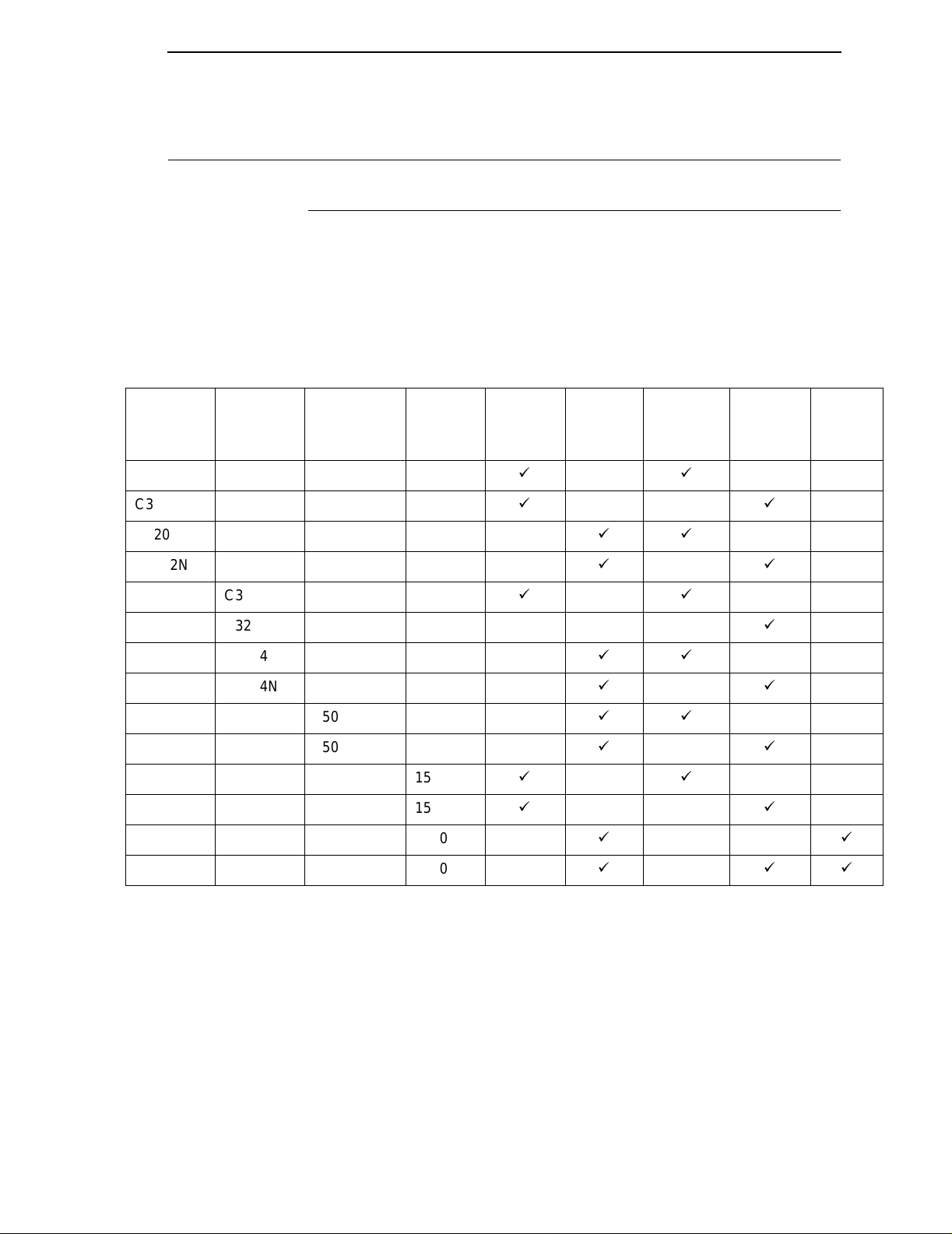
Table 1. The P5000LJ Series Printer Family
The Printronix P5000LJ Series Printer Family
Model
Number
US
C3201D C3201E 500P 500 lpm
C3201ND C3201NE 500P 500 lpm
C3202D C3202E 500Q 500 lpm
C3202ND C3202NE 500Q 500 lpm
C3203D C3203E 1000P 1000 lpm
C3203ND C3203NE 1000P 1000 lpm
C3204D C3204E 1000Q 1000 lpm
C3204ND C3204NE 1000Q 1000 lpm
C3205D C3205E 1500Q 1500 lpm
C3205ND C3205NE 1500Q 1500 lpm
C3206D C3206E 1500P 1500 lpm
C3206ND C3206NE 1500P 1500 lpm
C5640D C5640E 1500QS 1500 lpm
Model
Number
Europe
Nameplate
Print
Speed
Serial/
Pedestal Cabinet
Parallel
Interface
Serial/
Ethernet
Interface
Power
Stacker
C5640ND C5640NE 1500QS 1500 lpm
Most line matrix printers have specialized architectures which enable the
printer to emulate, or behave like, another printer. These specialized
architectures are restricted. The P5000LJ printer, however, introduces an
open architecture concept that is not available on any other line matrix printer.
The P5000LJ printer offers the standard emulation of Hewlett-Packard's
Printer Control Language, PCL Level II, to allow easy online programming
capabilities and compatibility with Hewlett-Packard systems. The Printronix
P5000LJ Series printers are fully compatible with HP LineJet and LP Series
printers.
19
Page 20
Chapter 1 Printer Overview
Additionally, the P5000LJ printer offers the following three emulations as part
of its LinePrinter Plus grouping: Proprinter
®
III XL, Epson® FX-1050, and
Serial Matrix P-Series. No matter what emulation is configured, your printer is
very easy to use. The message display and indicator on the control panel
communicate with you directly and clearly. You can select every function on
your printer at the control panel, or you can send commands from the host
computer.
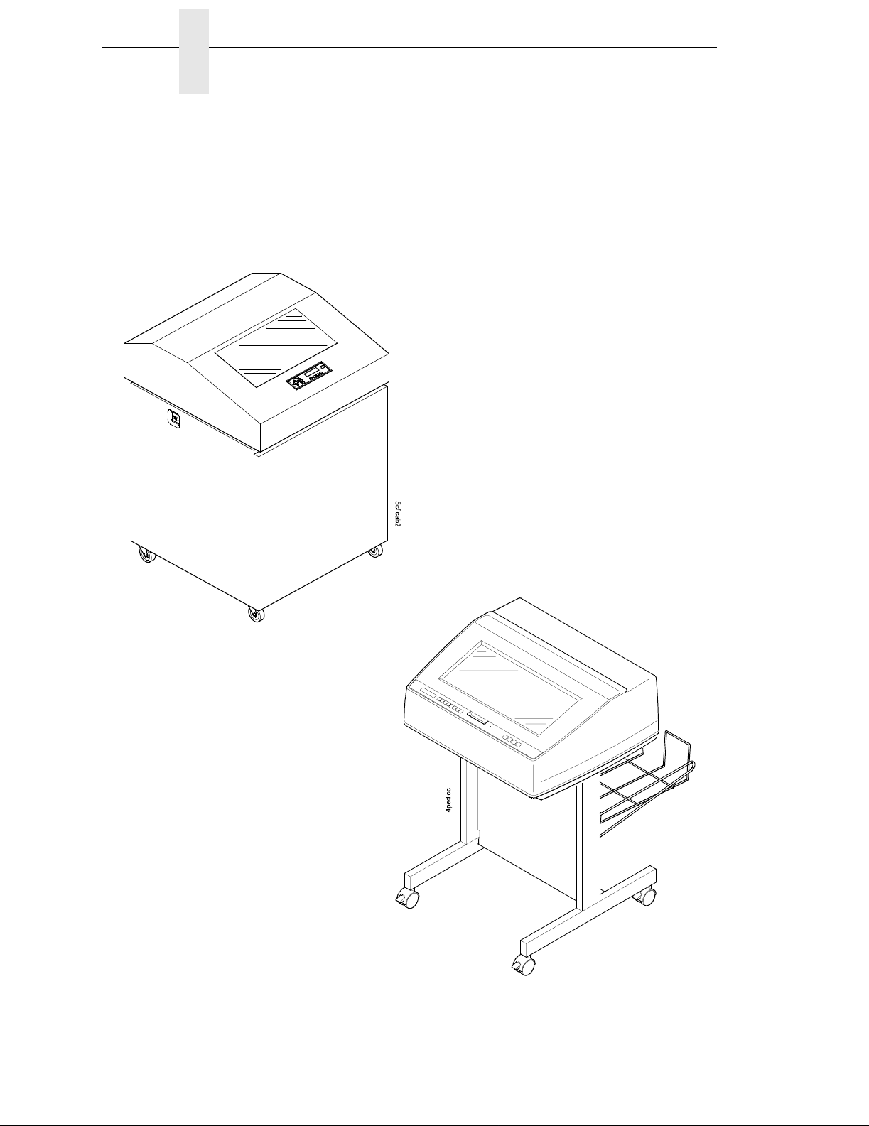
500Q
1000Q
1500Q
1500QS
20
P5000LJ
500P
1000P
1500P
Figure 1. The P5000LJ Printers
Page 21

Taking Care Of Your Printer
Taking Care Of Your Printer
Your printer will produce high quality print jobs if it is well taken care of.
Periodic cleaning, handling the printer properly, and using the correct printer
supplies, such as paper and ribbons, will ensure optimum performance.
Chapter 16 explains how to clean the printer, and printer supplies are listed in
Appendix A.
Whenever it is necessary to service the printer, remember these important
maintenance concepts:
• Use only the ribbons specified in Appendix A. Use of incorrect ribbons
can cause ink migration problems, degraded print quality, and expensive
damage to the printer.
• Incorrect closure of the forms thickness lever can cause smearing,
degraded print quality, paper jams, and damage to the platen and shuttle
assembly. Never close the forms thickness lever too tightly.
• Excessive printing outside of the boundaries of the paper will degrade
print quality and cause hammer bank damage. Never print outside of the
paper width.
St andard Fea tures
All of the printers offer a wide range of horizontal and vertical dot densities,
operate quietly, and can load an emulation very easily. Other features are
specified in the following secti ons.
Host Computer Interfaces
The following host computer interface choices are available:
• Bi-Tronics
• RS-232 serial interface
• RS-422 serial interface
• Centronics
• Ethernet™ (optional on 500P and 500Q only)
Printer Emulations
The following printer emulations (or protocols) are selectable at the control
panel:
• HP
• LP Plus, which consists of:
®
Printronix P-Series
Epson FX-1050
IBM
®
®
PCL-II (the default)
®
Proprinter III XL
• QMS (optional)
• PGL (optional)
Each emulation provides a different set of configuration menus, control codes,
and character sets.
21
Page 22

Chapter 1 Printer Overview
Output Control
Depending on the active emulation, the printers have the following output
control features:
• Four modes for printing text:
1. Correspondence (High Density)
2. Data Processing (DP) (Standard Density)
3. Sparse (high speed) (Sparse Density)
4. OCR A and OCR B
• Selectable forms length and width
• Character attribute specification:
1. Selectable pitch: normal, expanded, and compressed
2. Emphasized (shadow) printing
3. Automatic underlining and overscoring
4. Superscript and subscript printing
5. Double high and wide printing
• Resident multinational cha ra cte r sets and bar code s
Graphics and V ertical Form atting
Several graphics and vertical formatting features are available:
• Built-in graphics genera tors :
1. IBM Proprinter III XL bit-image graphics
2. Epson FX-1050 dot graphics mode
3. P-Series Plot
4. PCL raster graphics
• Programmable electronic vertical formatting provides rapid vertical paper
movement to specified lines for printing repetitive and continuous forms.
You can choose from the following methods:
1. Vertical tabbing in Proprinter III XL and Epson FX emulation modes
2. Electronic Vertical Format Unit (EVFU) in P-Series emulation mode
3. PCL vertical forms control (VFC)
Built-in Diagnostic Tools
The following diagnostic tools are provided with the printer:
• Comprehensive diagnostic self-tests permanently stored in the printer
• Configuration printout
22
• Data stream hex code printout
• Symbol set printout
Page 23

Graphics Options
Graphics Options
The PGL and VGL emulations allow you to create and store forms; generate
logos, bar codes, and expanded characters; and create other graphics.
Alphanumerics and bar code data are added as the form is printed.
Protocols And Emulations
A protocol is a set of rules governing the exchange of information between the
printer and its host computer. These rules consist of codes which manipulate
and print data and allow for machine-to-machine communication. A printer
and its host computer must use the same protocol.
Most impact printers use single ASCII character codes to print text, numbers,
and punctuation marks. Some characters, both singularly and in groups of two
or more, are defined as control codes. Control codes instruct the printer to
perform specific functions, such as underlining text, printing subscripts,
setting page margins, etc. The main difference between most printer
protocols is in the characters used to create control codes and the ways in
which these characters are formatted.
When the printer executes the character and control codes of a particular
printer protocol, it is “emulating” that printer. For example, if the printer uses
the Proprinter III XL protocol, it is emulating an IBM Proprinter III XL printer; if
the printer is using the Epson FX-1050 printer protocol, it is in Epson FX-1050
emulation mode. As used in this manual, “protocol” and “emulation” mean the
same thing.
23
Page 24

Chapter 1 Printer Overview
Line Matrix Printing
Your printer is an impact printer; it creates characters by printing ink dots on
paper. The dots are printed on an invisible matrix mapped in printer memory
(see Figure 2). Dot impressions are made by an array of steel hammers
mounted on a rapidly oscillating shuttle. The hammers strike the paper
through a moving ink ribbon.
Dot Row
Dot Column
Matrix visible only to
the printer
Ink dots formed by
hammer tips.
Serial matrix printers use a moving printhead with pins to form single
characters sequentially along the printed line. Unlike serial matrix printers, the
P5000LJ printer is a line matrix printer. Line matrix printers divide every
printable line into horizontal dot rows, then print a dot row of the entire line at
every lateral sweep of the shuttle.
During each sweep, hammers are activated to print dots at the required
positions in the dot row. When the shuttle reache s the end of a sweep, it
reverses direction, the paper advances one dot row, and the hammers print
the next row of dots as the shuttle sweeps in the opposite direction, as shown
in Figure 3.
Character Row
Character Column
Figure 2. Dot Matrix Character Formation
24
After a line of characters is printed, the paper advances to the first dot row of
the next print line. This creates a number of blank rows between lines of
characters, depending on the print mode and line spacing you selected.
Page 25
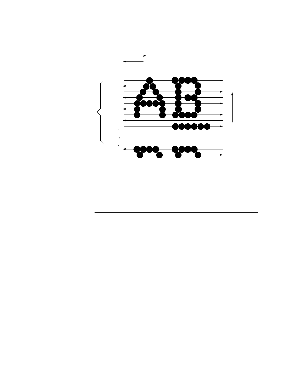
One
Text
Line
Dot
Row Start
1
2
3
4
5
6
7
8
*
9
**
10
11
Number of rows is determined by line spacing.
n
1
2
Printing Speed
Direction of Shuttle Movement
Paper
Feed
Direction
This row is used only for lowercase descenders.
*
This row is used for underlining and lowercase descenders.
**
Figure 3. Dot Matrix Line Printing
Printing Speed
The speed at which text prints is measured in lines per minute (lpm). This
speed is directly proportional to the number of dot rows required to produce a
character line, regardless of the number of characters in the line. More dot
rows are required to print lowercase characters with descenders;
consequently, those character lines print at a fractionally lower rate.
The printer also prints dot-addressable graphic images. The speed at which
graphics are plotted is measured in inches per minute (ipm). Unidirectional
plotting produces slightly better print quality and takes about twice as long as
bidirectional plotting. You can select either plotting mode from the control
panel.
Printing and plotting rates also vary according to the print mode you select.
Print mode refers to the way you instruct the printer to create characters. If,
for example, you select standard quality (data processing) mode, the printer
uses more dot rows to form characters than if you choose Sparse (high
speed) mode. Character formation and print speed are faster in Sparse mode,
because the printer prints fewer dot rows to form characters. Vertical dot
density is a factor in printing speed.
Nominal printing rates are charted in Appendix A.
25
Page 26

Chapter 1 Network Interface Card (NIC)
Network Interface Card (NIC)
Network Interface Card (NIC) allows you to attach printers on a local area
network (LAN) rather than attaching them directly to a host system. Following
simple configuration steps, these peripherals can be simultaneously shared
with users on the network whether you are using TCP/IP, NetBIOS over TCP/
IP, or IPX (Novell
NIC contains a network interface card to attach itself and the printer to the
network. This Ethernet™ 10/100Base-T interface connector is what allows the
printer to communicate with the network, and the interface itself has a number
of options, status indicators, and switches which are described in “NIC” on
page 27.
What Special Features Are Available?
NIC offers an extensive list of features including:
• built-in HTML forms for easy cross-platform configuration
).
• availability of printer manager software
• a detailed and easy-to-use command shell built in to the firmware
• multi-level configuration security through passwords, permission levels,
and access lists
• Wide Area Network (WAN) communication access
• numerous printer logging methods (e.g., automatic email) to record
printer errors and usage
• remote management through HTML forms, Telnet sessions, rsh/
rcmd/remsh
commands, SNMP, and pre-defined log methods
• extensive built-in troubleshooting tools
• built-in telnet and ping clients
• configurable memory usage by disab ling pr otoc ols and destination
services
• multiple destinations/queues for versatile printer manipulation and distinct
print setups
• header and trailer strings to instruct printers on font, pitch, printing, etc.
• flexible naming conventions
• automatic network connection and frame type sensing
• simultaneous printing across all I/O ports and all supported protocols
26
• multiple network protocol support
Page 27
NIC
NIC
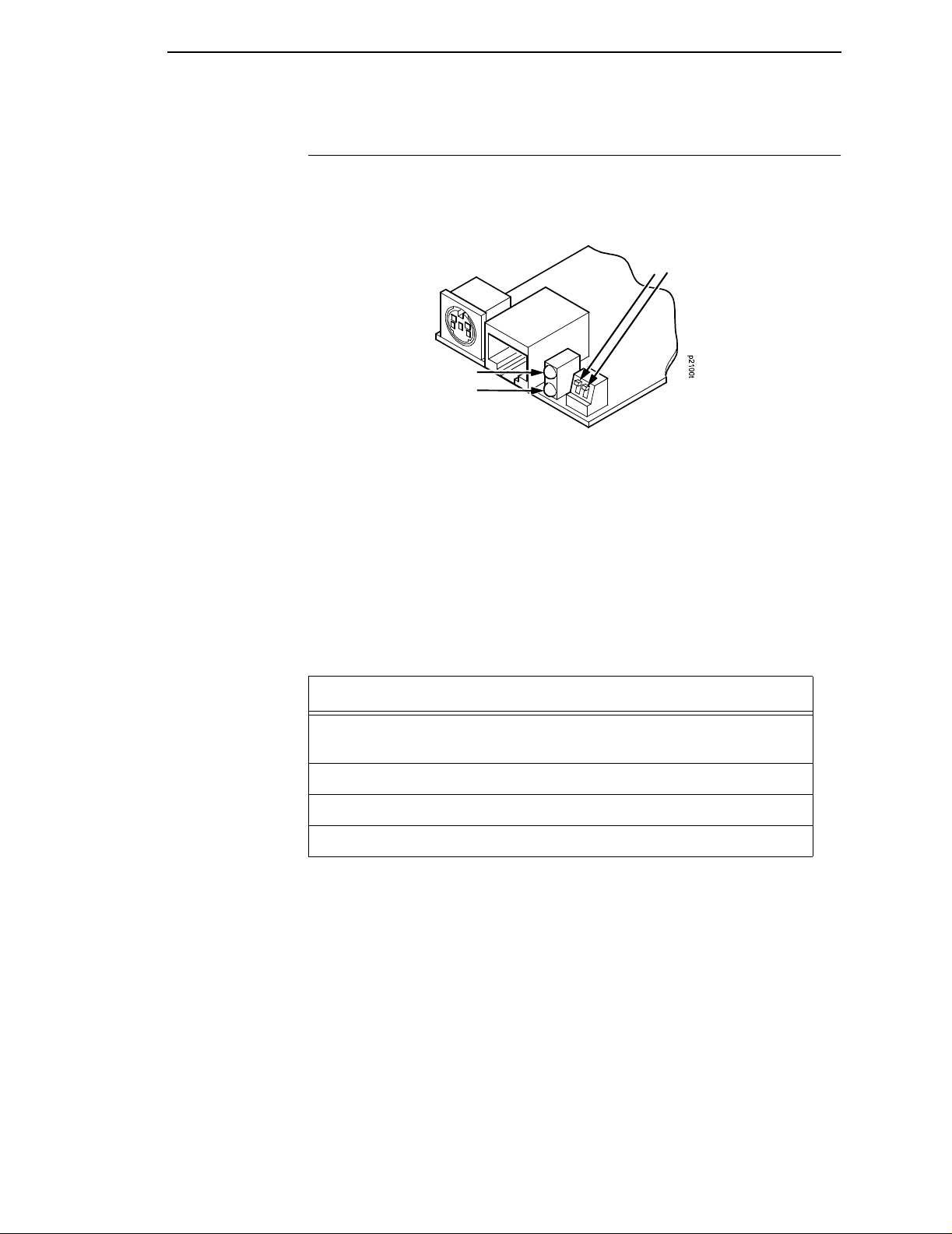
The NIC at the rear of the printer has two indicator lights and two dipswitches,
as shown in Figure 4.
Dipswitches
Shown in OFF
2
1
(default) position
STAT (System Status)
NET (Data to Network)
Figure 4. Status Indicator Lights and Dipswitches
Run and Auto Reset Modes
Run Mode is the normal operating state of NIC. Auto Reset mode is entered
when the watchdog timer is triggered and the Print Server resets itself. In
either mode, the STAT LED flashes at a varying rate, depending on whether
the unit IP address is configured. The Run Mode and Auto Reset Mode
indicator descriptions are given in Table 2.
Table 2. Indicator Modes
STAT Indication Description
OFF flashes on once per second Normal Mode, IP address
configured
OFF flashes on twice per second IP address not configured
ON flashes off once per second Download (MOS)
ON flashes off twice per second Error
27
Page 28
Chapter 1 Network Interface Card (NIC)
Network Indicator
The NET LED displays the status of the network link. When the NET LED is
on, link integrity is confirmed. The NET LED flashes off for 1/3 second when a
data packet is being transferred. When the NET LED is off, the network
connection has been severed.
Dipswitches
On the back of the interface, you will find a small window where you can
access two dipswitches labeled 1 and 2 (see Figure 4). The functions of the
dipswitches are explained in Table 3.
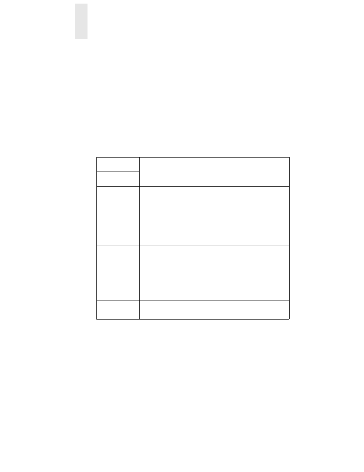
Table 3. Dipswitch Functions
Dipswitch
12
Comments
OFF OFF Normal operation. With both dipswitches in the OFF
position, the NIC boots up using the settings in flash
memory rather than the default settings.
ON OFF Factory default settings. With the dipswitches in this
configuration, the NIC boots up and erases all settings
stored in flash memory except the Ethernet address
and key value.
OFF ON Default IP. With the dipswitches in this configuration,
the NIC boots up with factory default settings.
However, the stored settings in flash memory are
intact. Setting dipswitch 2 to ON does not clear any
settings stored in flash memory ; inste ad, it boots the
unit with the IP settings in flash memory temporarily
ignored.
ON ON Reserved. This dipswitch setting is not for customer
use.
28
Page 29

2 Downloading Function
Introduction
Code In P5000LJ Series
Printers
Downloading the function code is equivalent to updating firmware in the
printer. This chapter explains how to load function code into P5000LJ printers.
You must download function code when:
• you require upgraded firmware for maintenance or other reasons;
• the CMX controller board is replaced;
• the flash memory SIMM is replaced;
• the NIC is installed or replaced;
• you need different emulation software or buy the VGL or PGL graphics
option after the printer is installed.
Downloading In A Nutshell
Updating the function code in a P5000LJ printer consists of three tasks:
1. Obtaining the appropriate download file and loading it into the PC or
laptop you will use to download the code into the printer.
2. Obtaining the appropriate interface cable if necessary.
3. Printing all saved configurations in the printer, making the function code
upgrade, and restoring your saved printer configurations.
29
Page 30

Chapter 2 Introduction
Preparation For Downloading
There are several function code files available for the P5000LJ printers. The
file you use depends on the printer emulation in use.
Note Always upgrade the function code to the latest version available that meets
the minimum flash memory and DRAM SIMM sizes listed in Table 4.
To verify what function code is already installed, observe the control panel
display when the printer is online. If a configuration printout is available, the
function code file version is printed at the top of the configuration printout on
the line that begins “Program File Version.” For example, if the line is
“Program File Version (2.07P Part No. 356351), the number “356351” is the
function code download file active at the time the configuration printout was
generated.
You can download function code from a networked PC or laptop computer
which contains the function code. If the printer has the NIC installed, the
function code must be updated via the network to successfully update the NIC
firmware. Loading function code via the network is done using the Printronix
Remote Management (RMS) software available on the PrintNet Enterprise
CD or using the file transfer protocol (ftp) procedure.
30
Page 31

Preparation For Downloading
Table 4. P5000LJ Series Printers Function Code Chart
Description
If Serial or Parallel Connected
Printers using
PCL-II emulation
Printers using
VGL emulation
Printers using
PGL emulation
If Network Connected
Printers using
PCL-II emulation
Printers using
VGL emulation
Printers using
PGL emulation
* ONLINE - SERL / PCL II or ONLINE - SERL / LP PLUS if serial port is the selected host interface
1 If the internal network card is not installed or was removed, download via the parallel or serial port. If the printer
Function Code is downloaded with the NIC removed, or a NIC card is added to the printer after downloading, the
Ethernet port will not function with RMS. In this case, do the following:
1. Press the up/down/right/left arrow keys simultaneously. Printer displays “FACTORY / Printer Management.”
2. Press the down arrow key. Printer displays “Diagnostic Port.”
3. Press the down arrow key. Printer displays “Debug Serial.”
4. Press the right arrow key. Printer displays “Debug Ethernet.”
5. Press ENTER. Printer displays “Debug Ethernet*.” Press ONLINE to exit.
Control Panel Displays:
(Emulation in Use)
ONLINE-PARL / PCL II* (or)
ONLINE-PARL / LP PLUS*
ONLINE-PARL / PCL II / VGL*
ONLINE-PARL/LP PLUS/PGL*
ONLINE-ETHERNET / PCL II (or)
ONLINE-ETHERNET / LP+
ONLINE-ETHERNET / LP+ (or)
ONLINE-E-NET / CODE V / PCL
ONLINE-ETHERNET/PGL/LP+ (or)
ONLINE-ETHERNET/PCL-II
NOTES
Download
File (as
shipped)
xxxxxx.exe
(Note 2)
xxxxxx.exe
(Note 2)
xxxxxx.exe
(Note 2)
xxxxxx.exe
(Note 2)
xxxxxx.exe
(Note 2)
xxxxxx.exe
(Note 2)
Download
Method
Parallel or
Serial Port
Parallel or
Serial Port
Parallel or
Serial Port
Via Network
(Note 1)
Via Network
(Note 1)
Via Network
(Note 1)
Minimum
Flash/DRAM
Required
4 MB Flash
4 MB DRAM
4 MB Flash
4 MB DRAM
4 MB Flash
4 MB DRAM
4 MB Flash
4 MB DRAM
4 MB Flash
4 MB DRAM
4 MB Flash
4 MB DRAM
2 Check with T echnical Support, (Customer Service Center) to confirm the latest available Function Code
download file.
Copying Function Code T o Your Computer
In order to download function code to a printer if using a serial or parallel port,
the function code file must reside in a PC or laptop computer running any of
the following operating systems: MS-DOS
Windows 95/98, Windows NT or Windows 2000.
Note that the downloaded file, xxxxxx.exe, is a compressed executable file.
Leave the file as it is. Do not try to execute the file.
®
, PC-DOS™, or DOS session on
31
Page 32

Chapter 2 Loading Function Code To Flash Memory In The Printer
Loading Function Code T o Flash Memory In The Printer
This section contains two loading techniques:
• How to load function code through the parallel or serial port of the printer.
• How to load function code through the Ethernet port using the file transfer
protocol (ftp).
Note If Ethernet is installed, you must install the code through the Ethernet port
using ftp.
Installing Printer Emulations
Printer emulation software is stored in flash memory. Flash memory is
contained in single in-line memory modules (SIMMs) located on the controller
board. Printer emulation and operating system software are loaded into flash
memory at the factory, but you will install software in some situations:
• A printer software upgrade is installed
• The printer controller board has been replaced
• The flash memory SIMM has been replaced
Emulation and operating system software are stored on a CD. You will copy
the appropriate file to your computer’s hard disk, then download that file to the
printer.You can load software through the serial, parallel, or Ethernet NIC port
of the printer:
Note Each printer type, line matrix, laser, and thermal has its own CD with the
specific file types for that printer. Be sure to use the appropriate CD for
your printer type when downloading software.
Note When downloading emulation and operating system software to the
printer, all other optional font files, customer-supplied logos, setup files,
and TIFF files will be erased. You will then need to reload those files.
Before starting a download procedure, be sure that you have all the
necessary files on hand.
32
Page 33

Downloading Software Through the Serial or Parallel Port
• Serial or Parallel Port: If you are going to load memory through the
serial or parallel port of the printer, see “Downloading Software Through
the Serial or Parallel Port” on page 33.. The load commands are different,
depending on the printer port you use. These differences are explained in
the note following step 22., page 36.
• NIC: If the printer has the NIC installed, see “Downloading Software
Through the Network Interface Card (NIC)” on page 37.
• Font Files: If you need to load optional font files, see “Downloading
Optional Font Files to Flash Memory” on page 39.
Downloading Softwa re Through the Serial
or Parallel Port
1. Make a printout of all saved configurations. (Installing new software
erases all saved configurations. You will use the printouts to restore the
printer configurations.)
2. Set the printer power switch to O (Off).
3. If the printer is already connected to the serial or parallel port of an
IBM-compatible computer running the PC-DOS™ or MS-DOS operating
system, go to step 9. If not, go to step 4.
4. Unplug the AC power cord from the printer.
5. Disconnect all data input cables from the printer interfaces.
6. Connect a parallel data cable to the LPT1 port or a serial data cable to the
COM1 port of an IBM-compatible computer running the PC-DOS or
MS-DOS operating system.
Note You can connect the cable to the LPT2 port if the LPT1 port is already in
use. The load commands are different if you use this port, as described in
the note after step 22.
7. Connect the data cable to the appropriate I/O port of the printer.
8. Plug the AC power cord into the printer.
9. On the printer control panel, press and hold down the ONLINE + PAPER
ADVANCE keys. Without releasing the keys, power the printer on.
Continue holding down the keys.
10. When you see “TESTING HARDWARE PLEASE WAIT” on the LCD,
release the keys.
11. Wait until you see “WAITING FOR PROGRAM DOWNLOAD” on the LCD
before proceeding. This can take up to 30 seconds to appear, depending
on the emulations and interfaces installed in the printer.
12. Press the
PORT=CENTRONICS” appears on the LCD.
⇒ (NEXT) key. “SELECT DOWNLOAD
33
Page 34

Chapter 2 Installing Printer Emulations
Note The default port is CENTRONICS; this is the standard load through the
parallel port. If you want to use the default, continue at step 14.
13. Press
14. When the printer download port you want to use is displayed on the LCD,
15. Using Windows Explorer, create a directory named download at the root
16. Insert the printer emulation software CD into your computer.
⇒ (NEXT) again to cycle through the download ports available in
the printer:
RS232-9600 (RS-232 serial, 9600 baud)
RS232-19.2K (RS-232 serial, 19200 baud)
RS232-38.4K (RS-232 serial, 38400 baud)
RS232-115K (RS-232 serial, 115000 baud)
RS422-9600 (RS-422 serial, 9600 baud)
RS422-19.2 (RS-422 serial, 19200 baud)
RS422-38.4K (RS-422 serial, 38400 baud)
RS422-115K (RS-422 serial, 115000 baud)
DEBUG
press the ENTER key. “WAITING DOWNLOAD / PORT = <your
selection>” appears on the display.
level of your C: hard drive.
34
Figure 5. Navigating to the Appropriate Emulation File on the CD
Page 35

Downloading Software Through the Serial or Parallel Port
17. Using Windows Explorer, navigate to the appropriate file on the CD based
on the printer model number and desired emulation, e.g., T5000
(See Figure 5.)
18. Make note of the file name, which is a six digit number plus .exe,
e.g., 123456.exe.
This is the file you will download into the printer.
IGP.
Figure 6. Copying the Emulation File to the Download Directory
19. Copy the file to the download directory.
Note You may need to hold Ctrl to make sure a + appears to the right of the
pointer. (See Figure 6.)
20. Start a command prompt session. (The Start Menu icon is usually labeled
MS-DOS Prompt or Command Prompt.)
21. At the command prompt type:
C:<Enter>
cd \download<Enter>
35
Page 36

Chapter 2 Installing Printer Emulations
22. At the command prompt on the computer type:
filename.exe -pb<Enter>
where filename.exe is the file name you noted in step 18. This command
decompresses the file on the hard drive and copies it as a binary file into
the flash memory on the printer controller board.
Note If you are loading the file using the LPT2 port on the computer, enter the
following command:
filename.exe -pb2 <Enter>
The 9600 baud rate is the only selection older versions of MS-DOS can
use. The baud rate information entered in the following commands must
match the selection you made in step 13.
If you are loading the file through the printer serial port, enter the following
commands:
mode COM1:9600,N,8,1,P<Enter>
filename.exe -pbc1<Enter>
Caution Do not interrupt the downloading process once it has started.
Interrupting a download will damage the flash memory on the
controller board and the NIC.
While the file is copied into memory, the printer LCD informs you of the
load process and status.
23. When the new program has successfully loaded into memory and the
printer has reset itself, set the printer power switch to O (Off).
24. Unplug the AC power cord from the printer.
25. Remove the CD from the host computer and store it with the printer.
26. Power off the computer.
27. If you had to install a data cable to the computer and printer in step 6.,
disconnect it from the computer and printer.
28. If required, reconnect the data input cable(s) to the printer.
Using the configuration printout(s) you made in step 1., reconfigure the printer
and reload any optional font files.
36
Page 37

Downloading Software Through the Network Interface Card (NIC)
Downloading Softwa re Through the
Network Interface Card (NIC)
1. Make a printout of all saved configurations. (Installing new software
erases all saved configurations. You will use the printouts to restore the
printer configurations.)
2. Set the printer power switch to O (Off).
3. On the printer control panel, press and hold down the ONLINE + PAPER
ADVANCE keys. Without releasing the keys, power the printer on.
Continue holding the ke ys down.
4. When you see “TESTING HARDWARE PLEASE WAIT” on the LCD,
release the keys.
5. Wait until you see “WAITING FOR PROGRAM DOWNLOAD” on the LCD
before proceeding. This can take up to 30 seconds to appear, depending
on the emulations and interfaces installed in the printer.
6. Using Windows Explorer, create a directory named download at the root
level of your C: hard drive.
7. Insert the printer emulation software CD into your computer.
Figure 7. Navigating to the Appropriate Emulation File on the CD
8. Using Windows Explorer, navigate to the appropriate file on the CD (using
the Unzipped directory) based on the printer model number and desired
emulation, e.g., Unzipped
T5000IGP. (See Figure 7.)
37
Page 38

Chapter 2 Installing Printer Emulations
Note You must use the Unzipped directory, since this contains the
uncompressed files necessary for NIC download.
9. Make note of the file name, which is a six digit number plus .prg,
e.g., 123456.prg.
This is the file you will download into the NIC.
10. Copy the file to the download directory.
11. Start a command prompt session. (The Start Menu icon is usually labeled
MS-DOS Prompt or Command Prompt.)
12. At the command prompt type:
C:<Enter>
cd \download<Enter>
13. Start the FTP protocol by typing:
ftp xxx.xxx.xxx.xxx<Enter>
(where xxx.xxx.xxx.xxx represents the IP Address of the printer.)
14. Log in to the printer by typing:
root<Enter>
You are given a password prompt.
Note The default is no password. If the FTP program requires a password,
contact your system administrator.
15. At the password prompt, press <Enter>.
16. Once logged in, type the following sequence at the command prompt to
download the filename.prg file to the printer:
cd dest<Enter>
cd d1prn<Enter>
bin<Enter>
put filename.prg<Enter>
(where filename.prg is the file name you noted in step 9.)
Caution Do not interrupt the downloading process once it has started.
Interrupting a download will damage the flash memory on the
controller board and the NIC.
38
17. As the file downloads, the FTP program shows the progress as a
percentage. Once the download is complete, exit out of the FTP program
by typing:
quit<Enter>
Page 39

Downloading Optional Font Files to Flash Memory
18. When the new program has successfully loaded into flash memory and
the printer has reset itself, set the printer power switch to O (off).
19. Unplug the AC power cord from the printer.
20. Remove the CD from the host computer and store it with the printer.
21. Using the configuration printout(s), reconfigure the printer and reload any
optional font files.
Downloading Optional Font Files to Flash Memory
Optional font files are stored on a 3.5 inch floppy diskette that contains file
names comprised of a part number with a .dwn extension. You will insert the
diskette in your IBM-compatible computer and use either the parallel or serial
port to download the desired font file(s) to the printer’s flash memory.
1. Set the printer power switch to O (off).
2. Connect a parallel data cable to the LPT1 port or a serial cable to the
COM1 port of an IBM-compatible computer running the PC-DOS or
MS-DOS operating system.
Note You can connect the cable to the LPT2 port on the computer if the LPT1
port is already in use. The load commands are different if you use this port,
as described in the notes after step 15.
3. Verify that the data cable is connected to the appropriate I/O port on the
printer and to the host computer.
4. Power on the computer and allow it to boot up.
5. On the printer control panel, press and hold down the ONLINE + PAPER
ADVANCE keys while powering the printer on. Continue holding the keys
down.
6. When you see “WAITING FOR PROGRAM DOWNLOAD” on the LCD,
release the keys.
Note The printer default port is CENTRONICS; if you want to use this port,
continue to step 15.
7. Press the
CENTRONICS” appears on the LCD.
⇒ (NEXT) key; “SELECT DOWNLOAD PORT =
39
Page 40

Chapter 2 Installing Printer Emulations
8. Press the
available in the printer:
RS232-9600 (RS-232 serial, 9600 baud)
RS232-9600 (RS-232 serial, 19200 baud)
RS232-9600 (RS-232 serial, 38400 baud)
RS232-9600 (RS-232 serial, 115000 baud)
RS422-9600 (RS422 serial, 9600 baud)
RS422-9600 (RS422 serial, 19200 baud)
RS422-9600 (RS422 serial, 38400 baud)
RS422-9600 (RS422 serial, 115000 baud)
DEBUG
9. When the printer download port you want to use is displayed on the LCD,
press the ENTER key. “WAITING DOWNLOAD / PORT” = <your
selection> appears on the display.
10. Insert the optional font diskette into diskette drive A (or B) of the
computer.
11. Start a command prompt session. (The Start Menu icon is usually labeled
MS-DOS Prompt or Command Prompt.)
12. Make the diskette drive the active drive by typing:
A:<Enter> (if the diskette is in drive B, type B:<Enter>)
13. List the contents of the diskette at the command prompt by typing the
following:
⇒ (NEXT) key again to cycle through the download ports
dir<Enter>
You will see a directory listing containing files with a .dwn extension, e.g.,
94021.dwn, 94022.dwn, 94023.dwn .
14. Make note of the file name with the .dwn extension of each file you want
to download to the printer.
Note The numeric portion of the file name will match the numbers of the font
typefaces listed in Appendix E of the PGL and VGL Programmer’s
Reference Manuals and provide you with a description and print sample of
the typeface.
15. At the command prompt type:
copy /b filename.dwn LPT1<Enter>
(where filename.dwn is file name you noted in step 14.)
40
Page 41

Downloading Optional Font Files to Flash Memory
Note If you are loading the file using the LPT2 port on the computer, type the
following command:
copy /b filename.dwn LPT2<Enter>
(where filename.dwn is a file you noted in step 14.)
If you are loading the file using the serial port on the computer,
type the following commands:
mode COM1:9600,N,8,1,P<Enter>
copy /b filename.dwn COM1<Enter>
(where filename.dwn is a file you noted in step 14.)
The 9600 baud rate is the only selection older versions of MS-DOS can
use. The baud rate information entered in the above commands must
match the selection you made in step 8.
You can download the optional font files one at a time by entering one file
name per the copy command or you can copy multiple files in one copy
command.
To download one file at a time, enter the following at the command
prompt:
copy /b filename.dwn LPT1<Enter>
To download multiple files, enter the following at the command prompt,
for example:
copy /b filename1.dwn+filename2.dwn+...LPT1<Enter>
16. While the font file is copied into flash memory, the printer LCD informs
you of the load process and status. When the new file is successfully
loaded into memory, the printer will reset itself and go online.
17. To verify that the optional fonts have been downloaded:
a. Perform a configuration print out.
— OR —
b. Select MAINT/MISC
names will appear with the same part number file name you
downloaded, but with an .sf extension.
Note The optional font typefaces cannot be selected via the printer control
panel. They can only be selected via a software command from the host.
File SystemsView Files List. The new file
Note Press the ONLINE key to place the printer online and return the printer to
normal operation.
41
Page 42

Chapter 2 Installing Printer Emulations
T a ble 5. Flash Memory Message Guide
Message Explanation Required Action
CLEARING PROGRAM
FROM FLASH
DIAGNOSTIC PASSED The printer passed its
ERROR: DC PROGRAM
NOT VALID
ERROR: DRAM AT
ADDRESS XXXXXXXX
ERROR: EC PROGRAM
NOT VALID
The program successfully
loaded into printer RAM and
the checksum matched. The
old program is now being
deleted from flash memory.
memory and hardware
initialization tests.
Printer cannot find the data
controller program or the
validation checksum is
corrupt.
The printer found a defective
memory location.
Printer cannot find the engine
controller program or the
validation checksum is
corrupt.
None
None
1. Download the program
again.
2. If the message occurs
again, replace the flash
memory.
Replace the DRAM.
1. Download the program
again.
2. If the message occurs
again, replace the flash
memory.
ERROR: EC STOPPED AT
STATE XXXX
ERROR: FLASH DID NOT
PROGRAM
ERROR: FLASH NOT
DETECTED
ERROR: NO DRAM
DETECTED
ERROR: NVRAM FAILURE The non-volatile memory has
ERROR: PROGRAM NEEDS
MORE DRAM
Hardware fault in the engine
controller.
The printer could not find any
flash memory.
The printer could not find any
flash memory.
The printer could not find any
DRAM.
failed.
The printer requires more
DRAM memory in order to run
the downloaded program.
Replace the CMX controller
board.
1. Download the program
again.
2. If the message occurs
again, replace the flash
memory.
Install flash memory before
attempting to download this
program.
Check DRAM on CMX. If
present, reseat DRAM, If
missing, install DRAM.
Replace the CMX controller
board. (Do NOT attempt to
replace NVRAM.)
Add DRAM or use a smaller
emulation program.
42
Page 43

Downloading Optional Font Files to Flash Memory
T a ble 5. Flash Memory Message Guide (continued)
Message Explanation Required Action
ERROR: PROGRAM NEEDS
MORE FLASH
ERROR: PROGRAM NOT
COMPATIBLE
ERROR: PROGRAM NOT
VALID
ERROR: SECURITY PAL
NOT DETECTED
ERROR: SHORT AT
ADDRESS XXXX
ERROR: WRITING TO
FLASH
The printer requires more
flash memory in order to run
the downloaded program.
The printer is not compatible
with the downloaded
program.
The printer does not see a
program in flash memory.
The security PAL is not
present or has failed.
Hardware failure in DRAM or
CMX controller circuitry.
Hardware or software fault in
flash memory.
Add flash memory or use a
smaller emulation program.
Use the correct emulation
software option(s) for this
model.
There is no program in printer
memory. Download the
program again.
Check the security PAL at
location U54 on the CMX
controller. If the PAL is
absent, install correct PAL. If
security PAL is present,
replace the CMX controller
board.
Replace DRAM. If message
occurs with new DRAM,
replace CMX controller board.
1. Download the program
again.
ERROR: WRONG
CHECKSUM
ERROR OCCURRED
FLUSHING QUEUES *
LOADING PROGRAM FROM
PORT XX%
The printer received the
complete program but the
checksum did not match. The
data were corrupted during
download.
An interim message that
displays while the printer
discards host data it cannot
use because a fault condition
exists. While this message
displays, the asterisk (*)
rotates.
The new program is loading
into printer RAM. XX
indicates how much of the
program has loaded.
2. If the message occurs
again, replace the flash
memory.
Download the program again.
Wait. When the asterisk (*)
stops rotating, a different fault
message will appear:
troubleshoot the final
message.
None
43
Page 44

Chapter 2 Installing Printer Emulations
Table 5. Flash Memory Message Guide (continued)
Message Explanation Required Action
LOADING PROGRAM INTO
FLASH
PLEASE WAIT...RESET IN
PROGRESS
RESTORING BOOT CODE Norma l download initialization
SECURITY CODE
VIOLATION
SENDING PROGRAM TO
EC PROCESSOR
TABLE MISMATCH
DOWNLOAD AGAIN
The printer has deleted the
previous program from flash
memory and is loading the
new program into flash
memory.
The printer finished loading
the program into flash
memory and is automatically
resetting itself.
message.
The software running or being
downloaded does not match
the security PAL code.
The printer is loading the
engine controller program into
the engine controller.
EC software update in
process.
None
None
None
Install the correct PAL or
program. (PAL and program
must match.)
None
Download the program again.
44
Page 45

3 Configuring The Printer
Overview
Note Configuration directly affects printer operation. Do not change the
configuration of your printer until you are thoroughly familiar with the
procedures in this chapter.
This chapter is a tutorial that explains how to configure the P5000LJ printer
and the NIC.
Configuring The Printer
In order to print data, the printer must respond correctly to signals and
commands received from the host computer. Configuration is the process of
matching the printer's operating characteristics to those of the host computer
and to specific tasks, such as printing labels, or printing on different sizes of
paper.
The characteristics that define the printer's response to signals and
commands received from the host computer are called configuration
parameters.
A configuration consis ts of all the param eter s under the Acti ve Emul ati on,
Emulation, Maint/Misc., Host Interface, Printer Control, and Diagnostics
menus. Chapter 4 describes the configuration submenus and their
parameters in more detail.
You configure the printer by pressing keys on the control panel (Figure 8) or
by sending control codes from the host computer. This chapter explains how
to change parameters and save, print, and load configurations with the control
panel. All of the keys are described in detail in the P5000LJ Series Printers
Quick Reference Guide which is shipped with each printer.
45
Page 46

Chapter 3 Configuring The Printer
Cabinet Model
PREV
UP
DOWN
Message Display
CLEAR
SHIFT
SET TOF
NEXT
ENTER
PAGE L ADJ
L.P.I. ADJ
ON LINE
Pedestal Model
FF VIEW
LF
Status Indicator
Message Display
Secondary Keys
(Raise the printer cover
to access these keys.)
Prev
Set
TOF
L.P.I.
Clear
Shift
Adj
Enter
Page
L Adj
Up Down
Next
Figure 8. The Control Panels
Status Indicator
FF ViewOn Line LF
Primary Keys
46
Page 47

OFFLINE
CONFIG.
CONTROL
page 77
Load Config.
Save Config.
Print Config.
Delete Config.
Power-Up Config.
Protect Configs.
ETHERNET
PARAMS
page 125
IP Address
Gateway Address
Subnet Mask
MAC Address
Novell Protocol
NetBIOS Protocol
Novell Frame
PPM Port Number
PPM Port Timeout
Ethernet Speed
3
ACTIVE
EMULATION
page 79
PCL-II*
LP PLUS
IGP/PGL & LP+
IGP/VGL & LP+
PRINTER
CONTROL
page 127
Unidirectional
PMD Fault
Slow Paper Slew
Power Saver Time
1
EMULATION
page 80
PCL-II*
LP PLUS
IGP/PGL & LP+
IGP/VGL & LP+
Printer Tests
Test Width
Paper Out Dots
System Memory
Print Statistics
2
DIAGNOSTICS
page 129
MAINT/MISC
page 114
Hex Dump Mode
Power-up State
3
Display Language
3
Power Stacker
RIBBON
MINDER
page 132
New Ribbon
Ribbon Action
Ribbon Size
Ribbon Adjust
Fault Action
3
HOST
INTERFACE
page 115
Bi-Tronics*
Centronics
Serial
3
Ethernet
Auto Switching
1
Choices available are limited to the emulations
installed on the printer.
2
Appears only if LP Plus is the active emulation.
3
Appears only if installed.
Figure 9. Configuration Menu Overview
To view options, press: Down
Up
Next
Prev
To select an option, press ENTER.
To return to main menu, press
CLEAR.
To exit menu, press ON LINE.
* = Default Setting
47
Page 48

Chapter 3 Configuring The Printer
Operating Modes
The printer has two operating modes: online and offline. When the printer is
online, it is controlled by the host computer and prints data sent by the host
computer. When the printer is offline, communication with the host is
interrupted so you can load paper, change ribbons, or test and configure the
printer.
Activate configuration settings with the ENTER key, which enters your new
setting into printer memory. An asterisk (*) after a displayed setting shows it is
entered into memory.
If pressing ENTER to select a parameter produces no result, press DOWN to
move to the next lower level. For example, if you press ENTER while
CONFIG. CONTROL/ Print Config. displays, nothing will happen because
another level exists below this selection. Press DOWN and the “Current”
option displays. To cycle through the choices (Current, Factory, Power-Up,
etc.), press the NEXT or PREV keys. Press ENTER and the selected
configuration will print.
The Configurations
A configuration consists of a group of parameters, such as line spacing, forms
length, etc. Your printer contains the following configurations:
• The factory default configuration. It can be loaded, but cannot be altered.
All of the parameters and their values are listed on page 50.
• Eight configurations that you can customize for unique print job
requirements. Creating customized configurations is explained on
page 54.
Locking And Unlocking The ENTER Key
To make configuration changes, you must unlock the ENTER key. With the
printer offline, raise the printer cover and press the UP and DOWN keys
simultaneously. The LCD will show this message for about a second:
ENTER SWITCH
UNLOCKED
When you lock the ENTER key, your configuration settings are fixed and
cannot be altered. (Locking secures your settings.)
With the printer offline, raise the printer cover and press the UP and DOWN
keys simultaneously to lock the ENTER key. The LCD will briefly show this
message:
48
ENTER SWITCH
LOCKED
Page 49

Changing And Saving Parameter Settings
Changing And Saving Parameter Settings
You can change a parameter setting, such as line spacing or forms length, by
pressing keys on the control panel or by sending emulation control codes in
the host data stream.
When you change a parameter, it is active as long as the printer is on. This is
true whether you used the control panel or sent a control code from the host.
If you use the control panel, you can save the parameters as a customized
configuration. A configuration consists of a group of parameters. A saved
configuration will not be lost if you turn off the printer.
You can change a parameter with a control code, but to save the parameter
setting you must use the control panel.
Control codes override control panel parameters. For example, if you set the
line spacing to 6 lpi with the control panel, and application software later
changes this to 8 lpi with a control code, the control code setting overrides the
control panel setting.
The 8 lpi parameter is effective as long as the printer is on. If you turn off the
printer, the 8 lpi parameter will be erased. To save the parameter, you must
use the control panel and save it as a configuration.
You can save up to eight configurations.
Changing parameters is described on page 54, and saving configurations is
described on page 56.
49
Page 50

Chapter 3 Configuring The Printer
Factory Default Configuration Values
The factory default values are permanently stored in memory as a
configuration and cannot be modified or erased. The configuration values for
the Bi-Tronics parallel interface and NIC interface are displayed on the
following pages.
Bi-T ro nics Pa rallel Interface
ACTIVE EMULATION PCL-II
PCL-II
Primary Char. set
ID 0
Symbol Set Roman-8 [8U]
Pitch 10.00
Density Data Processing
Second Char. set
ID 0
Symbol Set Roman-8 [8U]
Pitch 10.00
Density Data Processing
Page Length Rep. Inches/Page
Max. Line Width 13.2 inches
Face, CPI Delay Enable
Graphics Density 60 DPI
Perforation Skip Disable
Display Functns Disable
Line Terminator
LF After CR Disable
CR After LF Disable
CR after FF Disable
CR After VT Enable
PTX Linefeed Disable
LPI Adjust 6 LPI
Page L./Lines 66 Lines
Page L./Inches 11.0 Inches
Config. Print
Symbol Set Print
Reset Cmd CFG Ld Power Up Config
LP PLUS
Printer Protocol
P-Series
Control Code 06 8.0 LPI
Control Code 08 Elongated
Define CR Code CR = CR
Auto LF Disable
Overstrike Enable
Define LF code LF = CR + LF
Select SFCC 1
EVFU Select Enable
Alt. Set 80-9F Control Code
Character Set
IBM PC
SFCC d command Even dot plot
CPI/LPI Select
Select CPI 10.0 CPI
Select LPI 6.0 LPI
Primary Subset ASCII (USA)
Extended Subset Code Page 437
50
Page 51

Font Attributes
Typeface Data Processing
Prop. Spacing Disable
Bold Print Disable
Italic Print Disable
Slashed Zero Disable
Page Format
Form Length
Abs. Length IN 11.0 inches
Abs. Length MM 279.4 mm
Funct. of lines 66 lines
Form Width
Abs. Width IN 13.6 inches
Abs. Width MM 345.4 mm
Function of CPI 136 characters
Margins
Left Margin 0 columns
Right Margin 0 columns
Bottom Margin 0 lines
Perforation Skip Disable
MAINT / MISC
Hex Dump Mode Disable
Power-up State Online
Display Language English
Power Stacker Enable
HOST INTERFACE
Bi-Tronics
Prime Signal Disable
TOF Action Reset
Buffer Size in K 1
PRINTER CONTROL
Unidirectional Disable
PMD Fault Enable
Slow Paper Slew Disable
Power Saver Time 15 min
DIAGNOSTICS
Printer Tests Shift Recycle
Test Width Full Width
Paper Out Dots 40 dots
System Memory x Megabytes
Print Statistics
On: x.x Hrs
Print: x.x Hrs
Print Strokes x
Print Lines x
11 inch Pages x
RIBBONMINDER
New Ribbon
Ribbon Action Disable
Ribbon Size 60 yards
Ribbon Adjust 0
Fault Action New Ribbon
Factory Default Configuration Values
51
Page 52

Chapter 3 Configuring The Printer
NIC Interface
ACTIVE EMULATION PCL-II
PCL-II
Primary Char. set
ID 0
Symbol Set Roman-8 [8U]
Pitch 10.00
Density Data Processing
Second Char. set
ID 0
Symbol Set Roman-8 [8U]
Pitch 10.00
Density Data Processing
Page Length Rep. Inches/Page
Max. Line Width 13.2 inches
Face, CPI Delay Enable
Graphics Density 60 DPI
Perforation Skip Disable
Display Functns Disable
Line Terminator
LF After CR Disable
CR After LF Disable
CR after FF Disable
CR After VT Enable
PTX Linefeed Disable
LPI Adjust 6 LPI
Page L./Lines 66 Lines
Page L./Inches 11.0 Inches
Config. Print
Symbol Set Print
Reset Cmd CFG Ld Power Up Config
LP PLUS
Printer Protocol
P-Series
Control Code 06 8.0 LPI
Control Code 08 Elongated
Define CR Code CR = CR
Auto LF Disable
Overstrike Enable
Define LF code LF = CR + LF
Select SFCC 1
EVFU Select Enable
Alt. Set 80-9F Control Code
Character Set
IBM PC
SFCC d command Even dot plot
CPI/LPI Select
Select CPI 10.0 CPI
Select LPI 6.0 LPI
Font Attributes
Typeface Data Processing
Prop. Spacing Disable
Bold Print Disable
Italic Print Disable
Slashed Zero Disable
Primary Subset ASCII (USA)
Extended Subset Code Page 437
52
Page 53

Page Format
Form Length
Abs. Length IN 11.0 inches
Abs. Length MM 279.4 mm
Funct. of lines 66 lines
Form Width
Abs. Width IN 13.6 inches
Abs. Width MM 345.4 mm
Function of CPI 136 characters
Margins
Left Margin 0 columns
Right Margin 0 columns
Bottom Margin 0 lines
Perforation Skip Disable
MAINT / MISC
Hex Dump Mode Disable
Power-up State Online
Display Language English
Power Stacker Enable
HOST INTERFACE
Ethernet
Buffer Size in K 1
ETHERNET PARAMS
IP Address xxx.xxx.xxx.xxx
Gateway Address xxx.xxx.xxx.xxx
Subnet Mask xxx.xxx.xxx.xxx
MAC Address hhhhhhhhhhhh
Novell Protocol Disable
NetBIOS Protocol Disable
Novell Frame Ethernet 802.2
PPM Port Number 3001
PPM Port Timeout 100 seconds
Ethernet Speed Auto Select
PRINTER CONTROL
Unidirectional Disable
PMD Fault Enable
Slow Paper Slew Disable
Power Saver Time 15 min
DIAGNOSTICS
Printer Tests Shift Recycle
Test Width Full Width
Paper Out Dots 40 dots
System Memory x Megabytes
Print Statistics
On: x.x Hrs
Print: x.x Hrs
Print Strokes x
Print Lines x
11 inch Pages x
RIBBONMINDER
New Ribbon
Ribbon Action Disable
Ribbon Size 60 yards
Ribbon Adjust 0
Fault Action New Ribbon
Factory Default Configuration Values
53
Page 54

Chapter 3 Changing Parameters
Changing Parameters
A configuration consists of several parameters. The factory configuration is
PCL-II emulation using the Bi-Tronics interface. You can keep this
configuration to print your jobs, or if your print job requires a different setting
such as a serial interface, follow the procedure outlined in Table 6.
Example
The example below describes how to change the Unidirectional parameter
from disable to enable. Use this example as a basi c gui deline to move
throughout the configuration menu and change other parameters.
Figure 9 on page 47 shows the top level of the configuration menu. The
submenus are shown in Chapter 4.
If the configuration has already been changed and you do not know what the
current configuration is, print a copy (page 58). Then decide if you must
change any parameters.
OFFLINE
CONFIG.
CONTROL
. . .
PRINTER
CONTROL
Unidirectional
Disable*
Enable
PMD Fault
Enable*
Disable
Slow Paper
Slew
Disable*
Enable
Power Saver
15* - 60 Min.
Instant
Note Once you change active emulations, any changes to the previously
selected emulation will be gone unless they have been saved.
T a ble 6. Parameter Change Example Procedure
Step Key Result Notes
* = Factory Default
Time
1. Make sure the printer is on. Raise the printer cover (on cabinet models).
2.
ON LINE
OFFLINE
CONFIG. CONTROL
54
Page 55

Table 6. Parameter Change Example Procedure (continued)
Step Key Result Notes
Example
3. Allows you to make configuration
+
ENTER SWITCH
UNLOCKED
changes.
OFFLINE
CONFIG. CONTROL
4.
UNTIL
OFFLINE
PRINTER CONTROL
5.
PRINTER CONTROL
Unidirectional
6.
Unidirectional
Disable*
7. Cycle through the choices.
OR
Unidirectional
Enable
8. An asterisk (*) indicates this
ENTER
Unidirectional
Enable*
choice is active.
TO SAVE YOUR CHANGES AS A CONFIGURATION THAT IS STORED IN MEMORY:
1.
UNTIL
OFFLINE
PRINTER CONTROL
2.
UNTIL
OFFLINE
CONFIG. CONTROL
3. Go to the CONFIG. CONTROL submenu Save Config. option, as described on
page 57.
TO USE THE CURRENT CONFIGURATION WITHOUT SAVING:
1.
2.
+
ON LINE
ENTER SWITCH
LOCKED
ONLINE
3. On cabinet models, close the printer cover. The printer is ready for operation. All
parameters are effective as long as the printer is on. When you turn off the printer, the
parameters will be erased from memory.
55
Page 56

Chapter 3 Changing Parameters
Saving Your New Configuration
CONFIG.
CONTROL
* = Factory Default
Load Config.
Save Config. Print Config.
1
2
3
4
5
6
7
8
Delete Config.
Power-Up
Config.
Protect
Configs.
A configuration must be saved in order to load it later. You can save up to
eight configurations to meet different print job requirements. For example:
Config 1: Selects Standard density, 10 CPI, 6 LPI, 11-inch forms
Config 2: Selects Sparse density, 10 CPI, 8 LPI, 8-inch forms
The configurations are saved and stored in memory; they will not be lost if you
power off the printer. Later, you can load one of the configurations for a
specific print job. This eliminates the need to change settings (LPI, forms
length, etc.) for each new job. See page 60 for information about loading
configurations. You may want to print your configurations (page 58) and store
them in a safe place, such as inside the printer cabinet.
If you are going to change and save parameters for both the PCL-II and
LinePrinter Plus emulations, remember to save the changes for the PCL-II
emulation before you select LP Plus as the active emulation (page 79) or vice
versa. Once you change active emulations, any changes to the previously
selected emulation will be erased unless they have been saved.
56
If you do not save your configuration before you turn off the printer, all of the
new parameters will be erased. When you turn the printer on again, the
power-up configuration will load. If no configurations have been designated as
the power-up configuration, the factory configuration will load.
If the Protect Configs. parameter is enabled, the new configuration will not be
saved unless the existing configuration has been deleted. See page 66 for
details.
Page 57

Saving Your New Configuration
Table 7. Saving Configurations
Step Key Result Notes
1. Make sure the printer is on. Raise the printer cover (on cabinet models).
2.
ON LINE
OFFLINE
CONFIG. CONTROL
3. Allows you to make configuration
+
ENTER SWITCH
UNLOCKED
changes.
OFFLINE
CONFIG. CONTROL
4.
CONFIG. CONTROL
Load Config.
5.
UNTIL
CONFIG. CONTROL
Save Config.
6.
Save Config.
1*
7. Press until the desired number
OR
Save Config.
2
(1-8) displays.
NOTE: Do not turn off the printer while save is in progress because you might lose your
configuration.
8. The configuration is now saved in
9.
ENTER
UNTIL
Save Config.
2*
CONFIG. CONTROL
memory. (In this case, config. 2.)
Save Config.
NOTE: It is recommended you print the configuration (see page 59 for the procedure). If you
decide not to print the configuration, then continue with the following steps.
10. Locks the ENTER key.
11.
+
ON LINE
ENTER SWITCH
LOCKED
ONLINE
12. Close the printer cover. The printer is ready for operation.
57
Page 58

Chapter 3 Changing Parameters
Printing The Current Conf iguration
CONFIG.
CONTROL
* = Factory Default
Load Config.
Save Config. Print Config.
Current*
Factory
Power-Up
All
1
2
3
4
5
6
7
8
Delete Config.
Power-Up
Config.
Protect
Configs.
The configuration printout lists the stored parameters. You can print any or all
of the configurations shown above. Configurations 1-8 are the customized
configurations.
To print a configuration, follow the procedure in Table 8.
Note It is recommended that you print all of the configurations and store them in
a safe place, such as inside the printer cabinet, for future reference.
58
Page 59

Printing The Current Configuration
Table 8. Printing Configurations
Step Key Result Notes
1. Make sure the printer is on. Raise the printer cover (on cabinet models).
2.
ON LINE
OFFLINE
CONFIG. CONTROL
3. Allows you to make configuration
+
ENTER SWITCH
UNLOCKED
changes.
OFFLINE
CONFIG. CONTROL
4.
CONFIG. CONTROL
Load Config.
5.
UNTIL
CONFIG. CONTROL
Print Config.
6.
Print Config.
Current*
7. Press until the desired option
OR
8. The configuration listing begins
ENTER
Print Config.
All
OFFLINE
CONFIG. CONTROL
displays.
printing.
9. Carefully tear off the configuration printout.
10. Locks the ENTER key.
11.
+
ON LINE
ENTER SWITCH
LOCKED
ONLINE
12. Close the printer cover. S tore the printout in a safe place. The printer is ready for
operation.
59
Page 60

Chapter 3 Changing Parameters
Loading Configuration Values
CONFIG.
CONTROL
* = Factory Default
Load Config.
0*
1
2
3
4
5
6
7
8
You can load any of the eight customized configurations or the factory default
configuration, Configuration 0. Its list of parameters begins on page 50.
The loaded configuration remains active as long as the printer is on. If you
power off the printer, the power-up configuration will load when power is
turned back on. Any of the eight customized configurations can be designated
as the power-up configuration.
The procedure in Table 10 explains how to select the power-up configuration.
If you do not set a power-up configuration, the factory default configuration
will load if you power the printer off and then power it back on.
Save Config. Print Config.
Delete Config.
Power-Up
Config.
Protect
Configs.
60
Note A configuration must be saved first in order to load it.
Page 61

Loading Configuration Values
Table 9. Loading Configurations
Step Key Result Notes
1. Make sure the printer is on. Raise the printer cover (on cabinet models).
2.
ON LINE
OFFLINE
CONFIG. CONTROL
3. Allows you to make configuration
+
ENTER SWITCH
UNLOCKED
changes.
OFFLINE
CONFIG. CONTROL
4.
CONFIG. CONTROL
Load Config.
5.
Load Config.
1*
6. Press until the desired number
OR
7. Displays for about a second.
ENTER
Load Config.
4
Loading Saved
(1-8) displays.
Configuration
Load Config.
4*
The printer has loaded the
configuration.
8. Locks the ENTER key.
+
ENTER SWITCH
LOCKED
9.
ON LINE
ONLINE
10. Close the printer cover. The printer is ready for operation.
61
Page 62

Chapter 3 Changing Parameters
The Power-Up Configuration
CONFIG.
CONTROL
* = Factory Default
Load Config.
When you power on the printer for the first time, it loads configuration 0 which
is the factory default configuration.
If you save a configuration, such as configuration 1, and turn the power off
and then back on, the printer will load the designated power-up configuration,
not the last saved configuration.
For your convenience, you can specify which configuration (0-8) should be
the power-up configuration.
Save Config. Print Config.
Delete Config.
Power-Up
Config.
0*
1
2
3
4
5
6
7
8
Protect
Configs.
62
Page 63

The Power-Up Configuration
Table 10. Setting The Power-Up Configuration
Step Key Result Notes
1. Make sure the printer is on. Raise the printer cover (on cabinet models).
2.
ON LINE
OFFLINE
CONFIG. CONTROL
3. Allows you to make configuration
+
ENTER SWITCH
UNLOCKED
changes.
OFFLINE
CONFIG. CONTROL
4.
CONFIG. CONTROL
Load Config.
5.
UNTIL
CONFIG. CONTROL
Power-Up Config.
6.
Power-Up Config.
0*
7. Press until the desired number
OR
8. The printer has selected the
ENTER
Power-Up Config.
6
Power-Up Config.
6*
(1-8) displays.
desired configuration.
9. Locks the ENTER key.
+
ENTER SWITCH
LOCKED
10.
ON LINE
ONLINE
11. Close the printer cover. The printer is ready for operation.
63
Page 64

Chapter 3 Changing Parameters
Deleting Configurations
CONFIG.
CONTROL
* = Factory Default
Load Config.
Save Config. Print Config.
Delete Config.
1*
2
3
4
5
6
7
8
Power-Up
Config.
Protect
Configs.
You can delete any of your customized configurations. You cannot, however,
delete the configuration 0, which is the factory preset configuration.
The Protect Configs. parameter must be set to disable before you may delete
a configuration (see page 66).
64
Page 65

Deleting Configurations
Table 11. Deleting Configurations
Step Key Result Notes
1. Make sure the printer is on. Raise the printer cover (on cabinet models).
2.
ON LINE
OFFLINE
CONFIG. CONTROL
3. Allows you to make configuration
+
ENTER SWITCH
UNLOCKED
changes.
OFFLINE
CONFIG. CONTROL
4.
CONFIG. CONTROL
Load Config.
5.
UNTIL
CONFIG. CONTROL
Delete Config.
6.
Delete Config.
1*
7. Press until the desired number
OR
8. The printer has deleted the
ENTER
Delete Config.
3
Deleting Configuration
(1-8) displays.
selected configuration.
Delete Config.
3*
9. Locks the ENTER key.
+
ENTER SWITCH
LOCKED
10.
ON LINE
ONLINE
11. Close the printer cover. The printer is ready for operation.
65
Page 66

Chapter 3 Changing Parameters
Protecting Your Configurations
CONFIG.
CONTROL
* = Factory Default
Load Config.
Save Config. Print Config.
Delete Config.
Power-Up
Config.
Protect
Configs.
Disable*
Enable
To save or delete a configuration you must set the Protect Configs. option to
disable.
66
Page 67
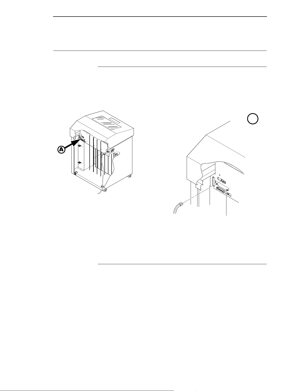
Configuring NIC
Connecting To The Network
To attach the NIC to a network, plug the network cable into the NIC connector
(see Figure 10).
Watch the LEDs in the rear of the printer as they cycle through the power on
self-test. When the test is complete, the STAT led will flash.
A
Connecting To The Network
A
Network Connector
Figure 10. Physical Setup
Configuration Setup
There are two parts to a NIC setup:
1. Configuring the NIC so it can be seen on the network. This involves
network related settings (e.g., an IP address within TCP/IP environments)
configured through the built-in command shell, npsh, or from the control
panel.
2. Configuring a host with a new printer so it knows how to send data to the
NIC. Just being able to see the printer on the network does not mean you
can automatically print to it. A host has to be told where to send the data.
67
Page 68

Chapter 3 Configuring NIC
Note Some network environments do not require any network settings to be
configured on the NIC. However, all network setups require configuration
on the host end.
Configuration Using The Printer Control Panel
NIC settings can be set from the printer control panel. The procedure is
described below.
Note When the printer is first powered on, the messages “Waiting for the
Ethernet Adapter” and “Ethernet Detected” will display on the LCD. After
several other boot messages appear, the LCD will display the message
“E-NET INIT.” This initialization process will take about two minutes.
During that time, you will not be able to change any printer settings from
the control panel. If you attempt to do so, the message “Please Wait
E-NET INIT.” will appear. When the initialization is complete, the message
“E-NET READY” will display, and you may then change any NIC or other
printer configuration options from the control panel.
You can set any of three listed parameters from the printer control panel.
These parameters are located in the ETHERNET PARAMS menu. The
available parameters are:
• IP Address
• Gateway Address
• Subnet Mask
The procedure for changing any of the parameters is the same. The
procedure for changing the IP Address is given here as an example. Use the
same procedure for the other required parameters.
To change the IP Address parameter:
1. Make sure the printer is on and raise the printer cover.
2. Press the ON LINE key to place the printer in the OFFLINE mode.
3. Unlock the ENTER key. (For instructions, refer to “Locking And Unlocking
The ENTER Key” on page 48.)
4. Press the LEFT or RIGHT arrow key until the LCD displays “ETHERNET
PARAMS.”
5. Press the DOWN arrow key to access the “IP Address” parameter.
6. Press the DOWN arrow key to view the current IP Ad dress.
7. Press the DOWN arrow key to access the portion of the IP Address to be
changed.
68
8. Press the LEFT or RIGHT arrow key to select the portion of the IP
Address to be changed.
Page 69

Configuration Alternatives
9. Press the DOWN arrow key.
10. Press the LEFT or RIGHT arrow key to select the desired value.
11. Press the ENTER key to make the selection. An asterisk appears to the
right of the value.
12. Press the UP arrow key and you will be returned to step 8. When you are
finished changing parameters, exit the configuration menus and lock the
ENTER key. (For instructions, refer to “Locking And Unlocking The
ENTER Key” on page 48.)
Caution When a change is made from the control panel, the NIC is re-
initialized. The messages “E-NET RESET” and “E-NET INIT” display
on the control panel. This process takes several minutes. Make sure
not to shut the printer off or ma ke further cha nges to the NIC settings
during this initialization period to prevent a loss of NIC configur ation
information. When the initialization is complete, the message
“E-NET READY” will display.
Configuration Alternatives
Besides the HTML forms and software provided, the NIC internal command
shell, npsh, can also be reached using the following methods.
The Pr in tro n ix P rin te r M an a ge r (P P M)
The PPM utility is a versatile and dynamic program. It allows you to remotely
organize all the printers in your office in a single database; download software
and printer settings from a host computer with a single mouse click; and use a
virtual operator's panel to configure printers in the same room or on the other
side of the world.
Telnet
A TCP/IP command that helps configure NIC settings remotely. A TCP/IP
host starts a Telnet session with the print server and logs in to the device
command shell to alter and view settings.
Example:
telnet 192.75.11.9
69
Page 70

Chapter 3 Configuring NIC
Remote Shell
A TCP/IP command that helps configure print server settings remotely. A
TCP/IP host uses this command to remotely execute a single command on
the NIC.
Example:
rsh spike list prn
This command remotely executes the npsh command list prn on the NIC
named
spike
.
Configuration Using a W eb Brow ser
NIC settings can be configured over TCP/IP through a standard Web browser.
The NIC Web pages provide a handy way to access some of the commands
built into the print server. You can access online help for all HTML pages.
Note If a router is used, make sure a gateway value is configured.
To access the NIC home page:
1. Make sure the print server has an IP address and subnet mask so it is
recognizable on your TCP/IP network.
2. Make sure your network station can successfully
network.
3. Direct your Web browser to the Uniform Resource Locator (URL)
ping the NIC over the
http://IPaddress (e.g., http://192.75.11.9). You will be
able to determine the exact state of the printer from the printer status
screen, as the shown in Figure 11.
70
Page 71

Configuration Alternatives
Figure 11. WWW Printer Status Screen
71
Page 72

Chapter 3 Configuring NIC
72
Page 73

4 The Configuration Menus
Overview
Once you have familiarized yourself with the configuration process using the
tutorial information in Chapter 3, you are ready to complete your configuration
of the printer.
This chapter provides descriptions for each parameter provided by the
configuration menus. Figure 12 shows the configuration main menu and its
first level parameters. The remainder of this chapter includes illustrations of
many additional submenus and parameters nested beneath each of the main
menu options.
73
Page 74

Chapter 4 Configuration Main Menu
Configuration Main Menu
OFFLINE
CONFIG.
CONTROL
(see page 77)
Load Config.
0* - 8
Save Config.
1* - 8
Print Config.
Current*
Factory
Power-Up
All
1 - 8
Delete Config.
1* - 8
Power-Up Config.
0* - 8
Protect Configs.
Disable*
Enable
ACTIVE
EMULATION
(see page 79)
PCL-II*
LP PLUS
IGP/PGL & LP+
IGP/VGL (CODE-V) & LP+
1
EMULATION
(see page 80)
PCL-II*
LP PLUS
IGP/PGL & LP+
IGP/VGL (CODE-V) & LP+
MAINT/MISC
(see page 114)
Hex Dump Mode
Disable*
Enable
Power-up State
Online*
Offline
Display Language
English*
Italian
French
German
Spanish
Power Stacker
Enable*
Disable
2
Continued on
the next page
NOTES:
1
Choices available are limited to the emulations
configured with the printer.
2
Appears only if the power stacker option is installed.
Figure 12. Configuration Main Menu
74
To view options, press:
Down
Up
Next
Prev
To select an option, press ENTER.
To return to main menu, press
CLEAR.
To exit menu, press ON LINE.
* = Default Setting
Page 75

Bi-Tronics*
Prime Signal
Disable*
Enable
TOF Action
Reset*
Do Nothing
Buffer Size in K
1* (1-16)
Centronics
Data Bit 8
Enable*
Disable
PI Ignored
Enable*
Disable
Data Polarity
Standard*
Inverted
Resp. Polarity
Standard*
Inverted
Busy on Strobe
Enable*
Disable
Latch Data On
Leading*
Trailing
Prime Signal
Disable*
Enable
TOF Action
Reset*
Do Nothing
Buffer Size in K
1* (1-16)
Serial
Interface Type
RS-232*
RS-422
Data Protocol
XON / XOFF*
ETX / ACK
ACK / NAK
DTR
Baud Rate
9600*
19200
38400
600
1200
2400
4800
Word Length
8*
7
HOST
INTERFACE
(see page 115)
Serial (cont.)
Stop Bits
Parity
Data Term Ready
Request to Send
Buffer Size in K
Ethernet
Buffer Size in K
Auto Switching
Parallel Hotport
Serial Hotport
1*
2
None*
Odd
Even
Mark
Sense
True*
On-Line and BNF
Off-Line or BF
False
On-Line and BNF*
Off-Line or BF
False
True
1* (1-16)
16* (1-16)
Port Type
Bi-Tronics*
Centronics
Ethernet
Disable
Trickle Time
1/4*
(1/4-16 sec.)
Off
Timeout
10 sec.*
(1-60 sec.)
Report Status
Disable*
Enable
Port Type
RS-232*
RS-422
Disable
Trickle Time
1/4*
(1/4-16 sec.)
Off
Timeout
10 sec.*
(1-60 sec.)
Report Status
Disable*
Enable
ETHERNET
PARAMS
(see page 125)
IP Address
xxx.xxx.xxx.xxx
Gateway Address
xxx.xxx.xxx.xxx
Subnet Mask
xxx.xxx.xxx.xxx
MAC Address
hhhhhhhhhhhh
Novell Protocol
Enable*
Disable
NetBIOS Protocol
Enable*
Disable
Novell Frame
Ethernet 802.2*
802.2 Snap
Auto Sensing
Ethernet II
Ethernet 802.3
PPM Port Number
3001*
(0-65535)
PPM Port Timeout
32 Seconds*
(1-255)
Ethernet Speed
Auto Select*
10 Half Duplex
10 Full Duplex
100 Half Duplex
100 Full Duplex
PRINTER
CONTROL
(see page 127)
Unidirectional
Disable*
Enable
PMD Fault
Enable*
Disable
Open Platen @BOF
Disable*
Enable
Slow Paper Slew
Disable*
Enable
Power Saver Time
15 min.*
(5 sec.-60 min.)
Disable
Instant
DIAGNOSTICS
(see page 129)
Printer Tests
Shift Recycle*
All E’s
E’s + TOF
All H’s
All Underlines
All Black
Shuttle Slow
Shuttle Fast
Shuttle Only
Phase Printer
217* (500 lpm)
123* (1000 lpm)
62* (1500 lpm)
(1 to 2000)
Paperout Adj.
Burnin Test
Print Error Log
Clear Error Log
E-Net Test Page
Test Width
Full Width*
80 col.
Paper Out Dots
40 dots*
(4-76 dots)
System Memory
x Megabytes
Print Statistics
On:
x.x Hrs.
Print:
x.x Hrs.
Print Strokes
Print Lines
11 inch Pages
To view options, press:
Down
Up
Next
Prev
To select an option, press ENTER.
To return to main menu, press
CLEAR.
To exit menu, press ON LINE.
* = Default Setting
RIBBON
MINDER
(see page 132)
New Ribbon
Ribbon Action
Disable*
Display
Fault
Ribbon Size
60 yards*
(1-255)
Ribbon Adjust
0%*
(-99% to 99%)
Fault Action
New Ribbon*
Do Nothing
Figure 12. Configuration Main Menu (continued)
75
Page 76

Chapter 4 Configuration Main Menu
The first-level configuration menu options are briefly described below:
• CONFIG. CONTROL. Allows you to save, print, load, and delete entire
sets of configuration parameters. These options are described briefly in
this chapter and covered in detail in Chapter 3.
• ACTIVE EMULATION. Allows you to select either Hewlett-Packard's
Printer Control Language (PCL-II) or LP Plus.
• If you select PCL-II, you can select the optional IGP
IGP/VGL (Code V) emulations, if installed.
• If you select LP Plus, you can select Epson FX, Proprinter XL, or
P-Series.
• EMULATION. If PCL-II is the active emulation, PCL-II will display and you
can select its parameters for configuration.
• If the optional IGP/PGL or Code V emulations are installed, you can
access their configuration parameters.
• If LP Plus is the active emulation, Epson FX, Proprinter XL, and
P-Series configuration parameters are available.
®
/PGL® or
• MAINT / MISC. Provides miscellaneous functions, such as printing a hex
dump, selecting a display language, and choosing whether the printer will
power up offline or online.
• HOST INTERFACE. Allows you to select the printer interface depending
on what type of interface cabling you installed while setting up your
printer. In addition to selecting an active interface, this menu also allows
you to configure several parameters for each interface.
• ETHERNET PARAMS. Allows you to view and change the IP Address,
Gateway Address, and Subnet Mask. The MAC Address may also be
viewed. In addition, Novell and Printer Manager options can be set.
• PRINTER CONTROL. Allows you to sele ct seve ra l op erat i ng pa ram ete rs
for the printer, such as the speed at which paper will advance when FF
(Form Feed) is pressed.
• DIAGNOSTICS. Includes the printer's diagnostic tests, system memory,
and print statistics.
• RIBBONMINDER. Allows you to enable the RibbonMinder
set its parameters.
™
feature and
76
Page 77

Config. Control Menu
CONFIG.
CONTROL
Load Config.
0*
1
2
3
4
5
6
7
8
Save Config. Print Config.
1*
2
3
4
5
6
7
8
Current*
Factory
Power-up
All
1
2
3
4
5
6
7
8
Delete Config.
1*
2
3
4
5
6
7
8
Power-up
Config.
0*
1
2
3
4
5
6
7
8
Disable*
Enable
To view options, press:
Down
Up
Next
Prev
To select an option, press ENTER.
To return to main menu, press
CLEAR.
To exit menu, press ON LINE.
Protect
Configs.
* = Default Setting
The CONFIG. CONTROL menu manages configurations, which are
groupings of parameter values that can be stored in printer memory. Brief
descriptions follow for each option.
Load Config.
The printer can store up to eight unique configurations in memory. This
parameter allows you to select and load a specific configuration.
Configuration 0 is the factory default, and its parameters cannot be changed.
It is always available for loading. See page 60 for a detailed description and
sample procedure.
77
Page 78

Chapter 4 Config. Control Menu
Save Config.
This option allows you to save up to eight unique configurations to meet
different print job requirements, which eliminates the need to change the
parameter settings for each new job.
The configurations are stored in memory. They will not be lost if you turn off
the printer. Configuration 0 is a factory-preset configuration, which cannot be
changed or saved. See page 56 for a detailed description and sample
procedure.
Note If the Protect Configs. parameter is enabled, the new configuration will not
be saved unless the existing configuration has been deleted.
Print Config.
Allows you to print a listing of stored printer configurations. It is recommended
you store the configurations in a safe place for quick referral, such as inside
the printer, if you have a cabinet model. See page 58 for a detailed
description and sample procedure.
Delete Config.
Allows you to delete one or all of your eight customized configurations.
Configuration 0 is a factory-preset configuration and cannot be changed or
deleted.
Power-Up Config.
Allows you to specify which of the nine configurations (0-8) will be the powerup configuration. The factory default for power-up is configuration 0. See page
62 for a detailed description and sample procedure.
Protect Configs.
Allows you to specify whether or not a new configuration should overwrite an
existing configuration when you activate the Save Config. parameter.
• Disable. The default. The new configuration will overwrite the existing
configuration.
• Enable. The new configuration will not overwrite the existing
configuration, and the message “CONFIG. EXISTS / Delete First”
displays. You must delete the existing configuration (1-8) before trying to
save the new configuration.
78
Page 79

Active Emula tion Menu
ACTIVE
EMULATION
PCL-II*
LP PLUS
IGP/PGL &
1
LP+
IGP/VGL
(CODE-V) &
1
LP+
The ACTIVE EMULATION menu determines what emulations are available.
• PCL-II. The default. The PCL-II emulation is active.
• LP PLUS. Allows you to select LinePrinter Plus as the active emulation. If
LP PLUS is the active emulation, you can select Epson, Proprinter III XL,
or P-Series as the printer protocol (see page 86).
• IGP/PGL & LP+ and IGP/VGL (Code V) & LP+. The ACTIVE
EMULATION function also allows you to activate either the PGL or the
Code V emul ation. There are two methods for sel ecting the desired
emulation. The first is by selecting the emulation directly from the printer
menu. The second is by sending a host command which will switch the
emulation automatically. See the appropriate Technical Reference
Manual for more information on these command codes.
When changing from one IGP emulation to the other, the printer will load
the power-up configuration. Thus, any setting performed before selecting
those emulations and not saved in flash memory will be lost.
For more information on IGP/PGL and Code V, see the appropriate
Technical Reference Manual.
Note To configure an IGP emulation, the IGP emulation must be selected in the
ACTIVE EMULATION menu. The IGP emulation that is not selected will
not appear in the EMULATION menu.
79
Page 80

Chapter 4 Emulation Menu
Emulation Menu
EMULATION
PCL-II*
(see page 81)
LP PLUS
(see page 86) (see page 102) (see page 107)
IGP/PGL &
1
LP+
IGP/VGL
(CODE-V) &
1
LP+
To view options, press:
Down
Up
Next
Prev
To select an option, press ENTER.
To return to main menu, press
CLEAR.
To exit menu, press ON LINE.
* = Default Setting
1
= If installed
The EMULATION menu is the gateway to configure the emulations available
with the P5000LJ printer. The control codes for each of these emulations are
described in their respective Technical Reference Manuals.
80
PCL-II Emulation
Hewlett-Packard's Printer Control Language that is compatible with HewlettPackard systems.
LP Plus Emulations
• Epson FX. This LP Plus emulation is provided for compatibility with the
Epson FX-1050 printer control language.
• Proprinter XL. This LP Plus emulation is provided for compatibility with
the IBM Proprinter III XL printer control language.
• P-Series. This is the Printronix P-Series printer control language,
provided as part of LP Plus.
Optional Emulations
IGP/VGL (Code V) and IGP/PGL are optional graphics emulations. They can
be selected and configured only if you have purchased these options. PCL-II
must be the active emulation for Code V or IGP/PGL to operate.
Page 81

EMULATION
(from page 80)
PCL-II
PCL-II Emulation
PCL-II Emulation
* = Factory Default
Primary
Char. Set
ID
0* - 109, xx
Symbol Set
(see next page)
Pitch
10*, 12, 13.3
15, 16.67, 20
Density
Data Processing*
NLQ
OCR-A
OCR-B
High Speed
Graphics
Density
60 dpi*
70 dpi
Secondary
Char. Set
ID
0* - 109, xx
Symbol Set
(see next page)
Pitch
10*, 12, 13.3
15, 16.67, 20
Density
Data Processing*
NLQ
OCR-A
OCR-B
High Speed
Perforation
Skip
Disable*
Enable
Display
Functns
Disable*
Enable
Page Length
Rep.
Inches/Page*
Lines/Page
LF After CR
CR After LF
CR After FF
CR After VT
Line
Terminator
Disable*
Enable
Disable*
Enable
Disable*
Enable
Enable*
Disable
Max. Line
Width
13.2 inches*
13.6 inches
PTX Linefeed
Disable*
Enable
Face, CPI
Delay
Enable*
Disable
LPI Adjust
6 lpi*
8 lpi
Page L. /
Lines
66*
(1-128)
Page L. /
Inches
11.0 inches*
(2-16 inches)
Config. Print
Symbol Set
Print
Reset Cmd
CFG Ld
Power-up Config*
Current Config
Factory Config
Disable
81
Page 82

Chapter 4 Emulation Menu
Primary
Char. set
(from previous
page)
Symbol Set
Roman-8[8U]*
Turkish-8[8T]
Arab-8[8V]
Cyrillic[8R]
PC858 MtLi[13U]
MC Text[12J]
Roman-9[4U]
Latin-9[9N]
Win3.0Lat-1[9U]
Japan Postnet
Katakana Post
ASCII[0U]
Math Sym[0A/0M ]
LineDraw[0B/0L]
IS0 Den/Nor[0D]
Roman Ext.[0E]
IS0 UK[1E]
IS0 France[0F]
IS0 German[0G]
Hebrew[0H]
Japan ASCII[0K]
Katakana[1K]
Block Char[1L]
OCR-A[0O]
OCR-B[1O]
ISO Swe/Fin[0S]
ISO Spain[1S]
ISO Italian[0I]
ISO Portugu[4S]
Latin-1[0N]
Latin-2[2N]
Latin-5[5N]
Latin-6[6N]
Baltic[19L]
PC8 DanNor[11U]
PC8 Cd437[10U]
PC850 MtLi[12U]
PC851 LtGk[12G]
PC852 Lat2[17U]
PC Turkish[9T]
PC Hebrew[15H]
PC Lat/Ara[10V]
PC Cyrillic[3R]
Win3.1Lat1[19U]
Win3.1Lat-2[9E]
Win3.1Lat-5[5T]
Math-8[8M]
PS Math[5M]
Greek-7[12N]
Postnet4[15Y]
Postnet11.25
Greek-8[8G]
Hebrew-8[8H]
Katakana-8[8K]
DEC 256 Greek
ELOT 928 Greek
Greek 3
ABY Greek
ABG Greek
ELOT 927 Greek
Greek 437
Greek 8859-7
Secondary
Char. Set
(from previous
page)
Symbol Set
(identical to Primary
Character Set)
Primary Char . Set
You can select one of 92 pre-defined character sets by ID (although character
sets range from 0 - 109, not all sets are available on the LJ500 printer), or you
can select pitch, symbol set, and typeface individually. If the combination you
choose matches one of the 92 predefined sets, the ID submenu will reflect
that selection. If not, the ID menu will display
xx to indicate that the current
character set does not match a pre-defined set. Set 0 is the default, and its
attributes are 10 cpi, Data Processing typeface, and Roman 8 symbol set.
Secondary Char. Set
Your printer can store an additional character set. To toggle between them,
send the Shift In (Decimal 15, to select the Primary character set) or Shift Out
(Decimal 14, to select the Secondary character set).
82
Page 83

PCL-II Emulation
Page Length Rep.
• Inches/Page. All page length calculations are based on the inches
displayed on the panel.
• Lines/Page. All changes in LPI or density will be changed accordingly.
The length of the page is the number of lines per inch, or lpi.
For example, if the form in use is 82 lines at 6 lpi, the page is physically
13.67 inches. Since 13.67 inches is not selectable from the Length in
Inches menu, change the representation to lines, then set the number of
lines to 82. The inches menu will display 13.6 inches although the printer
internally keeps the exact form length of 13.67 inches.
Max. Line Width
Set the maximum line width at 13.2 inches (the default) or 13.6 inches.
Face, CPI Delay
Allows the combination of different font densities on the same line.
• Enable. Different font densities can be used on the same line.
• Disable. Only the same font densities are allowed on the same line.
Graphics Density
Graphics can be printed in 60 DPI (the default) or 70 DPI.
Perforation Skip
• Disable. Allows printing on page perforation.
• Enable. You may set up a skip-over margin. For example, a skip-over
margin of one inch creates a one inch margin at the bottom of the page.
Display Functns
• Disable. The default. Control characters are not printed.
• Enable. Control characters are printed before they get executed. This is a
useful debugging tool.
Line Terminator
You can specify what will be used to indicate the end of a line. Four options
are available: LF after CR, CR after LF, CR after FF, and CR after VT. Each of
these options may be enabled or disabled independent of one another.
83
Page 84

Chapter 4 Emulation Menu
PTX Linefeed
• Disable. The default. Linefeed is to be performed as calculated from the
bottom of the graphics or barcode, thereby disrupting the vertical text
alignment.
• Enable. The Linefeed moves to the next line as calculated from the Top
of Form position, thereby retaining vertical text alignment. When printing
graphics or bar codes, you may want to set the PTX Linefeed parameter
to Enable to maintain text alignment.
PTX Linefeed Enabled PTX Linefeed Disabled
LINE 1
LINE 2
LINE 3
Linefeed
LINE 1
LINE 2
Linefeed
LINE 3
LPI Adjust
This parameter lets you specify the lines per inch (lpi) values: 6 LPI (the
default) or 8 LPI.
Page L. /Lines
This parameter lets you set physical page length in lines from 12 to 96 at 6 lpi,
or 16 to 128 at 8 cpi. The default is 66 lines at 6 lpi.
Note If 6 lpi is selected, you will be able to scroll the menu to 128 (an invalid
length). However, when you press ENTER to select this value, the menu
will return with the maximum lines for 6 lpi (i.e., 96 lines). Similarly,
selecting too few lines for 8 lpi will cause the menu to return with 16 lines.
84
Page L. /Inches
This parameter allows you to set physical page length from 2 to 16 inches, in
increments of half an inch. The default is 11 inches.
Config. Print
This option prints the emulation's parameters and the currently selected
values.
Page 85

PCL-II Emulation
Symbol Set Print
This option prints a list of all the available sets. The character set number
prints to the left of the character set sample.
Reset Cmd CFG Ld
When the printer receives a host data stream reset command in addition to
resetting printer variables, the selected configuration will be loaded.
• Disable.
The printer ignores the reset command when it is received and continues
to use the currently loaded configuration.
• Power-Up Config.
The power-up configuration is loaded when the reset command is
received.
• Current Config.
If you have preset and presaved multiple configurations, then the
currently selected presaved configuration is loaded when the reset
command is received.
• Factory Config.
The factory installed configuration is loaded when the reset command is
received.
85
Page 86

Chapter 4 Emulation Menu
LP Plus Emulation
EMULATION
(from page 80)
LP PLUS
Printer
Protocol
P-Series* Proprinter XL Epson FX
Print Char.
Set
CPI/LPI
Select
Select CPI
10.0 CPI*
12.0 CPI
15.0 CPI
17.1 CPI
20.0 CPI
Select LPI
6.0 LPI*
8.0 LPI
10.3 LPI
Font
Attributes
Typeface
Data Processing*
NLQ
OCR-A
OCR-B
High Speed
NLQ Sans Serif
Prop. Spacing
Disable*
Enable
Bold Print
Disable*
Enable
Italic Print
Disable*
Forward Slant
Backward Slant
Slashed Zero
Disable*
Enable
Serial Matrix
Page
Format
Form Length Form Width
Abs. Length IN
11.0* inches
(0.1-24)
Abs. Length MM
279.4* mm.
(0.1-609.6)
Funct. of Lines
66* lines
(1-192)
P-Series XQ
Reset Cmd
CFG Ld
Disable*
Power-up config
Current config
Factory config
Abs. Width IN
13.6* inches
(0.1-13.6)
Abs. Width MM
345.4* mm.
(0.1-345.4)
Function of CPI
136* characters
(1-272)
Margins
Left Margin
0* columns
(0-369)
Right Margin
0* columns
(0-369)
Bottom Margin
0* lines
(0-451)
Perforation
Skip
Disable*
1/2 inch
2/3 inch
5/6 inch
1 inch
(see page 90) (see page 93)
86
(see page 95)
(see page 97)
(see page 100)
To view options, press:
Down
Up
Next
Prev
To select an option, press ENTER.
To return to main menu, press
CLEAR.
To exit menu, press ON LINE.
* = Default Setting
Page 87

LP Plus Emulation
Printer Protocol
Select the LinePrinter+ protocol you wish to use. Refer to the PCL-II/
LinePrinter Plus Technical Reference Manual for more information.
Print Char. Set
When this selection is displayed and the ENTER key is pressed, the current
character set is printed.
CPI/LPI Select
This parameter lets you specify the characters per inch (cpi) value and lines
per inch (lpi) value.
Font Attributes
Typefaces
• Data Processing. A general purpose font printing out at 120 dpi
horizontally and 72 dpi vertically. The width of the font will vary with each
cpi.
• NLQ. A high quality font printing at 180 dpi horizontally and 96 dpi
vertically. This font has serifs, and the width of the font varies with the cpi.
• OCR-A / OCR-B. Optical character recognition fonts printing at 120 dpi
horizontally and 144 dpi vertically. Both fonts print only at 10 cpi.
• High Speed. A draft quality font printing at 120 dpi horizontally and 48 dpi
vertically. The width of the font varies with the cpi.
• NLQ Sans Serif. A high quality font printing at 180 dpi horizontally and 96
dpi vertically. This font prints without serifs. The width of the font varies
with the cpi.
Prop. Spacing
Each printed character is contained inside a character cell. The width of the
character cell includes the character and the space around the character.
• Disable. Each character cell is printed with the same width. Each column
in the printed text will line up.
• Enable. The width of each character cell varies with the width of the
character. For example, [i] takes less space to print than [m]. Using
proportional fonts generally increases the readability of printed
documents, giving text a typeset appearance.
87
Page 88

Chapter 4 Emulation Menu
Bold Print
• Disable. Text is printed normally.
• Enable. Te xt is printed with a heavy line thickness.
Italic Print
• Disable. Text is printed normally.
• Forward Slant. Text is printed with a forward slant.
• Backward Slant. Text is printed with a backward slant.
Slashed Zero
This parameter allows you to print the numeral “0” with or without the slash.
This option applies to all character sets except OCR-A and OCR-B.
• Disable. Zero is printed without a slash.
• Enable. Zero is printed with a slash.
Page Format
Forms Length
Forms length is the number of lines that can be printed on a page. Y ou can set
forms length in inches, millimeters (mm) or as a function of the current LPI
(lines per inch).
Forms Width
The forms width can be specified in inches, millimeters, or as a function of the
current CPI (characters per inch). The forms width set should not exceed the
actual paper width.
Margins
•
Right Margin. Set in columns. Column zero is defined as the far right
edge of the page, and column numbering increments from right to left.
• Left Margin. Set in columns. Column zero is defined as the far left edge
of the page, and column numbering increments from left to right.
• Bottom Margin. Defined in lines, starting from line zero at the bottom of
the page and incrementing from the bottom up.
88
Perforation Skip
•
Disable. Allows printing on page perforation.
• You may set up a skip-over margin of 1/2 inch, 2/3 inch, 5/6 inch, or 1
inch. For example, a skip-over margin of 1 inch allows a 1 inch margin at
the bottom of the page.
Page 89

LP Plus Emulation
Reset Cmd CFG Ld
When the printer receives a host data stream reset command in addition to
resetting printer variables, the selected configuration will be loaded.
• Disable.
The printer ignores the reset command when it is received and continues
to use the currently loaded configuration.
• Power-Up Config.
The power-up configuration is loaded when the reset command is
received.
• Current Config.
If you have preset and presaved multiple configurations, then the
currently selected presaved configuration is loaded when the reset
command is received.
• Factory Config.
The factory installed configuration is loaded when the reset command is
received.
89
Page 90

Chapter 4 Emulation Menu
P-Series Emulation
Character Set
(from above)
IBM PC*
Printer
Protocol
(from page 86)
P-Series
Control Code
06
8.0 LPI*
10.3 LPI
6.0 LPI
Select SFCC
1*
(0-7F hex)
Multinational ECMA Latin 1
Control Code 08Define CR
Elongated*
Backspace
EVFU Select
Enable*
Disable
Code
CR = CR*
CR = CR + LF
Alt. Set 80-9F Character
Control Code*
Printable
DEC Mult.
OCR-A
* = Factory Default
Auto LF
Disable*
Enable
Set
(see below) Even dot plot*
Overstrike Define LF
Enable*
Disable
SFCC d
Command
Double high
OCR-B
Code
LF = CR + LF*
LF = LF
Primary Subset
ASCII (USA)*
French
German
English
Danish
Swedish
Italian
Spanish
Japanese
French Canadian
Latin American
Danish II
Spanish II
Latin Am II
Extended Subset
Code Page 437*
Code Page 850
ASCII (USA)*
EBCDIC
Primary Subset
ASCII (USA)*
German
Swedish
Danish
Norwegian
Finnish
English
Dutch
French
Spanish
Italian
Turkish
Japanese
Extended Subset
Multinational*
Barcode 10 CPI
Mult. DP 10 CPI
Mult. DP 12 CPI
Mult. LQ 10 CPI
Greek DP 10 CPI
Greek DP 12 CPI
Greek LQ 10 CPI
Grap. DP 10 CPI
Grap. LQ 10 CPI
Sci. DP 10 CPI
Sci. DP 12 CPI
Sci. LQ 10 CPI
ASCII (USA)*
French
German
English
Norw./Danish
Swedish
Italian
Spanish
Japanese
French Canadian
Dutch
Finnish
Swiss
Latin 2 8859-2
Polish POL1
ABY Greek
Greek 8859-7
Latin 2 852 Bulgarian
DEC 256
Greek
ABG Greek ELOT 927
PC851
LtGk[12G]
ELOT 928
Greek
Greek
Greek-7[12N]
Latin-9
8859-15
Greek 3
Greek 437
Greek-8[8G]
90
Page 91

P-Series Emulation
Control Code 06
Control Code 06 defines the function of ASCII code hex 06 (ACK). You can
select an alternate line spacing of 6, 8, or 10.3 LPI.
Control Code 08
Control Code 08 defines the function of ASCII code hex 08 (BS). You can
define the code to output an elongated character or a backspace.
Define CR Code
This option controls the action of the printer when it receives a Carriage
Return code (hex 0D) from the host computer. If this feature is enabled, each
time the printer receives a Carriage Return, it inserts an additional Line Feed
code (hex 0A) into the data stream. Do not use this feature if the host
computer sends Line Feeds to the printer.
• CR = CR. Does not insert an extra Line Feed after each Carriage Return.
• CR = CR + LF. Inserts an extra Line Feed after each Carriage Return.
The next print position will be print position 1 of the next line.
Auto LF
This option defines the printer action when print data is received past the
forms width setting.
• Disable. Discards any data past the forms width.
• Enable. Performs an automatic carriage return and line feed when data is
received past the forms width.
Overstrike
This option enables you to print bold characters.
• Enable. Turns on bold print. When enabled, overstrike printing slows
down the printer.
• Disable. Turns off bold print.
Define LF Code
• LF = CR + LF. Forces an automatic carriage return with each line feed
command. The next print position is print position 1 of the next line.
• LF = LF. Does not perform an automatic carriage return. The next print
position will be the current print position of the next line.
91
Page 92

Chapter 4 Emulation Menu
Select SFCC
This parameter allows you to select which ASCII codes will function as the
Special Function Control Code (SFCC) command delimiter. P-Series codes
can use hex 00 through hex 7F. Options include the following:
• ESC (hex 1B)
• SOH (hex 01)
• ETX (hex 03)
• CIRCUMFLEX (hex 5E)—also called caret (^)
• TILDE (hex 7E)—(~)
Note SOH, ETX and ESC are non-printables. The characters (^) and (~) are
printable. However, do not use them as printables in the host data stream if
either is chosen as a delimiter, because print errors will occur.
EVFU Select
Controls how the printer handles vertical formatting.
• Enable. Enables the VFU and selects P-Series compatible Electronic
Vert ical Format Unit (EVFU).
• Disable. Disables VFU processing.
Alt. Set 80-9F
Determines whether the printer processes ASCII codes hex 80 through hex
9F as control codes or as printable characters.
Character Set
Specifies a character set as shown in the character set menu. To use one of
these sets, choose the desired group heading (such as Multinational) and
press ENTER. Then choose the desired set within that group (such as
EBCDIC) and press ENTER. Both the group and the desired set name will
include an asterisk to indicate your selection.
SFCC d Command
• Even dot plot. This option interprets SFCC d Command as even dot plot.
• Double high. This option interprets SFCC d Command as double high.
Select this option for backward compatibility.
92
Page 93

Printer
Protocol
(from page 86)
Proprint e r XL
Proprinter XL Emulation
Proprinter XL Emulation
* = Factory Default
Define CR
Code
CR = CR*
CR = CR + LF
Auto LF Define LF
Enable*
Disable
LF = LF*
LF = CR + LF
Code
FF valid at
TOF
Enable*
Disable
Character
Set
Code Page 437*
Code Page 850
OCR-A
OCR-B
Latin 2 8859-2
Latin 2 852
Bulgarian
Latin-9 8859-15
Polish POL1
Multinational
ASCII (USA)*
EBCDIC
DEC 256 Greek
ELOT 928 Greek
Greek 3
ABY Greek
ABG Greek
ELOT 927 Greek
Greek 437
Greek 8859-7
PC851 LtGk[12G]
Greek-7[12N]
Greek-8[8G]
Alt. Char Set 20 CPI
Condensed
Set 1*
Set 2
Enable*
Disable
Define CR Code
This option controls the action of the printer when it receives a Carriage
Return code (hex 0D) from the host computer. If this feature is enabled, each
time the printer receives a Carriage Return, it inserts an additional Line Feed
code (hex 0A) into the data stream. Do not use this feature if the host
computer sends Line Feeds to the printer.
• CR = CR. Does not insert an extra Line Feed after each Carriage Return.
• CR = CR + LF. Inserts an extra Line Feed after each Carriage Return.
93
Page 94

Chapter 4 Emulation Menu
Auto LF
This option defines the printer actions when print data is received past the
forms width setting.
• Enable. Performs an automatic carriage return and line feed when data is
received past the forms width.
• Disable. Discards any data past the forms width.
Define LF Code
• LF = LF. Does not perform an automatic carriage return when a line feed
command is received. The next print position will be the current print
position of the next line.
• LF = CR + LF. Forces an automatic carriage return with each line feed
command received. The next print position is print position 1 of the next
line.
FF V alid at TOF
• Enable. Performs a form feed when the host sends a Form Feed
command and the printer is at the top of form.
• Disable. Will not perform a form feed when the host sends a Form Feed
command and the printer is at the top of form.
Character Set
Specifies a character set as shown in the menu. To use one of these sets,
choose the desired character set and press ENTER. The desired set will be
marked with an asterisk to indicate your selection.
Alt. Char Set
This option determines if data in the range of hex 80 through hex 9F should
be interpreted as a control code or as a printable character.
• Set 1. Interprets data in the range of hex 80 through hex 9F as a control
code.
• Set 2. Prints data for the characters at hex locations 03, 04, 05, 06, 15,
and 80 through 9F.
20 CPI Condensed
Condensed print characters are narrower than the normal character set. This
is helpful for applications for which you need to print the maximum amount of
information on a page.
94
• Enable. Prints characters about 60 percent the width of normal
characters when condensed print is chosen by the host computer.
• Disable. Does not condense print widths, even if condensed print is
chosen by the host.
Page 95

Printer
Protocol
(from page 86)
Epson FX
Epson FX Emulation
Epson FX Emulation
* = Factory Default
Define CR
Code
CR = CR*
CR = CR + LF
Auto LF Define LF
Enable*
Disable
LF = LF*
LF = CR + LF
Code
Printer Select
Disable*
Enable
Character
Set
Epson Set*
ASCII (USA)*
French
German
English
Danish I
Swedish
Italian
Spanish I
Japanese
Norwegian
Danish II
Spanish II
Latin Am I
French Canadian
Latin Am II
OCR-A
OCR-B
Latin 2 8859-2
Latin 2 852
Cyrillic 866
Bulgarian
Latin-9 8859-15
Polish POL1
Multinational
ASCII (USA)*
EBCDIC
DEC 256 Greek
ELOT 928 Greek
Greek 3
ABY Greek
ABG Greek
ELOT 927 Greek
Greek 437
Greek 8859-7
PC851 LtGk[12G]
Greek-7[12N]
Greek-8[8G]
IBM PC
20 CPI
Condensed
Enable*
Disable
Alt. Set 80-9F
Control Code*
Printable
95
Page 96

Chapter 4 Emulation Menu
Define CR Code
The Define CR Code option controls the action of the printer when it receives
a Carriage Return code (hex 0D) from the host computer. If this feature is
enabled, each time the printer receives a Carriage Return, it inserts an
additional Line Feed code (hex 0A) into the data stream. Do not use this
feature if the host computer sends Line Feeds to the printer.
• CR = CR. Does not insert an extra Line Feed after each Carriage Return.
• CR = CR + LF. Inserts an extra Line Feed after each Carriage Return.
Auto LF
This option defines the printer actions when print data is received past the
forms width setting.
• Enable. Performs an automatic carriage return and line feed when data is
received past the forms width.
• Disable. Discards any data past the forms width.
Define LF Code
The Define LF Code option controls the action of the printer when it receives a
Line Feed code (hex 0A) from the host computer. If this feature is enabled,
each time the printer receives a Line Feed, it inserts an additional Carriage
Return code (hex 0D) into the data stream. This feature is required if the host
computer does not send Carriage Returns to the printer.
• LF = LF. Does not add a Carriage Return with a Line Feed.
• LF = CR + LF. Adds an extra Carriage Return with each Line Feed.
Printer Select
• Disable. Ignores the ASCII DC1 and DC3 control codes.
• Enable. Disables the printer when a DC1 control code is received, and
enables the printer when a DC3 control code is received.
Character Set
This parameter selects a character set for the Epson emulation, as shown in
the Character Set menu. Note that when OCR-A or OCR-B is selected as the
print language, the Font Attribute Typeface option under the LinePrinter Plus
menu (page 86) is changed to OCR-A or OCR-B, respectively.
20 CPI Condensed
96
Condensed print characters are narrower than the normal character set. This
is helpful for applications for which you need to print the maximum amount of
information on a page.
• Enable. Prints about 60 percent of the width of normal characters when
condensed print is chosen by the host computer. For example, a 12 CPI
Draft font will condense to 20 CPI.
• Disable. Does not condense print widths, even if condensed print is
chosen by the host.
Page 97

Printer
Protocol
(from page 86)
Serial
Matrix
Serial Matrix Emulation
Alt. Set 80-9F
• Control Code. Interprets data in the range of hex 80 through hex 9F as a
control code.
• Printable. Prints data in the range of hex 80 through hex 9F.
Serial Matrix Emulation
* = Factory Default
Control Code
06
8.0 LPI*
10.3 LPI
6.0 LPI
Alt. Set
80-9F
Control Code*
Printable
Define CR
Code
CR = CR*
CR = CR + LF
Character
Set
(see page 99) Even dot plot*
Auto LF
Enable*
Disable
Esc d
command
Double high
Overstrike
Enable*
Disable
Define LF
Code
LF = LF*
LF = CR + LF
Printer
Select
Disable*
Enable
Control Code 06
Control Code 06 defines the function of ASCII code hex 06 (ACK). You can
select an alternate line spacing of 6, 8, or 10.3 LPI.
Define CR Code
This option controls the action of the printer when it receives a Carriage
Return code (hex 0D) from the host computer. If this feature is enabled, each
time the printer receives a Carriage Return, it inserts an additional Line Feed
code (hex 0A) into the data stream. Do not use this feature if the host
computer sends Line Feeds to the printer.
• CR = CR. Does not insert an extra Line Feed after each Carriage Return.
• CR = CR + LF. Inserts an extra Line Feed after each Carriage Return.
The next print position will be print position 1 of the next line.
97
Page 98

Chapter 4 Emulation Menu
Auto LF
The Auto LF option defines the printer actions when print data is received past
the forms width setting.
• Enable. Performs an automatic carriage return and line feed when data is
received past the forms width.
• Disable. Discards any data past the forms width.
Overstrike
This option enables you to print bold characters.
• Enable. Turns on bold print. When enabled, overstrike printing slows
down the printer.
• Disable. Turns off bold print.
Define LF Code
• LF = LF. Does not perform an automatic carriage return when a line feed
command is received. The next print position will be the current print
position of the next line.
• LF = CR + LF. Forces an automatic carriage return with each line feed
command received. The next print position is print position 1 of the next
line.
Printer Select
• Disable. Ignores the ASCII DC1 and DC3 control codes.
• Enable. Disables the printer when a DC1 control code is received, and
enables the printer when a DC3 control code is received.
Alt. Set 80-9F
• Control Code. Interprets data in the range of hex 80 through hex 9F as a
control code.
• Printable. Prints data in the range of hex 80 through hex 9F.
Character Set
Specifies a character set as shown in the “Serial Matrix Character Set Menu”
on page 99. To use one of these sets, choose the desired group heading
(such as European Sets) and press ENTER. Then choose the desired set
within that group (such as Roman 8) and press ENTER. Both the group and
the desired set name will include an asterisk to indicate your selection.
Character sets are shown in detail in the Character Sets Reference Manual.
98
ESC d Command
• Even dot plot. Interprets the ESC d command as even dot plot.
• Double high. Interprets the ESC d Command as double high. Select this
option for backward compatibility.
Page 99

Character Set
(from page 97)
Serial Matrix Emulation
Serial Matrix Character Set Menu
* = Factory Default
IBM PC*
Primary Subset
ASCII (USA)*
French
German
English
Danish
Swedish
Italian
Spanish
Japanese
French Canadian
Latin American
Danish II
Spanish II
Latin Am II
Extended Subset
Code Page 437*
Code Page 850
Multinational ECMA Latin 1
ASCII (USA)*
EBCDIC
Primary Subset
ASCII (USA)*
German
Swedish
Danish
Norwegian
Finnish
English
Dutch
French
Spanish
Italian
Turkish
Japanese
Extended Subset
Multinational*
Barcode 10 CPI
Mult. DP 10 CPI
Mult. DP 12 CPI
Mult. LQ 10 CPI
Greek DP 10 CPI
Greek DP 12 CPI
Greek LQ 10 CPI
Grap. DP 10 CPI
Grap. LQ 10 CPI
Sci. DP 10 CPI
Sci. DP 12 CPI
Sci. LQ 10 CPI
DEC Mult.
ASCII (USA)*
French
German
English
Norw./Danish
Swedish
Italian
Spanish
Japanese
French Canadian
Dutch
Finnish
Swiss
OCR-A
Latin 2 852
Polish POL1
Greek 3
ELOT 927
Greek
OCR-B
Bulgarian Latin-9
DEC 256
Greek
ABY Greek
Greek 437
Latin 2 8859-2
8859-15
ELOT 928
Greek
ABG Greek
Greek 8859-7
PC851
LtGk[12G]
Greek-7[12N]
Greek-8[8G]
99
Page 100

Chapter 4 Emulation Menu
P-Series XQ Emulation
Printer
Protocol
(from page 86)
P-Series
XQ
Control Code
06
6.0 LPI
8.0 LPI*
10.3 LPI
HS Print
char 02 STX*
char 03 ETX
char 09 HT
* = Factory Default
Define CR
Code
CR = CR*
CR = CR + LF
EVFU Select Upr. Case
Enable*
Disable
Auto LF
Disable*
Enable
Select
Disable*
Enable
Define LF
Code
LF = CR + LF*
LF = LF
Slew
Relative
1 to 16 lines*
1 to 15 lines
Compressed
Print
char 01 SOH*
char 03 ETX
char 09 HT
Elong/Alt.
Font
Elng=BS Font=SO*
Elng=SO Font=BS
Control Code 06
Control Code 06 defines the function of ASCII code hex 06 (ACK). You can
select an alternate line spacing of 6, 8, or 10.3 LPI.
Define CR Code
This option controls the action of the printer when it receives a Carriage
Return code (hex 0D) from the host computer. If this feature is enabled, each
time the printer receives a Carriage Return, it inserts an additional Line Feed
code (hex 0A) into the data stream. Do not use this feature if the host
computer sends Line Feeds to the printer.
• CR = CR. Does not insert an extra Line Feed after each Carriage Return.
• CR = CR + LF. Inserts an extra Line Feed after each Carriage Return.
The next print position will be print position 1 of the next line.
Auto LF
This option defines the printer action when print data is received past the
forms width setting.
• Disable. Discards any data past the forms width.
• Enable. Performs an automatic carriage return and line feed when data is
received past the forms width.
100
 Loading...