

Page 1
®
Maintenance Manual
The Printronix P5000 series of Line Matrix Printers
Page 2

Page 3

The Printronix P5000 series of Line Matrix Printers
Maintenance Manual
164253-001, Rev D
®
Page 4

Trademark Acknowledgements
T rade mark Ack nowledgemen ts
ANSI is a registered trademark of American National Standards Institute, Inc.
Centronics is a registered trademark of Genicom Corporation.
Code V is a trademark of Quality Micro Systems.
Chatillon is a trademark of John Chatillon & Sons, Inc.
Dataproducts is a registered trademark of Dataproducts Corporation.
EIA is a registered service mark of Electronic Industries Association.
ENERGY STAR® is a registered trademark of the United States
Environmental Protection Agency. As an
Printronix has determined that this product meets the
guidelines for energy efficiency.
Ethernet is a trademark of Xerox Corporation.
IBM is a registered trademark of International Business Machines
Corporation.
IEEE is a registered trademark of the Institute of Electrical and Electronics
Engineers.
IGP is a registered trademark of Printronix, Inc.
Intelligent Printer Data Stream and IPDS are trademarks of International
Business Machines Corporation.
LinePrinter Plus is a registered trademark of Printronix, Inc.
MS-DOS is a registered trademark of Microsoft Corporation.
PC-DOS is a trademark of International Business Machines Corporation.
PGL is a registered trademark of Printronix, Inc.
PrintNet is a trademark of Printronix, Inc.
Printronix is a registered trademark of Printronix, Inc.
PSA is a trademark of Printronix, Inc.
QMS is a registered trademark of Quality Micro Systems.
RibbonMinder is a trademark of Printronix, Inc.
SureStak is a trademark of Printronix, Inc.
Torx is a registered trademark of Camcar/Textron Inc.
Utica is a registered trademark of Cooper Power Tools.
ENERGY STAR® Partner,
ENERGY STAR®
War ranty and Copyrig ht Inform ation
Printronix, Inc. makes no representations or warranties of any kind regarding
this material, including, but not limited to, implied warranties of
merchantability and fitness for a particular purpose. Printronix, Inc. shall not
be held responsible for errors contained herein or any omissions from this
material or for any damages, whether direct, indirect, incidental or
consequential, in connection with the furnishing, distribution, performance or
use of this material. The information in this manual is subject to change
without notice.
This document contains proprietary information protected by copyright. No
part of this document may be reproduced, copied, translated or incorporated
in any other material in any form or by any means, whether manual, graphic,
electronic, mechanical or otherwise, without the prior written consent of
Printronix, Inc.
All rights reserved.
COPYRIGHT © 1996, 1999, PRINTRONIX, INC.
Page 5

Communication Notices
Federal Communications Commission (FCC) Statement: This equipment
has been tested and found to comply with the limits for a Class A digital
device, pursuant to Part 15 of the FCC Rules. These limits are designed to
provide reasonable protection against harmful interference when the
equipment is operated in a commercial environment. This equipment
generates, uses, and can radiate radio frequency energy and, if not installed
and used in accordance with the instruction manual, may cause harmful
interference to radio communications. Operation of this equipment in a
residential area is likely to cause harmful interference, in which case the user
will be required to correct the interference at his own expense.
Properly shielded and grounded cables and connectors must be used in order
to meet FCC emission limits. Printronix is not responsible for any radio or
television interference caused by using other than recommended cables and
connectors or by unauthorized changes or modifications to this equipment.
Unauthorized changes or modifications could void the user’s authority to
operate the equipment.
Warranty and Copyright Information
This device complies with Part 15 of the FCC Rules. Operation is subject to
the following two conditions: (1) this device may not cause harmful
interference, and (2) this device must accept any interference received,
including interferenc e that may cause unde si r ed operation.
Canadian Department of Communications Compliance Statement:
This Class A digital apparatus meets all requirements of the Canadian
Interference-Causing Equipment Regulations.
Avis de conformité aux normes du ministère des Communications du
Canada:
Cet appareil numérique de la classe A respecte toutes les exigences du
Règlement sur le matériel brouilleur du Canada.
European Union (EC) Electromagnetic Compatibility Directives:
product is in conformity with the protection requirements of EC Council
Directive 89/336/EEC on the approximation of the laws of the Member States
relating to electromagnetic compatibility. Printronix cannot accept
responsibility for any failure to satisfy the protection requirements resulting
from a non-recommended modification of the product, including the fitting of
non-Printronix option cards.
Dieses Gerät ist berechtigt in Übereinstimmung mit dem deutschen EMVG
vom 9.Nov.92 das EG-Konformitätszeichen zu furhren.
Properly shielded and grounded cables and connectors must be used in order
to reduce the potential for causing interference to radio and TV
communication and to other electrical or electronic equipment.
This product has been tested and found to comply with limits for Class A
Information Technology Equipment according to CISPR 22/European
Standard EN 55022. The limits for Class A equipment were derived for
commercial and industrial environments to provide reasonable protection
against interference with licensed communication equipment.
This
Page 6
Chapter Communication Notices
Warning: This is a Class A product. In a domestic environment this product
may cause radio interference in which case the user may be required to take
adequate measures.
Dieses Gerät erfüllt die Bedingungen der EN 55022 Klasse A. Für diese
Klasse von Geräten gilt folgende Bestimmung nach dem EMVG:
Geräte dürfen an Orten, für die sie nicht ausreichend entstört sind, nur mit
besonderer Genehmigung des Bundesminesters für Post und
Telekommunikation oder des Bundesamtes für Post und Telekommunikation
betrieben werden. Die Genehmigung wird erteilt, wenn keine
elektromagnetischen Störungen zu erwarten sind.
(Auszug aus dem EMVG vom 9.Nov.92, Para.3, Abs.4)
Hinweis: Dieses Genehmigungsverfahren ist von der Deutschen Bundespost
noch nicht veröffentlict wor den .
6
Page 7

Table of Contents
1 Maintenance Overview......................... 11
About the Printer....................... ...... ....... ...... ....................... 11
P5000 Printers.................................................................... 11
Kanji/Hanzi Printers...................................................... 11
Printer Evolution........................................................... 12
How to Identify the Printer............................................ 12
Important Maintenance Notes............................................. 15
About This Manual.............. ...... ...... ....... ...... ....... ...... ....... ... 15
How to Use This Manual .............................................. 16
Notes and Notices........................................................ 16
Printing Conventions in This Manual............................ 16
Safety Notices..................................................................... 17
Hinweise zur Sicherheit...................................................... 17
Controls and Indicators....................................................... 18
Tools, Test Equipment, and Supplies................................. 24
2 Preventive Maintenance....................... 25
Cleaning the Printer.................................................. ....... ... 25
Cleaning the Outside Surfaces................................. .......... 25
Cleaning the Shuttle Frame Assembly ............................ ... 27
Cleaning the Card Cage Fan Assembly ............................. 28
3 Troubleshooting ................................... 29
Introduction......................................................................... 29
Troubleshooting Aids.......................................................... 29
Start Here... ........................................................................ 30
Troubleshooting Display Messages.................................... 31
How to Clear LCD Messages....................................... 31
Troubleshooting Other Symptoms...................................... 36
Troubleshooting Procedures............................................... 38
How to Use the Troubleshooting Procedures............... 38
The Procedures............................................................ 39
Communications Failures ................................................... 88
Diagnostic Printer Tests...................................................... 89
Selecting and Running Diagnostic Printer Tests.......... 90
Boot Diagnostics Menu....................................................... 92
vii
Page 8

Table of Contents
Hex Code Printout .............................................................. 95
How to Print a Hex Dump............................................. 96
ASCII Character Set.................................... ....... ...... ....... ... 97
Soft vs. Hard Reset............................................................. 98
The Power On Sequence ................................................... 99
CMX Controller Board Handshake Sequences............ 99
DC Software Initialization and Power Up ................... 103
4 Adjustment Procedures ..................... 105
Introduction....................................................................... 105
Preparing the Printer for Maintenance.............................. 106
Returning the Printer to Normal Operation....................... 107
Belt, Paper Feed Timing, Adjustment (Figure 10) ............ 108
Belt, Platen Open, Adjustment (Figure 11)....................... 110
Paper Drive Motor Pulley Alignment (Figure 12) .............. 112
Paper Scale Alignment (Figure 13)................................... 114
Platen Gap Adjustment (Figure 14).................................. 116
Platen Open Motor Pulley Alignment (Figure 15) ............. 118
Ribbon Guide Alignment (Figure 16)................................ 120
Splined Shaft Skew Adjustment (Figure 17)..................... 122
Paper Out Adjustment ...................................................... 124
Hammer Phasing Adjustment........................................... 128
Loading Flash Memory from One Diskette....................... 130
Loading Flash Memory from Multiple Diskettes................ 135
Set Shuttle Speed............................................................. 141
viii
5 Replacement Procedures
and Illustrated Parts Lists....................... 143
Organization of This Chapter............................................ 143
Section I: Replacement Procedures................................. 144
List of Removal/Installation Procedures..................... 144
Belt, Paper Feed Timing ............................................ 146
Belt, Platen Open......................................... ...... ....... . 147
Circuit Breaker ........................................................... 148
Connector Shells........................................................ 149
Connector Stiffening Clips.......................................... 151
Control Panel Assembly, Cabinet Models.................. 153
Control Panel Assembly, Pedestal Models................ 154
Controller Board (CMX).............................................. 155
Cover Assembly, Hammer Bank / Ribbon Mask........ 157
Cover Assembly, Shuttle............................................ 160
Cover Assembly, Top, Pedestal Models .................... 161
Page 9

Table of Contents
Expansion-CT ............................................................ 162
Fan Assembly, Cabinet Exhaust................................ 163
Fan Assembly, Card Cage ......................................... 164
Fan Assembly, Hammer Bank.................................... 165
Hammer Spring Assembly.......................................... 166
Magnetic Pickup (MPU) Assembly............................. 170
Memory Modules and Security PAL........................... 171
Paper Feed Motor ...................................................... 174
Paper Ironer ............................................................... 176
Paper Path ................................................................. 177
Platen......................................................................... 178
Platen Open Motor ..................................................... 182
Power Supply Board .................................................. 184
PrintNet Ethernet Interface Assemblies ..................... 185
10Base2 and 10Base-T LEDs and DIP Switches ...... 186
10/100Base-T LEDs and Dipswitches........................ 188
Resistors, Terminating ............................................... 190
Ribbon Drive Motor .................................................... 192
Ribbon Guide Assembly (L/R).................................... 193
Ribbon Hub ................................................................ 194
Shaft, Splined.. ...... ....... ...... ...... ....... ...... ..................... 195
Shaft, Support . ...... ....... ...... ...... ....... ...... ..................... 197
Shuttle Frame Assembly ............................................ 198
Spring Assembly, Gas................................................ 200
Spring, Extension, Hammer Bank.............................. 201
Switch Assembly, Paper Detector.............................. 202
Switch Assembly, Platen Interlock ............................. 203
Tractor (L/R)............................................................... 204
Section II: Illustrated Parts Lists ....................................... 205
Illustrations of Printer Components............................ 205
6 Principles of Operation...................... 239
Line Matrix Printing........................................................... 239
Printing Rates ................................................................... 242
Printing Mechanism .......................................................... 242
Shuttle Frame Assembly ............................................ 243
Paper Transport System ............................................ 245
Ribbon Transport System........................................... 246
Logical Control of the Printer............................................ 247
Control Panel.................................................................... 248
CMX Controller Board....................................................... 249
Data Controller........................................................... 251
ix
Page 10

Table of Contents
Engine Controller ....................................................... 254
Power Supply Board......................................................... 255
AC Power................................................................... 255
DC Power................................................................... 256
Printer Interface................................................................ 256
Graphics ........................................................................... 257
A Wire Data............................................. 259
B Abbreviations &
Signal Mnemonics ................................... 299
C Metric Conversion Tables ................. 307
D Noise Suppression Devices.............. 309
E SureStak™ Power Stacker ....... .........311
Contents ........................................................................... 311
Introduction....................................................................... 311
Removing the Power Stacker........................................... 312
Installing the Power Stacker ............................................. 317
Replacing the Constant Force Spring............................... 328
Replacing the Timing Belts............................................... 331
Illustrated Parts Breakdown.............................................. 335
x
Page 11

1 Maintenance Overview
About the Printer
Printronix P5000 series line matrix printers use PSA (Printronix System
Architecture), which puts all data control and printer control logic on one
circuit board. The use of flash memory on this board permits rapid access to
stored printer emulations and fast processing of print data. A variable-speed
shuttle and half-step paper control enable these printers to print a wide variety
of high-volume jobs with minimum maintenance and maximum reliability.
Although technologically advanced, the P5000 printer is easy to use. The
operator can select every printer function at the printer control panel or by
sending control codes in the data stream from the host computer to the
printer. For greater security and to protect special printer configurations, the
operator can program which key combination locks and unlocks the ENTER
key on the control panel.
This is also an excellent graphics printer, with optional features that simplify
the creation of images. The IGP and Code V Printronix emulations, for
example,
into flash memory.
are simple but versatile graphics programming languages that load
P5000 Printers
The P5000 family consists of machines that print at different speeds. (See
Table 1.) Many models are available in either a floor cabinet or pedestal
housing. P5XKA (Kanji/Hanzi) models are available in pedestal, cabinet, or
“table top” configuration. Despite its name, the table top P5XKA printer is not
intended for use on a table. It is really a pedestal model printer that has been
removed from the pedestal and packaged separately to facilitate shipping to
certain international markets. A “table top” printer is then installed on its
pedestal after it arrives at its destination.
Kanji/Hanzi Printers
P5XKA printers have shuttle assemblies, hammer springs, and software
modified to print the Kanji/Hanzi character sets used in Asia. These printers
support the GB Song and GB
Republic of China, Singapore, and Hong Kong, and the Big-5
set used in Hong Kong and Taiwan. P5XKA printers can mix ASCII and Kanji/
Hanzi characters on the same line, with ASCII characters occupying half the
width of Kanji/Hanzi character cells. Because of the density and complexity of
these character sets, these models print at lower speeds.
Kai character sets used in the People’s
Ming character
11
Page 12

Chapter 1 P5000 Printers
Printer Evolution
The newest models in the family are the P5X05B, P5X10, and P5X15, which
are available both in pedestal and floor cabinet housings. These models have
a redesigned shuttle frame assembly, hammer bank, and ribbon guides. The
new shuttle and hammer bank assemblies are not compatible with earlier
P5000 printers, but the new ribbon guides can be used on any model P5000
printer.
The P5X05B, P5X10, and P5X15 models also use the CMX 040 controller
board, which has a 40 MHz clock speed for the Data Controller unit. The CMX
040 can be used in any P5000 printer, but the P5X05B, P5X10, and P5X15
models cannot use earlier versions of the CMX board.
When you replace components, be careful to order the correct spares for the
model you are servicing. The next section explains how to identify a P5000
series printer.
How to Identify the Printer
A P5000 printer is identified by its model number. The model number is a
code that indicates the printer type, family, speed, and housing. Figure 1
shows how to interpret a model number.
Table 1 lists the models comprising the P5000 family. The speeds listed in
Table 1 are the highest speeds attainable under controlled conditions. Actual
printing speed is determined by the interaction of many variables. For more
information about printing speeds, refer to “Printing Rates” on page 242.
Optional 12 MIL (0.012 inch) hammer
tips. Standard tips are 16 MIL (0.016
inch). This option does not apply to Kanji/
Hanzi printers, which have unique
hammer spring assemblies.
Printronix Line
Matrix Printer
Housing Code:
0 = Pedestal
1 = Table Top
2 = Floor Cabinet
P5005-12-QA
P5000 Printer
Speed Rating:
05 = 475 lpm
05A = 500 lpm
05B = 500 lpm (40 MHz CMX board)
08 = 800 lpm
09 = 900 lpm
10 = 1000 lpm
12 = 1200 lpm
14 = 1400 lpm
15 = 1500 lpm
KA = Kanji/Hanzi printer
QA = Pedestal model with optional QuickAccess Cover
SS = Cabinet model with optional SureStak™
power paper stacker.
12
Figure 1. How to Interpret Model Numbers
Page 13
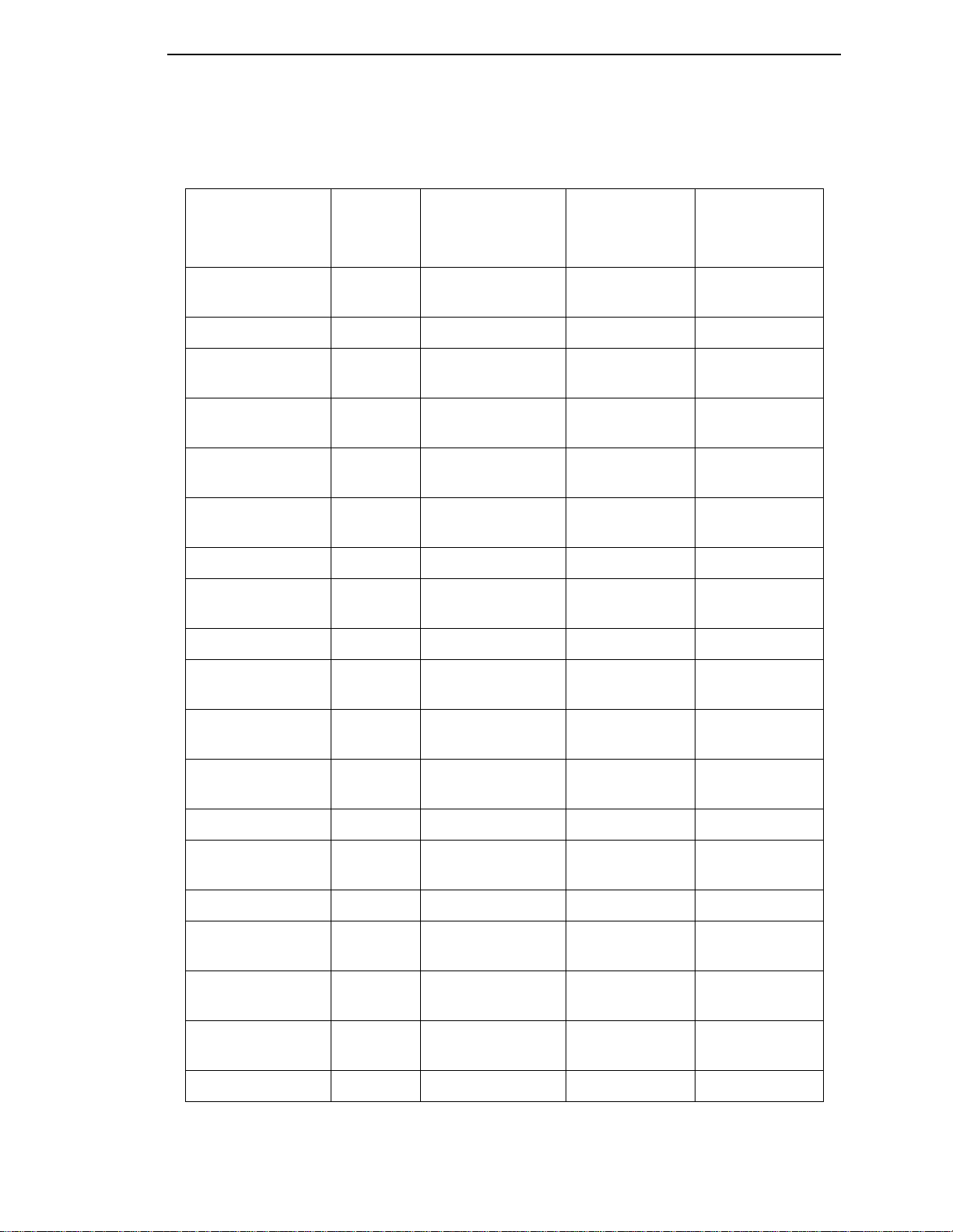
Table 1. P5000 Printers
How to Identify the Printer
Model Number
Print
Speed
Enclosure Hammer Bank
P50KA 585 lpm Pedestal 91 Hammers
Data
Controller
Clock Speed
25 MHz
Kanji / Hanzi
P5005 475 lpm Pedestal 28 Hammers 25 MHz
P5005-QA 475 lpm Pedestal w/Quick-
28 Hammers 25 MHz
Access Cover
P5005-12 475 lpm Pedestal 28 Hammers,
25 MHz
12 MIL tips
P5005-12-QA 475 lpm Pedestal w/Quick-
Access Cover
P51KA 585 lpm Table Top 91 Hammers
28 Hammers,
12 MIL tips
25 MHz
25 MHz
Kanji / Hanzi
P5205 475 lpm Cabinet 28 Hammers 25 MHz
P5205-12 475 lpm Cabinet 28 Hammers,
25 MHz
12 MIL tips
P5005A 500 lpm Pedestal 28 Hammers 25 MHz
1
P5005A-QA 500 lpm Pedestal w/Quick-
28 Hammers 25 MHz
Access Cover
P5005A-12 500 lpm Pedestal 28 Hammers,
25 MHz
12 MIL tips
P5005A-12-QA 500 lpm Pedestal w/Quick-
Access Cover
28 Hammers,
12 MIL tips
25 MHz
P5205A 500 lpm Cabinet 28 Hammers 25 MHz
P5205A-12 500 lpm Cabinet 28 Hammers,
25 MHz
12 MIL tips
P5005B 500 lpm Pedestal 28 Hammers 40 MHz
P5005B-QA 500 lpm Pedestal w/Quick-
28 Hammers 40 MHz
Access Cover
P5005B-12 500 lpm Pedestal 28 Hammers,
40 MHz
12 MIL tips
P5005B-12-QA 500 lpm Pedestal w/Quick-
Access Cover
28 Hammers,
12 MIL tips
40 MHz
P5205B 500 lpm Cabinet 28 Hammers 40 MHz
13
Page 14
Chapter 1 P5000 Printers
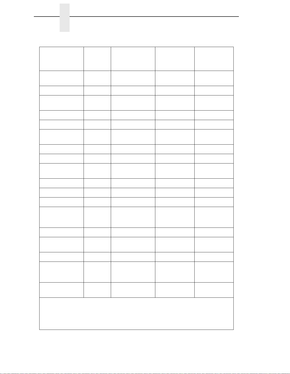
Table 1. P5000 Printers
Model Number
Print
Speed
Enclosure Hammer Bank
P5205B-12 500 lpm Cabinet 49 Hammers,
Data
Controller
Clock Speed
40 MHz
12 MIL tips
P5008 800 lpm Pedestal 49 Hammers 25 MHz
P5008-QA 800 lpm Pedestal w/Quick-
49 Hammers 25 MHz
Access Cover
P5208 800 lpm Cabinet 49 Hammers 25 MHz
P500 900 lpm Pedestal 49 Hammers 25 MHz
P5009-QA 900 lpm Pedestal w/Quick-
49 Hammers 25 MHz
Access Cover
P5209 900 lpm Cabinet 49 Hammers 25 MHz
P5010 1000 lpm Pedestal 60 Hammers 40 MHz
P5010-QA 1000 lpm Pedestal w/Quick-
60 Hammers 40 MHz
Access Cover
P5210 1000 lpm Cabinet 60 Hammers 40 MHz
1
P5212 1200 lpm Cabinet 91 Hammers 25 MHz
P5214 1400 lpm Cabinet 91 Hammers 40 MHz
P5214-SS 1400 lpm Cabinet
91 Hammers 40 MHz
w/SureStak
Paper Stacker
P5015 1500 lpm Pedestal 102 Hammers 40 MHz
P5015-QA 1500 lpm Pedestal w/Quick-
102 Hammers 40 MHz
Access Cover
P5215 1500 lpm Cabinet 102 Hammers 40 MHz
P5215-SS 1500 lpm Cabinet
102 Hammers 40 MHz
w/SureStak
Paper Stacker
P52KA 585 lpm Cabinet 91 Hammers
40 MHz
Kanji / Hanzi
1
The microprocessor of the Data Controller unit on the CMX controller board runs at 25
MHz or 40 MHz, depending on printer model. This means there are two kinds of CMX
controller board for these printers, used as indicated in Table 1. The 40 MHz controller
board, however, is compatible with all models that use the 25 MHz board and should be
used if the CMX board is replaced.
14
Page 15

Important Maintenance Notes
To ensure the best performance of the printer, remember these maintenance
principles whenever you service the printer.
How to Identify the Printer
CAUTION
Failure to observe these guidelines can result in damage to the
equipment.
• Do not
1) the original shuttle frame assembly or platen has been replaced with a
new or rebuilt unit, or
2) you are instructed to do so in a troubleshooting procedure.
• Never bend or tweak hammer springs. Always handle hammer springs by
the thick mounting base. The hammer springs and hammer tips are
delicate and precisely aligned.
• Use only
can lead to ink migration problems, degraded print quality, and expensive
damage to the printer.
• Do not close the forms thickness lever too tightly. Closing the forms
thickness lever too tightly can lead to smearing, degraded print quality,
paper jams, and damage to the platen and shuttle assembly.
About This Manual
This is a field service maintenance manual. It is designed so that you can
locate maintenance information quickly.
This manual does not explain how to install, operate, or configure the printer.
That information is in the
adjust the platen gap unless
the ribbons specified in Appendix B. Use of incorrect ribbons
User’s Manual.
This manual does not explain how to program application software for
operation with the printer. Programming information for the protocols used by
the printer is in the appropriate programmer’s reference manual:
•
LinePrinter Plus
Defines host control codes for the LinePrinter Plus emulations.
•
Character Sets Reference Manual
Information about and examples of the character sets available in
Printronix line matrix printers.
•
Network User’s Manual
Information about network protocols, configuration, and network
operation.
•
Coax/Twinax Programmer’s Reference Manual
Defines host control codes and character sets for the optional coax/twinax
emulations.
•
ANSI Programmer’s Reference Manual
Defines host control codes and character sets for the ANSI emulation.
•
IPDS Twinax Emulation Programmer’s Reference Manual
An overview of Intelligent Printer Data Stream™ (IPDS) features,
commands, and diagnostics.
Programmer’s Reference Manual
15
Page 16

Chapter 1 About This Manual
•
IGP/PGL Programmer’s Reference Manual
Describes the optional IGP Printronix emulation. The IGP Printronix
emulation allows the user to create and store forms; generate logos, bar
codes, and expanded characters; create other graphics, and merge
graphics with alphanumeric data as a document is printed.
•
IGP/VGL Programmer’s Manual
Describes the optional Code V Printronix emulation. The Code V
Printronix emulation allows the user to create and store forms; generate
logos, bar codes, and expanded characters; create other graphics, and
merge graphics with alphanumeric data as a document is printed.
How to Use This Manual
1. Find the procedure or information you need in the Table of Contents or the Index.
2. Read the entire procedure before you work on the printer.
3. Gather the parts and tools you will need.
4. Make sure you understand all safety notices before you start a task. (See below.)
WARNING
CAUTION
IMPORTANT
IMPORTANT
Notes and Notices
For your safety and to protect valuable equipment, read and comply with all
information highlighted under notes and notices. The heading of a notice
indicates the kind of information it contains:
Conditions that could hurt you and damage equipment.
Conditions that could damage equipment.
Information vital to proper operation and maintenance of the printer.
NOTE: Notes contain tips for efficient operation, maintenance, and
troubleshooting.
The Safety Notices on page 17 apply at all times when you are working
on the printer. Please read them now.
Printing Conventions in This Manual
Control panel keys and indicators are highlighted in UPPERCASE BOLD
PRINT.
Example: Press the CANCEL key, then press the ON LINE key.
LCD (Liquid Crystal Display) messages are set off by quotation marks (“ “).
Example: Press the ON LINE key. “OFF LINE” appears on the LCD.
16
Control panel key combinations are indicated by the + (plus) symbol.
Example: Press
means Press the
= + >.
=(UP) key and the >(DOWN) key at the same time.
Page 17

Safety Notices
Printing Conventions in This Manual
WARNING
WARNING
WARNING
WARNING
WARNING
Always disconnect the AC power cord from the printer or power source
before performing any maintenance procedure. Failure to remove power
could result in injury to persons or damage to equipment. If you must
apply power during maintenance, you will be instructed to do so in the
maintenance procedure.
Always disconnect the AC power cord before cleaning the printer.
To prevent injury from electric shock, wait at least one minute after
shutting off power before removing the power supply circuit board.
Wear a properly grounded static wrist strap when handling the power
supply board. Handle the board by the sides. Do not touch components
or flex the board during removal/installation.
Over time, the upper edge of the paper ironer can become sharp. To
avoid cutting yourself, handle the paper ironer on the sides.
Hold the printer cover securely while disengaging the gas spring
assembly.
Hinweise zur Sicherheit
Bevor Sie anfällige Wartungsarbeiten durchführen, müssen Sie zuerst
immer das Netzkabel aus der Steckdose ziehen. Wird das Netzkabel
nicht herausgezogen, können Verletzungen oder Geräteschäden
entstehen. Falls die Wartungsarbeit Stromzufuhr erfordert, wird im
Wartungsablauf darauf hingewiesen.
VORSICHT
VORSICHT
Ziehen Sie das Netzkabel aus der Steckdose, bevor Sie den Drucker
reinigen.
VORSICHT
Um Verletzungen durch Elektroschocks zu vermeiden, warten Sie
mindestens eine Minute nach Stromausschaltung, bevor Sie die
elektrische Schaltkarte entfernen. Bitte immer einen geerdeten,
statischen Handgelenkriemen tragen, wenn Sie die elektrische
Schaltkarte handhaben. Halten Sie die Karte nur an den seitlichen
Auswurfshebeln. Während des Herausnehmens/Installierens dürfen die
Komponenten der Karte nicht berührt oder gebogen werden.
VORSICHT
Die obere Kante der Papierschiene wird mit der Zeit scharf. Halten Sie
die Schiene deshalb an den Seiten, damit Sie sich nicht schneiden.
VORSICHT
Behalten Sie die Druckerabdeckung sicher im Griff, wenn Sie das
Gasfederpaket entfernen.
17
Page 18

Chapter 1 Controls and Indicators
Controls and Indicators
Electrical Controls and Indicators, Cabinet Models (Figure 2)
Switch or
Indicator
Power Switch Turns printer on and off: 1 = on, 0 = off. This switch is also a circuit breaker.
Status
Indicator
LCD Liquid Crystal Display. Displays pri nter status messages, fault messages, and
ON LINE/
CLEAR
PAPER
ADVANCE
VIEW /
EJECT
CANCEL Clears all data from the print buffer (if enabled in the MAINT/MISC menu).
= (UP)
On when the print er is on -lin e, o f f w h en th e printer is off-line. Flashes to indicate a
fault or warning.
menus which permit user to set various configurations.
Toggles the printer on-line and off-line. Clears the printer after a fault is corrected
and returns the printer to off-line state.
Prints any data in the buffer then moves paper up one line at the currently active
line spacing. If pressed longer than 1/2 second, moves paper to the next Top Of
Form as defined by the currently active form length.
Moves the current print position to the tractor area for viewing. When paper is in
VIEW position, “Printer in View” displays and microstep adjustment feature is
active. (See UP and DOWN keys.) Holding key down for more than 1/2 second
invokes EJECT and paper is advanced two pages. (EJECT can be disabled via
the menus.) Pressing key a second time moves paper back to the print position
from either VIEW or EJECT position.
Displays next higher level of a configuration menu. In VIEW mode, moves paper
up 1/72 inch. (See VIEW / EJECT key.)
Function
Active
On-line
Active
Off-line
ää
ää
ää
ää
ää
ä
ää
> (DOWN)
< (NEXT)
; (PREV)
SET TOF Moves paper downward from TOF alignment mark to the print station and sets this
PRT CONFIG Prints the current printer configuration.
JOB SELECT Allows fast selection of any stored configuration. Repeated pressing scrolls
ENTER Enters an option disp layed on th e LCD into p rinter no n-volatile memory. Starts and
;+<
Displays next lower level of a configuration menu. In VIEW mode, moves paper
down 1/72 inch. (See VIEW / EJECT key.)
Displays the next option in a configuration menu.
Displays the previous option in a configuration menu.
as the first line of print on a page, independent of forms length. If there are data in
the buffers, the printer slews to the page position where printing left off and prints
the data.
through all saved configurations. Press ENTER to select the displayed
configuration. (ENTER does not have to be unlocked for this function.)
stops printer tests, sets a value, or prints the configuration. This key is locked and
unlocked by a user-selectable key combination. (Refer to the
Resets the printer by reloading the power-up configuration and resetting the
internal state.
User’s Manual
.)
ää
ä
ä
ä
ä
ä
ä
18
Page 19
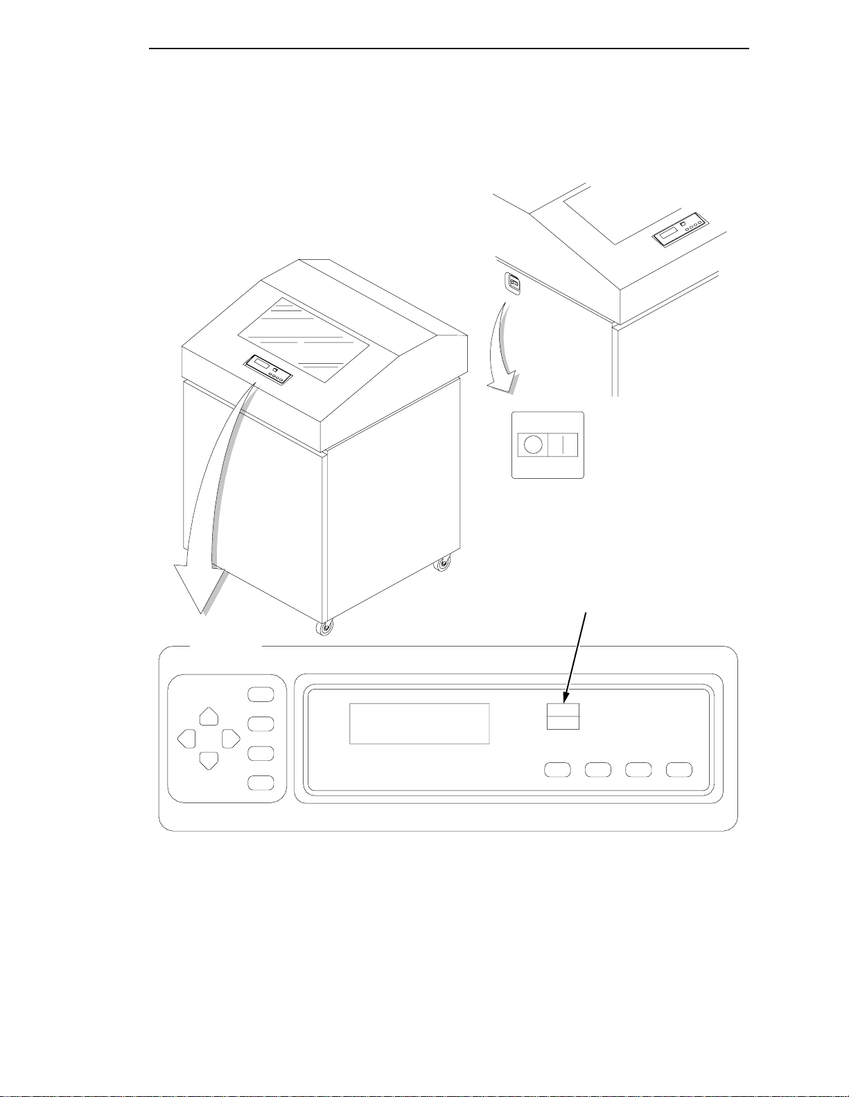
Printing Conventions in This Manual
(Off) (On)
Raise printer
cover to use
these keys.
UP
PREV
DOWN
NEXT
SET TOF
PRT CONFIG
JOB SELECT
ENTER
LCD
Power Switch
Status Indicator
ON LINE
CLEAR EJECT
PAPER
ADVANCE
VIEW
CANCEL
Figure 2. Electrical Controls, Cabinet Models
19
Page 20

Chapter 1 Controls and Indicators
Electrical Controls and Indicators, Pedestal Models (Figure 3)
Switch or
Indicator
Power Switch Turns printer on and off: 1 = on, 0 = off. This switch is also a circuit breaker.
Status
Indicator
LCD Liquid Crystal Display. Displays pri nter status messages, fault messages, and
ON-LINE
CLEAR
PAPER
ADVANCE
VIEW
EJECT
CANCEL Clears all data from the print buffer (if enabled in the MAINT/MISC menu).
↑
UP
On when the printer is on -lin e, o f f w h en th e p rinte r is off-line. Flashes to indicate a
fault or warning.
menus which permit user to set various configurations.
Toggles the printer on-line and off-line. Clears the printer after a fault is corrected
and returns the printer to off-line state.
Prints any data in the buffer then moves paper up one line at the currently active
line spacing. If pressed longer than 1/2 second, moves paper to the next Top Of
Form as defined by the currently active form length.
Moves the current print position to the tractor area for viewing. When paper is in
VIEW position, “Printer in View” displays and microstep adjustment feature is
active. (See UP and DOWN keys.) Holding key down for more than 1/2 second
invokes EJECT and paper is advanced two pages. (EJECT can be disabled via
the menus.) Pressing key a second time moves paper back to the print position
from either VIEW or EJECT position.
Displays next higher level of a configuration menu. In VIEW mode, moves paper
up 1/72 inch. (See VIEW / EJECT key.)
Function
Active
On-line
Active
Off-line
ää
ää
ää
ää
ää
ä
ää
↓
DOWN
→
NEXT
←
PREV
SET
TOF
PRT
CONFIG
JOB
SELECT
ENTER Enters an option disp layed on th e LCD into p rinter non -volatile memory. Starts and
← + → Resets the printer by reloading the power-up configuration and resetting the
Displays next lower level of a configuration menu. In VIEW mode, moves paper
down 1/72 inch. (See VIEW / EJECT key.)
Displays the next option in a configuration menu.
Displays the previous option in a configuration menu.
Moves paper downward from TO F ali gnment m ark to the p rint s tation and s ets this
as the first line of print on a page, independent of forms length. If there are data in
the buffers, the printer slews to the page position where printing left off and prints
the data.
Prints the current printer configuration.
Allows fast selection of any stored configuration. Repeated pressing scrolls
through all saved configurations. Press ENTER to select the displayed
configuration. (ENTER does not have to be unlocked for this function.)
stops printer tests, sets a value, or prints the configuration. This key is locked and
unlocked by a user-selectable key combination. (Refer to the
internal state.
User’s Manual
.)
ää
ä
ä
ä
ä
ä
ä
20
Page 21
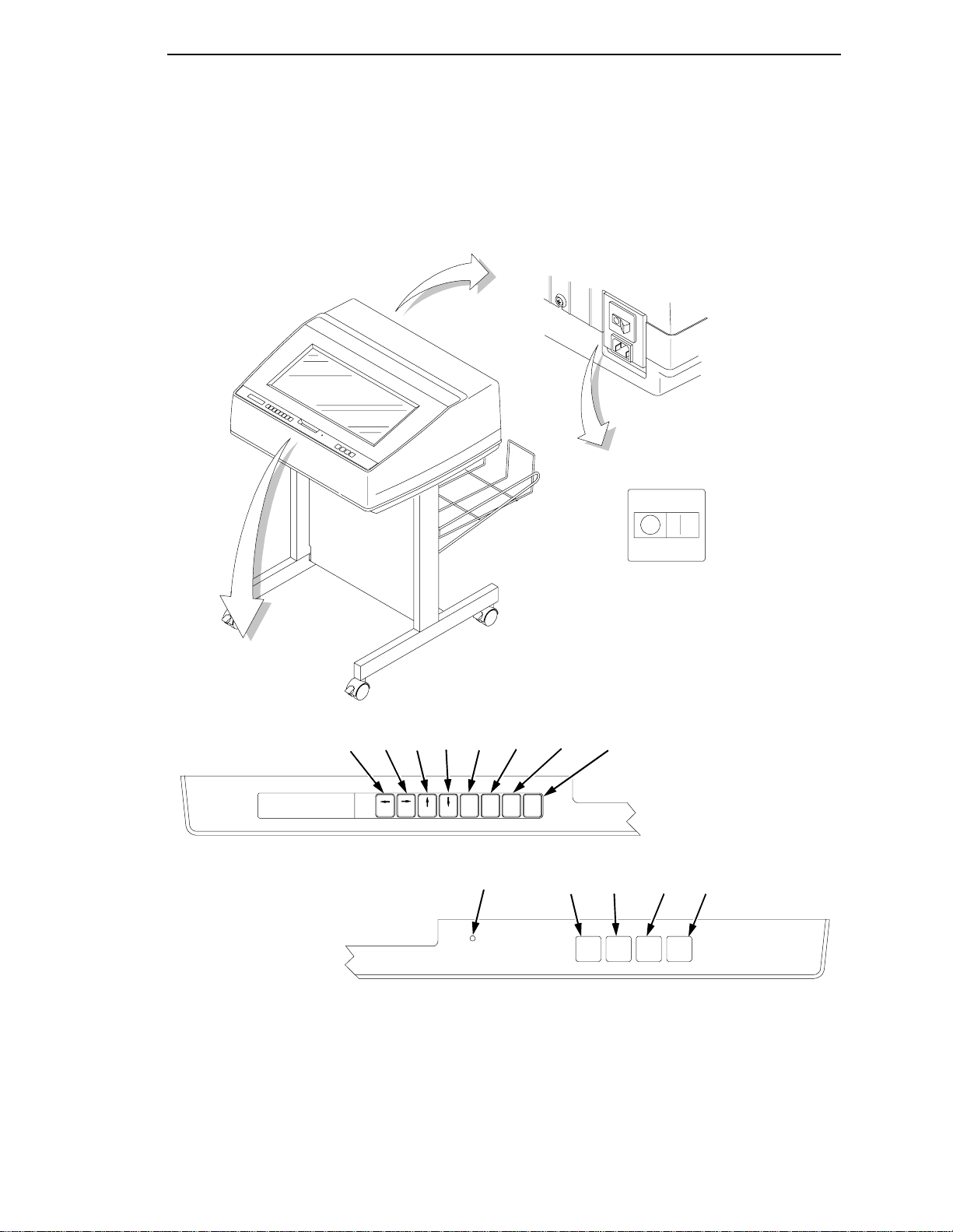
Printing Conventions in This Manual
(Off) (On)
LCD
Power Switch
JOB
PRT
SET
DOWNUPNEXTPREV
TOF
SET
PRT
UP DOWN
TOF
CONFIG
NEXT
PREV
Status Indicator
CONFIG
JOB
SELECT
ENTER
SELECT
ON-LINE
ENTER
CLEAR
PAPER
ADVANCE
ON-LINE PAPER VIEW CANCEL
CLEAR ADVANCE EJECT
VIEW
EJECT
CANCEL
Figure 3. Electrical Controls, Pedestal Models
21
Page 22
Chapter 1 Controls and Indicators
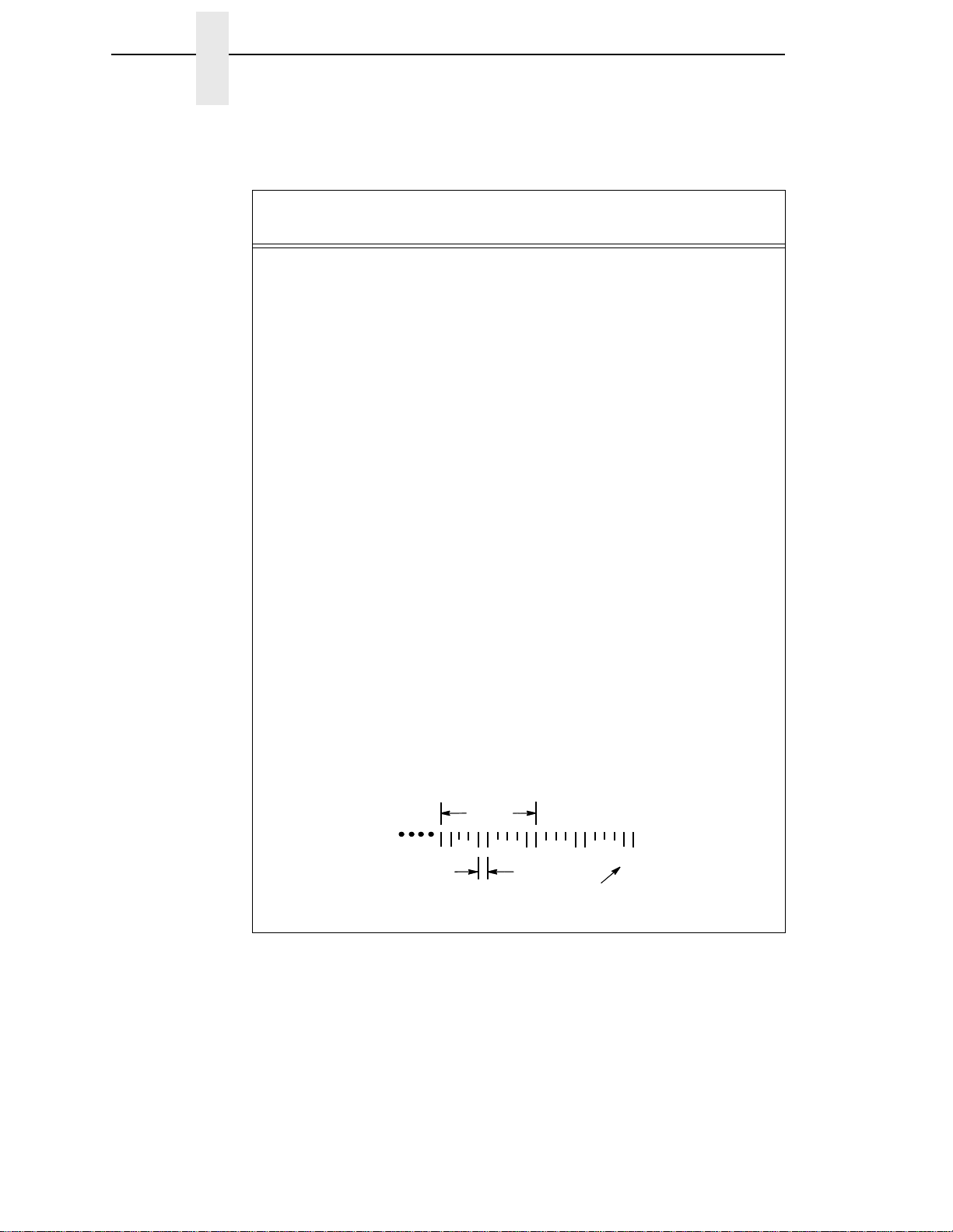
Mechanical Controls and Indicators, All Models (Figure 6)
Control or
Indicator
Forms Thickness
Lever
Sets the platen for paper and forms of different
thicknesses. Lever must be fully opened (raised) to
Function
load or unload paper.
Paper Supports Help prevent paper jams by supporting inner sections
of paper. They are positioned manually by sliding
them along the shafts.
Forms Thickness
Pointer and Scale
Indicates relative thickness of forms and paper. Set
this lever at A for thin (single-part) forms, B for thicker
forms, and so on.
Tractors (2) Hold and feed paper. Used to set side margin and
position paper horizontally.
Tractor Locks (2) Lock tractors in position.
Horizontal
Adjustment Knob
Vertical Position
Knob
Allows fine positioning of left print margin. Moves
paper and tractors left or right.
Used to set top of form or first line to be printed.
Rotate this knob to move paper vertically. Works
when forms thickness lever is open.
Ribbon Loading
Path Diagrams
Instructions showing how to load the ribbon correctly.
One diagram is cast in relief on the shuttle cover, and
another is printed on the paper scale.
Paper Scale A horizontal scale graduated in tenths of an inch,
useful for setting paper margins counting text
columns. (See below.)
1 inch
110 20
0.1 inch
Column
Number
22
Page 23
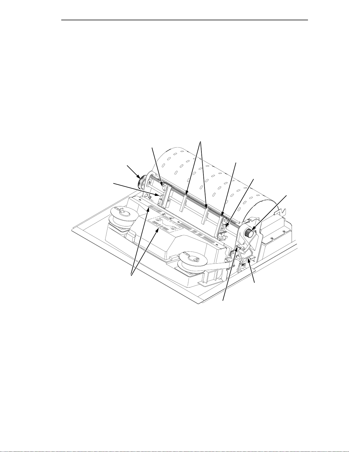
Left Tractor
Printing Conventions in This Manual
Paper
Supports
Tractor Lock
Horizontal
Adjustment
Knob
Ribbon Loading
Path Diagrams
Right Tractor
Tractor Lock
Vertical
Position
Knob
Forms Thickness
Lever and Scale
Forms
Thickness
Pointer
Figure 4. Mechanical Controls and Indicators, All Models
23
Page 24

Chapter 1 Tools, Test Equipment, and Supplies
Tools, Test Equipment, and Supp lies
For field level maintenance of the printer, you will need these tools:
Adapter, 1/4 in. hex to 1/4 in. square, Utica
Alcohol, anhydrous
Allen Wrench, 1/16 inch
Allen Wrench, 3/32 inch
Allen Wrench, 7/64 inch
Allen Wrench, 5/64 inch
ESD Wrist Strap
Feeler Gauge, .010 inch
Feeler Gauge, .011 inch
Feeler Gauge, .040 inch
Force Gauge, (Chatillon NY, Gauge-r, 0-20 lb., CAT 719-20)
HW-18
Hex bit, 3/16 in., torque screwdriver
Hex bit, 3/32 in., torque screwdriver
Hex bit, 5/32 in., torque screwdriver
Hex bit, 5/64 in., torque screwdriver
Lubricant, Bearing (Printronix P/N 101805-001)
Nut Driver, 1/4 inch
Nut Driver, 5/16 inch
Nut Driver or Open End Wrench, 7/32 inch
Open End Wrench, 5/16 inch
Pliers, Grip Ring, External
Screwdriver, flat tip
Screwdriver, Phillips, #1
Screwdriver, Phillips, #2
Screwdriver, Torque, Utica TS-35
Tie Wraps, 4 inch
Torx
T-10 Driver
24
Page 25

2 Preventive Maintenance
Cleaning the Printer
The printer is designed to require very little maintenance. Aside from normal
replenishment of paper and ribbons, the only preventive maintenance
required is periodic cleaning.
Because operating conditions vary widely, the user must determine how often
to clean the printer.
Since there is no guarantee that the user will clean the printer regularly, you
should clean the printer whenever you are called to service it. The cleaning
procedures in this chapter pertain to all models.
WARNING
CAUTION
Always disconnect the AC power cord before cleaning the printer.
Do not use abrasive cleaners, particularly on the window.
Do not drip water into the printer. Damage to the equipment will result.
Do not spray directly onto the printer when using spray solutions. Spray
the cloth, then apply the dampened cloth to the printer.
Do not vacuum the circuit boards.
Cleaning the Outside Surfaces
1. Power off the printer.
CAUTION
2. Disconnect the AC power cord from the printer or the power source.
3. Remove paper and the ribbon.
4. Dampen a clean, lint-free cloth with water and a mild detergent or with
window cleaning solution. The cloth must be damp, not wet. Wipe down
the outside surfaces of the printer.
5. Dry the outside surfaces with a clean, lint-free cloth.
6. Open the printer cover.
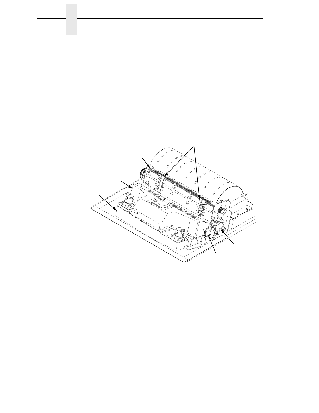
7. Using a soft-bristled, non-metallic brush (such as a toothbrush), brush
paper dust and ribbon lint off the tractors, shuttle cover assembly, base
casting, and ribbon guides. Vacuum up the residue. (See Figure 5.)
8. Wipe the splined shaft with a soft cloth.
To avoid corrosion damage, use only alcohol when cleaning printer
mechanical elements, and make sure the cleaning solution contains no
water.
25
Page 26
Chapter 2 Cleaning the Outside Surfaces
9. Using a cloth dampened (not wet) with alcohol, clean the ribbon guides.
10. Vacuum up dust and residue from the lower cabinet.
11. Wipe the interior of the lower cabinet with a clean, lint-free cloth
dampened with water and a mild detergent or window cleaning solution.
12. Dry the cabinet interior with a clean, lint-free cloth.
13. Clean the shuttle frame assembly, as described in the next section.
3
4
2
1
NOTE: Cabinet model
shown. Procedure is the
same for pedestal model.
Legend:
1) Base Casting
2) Shuttle Cover Assembly
3) Splined Shaft
4) Tractors
5) Forms Thickness Lever
6) Ribbon Guide
5
6
26
Figure 5. Cleaning Inside the Cabinet or Top Cover
Page 27
Cleaning the Shuttle Frame Assembly
1. Remove the shuttle cover assembly (page 160).
2. Remove the shuttle frame assembly (page 198).
3. Remove the paper ironer (page 176).
WARNING
CAUTION
CAUTION
Over time, the upper edge of the paper ironer can become sharp. To
avoid cutting yourself, handle the paper ironer on the sides.
4. Moisten a clean, soft cloth with alcohol. Wipe the paper ironer to remove
lint, ink, and paper residue.
5. Install the paper ironer (page 176).
6. Remove the hammer bank / ribbon mask cover assembly (page 157).
The ribbon mask is thin and easily bent. Be careful not to crease or kink
the ribbon mask when handling and cleaning it.
7. Moisten a clean, soft cloth with alcohol. Wipe the hammer bank cover and
ribbon mask to remove lint, ink, and paper residue. Clean the holes in the
cover strips. Carefully wipe between the hammer bank cover and the
ribbon mask (early models).
Do not use any solvents or liquids to clean the hammer tips. Clean the
hammer tips gently—too much pressure can chip them.
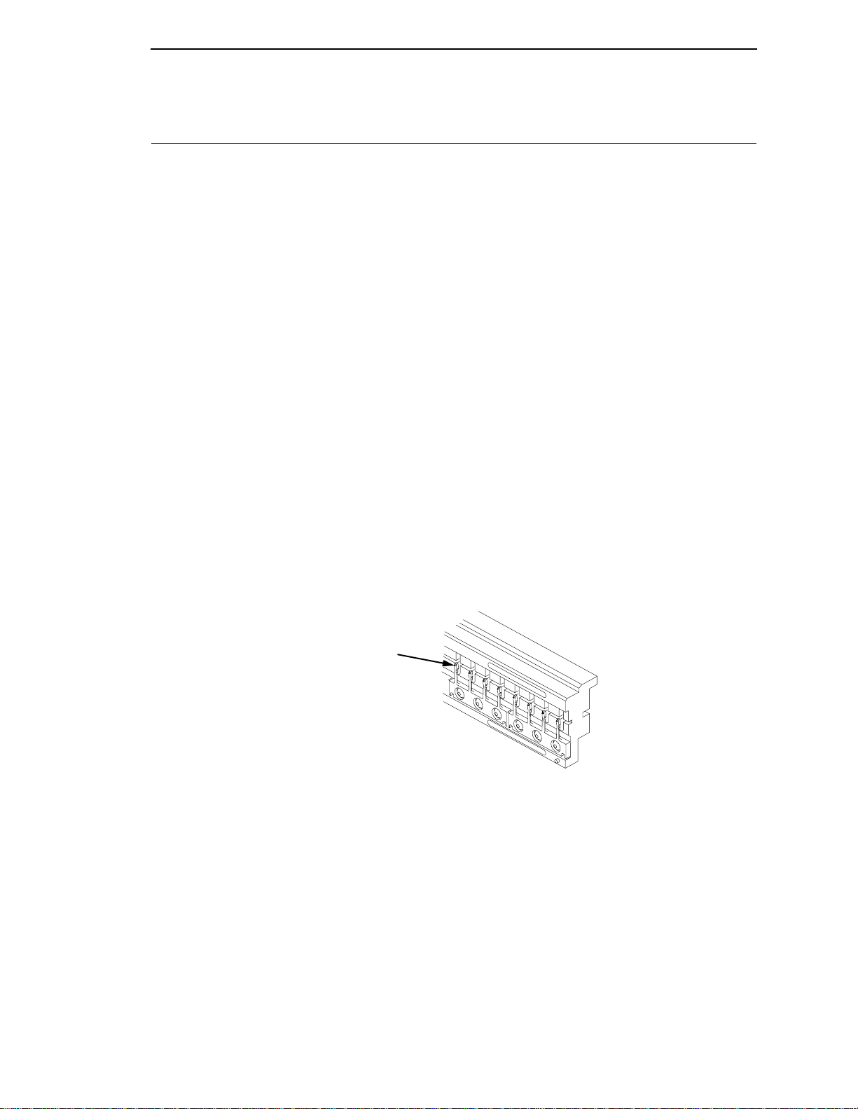
8. Using a stiff, non-metallic brush (such as a toothbrush), gently brush the
hammer tips to remove lint and ink accumulations. (See Figure 6.)
Vacuum up any residue.
NOTE: P5005 hammer bank is
shown. Procedure is the same
1
for all hammer banks.
CAUTION
Legend:
1) Hammer Tip
Figure 6. Cleaning the Hammer Tips
The hammer bank contains a strong magnet. To prevent damage to the
hammer tips, do not let the hammer bank cover assembly snap into
place as the hammer bank magnet attracts it. Any impact of the cover
against the hammer bank can break hammer tips.
9. Install the hammer bank / ribbon mask cover assembly (page 157).
10. Install the shuttle frame assembly (page 198).
27
Page 28
Chapter 2 Cleaning the Card Cage Fan Assembly
11. Install the shuttle cover assembly (page 160).
12. Clean the card cage fan assembly, as described in the next section.
Cleaning the Card Cage Fan Assembly
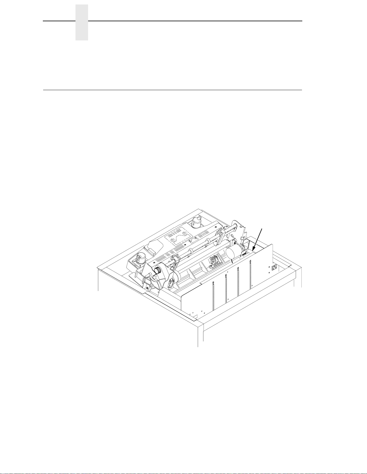
1. Cabinet Models: Remove the paper path (page 177).
Pedestal Models: Remove the top cover assembly (page 161).
2. Vacuum the card cage fan assembly and surrounding areas to remove
paper particles, dust, and lint. (See Figure 7.)
3. Cabinet Models: Install the paper path (page 177)
Pedestal Models: Install the top cover assembly (page 161).
4. Return the printer to normal operation (page 107).
NOTE: Cabinet model show n.
Procedure is the same for
pedestal model.
1
28
Legend:
1) Card Cage Fan Assemb.y
Figure 7. Cleaning the Card Cage Fan Assembly
Page 29

3 Troubleshooting
Introduction
This chapter lists fault messages and symptoms, and provides procedures for
troubleshooting printer malfunctions.
Always have the
manual does not cover printer operation or configuration. You must operate
the printer to check its performance, and sometimes you may have to
reconfigure it.
T roubleshooting Aids
Troubleshooting is faster and more effective if you understand the equipment
and make use of all available tools.
This manual provides a number of troubleshooting aids to help you isolate
printer malfunctions:
• “Start Here” Logic Tree page 30
• Troubleshooting Display Messages page 31
• Message List page 31
• Troubleshooting Other Symptoms page 36
• General Symptom List page 36
• Troubleshooting Procedures page 38
• Diagnostic Printer Tests page 92
• Hex Code Printout page 95
User’s Manual
handy when you troubleshoot because this
• ASCII Character Set page 97
• The Power On Sequence page 99
• Appendix A: Wire Data page 259
29
Page 30
Chapter 3 Start Here...
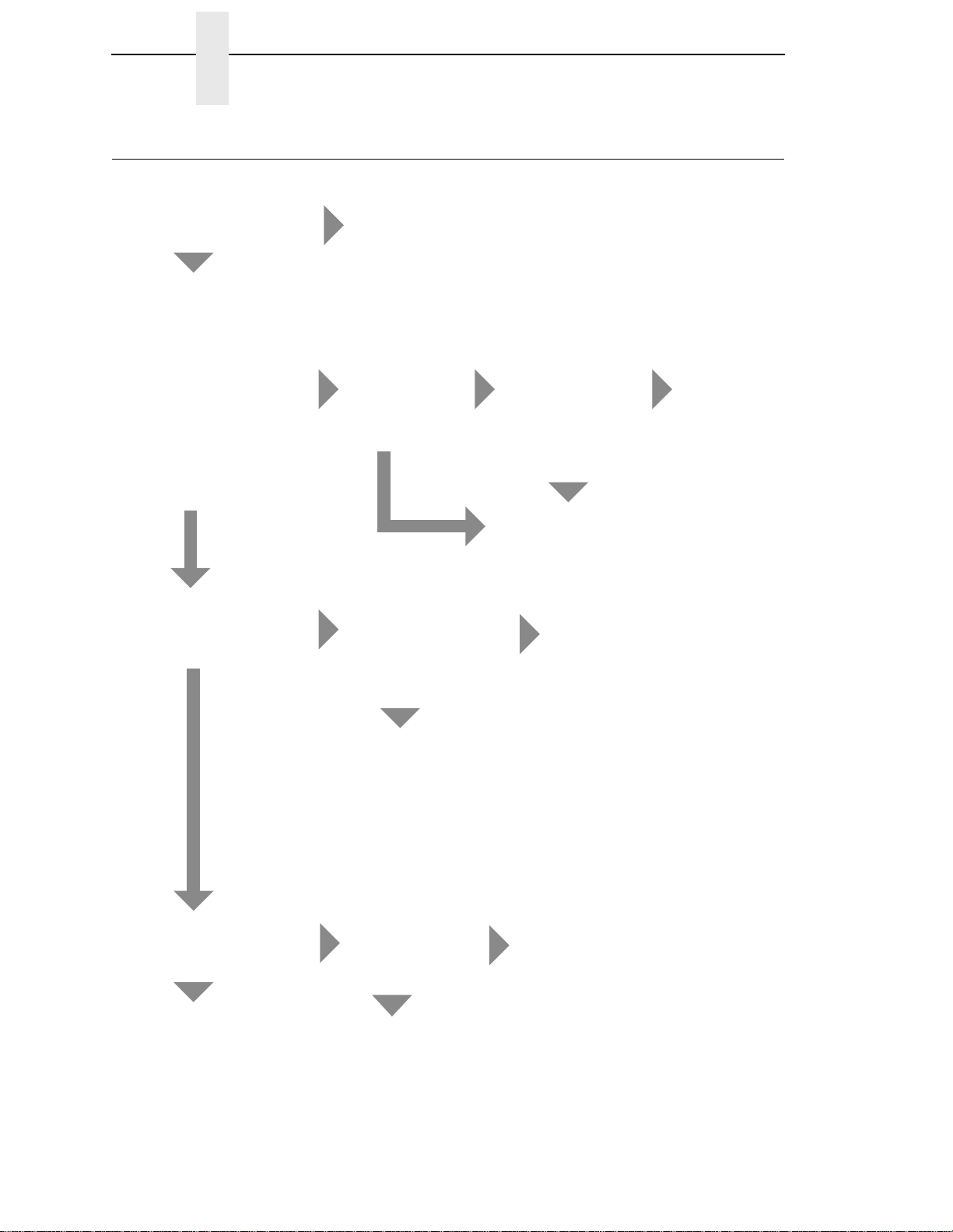
Start Here...
Are you here because of an
error message?
NO
Power on the printer and
observe the control panel
for the following sequence
of events (retry as
required):
1. All blac k squares
appear on the display.
2. Display goes blank.
3. TESTING HARDWARE
PLEASE WAIT appears
on display.
Power on the printer.
Did steps 1, 2, and 3
occur?
NO
Did the fans come on after
10 seconds?
NO
YES
YES
YES
Go to Troubleshooting Display
Messages, page 31.
Did the status
indicator lamp
After about 10
seconds did
the fans come
on?
NO
Press ON LINE.
Press PRT CONFIG.
Press ENTER.
Does machine
configuration
print?
YES
come on and
ONLINE appear
on the display? (If
default is
OFFLINE, status
indicator will not
come on.)
Go to Printer
does not
initialize, page 71.
YES
YES
NO
Go to the Control
Panel section of
Table 3: page 36
Printer initialized
successfully.
Other symptoms
are listed in
Table 3: page
36.
Did ANY of steps 1 thru 3
occur?
NO
Go to No power, and
control panel is blank,
and card cage fan is not
running, page 62.
YES
NO
The Control Panel
is not functioning
(Table 3: page 36)
—OR—
Printer does not
initialize, page 71.
Are there black
squares on the
control panel?
NO
Go to Printer does not
initialize, page 71.
YES
Go to Black squares
on control panel
display, page 44.
30
Page 31

T roubleshooting Display Messages
How to Clear LCD Messages
WARNING
Always disconnect the AC power cord from the printer before doing a
maintenance procedure. Failure to remove power could result in injury
to you or damage to equipment. If you must apply power during
maintenance, you will be instructed to do so in the maintenance
procedure.
Three kinds of messages appear on the Liquid Crystal Display (LCD):
• Status messages
• Configuration menus and menu options
• Fault messages
NOTE: Most fault messages are cleared from the LCD by correcting the fault
condition and then pressing the CLEAR key. Fault messages that
can only be cleared by shutting down and restarting the printer are
indicated by an asterisk (*) appended to the message.
If printer logic detects a fault condition, three things happen:
• The status indicator on the control panel flashes on and off.
• The audible alarm beeps if it is enabled. Press CLEAR to silence the
alarm.
• The control panel LCD displays a fault message.
How to Clear LCD Messages
Find the message in the Message List below, go to the troubleshooting
procedure, and follow the numbered instructions. After correcting an error,
press the CLEAR key to clear the message and place the printer in the offline state.
If an error is not cleared, the printer will try to print again but will display the
error message until the error is cleared.
Table 2: Message List
Symptom
06 HOST REQUEST page 39
08 HOLD PRINT
TIMEOUT
8.5V POWER FAIL * page 39
15 COMM CHECK page 39
15V CTL FAIL* page 40
22 INVALID ADDR page 40
23.5V CTL FAIL* page 40
Troubleshooting
Procedure
page 39
31
Page 32

Chapter 3 Troubleshooting Display Messages
Table 2: Message List
Symptom
31 PAPER OUT
TIMEOUT
32 PAPER JAM
TIMEOUT
33 PLATEN OPEN
TIMEOUT
34 RIBBON STALL
TIMEOUT
48V PWR FAIL* page 43
ACCESS NULL PTR* page 43
ACTIVATE LOST page 44
A TO D OVERRUN* page 44
BUFFER OVERRUN page 45
CLEAR PAPER JAM page 46
CLEARING PROGRAM
FROM FLASH
Troubleshooting
Procedure
page 41
page 41
page 42
page 42
page 49
CLOSE PLATEN page 49
COIL HOT page 49
CTL VOLT FAIL* page 51
DIAGNOSTIC
PASSED
DRVR CIR BAD* page 52
ERROR: DC PROGRAM
NOT VALID
ERROR: DRAM AT
ADDRESS XXXXXXXX
ERROR: EC PROGRAM
NOT VALID
ERROR: EC STOPPED
AT STATE XXXX
ERROR: FLASH
DID NOT PROGRAM
ERROR: FLASH
NOT DETECTED
ERROR: NO DRAM
DETECTED
page 51
page 52
page 53
page 53
page 53
page 53
page 54
page 54
32
Page 33

How to Clear LCD Messages
Table 2: Message List
ERROR: NVRAM
FAILURE
ERROR: PROGRAM
NEEDS MORE DRAM
ERROR: PROGRAM
NEEDS MORE FLASH
ERROR: PROGRAM
NOT COMPATIBLE
ERROR: PROGRAM
NOT VALID
ERROR: SECURITY PAL
NOT DETECTED
ERROR: SHORT AT
ADDRESS XXXX
ERROR: WRITING
TO FLASH
ERROR: WRONG
CHECKSUM
Symptom
Troubleshooting
Procedure
page 54
page 54
page 54
page 54
page 55
page 55
page 55
page 55
page 55
EXHAUST FAN FLT page 56
FIRMWARE ERROR page 56
FM HEADER ERROR page 57
FRAMING ERROR page 57
GRF CHK ERROR
PRESS STOP
HAM. COIL OPEN* page 57
HAMMER COIL BAD
#, #, #, #, ... etc.
HB NOT INSTALLD* page 58
HMR BANK FAN FLT page 58
ILL EXT BUS ACC* page 59
ILL INST ACCSS* page 60
ILLGL OPR ACCSS* page 60
INTAKE FAN FAULT page 60
INVALID ACTIVATE page 60
INVALID COMMAND page 61
page 57
page 58
33
Page 34

Chapter 3 Troubleshooting Display Messages
Table 2: Message List
Symptom
LO DRV. SHORT* page 61
LOAD PAPER page 62
LOADING PROGRAM
FROM PORT XX%
ONLINE
28 CU NOT ENAB
ONLINE
8344 FAIL ED
ONLINE
CU TIMED OUT
PAP BAD TABLE* page 63
PAP BSY TOO LNG* page 64
PAP FIFO OVERFL* page 64
PAP FIFO UNDRFL* page 64
PAP ILLGL ST* page 65
PAP INCMPL ENER* page 65
Troubleshooting
Procedure
page 62
page 63
page 63
page 63
PAP INVLD CMD* page 65
PAP INVLD PARM* page 65
PAP NOT SCHED* page 66
PAP NT AT SPEED* page 66
PAP UNEXP INT* page 66
PARAMETER ERROR page 66
PARITY ERROR page 67
PLAT INV CMD* page 67
PLAT INV PARM* page 67
PLAT INV STATE* page 67
PLEASE WAIT...
RESET IN PROGRESS
POWER SAVER MODE page 69
POWER SUPPLY HOT page 69
PRINTER HOT page 72
PROTECTED INSTR* page 73
page 68
34
Page 35

How to Clear LCD Messages
Table 2: Message List
Symptom
PWR SUPP VOLT* page 73
QUEUE OVERRUN page 73
RESTORING
BOOT CODE
RIB INVLD CMD* page 75
RIB INVLD STATE* page 75
RIBBON DRIVE page 75
RIBBON INK OUT
CHANGE RIBBON
SCS COMMAND ERROR page 76
SECURITY CODE VIOLATION page 77
SECURITY PAL NOT DETECTED page 76
SENDING PROGRAM
TO EC PROCESSOR
SF ERROR page 77
Troubleshooting
Procedure
page 73
page 76
page 77
SHUTL INV CMD* page 78
SHUTL INV PARM* page 78
SHUTTLE JAM page 79
SOFTWARE ERROR*
CYCLE POWER
STACK OVERFLOW* page 80
STACK UNDERFLOW* page 80
STACKER FAULT page 82
STACKER FULL page 83
STACKER JAM page 83
TABLE MISMATCH
DOWNLOAD AGAIN
TCB CORRUPTED* page 85
UNDEF INTERRUPT* page 86
UNDFNED OPCODE* page 86
UP DRV. SHORT* page 86
page 80
page 85
35
Page 36

Chapter 3 Troubleshooting Other Symptoms
T roubleshooting Other Symptoms
WARNING
Always disconnect the AC power cord from the printer before doing a
maintenance procedure. Failure to remove power could result in injury
to you or damage to equipment. If you must apply power during
maintenance, you will be instructed to do so in the maintenance
procedure.
Use standard fault isolation techniques to troubleshoot malfunctions not
indicated by display messages. These techniques are summarized below:
1. Ask the operator to describe the problem.
2. Verify the fault by running a diagnostic printer test or by replicating
conditions reported by the user.
3. Look for a match in the General Symptom List below. If you find a
match, go to the troubleshooting procedure and follow the numbered
instructions.
4. If you cannot find the symptom in the General Symptom List, use the
Half-Split Method to find the malfunction:
a. Start at a general level and work down to details.
b. Isolate faults to half the remaining system at a time, until the final half
is a field-replaceable part or assembly. (Troubleshooting aids are
listed on page 29.)
5. Replace the defective part or assembly. Do not attempt field repairs of
electronic components or assemblies. Most electronic problems are
corrected by replacing the printed circuit board assembly, sensor, or
cable that causes the fault indication. The same is true of failures traced
to the hammer bank: replace the entire shuttle frame assembly. It is not
field repairable.
6. Test printer operation after every corrective action.
36
7. Reinstall any parts you replaced earlier that did not solve the problem.
8. Stop troubleshooting and return the printer to normal operation when the
reported symptoms disappear.
Table 3: General Symptom List
Symptom
Communications Failures page 88
Jams
CLEAR P APER JAM message ins tead of LOAD PAPER when
printer is out of paper
CLEAR PAPER JAM message will not clear and paper does
not move
CLEAR PAPER JAM message will not clear but paper moves page 48
Troubleshooting
Procedure
page 47
page 47
Page 37

How to Clear LCD Messages
Table 3: General Symptom List
Symptom
Control Panel
Black squares on control panel page 44
Control panel blank page 50
Control panel keys do not work page 51
Control panel display shows garbled, broken characters page 51
Power Failures
No power, and control panel blank, and card cage fan not
running
Printer does not initialize page 71
Power Stacker
Printer does not detect presence of power stacker page 70
Stacker “chatters” at upper or lower limit page 80
Stacker does not stack properly page 81
Stacker elevator does not move page 81
Troubleshooting
Procedure
page 62
Stacker elevator moves by itself page 82
Stacker limit switch check page 83
Stacker motor check page 84
Stacker not operating page 70
Print Quality
Characters or dots are mis sing, smeared, too light, or too d ark page 45
Horizontal misalignment of characters (Dots or characters
move left or right from dot row to dot row or line to line) page 59
Randomly misplaced dots page 74
Vertical misalignment of characters:
1. Dots or characters move up or down from dot row to dot
row or line to line
2. Incorrect spacing from dot row to dot row or line to line
3. Characters randomly compressed and/or enlarged
Printer Operation
Downloads consistently fail page 52
Flash SIMM won’t copy page 57
page 86
Paper feeds poorly page 68
37
Page 38

Chapter 3 Troubleshooting Procedures
Table 3: General Symptom List
Symptom
Power on “hang” condition page 69
Printer does not print from the host page 71
Printer does not print self tests page 72
Reverse paper feed: platen does not open page 73
TOF is lost repeatedly page 85
Ribbon folding or feed problems page 75
Shuttle does not move page 77
Shuttle is noisy page 78
T roubleshooting Procedures
Troubleshooting procedures are listed in this section. Every troubleshooting
procedure has three parts:
Troubleshooting
Procedure
Ribbon
Shuttle
MESSAGE / MALFUNCTION — The LCD message or a description of
the malfunction
1. TEST / INSPECTION / EXPLANATION — Numbered steps that provide
information and tell you what to test or inspect
CORRECTIVE ACTION — Actions to take as a result of tests or
inspections
How to Use the Troubleshooting Procedu res
1. Find the message or symptom you want to troubleshoot in the Message
List (page 31) or the General Symptom List (page 36). The lists tell you
which page the troubleshooting procedure is on. Go to that page.
2. Start at step 1 of the troubleshooting procedure. Each step has corrective
action(s) indented below it.
3. Test the printer after every step and corrective action.
4. Work sequentially down the steps until the problem is solved.
STOP troubleshooting as soon as the problem is solved.
5. Reinstall any original parts you replaced earlier that did NOT solve the problem.
6. Reassemble the printer and give it a final test.
38
Page 39

The Procedures
The Procedures
06 HOST REQUEST Message
1. Status message: in CT emulation, the host computer or printer controller requires attention.
Not a printer problem.
08 HOLD PRINT TIMEOUT Message
1. Status message: in CT emulation, the printer was off-line more than 10
minutes and the “Intervention Required” parameter is set to “Send to
Host.”
Press ON LINE.
8.5V PWR F A IL* M essage
1. 8.5 Volt Power Failed. Internal power failure.
Cycle power. If the message appears, replace the power supply
board.
2. Power on the printer.
If the message appears, replace the CMX controller board. Record
the message and return it with defective CMX board.
3. Power on the printer.
If the message appears, replace the shuttle frame assembly.
15 COMM CHECK Message
1. Communication Check: a message that appe ar s in the CT emu lat ion
meaning the line is not active on a twinax interface. Power off the printer.
Check the twinax host data cable connection and twinax I/O cable
connection at the CT board.
Reseat the twinax host data cable connection and the twinax I/O
cable connection at the CT board.
2. Disconnect the twinax auto-termination cable from the printer. Test the
cable for the resistances shown in the Main Wire Harness Test Tables in
Appendix A.
If resistances are not correct, replace the twinax auto-termination
cable.
3. Power on the printer. Send a print job to the printer. Verify that all other
devices on the twinax line are working properly. (Refer to line problem
determination procedures, as recommended by the host system.)
If the message is gone, the host has reestablished communication
with the printer. If all other twinax devices work properly and the
39
Page 40

Chapter 3 Troubleshooting Procedures
message still appears, replace the expansion-CT board. Record the
message and return it with defective board.
15V CTL FAIL* Message
1. Controller Voltage Failure. Cycle Power. Run the print job again. If the message appears,
download the emulation software again (page 130).
2. Cycle power. Run the print job again. If the message appears, replace the flash memory.
3. Power on the printer. Run the print job again. If the message appears, replace the CMX controller board. Record
the message and return it with defective CMX board. Also check the
resistance of connectors P106/LRIB M and P107/RRIB M. (Refer to
the Main Wire Harness Test Tables in Appendix A.) If ribbon motor
resistance is not correct, replace the motor and/or the intermediate
cable, if installed.
4. Power on the printer. Run the print job again. If the message appears, replace the power supply board.
5. Power on the printer. If the message appears, replace the shuttle frame assembly.
22 INVALID AD DR Message
1. Invalid Address: poll time-out on the twinax interface indicating the unit
address is not recognized by printer.
Have the system administrator make sure the printer address is
correct.
23.5V CTL FAIL* Message
1. 23.5 Volt Controller Failed: a voltage failure on the CMX controller board. Cycle Power. Run the print job again. If the message appears,
download the emulation software again (page 130).
2. Cycle power. Run the print job again. If the message appears, replace the flash memory.
3. Power on the printer. Run the print job again. If the message appears, replace the CMX controller board. Record
the message and return it with defective CMX board.
4. Power on the printer. Run the print job again.
40
If the message appears, replace the power supply board.
5. Power on the printer. If the message appears, replace the shuttle frame assembly.
Page 41

The Procedures
31 PAPER OUT TIMEOUT Message
1. In the CT emulation with a coax interface, a time-out message is sent to
the host if paper is not loaded within 10 minutes after CLEAR was
pressed to clear a paper out fault. Load paper. Run a print test.
If the message appears, replace the paper detector switch assembly.
2. Run a print test.
If the message appears, replace the CMX controller board. Record
the message and return it with defective CMX board.
32 PAPER JAM TIMEOUT Message
1. In the CT emulation with a coax interface, a time-out message is sent to
the host if paper motion has not occurred for 10 minutes after CLEAR
was pressed to clear a paper jam fault.
Clear the paper jam. Press CLEAR.
2. Press PAPER ADVANCE several times and check that forms feed
without erratic motion, noise, or pin-hole damage.
If forms do not feed, go to Paper feeds poorly, page 68.
If forms feed, go to step 3.
3. Press VIEW once and check that forms move up.
Make sure the forms thickness lever is not set too tightly.
4. Press VIEW again and check that the forms thickness lever rotates and
the paper moves down.
If the forms thickness lever does not rotate and/or the paper does not
move down, refer to Reverse paper feed: platen does not open,
page 73.
5. Check the paper tension between the tractors.
Adjust the right tractor so that it does not pull paper too tightly or
leave it too loose. The right tractor should hold the paper under
“slight” tension.
6. Inspect the ribbon mask for bends or deformation that block the paper
path or prevent paper from exiting the pedestal top cover.
Replace a damaged hammer bank cover assembly.
7. Check the condition and tension of the platen open belt.
Adjust the platen open belt. Replace the belt if it is damaged.
8. Check the platen open pulley and the platen pulley for looseness.
Bottom out the platen open motor pulley on the motor shaft and
torque the 1/16 inch set screw to 9
N•m). Tighten the 7/64 inch setscrew in the platen shaft pulley, then
open and close the forms thickness lever and check that the platen
pulley setscrew does not hit the left ribbon guide.
± 2 inch-pounds (1.02 ± 0.23
41
Page 42

Chapter 3 Troubleshooting Procedures
9. Inspect the tractors and tractor door springs for damage or excessive
wear.
If either tractor is worn or damaged, replace both tractor assemblies.
10. Check the condition and tension of the paper feed belt. Adjust the paper feed belt. Replace the belt if it is damaged.
11. Check the platen gap. Adjust the platen gap.
12. Clean the paper motion detector with a cotton swab and alcohol. At the
control panel, set the paper motion detector (PMD) fault setting to
DISABLE. Load paper. Run a print test and observe how the paper feeds.
If the message appears, replace the CMX controller board. Record
the message and return it with defective CMX board. If the message
does not appear, replace the paper detector switch assembly and set
the paper motion detector (PMD) to ENABLE.
33 PLATEN OPEN TIMEOUT Message
1. In the CT emulation with a coax interface, the forms thickness lever has
been open for at least one minute. Load paper.
Close the forms thickness lever. Press CLEAR.
2. Run a print test. If a platen open or close platen message appears, power
off the printer. Remove the paper path or pedestal top cover. Disconnect
connector P107 from the CMX controller board. Check continuity of the
platen interlock switch cable from P107 to the switch.
Replace the platen interlock switch assembly if it fails continuity test.
3. Run a print test. If a platen open or close platen message appears, replace the CMX
controller board. Record the message and return it with defective
CMX board.
34 RIBBON STALL TIMEOUT Message
1. In the CT emulation with a coax interface, the ribbon has not moved for 10
minutes after CLEAR was pressed to clear the ribbon drive fault. Check
the forms thickness lever: if it is set too tightly it can inhibit ribbon
movement.
42
Set the forms thickness lever to match the thickness of the paper
being used, but not too tightly.
2. Inspect the ribbon guides for ink buildup, which can inhibit ribbon
movement.
Clean the printer.
3. Inspect the hammer bank cover/ribbon mask for bending or damage,
which can inhibit ribbon movement.
Page 43

The Procedures
Replace the hammer bank cover assembly if it is bent or damaged.
4. Check the platen gap. If the gap is too small, it can inhibit ribbon
movement.
Adjust the platen gap.
5. Power off the printer. Remove the paper path or pedestal top cover.
Disconnect P106 and P107 from the CMX controller board. Check the
resistance of LRIB M in P106 and RRIB M in P107. (Refer to the Main
Wire Harness Test Tables in Appendix A.)
If ribbon motor resistance is not correct, replace the motor. If the
resistance is correct, disconnect the ribbon motor cables from the
motors and check continuity . Repl ac e a cable if it fails the co ntin ui ty
test.
6. Power on the printer. Run a diagnostic print test.
If the RIBBON STALL message appears, replace the CMX controller
board. Record the message and return it with the defective board.
48V PWR F A IL* M essage
1. 48 Volt Power Failed: an internal power failure. Power off the printer.
Remove the paper path or pedestal top cover. Check that power supply
connector P101 is fully seated in connector J101 on the CMX controller
board.
Connect power supply connector P101 to J101 on the CMX controller
board.
2. If the printer has the expansion-CT board, check the adapter connection
to the CMX controller board.
Make sure the 60-pin expansion adapter is correctly seated in the
CMX controller board and the CT board.
3. Power on the printer.
If the message appears, replace the hammer bank logic cable
assembly (P108) and the power cable assembly (P105). (Refer to
Appendix A.)
4. Power on the printer. NOTE: If the message appears, replace the power supply board.
5. Power on the printer.
If the message appears, replace the CMX controller board. Record
the message and return it with defective CMX board.
6. Power on the printer.
If the message appears, replace shuttle frame assembly.
ACCESS NULL PTR* Message
1. Access Null Pointer. The processor tried to access a pointer that contains
nothing (null).
43
Page 44

Chapter 3 Troubleshooting Procedures
Cycle power. Run the print job again. If the message appears,
download the emulation software again (page 130).
2. Cycle power. Run the print job again. If the message appears, replace the CMX controller board. Record
the message and return it with defective CMX board.
ACTIV ATE LOST Message
1. The printer detects a twinax protocol communication error and reports the
error. Power off the printer. Disconnect the AC power cord from the
printer. Check the twinax host data cable and twinax I/O cable connection
at the expansion-CT board.
Reseat the twinax host data cable connection and the twinax I/O
cable connection at the expansion-CT board.
2. Disconnect the twinax auto-termination cable from the printer. Test the
cable for the resistances shown in the Main Wire Harness Test Tables in
Appendix A.
If resistances are not correct, replace the twinax auto-termination
cable.
3. Connect the power cord to the printer. Power on the printer. Send a print
job to the printer.
If the message appears, replace the twinax cable.
4. Send a print job to the printer. If the message appears, go to Communications Failures, page 88.
A TO D OVERRUN* Message
1. Analog to Digital Overrun. The analog-to-digital converter overflowed. Cycle power. Run the print job again. If the message appears,
replace the CMX controller board. Record the message and return it
with defective CMX board.
Black squares on control panel display
1. Power off the printer. Remove the paper path or pedestal top cover.
Disconnect the control panel cable from the panel and from J110 on the
CMX controller board. Check continuity of the cable. (See Appendix A.)
Replace the control panel cable if it fails continuity test. Connect the
cable. Power on the printer. If the symptom appears, replace the
control panel.
2. If the printer has the expansion-CT board, check the adapter connection
to the CMX controller board.
Make sure the 60-pin expansion adapter is correctly seated in the
CMX controller board connector J111 and the expansion-CT board.
44
3. Power off the printer. Make sure the flash memory is seated properly in
J10 and J11 on the CMX controller board. Regardless of memory
configuration, J11 must be used.
Page 45

The Procedures
Reseat flash memory.
4. Power on the printer.
If black squares appear on the LCD, the flash memory could be
blank. Replace the flas h S I MM in J1 1 wi t h a ne w f la sh SI M M with the
boot program installed.
5. Power on the printer.
If black squares appear on the LCD, replace the CMX controller
board. Record the message and return it with defective CMX board. If
the LCD displays characters correctly, download the emulation
software again (page 130).
BUFFER OVERRUN Message
1. The print buffer has overflowed on a serial interface. The printed output
may contain random * (asterisk) characters. Make a configuration
printout. Verify that the printer matches the host serial interface
configuration settings for Data Protocol, Baud Rate, Data Bits, Stop Bits,
Parity, Data Terminal Ready, and Request to Send.
Set printer serial interface parameters to match those of the host.
2. Send a print job to the printer.
If the message appears, go to Communications Failures, page 88.
Characters or dots are missing, smeared, too light, or too dark
1. Check the forms thickness lever: if it is set too loose or too tightly print
quality can be affected.
Set the forms thickness lever to match the thickness of the paper
being used.
2. Check the paper tension between the tractors.
Adjust the right tractor so that it does not pull paper too tightly or
leave it too loose. The right tractor should hold the paper under
“slight” tension.
3. Inspect the shuttle frame assembly for print chaff, debris, or ink residue
that could be causing the problem.
Clean the shuttle frame assembly.
4. Check the ribbon for folds or tears. Check that the ribbon guides are tight
and the ribbon tracks straight across them.
Rewind or install new ribbon. If the ribbon does not track straight
across the ribbon guides, adjust the ribbon guides. If the ribbon
guides are loose, tighten them. If the ribbon guides are damaged,
replace them.
5. Power off the printer. Remove the shuttle cover. Remove the shuttle
frame assembly. Inspect the ribbon mask for bends or deformation that
adversely affect paper feeding. Make sure the hammer bank cover
assembly is correctly installed on its mounting pegs. Check the shuttle
45
Page 46

Chapter 3 Troubleshooting Procedures
frame assembly for broken hammer springs, hammer tips, or
contaminations.
Replace any damaged hammer spring assemblies. Replace the
hammer bank cover assembly if it is deformed or damaged.
6. Check the platen gap. Adjust the platen gap.
7. Remove the paper guide assembly or pedestal top cover. Make sure
Connectors P105 and P108 have good connections on the CMX
controller board. Make sure connectors P04 and P05 have good
connections at the shuttle frame assembly.
Reseat connectors P04, P05, P105, and P108.
8. Power on the printer. If the problem still occurs, replace the shuttle frame assembly.
9. Power on the printer. If the problem still occurs, replace the power supply board.
10. Power on the printer. If the problem still occurs, replace the CMX controller board.
CLEAR PAPER JAM Message
1. Inspect the paper path for jams. Clear jams. Load paper.
2. Press PAPER ADVANCE several times and check that forms feed
without erratic motion, noise, or pin-hole damage.
If forms do not feed, go to Paper feeds poorly, page 68.
If forms feed, go to step 3.
3. Press VIEW once and check that forms move up. Make sure the forms thickness lever is not set too tightly.
4. Press VIEW again and check that the forms thickness lever rotates and
the paper moves down.
If the forms thickness lever does not rotate and/or the paper does not
move down, refer to Reverse paper feed: platen does not open,
page 73.
5. Check the paper tension between the tractors. Adjust the right tractor so that it does not pull paper too tightly or
leave it too loose. The right tractor should hold the paper under
“slight” tension.
46
6. Inspect the ribbon mask for bends or deformation that block the paper
path or prevent paper from exiting the pedestal top cover.
Replace a damaged hammer bank cover assembly.
7. Check the condition and tension of the platen open belt. Adjust the platen open belt. Replace the belt if it is damaged.
Page 47

The Procedures
8. Check the platen open pulley and the platen pulley for looseness.
Bottom out the platen open motor pulley on the motor shaft and
torque the 1/16 inch set screw to 9
N•m). Tighten the 7/64 inch setscrew in the platen shaft pulley, then
open and close the forms thickness lever and check that the platen
pulley setscrew does not hit the left ribbon guide.
9. Inspect the tractors and tractor door springs for damage or excessive
wear.
If either tractor is worn or damaged, replace both tractor assemblies.
10. Check the condition and tension of the paper feed belt.
Adjust the paper feed belt. Replace the belt if it is damaged.
11. Check the platen gap.
Adjust the platen gap.
12. Clean the paper motion detector with a cotton swab and alcohol. At the
control panel, set the paper motion detector (PMD) fault setting to
DISABLE. Load paper. Run a print test and observe how the paper feeds.
± 2 inch-pounds (1.02 ± 0.23
If the message appears, replace the CMX controller board. Record
the message and return it with defective CMX board. If the message
does not appear, replace the paper detector switch assembly and set
the paper motion detector (PMD) to ENABLE.
CLEAR PAPER JAM message inst ead of LOA D PAPER when printer is out of paper
1. Power off the printer. Remove the paper path or pedestal top cover.
Remove the barrier shield (cabinet model) or the barrier shield and paper
guide (pedestal model). Check that the paper detector switch assembly is
securely mounted in its bracket.
Install the paper detector switch assembly.
2. Check that connector P106/PMD is fully seated in connector J106 on the
CMX controller board.
Connect P106/PMD to J106 on the CMX controller board.
3. Load paper. Power on the printer.
Replace the paper detector switch assembly if either message
appears.
4. Load paper. Power on the printer.
Replace the CMX controller board if either message appears. Record
the message and return it with defective CMX board.
CLEAR PAPER JAM message will not clear and paper does not move
1. Remove the paper path or pedestal top cover. Make sure connector
P107/PAPR M is fully seated in connector J107 on the CMX controller
board.
47
Page 48

Chapter 3 Troubleshooting Procedures
Connect P107/PAPR M to J107 on the CMX controller board.
2. Check the paper feed motor pulley for looseness. Hold the collar snug against the motor pulley and torque the 7/64 inch
setscrew to 25
3. Check the condition and tension of the paper feed timing belt. Adjust the paper feed timing belt. Replace the belt if it is damaged.
4. Load paper. Power on the printer. Press PAPER ADVANCE and VIEW
several times and check that paper moves correctly in both directions.
Replace the paper feed motor if the message appears or the paper
moves erratically.
5. Power on the printer. Press PAPER ADVANCE and VIEW several times
and check that paper moves correctly in both directions.
Replace the CMX controller board if the message appears or the
paper moves erratically. Record the message and return it with
defective CMX board.
± 2 inch-pounds (2.82 ± 0.23 N•m).
CLEAR PAPER JAM message will not clear but paper moves
1. Power off the printer. Remove the paper path or pedestal top cover.
Check that connector P106/PMD is fully seated in connector J106 on the
CMX controller board.
Connect P106/PMD to J106 on the CMX controller board.
2. Remove the barrier shield (cabinet model) or the barrier shield and paper
guide (pedestal model). Check that the paper detector switch assembly is
securely mounted in its bracket.
Install the paper detector switch assembly.
3. Check that the paper detector switch assembly is securely mounted to the
mechanism base.
Tighten the two screws securing the paper detector switch assembly
to the mechanism base.
4. Check that the motion detector wheel rotates. Replace the paper detector switch assembly if the wheel does not
rotate.
5. Load paper. Power on the printer. Replace the paper detector switch assembly if the message appears.
6. Load paper. Power on the printer.
48
Replace the CMX controller board if the message appears. Record
the message and return it with defective CMX board.
Page 49

The Procedures
CLEARING PROGRAM FROM FLASH Message
1. Status message: emulation software successfully loaded into printer RAM
and the checksum matched. The old program is now being deleted from
flash memory.
No action required.
CLOSE PLATEN Message
1. The forms thickness lever is open.
Load paper. Close the forms thickness lever.
2. Power off the printer. Remove the paper path or pedestal top cover.
Disconnect connector P107 from the CMX controller board. Check
continuity of the platen interlock switch from P107/PLO to the switch.
Replace the platen interlock switch assembly if it fails the continuity
test. (Refer to Appendix A, Switch Assembly, Platen Interlock.)
3. Check that the platen interlock switch is not loose.
Tighten the screws securing the platen interlock switch
4. Check the condition and tension of the platen open belt.
Adjust the platen open belt. Replace the belt if it is damaged.
5. Check the platen open pulley and the platen pulley for looseness.
Bottom out the platen open motor pulley on the motor shaft and
torque the 1/16 inch set screw to 9
N•m). Tighten the 7/64 inch setscrew in the platen shaft pulley, then
open and close the forms thickness lever and check that the platen
pulley setscrew does not hit the left ribbon guide.
6. Disconnect connector P106 from the CMX controller board. Check the
resistance of connector P106/PLAT M. (Refer to the Main Wire Harness
Test Tables in Appendix A.)
Replace the platen open motor if it fails the resistance test.
7. Run a print test.
If the message appears, replace the CMX controller board. Record
the message and return it with the defective board.
± 2 inch-pounds (1.02 ± 0.23
COIL HOT Message
NOTE: The printer has sensor circuits that sample the operating temperature
of key components of the print mechanism. When higher than normal
temperatures are sensed, print speed is automatically reduced by
50% and a COIL HOT message is sent to the LCD to inform the
operator. When the coil(s) cool down, print speed automatically
returns to 100% and the message clears from the LCD. This
message is normal for extremely dense print jobs, such as “All Black”
plot. If the printer often prints at half speed, it may be operating in a
severe environment. A severe environment is one with an ambient
49
Page 50

Chapter 3 Troubleshooting Procedures
temperature at or above 40° Celsius (104° Fahrenheit) or that is dirty
enough to create blockage of the cabinet fan vents. The printer must
never be run at ambient temperatures greater than 40° Celsius (104°
Fahrenheit). If the printer is located in such an environment, relocate
it to a cooler, cleaner area.
1. One or more hammer coils are overheating. Inspect printer environment
for severity. (See NOTE above.)
Advise the user to move the printer to cooler, cleaner location.
2. Check the kinds of print jobs the user is running: look for very dense
graphics and layouts.
Advise the user to run jobs in smaller batches.
3. Power off the printer. Remove the paper path or pedestal top cover.
Check all fan cable connections.
Connect fan cables.
4. Power on the printer. Verify that all fans operate. Replace any fan that does not operate.
5. Inspect vents and fan airways for obstructions. Look underneath cabinet
models for items blocking the cabinet exhaust vents.
Remove any obstructions from vents and airways.
6. Install the paper path or pedestal top cover. Load paper. Run the “All E’s”
print test for 5 to 10 minutes.
If the message appears, replace the shuttle frame assembly.
7. Run the “All E’s” print test for 5 to 10 minutes. If the message appears, replace the CMX controller board. Record
the message and return it with defective CMX board.
Control panel blank
1. Power off the printer. Remove the paper path or pedestal top cover.
Check all cabl e conn ectio ns into t he CMX co ntroll er boar d; mak e sure t he
control panel cable is seated in connector J110 on the controller board.
Connect all cables.
2. If the printer has the expansion-CT board, check the CT cable
connections and the adapter connection to the CMX controller board.
Connect all cables. Make sure the 60-pin expansion adapter is
correctly seated in the CMX controller board and the CT board.
3. Power on the printer. Inspect the control panel display and cooling fans.
50
If the control panel is blank and the cooling fans come on, replace the
control panel cable assembly and/or the control panel, as required.
4. Power on the printer. If the control panel is blank and the fans do not come on, replace the
CMX controller board.
Page 51

The Procedures
Control panel keys do not work
1. Power on the printer. Check the operation of the control panel keys.
Replace the control panel assembly.
2. Power on the printer. Check the operation of the control panel keys.
Replace the control panel cable assembly.
3. Power on the printer. Check the operation of the control panel keys.
Replace the CMX controller board.
Control panel display shows garbled, broken characters
1. Remove the paper path or pedestal top cover. Check cable connections
into the CMX controller board. Make sure the control panel cable is
seated in connector J110 on the controller board.
Connect all cables.
2. Make sure the DRAM SIMM(s) is/are seated properly in J15/J16.
Reseat DRAM SIMM(s).
3. Power on the printer. Inspect the control panel display.
If the control panel shows broken characters, replace the DRAM.
CTL VOL T FAIL* Message
1. Controller Voltage Failure. 15 V failure on the CMX controller board.
Cycle Power. Run the print job again. If the message appears,
download the emulation software again (page 130).
2. Cycle power. Run the print job again.
If the message appears, replace the flash memory.
3. Power on the printer. Run the print job again.
If the message appears, replace the CMX controller board. Record
the message and return it with defective CMX board.
4. Power on the printer. Run the print job again.
If the message appears, replace the power supply board.
5. Power on the printer.
If the message appears, replace the shuttle frame assembly.
DIAGNOSTIC PASSED Message
1. Status message: the printer passed its memory and hardware
initialization tests.
No action required.
51
Page 52

Chapter 3 Troubleshooting Procedures
Downloads consistently fail
NOTE: Most download problems are detected by software during the
procedure and communicated by LCD messages. (See Table 5: on
page 132.) If downloads fail consistently with no messages or with
erratic messages, suspect a hardware failure.
1. Power off the printer. Remove the paper path or pedestal top cover.
Check the I/O cable connections from the host to the printer. Check the
parallel cable connection at J112 on the CMX controller board. Inspect all
cables for damaged, bent, broken, or burnt pins.
Replace any damaged cables. Reconnect all I/O cables; make sure
all connections are clean and tight.
2. Remove the flash SIMMs. Inspect the flash SIMM sockets on the CMX
controller board.
If any socket pins are bent or damaged, replace the CMX controller
board.
3. Check that customer has the right size SIMMs for the emulation. (See
page 171)
Install SIMMs that support the emulation software.
4. Power up the printer. Download the emulation (page 130). If the download fails, activate the Boot Diagnostics Menu (page 92)
and run MISC UTILITIES / RUN MEMORY TESTS. If memory fails
test, replace the DRAM. If memory tests OK, replace the flash
SIMM(s).
5. Power up the printer. Download the emulation (page 130). If the download fails, replace the CMX controller board.
DRVR CIR BAD* Message
1. Driver Circuit Bad: the hammer coil count test failed. Cycle power. If the message appears, press CLEAR.
2. Power off the printer. Remove the shuttle cover. At the shuttle frame
assembly, disconnect the hammer bank logic and power cables. Power
on the printer.
If “HB NOT INSTALLD” appears on the LCD, replace the shuttle
frame assembly. If “HB NOT INSTALLD” does not appear on the
LCD, replace the CMX controller board.
ERROR: DC PROGRAM NOT VALID Message
52
1. The printer cannot find the data controller program or the validation
checksum is corrupt.
Download the program again (page 130). If the message appears,
replace all flash memory SIMMs.
Page 53

The Procedures
ERROR: DRAM AT ADDRESS XXXXXXXX Message
1. The printer found a defective memory location.
Replace the DRAM.
2. Power on the printer.
If the message appears, replace the CMX controller board. Record
the message and return it with defective CMX board.
ERROR: EC PROGRAM NOT VALID Message
1. The printer cannot find the engine controller program or the validation
checksum is corrupt.
Download the program again (page 130). If the message occurs
again, replace all flash memory SIMMs.
2. Power on the printer. Download the emulation.
If the message appears, replace the CMX controller board. Record
the message and return it with defective CMX board.
ERROR: EC STOPPED AT STATE XXXX Message
NOTE: If the EC stops at state 0000 at power-up, replace the CMX controller
board. Record the message and return it with the defective board.
1. Where XXXX is a number from 0000 to 0010. The Engine Controller has
stopped and is in the state identified by the number displayed. Power off
the printer. Remove all flash memory and DRAM SIMMs. Inspect the
SIMM sockets on the CMX controller board.
If any socket pins are bent or damaged, replace the CMX controller
board.
2. Install the flash and DRAM SIMMs, making sure they are fully and
correctly seated. Power on the printer. Download the emulation (page
130).
If the message appears, replace the flash SIMM(s).
3. Power on the printer. Download the emulation. If the message appears, replace the DRAM SIMM(s).
4. Power on the printer. Download the emulation. If the message appears, replace the CMX controller board. Record
the message and return it with defective CMX board.
ERROR: FLASH DID NOT PROGRAM Message
1. The printer encountered an error trying to program flash memory.
53
Page 54

Chapter 3 Troubleshooting Procedures
Download the program again (page 130). If the message occurs
again, replace the flash memory.
ERROR: FLASH NOT DETECTED Message
1. The printer could not find flash memory. Check flash memory on the CMX controller board. If present, reseat
the flash SIMMs; if missing, install flash SIMMs.
ERROR: NO DRAM DETECTED Message
1. The printer could not find any DRAM. Check DRAM on the CMX controller board. If present, reseat DRAM;
if missing, install DRAM.
ERROR: NVRAM FAILURE Message
1. The non-volatile memory has failed. Replace the CMX controller board. (Do NOT attempt to replace
NVRAM.) Record the message and return it with defective CMX
board.
ERROR: PROGRAM NEEDS MORE DRAM Message
1. The printer requires more DRAM memory in order to run the downloaded
program.
Add DRAM or use a smaller emulation program.
ERROR: PROGRAM NEEDS MORE FLASH Message
1. The printer requires more flash memory in order to run the downloaded
program.
Add flash memory or use a smaller emulation program.
54
ERROR: PROGRAM NOT COMP ATIBLE Message
1. The printer is not compatible with the downloaded program. Use the correct emulation software option(s) for this model printer.
Page 55

ERROR: PROGRAM NOT VALID Message
1. The printer does not see a program in flash memory.
There is no program in printer memory. Download the emulation
(page 130).
ERROR: SECURITY PAL NOT DETECTED Message
1. The security PAL is no t present or has failed.
Check the security PAL at location U54 on the CMX controller board.
If the PAL is absent, install the correct PAL. If a security PAL is
present, replace it.
2. Power on the printer.
If the message appears, replace the replace the CMX controller
board. Record the message and return it with the defective board.
The Procedures
ERROR: SHORT AT ADDRESS XXXX Message
1. Hardware failure in DRAM or CMX controller circuitry.
Download the program again (page 130). If the message occurs
again, replace the DRAM. If message occurs with new memory,
replace the CMX controller board. Record the message and return it
with defective CMX board.
ERROR: WRITING TO FLASH Message
1. Hardware or software fault in flash memory.
Replace flash memory. If message occurs with new memory, replace
the CMX controller board. Record the message and return it with
defective CMX board.
ERROR: WRONG CHECKSUM Message
1. The printer received the complete program but the checksum did not
match. The data may have been corrupted during download.
Power off the printer. Download the program again from the
beginning (page 130). If the messages appears, replace the DRAM.
2. Download the program using a new software diskette.
If the messages appears, replace the flash memory.
3. Download the program.
55
Page 56

Chapter 3 Troubleshooting Procedures
If the messages appears, replace the CMX controller board. Record
the message and return it with defective CMX board.
EXHAUST FAN FLT Message
1. Exhaust Fan Fault. Sensors cannot detect current in the fan circuit. Cycle power. If the message appears, press CLEAR.
2. Check that the exhaust fan is connected to exhaust fan cable connector
J307.
Connect the fan cable connector.
3. Power off the printer. Remove the paper path. Disconnect connector
P107 from the CMX controller board. Test connector P107/EHF for shorts
or opens. (Refer to the Main Wire Harness Test Tables in Appendix A.)
Replace components that fail test.
4. Make sure connector P107/EHF has a good connection at J107 on the
CMX controller board.
Connect P107 to the CMX controller board.
5. Inspect for obstructions of airways and vents. Check for items beneath
the printer blocking cabinet vents.
Remove obstructions. Make sure cabinet exhaust fan vents are not
blocked.
6. Power on the printer. Check for fan operation.
If the message appears or the fan doesn’t work, replace the exhaust
fan.
7. Power on the printer. If the message appears, replace the CMX controller board. Record
the message and return it with defective CMX board.
FIRMWARE ERROR Message
1. Application software tried to perform an illegal printer function or
damaged memory is detected on the CMX controller board. (If the
message appears at power-up, replace the CMX controller board. Record
the message and return it with defective CMX board.)
Cycle power. Run the print job. If the message appears, download the
emulation software again (page 130).
2. Cycle power. Run the print job again. If the message appears, replace the flash memory.
3. Cycle power. Run the print job again. If the message appears, replace the CMX controller board. Record
the message and return it with defective CMX board.
56
4. Power on the printer. Run the print job again. If the message still appears, there is an application software error.
Use your local support procedure to request assistance.
Page 57

The Procedures
Flash SIMM won’t copy
1. Power off the printer. Remove the flash SIMMs. Inspect the flash SIMM
sockets on the CMX controller board.
If any SIMM socket pins are bent or damaged, replace the CMX
controller board.
2. Make sure the blank SIMM is the same size as the SIMM to be copied.
Install the SIMMs, making sure they are fully and correctly seated. Power
on the printer. From the Boot Diagnostics menu, select and run MISC
UTILITIES / COPY FLASH SIMMS. (See page 92.)
If the DESTINATION NOT DETECTED message appears, the blank
SIMM is not a type supported by the boot code on the original SIMM.
If SOURCE LARGER THAN DESTINATION appears, the blank
SIMM is not large enough to contain the code on the original SIMM. If
the SIMM does not copy or the ERROR WRITING TO FLASH
message appears, replace the blank SIMM.
3. Power on the printer. From the Boot Diagnostics menu, select and run
MISC UTILITIES / COPY FLASH SIMMS.
If the new SIMM does not copy, replace the CMX controller board.
FM HEADER ERROR Message
1. Frame Header Error. Application software has violated header
parameters.
Not a printer problem. The system administrator should correct
applications data or configuration.
FRAMING ERROR Message
1. The printed output may contain random ! (exclamation point) characters.
Make a configuration printout. Verify that the printer matches host
configuration settings for Data Protocol, Baud Rate, Data Bits, Stop Bits,
Parity, Data Terminal Ready, and Request to Send.
Set printer serial interface parameters to match those of the host.
2. Send a print job to the printer.
If the message appears, go to Communications Failures, page 88.
GRF CHK ERROR PRESS STOP Message
1. Graphic Check Error: in the CT emulation over a twinax interface, the
printer received a non-printable character.
Press CLEAR then press ON LINE.
HAM. COIL OPEN* Message
1. Hammer Coil Open. Electrical malfunction of one or more hammer coils.
57
Page 58

Chapter 3 Troubleshooting Procedures
Cycle power. If the message appears, replace the shuttle frame
assembly.
2. Power on the printer. Run a print test. If the message appears, replace the CMX controller board. Record
the message and return it with defective CMX board.
HAMMER COIL BAD #, #, #, #, ... etc. Message
1. Hammer coil(s) number #, #, etc. failed the current test at power-up.
Check that the hammer bank cables are connected.
Cycle power. If the message appears, replace the shuttle frame
assembly. Record the message and return it with the defective
assembly.
2. Power on the printer. If the message appears, replace CMX controller board. Record the
message and return it with the defective assembly.
HB NOT INST ALLD* Message
1. Hammer Bank Not Installed. Self-test routines do not detect hammer coils
at printer start-up. Power off the printer. Verify that the shuttle frame
assembly is installed.
Install the shuttle frame assembly.
2. Remove the paper path or pedestal top cover. Verify that the hammer
bank logic cable is connected to connector J108 on the CMX controller
board and to the shuttle frame assembly.
Connect the hammer bank logic cable to connector J108 on the CMX
controller board and to the shuttle frame assembly.
3. Power on the printer. If the message appears, replace the hammer bank logic cable.
4. Power on the printer. If the message appears, replace the shuttle frame assembly.
5. Power on the printer. If the message appears, replace the CMX controller board. Record
the message and return it with defective CMX board.
HMR BANK FAN FLT Message
58
1. Hammer Bank Fan Fault. Sensors cannot detect current in the fan circuit. Cycle power. If the message appears, press CLEAR. If the message
does not clear, go to step 2.
2. Power off the printer. Remove the paper path or pedestal top cover.
Disconnect connector P107 from the CMX controller board. Test
Page 59

The Procedures
connector P107/HBF for shorts or opens. (Refer to the Main Wire
Harness Test Tables in Appendix A.)
Replace components that fail test.
3. Make sure P107/HBF has a good connection at J107 on the CMX
controller board.
Connect P107 to the CMX controller board.
4. Inspect for obstructions of airways and vents.
Remove obstructions.
5. Power on the printer.
If the message appears, replace the CMX controller board. Record
the message and return it with defective CMX board.
Horizontal misalignment of characters (Dots or characters
move left or right from dot row to dot row or line to line
1. If dots between alternate dot rows are misaligned, check the hammer
phasing.
Adjust hammer phasing.
2. If the printer is a P5X05 model (i.e., a 475 or 500 lpm model), check the
shuttle speed setting.
Set the shuttle speed (page 135).
3. Inspect the shuttle frame assembly area for ink residue, paper chaff, or
debris.
Clean the shuttle frame assembly.
4. Check the MPU gap.
Using a feeler gauge, adjust the gap between the MPU assembly and
the flywheel to 0.010
16 inch MPU clamp screw to 18
5. Power up the printer. Run a print test.
If the symptom is not gone, replace the MPU.
6. Power up the printer. Run a print test.
If the symptom is not gone, replace the CMX controller board.
7. Power up the printer. Run a print test.
If the symptom is not gone, replace the shuttle frame assembly.
± .001 inch (0.254 ± 0.025 mm). Torque the 7/
± 1 inch-pounds (2.03 ± 0.11 N•m).
ILL EXT BUS ACC* Message
1. Illegal External Bus Access. Firmware error on the CMX controller board.
Cycle power. Run the print job again. If the message appears,
download the emulation software again (page 130).
2. Cycle power. Run the print job again.
59
Page 60

Chapter 3 Troubleshooting Procedures
If the message appears, replace the CMX controller board. Record
the message and return it with defective CMX board.
ILL INST ACCSS* Message
1. Illegal Instruction Accessed. Firmware error on the CMX controller board. Cycle power. Run the print job again. If the message appears,
download the emulation software again (page 130).
2. Cycle power. Run the print job again. If the message appears, replace the CMX controller board. Record
the message and return it with defective CMX board.
ILLGL OPR ACCSS* Message
1. Illegal Operand Accessed. Firmware error on the CMX controller board. Cycle power. Run the print job again. If the message appears,
download the emulation software again (page 130).
2. Cycle power. Run the print job again. If the message appears, replace the CMX controller board. Record
the message and return it with defective CMX board.
INTAKE FAN FAULT Message
1. Sensors cannot detect current in the card cage fan circuit. Cycle power. If the message appears, press CLEAR. If the message
does not clear, go to step 2.
2. Power off the printer. Remove the paper path or pedestal top cover.
Disconnect connector P106 from the CMX controller board. Test
connector P106/CCF for shorts or opens. (Refer to the Main Wire
Harness Test Tables in Appendix A.)
Replace components that fail test.
3. Make sure P106/CCF has a good connection at J106 on the CMX
controller board.
Connect P106 to the CMX controller board.
4. Inspect for obstructions of airways and vents. Remove obstructions.
5. Power on the printer.
60
If the message appears, replace the CMX controller board. Record
the message and return it with defective CMX board.
INVALID ACTIVATE Message
1. The printer detects a twinax protocol communications error and reports
the error. Power off the printer. Disconnect the AC power cord from the
printer. Check the twinax host data cable and twinax I/O cable connection
at the expansion-CT board.
Page 61

The Procedures
Reseat the twinax host data cable connection and the twinax I/O
cable connection at the expansion-CT board.
2. Disconnect the twinax auto-termination cable from the printer or from the
last device on this twinax port. Test the cable for the resistances shown in
the Main Wire Harness Test Tables in Appendix A.
If resistances are not correct, replace the twinax auto-termination
cable.
3. Connect the power cord to the printer. Power on the printer. Send a print
job to the printer.
If the message appears, replace the twinax cable.
4. Send a print job to the printer.
If the message appears, go to Communications Failures, page 88.
INVALID COMMAND Message
1. The printer detects a twinax protocol communications error and reports
the error. Power off the printer. Disconnect the AC power cord from the
printer. Check the twinax host data cable and twinax I/O cable connection
at the expansion-CT board.
Reseat the twinax host data cable connection and the twinax I/O
cable connection at the expansion-CT board.
2. Disconnect the twinax auto-termination cable from the printer. Test the
cable for the resistances shown in the Main Wire Harness Test Tables in
Appendix A.
If resistances are not correct, replace the twinax auto-termination
cable.
3. Connect the power cord to the printer. Power on the printer. Send a print
job to the printer.
If the message appears, replace the twinax cable.
4. Send a print job to the printer.
If the message appears, go to Communications Failures, page 88.
LO DRV. SHORT* Message
1. Lower Driver Short. Circuit(s) on the hammer bank or in the hammer bank
power cable are shorted to ground.
Cycle power. If the message appears, press CLEAR. If message
does not clear, replace the hammer bank logic cable and the hammer
bank power cable.
2. Power on the printer.
If the message appears, replace the shuttle frame assembly.
3. Power on the printer.
If the message appears, replace the CMX controller board. Record
the message and return it with defective CMX board.
61
Page 62

Chapter 3 Troubleshooting Procedures
LOAD PAPER Message
1. Printer is out of paper. Load paper. Press CLEAR. If message does not clear, go to step 2.
2. Power off the printer. Remove the paper path or pedestal top cover.
Remove the barrier shield (cabinet model) or the barrier shield and paper
guide (pedestal model). Check that the paper detector switch assembly is
securely mounted in its bracket.
Install the paper detector switch assembly.
3. Check that connector P106/PMD is fully seated in connector J106 on the
CMX controller board.
Connect P106/PMD to J106 on the CMX controller board.
4. Load paper. Power on the printer. Replace the paper detector switch assembly if message appears.
5. Load paper. Power on the printer. Replace the CMX controller board if message appears. Record the
message and return it with defective CMX board.
LOADING PROGRAM FROM PORT XX% Message
1. Status message: the new emulation program is loading into printer RAM.
XX% indicates how much of the program has loaded.
No action required.
No power, and cont rol panel blank, and card cage fan not running
1. Check that the AC power outlet has power. Restore AC power.
2. Unplug the printer AC power cord from the printer (leave it plugged into
the power outlet) and check for AC power at the printer end of the cord.
If there is no power through the AC power cord, replace it. Plug the
AC power cord into the printer and power outlet.
3. Remove the paper path or pedestal top cover. Verify that the AC-in power
cable and the AC power input cables are connected to the on/off switchcircuit breaker. (See Figure 42, page 232.)
Connect the AC-in power supply cable and AC power input cables to
the on/off switch-circuit breaker. Make sure all ground connections
are clean and tight.
62
4. Check that AC-in power cable connector P1 is connected to J1 on the
power supply board.
Connect AC-in power cable connector P1 to J1.
Page 63

The Procedures
5. Check that power supply cable connector P101 is connected to J101 on
the CMX controller board.
Connect power supply connector P101 to J101 on the CMX controller
board.
6. Check all cable connections on the CMX controller board.
Connect all cables.
7. If the printer has the expansion-CT board, check the CT cable
connections and the adapter connection to the CMX controller board.
Connect all cables. Make sure the 60-pin expansion adapter is
correctly seated in the CMX controller board and the CT board.
8. Disconnect AC-in power supply cable connector P1. Set the circuit
breaker to 1 (on). Measure AC voltage at pins 1 and 2 of connector P1.
If no voltage, replace the circuit breaker. If there is voltage, replace
the power supply board.
ONLINE 28 CU NOT ENAB Message
1. Controller Unit Not Enabled. Poll time-out error. The printer was not
polled for one minute across a coax interface.
Check cable connection and host system. (Refer to line problem
determination procedures, as recommended by the host system.)
ONLINE 8344 FAILED Message
1. Link-level code test detects a hardware failure on the expansion-CT
board.
Replace the expansion-CT board. Record the message and return it
with defective board.
ONLINE CU TIMED OUT Message
1. Controller Unit Timed Out: the printer was not enabled for one minute or
more on a coax interface.
Check cable connection and host system. (Refer to line problem
determination procedures, as recommended by the host system.)
PAP BAD TABLE* Message
NOTE: If this message appears during a software download, do the
download again. If the message appears on the second try, replace
the CMX controller board. Record the message and return it with
defective CMX board.
63
Page 64

Chapter 3 Troubleshooting Procedures
1. Paper Bad Table. The paper feed process on the CMX controller board
has a corrupted table.
Cycle power. Run the print job again. If the message appears,
download the emulation software again.
2. Cycle power. Run the print job again. If the message appears, replace the CMX controller board. Record
the message and return it with defective CMX board.
PAP BSY TOO LNG* Message
1. Paper Busy Too Long. Firmware error on the CMX controller board. Cycle power. Run the print job again. If the message appears,
download the emulation software again (page 130).
2. Run the print job again. If the message appears, power off the printer. Remove the paper path
or pedestal top cover. Make sure connectors P106 and P107 are fully
seated on the CMX controller board. Make sure the MPU cable, the
hammer bank logic cable, and the hammer bank power cable are
undamaged and have good connections. Replace as necessary.
(Refer to Appendix A.)
3. Power on the printer. Run the print job again. If the message appears, replace the shuttle frame assembly.
4. Power on the printer. Run the print job again. If the message appears, replace the CMX controller board. Record
the message and return it with defective CMX board.
PAP FIFO OVERFL* Message
1. Paper First In First Out Overflow. Firmware error on the CMX controller
board.
Cycle power. Run the print job again. If the message appears,
download the emulation software again (page 130).
2. Power on the printer. Run the print job again. If the message appears, replace the CMX controller board. Record
the message and return it with defective CMX board.
PAP FIFO UNDRFL* Message
1. Paper First In First Out Underflow. Cycle power. Run the print job again. If the message appears,
download the emulation software again (page 130).
64
2. Run the print job again. If the message appears, power off the printer. Remove the paper path
or pedestal top cover. Make sure connectors P106 and P107 are fully
seated on the CMX controller board. Make sure the MPU cable, the
hammer bank logic cable, and the hammer bank power cable are
Page 65

The Procedures
undamaged and have good connections. Replace as necessary.
(Refer to Appendix A.)
3. Check hammer phasing.
Try using a lower phasing value; sometimes this message indicates
too high a hammer phase value.
4. Power on the printer. Run the print job again.
If the message appears, replace the shuttle frame assembly.
5. Power on the printer. Run the print job again.
If the message appears, replace the power supply board.
6. Power on the printer. Run the print job again.
If the message appears, replace the CMX controller board. Record
the message and return it with defective CMX board.
PAP ILLGL ST* Message
1. Paper Illegal State. Firmware error on the CMX controller board.
Cycle power. Run the print job again. If the message appears,
download the emulation software again (page 130).
2. Cycle power. Run the print job again.
If the message appears, replace the CMX controller board. Record
the message and return it with defective CMX board.
PAP INCMPL ENER* Message
1. Paper Incompletely Energized. Firmware error on the CMX controller
board.
Cycle power. Run the print job again. If the message appears,
download the emulation software again (page 130).
2. Cycle power. Run the print job again.
If the message appears, replace the CMX controller board. Record
the message and return it with defective CMX board.
PAP INVLD CMD* Message
1. Paper Invalid Command. Firmware error on the CMX controller board.
Cycle power. Run the print job again. If the message appears,
download the emulation software again (page 130).
2. Cycle power. Run the print job again.
If the message appears, replace the CMX controller board. Record
the message and return it with defective CMX board.
PAP INVLD PARM* Message
1. Paper Invalid Parameter. Firmware error on the CMX controller board.
65
Page 66

Chapter 3 Troubleshooting Procedures
Cycle power. Run the print job again. If the message appears,
download the emulation software again (page 130).
2. Cycle power. Run the print job again. If the message appears, replace the CMX controller board. Record
the message and return it with defective CMX board.
PAP NOT SCHED* Message
1. Paper Not Scheduled. The paper feed process is not scheduling on the
CMX controller board, and the printer cannot feed paper.
Cycle power. Run the print job again. If the message appears,
download the emulation software again (page 130).
2. Cycle power. Run the print job again. If the message appears, replace the MPU cable assembly.
3. Power on the printer. Run the print job again. If the message appears, replace the power supply board.
4. Power on the printer. Run the print job again. If the message appears, replace the shuttle frame assembly.
5. Power on the printer. Run the print job again. If the message appears, replace the CMX controller board. Record
the message and return it with defective CMX board.
PAP NT AT SPEED* Message
1. Paper Not At Speed. Firmware error on the CMX controller board. Cycle power. Run the print job again. If the message appears,
download the emulation software again (page 130).
2. Cycle power. Run the print job again. If the message appears, replace the CMX controller board. Record
the message and return it with defective CMX board.
PAP UNEXP INT* Message
1. Paper Unexpected Interrupt. Firmware error on the CMX controller board. Cycle power. Run the print job again. If the message appears,
download the emulation software again (page 130).
2. Cycle power. Run the print job again. If the message appears, replace the CMX controller board. Record
the message and return it with defective CMX board.
66
PARAMETER ERROR Message
1. Illegal parameter value received in a command code over a coax/twinax
interface.
Press CLEAR then press ON LINE.
Page 67

The Procedures
2. Run the print job that generated the error message.
If the message appears, check the host data for invalid characters.
3. Ask the system operator to verify that the printer’s Device ID is set to the
correct emulation with respect to the host configuration.
Set printer Device ID to the correct emulation with respect to the host
configuration.
4. Run the print job that generated the error message.
If the message appears, go to Communications Failures, page 88.
PARITY ERROR Message
1. The printed output may contain random ? (question mark) characters.
Make a configuration printout. Verify that the printer matches host serial
configuration settings for Data Protocol, Baud Rate, Data Bits, Stop Bits,
Parity, Data Terminal Ready, and Request to Send.
Set printer serial interface parameters to match those of the host.
2. Send a print job to the printer.
If the message appears, replace the serial data cable.
3. Send a print job to the printer.
If the message appears, go to Communications Failures, page 88.
PLAT INV CMD* Message
1. Platen Invalid Command. Firmware error on the CMX controller board.
Cycle power. Run the print job again. If the message appears,
download the emulation software again (page 130).
2. Cycle power. Run the print job again.
If the message appears, replace the CMX controller board. Record
the message and return it with defective CMX board.
PLAT INV PARM* Message
1. Platen Invalid Parameter. Firmware error on the CMX controller board.
Cycle power. Run the print job again. If the message appears,
download the emulation software again (page 130).
2. Cycle power. Run the print job again.
If the message appears, replace the CMX controller board. Record
the message and return it with defective CMX board.
PLAT INV STATE* Message
1. Platen Invalid State. Firmware error on the CMX controller board.
Cycle power. Run the print job again. If the message appears,
download the emulation software again (page 130).
2. Cycle power. Run the print job again.
67
Page 68

Chapter 3 Troubleshooting Procedures
If the message appears, replace the CMX controller board. Record
the message and return it with defective CMX board.
PLEASE W AIT... RESET IN PROGRESS Message
1. Status message: the printer finished loading the program into flash
memory and is automatically resetting itself.
No action required.
Paper feeds poorly
1. Check the forms thickness lever: if it is set too tightly paper feeding can
be affected.
Set the forms thickness lever to match the thickness of the paper
being used.
2. Power off the printer. Remove paper. Inspect the paper feed path for
obstructions that could snag paper.
Clear paper feed path of any obstructions.
3. Inspect the tractors and tractor door springs for damage or excessive
wear.
If either tractor is damaged or excessively worn, replace both tractor
assemblies.
4. Check the paper feed motor pulley for looseness. Hold the collar snug against the motor pulley and torque the 7/64 inch
setscrew to 25
5. Check the condition and tension of the paper feed timing belt. Adjust the paper feed timing belt. Replace the belt if it is damaged.
6. Check the platen gap. Adjust the platen gap.
7. Remove the paper path or pedestal top cover. Make sure connector
P107/PAPR M is fully seated in connector J107 on the CMX controller
board.
Connect P107/PAPR M to J107 on the CMX controller board.
8. Load paper. Power on the printer. Press PAPER ADVANCE and VIEW
several times and check that paper moves in both directions.
Replace the paper feed motor if paper does not move in both
directions.
± 2 inch-pounds (2.82 ± 0.23 N•m).
68
9. Power on the printer. Press PAPER ADVANCE and VIEW several times
and check that paper moves in both directions.
Replace the CMX controller board if paper does not move in both
directions.
Page 69

The Procedures
Power on “hang” condition
1. Remove the paper path or pedestal top cover. Check all cable
connections to the CMX controller board and the power supply board.
Connect cables.
2. Power up the printer.
If the printer “hangs,” replace the CMX controller board.
3. Power up the printer.
If the printer “hangs,” replace the power supply board.
POWER SAVER MODE Message
1. This is a status message. The printer is in low–energy idle state, all fans
and higher voltages are off, only +5Vdc logic circuits are active.
No action required, but you can press the PAPER ADVANCE key to
revive the printer from power saver mode.
POWER SUPPLY HOT Message
NOTE: The printer has sensor circuits that sample the operating temperature
of key components of the power supply. When higher than normal
temperatures are sensed, print speed is automatically reduced. If the
printer runs at reduced speed for an extended period of time, the
POWER SUPPLY HOT message is sent to the LCD and printing
stops, allowing printer components to cool down. Pressing the
CLEAR key resumes the print task. Check the operating
environment. A severe environment is one with an ambient
temperature at or above 40° Celsius (104° Fahrenheit) or is dirty
enough to create blockage of the cabinet fan vents. The printer must
never be run at ambient temperatures greater than 40° Celsius (104°
Fahrenheit). If the printer is located in such an environment, relocate
it to a cooler, cleaner area.
1. Inspect printer environment for severity. (See NOTE above.)
Advise the user to move the printer to cooler, cleaner location.
2. Check the kinds of print jobs the user is running: look for very dense
graphics and layouts.
Advise the user to run jobs in smaller batches.
3. Power off the printer. Remove the paper path or pedestal top cover.
Check that the power supply guard/air deflector is correctly positioned
over the power supply board. WARNING:
POWER SUPPLY, but hold your hand close enough to check for heat
radiating off the power supply board.
DO NOT TOUCH THE
If the power supply is noticeably hot, replace it.
4. Check that all fan cables are connected.
Connect all fan cables.
69
Page 70

Chapter 3 Troubleshooting Procedures
5. Inspect vents and fan airways for obstructions. Look underneath cabinet
models for items blocking the cabinet exhaust vents.
Remove any obstructions from vents and airways.
6. Install paper path or pedestal top cover. Load paper. Power on the printer.
Run the “All E’s” print test for 5-10 minutes.
If the message appears, replace the CMX controller board. Record
the message and return it with defective CMX board.
Printer does not detect presence of power stacker
—or—
Stacker not operating
1. Check that the power stacker is enabled under the Printer Control menu.
(Refer to the
Enable the power stacker under the Printer Control menu. If the
power stacker enable/disable option does not appear in the menu, go
to the next step.
2. Open the rear cabinet door. Check that the ON/OFF indicator lamp is lit.
Setup Guide.)
If the ON/OFF indicator is not lit, go to step 3.
If the ON/OFF indicator is lit, press the ON LINE key and check that
the ON LINE indicator lights. If the ON LINE indicator comes on, the
stacker is detected by the printer. If the ON LINE indicator does not
come on, go to step 4.
3. a) Power off the printer.
b) Unfasten the cable clamp holding the stacker control panel cables.
c) Disconnect the stacker power cable from the back of the stacker
control panel. (See Figure 59, page 313.)
d) Locate pin 1 of connector P106. (See the cable assembly drawing in
Appendix A.)
e) Power on the printer.
f) At connector P106 check for +48 volts DC between pins 1 and 2 and +5
volts DC between pins 3 and 4.
If the voltages are correct, replace the stacker control panel. If the
voltages are not correct, power off the printer, remove the paper path,
and disconnect the stacker power cable from the CMX controller
board. (See Figure 64, page 318.) Check the continuity of the stacker
power cable between P105 and P106. If the cable fails the continuity
test, replace it. If the cable is OK, replace the CMX controller board.
4. Power off the printer. Remove the paper path. Disconnect stacker cables
from the CMX controller board, stacker assembly, and the stacker control
panel (see Figure 59, page 313). Check cables for cuts, breaks, or
damaged pins. Check continuity of cables. (See Appendix A.)
Replace any cable that is damaged or fails continuity test. Reconnect
all stacker cables to the CMX controller board, stacker, and stacker
control panel.
70
5. Power on the printer. Check that the ON LINE indicator lights on the
stacker control panel.
Page 71

The Procedures
If the ON LINE indicator does not light, replace the stacker control
panel.
6. Power on the printer. Check that the ON LINE indicator lights on the
stacker control panel.
If the ON LINE indicator does not light, replace the CMX controller
board.
Printer does not initialize
NOTE: Power-on initialization is explained on page 99.
1. Power off the printer. Remove the paper guide or pedestal top cover.
Check that all cables are connected to the CMX controller board.
Reseat all cable connectors on the CMX controller board, especially
connectors P106 and P107.
2. If the printer has the expansion-CT board, verify that the user is running
CT emulation software. If the printer does not have the expansion-CT
board, go to step 6.
Download CT emulation software.
3. If the printer has the expansion-CT board, check that the user has enough
flash memory installed to handle the emulation software. (See Figure 24
on page 173, and the Boot Diagnostics Menu on page 92.)
Install flash memory and download emul ati on sof twar e.
4. If the printer has the expansion-CT board, check the adapter connection
to the CMX controller board.
Connect all cables. Make sure the 60-pin expansion adapter is
correctly seated in both the CMX controller board and the CT board.
5. Power up the printer.
If the fans run but the printer does not initialize, replace the
expansion-CT board.
6. Power up the printer.
If the fans run but the printer does not initialize, replace the power
supply board.
7. Power up the printer.
If the fans run but the printer does not initialize, replace the CMX
controller board.
Printer does not print from the host
1. Check the host data cable connection at the rear of the printer.
Attach the data cable to the printer interface.
2. Make a configuration printout. Verify that the printer matches host
interface settings.
Set printer interface parameters to match those of the host.
3. Power up the printer. Send a print job from the host.
71
Page 72

Chapter 3 Troubleshooting Procedures
If printer does not print and the interface is RS-232, interchange the
wires to pins 2 and 3. (This is the most common cause of an
inoperative RS-232 cable.) Verify that the host and printer have the
same baud rate, number of data bits, number of stop bits, and parity.
Configure the host for XON/XOFF if possible, since this requires the
least complex cable.
4. Power up the printer. Send a print job from the host. If the printer does not print from the host, replace the data and
interface cable assemblies.
5. Remove the paper path or pedestal top cover. Check all cable
connections on the CMX controller board.
Reseat all cable connectors on the CMX controller board.
6. Power up the printer. Send a print job from the host. If the printer still does not print from the host, replace the CMX
controller board.
Printer does not print self tests
1. Power off the printer. Remove the paper path or pedestal top cover.
Disconnect the control panel cable from connector J110 on the CMX
controller board. Disconnect the control panel cable from the control
panel. Check continuity of the control panel cable assembly.
Replace the control panel cable assembly if it fails continuity test.
2. Connect the control panel cable assembly to J110 on the CMX controller
board and to the control panel. Load paper. Power on the printer. Run a
self test.
If the self test does not run, replace the control panel assembly.
3. Power on the printer. Run a self test. If the self test does not run, replace the CMX controller board.
PRINTER HOT Message
NOTE: This message indicates internal temperatures over 60° Celsius (140°
Fahrenheit). Print jobs will not create such temperatures, so
immediately determine that th e fans are operating and that all air
vents are unobstructed. It is crucial that the exhaust vents on the floor
of the cabinet remain unblocked, since hot air from inside the printer
is vented through the cabinet floor. Nothing must be stored under the
printer. Then check the operating environment. A severe environment
is one with an ambient temperature at or above 40° Celsius (104°
Fahrenheit) or is dirty enough to create blockage of the cabinet fan
vents. The printer must never be run at ambient temperatures greater
than 40° Celsiu s (10 4 ° Fahrenheit). If the printer is located in such an
environment, relocate it to a cooler, cleaner area.
1. CMX controller board sensors report high temperatures on the board.
Inspect printer environment for severity. (See NOTE above.)
72
Advise the user to move the printer to cooler, cleaner location.
Page 73

The Procedures
2. Power off the printer. Remove the paper path or pedestal top cover.
Check that all fan cables are connected.
Connect all fan cables.
3. Inspect vents and fan airways for obstructions. Look underneath cabinet
models for items blocking the cabinet exhaust vents.
Remove any obstructions from vents and airways.
4. Install paper path or pedestal top cover. Load paper. Power on the printer.
Run the “All Black” print test for 1/4 page.
If the message appears, replace the CMX controller board. Record
the message and return it with defective CMX board.
PROTECTED INSTR* Message
1. Protected Instruction. Firmware error on the CMX controller board.
Cycle power. Run the print job again. If the message appears,
download the emulation software again (page 130).
2. Cycle power. Run the print job again.
If the message appears, replace the CMX controller board. Record
the message and return it with defective CMX board.
PWR SUPP VOLT* Message
1. Power Supply Voltage. The power supply has failed.
Replace the power supply board.
QUEUE OVERRUN Message
1. In the CT twinax emulation, the print buffer has overflowed. Send a print
job to the printer.
If the message appears, replace the expansion-CT board. Record the
message and return it with defective board.
2. Send a print job to the printer.
If the message appears, replace the twinax data cable and the twinax
auto-termination cable assembly (“Smart T”).
RESTORING BOOT CODE Message
1. Normal download initialization message.
No action required.
Reverse paper feed: platen does not open
1. Raise the forms thickness lever and check that the platen opens.
If the platen opens with difficulty, inspect for and remove jams or
obstructions.
73
Page 74

Chapter 3 Troubleshooting Procedures
2. Check the platen open pulley and the platen pulley for looseness. Bottom out the platen open motor pulley on the motor shaft and
torque the 1/16 inch set screw to 9
N•m). Tighten the 7/64 inch setscrew in the platen shaft pulley, then
open and close the forms thickness lever and check that the platen
pulley setscrew does not hit the left ribbon guide.
3. Check the condition and tension of the platen open belt. Adjust the platen open belt. Replace the belt if it is damaged.
4. Check the platen gap. Adjust the platen gap.
5. Power off the printer. Remove the paper guide assembly. Disconnect
connector P106 from the CMX controller board. Check the resistance of
connector P106/PLAT M. (Refer to the Main Wire Harness Test Tables in
Appendix A.)
Replace the platen open motor if it fails the resistance test.
6. Power on the printer. Press PAPER ADVANCE and VIEW several tim es
and check that paper moves in both directions.
± 2 inch-pounds (1.02 ± 0.23
Replace the CMX controller board if the platen does not open during
paper reverse.
Randomly misplaced dots
1. Power off the printer. Check the platen gap. Adjust the platen gap.
2. Remove the paper guide assembly or pedestal top cover. On the left rear
wall of the card cage, make sure the nut which secures the line filter
ground line and the AC In Power Supply cable lead to the ground stud is
tight. (See Figure 42, page 232.)
Tighten the nut on the ground stud.
3. Disconnect the AC power cord and check the ground leads for continuity. Replace the AC power cord if it fails continuity test.
4. Make sure the printer is plugged in to a grounded power outlet. Power up
the printer. Run a print test.
If the problem occurs, replace the hammer bank logic cable.
5. Power up the printer. Run a print test. If the problem occurs, replace the flash memory and DRAM.
Download the emulation software again (page 130).
74
6. Power up the printer. Run a print test. If the problem occurs, replace the CMX controller board.
7. Power up the printer. Run a print test. If the problem occurs, replace the power supply board.
8. Power up the printer. Run a print test. If the problem occurs, replace the shuttle frame assembly.
Page 75

The Procedures
RIB INVLD CMD* Message
1. Ribbon Invalid Command. Firmware error on the CMX controller board.
Cycle power. Run the print job again. If the message appears,
download the emulation software again (page 130).
2. Cycle power. Run the print job again.
If the message appears, replace the CMX controller board. Record
the message and return it with defective CMX board.
RIB INVLD STATE* Message
1. Ribbon Invalid State. Firmware error on the CMX controller board.
Cycle power. Run the print job again. If the message appears,
download the emulation software again (page 130).
2. Cycle power. Run the print job again.
If the message appears, replace the CMX controller board. Record
the message and return it with defective CMX board.
RIBBON DRIVE Message
1. The CMX controller board does not detect a ribbon drive motor.
Cycle power. If the message appears, power off the printer. Remove
the paper path or pedestal top cover. Reseat the cable connections of
both ribbon drive motors.
2. Power on the printer. Using a screwdriver, short across the ribbon guide
screws to reverse ribbon hub motion. Check for a ribbon drive motor that
will not wind the ribbon.
If the ribbon will not wind in one or both directions, replace the
defective ribbon drive motor(s). If the ribbon winds in both directions,
replace the CMX controller board. Record the message and return it
with defective CMX board.
Ribbon folding or feed problems
1. Check that both ribbon spools are fully seated on the ribbon hubs and the
ribbon runs between the ribbon mask and hammer bank cover.
Install the ribbon correctly.
2. Check that the ribbon spools are not rubbing against the shuttle cover
assembly.
Install the shuttle cover assembly correctly, so that the ribbon spools
do not rub against it.
3. Inspect the paper print path for paper chaff, ink residue, and debris.
Clean the shuttle frame assembly.
4. Power on the printer. Run a print test and observe ribbon movement
across the left and right ribbon guides.
Adjust the right and left ribbon guides.
75
Page 76

Chapter 3 Troubleshooting Procedures
5. Observe ribbon movement at both left and right ribbon posts as the metal
end strip crosses each ribbon post.
If the metal strip moves past either post without reversing the
direction of the ribbon, power down the printer. Remove the paper
path or pedestal top cover. Reseat connectors P106/LRP and P107/
RRP on the CMX controller board.
6. While shorting across each ribbon post with the ribbon metal strip or a
screwdriver, check for continuity in connector P106/LRP pins 10 and 12,
and connector P107/RRP pins 14 and 16. (Refer to the Main Wire
Harness Test Tables in Appendix A.)
Replace a ribbon post that fails the continuity test.
7. Check the platen gap. Adjust the platen gap.
RIBBON INK OUT CHANGE RIBBON Message
1. RibbonMinder software has determined that the ribbon is out of ink.
Install a new ribbon and set ribbon life to 100%.
SCS COMMAND ERROR Message
1. In the CT emulation, the printer received undefined control character (hex
40).
The printer clears the error.
2. Run the print job that generated the error message. If the message appears, verify that there are no invalid control codes
in the host data.
3. Ask the system operator to verify that the printer’s Device ID is set to the
correct emulation with respect to the host configuration.
Set the printer Device ID to the correct emulation with respect to the
host configuration.
4. Run the print job that generated the error message. If the message appears, go to Communications Failures, page 88.
SECURITY PAL NOT DETECTED Message
1. The security PAL is missing or has failed. Power off the printer. Remove
the paper path or pedestal top cover.
76
Check the security PAL at location U54 on the CMX controller board.
If the PAL is absent, install the correct PAL. If security PAL is present,
replace the CMX controller board. Record the message and return it
with defective CMX board.
Page 77

The Procedures
SECURITY CODE VIOLATION Message
1. Security code of the PAL on the CMX controller board does not match the
code of the firmware on the CMX controller board. Remove the paper
path or pedestal top cover. Check that the security PAL is correctly
installed.
Install correct PAL for the customer’s emulations with the notched
end facing toward the flash and DRAM SIMM sockets.
2. Run a print test.
If the message appears, replace the CMX controller board. Record
the message and return it with defective CMX board.
SENDING PROGRAM TO EC PROCESSOR Message
1. Status message: the printer is loading the engine controller program into
the engine controller.
No action required.
SF ERROR Message
1. Structured Field Error. Application software has violated structured data
field parameters.
Not a printer problem. Have the system administrator correct
applications data or configuration.
Shuttle does not move
1. Power down the printer. Remove the shuttle cover. Check the MPU gap.
Adjust the gap between the MPU assembly and the flywheel to 0.010
± .001 inch (0.254 ± 0.025 mm). Torque the 7/16 inch MPU clamp
screw to 18
2. Check that the MPU cable is connected to J03 on the mechanism base.
Check that the shuttle motor cable is connected to J02 on the mechanism
base.
Connect the MPU and the shuttle motor cables.
3. Remove the paper path or pedestal top cover. Check that the shuttle
motor drive cable is connected to J116 on the CMX controller board.
Connect the shuttle motor drive cable.
4. Check the platen gap.
Adjust the platen gap.
± 1 inch-pounds (2.03 ± 0.11 N•m).
5. Inspect the ribbon mask for bends or deformation that snag and interfere
with shuttle movement. Make sure the hammer bank cover assembly is
correctly installed on its mounting pegs.
Reinstall the hammer bank cover assembly. Replace a damaged or
deformed hammer bank cover assembly.
77
Page 78

Chapter 3 Troubleshooting Procedures
6. Check continuity of the shuttle motor drive cable assembly. Replace shuttle motor drive cable assembly if it fails continuity test.
7. Power up the printer. Run a Shuttle Slow or Shuttle Fast test. If the shuttle does not move, replace the shuttle frame assembly.
8. Power up the printer. Run a Shuttle Slow or Shuttle Fast test. If the shuttle does not move, replace the power supply board.
9. Power up the printer. Run a Shuttle Slow or Shuttle Fast test. If the shuttle does not move, replace the CMX controller board.
SHUTL INV CMD* Message
1. Shuttle Invalid Command. Firmware error on the CMX controller board. Cycle power. Run the print job again. If the message appears,
download the emulation software again (page 130).
2. Cycle power. Run the print job again. If the message appears, replace the CMX controller board. Record
the message and return it with defective CMX board.
SHUTL INV P ARM * Message
1. Shuttle Invalid Parameter. Firmware error on the CMX controller board. Cycle power. Run the print job again. If the message appears,
download the emulation software again (page 130).
2. Cycle power. Run the print job again. If the message appears, replace the CMX controller board. Record
the message and return it with defective CMX board.
Shuttle is noisy
1. Check the bolts securing the mechanism base to the base pan. Tighten the mechanism base mounting bolts if they are loose enough
to permit movement of the mechanism base.
2. Remove the shuttle cover. Check the shuttle frame assembly mounting/
clamp screws for looseness.
Torque the 5/32 inch socket head clamp screws to 20
pounds (2.26
socket head screw to 20
± 0.23 N•m). Torque the center captive 5/32 inch
± 2 inch-pounds (2.26 ± 0.23 N•m).
± 2 inch-
78
3. Inspect the shuttle area for loose hardware. Tighten loose hardware.
4. Check that the hammer bank cover assembly is correctly installed, that it
has not slipped off the mounting pegs. Check that the ribbon mask has
not partially separated from the hammer bank cover. Check for debris
trapped between the ribbon mask, hammer bank cover, and hammer
bank.
Page 79

The Procedures
Clean the shuttle frame assembly and hammer bank cover assembly
if you find debris. Replace the hammer bank cover assembly if you
find any damage to the ribbon mask or hammer bank cover.
5. Power up the printer. Run a shuttle test.
Replace the shuttle frame assembly if it is noisy or rattles.
SHUTTLE JAM Message
1. The shuttle is not moving or is moving at the wrong speed. Check the
forms thickness lever: if it is set too tightly, it can slow the shuttle enough
to trigger the fault message.
Set the forms thickness lever to match the thickness of paper and
provide satisfactory print quality, but not too tightly.
2. Check the platen gap.
Adjust the platen gap.
3. Inspect the ribbon mask for bends or deformation that snag and interfere
with shuttle movement. Make sure the hammer bank cover assembly is
correctly installed on its mounting pegs.
Reinstall the hammer bank cover assembly. Replace a damaged or
deformed hammer bank cover assembly.
4. Run a print test.
If the message appears, power off the printer.
5. Remove the shuttle cover. Remove the paper path or the pedestal top
cover. Inspect the shuttle mechanism for obstructions. Check that all
cables are attached at the shuttle and the CMX controller board. Make
sure the MPU cable is not pinched. (Refer to the Interconnection
Diagrams in Appendix A.)
Remove obstructions and reseat all cables. Check the resistance of
the MPU at connector P107. (Refer to the Main Wire Harness Test
Tables in Appendix A.) Replace the MPU if it fails the test.
6. Run a shuttle test and observe shuttle movement.
If the shuttle oscillates too slowly, adjust the gap between the MPU
assembly and the flywheel to 0.010
Torque the 7/16 inch MPU clamp screw to 18
± .001 inch (0.254 ± 0.025 mm).
± 1 inch-pounds (2.03
± 0.11 N•m).
7. Run a print test.
If the message appears, replace the MPU and the MPU cable
assembly.
8. Run a print test.
If the message appears, replace the CMX controller board. Record
the message and return it with defective CMX board.
9. Run a print test.
If the message appears, replace the power supply board.
10. Run a print test.
79
Page 80

Chapter 3 Troubleshooting Procedures
If the message appears, replace the shuttle frame assembly.
SOFTWARE ERROR* Cycle power Message
1. Application software tried to perform an illegal printer function or
damaged logic circuits were detected on the CMX controller board.
Cycle power. If the message appears, power off the printer.
2. Disconnect the input data line from the host computer. Power on the
printer.
If the message appears, download the emulation software again
(page 130).
3. Cycle power. Run the print job again. If the message appears, replace the CMX controller board. If the
message is gone, there is an application software error. Request
assistance from your local support group.
STACK OVERFLOW* Message
1. Firmware error on the CMX controller board. Cycle power. Run the print job again. If the message appears,
download the emulation software again (page 130).
2. Cycle power. Run the print job again. If the message appears, replace the CMX controller board. Record
the message and return it with defective CMX board.
STACK UNDERFLOW* Message
1. Firmware error on the CMX controller board. Cycle power. Run the print job again. If the message appears,
download the emulation software again (page 130).
2. Cycle power. Run the print job again. If the message appears, replace the CMX controller board. Record
the message and return it with defective CMX board.
Stacker “chatters” at upper or lower limit
1. Power off the printer. Unload paper. Open the rear cabinet door and
check that stacker motion is not obstructed by the control panel cable or
other obstruction.
80
Remove obstruction or reroute the stacker control panel cable as
necessary.
2. Verify that the stacker rails are vertical and parallel. Adjust the stacker rails if necessary: they must be vertical and
parallel.
Page 81

The Procedures
3. Move the elevator up and down by hand and check that the limit switches
are being tripped at the highest and lowest limits of elevator travel.
Adjust the limit switches, if necessary, by gently bending the contact
arms. Replace switches that cannot be adjusted.
4. Power on the printer. Operate the power stacker. (Refer to the
.) While the stacker is operating, check that:
Guide
a) all motors are operating
b) the paddles are rotating
c) the elevator moves smoothly and without obstruction
d) the timing belts are undamaged and the belt pulleys are not slipping
e) the extension springs are attached and undamaged (not bent or
stretched)
f) the drive rollers are not damaged
g) the constant force springs are tightly mounted and undamaged
Tighten pulley setscrews and/or replace damaged components as
necessary.
Stacker does not stack properly
—or—
Stacker elevator does not move
1. Check for obstructions preventing elevator movement.
Remove obstructions.
2. Check for misaligned stacker rails
Adjust the stacker rails if they are not vertical and parallel.
Operator’s
3. Power on the printer. Operate the power stacker. (Refer to the
.) While the stacker is operating, check that:
Guide
a) all motors are operating
b) the paddles are rotating
c) the elevator moves smoothly and without obstruction
d) the timing belts are undamaged and the belt pulleys are not slipping
e) the extension springs are attached and undamaged (not bent or
stretched)
f) the drive rollers are not damaged
g) the constant force springs are tightly mounted and undamaged
Tighten pulley setscrews and/or replace damaged components as
necessary.
4. Check the stacker limit switches. (See page 83.)
If the limit switches are OK, go to the next step.
5. Check the stacker motors. (See page 84.)
If the stacker motors are OK, go to the next step.
6. Remove the paper path. Disconnect stacker cables from the CMX
controller board, stacker assembly, and the stacker control panel (see
Figure 59, page 313). Check cables for cuts, breaks, or damaged pins.
Check continuity of cables. (See Appendix A.)
Operator’s
81
Page 82

Chapter 3 Troubleshooting Procedures
Replace any cable that is damaged or fails continuity test. Reconnect
all stacker cables to the CMX controller board, stacker, and stacker
control panel.
Stacker elevator moves by itself
1. Power off the printer. Inspect all stacker LEDs for dust, chaff, or dirt. (See
Figure 81 through Figure 83, page 338 through page 342.)
Clean the stacker LEDs and the sight tubes in the LED mounts.
2. Power on the printer. If the stacker elevator moves by itself, replace the stacker LEDs. (See
Figure 81 through Figure 83, page 338 through page 342.)
STACKER FAULT Message
NOTE: This message is triggered when the elevator cannot reach either the
top or bottom position switch before timing out.
1. Power on the printer. Operate the power stacker. (Refer to the
Check for obstructions preventing elevator movement.
Guide.
Remove obstructions.
2. Operate the power stacker. While the stacker is operating, check that:
a) all motors are operating
b) the paddles are rotating
c) the elevator moves smoothly and without obstruction
d) the timing belts are undamaged and the belt pulleys are not slipping
e) the extension springs are attached and undamaged (not bent or
stretched)
f) the drive rollers are not damaged
g) the constant force springs are tightly mounted and undamaged
Tighten pulley setscrews and/or replace damaged components as
necessary.
3. Check for misaligned stacker rails Adjust the stacker rails if they are not vertical and parallel.
4. Check the stacker limit switches. (See page 83.)
If the limit switches are OK, go to the next step.
5. Disable the power stacker unit under the Printer Control menu. (Refer to
Setup Guide.)
the
If the message occurs, replace the CMX controller board.
Operator’s
82
6. Power off the printer. Remove the paper path. Disconnect stacker cables
from the CMX controller board, stacker assembly, and the stacker control
panel (see Figure 59, page 313). Check cables for cuts, breaks, or
damaged pins. Check continuity of cables. (See Appendix A.)
Replace any cable that is damaged or fails continuity test. Reconnect
all stacker cables to the CMX controller board, stacker, and stacker
control panel.
Page 83

The Procedures
STACKER FULL Message
1. Status message: the power paper stacker is full.
Unload the stacker.
2. Check the stacker limit switches. (See page 83.)
If the limit switches are OK, go to the next step.
3. Power off the printer. Remove the paper path. Disconnect stacker cables
from the CMX controller board, stacker assembly, and the stacker control
panel (see Figure 59, page 313). Check cables for cuts, breaks, or
damaged pins. Check continuity of cables. (See Appendix A.)
Replace any cable that is damaged or fails continuity test. Reconnect
all stacker cables to the CMX controller board, stacker, and stacker
control panel.
STACKER JAM Message
1. Paper is bunching above the elevator or the paper motion detector is not
working properly.
Remove the paper jam.
2. Power off the printer. Check that the wheel of the stacker paper motion
detector rests against the rear brace of the paper throat. Also make sure
the wheel rotates freely on its axle.
If necessary, gently bend the brace toward the paper motion detector
wheel until the wheel contacts the brace. Clean the stacker paper
motion detector.
3. Power on the printer. Operate the power stacker. (Refer to the
Guide.)
a) all motors are operating
b) the paddles are rotating
c) the elevator moves smoothly and without obstruction
d) the timing belts are undamaged and the belt pulleys are not slipping
e) the extension springs are attached and undamaged (not bent or
stretched)
f) the drive rollers are not damaged
4. Power off the printer. Remove the paper path. Disconnect stacker cables
from the CMX controller board, stacker assembly, and the stacker control
panel (see Figure 59, page 313). Check cables for cuts, breaks, or
damaged pins. Check continuity of cables. (See Appendix A.)
While the stacker is operating, check that:
Tighten pulley setscrews and/or replace damaged components as
necessary.
Operator’s
Replace any cable that is damaged or fails continuity test. Reconnect
all stacker cables to the CMX controller board, stacker, and stacker
control panel.
Stacker limit switch check
NOTE: This procedure tests the motion limit switches at the top and bottom
of the vertical rails. You will usually be referred to this procedure from
83
Page 84

Chapter 3 Troubleshooting Procedures
other troubleshooting procedures. When you have completed this
procedure, return to the procedure that sent you here.
1. Power off the printer. Open the rear cabinet door. Unload the power
stacker. Move the elevator up and down by hand, checking that it moves
smoothly and without chattering or shuddering.
Eliminate causes of chattering or shuddering. (E.g., loose, damaged,
or broken constant force springs, bent or misaligned rails,
obstructions, etc.)
NOTE: If the elevator assembly or the rails are bent or damaged, you must
replace the entire power stacker assembly.
2. Move the elevator up and down by hand. Check that the limit switches are
physically tripped when elevator reaches top and bottom of travel.
If necessary, gently bend the contact arms to adjust limit switches. If
you cannot adjust a switch that requires adjustment, replace it.
3. a) Unfasten the cable clamp holding the stacker control panel cables.
b) Disconnect stacker rail cable connector P107 from connector J3 on the
back of the stacker control panel. (See Figure 59, page 313.)
c) Locate pin 1 of connector P107. (See the cable assembly drawing in
Appendix A, page 263.)
d) Check the stacker rail cable and limit switches for continuity and shorts.
Check continuity of the switch when open and closed. (See the power
stacker control panel PCBA pinout drawing on in Appendix A, page 270.
STK FULL is the upper limit switch, STK LIMIT is the bottom switch.)
Replace the stacker rail cable if it is damaged or fails continuity test.
Replace any switch that fails continuity test.
Stacker motor check
NOTE: This proced ure test s the four stacke r motors and their cables . You wil l
usually be referred to this procedure from other troubleshooting
procedures. When you have completed this procedure, return to the
procedure that sent you here.
1. a) Power off the printer.
b) Open the rear cabinet door.
c) Unfasten the cable clamp holding the stacker control panel cables.
d) Disconnect stacker rail cable connector P107 from connector J3 on the
back of the stacker control panel. (See Figure 59, page 313.)
e) Disconnect stacker frame cable connector P102 from connector J4 on
the rear of the stacker control panel. (See Figure 59, page 313.)
f) Locate pin 1 of connector P102 and connector P107. (See the cable
assembly drawings in Appendix A, page 291 and page 294.)
g) Check both cables for pin damage, continuity, and shorts. Check all
motors for 15.2
control panel PCBA pinout drawing on page 270.)
Replace any cable that is damaged or fails continuity test.
Replace any motor that fails the resistance test.
± 1.5 Ohms on both phases. (Refer to the power stacker
84
Page 85

The Procedures
TABLE MISMATCH DOWNLOAD AGAIN Message
1. This message indicates that an EC software update is in process.
Power off the printer. Download the program again from the
beginning (page 130).
TCB CORRUPTED* Message
1. Task Control Block Corrupted. Firmware error on the CMX controller
board.
Cycle power. Run the print job again. If the message appears,
download the emulation software again (page 130).
2. Cycle power. Run the print job again.
If the message appears, replace the CMX controller board. Record
the message and return it with defective CMX board.
TOF is lost repeatedly
1. Check that the customer is setting the forms length to match the size
paper used.
Set the forms length to match the length of paper being used.
2. If the customer is using multi-part forms, check that the forms thickness
lever is not being set too tightly.
Set the forms thickness lever to match the thickness of paper and
provide satisfactory print quality, but not too tightly.
3. Check the paper feed motor pulley for looseness. Make sure the correct
pulley is being used: it should have 25 teeth.
Hold the collar snug against the motor pulley and torque the 7/64 inch
setscrew to 25
paper feed pulley if it does not have 25 teeth.
4. Check the condition and tension of the paper feed timing belt.
Adjust the paper feed timing belt. Replace the belt if it is damaged.
5. Remove the paper path or pedestal top cover. Make sure connector
P107/PAPR M is fully seated in connector J107 on the CMX controller
board.
Connect P107/PAPR M to J107 on the CMX controller board.
6. Power on the printer. Load paper and set TOF. Press PAPER ADVANCE
and VIEW several times and check that paper returns to TOF.
± 2 inch-pounds (2.82 ± 0.23 N•m). Replace the
Replace the paper feed motor if paper does not return to TOF.
7. Power on the printer. Press PAPER ADVANCE and VIEW several times
and check that paper returns to TOF.
Replace the CMX controller board if paper does not return to TOF.
85
Page 86

Chapter 3 Troubleshooting Procedures
UNDEF INTERRUPT* Message
1. Undefined Interrupt. Firmware error on the CMX controller board. Cycle power. Run the print job again. If the message appears,
download the emulation software again (page 130).
2. Cycle power. Run the print job again. If the message appears, replace the CMX controller board. Record
the message and return it with defective CMX board.
UNDFNED OPCODE* Message
1. Undefined Opcode. Firmware error on the CMX controller board. Cycle power. Run the print job again. If the message appears,
download the emulation software again (page 130).
2. Cycle power. Run the print job again. If the message appears, replace the CMX controller board. Record
the message and return it with defective CMX board.
UP DRV. SHORT* Message
1. Upper Driver Short. Hammer driver circuits on the CMX controller board
are shorted to ground.
Cycle power. If the message appears, press CLEAR. If the message
does not clear, replace the hammer bank logic cable and the hammer
bank power cable assemblie s.
2. Power on the printer. If the message appears, replace the CMX controller board. Record
the message and return it with defective CMX board.
3. Power on the printer. If the message appears, replace the shuttle frame assembly.
V ertical misalignment of characte rs:
- Dots or characters move up or down from dot row to dot
row or line to line
- Incorrect spacing from dot row to dot row or line to line
- Characters randomly compressed and/or enlarged
1. Load paper. Press PAP ER ADVA NCE and check that paper feeds
smoothly. Press VIEW to verify that paper moves in both directions.
Check the forms thickness lever: if it is set too loose or too tightly print
quality can be affected.
Set the forms thickness lever to match the thickness of the paper
being used.
86
2. Check the paper feed motor pulley for looseness.
Page 87

The Procedures
Hold the collar snug against the motor pulley and torque the 7/64 inch
setscrew to 25
3. Check the condition and tension of the paper feed timing belt.
Adjust the paper feed timing belt. Replace the belt if it is damaged.
4. Check the platen gap.
Adjust the platen gap.
5. Inspect the tractors and tractor door springs for damage or excessive
wear.
If either tractor is damaged or excessively worn, replace both tractor
assemblies.
6. Remove the paper guide assembly or pedestal top cover. Make sure
connector P107/PAPR M is fully seated in connector J107 on the CMX
controller board.
Connect P107/PAPR M to J107 on the CMX controller board.
7. Load paper. Power on the printer. Run a print test.
If the problem occurs, replace the paper feed motor.
± 2 inch-pounds (2.82 ± 0.23 N•m).
8. Run a print test.
If the problem occurs, replace the CMX controller board.
9. Run a print test.
If the problem occurs, replace the power supply board.
87
Page 88

Chapter 3 Communications Failures
Communications Failures
Many host-printer communications problems are complex. With the exception
of a defective interface cable, most communications problems are not a result
of a hardware failure. They usually result from an incompatible configuration
of the host computer system, network (LAN, print server, controller,
multiplexer, etc.), or the printer. Sometimes the print application program itself
is at fault.
If you have limited communications experience, and the cause of the problem
is not readily apparent, do the following:
1. Print out the printer configuration.
2. Obtain a copy of the Device Host Configuration if possible.
3. Call your support group for assistance in probl em anal y sis.
If you cannot obtain support, or you have experience solving host-printer
communications problems, the following additional information is provided.
You can quickly check the ASCII portion of the printer logic by sending a plain
text file from a PC to the printer via the parallel or serial port. For a description
of each of the ASCII interfaces, refer to the
User’s Manual.
Table 4: Common Communications Problems
Problems Interface Common Causes
Fails to print from host
-orPrints incorrect characters
-orPrints extra characters
-orDrops characters
parallel - Interface cable defective
- Host/Network configuration
- Printer logic
- Terminating Resistors
serial - Host/Printer interface cable
pinouts incompatible
- Host/Printer/Network
configuration
- Set DTR and RTS both True
- Interface cable defective
- Printer logic
twinax - Interface cable defective
- Host-Printer definition
- Controller/Network
configuration
- Printer logic
88
coax - Interface cable defective
- Controller/Network
configuration
- Printer logic
Page 89

Diagnostic Printer T ests
A set of printer tests is included in the configuration menu structure for use as
diagnostic tools. Use these printer tests to check the print quality and basic
operation of the printer. You will also use some of the tests in some
adjustment procedures. The diagnostic printer tests are summarized below:
• Shift Recycle — A “sliding” alphanumeric pattern useful for identifying
missing or malformed characters, improper vertical alignment, or vertical
compression.
• All E’s — A pattern of all uppercase letter E’s useful for identifying
missing characters, misplaced dots, smeared characters, improper
phasing, or light/dark character variations.
• E’s + TOF — A pattern of all E’s repeated for ten lines and followed by a
form feed to the top of the next page. This test is useful for identifying
paper motion or paper feed problems.
• All H’s — A pattern of all uppercase letter H’s useful for detecting missing
characters or dots, smeared characters, or improper phasing.
The Procedures
• Underline Only — An underline pattern useful for identifying hammer
bank misalignment.
• All Black — Prints all dot positions, creating a solid black band.
Exercises the shuttle and hammer bank at maximum capacity.
• Shuttle Slow — Exercises the shuttle and ribbon mechanisms at low
speed. You can also use this test to check ribbon tracking and reversing.
• Shuttle Fast — Exercises the shuttle and ribbon mechanisms at high
speed. You can also use this test to check ribbon tracking and reversing.
• Shuttle Only — Runs the shuttle mechanism with no ribbon movement.
• Phase Printer — A hammer timing test that permits you to adjust the
hammer phase value. The hammer phase value is a timing parameter
that controls the vertical alignment of dots in character printing. The
numerical units are relative, they do not represent a physical
measurement or value. There is no “correct” value or range. The factory
prints the initial phase value on the casting of the shuttle assembly, next
to the motor housing. Use this value as your starting point when adjusting
hammer phasing.
• Paperout Adj. — Prints a vertical comb pattern. You use this pattern
when you do the end of forms (paper out) adjustment procedure. The
comb pattern lets you measure the number of dot rows from the
completion of a paper out fault to the end of the paper.
• Burnin Test — Do not use. This test is used by the printer manufacturer
to burn in the printer prior to shipment and has no value as a maintenance
tool.
89
Page 90

Chapter 3 Diagnostic Printer Tests
Selecting and Running Diagnostic Printer Tests
NOTE: You must set TOF after running any diagnostic test.
Step Press LCD Result Notes
1. Make sure the printer is on. Raise the printer cover.
2. Load paper.
3. Set TOF. (Refer to the
4. OFFLINE
ON LINE
User’s Manual
.)
CONFIG. CONTROL
5. ENTER SWITCH
+
UNLOCKED
OFFLINE
CONFIG. CONTROL
6. OFFLINE
UNTIL
DIAGNOSTICS
7. DIAGNOSTICS
Printer Tests
8. DIAGNOSTICS
UNTIL
Test Width
9. Test Width
Full Width*
10. Test Width
OR
X
The printer must be offline to run a print test.
Unlocks ENTER key
and control panel.
Cycle through choi ces.
X = Full Width or X =
80 columns.
90
11. Test Width
ENTER
X*
12. DIAGNOSTICS
Test Width
13. DIAGNOSTICS
UNTIL
Printer Tests
14. Printer Tests
Shift Recycle*
15. Printer Tests
OR
All E’s
Test width is selected.
Cycle through the
choices.
Page 91

Selecting and Running Diagnostic Printer Tests
Step Press LCD Re sult Notes
16. Printer Tests
ENTER
Starts test.
All E’s*
17. Printer Tests
ENTER
Stops test.
All E’s*
18. ENTER SWITCH
19. ONLINE
+
ON LINE
LOCKED
LinePrinter+
Locks the ENTER key
and control panel.
Places the printer in
on-line mode.
20. Examine print quality. Characters should be fully formed and of uniform
density.
21.
Set TOF. (Refer to the
User’s Manual
.)
91
Page 92

Chapter 3 Boot Diagnostics Menu
Boot Diagnostics Menu
Printer boot-up software contains a “Boot Diagnostics” menu that you can
access by holding down two keys while powering on the printer. This menu is
not intended for the end user, but provides useful information for
manufacturing and maintenance personnel.
The boot diagnostics menu is a multi-level menu that operates the same way
as the user menus. The menu structure is shown in Figure 8 on page 93.
Activating the Boot Diagnostics Menu
1. Set the printer power switch to O (off).
2. On cabinet models, raise the printer cover.
3. On the control panel, press and hold down
4. While holding
(on).
5. When “BOOT DIAGNOSTICS / PRESS ENTER” appears on the LCD,
release the
6. Press the ENTER key. Menu options are shown in Figure 8.
; (PREV) + > (DOWN), set the printer power switch to 1
; (PREV) + > (DOWN) keys.
; (PREV) + > (DOWN).
Exiting the Boot Diagnostics Menu
Method 1: Resetting the printer from the Boot Diagnostics Menu
1. Using the directional keys, move to the MISC UTILITIES / RESET
PRINTER menu option. (Refer to the menu map on page 93.)
2. Press the ENTER key.
Method 2: Cycling power
1. Power off the printer.
2. Wait 15 seconds.
3. Power on the printer.
92
Page 93

Selecting and Running Diagnostic Printer Tests
BOOT DIAGNOSTICS
PRESS ENTER
ENTER
NOTE:
To exit this menu, cycle power.
>= DOWN key
<= NEXT key
VERSION CHECK
BOOT VERSION
ENTER ENTER
BOOT/CMX V100H
12Sep95 #154669
BOOT DIAGNOSTICS
FILE UTILITIES
VERSION CHECK
SOFTWARE VERSION
<
09/08/95
11:41:08
VERSION CHECK
P.C. BOARD VERSION
ENTER
P.C. BOARD VERSION
3.5
<
>
BOOT DIAGNOSTICS
VERSION CHECK
VERSION CHECK
SECURITY PART #
<
SECURITY PART #
154140-017
>
VERSION CHECK
EC VERSION
<
EC V1.00H
07Sep95 #154643
ENTER
<
<
ENTER
VERSION CHECK
PROCESSOR SPEED
<
PROCESSOR SPEED
68E030 AT 25 MHZ
VERSION CHECK
ASIC VERSIONS
ENTER
VX VERSION=F
MECA VERSION=F
ENTER
<
A
Continued on
next page
FILE UTILITIES
VIEW FILES
VIEW FILES
VERSION
FLASHDISK STATUS
FREE = 0012473
<
ENTER
<
FLASHDIS K STATUS
# ERASES = 000073
<
FILE UTILITIES
FILE SYSTEM STATUS
VIEW FILES
FILENAME
FLASHDISK STATUS
# OF FILES = 000
<
FLASHDISK STATUS
USED = 0002048
<
Figure 8. Boot Diagnostics Menu
FILE UTILITIES
OPTIMIZE FILES
<
OPTIMIZING
FLASH FILES
ENTER
FLASHDISK STATUS
DELETED = 0000000
<
93
Page 94

Chapter 3 Boot Diagnostics Menu
BOOT DIAGNOSTICS
A
From previous
page
MISC UTILITIES
>
NOTE:
To exit this menu, cycle power.
>= DOWN key
<= NEXT key
MISC UTILITIES
DISPLAY MEMORY
ENTER ENTER
FLASH = 2 MBYTES
DRAM = 2 MBYTES
MISC UTILITIES
ERASE ALL FLASH
ENTER
ERASE ALL FLASH
COMPLETED
SELECT DOWNLOAD
PORT = CENTRONIC
ENTER
WAITING DOWNLOAD
PORT = CENTRONIC
MISC UTILITIES
RESET PRINTER
<
RESETTING...
PLEASE WAIT
MISC UTILITIES
RUN MEMORY TESTS
TESTING FOR
ADDRESS SHORTS
SELECT DOWNLOAD
PORT = RS232-9600
<
ENTER
WAITING DOWNLOAD
PORT = RS232-9600
MISC UTILITIES
COPY FLASH SIMMS
<
LOADING PROGRAM
INTO FLASH
<<
ENTER
SELECT DOWNLOAD
PORT = RS232-19.2K
<
WAITING DOWNLOAD
PORT = RS232-19.2K
ENTER
MISC UTILITIES
FILE DOWNLOAD
>
SELECT DOWNLOAD
PORT = RS232-38.4K
<
ENTER
WAITING DOWNLOAD
PORT = RS232-38.4K
MISC UTILITIES
COPY BOOT SIMMS
<
LOADING PROGRAM
INTO FLASH
MISC UTILITIES
CLEAR NVRAM
<
CLEAR NVRAM
COMPLETED
ENTER
<
ENTER
ENTER
SELECT DOWNLOAD
PORT = RS232-115K
<
ENTER
WAITING DOWNLOAD
PORT = RS232-115K
<
SELECT DOWNLOAD
PORT = RS422-9600
ENTER
WAITING DOWNLOAD
PORT = RS422-9600
94
SELECT DOWNLOAD
PORT = RS422-19.2K
<
ENTER
WAITING DO WNLOAD
PORT = RS422-19.2K
SELECT DOWNLOAD
PORT = RS422-38.4K
<
ENTER
WAITING DOWNLOAD
PORT = RS422-38.4K
SELECT DOWNLOAD
PORT = RS422-115K
<
ENTER
WAITING DOWNLOAD
PORT = RS422-115K
SELECT DOWNLOAD
PORT =
<
WAITING DOWNLOAD
PORT =
Figure 10. Boot Diagnostics Menu (continued)
DATAPRODUCT
ENTER
DATAPRODUCT
Page 95

Hex Code Printout
A hex code printout (or “hex dump”) prints every ASCII data character
received from the host computer, and lists its corresponding two-digit
hexadecimal code. (See Figure 9 below.) You can use hex dumps as an aid in
troubleshooting data reception problems.
In a hex dump every printable character is printed both as its assigned symbol
and as its hex equivalent. Every unprintable (ASCII control) character is
printed out as a period (.) and its hex equivalent. If the printer is using a
parallel interface, the letter “p” before a hex code indicates an active Paper
Instruction (PI) line, and a blank space before a hex code indicates an inactive
PI line.
To convert an ASCII character to its corresponding hex code, or vice versa,
refer to the ASCII code chart on page 97. To make a hex code printout, refer
to the procedure on page 96.
Selecting and Running Diagnostic Printer Tests
Figure 9. Sample Hex Dump
95
Page 96

Chapter 3 Hex Code Printout
How to Print a Hex Dump
Step Press LCD Result Notes
1. Make sure the printer is on. Raise the printer cover.
2. OFFLINE
ON LINE
CONFIG. CONTROL
3. ENTER SWITCH
+
UNLOCKED
OFFLINE
CONFIG. CONTROL
4. OFFLINE
UNTIL
MAINT / MISC
5. MAINT / MISC
Hex Dump Mode
6. Hex Dump Mode
Disable*
7. Hex Dump Mode
8. Hex Dump Mode
OR
ENTER
Enable
Enable*
Unlocks ENTER key
and control panel.
Default
Cycle through choices.
Asterisk (*) indicates
choice is act ive.
9. ENTER SWITCH
10. ONLINE
+
ON LINE
LOCKED
LinePrinter+
Locks the ENTER key
and control panel.
Places the printer in
on-line mode.
11. Send a file from the host computer. the printer outputs a hex dump. Refer to
the ASCII chart on page 97.
12. When the hex du mp is complet e, take the print er of f-line and cha nge the Hex
Dump Mode back to Disable. Follow the steps outlined above and select
Disable.
96
Page 97

ASCII Character Set
How to Print a Hex Dump
0
0
B5
ESC
1
33
27
1B
OCTAL equivalent
DECIMAL equivalent
HEX equivalent
KEY
B7
B6
BITS
B4 B2B3 B1
10 1 1
ASCII Character Name
B70000111 1
BITS
B4 B2B3 B1
0000
00 10
001 0
001 1
010 0
010 1
011 0
011 1
1000
100 1
101 0
101 1
110 0
110 1
111 0
111 1
B6 0
B5 0
COLUMN
ROW
0
NUL
SOH
1
STX
2
ETX
3
4
EOT
ENQ
5
ACK
6
BEL
7
BS
8
HT
9
LF
10
VT
11
FF
12
CR
13
SO
14
SI
15
01234567
0
0
0
1
1
1
2
2
2
3
3
3
4
4
4
5
5
5
6
6
6
7
7
7
10
8
8
11
9
9
12
10
0 A
13
11
0 B
14
12
0 C
15
13
0 D
16
14
0 E
17
15
0 F
DLE
DC1
(XON)
DC2
DC3
(XOFF)
DC4
NAK
SYN
ETB
CAN
EM
SUB
ESC
FS
GS
RS
US
0
20
16
10
21
17
11
22
18
12
23
19
13
24
20
14
25
21
15
26
22
16
27
23
17
30
24
18
31
25
19
32
26
1A
33
27
1B
34
28
1C
35
29
1D
36
30
1E
37
31
1F
1
1
SP
!
"
#
$
%
&
’
(
)
*
+
,
-
.
/
1
0
40
32
20
41
33
21
42
34
22
43
35
23
44
36
24
45
37
25
46
38
26
47
39
27
50
40
28
51
41
29
52
42
2A
53
43
2B
54
44
2C
55
45
2D
56
46
2E
57
47
2F
1
60
0
48
30
61
1
49
31
62
50
2
32
63
51
3
33
64
4
52
34
65
5
53
35
66
54
6
36
67
7
55
37
70
56
8
38
71
57
9
39
72
:
58
3A
73
;
59
3B
74
<
60
3C
75
=
61
3D
76
62
>
3E
77
63
?
3F
@
A
B
C
D
E
F
G
H
K
L
M
N
O
0
0
100
64
40
101
65
41
102
66
42
103
67
43
104
68
44
105
69
45
106
70
46
107
71
47
110
72
48
111
73
I
49
112
J
74
4A
113
75
4B
114
76
4C
115
77
4D
116
78
4E
117
79
4F
P
Q
R
S
T
U
V
W
X
Y
Z
^
_
0
120
80
50
121
81
51
122
82
52
123
83
53
124
84
54
125
85
55
126
86
56
127
87
57
130
88
58
131
89
59
132
90
5A
133
[
91
5B
134
\
92
5C
135
]
93
5D
136
94
5E
137
95
5F
1
1
m
0
140
96
60
141
a
97
61
142
98
b
62
143
99
c
63
144
d
100
64
145
e
101
65
146
102
f
66
147
g
103
67
150
104
h
68
151
105
i
69
152
j
106
6A
153
k
107
6B
154
l
108
6C
155
109
6D
156
110
n
6E
157
111
o
6F
p
q
r
s
t
u
v
w
x
y
z
{
|
}
~
DEL
1
1
160
112
70
161
113
71
162
114
72
163
115
73
164
116
74
165
117
75
166
118
76
167
119
77
170
120
78
171
121
79
172
122
7A
173
123
7B
174
124
7C
175
125
7D
176
126
7E
177
127
7F
97
Page 98

Chapter 3 Soft vs. Hard Reset
Soft vs. Hard Reset
Soft Reset
A soft(ware) reset clears printer memory then loads the power-up
configuration set by the user. (If no power-up configuration has been set by
the user, the factory default configuration is loaded.) It is called a soft reset
because no hardware is tested. All diagnostic and initialization tests are
bypassed and memory is simply refreshed with the power-up printer
configuration.
The printer must be off-line to do a soft reset:
1. Press the ON LINE key to put the printer in the off-line state.
2. Press the
The LCD will display “Standby / Soft Reset” while the printer loads the powerup configuration.
Hard Reset (“Cycle Power”)
; (PREV) + < (NEXT) keys simultaneously.
A hard(ware) reset is a power shutdown and restart that runs all initialization
and diagnostic routines. This is also called “cycling power.”
1. Set the printer power switch to O (off).
2. Wait 15 seconds.
3. Set the printer power switch to 1 (on). NOTE: A hard printer reset causes the +48V power supply (fans, motors,
etc.) to shut down in 1 to 5 seconds, depending on the amount of
memory installed on the controller board.
98
Page 99

The Power On Sequence
This section describes the normal sequence of events from the time the
power switch is set to 1 until ONLINE (or OFFLINE, if so configured by the
user) appears on the LCD.
Use this sequence as a reference baseline to help you isolate problems that
occur before the printer completes its boot and initialization routines.
The power on sequence consists of two sets of routines:
1. CMX controller board handshake sequences (DC hardware initialization)
2. DC software initialization and power up The routines are listed below, in order of occurrence.
CMX Controller Board Handshake Sequ ences
• Processor Alive — The green LED marked CR1 on the CMX controller
board is turned on to indicate that the processor received a valid reset
vector and the first instructions to the processor are correct. This LED is
used to report all DC errors and states.
CMX Controller Board Handshake Sequences
• Test VX Data Bus — A walking zero and one test verifies that all 32 data
lines from the VX bus to the processor are connected. If a bad line is
detected, a 4-1-1-XX blink code is sent to the LED on the CMX controller,
where XX is the data line plus 1. (For example, a bad data line 8 would
blink as 4-1-1-9.)
• Initialize VX ASIC — The boot code detects the processor type and sets
up the internal registers of the VX ASIC.
• Initialize Debug Serial Port — The boot code checks the validity of the
debug serial parameters in NVRAM; if they are valid, it sets the baud rate,
data type, and which messages should be sent out the debug port. If the
values in NVRAM are not valid, boot code initializes NVRAM to 9600
baud, 8 data bits, one stop, bit, no parity bit, and standard messages.
• Turn On Instruction Cache — The instruction cache is turned on to help
speed up memory tests and the entire boot process.
• Enable DRAM Controller — A DRAM controller is built into the VX ASIC.
DRAM must be refreshed a few times to operate correctly. To speed the
boot process, the refresh rate is temporarily increased. The message
“TESTING HARDWARE PLEASE WAIT” is sent to the LCD, during which
time the refreshes run and finish. At this point, the fans start. After
sending the message, the refresh rate is set to the proper rate and DRAM
is ready to be tested.
• Test I/O Clock — The VX ASIC has two clocks for internal timing, a
processor clock and an I/O clock. The processor clock cannot be checked
because the processor will not run without it, but the I/O clock can be
checked. The I/O clock is used for sending data to the control panel and
to get the time for DRAM refreshes. If the boot code detects a problem
with the I/O clock, the error blink code 4-3-4 is sent to the diagnostic LED
on the CMX board.
99
Page 100

Chapter 3 The Power On Sequence
• Read Control Panel Keys — The control panel keys are read to
determine if the user is requesting that the printer be placed in download
mode, diagnostic mode, or debug SIMM disabled. If ON LINE and
PAPER ADVANCE are pressed during start-up, the printer is placed in
download mode. If
the printer is placed in diagnostic mode. If any other combination of keys
are pressed, the debug SIMM is disabled. Key states are put in an
internal register in the VX ASIC.
; (PREV) and > (DOWN) are pressed during start-up,
• Detect DRAM — The VX ASIC supports up to four banks of DRAM
totalling up to 32 Megabytes. Boot code detects how much DRAM is
located in each bank, and relocates the banks to create one contiguous
block of DRAM. The size and location of each bank is then displayed on
the debug terminal through the debug serial port.
• Test DRAM — DRAM is tested by writing a pseudo–random number
sequence to all the DRAM, then reading the pattern back to verify it
against what was originally written. If an error is detected, the message
“ERROR: DRAM AT ADDRESS XXXXXXXX” is displayed on the LCD.
When finished, the DRAM test sets all memory to zero.
• Inform the EC Processor — The first 8 Kilobytes of DRAM are reserved
for the EC processor, which must be notified when DRAM is ready to be
used. This is done by putting the message “DCS1” in the ECDC
communications register in the VX ASIC.
• Detect Ethernet Adapter — An Ethernet adapter must be detected early
in the power up sequence so the printer can tell the adapter it has been
detected and continue with its own power up sequence. An Ethernet
adapter takes a long time to complete its internal diagnostic tests, so the
boot code allows the adapter to power up in parallel with the printer to
reduce its effect on overall boot time.
• Load Boot Messages — The boot code scans flash memory for OEM
boot messages and loads them into DRAM. The manufacturer’s boot
code is the same for all OEMs, and contains a set of default messages.
Boot messages for specific OEMs are stored in the DC code, not the boot
code.
• Load Boot Code into DRAM — Flash memory cannot be accessed
while flash is being detected, cleared, or programmed. This prevents boot
code from running in flash because the opcodes cannot be fetched. This
is solved by copying the program into DRAM and executing the program
out of DRAM. The boot code is position-independent in order for the
program to operate at a different address. The interrupt vector table is
also move to DRAM and the vectors are changed to reflect the new
address.
• Detect Flash — The boot code supports many different kinds of flash
memory, permitting any mixture of flash in the four memory banks. The
only requirement is that flash must exist in bank 0 and have boot code
programmed on it. The boot code displays flash configuration,
manufacturer’s part number, size, and start address out the debug serial
port.
100
• Display VX Registers — The boot code displays the values of the VX
registers out of the debug serial port.
 Loading...