

Page 1

Quick Setup Guide and
CD-ROM containing
User’s Manuals and
Utility Programs
The Printronix P5000 series of Line Matrix Printers
Page 2

Page 3

NOTICE
This Quick Setup Guide contains a CD-ROM
with the following materials:
• The User’s Manual
• Programmer’s Reference Manuals
• Other useful utility programs
The CD-ROM is located in a plastic pocket in
the back cover.
Do not discard this guide. If you move or pack
the printer in the future, you will need to follow
the instructions in this guide.
174935-001B
Page 4

Page 5

5
Table of Contents
Printer Component Locations...............................................7
Set Up The Printer................................................................9
Remove Packing Materials .............................................9
Adjust The Paper Supports ...........................................14
Release The Paper Chains (Cabinet Models)...............15
Remove The Tags.........................................................16
Attach The Output Basket (Pedestal Models) ...............18
Remove The Shipping Restraints From
The Optional Power Stacker .........................................18
Connect The Interface And Power Cables .........................21
Cabinet Models .............................................................21
Pedestal Models............................................................24
Interface Connections ...................................................25
Install Basic Components...................................................27
Attach The Control Panel Overlays...............................27
Load The Ribbon...........................................................28
Load The Paper ............................................................31
Install Optional Components ..............................................36
SureStak Power Paper Stacker ....................................36
Quick Access Cover (Pedestal Models)........................42
Set The Top-of-Form..........................................................43
Procedure......................................................................43
Power On The Printer.........................................................46
Print A Test Page ...............................................................46
For More Information ..........................................................47
Page 6

Table of Contents
6
Page 7

7
Printer Component Locations
Familiarize yourself with the names and locations of the printer
components, shown in Figure 1 and Figure 2 before continuing with
the rest of the setup procedure.
Figure 1. Printer Component Locations - P5000 Series Models
Ribbon Spool
Hub Latch
Horizontal
Adjustment
Knob
Tractor Lock
Paper
Scale
Splined Shaft
Paper
Support
Tractor
Vertical
Position Knob
Forms
Thickness
Lever
Ribbon
Guide
Ribbon Path
Loading Diagram
Hammer Bank
Cover and
Ribbon Mask
Page 8

Printer Component Locations
8
Figure 2. Printer Component Locations - P5220 Models
Ribbon Spool
Hub Latch
Tractor Lock
Splined Shaft
Paper Supports (4)
Tractors (2)
Vertical
Position
Knob
Forms
Thickness
Lever
Ribbon Guide
Hammerbank
Cover, Ribbon
Mask
Page 9

9
Remove Packing Materials
Set Up The Printer
Remove Packing Materials
CAUTION
To avoid shipping damage, reinstall the shipping restraints
whenever you move or ship the printer.
Save the cardboard packing, foam blocks, and bubble wrap along
with the other packing materials in case you need to move the
printer. If it is necessary to move the printer, reinstall the shipping
restraints, reversing the steps in this section.
Figure 3. Removing the Protective Film - All Models
1. Raise the printer cover.
2. Peel the tape off carefully and lift the protective film off the
control panel message display.
Protective Film
Control Panel
Message Display
Page 10

Set Up The Printer
10
Figure 4. Removing the Sample Configuration Printout - P5000 Models
Figure 5. Removing the Sample Configuration Printout - P5220 Models
5cblocks
Cardboard Packing (2)
Envelope
Forms Thickness
Lever
Tractor Doors (2)
Cardboard Packing (2)
Envelope
Forms Thickness
Lever
Tractor Doors (2)
Page 11

11
Remove Packing Materials
3. Remove the cardboard packing.
4. Open the tractor doors.
5. Push the tractor locks down.
6. Slide the tractors outward as far as they will go.
7. Raise the forms thickness lever to the fully open position.
8. Remove the envelope containing the sample configuration
printout.
9. Store the envelope in the pouch attached to the left interior side
of the cabinet.
Figure 6. Removing the Hammer Bank Protective Foam - P5000 Series Models
Hammer Bank
Protective Foam
Paper Supports (2)
Page 12

Set Up The Printer
12
P5000 Series Models:
10. Slide the paper supports outward as far as they will go.
11. Lift the hammer bank protective foam.
12. Remove the hammer bank protective foam between the ribbon
mask and the platen.
Figure 7. Removing the Hammer Bank Protective Foam - P5220 Models
P5220 Models:
13. Cut the tie wrap and remove it from the side plate.
14. Lift the hammer bank protective foam and remove it from
between the ribbon mask and the platen.
Hammer Bank
Protective Foam
Tie Wrap
Page 13

13
Remove Packing Materials
Figure 8. Removing the Platen Protective Foam - P5000 Series Models
15. Rotate the forms thickness lever downward to position “A.”
16. Rotate the platen protective foam toward the front of the printer
and out from under the support shaft.
NOTE: The P5220 printer models do not have a platen protective
foam.
5cpltfm
Platen
Protective Foam
Forms Thickness
Lever
Page 14
Set Up The Printer
14
Figure 9. Removing the Six Wood Blocks - All Models
17. Remove the six wood blocks.
NOTE: Make sure the tape securing the wood blocks is removed
entirely.
Adjust The Paper Supports
Figure 10. Adjusting Paper Supports - P5000 Series Models
NOTE: The P5220 models have 4 paper supports.
Slide the paper supports inward until they are approximately four
inches from the tractor doors.
Wood Blocks (6)
Paper Supports (2)
Tractor Doors (2)
Page 15

15
Release The Paper Chains (Cabinet Models)
Release The Paper Chains (Cabinet Models)
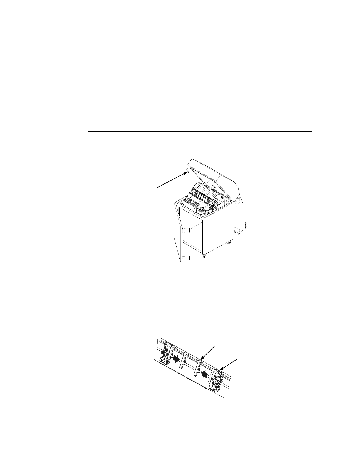
Figure 11. Releasing the Paper Chains
NOTE: If you have the power paper stacker installed, skip this
procedure and go to “Remove The Shipping Restraints
From The Optional Power Stacker” on page 18.
1. Open the cabinet rear door.
2. Cut the tie wraps and release the paper chains from the bags at
the top rear of the printer frame. Remove the tie wraps and
bags.
3. Make sure each chain hangs freely with no kinks or knots.
Tie Wraps (2)
Paper Chains (8)
Bags (2)
Page 16

Set Up The Printer
16
Remove The Tags
Cabinet Models
Figure 12. Removing Tags from the Cabinet Model
NOTE: If you have the power paper stacker installed, skip this
procedure and go to “Remove The Shipping Restraints
From The Optional Power Stacker” on page 18.
1. Remove the tie wrap attached to the passive stacker paper
fence. The tie wrap is marked with a large, red tag.
2. Close the cabinet rear door.
Tie Wrap
Red Tag
Passive Stacker
Paper Fence
Tie Wrap
Red Tag
Passive Stacker
Paper Fence
1000/1500/2000 lpm model
500 lpm model
Page 17

17
Remove The Tags
Pedestal Models
Figure 13. Removing the Tie Wrap from the Pedestal Model
3. Remove the tie wrap attached to the output basket. It is marked
with a large, red tag.
Tie Wrap
Red Tag
Output
Basket
Page 18

Set Up The Printer
18
Attach The Output Basket (Pedestal Models)
Figure 14. Attaching the Output Basket to the Pedestal Model
1. Place the output basket in the holes in the back of the printer.
2. Screw the ground wire attached to the output basket to the
printer.
Remove The Shipping Restraints From
The Optional Power Stacker
This section applies only to printers with the power stacker
installed.
Special packaging protects the power stacker mechanisms from
damage during shipment. This section describes how to remove
the shipping restraints before you operate the printer.
Save the packaging materials. You will need to reinstall them if you
decide to move or ship the printer. To reinstall the packaging
materials, reverse the steps in this section.
p5coutry
$
$
Output
Basket
Screw
Ground Wire
Page 19

19
Remove The Shipping Restraints From The Optional Power Stacker
Figure 15. Removing the Shipping Restraints
1. Open the rear door panel.
2. Remove the seven tie wraps.
3. Raise the paper guide to its highest position by hand.
4. Remove the plastic bags from the paper chains.
Tie Wraps (7)
Paper Guide
Plastic Bags (3)
Page 20

Set Up The Printer
20
Figure 16. Replacing the Paper Tent
5. Remove, unwrap, and replace the paper tent onto the pull-out
drawer.
Paper Tent
Page 21

21
Cabinet Models
Connect The Interface And Power Cables
Cabinet Models
Figure 17. Unpacking Printer Accessories
1. Make sure the printer power switch is set to O (Off).
2. Open the cabinet front door and cut the strap that secures a
box which contains the power cord, printer ribbon, control panel
overlay labels, and documentation.
3. Open the box and remove the power cord, overlays, and
documentation.
Strap
Page 22

Connect The Interface And Power Cables
22
Figure 18. Interface and Power Locations
4. Open the cabinet rear door, and remove the I/O cover from the
selected I/O connector.
5. Locate the cable routing notch in the lower left corner of the
back of the cabinet.
I/O Cover
Cable-Routing
Notches
AC Power
Cable
AC Power
Connection
Power
Switch
I/O Connectors
Page 23

23
Cabinet Models
Figure 19. Routing the I/O Cable
6. Hold the I/O cable below its connector and gently push the
cable through the opening in the grommet.
7. Pull the cable up through the notch until it reaches the I/O plate.
Attach the cable connector to the printer interface connector
previously selected in step 4 of this section.
8. Secure the cable to the printer using the upper and lower
standoffs.
I/O Cable
Grommet
Page 24

Connect The Interface And Power Cables
24
Pedestal Models
Figure 20. Attaching the I/O Cable Connector and AC Power Connector
1. Make sure the printer power switch is set to O (Off).
2. Remove the cover from the I/O connector you have selected.
3. Attach the I/O cable connector to the printer interface
connector.
4. Plug the power cord into the printer AC power connector, then
into the AC power outlet.
Parallel Connector
Auxiliary I/O
Serial Connector
Power Switch
AC Power Connector
Page 25

25
Interface Connections
Interface Connections
Figure 21. Standard Interfaces
NOTE: Centronics is not present on Network-based models.
55auxios
Jul
y
14, 1999
Dataproducts
Standard Adapter
Serial RS-232/RS-422
Auxiliary I/O
Diagnostic
Pedestal Models
Centronics, Ethernet
Centronics
Ethernet
Auxiliary I/O
Serial RS-232/RS-422
Diagnostic
Cabinet Models
Page 26

Connect The Interface And Power Cables
26
Figure 22. Optional Interfaces for the Auxiliary I/O
1. Remove the cover from the I/O connector you have selected.
2. Attach the I/O cable connector to the printer interface
connector.
3. Guide the AC power cable up through the hole in the lower right
back corner of the cabinet (see Figure 18.)
4. Thread the power cable inside the bracket where the gas
spring is attached.
5. Plug the power cable into the printer AC power connector, then
into the AC power outlet.
Network
10/100Base-T
Coax/Twinax
Dataproducts
Long Line
Page 27

27
Attach The Control Panel Overlays
Install Basic Components
The following procedures describe how to attach the printed
overlays to the control panel and install the printer ribbon and
paper.
Attach The Control Panel Overlays
Figure 23.Attaching Control Panel Overlays
1. Choose the overlay labels in the appropriate language.
2. Cabinet models: Open the printer cover, peel the protective
backing off the overlay, and press the overlay into place.
3. Pedestal models: Open the printer cover and insert the
overlay labels by sliding them behind the control panel
assembly in the appropriate place.
P5000 Series Pedestal Models
Control Panel Assembly
Overlay Labels (2)
Overlay Label
All Models
Page 28

Install Basic Components
28
Load The Ribbon
Figure 24. Preparing to Load the Ribbon
1. Open the printer cover.
2. Raise the forms thickness lever as far as it will go.
3. Close the tractor doors.
Tractor Door
Forms Thickness Lever
Page 29

29
Load The Ribbon
Figure 25. Loading the Ribbon
4. Squeeze the right hub latch and place the full spool on the right
hub. Be sure the ribbon feeds off the outside of the spool.
5. Press the spool down until the hub latch snaps into place.
NOTE: The “Clean Hands” ribbon, identified by a long metallic
leader, enables you to install the ribbon without getting ink
on your hands.
Right Hub
Latch
Spool
Page 30

Install Basic Components
30
Figure 26. Threading the Ribbon around the Ribbon Guide
6. Thread the ribbon around the ribbon guide and along the ribbon
path. Be sure to thread the ribbon between the hammer bank
cover and the ribbon mask.
7. Place the empty spool on the left hub.
8. Press the spool down until the hub latch snaps into place.
9. Turn the empty spool by hand to make sure the ribbon tracks
correctly in the ribbon path and ribbon guides.
NOTE: The P5220 printer automatically winds the leader onto the
spool, once the printer is set online and the next print job is
received.
Ribbon Guide
Left Hub
Page 31

31
Load The Paper
Load The Paper
When you start this procedure, verify that the printer cover is open,
the forms thickness lever is raised, and the tractor doors are open.
Figure 27. Aligning the Paper Supply
1. Align the paper supply with the label on the floor. Make sure the
paper pulls freely from the box.
Figure 28. Feeding the Paper Through the Paper Slot
Label
Paper Slot
Paper Slot
Cabinet Models
Pedestal Models
Page 32

Install Basic Components
32
2. Feed the paper up through the paper slot. Hold the paper in
place with one hand (to prevent it from slipping down through
the paper slot) while pulling it through from above with your
other hand.
Figure 29. Loading Paper onto the Left Tractor Sprockets
3. Pull the paper above and behind the ribbon mask, which is a
silver metal strip with a clear plastic edge protector.
4. Load the paper on the left tractor sprockets.
5. Close the tractor door.
Paper
Left Tractor Door
Left Tractor
Lock
Page 33

33
Load The Paper
CAUTION
To avoid damage to the printer caused by printing on the
platen, always position the left tractor unit directly to the left of
the “1” mark on the paper scale.
Figure 30. Using the Paper Scale as a Guide
Paper
Paper Scale
Tractor
Tractor Splined Shaft
Tractor Splined Shaft
Tractor
Paper Scale
P5000 Series Models
P5220 Models
Horizontal
Adjustment
Knob
Page 34

Install Basic Components
34
6. If adjustment is necessary:
a. Unlock the left tractor.
b. Slide the tractor until it is directly to the left of the number
“1” on the paper scale and lock it. You can also use the
paper scale to count columns.
c. Lock the left tractor.
7. For the P5000 Series models:
After both tractors are secured, use the horizontal adjustment
knob to make fine horizontal paper adjustments.
Figure 31. Loading the Paper onto the Right Tractor Sprockets
8. Unlock the right tractor.
9. Load the paper onto the right tractor sprockets.
10. Close the tractor door.
11. Make sure the leading edge of the first sheet of paper is parallel
to the tractor splined shaft. If the paper is misaligned, reload it
onto the tractor sprockets until its edge is parallel to the splined
shaft.
12. Slide the right tractor to remove paper slack or to adjust for
various paper widths.
13. Lock the tractor.
Right Tractor Door
Page 35

35
Load The Paper
Figure 32. Set the Forms Thickness Lever based on the Paper Thickness
14. Lower the forms thickness lever, and set it to match the paper
thickness. (The A-B-C scale corresponds approximately to
1-, 3-, and 6-part paper thickness.)
NOTE: Do not set the forms thickness lever too tightly; excessive
friction can cause paper jams, ribbon jams (with potential
for ribbon damage), smeared ink, or wavy print.
15. For pedestal models with the Quick Access Cover, see Figure
40 on page 42 for paper exiting options. For all other pedestal
models, manually feed the paper through the rear paper exit by
using the vertical position knob.
NOTE: For cabinet models with the power paper stacker installed,
go to “SureStak Power Paper Stacker” on page 36 in the
following section. For all other cabinet models, go to “Set
The Top-of-Form” on page 43.
Forms Thickness Lever
Page 36

Install Optional Components
36
Install Optional Components
The following procedures describe how to set up certain optional
features: the optional SureStak Power Paper Stacker for cabinet
models and the Quick Access Cover for pedestal models.
NOTE: If your printer does not have either of these options, go to
“Set The Top-of-Form” on page 43.
SureStak Power Paper Stacker
This section explains how to set up and use the optional SureStak
Power Paper Stacker. The SureStak Power Paper Stacker
mechanically directs the paper from the printer to the paper stacker.
Power Stacker Component Locations
Familiarize yourself with the names and locations of the
components, shown in Figure 33, before operating the paper
stacker.
Figure 33. Power Stacker Component Locations
Pinch Rollers
Paper Throat
Rear Control
Panel
Wire Paper
Tent
Paddle Shaft
Bearing Bracket
Paper Length
Indicator
Elevator Lift
Handle
Elevator
Disable Switch
Page 37

37
SureStak Power Paper Stacker
Setting Up The Power Stacker
Figure 34. Use the Rear Control Panel to Set Up the Power Stacker
1. Set the power switch to | (On).
2. Using the rear control panel, press ON LINE to take the printer
offline.
3. Grasp the elevator lift handle and press the elevator disable
switch, while raising the elevator to the top of its travel.
$
$
Stacker Up
Stacker
Down
Paper
Advance
Elevator Disable
Switch
Elevator Lift
Handle
Page 38

Install Optional Components
38
Figure 35. Power Stacker Components
4. Make sure the wire paper tent is fitted in the pull out paper tray
in the base of the stacker.
Wire Paper Tent
Paper
Stacker Rails
Page 39

39
SureStak Power Paper Stacker
Figure 36. Setting the Paper Length
5. Set the desired paper length (5-12 inch range), as follows:
Grasping the paddle shaft, push or pull towards the front or the
rear of the printer, setting the desired paper length by aligning
the indicator notch on the bearing bracket with the paper length
indicator.
$
$
Paddle Shaft
Bearing Bracket
Paper Length Indicator
Page 40

Install Optional Components
40
Loading And Starting The Power Stacker
Figure 37. Stacking Sheets of Paper on the Wire Paper Tent
1. Using the rear control panel, press the PAPER ADVANCE key
and hand feed the paper in the paper throat. Continue to
advance the paper until it reaches the wire tent and there is an
excess of 3-5 pages in the stacker. Be certain the paper passes
through the paper stacker throat smoothly.
2. Stack the 3-5 sheets of paper on top of the wire paper tent,
making sure the paper lies with the natural fold on the printer’s
main control panel.
Wire Paper Tent
Page 41

41
SureStak Power Paper Stacker
Figure 38. Returning the Stacker Frame to its Proper Position
3. Press the ON LINE key, from either the front or rear control
panel, to put the printer in the online state. The stacker frame
then returns to its proper position for printing.
4. Check that the paper is still centered between the paper
guides.
5. Close the cabinet rear door.
6. You are now ready to print. Go to “Set The Top-of-Form” on
page 43.
Rear Control
Panel
Page 42

Install Optional Components
42
Quick Access Cover (Pedestal Models)
Figure 39. The Quick Access Cover on the Pedestal Model
Figure 40. Paper Exit Options
If your pedestal model is equipped with the quick access cover, you
may choose how the paper exits the printer. Pushing the lever up
on the quick access cover allows the paper to exit the rear of the
printer similar to a regular pedestal model. Pulling the lever down
allows the paper to exit the top of the printer for demand printing.
Quick Access Cover
Lever
Lever
(Pushed Up)
Lever
(Pulled Down)
Paper Exiting the Rear of Printer Paper Exiting the Top of Printer
Page 43

43
Procedure
Set The Top-of-Form
Every time you load paper, you must tell the printer where the topof-form (TOF) is. This procedure must be performed the first time
paper is introduced into the printer, and every time new paper is
loaded.
Procedure
1. Be sure the forms thickness lever is raised. If the printer is off,
set the power switch to I (On).
2. Press PAPER ADVANCE several times to ensure the paper
feeds properly beyond the tractors and over the lower paper
path. Ensure the paper folds properly in the stacking area.
Figure 41. Raising the Forms Thickness Lever
3. Raise the forms thickness lever as far as it will go. This allows
you to turn the vertical position knob freely to align the top-ofform.
Vertical Position Knob
Forms Thickness Lever
Page 44

Set The Top-of-Form
44
Figure 42. Aligning the First Page with the TOF Indicator
4. Locate the TOF indicator. It is a small tab located on both the
right and left tractor doors.
5. Turn the vertical position knob to align the top of the first page
with the TOF indicator.
NOTE: For best print quality, it is recommended that the top-of-
form be set at least 1/2 inch below the perforation.
TOF Indicator
Perforation
Vertical
Position
Knob
Page 45

45
Procedure
Figure 43. Matching the Forms Thickness Lever to the Paper Thickness
6. Lower the forms thickness lever. Set it to match the paper
thickness. (The A-B-C scale corresponds approximately to
1-, 3-, and 6-part paper thickness.)
NOTE: Do not set the forms thickness lever too tightly; excessive
friction can cause paper jams, ribbon jams with potential for
ribbon damage, smeared ink, or wavy print.
7. Press CLEAR to remove any fault messages (such as “LOAD
PAPER”) from the message display.
8. Press SET TOF. The top-of-form position you have set moves
down to the print position.
9. Press ON LINE to place the printer in online mode.
Forms Thickness Lever
Page 46

Power On The Printer
46
Power On The Printer
When you power on the printer, it executes a self-test. The default
power-up state is online. When the self-test completes and the
software has initialized successfully, the status indicator light turns
on, indicating that the printer is online. The default value of the type
of emulation you have installed appears in the display.
Print A Test Page
As a test, print a configuration by following the instructions below:
Step Press Result Notes
1. Make sure the printer is on. Raise the printer cover.
2.
3. Allows you to make
configuration changes.
4.
5.
6.
ON LINE
OFFLINE
CONFIG. CONTROL
+
ENTER SWITCH
UNLOCKED
OFFLINE
CONFIG. CONTROL
CONFIG. CONTROL
Load Config.
UNTIL
CONFIG. CONTROL
Print Config.
Print Config.
Current*
Page 47

47
Procedure
For More Information
This Quick Setup Guide provides general information for use of
your printer. For detailed information, refer to your User’s Manual,
which is on the CD-ROM.
7. Press until the desired
option displays.
8. The configuration listing
begins to print.
9. Carefully tear off the configuration printout.
10. Locks the ENTER key.
11.
12. Close the printer cover. Store the printout in a safe place. The printer is ready
for operation.
Step Press Result Notes
OR
Print Config.
All
ENTER
OFFLINE
CONFIG. CONTROL
+
ENTER SWITCH
LOCKED
ON LINE
ONLINE
Page 48

For More Information
48
Page 49

Page 50

PRINTRONIX, INC.
14600 Myford Road
P.O. Box 19559
Irvine, CA 92623-9559
Phone: (714) 368-2300
Fax: (714) 368-2600
Customer Solutions Center: (714) 368-2686
P
RINTRONIX
Nederland BV
P.O. Box 163, Nieuweweg 283
NL-6600 AD Wijchen
The Netherlands
Phone: (31) 24 6489489
Fax: (31) 24 6489499
P
RINTRONIX, Schweiz GmbH
42 Changi South Street 1
Changi South Industrial Estate
Singapore 486763
Phone: (65) 6542-0110
Fax (65) 6543-0220
Visit our web site at:
www.printronix.com
174935-001B
'$!& "('
 Loading...