

Page 1
R
Maintenance Manual
P3000 Printer
Page 2

Page 3

P3000 Printer
Maintenance Manual
P/N 111839–001, Rev C
R
Page 4

US and CANADA Radio Interference Note
Note: This device complies with Part 15 of the FCC Rules. Operation is subject to the following two
conditions: (1) this device may not cause harmful interference, and (2) this device must accept any
interference received, including interference that may cause undesired operation.
Properly shielded and grounded cables and connectors must be used in order to meet FCC emission limits.
The manufacturer is not responsible for any radio or television interference caused by using other than
recommended cables and connectors or by unauthorized changes or modifications to this equipment.
Unauthorized changes or modifications could void the user’s authority to operate the equipment.
The
input/output (I/O) cable must be shielded for the printer
to comply with FCC rules and regulations Part 15
governing the radiation limits for Class “A” equipment.
This Class A digital apparatus meets all requirements of the Canadian Interference–Causing Equipment
Regulations.
Cet appareil numérique de la classe A respecte toutes les exigences du Règlement sur le matériel brouilleur
du Canada.
WARNING
This is a Class A product. In a domestic environment this product may cause radio interference in which
case the user may be required to take adequate measures.
Printronix, Inc. makes no representations or warranties of any kind regarding this material, including, but not
limited to, implied warranties of merchantability and fitness for a particular purpose. Printronix, Inc. shall not
be held responsible for errors contained herein or any omissions from this material or for any damages,
whether direct, indirect, incidental or consequential, in connection with the furnishing, distribution,
performance or use of this material. The information in this manual is subject to change without notice.
This document contains proprietary information protected by copyright. No part of this document may be
reproduced, copied, translated or incorporated in any other material in any form or by any means, whether
manual, graphic, electronic, mechanical or otherwise, without the prior written consent of Printronix, Inc.
All rights reserved. Revision C. January 1996.
17500 Cartwright Road, P.O. Box 19559
Irvine, California 92713
Telephone (714) 863–1900 FAX (714) 660–8682
Technical Support (714) 221–2686
COPYRIGHT 1988, 1989, 1996, PRINTRONIX, INC.
Page 5

Table of Contents
Paragraph Title Page
MAINTENANCE O
1-1 Introduction 1-1. . . . . . . . . . . . . . . . . . . . . . . . . . . . . . . . . . . . . . . . . . . . . . . . .
1-2 P
1-3 Operation 1-2. . . . . . . . . . . . . . . . . . . . . . . . . . . . . . . . . . . . . . . . . . . . . . . . . . .
2-1 General 2-1. . . . . . . . . . . . . . . . . . . . . . . . . . . . . . . . . . . . . . . . . . . . . . . . . . . . .
2-2 F
2-3 P
2-4 P
2-5
2-6
2-7 P
3-1 General 3-1. . . . . . . . . . . . . . . . . . . . . . . . . . . . . . . . . . . . . . . . . . . . . . . . . . . . .
3-2 P
3-3 Inspection 3-1. . . . . . . . . . . . . . . . . . . . . . . . . . . . . . . . . . . . . . . . . . . . . . . . . . .
3-4 Cleaning 3-2. . . . . . . . . . . . . . . . . . . . . . . . . . . . . . . . . . . . . . . . . . . . . . . . . . . .
3-5 P
3-6 Lubrication 3-9. . . . . . . . . . . . . . . . . . . . . . . . . . . . . . . . . . . . . . . . . . . . . . . . . .
rinter Description
PRINCIPLES OF OPER
unctional Elements
aper T
ransport 2-1. . . . . . . . . . . . . . . . . . . . . . . . . . . . . . . . . . . . . . . . . . . . . .
rinting Mechanism
Controller PCBA
Mechanism Driver PCBA
ower Supply PCBA
PREVENTIVE MAINTENANCE
reventive Maintenance Checks and Service (PMCS)
aper F
eed Belt T
ension Check
CHAPTER l
VERVIEW
CHAPTER 2
ATION
CHAPTER 3
1-1. . . . . . . . . . . . . . . . . . . . . . . . . . . . . . . . . . . . . . . . . . .
2-1. . . . . . . . . . . . . . . . . . . . . . . . . . . . . . . . . . . . . . . . . .
2-4. . . . . . . . . . . . . . . . . . . . . . . . . . . . . . . . . . . . . . . . . .
2-11. . . . . . . . . . . . . . . . . . . . . . . . . . . . . . . . . . . . . . . . . . . .
2-13. . . . . . . . . . . . . . . . . . . . . . . . . . . . . . . . . . . . .
2-20. . . . . . . . . . . . . . . . . . . . . . . . . . . . . . . . . . . . . . . . .
3-1. . . . . . . . . . . . . .
3-9. . . . . . . . . . . . . . . . . . . . . . . . . . . . . . . . .
CHAPTER 4
TROUBLESHOOTING
4-1 General 4-1. . . . . . . . . . . . . . . . . . . . . . . . . . . . . . . . . . . . . . . . . . . . . . . . . . . . .
4-2 Common Causes of Malfunctions 4-1. . . . . . . . . . . . . . . . . . . . . . . . . . . . . . .
4-3
4-4 F
5-1 Introduction 5-1. . . . . . . . . . . . . . . . . . . . . . . . . . . . . . . . . . . . . . . . . . . . . . . . .
5-2 Tools, T
5-3 P
5-4
5-5
5-6 Bumpers 5-8. . . . . . . . . . . . . . . . . . . . . . . . . . . . . . . . . . . . . . . . . . . . . . . . . . . .
5-7
5-8
Internal T
ault Isolation
aper Scale
Hammer T
Hammer Spring R
Stroke T
Hammer Phasing
esting 4-1. . . . . . . . . . . . . . . . . . . . . . . . . . . . . . . . . . . . . . . . . . . . . .
CORRECTIVE MAINTENANCE
est Equipment, and Supplies
Section II. ALIGNMENTS AND ADJUSTMENTS
ips 5-3. . . . . . . . . . . . . . . . . . . . . . . . . . . . . . . . . . . . . . . . . . . . . . . .
iming 5-10. . . . . . . . . . . . . . . . . . . . . . . . . . . . . . . . . . . . . . . . . . . . . .
CHAPTER 5
Section I. GENER
etensioning 5-6. . . . . . . . . . . . . . . . . . . . . . . . . . . . . . . . . .
AL
4-1. . . . . . . . . . . . . . . . . . . . . . . . . . . . . . . . . . . . . . . . . . . . . . .
5-2. . . . . . . . . . . . . . . . . . . . . . . . . . . . .
5-3. . . . . . . . . . . . . . . . . . . . . . . . . . . . . . . . . . . . . . . . . . . . . . . . . .
5-11. . . . . . . . . . . . . . . . . . . . . . . . . . . . . . . . . . . . . . . . . . . .
iP3000 Maintenance
Page 6

Table of Contents
Paragraph Title Page
5-9 T
5-10 P
5-11
5-12
5-13
5-14
5-15 Cabinet 5-24. . . . . . . . . . . . . . . . . . . . . . . . . . . . . . . . . . . . . . . . . . . . . . . . . . . .
5-16
5-17 Cover 5-28. . . . . . . . . . . . . . . . . . . . . . . . . . . . . . . . . . . . . . . . . . . . . . . . . . . . .
5-18
5-19
5-20
5-21
5-22 P
5-23
5-24 P
5-25
5-26
5-27
5-28
5-29
5-30
5-31 Encoder 5-54. . . . . . . . . . . . . . . . . . . . . . . . . . . . . . . . . . . . . . . . . . . . . . . . . . .
5-32
5-33 Bumper 5-58. . . . . . . . . . . . . . . . . . . . . . . . . . . . . . . . . . . . . . . . . . . . . . . . . . . .
5-34 P
5-35 P
5-36
5-37
5-38 Tractor 5-68. . . . . . . . . . . . . . . . . . . . . . . . . . . . . . . . . . . . . . . . . . . . . . . . . . . .
5-39 P
5-40
5-41
5-42 P
5-43
5-44
5-45
5-46 Fan 5-84. . . . . . . . . . . . . . . . . . . . . . . . . . . . . . . . . . . . . . . . . . . . . . . . . . . . . . .
5-47
5-48 A
5-49 P
iming Belt T
aper Drive Motor Pulley Alignment
Spline Shaft Skew A
Platen Angle A
Platen Gap A
Ribbon Guide Alignment
Control P
Display Control P
Control P
Controller PCBA
Mechanism Driver PCBA
ower Supply PCBA
Shuttle Cover
aper Scale
Motherboard PCBA
I/O Cable Assembly
Shuttle Assembly
Hammer Bank Cable Assembly
Hammer Spring
Hammer Coil
Encoder PCBA
aper F
aper Drive Motor
Spline Shaft
Support Shaft
aper Ironer
Platen
Interlock Cable Assembly
aper Detect Switch
Ribbon Drive Motor
Ribbon Guide
Blower Assembly
Circuit Breaker
C Input Filter
aper F
ension A
djustment 5-17. . . . . . . . . . . . . . . . . . . . . . . . . . . . . . . . . . . . .
djustment 5-20. . . . . . . . . . . . . . . . . . . . . . . . . . . . . . . . . . . . . .
anel 5-26. . . . . . . . . . . . . . . . . . . . . . . . . . . . . . . . . . . . . . . . . . . . . . .
anel Cable 5-32. . . . . . . . . . . . . . . . . . . . . . . . . . . . . . . . . . . . . . . . .
eed T
iming Belt
eed Motor Pulley
djustment 5-12. . . . . . . . . . . . . . . . . . . . . . . . . . . . . . .
djustment 5-16. . . . . . . . . . . . . . . . . . . . . . . . . . . . . . . . .
Section III. REPLA
anel 5-30. . . . . . . . . . . . . . . . . . . . . . . . . . . . . . . . . . . . . . . .
CEMENT
5-14. . . . . . . . . . . . . . . . . . . . . . . . . .
5-22. . . . . . . . . . . . . . . . . . . . . . . . . . . . . . . . . . . . .
5-34. . . . . . . . . . . . . . . . . . . . . . . . . . . . . . . . . . . . . . . . . . . .
5-37. . . . . . . . . . . . . . . . . . . . . . . . . . . . . . . . . . . . .
5-38. . . . . . . . . . . . . . . . . . . . . . . . . . . . . . . . . . . . . . . . .
5-40. . . . . . . . . . . . . . . . . . . . . . . . . . . . . . . . . . . . . . . . . . . . . . .
5-42. . . . . . . . . . . . . . . . . . . . . . . . . . . . . . . . . . . . . . . . . . . . . . . . .
5-42. . . . . . . . . . . . . . . . . . . . . . . . . . . . . . . . . . . . . . . . .
5-44. . . . . . . . . . . . . . . . . . . . . . . . . . . . . . . . . . . . . . . . .
5-46. . . . . . . . . . . . . . . . . . . . . . . . . . . . . . . . . . . . . . . . . . . .
5-48. . . . . . . . . . . . . . . . . . . . . . . . . . . . . . . .
5-50. . . . . . . . . . . . . . . . . . . . . . . . . . . . . . . . . . . . . . . . . . . . .
5-52. . . . . . . . . . . . . . . . . . . . . . . . . . . . . . . . . . . . . . . . . . . . . . .
5-56. . . . . . . . . . . . . . . . . . . . . . . . . . . . . . . . . . . . . . . . . . . . .
5-60. . . . . . . . . . . . . . . . . . . . . . . . . . . . . . . . . . . . . .
5-62. . . . . . . . . . . . . . . . . . . . . . . . . . . . . . . . . . . . . . . . . .
5-64. . . . . . . . . . . . . . . . . . . . . . . . . . . . . . . . . . . . . . . . . . . . . . . .
5-66. . . . . . . . . . . . . . . . . . . . . . . . . . . . . . . . . . . . . . . . . . . . . . .
5-68. . . . . . . . . . . . . . . . . . . . . . . . . . . . . . . . . . . . . . . . . . . . . . . .
5-70. . . . . . . . . . . . . . . . . . . . . . . . . . . . . . . . . . . . . . . . . . . . . . . . . . . . .
5-74. . . . . . . . . . . . . . . . . . . . . . . . . . . . . . . . . . . .
5-76. . . . . . . . . . . . . . . . . . . . . . . . . . . . . . . . . . . . . . . . .
5-78. . . . . . . . . . . . . . . . . . . . . . . . . . . . . . . . . . . . . . . . .
5-80. . . . . . . . . . . . . . . . . . . . . . . . . . . . . . . . . . . . . . . . . . . . . .
5-82. . . . . . . . . . . . . . . . . . . . . . . . . . . . . . . . . . . . . . . . . . . .
5-86. . . . . . . . . . . . . . . . . . . . . . . . . . . . . . . . . . . . . . . . . . . . .
5-88. . . . . . . . . . . . . . . . . . . . . . . . . . . . . . . . . . . . . . . . . . . . .
5-90. . . . . . . . . . . . . . . . . . . . . . . . . . . . . . . . . . . . .
P3000 Maintenanceii
Page 7

Table of Contents
Paragraph Title Page
APPENDICES
Appendix A
Appendix B
Index I-1. . . . . . . . . . . . . . . . . . . . . . . . . . . . . . . . . . . . . . . . . . . . . . . . . . . . . . . . . . . . . . . . . . . . .
Electronic Drawings
P
arts List
A-1. . . . . . . . . . . . . . . . . . . . . . . . . . . . . . . . . . .
B-1. . . . . . . . . . . . . . . . . . . . . . . . . . . . . . . . . . . . . . . . . . . .
List of Tables
Table Title Page
1-1
1-2
1-3
2-1
3-1 P
3-2
4-1 Fault Codes 4-2. . . . . . . . . . . . . . . . . . . . . . . . . . . . . . . . . . . . . . . . . . . . . . . . .
4-2
4-3
External Controls and Indicators
Internal Controls and Indicators
Controls and Indicators for 3287 Option
Dot Matrices vs Speed/Density
reventive Maintenance Checks and Service
Physical Inspection
Supplimental T
Malfunction Sympton Index
ests 4-3. . . . . . . . . . . . . . . . . . . . . . . . . . . . . . . . . . . . . . . . . . . .
1-4. . . . . . . . . . . . . . . . . . . . . . . . . . . . . . . .
1-6. . . . . . . . . . . . . . . . . . . . . . . . . . . . . . . .
1-8. . . . . . . . . . . . . . . . . . . . . . . . .
2-9. . . . . . . . . . . . . . . . . . . . . . . . . . . . . . . . .
3-1. . . . . . . . . . . . . . . . . . . . . .
3-2. . . . . . . . . . . . . . . . . . . . . . . . . . . . . . . . . . . . . . . . . . .
4-4. . . . . . . . . . . . . . . . . . . . . . . . . . . . . . . . . . . .
5-1 R
ecommended T
ools, T
est Equipment, and Supplies
5-2. . . . . . . . . . . . . . .
iiiP3000 Maintenance
Page 8

List of Illustrations
Figure Title Page
1-1 P
1-2
1-3
1-4
2-1 P
2-2 P
2-3 P
2-4
2-5 P
2-6
2-7
2-8 T
2-9
2-10
2-11
2-12
3-1
3-2
3-3
3-4
3-5 P
rinter with P
External Controls and Indicators
Internal Controls and Indicators
Controls and Indicators for 3287 Option
rinter F
aper T
rinting Mechanism
Hammer and Shuttle Arrangement, Cross Section
rint Hammer A
Standard Character F
Character F
ypical Character Dot P
Controller Block Diagram
Mechanism Driver Block Diagram
Hammer Bank L
Ribbon Driver Circuit
Cleaning Interior of Cabinet
Cleaning Hammer Bank Assembly
Cleaning P
Cleaning F
aper F
edestal 1-3. . . . . . . . . . . . . . . . . . . . . . . . . . . . . . . . . . . . . . . . . .
unctional Block Diagram
ransport 2-3. . . . . . . . . . . . . . . . . . . . . . . . . . . . . . . . . . . . . . . . . . . . . .
ction 2-6. . . . . . . . . . . . . . . . . . . . . . . . . . . . . . . . . . . . . . . . .
ormation 2-7. . . . . . . . . . . . . . . . . . . . . . . . . . . . . . . . .
ormation by One Hammer
atterns, By Mode
ogic, Drivers, and W
aper Ironer
an 3-8. . . . . . . . . . . . . . . . . . . . . . . . . . . . . . . . . . . . . . . . . . . . . . . .
eed Belt T
ension Check
aveforms 2-16. . . . . . . . . . . . . . . . . . .
1-5. . . . . . . . . . . . . . . . . . . . . . . . . . . . . . . .
1-7. . . . . . . . . . . . . . . . . . . . . . . . . . . . . . . .
1-9. . . . . . . . . . . . . . . . . . . . . . . . .
2-2. . . . . . . . . . . . . . . . . . . . . . . . . . . . . . .
2-5. . . . . . . . . . . . . . . . . . . . . . . . . . . . . . . . . . . . . . . . . .
2-6. . . . . . . . . . . . . . . . .
2-8. . . . . . . . . . . . . . . . . . . . . . . . . . .
2-10. . . . . . . . . . . . . . . . . . . . .
2-12. . . . . . . . . . . . . . . . . . . . . . . . . . . . . . . . . . . .
2-14. . . . . . . . . . . . . . . . . . . . . . . . . . . . .
2-18. . . . . . . . . . . . . . . . . . . . . . . . . . . . . . . . . . . . . . . .
3-3. . . . . . . . . . . . . . . . . . . . . . . . . . . . . . . . . . .
3-5. . . . . . . . . . . . . . . . . . . . . . . . . . . . . .
3-7. . . . . . . . . . . . . . . . . . . . . . . . . . . . . . . . . . . . . . . .
3-10. . . . . . . . . . . . . . . . . . . . . . . . . . . . . . . .
4-1
4-2
4-3
4-4
4-5
4-6
4-7
4-8
4-9 P
All Indicators Come on and Stay on at P
No Indicators Come on at P
Indicators on Both Control P
Switches or Indicators Operate Improperly on F
Control P
Digital Display Operates Improperly
CHECK Indicator Flashes--Display Shows
FAULT CONDITION P
CHECK Indicator Flashes--Display Shows
FAULT CONDITON PLATEN OPEN 4-16. . . . . . . . . . . . . . . . . . . . . . . . .
CHECK Indicator on Continuously--Display Shows
FAULT CONDITION DCU RAM, FONT PROM or MCU RAM 4-18. .
aper Doesn't F
anel Only
eed at All
ower-up 4-8. . . . . . . . . . . . . . . . . . . . . . . . . . . .
anels Operate Improperly
APER OUT
ower-up 4-7. . . . . . . . . . . . . . . . .
ront
4-11. . . . . . . . . . . .
4-12. . . . . . . . . . . . . . . . . . . . . . . . . . . . . . . . . . . . . . . . . .
4-13. . . . . . . . . . . . . . . . . . . . . . . . . . .
4-14. . . . . . . . . . . . . . . . . . . . . . . . . . .
4-19. . . . . . . . . . . . . . . . . . . . . . . . . . . . . . . . . . . .
P3000 Maintenanceiv
Page 9

List of Illustrations
Figure Title Page
4-10 P
4-11 P
4-12
4-13
4-14
4-15
4-16
4-17
4-18
4-19
4-20
4-21 P
4-22 P
4-23
4-24
4-25
4-26
4-27
4-28 R
4-29
4-30
4-31
4-32
4-33
4-34
4-35
4-36
4-37
4-38
4-39
4-40
4-41
4-42
4-43
aper F
eeds Erratically
aper Drags
Set T
op-of-F
Ribbon Does not Move at All
Ribbon F
Ribbon Does Not R
Ribbon Does Not Change Direction at End
Shuttle Does Not Move at All
Shuttle Jams or Moves too Slowly
Shuttle Moves Erratically
Shuttle Movement P
rinter Does Not P
rinter F
Missing Characters Example
Characters Missing Consistently
Characters Missing R
Missing Dots Example
Consistent Dropout of Dots
andom Dropout of Dots
Characters Light or Smeared Example
Character P
Dots Misplaced
Improper P
Improper P
Improper Horizontal Alignment Example
Improper V
Improper Horizontal or V
Characters Misformed V
Characters Misformed V
Compacted P
Compacted P
Garbled P
Expected Data Stream P
Blower Motor Not Operating
orm Does not Operate
olds Over 4-31. . . . . . . . . . . . . . . . . . . . . . . . . . . . . . . . . . . . . . . . . .
un Smoothly
roduces Knocking Sound
rint at All
ails to P
rint Only When Controlled by Host Computer
andomly 4-50. . . . . . . . . . . . . . . . . . . . . . . . . . . . . . . . .
ositions Light or Smeared (Dragging Hammer)
rint Density Example
rint Density
ertical Alignment Example
ertical Alignment
ertically Example
ertically 4-67. . . . . . . . . . . . . . . . . . . . . . . . . . . . . . .
rint Example
rint 4-69. . . . . . . . . . . . . . . . . . . . . . . . . . . . . . . . . . . . . . . . . . . .
rint and/or Incorrect F
rintout 4-73. . . . . . . . . . . . . . . . . . . . . . . . . . . . . . . .
ont 4-71. . . . . . . . . . . . . . . . . . . . . . . . . . . .
4-22. . . . . . . . . . . . . . . . . . . . . . . . . . . . . . . . . . . . . . .
4-26. . . . . . . . . . . . . . . . . . . . . . . . . . . . . . . . . . . . . . . . . . . . . . . .
4-28. . . . . . . . . . . . . . . . . . . . . . . . . .
4-29. . . . . . . . . . . . . . . . . . . . . . . . . . . . . . . . .
4-32. . . . . . . . . . . . . . . . . . . . . . . . . . . . . . .
4-34. . . . . . . . . . . . . . . . . . . . .
4-36. . . . . . . . . . . . . . . . . . . . . . . . . . . . . . . . .
4-38. . . . . . . . . . . . . . . . . . . . . . . . . . . . . .
4-41. . . . . . . . . . . . . . . . . . . . . . . . . . . . . . . . . . . . .
4-43. . . . . . . . . . . . . . . . . . . .
4-44. . . . . . . . . . . . . . . . . . . . . . . . . . . . . . . . . .
4-45. . . . .
4-46. . . . . . . . . . . . . . . . . . . . . . . . . . . . . . . . . .
4-47. . . . . . . . . . . . . . . . . . . . . . . . . . . . . . .
4-51. . . . . . . . . . . . . . . . . . . . . . . . . . . . . . . . . . . . . . .
4-53. . . . . . . . . . . . . . . . . . . . . . . . . . . . . . . . . . .
4-54. . . . . . . . . . . . . . . . . . . . . . . . . . . . . . . . . . . .
4-57. . . . . . . . . . . . . . . . . . . . . . . . .
4-58. . . . . . . .
4-59. . . . . . . . . . . . . . . . . . . . . . . . . . . . . . . . . . . . . . . . . . . . .
4-61. . . . . . . . . . . . . . . . . . . . . . . . . . . . . . .
4-62. . . . . . . . . . . . . . . . . . . . . . . . . . . . . . . . . . . . . . .
4-63. . . . . . . . . . . . . . . . . . . . . . .
4-64. . . . . . . . . . . . . . . . . . . . . . . . .
4-65. . . . . . . . . . . . . . . . . . . . . .
4-66. . . . . . . . . . . . . . . . . . . . . . .
4-68. . . . . . . . . . . . . . . . . . . . . . . . . . . . . . . . . . . .
4-74. . . . . . . . . . . . . . . . . . . . . . . . . . . . . . . . .
5-1 P
5-2
5-3
5-4
aper Scale A
Hammer T
Hammer Spring R
Bumper A
djustment 5-4. . . . . . . . . . . . . . . . . . . . . . . . . . . . . . . . . . . . . . .
ip Alignment
djustment 5-9. . . . . . . . . . . . . . . . . . . . . . . . . . . . . . . . . . . . . . . . . .
5-5. . . . . . . . . . . . . . . . . . . . . . . . . . . . . . . . . . . . . . .
etensioning 5-7. . . . . . . . . . . . . . . . . . . . . . . . . . . . . . . . . .
vP3000 Maintenance
Page 10

List of Illustrations
Figure Title Page
5-5 T
5-6 P
5-7
5-8
5-9
5-10
5-11
5-12
5-13 Cover Removal/Installation 5-29. . . . . . . . . . . . . . . . . . . . . . . . . . . . . . . . . . .
5-14
5-15
5-16
5-17
5-18 P
5-19
5-20
5-21 I/O Cable Removal/Installation 5-45. . . . . . . . . . . . . . . . . . . . . . . . . . . . . . . .
5-22
5-23
5-24
5-25
5-26
5-27
5-28
5-29 P
5-30 P
5-31
5-32
5-33 P
5-34
5-35
5-36 P
5-37
5-38
5-39
5-40 F
5-41
5-42 A
5-43 P
iming Belt A
aper Drive Motor Pulley Alignment
Spline Shaft Skew A
Platen Angle A
Platen Gap A
Ribbon Guide Alignment
Cabinet R
Control P
Display Control P
Control P
Controller and Mechanism Driver R
Controller PROM L
ower Supply PCBA R
Shuttle Cover and P
Motherboard PCBA R
Shuttle Assembly R
Hammer Bank Cable Assembly R
Hammer Spring R
Hammer Coil R
Encoder R
Encoder PCBA R
Bumper R
aper F
aper Drive Motor R
Spline Shaft R
Support Shaft R
aper Ironer R
Platen R
Interlock Cable Assembly R
aper Detect Switch R
Ribbon Drive Motor R
Ribbon Guide R
Blower Assembly R
an R
emoval/Installation 5-85. . . . . . . . . . . . . . . . . . . . . . . . . . . . . . . . . . . . .
Circuit Breaker R
C Input Filter R
aper F
djustment 5-13. . . . . . . . . . . . . . . . . . . . . . . . . . . . . . . . . . . . . .
djustment 5-16. . . . . . . . . . . . . . . . . . . . . . . . . . . . . . . . .
djustment 5-18. . . . . . . . . . . . . . . . . . . . . . . . . . . . . . . . . . . . .
djustment 5-21. . . . . . . . . . . . . . . . . . . . . . . . . . . . . . . . . . . . . .
emoval/Installation 5-25. . . . . . . . . . . . . . . . . . . . . . . . . . . . . . . . .
anel R
emoval/Installation 5-27. . . . . . . . . . . . . . . . . . . . . . . . . . . .
anel R
emoval/Installation 5-31. . . . . . . . . . . . . . . . . . . . .
anel Cable Removal/Installation 5-33. . . . . . . . . . . . . . . . . . . . . . .
emoval/Installation 5-35. . . . . . . . . . .
ocations 5-36. . . . . . . . . . . . . . . . . . . . . . . . . . . . . . . . . .
emoval/Installation 5-39. . . . . . . . . . . . . . . . . . . . . . .
aper Scale R
emoval/Installation 5-43. . . . . . . . . . . . . . . . . . . . . . .
emoval/Installation 5-47. . . . . . . . . . . . . . . . . . . . . . . . .
emoval/Installation 5-51. . . . . . . . . . . . . . . . . . . . . . . . . .
emoval/Installation 5-53. . . . . . . . . . . . . . . . . . . . . . . . . . . .
emoval/Installation 5-55. . . . . . . . . . . . . . . . . . . . . . . . . . . . . . . . .
emoval/Installation 5-57. . . . . . . . . . . . . . . . . . . . . . . . . . .
emoval/Installation 5-59. . . . . . . . . . . . . . . . . . . . . . . . . . . . . . . . .
eed T
iming Belt R
emoval/Installation 5-63. . . . . . . . . . . . . . . . . . . . . . . .
emoval/Installation 5-65. . . . . . . . . . . . . . . . . . . . . . . . . . . . . .
emoval/Installation 5-67. . . . . . . . . . . . . . . . . . . . . . . . . . . .
emoval/Installation 5-69. . . . . . . . . . . . . . . . . . . . . . . . . . . . .
emoval/Installation 5-71. . . . . . . . . . . . . . . . . . . . . . . . . . . . . . . . . . .
emoval/Installation 5-77. . . . . . . . . . . . . . . . . . . . . . .
emoval/Installation 5-79. . . . . . . . . . . . . . . . . . . . . .
emoval/Installation 5-81. . . . . . . . . . . . . . . . . . . . . . . . . . . .
emoval/Installation 5-83. . . . . . . . . . . . . . . . . . . . . . . . .
emoval/Installation 5-87. . . . . . . . . . . . . . . . . . . . . . . . . . .
emoval/Installation 5-89. . . . . . . . . . . . . . . . . . . . . . . . . . .
eed Motor Pulley R
emoval/Installation 5-41. . . . . . . . . . . . . .
emoval/Installation 5-49. . . . . . . . . . . . .
emoval/Installation 5-61. . . . . . . . . . . . . . . . . . . .
emoval/Installation 5-75. . . . . . . . . . . . . . . . . .
emoval/Installation 5-91. . . . . . . . . . . . . . . . . . .
5-15. . . . . . . . . . . . . . . . . . . . . . . . . . .
5-23. . . . . . . . . . . . . . . . . . . . . . . . . . . . . . . . . . . . .
P3000 Maintenancevi
Page 11

ABOUT THIS MANUAL
This
manual has been organized and written to make it easy to use. The following information will
help
you use this P3000 Maintenance Manual.
What This Manual Contains
This
manual contains the following information. Consult your table of contents to locate this infor
mation.
Ć
Introduction -
P
rovides brief printer description.
Principles of Operation - Describes functional operation of printer through the use of
block
diagrams and associated text.
Preventive
operation.
Troubleshooting
common
Maintenance
- Presents fault isolation procedures required to determine the source
malfunctions.
-
Lists
detailed procedures required to maintain normal printer
of
Corrective Maintenance - Presents procedures for printer adjustment and alignment
replacement of faulty hardware.
and
Electronic Drawings - Electronic drawings and schematics required for field mainteĆ
nance
are included here.
Parts List -
A parts lists, cross referenced to Chapter 5, Section III, is included here.
Controls and Indicators
Throughout
printer, with all capital letters. Controls and indicators that do not have labeled names are given
functional names that are printed with the first letter of each word capitalized. For example, the
POWER switch has two settings, ON and OFF. The Forms Thickness Adjustment Lever is operĆ
by raising and lowering.
ated
this manual, in text, controls and
indicators are printed exactly as they appear on the
Warnings, Cautions, and Notes
In this manual, extra information is given under the headings WARNING, CAUTION, AND
NOTE.
information about conditions that could lead to injury. Cautions provide information about condi
tions that could lead to equipment damage. Both warnings and cautions are printed in bold type.
Notes
They are set off from the text around
provide extra information and are printed in
them and appear in special typefaces. W
italics.
arnings give
What This Manual Does Not Contain
Detailed,
in
the maintenance manual.
specific information which appears in the User's R
eference Manual will not be repeated
viiP3000 Maintenance
Ć
Page 12

P3000 Maintenanceviii
Page 13

CHAPTER l
MAINTENANCE OVERVIEW
1-1. Introduction
This
manual contains information required to maintain and repair the
rinter (hereafter referred to as the P3000 Series, or simply, the printer).
P
The following documents provide detailed information which supplements this manual.
a.
P3000 P
Contains instructions for unpacking, installing, and operating the printer.
b.
P3000 P
Describes functions and applications available for the P3000 P
rinter Operator's Guide, P/N 111837-001.
rinter User's R
eference Manual, P/N 111838-001.
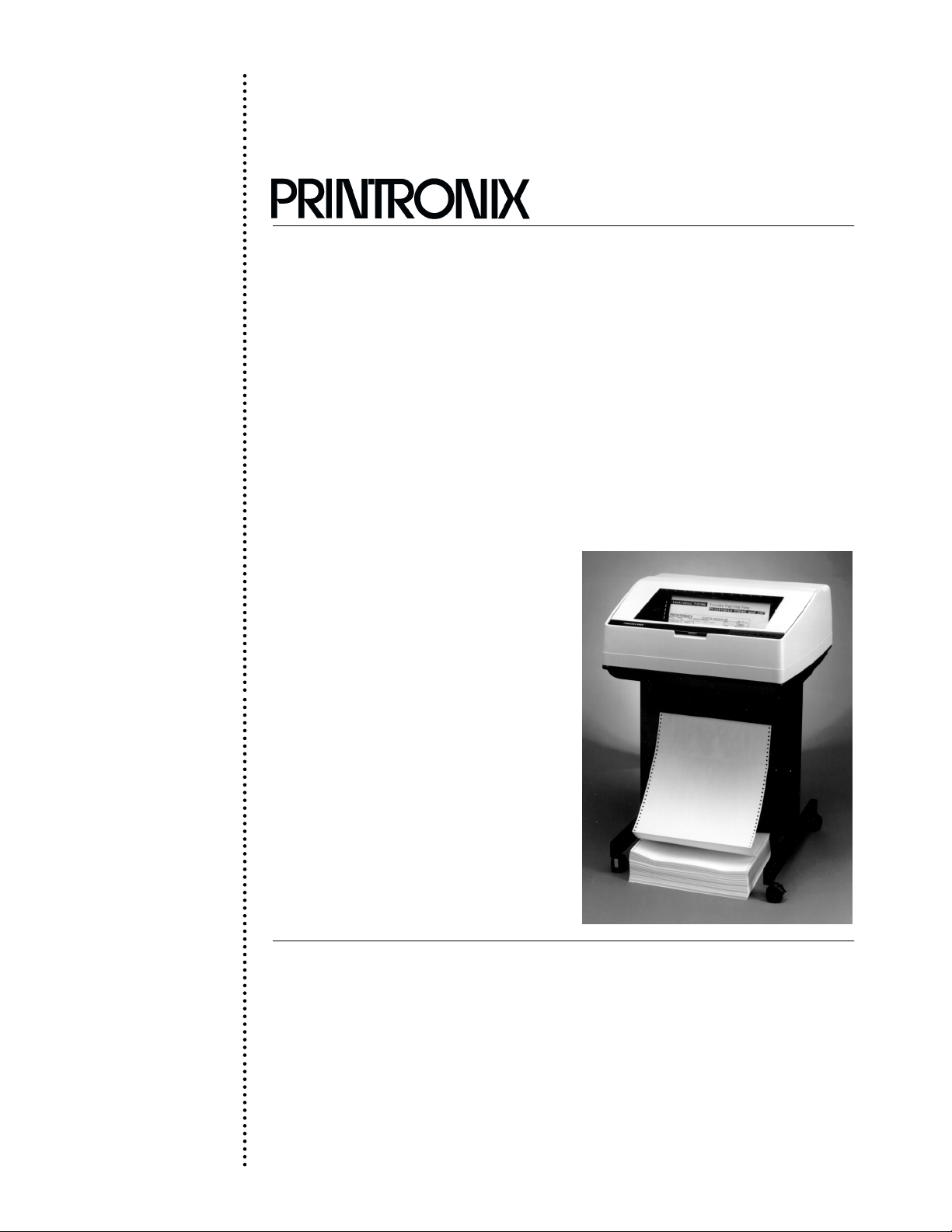
1-2. Printer Description (Figure 1-1)
Printronix P3040
rinter.
a. General
The Printronix
to
produce labels and characters, as well as the standard data processing and compressed
print
character lines and graphics at various densities.
b.
Standard F
l. Configurable
trol
2.
Multi-application character printing
3.
Graphics plotting
4.
Dynamic font selection:
5.
Double high characters
P3000 Series P
eatures
for P
code protocols
(a)
Selectable pitch - expanded, normal, and compressed
(b)
Shadow printing
(c)
Bold printing
(d) A
uto underlining
(e)
Superscripts and subscripts
rinter is a multi-purpose, dot matrix line printer designed
rintronix P Series matrix line printer or serial matrix printer con
Ć
6.
Selectable forms length
7.
Nonvolatile electronic vertical formatting
8. R
esident international character sets
1-1P3000 Maintenance Overview
Page 14

1-2. Printer Description-continued
b. Standard Features-continued
ă9.
Self-test and diagnostics
10. T
est pattern printing
11.
Configuration printout
12.
Datastream HEX code printout
13. R
esident serial and parallel interfaces
14.
Selectable alternate horizontal and vertical dot densities
15.
Configurable for 13.2 or 13.6 inch print width
c. Optional Features
ă1.
Intelligent Graphics P
(a) F
orms generation
(b)
Bar code printing
(c)
Expanded character printing
(d) R
everse image printing
(e) R
otated character printing
(f) L
ogo generation
ă2.
Optional character sets
rocessor (IGP)
ă3.
IBM interfaces
Ribbon fault detector
ă4.
1-3. Operation
a. Operating Procedures
For detailed operating instructions refer to P3000 Printer Operator's Guide, P/N
111837-001.
b. Controls and Indicators
NOTE:
functions. For a detailed discussion, refer to the User's R
optional controls and indicators refer to the PI 3287 User's R
(P/N 108174-001).
1. External
Figure
Internal Controls and
2.
Figure
(a) 3282/3287
(b) 5225/5224
The following tables contain a brief
Controls and Indicators. External controls and indicators
1-2 and described in T
Indicators. Internal controls and indicators are illustrated in
1-3 and described in T
able 1-1.
able 1-2.
summary of control and indicator
eference Manual. F
or
eference Manual
are illustrated in
3. Controls and Indicators for Options. Printers configured to emulate an IBM 3287
will have external controls and indicators as shown in Figure 1-4 and described in
Table 1-3.
P3000 Maintenance Overview1-2
Page 15
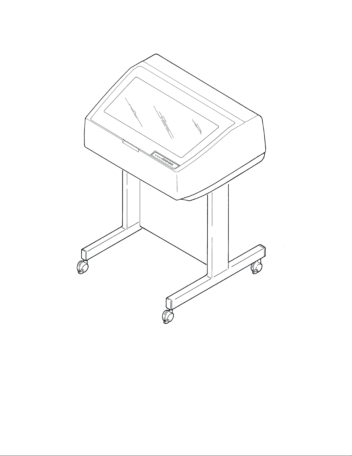
Figure 1-1. P
rinter with P
edestal
1-3P3000 Maintenance Overview
Page 16
Table 1-1. External Controls and Indicators
Key
(Fig 1-2) Control or Indicator Function
1
2
3
4
5
ON/OFF
ON LINE
switch
ON LINE
indicator
CLEAR
switch
CHECK
indicator
6
7
8
6/8LPI
switch
8LPI
indicator
PAPER ADV
switch
Applies and removes ac power to printer
Sets printer online or offline.
Illuminates steadily to indicate printer online
(ready for computer messages).
Flashes to indicate printer offline (not ready
to accept messages).
Resets check circuitry. Used to clear check
indicators after corrective action.
Illuminates to indicate printer problem. Steady
light indicates service is required. Flashing light
indicates operator correctable problem. Lighting
of indicator is accompanied by display of message
on internal display panel (see Table 4-1)
Selects line spacing of six lpi or eight lpi.
Illuminates when alternate lpi selected
Moves paper one line when pressed momentarily.
Moves paper to top of form when pressed for more
than 0.5 second.
NOTE:
Top of form must be reset each time new paper
is loaded (see operator's guide).
9
VFU
indicator
Illuminates when EVFU is loaded.
P3000 Maintenance Overview1-4
Page 17
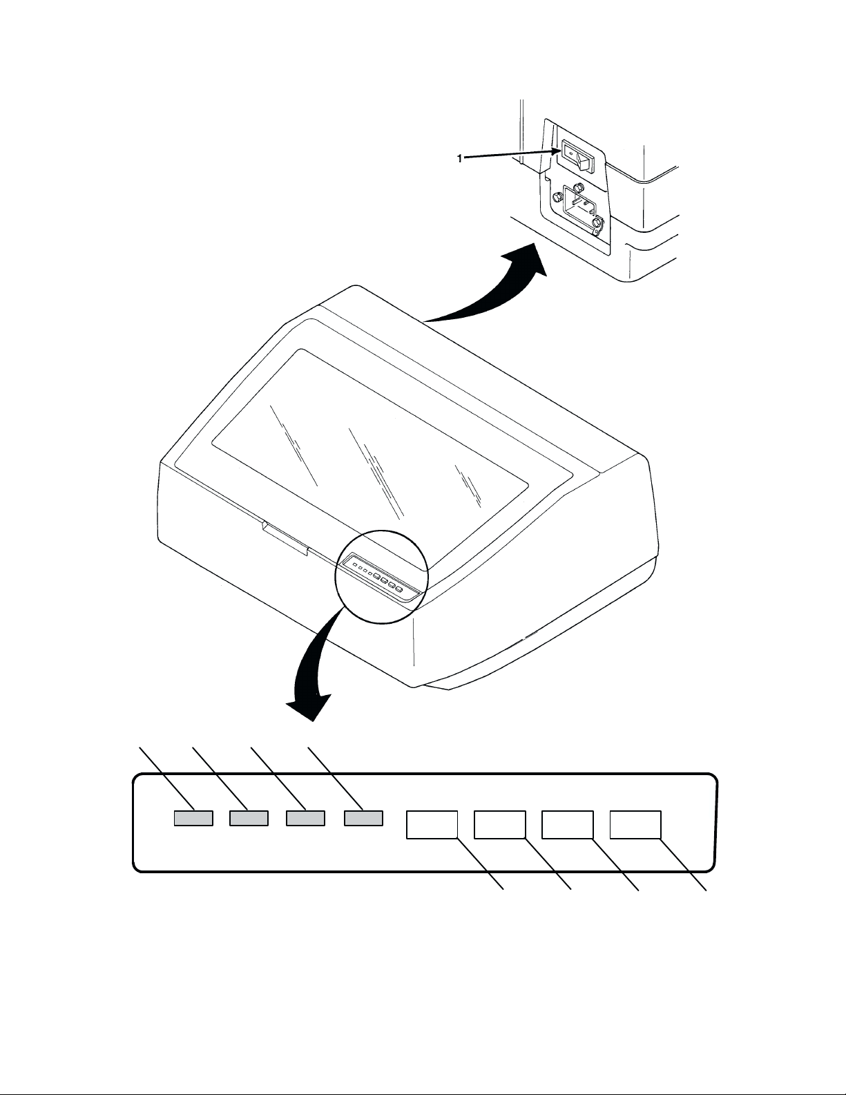
357 9
ON LINE CHECK 8 LPI VFU
Figure 1-2. External Controls and Indicators
ON LINE
CLEAR
6/8 LPI PAPER ADV
2468
1-5P3000 Maintenance Overview
Page 18
Table 1-2. Internal Controls and Indicators
: The following electronic controls function only when the printer is of
NOTE
fline.
Key
(Fig 1-3) Control or Indicator Function
ELECTRONIC
1
2
3
4
5
6
7
Display
Panel
UP
switch
NEXT
switch
R/S
switch
F/L
switch
MODE
switch
ENTER
switch
Displays message for print mode, form length,
fault conditions, test patterns, or configuration options.
For details, refer to User's Reference Manual.
Steps display up to next menu
Used in conjunction with PREV switch to display individual configuration parameters and the current values
from within various menus.
Starts or stops certain printer functions.
Used to select form length.
Selects type of character print or density of graphic plot.
F
or details on how to select mode, refer to Operator's
Guide.
Used to enter a displayed value into memory.
Ć
8
9
MECHANICAL
10
11
12
13
14 Forms Thickness
15
PREV
switch
DOWN
switch
Tractors
Vertical Alignment
Knob (Spline Shaft
Knob)
Forms Thickness
(Platen) Lever
Top of Form
Pointer (indicator
on tractor doors)
Indicator
Horizontal Vernier
Adjustment Knob
Used in conjunction with NEXT switch to display individual configuration parameters and the current values
from within various menus.
Steps display down to next menu.
Provide horizontal positioning of forms.
Manually advances forms.
Opens paper path for insertion/removal of paper.
Adjusts platen opening to allow for paper thickness
A
or multiple copies.
Provides reference when setting top of form after
P
reloading paper.
Indicates setting of platen lever.
Provides fine horizontal positioning when tractors are
locked.
P3000 Maintenance Overview1-6
Page 19
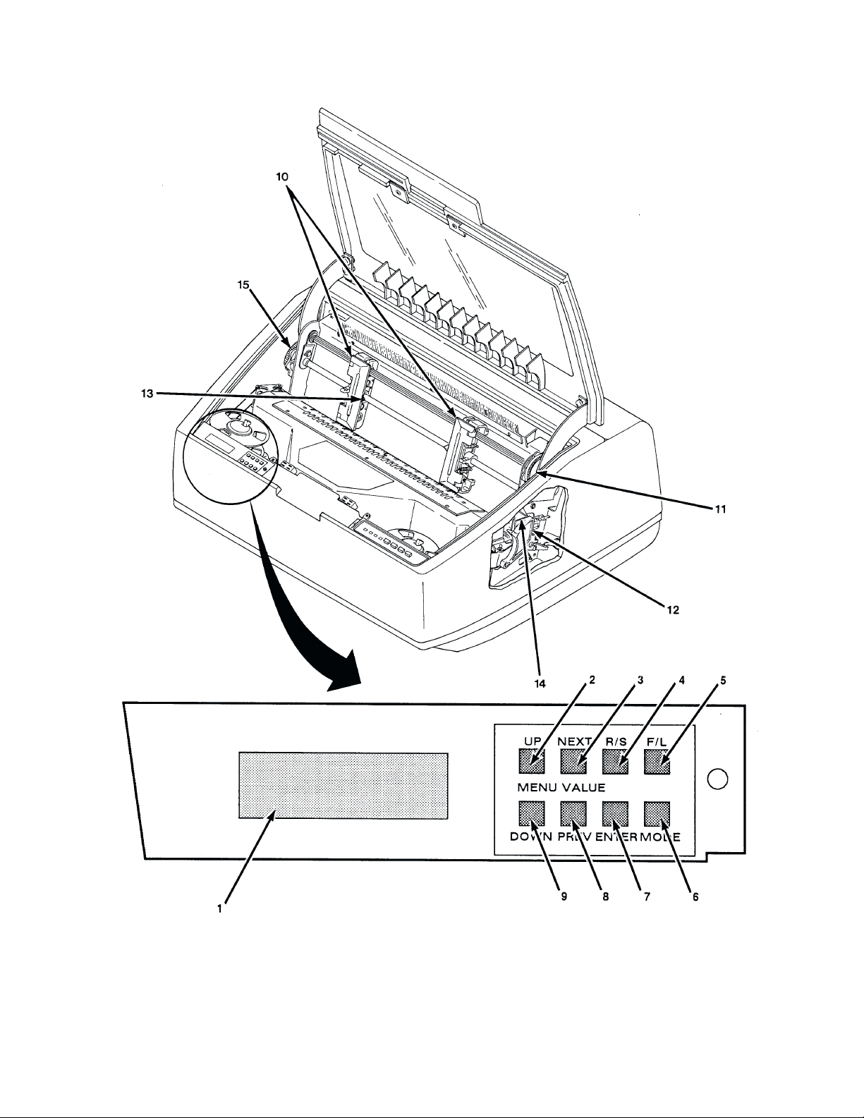
Figure 1-3. Internal Controls and Indicators
1-7P3000 Maintenance Overview
Page 20
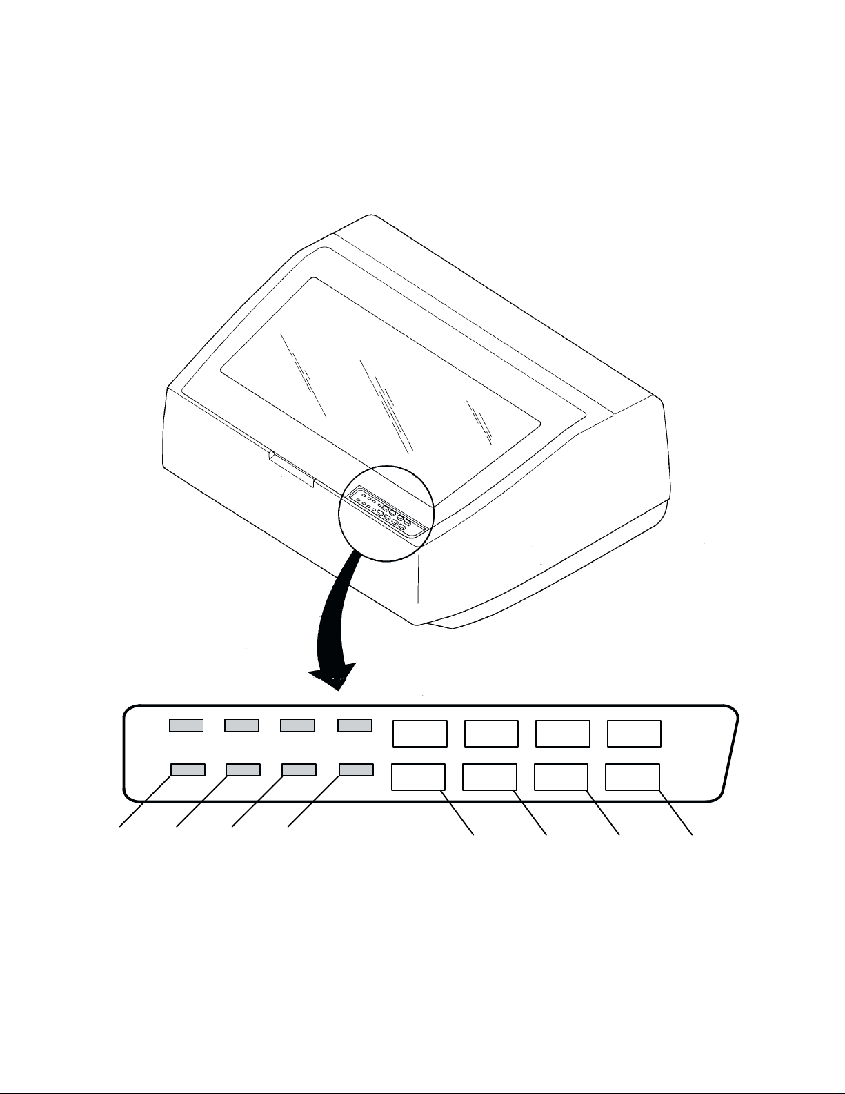
Table 1-3. Controls and Indicators for 3287 Option
NOTE:
panel
Key
(Fig 1-4) Control or Indicator Function
ELECTRONIC
1
2
3
4
Only those controls and indicators
(F
igure 1-3) are discussed below
ENABLE/HOLD
switch
HOLD
indicator
REPRINT/PA1
switch
CANCEL/PA2
switch
Places printer in hold print mode following completion
of line being printed. When pressed a second time, en
ables normal operation.
Lights to indicate printer is in hold print mode.
Causes reprint of all data in interface buffer in nonSCS modes. In SCS modes, sends intervention re
quired message to host processor. A
print mode.
When used in conjunction with AL
causes program attention signal to be sent to host proc
essor.
No effect in non-SCS modes. In SCS modes, causes
printing to stop and SCS print data to be cleared from
buffer. A
ctive only in hold print mode.
that are not present on the standard
.
Ć
Ć
ctive only in hold
T MODE switch,
Ć
5
6
7
8
ALT MODE
switch
READY
indicator
ERROR
indicator
ALT
indicator
Causes alternate switch functions P
come active. A
second time deactivates P
Lights to show that printer is ready to print (not in
hold print mode).
Indicates error condition exists.
Indicates alternate mode selected (P
ctive only in hold print mode. P
A1 and P
A1 and P
A2.
A1 and P
A2 to be-
ressing a
A2 active).
P3000 Maintenance Overview1-8
Page 21
ON LINE CHECK 8 LPI VFU
ENABLE/HOLD 6/8 LPI PAPER ADV
CLEAR
PA1
PA2
ALT MODE
HOLD READY ERROR ALT
2
67 8
REPRINT
1
CANCEL
345
Figure 1-4. Controls and Indicators for 3287 Option
1-9P3000 Maintenance Overview
Page 22

P3000 Maintenance Overview1-10
Page 23

CHAPTER 2
PRINCIPLES OF OPERATION
2-1. General
This chapter presents the principles of operation for the Printronix P3000 Series Line
Printer.
ing field maintenance. R
Theory is presented at the functional block diagram level as an aid for perform
efer to Appendix B for detailed schematic diagrams.
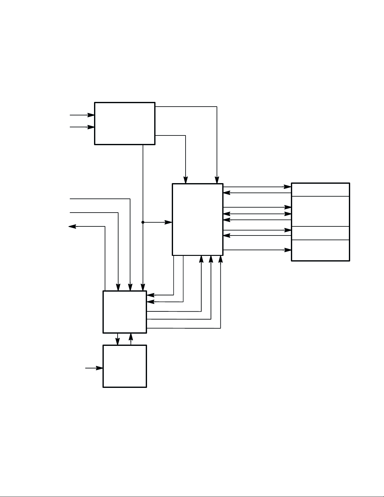
2-2. Functional Elements (Figure 2-1)
Ć
Functional
a. P
b. Printing Mechanism
c.
d.
e. P
elements of the printer consist of the following:
aper T
ransport
Controller PCBA
Mechanism Driver PCBA
ower Supply PCBA
2-3. Paper Transport (Figure 2-2)
The paper transport accepts one to six part, continuous fan folded, edge perforated paĆ
per (or forms) from three to 16-inches wide. The spline shaft knob is used to manually
advance the paper supply vertically. Horizontal positioning of the paper is provided by
tractors which can be adjusted laterally along the spline and support shafts and by a
two
horizontal adjustment knob. When properly positioned, each tractor is then locked in
place. Each tractor provides five
tractors
nals
are belt driven by the paper drive motor. The paper drive motor is
from the two paper feed sections of the mechanism driver PCBA.
pin engagement of paper perforation. During printing,
driven by sig
Ć
2-1P3000 Principles of Operation
Page 24
+30V
AC
POWER
IN
TO/FROM
HOST
COMPUTER
DATA
CONTROL
STATUS
POWER SUPPLY
PCBA
CONTROLLER
PCBA
-16V
+5V
+12 V
-12 V
CONTROL
TIMING
SERIAL DATA
MECHANISM
DRIVER
PCBA
PAPER FEED
PLATEN OPEN/
INTERLOCK
HAMMER CONTROL
SHUTTLE CONTROL
SHUTTLE STALL
RIBBON CONTROL
RIBBON FAULT
BLOWER CONTROL
PRINT MECHANISM
PAPER TRANSPORT
HAMMERBANK/
SHUTTLE
RIBBON
TRANSPORT
BLOWER MOTOR
+5V
OPERATOR
CONTROLS
AND
INDICATORS
Figure 2-1.
P
rinter F
unctional Block Diagram
P3000 Principles of Operation2-2
Page 25
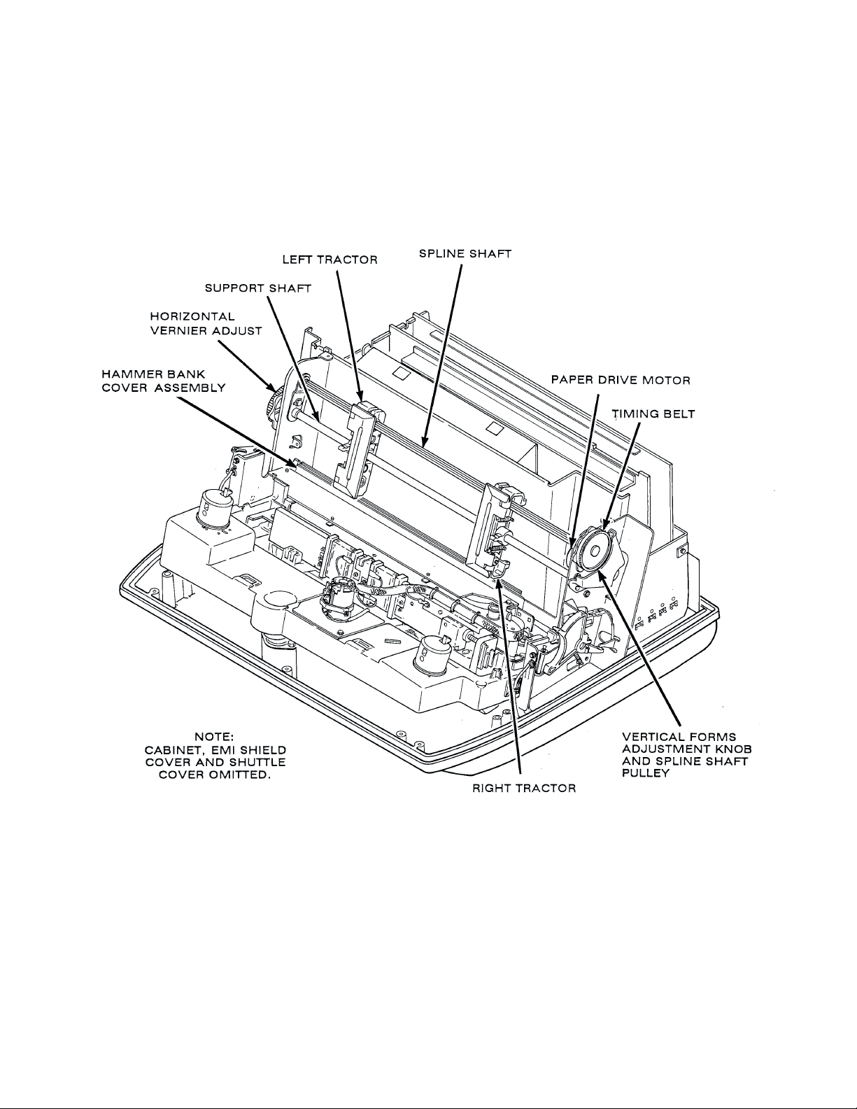
Figure 2-2. P
aper T
ransport
2-3P3000 Principles of Operation
Page 26

2-4. Printing Mechanism (Figure 2-3)
The
printing mechanism consists of the shuttle assembly on which the
sembly is mounted, and the ribbon transport.
a. Shuttle Assembly
The
shuttle assembly consists of the linear motor assembly, two bumper assemblies, two
drum assemblies, the hammer bank assembly, hammer bank cable assembly, encoder
and a linear
PCBA,
and
sweeps the hammer
each hammer. The bumpers rebound the hammer bank assembly's inertial energy
the
shuttle reaches either end of its travel and reverses direction. The drums, in conjunc
tion with a stainless steel band, provide a bearing action to the hammer bank assembly,
allowing it to move with low friction. The optical linear encoder produces timing pulses
that are used to determine hammer bank assembly position and speed to synchronize
printing.
Hammer Bank Assembly
b.
Printing is done by a row of 34 print hammers mounted on the hammer bank assembly.
Each hammer consists of a stiff leaf spring with a small, cylindrical tip on one end. It is
securely on the hammer bank by a screw passing through its other end. A permanent
held
magnet running the full length of the hammer bank and acting through individual pole
holds all 34 hammer springs in the retracted (tensioned) state.
pins
encoder. The linear motor is driven by the mechanism driver PCBA
bank assembly laterally across the 0.4-inch distance traveled by
hammer bank as
when
Ć
Ć
Each print hammer has associated with it a normally deenergized electromagnetic coil
mounted
end of the hammer spring keeping it under tension. When hammer driver logic deterĆ
mines
the resulting magnetic field opposes the field of the permanent magnet, releasing the
hammer
the
During flight time, the coil is deenergized. As the hammer rebounds after striking, the
permanent
In correspondence (NLQ) and data processing (DP) modes, a line of characters is creĆ
ated
in a single scan as the shuttle moves from one side to the other through the character
columns
Figure 2-7 shows the order in which a single character is formed by a single print hamĆ
mer.
on the pole pin (Figure 2-4).
that the hammer is to print a dot, a current pulse energizes the coil. The polarity of
which allows it to impact the ribbon and paper (Figure 2-5) and leave a dot on
paper.
magnet recaptures the hammer and holds it ready for the next stroke.
by a scanning pattern (Figure 2-6). All dots in any row of the dot
(spaces).
The end of this pin magnetically attracts the free
matrix are printed
P3000 Principles of Operation2-4
Page 27
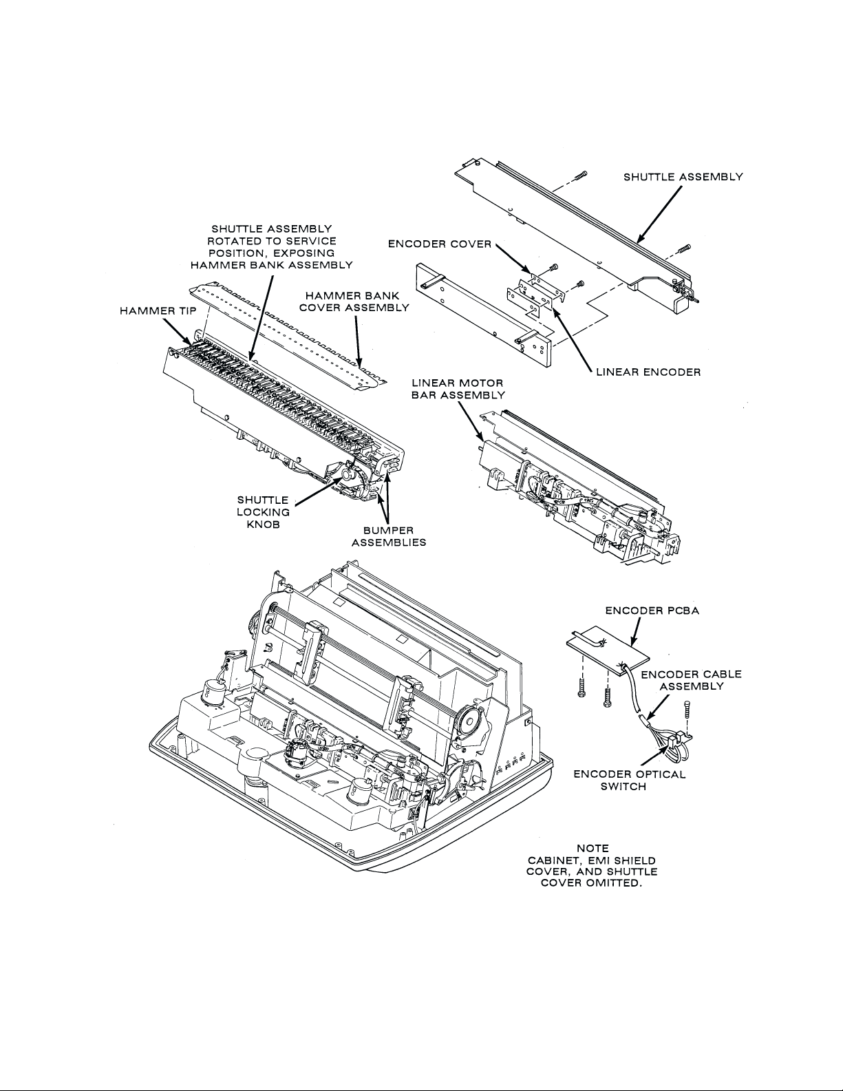
Figure 2-3. Printing Mechanism
2-5P3000 Principles of Operation
Page 28
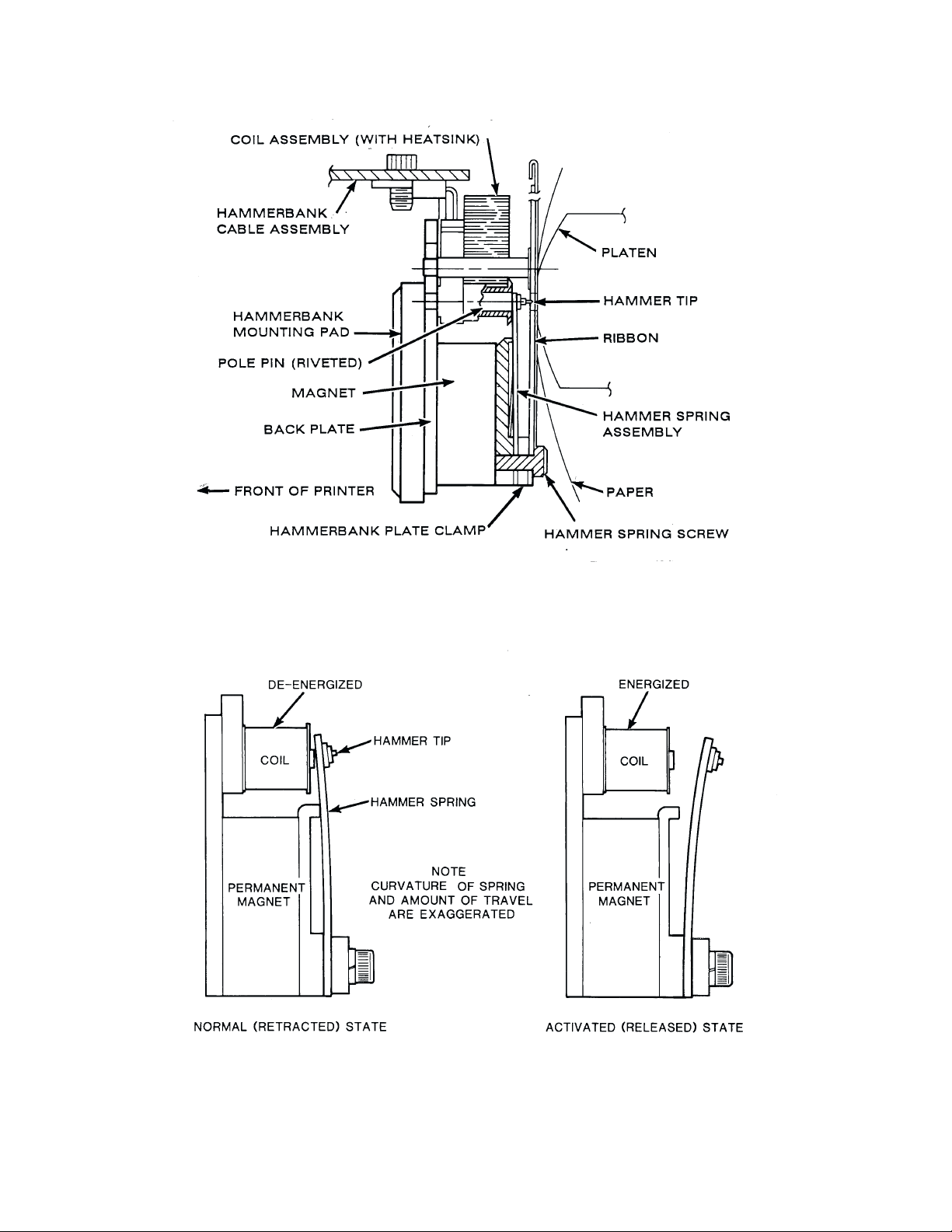
Figure 2-4. Hammer and Shuttle Arrangement, Cross Section
Figure 2-5. P
rint Hammer Action
P3000 Principles of Operation2-6
Page 29
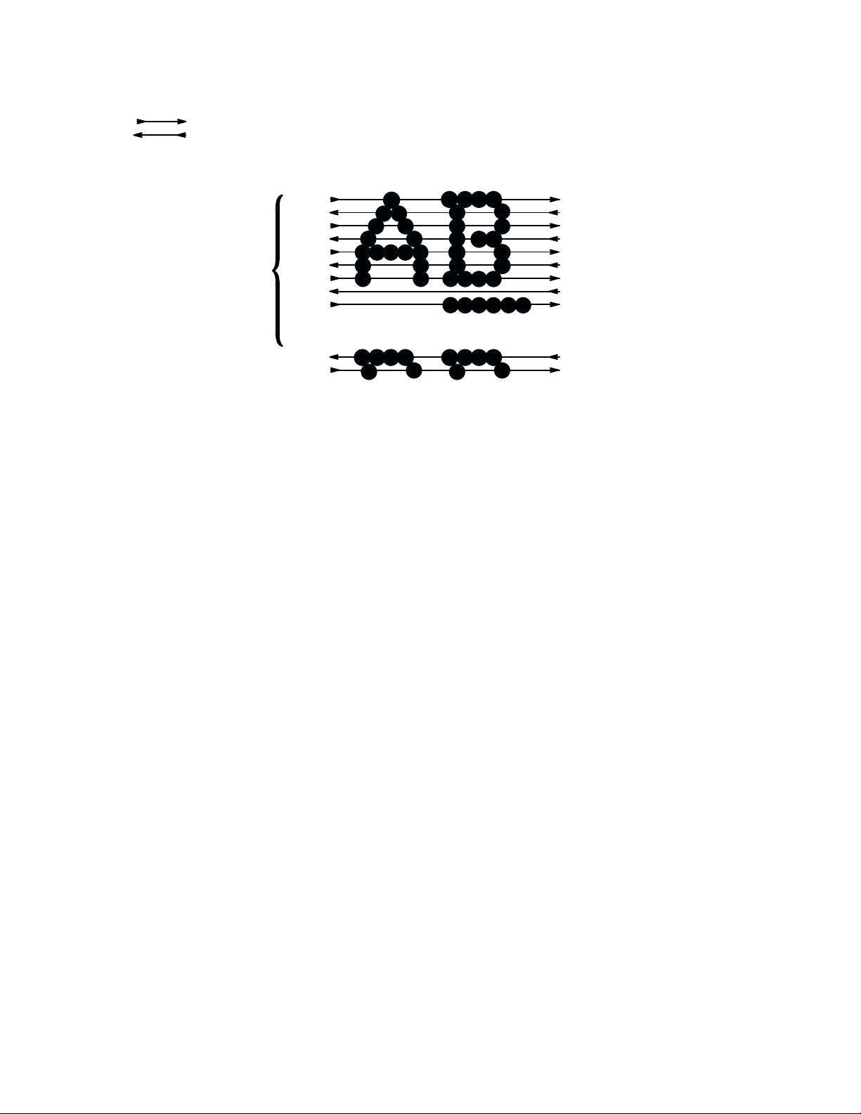
INDICATES DIRECTION OF SHUTTLE MOVEMENT
DOT
ROW START
PAPER
ADVANCES
1
2
3
ONE
CHARACTER
ROW
10
11
12
4
5
6
7
8
*
9
**
SPACE
0
PAPER
FEED
PAPER
ADVANCES
1
2
USED FOR LOWERCASE DESCENDER ONLY
*
USED FOR UNDERLINE AND LOWERCASE DESCENDER
**
NOTE: P3000 SHUTTLE SWEEPS THROUGH FOUR (IN 10 CPI) CHARACTER POSITIONS
Figure 2-6. Standard Character F
ormation
2-7P3000 Principles of Operation
Page 30
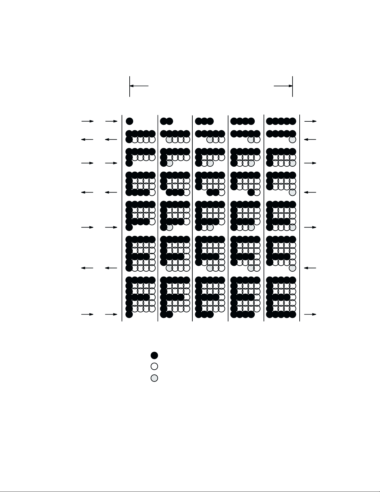
SUCCESSIVE HAMMER STROKES PER SCAN
SHUTTLE
SCAN
1
2
3
4
5
6
7
DOT
ROW
1
1
2
1
2
3
1
2
3
4
1
2
3
4
5
1
2
3
4
5
6
1
2
3
4
5
6
7
113135135713579
******
EVEN COLUMN DOT CENTERS WITHIN THE PRINTED CHARACTER
*
AREA AND CHARACTER SPACE HAMMER POSITIONS ARE NOT
ILLUSTRATED IN THIS DIAGRAM.
NOTE: = DOT
= NO DOT WHERE HAMMER HAS BEEN
= HAMMER POSITION
Figure 2-7. Character Formation by One Hammer
P3000 Principles of Operation2-8
Page 31

2-4. Printing Mechanism-continued
The
shuttle moves in alternate directions as it prints each successive
ters are formed by various dot matrices (Figure 2-8) according to the selected print
as shown in T
mode
able 2-1.
Table 2-1. Dot Matrices vs Speed/Density
row of dots. Charac
Ć
Print Mode
Correspondence (NLQ)
Data Processing
High Speed
In
the correspondence (NLQ) mode, for example, lower case
rows
of a 13 by 12 dot matrix. Seven overlapping dots are printed in
on
13 vertical centers for accurate character rendition.
The
dot printing process continues for the number
selected
advances the paper to the top dot row of the next character line to be printed. During
line
time,
c.
The
the
when
print mode. When an entire character line has been printed, the paper transport
advance, the hammer bank assembly continues the right/left sweeping motion; at this
however, the print hammers are disabled from printing.
Ribbon Transport
printer ribbon advances continuously on spool hubs. Ribbon motors are driven while
hammer bank assembly is running and stop when it stops. Ribbon motion is reversed
the foil at either end of the ribbon is detected.
Speed
(lpm)
175
300
400
Dots
Horizontal
7 on 13 centers
5 on 9 centers
5 on 9 centers
Vertical
9 plus 3 descenders
7 plus 2 descenders
5 plus 1 descender
characters are formed in 12
the horizontal plane
of dot matrix rows determined by the
the
Constant
circuit.
drawing the ribbon against the resistance exerted by the other motor. This system operĆ
ates to maintain a constant motor speed and constant ribbon tension. When the end of
the
ribbon tension is
While the hammer bank assembly is in motion, one motor acts as a driving
ribbon is detected, the two motors reverse direction.
maintained by controlling the motors with a differential drive
motor
2-9P3000 Principles of Operation
Page 32

175
LINES/MINUTE
13 X 9
300 LINES/MINUTE
9 X 7
NLQ
DATA PROCESSING
400 LINES/MINUTE
7 X 5
HIGH SPEED
Figure 2-8.
T
ypical Character Dot P
atterns, By Mode
P3000 Principles of Operation2-10
Page 33

2-5. Controller PCBA (Figure 2-9)
The controller PCBA contains logic circuits for communicating with the host data
the operator
source,
accept any one of three data formats, two parallel (Centronics, Data Products) and one
(RS 232).
serial
Functionally, the controller PCBA is divided into two sections: the data control unit
(DCU)
CPU
a.
The DCU microprocessor controls data operations between the host controller and the
printer.
The DCU receives coded information from the host that determines characters to be
printed,
paper
and the mechanism control unit (MCU). The DCU and MCU each contain a Z80
microprocessor to control their operation.
Data Control Unit (DCU)
font selection, line spacing, plotting, EVFU selection, elongated characters, and
movement. In turn, the DCU returns status data to the host.
Hammer Serial Data Multiplexer.
After data is received at the MCU RAM, the MCU, through the general purpose
interface
next character. The character from the MCU RAM buffer memory is loaded into
hammer serial data multiplexer.
the
control panels, and the mechanism driver PCBA. It is configured to
status register, then informs the DCU
that it is available for processing the
The output of the hammer serial data multiplexer is applied serially to the input of the
serial shift register on the mechanism driver PCBA. This is accomplished via the comĆ
pare (COM) line.
b. Host Interface (Parallel)
When the printer is on line and ready to operate, it sends ready" (READY) and on
line" (ONLINE) output signals to the host controller via the host interface. When the
host controller is ready to transfer a byte of code, it puts the byte on the host interface
lines: DATA 1 through DATA 8, followed by a data strobe (DATA STROBE) pulse.
data
DATA
STROBE loads the byte into the interface latches. DAT
data available (DA
Upon
receiving DAV, the CPU uses an input service subroutine in program memory. The
microprocessor sends addressing information to the DCU I/O port decoding logic. The
decoder
the
generates a write control (NDWR) signal, which is used to store the
dom access memory (RAM). NWRCTRL1 is applied to the host interface circuitry to
generate NACK. The NACK signal is sent to the host controller to indicate that the
printer
will generate a read host data (NRDHDATA) in response. This action transfers
host's data byte or control byte onto the DCU data bus (DD0-DD7). Next, the CPU
is ready to receive the next byte of data.
V) interrupt latch, which is polled by the microprocessor.
A STROBE also sets the
byte of data in ran
Ć
2-11P3000 Principles of Operation
Page 34

HOST
COMPUTER
IN
OUT
HOST INTERFACE
CIRCUITS
HAMMER
SERIAL
DATA
PAPER
MOTION
DETECTOR
PAPER
STEPPER
CONTROL
PANEL
PLATEN
OPEN/
PAPER
OUT
SW
DISP
+12V
-12V
PANEL INTERFACE
CIRCUITS
MISC
INTERFACE
CIRCUITS
POWER FAULT
DETECTION
CLOCK GENERATOR
DATA CONTROL
UNIT
4.9 MHZ SYSTEM
CLOCK
4 MHZ SYSTEM CLOCK
GENERAL
PURPOSE
INTERFACE
MECHANISM
CONTROL
UNIT
RIBBON
MOTION
CONTROL
HAMMER
FIRE
SIGNAL
DIRECTION
PDM
TIMING FENCE
Figure 2-9.
Controller Block Diagram
P3000 Principles of Operation2-12
Page 35

2-5. Controller PCBA-continued
c. Mechanism Control Unit (MCU)
The MCU controls the printing mechanism and the paper transport via the mechanism
PCBA, and monitors the shuttle direction and speed.
driver
1. P
aper A
dvance.
advance
Paper
generated in the MCU then sent to the mechanism driver PCBA which supplies
to the paper feed motor.
power
Paper
drive speed is controlled by three functions. As each motion command in the
printer
buffer is
the
amount of paper motion identified by that command.
A particular modulus of count is used to determine the spacing between dot rows.
spacing depends on the mode in effect.
The
Through the logical interaction of these functions, paper is moved. The motion is
either intermittent or steady with appropriate response to any required change of
at any time during the paper feed cycle.
speed
is controlled by paper feed pulses (PF1, PF2, NRUN1, and NRUN2)
encountered, a counter is loaded with a count value proportional to
2.
Ribbon Motion.
Ribbon
be applied to both ribbon motors causing ribbon motion to stop and by the RIB sig
nal
3.
Pulse Duration Modulator (PDM) Shuttle Drive Generator.
At
tle
immediately to the mechanism driver PCBA where it determines the direction the
hammer bank assembly is to take. Bits 1 through 7 are applied to the generator's
counter and are loaded into it when the 32 microsecond pulse is coincident to
MSYSCLK. The high order bit of the counter is set to a high or low state and reĆ
mains at that level until the counter count progresses far enough to change it. The
result is a pulse width modulated signal (NLMD) which is sent to the linear motor
driver to control shuttle speed. The width depends on the contents of the byte
latched
motion is controlled by
which allows the ribbon to move whenever the shuttle is in motion.
the PDM shuttle drive generator, a byte of motion data is presented to the shut
drive generator latch and is loaded into it by a NWRSTLMTR pulse. Bit
into the generator.
2-6. Mechanism Driver PCBA
The mechanism driver PCBA contains those circuits required to drive the printing
These
mechanism.
nism driver PCBA also produces, by use of regulators, the +12 Vdc and -12Vdc reĆ
by the controller PCBA for the serial interface. The +12 Vdc is derived from the
quired
+30 Vdc output of the power supply PCBA, while the -12 Vdc
Vdc
output of the power supply PCBA.
driver circuits are under control of the controller PCBA. The mecha
the RIB P
ARK signal which causes equal tension to
Ć
Ć
0 is sent
Ć
is derived from the -16
2-13P3000 Principles of Operation
Page 36

RIB
RIB PARK
RIBBON
GUIDES
SWR
SWL
RIBBON
MOTOR
DRIVER
LEFT
RIBBON
MOTOR
RIGHT
RIBBON
MOTOR
PF1/PF2
NRUN1/NRUN2
COM
NHSC
1/2 MCLK
NHCK
DIR
NLMD
NTA
FENCE
HAMMER SERIAL
DATA SHIFT REG
HAMMER RESET
LOGIC
ENCODER PULSE
SHAPER
BLOWER
PAPER FEED
STEPPER MOTOR
DRIVERS
HAMMER DATA
LATCHES
NHRS
OD
LINEAR MOTOR
DRIVER
ENC
MOTOR
DRIVER
HAMMER BANK
DRIVERS
DARLINGTON
PAIR
BLOWER
MOTOR
PAPER
FEED
MOTOR
HAMMER
COILS
SHUTTLE
LINEAR
MOTOR
ENCODER
PCBA
CONTROLLER
PCBA
+12V
-12V
MASTER
CLEAR
+12 V POWER
SUPPLY
-12V POWER
SUPPLY
POWER UP
RESET
MECHANISM DRIVER PCBA
Figure 2-10.
Mechanism Driver Block Diagram
+30V
-16V
+5V
+5V +30V -16V
P3000 Principles of Operation2-14
Page 37

2-6. Mechanism Driver PCBA-continued
The
mechanism
(Figure 2-10):
lows
driver PCBA contains driver circuits for the printing mechanism as folĆ
-Hammer Bank Drivers and L
-Linear Motor Driver
-Ribbon Motor Driver
-P
aper F
eed Motor Drivers
a.
Hammer Bank Logic
The hammer bank logic consists of a serial shift register. The serial data output (COM)
of the hammer serial data multiplexer on the controller PCBA is clocked into the shift
register by the hammer shift clock (NHSC). After the data is shifted in serially, it is
strobed
the controller PCBA. Each output of the shift register latch is connected directly to the
input
1.
2. Hammer Bank Drivers. The hammer bank drivers consist of identical drivers (one
to the shift
of the corresponding hammer driver circuit (Figure 2-11).
Hammer R
the signals, hammer reset (NHRS) and overdrive (OD). NHRS is used to
erate
able/disable
electromagnetic field which results in hammer release by causing an initial extra
current to be applied. NHRS causes the drivers to turn off. NHRS and OD
high
derived from signals from the controller PCBA: hammer clock (NHCK), which
data into the hammer data latches; and 1/2 MCLK, the system clock.
loads
for each hammer coil) and three identical Darlington drivers. Each Darlington
energizes a portion of the hammer coils while the others energize the remain
driver
hammer coils.
ing
register parallel outputs by hammer clock (NHCK) which is sent from
eset/Overdrive Logic. The hammer reset/overdrive logic is used to genĆ
the outputs of the shift register. OD is used to speed generation of the
ogic
-Blower Driver
-Optical Encoder Signal Conditioning
en
are
Ć
Ć
When
a hammer is to print, its hammer driver is turned on by the data
the
return path to -16 Vdc for the associated
the
Darlington drivers are turned on by OD, and +30 Vdc is applied to all the coils. Each
of the coils that has its hammer driver enabled by the data latch is energized. When the
is energized, the hammer is released to print.
coil
After
a time delay, +30 V HB is disconnected from the coil when OD turns off the
lington drivers. A constant -16 V is applied to the coils to sustain coil current and is
off when NHRS clears the data latch.
turned
b.
Linear Motor Driver
The linear motor driver provides drive for the two linear motor coils on the shuttle and
consists
drivers (NLMD, DIR, and NTA) come from the MCU section on the controller PCBA.
The linear motor drive pulse (NLMD) is a pulse-width modulated signal generated by
the
longer
of two push/pull drivers and control circuits.
shuttle drive generator. The shuttle speed is directly proportional to pulse width. The
the drivers are on, the faster the shuttle is driven by the linear motors.
hammer coil is completed. Simultaneously,
The three inputs to the linear motor
latch output, and
Dar
2-15P3000 Principles of Operation
Ć
Page 38

(OVER DRIVE) OD
+30V HB
V
COM
DARLINGTON
PAIR
COM
NHSC
NHCK
OD
+5V +5HL
A
B
CK
SHIFT REGISTER
LATCHES
NHCK
CK
NHRS
DATA
CATCH
DIODE
TYPICAL
HAMMER
BANK
DRIVER
COILS
-16V
I
C
+30V
CATCH
DIODE
DATA
V
COM
T
NHRS
C
Figure 2-11.
Hammer Bank Logic, Drivers, and W
aveforms
P3000 Principles of Operation2-16
Page 39

2-6. Mechanism Driver PCBA-continued
b. Linear Motor Drive
The
direction
ler PCBA and is used to
of
the NLMD pulses to
motor
drivers is the turnaround (NT
c.
Ribbon Driver.
The
ribbon driver circuits (Figure 2-12) drive the ribbon from one reel to the other as it
passes between the hammer bank and the platen. The direction of ribbon travel is reĆ
versed automatically as the end of ribbon is detected by sensors on the ribbon guide. A
strip at each end of the ribbon provides the end of ribbon indication.
metal
The
ribbon is driven by two dc motors in a servo circuit. F
motor is the driven motor, drawing the ribbon against resistance exerted by the other mo
tor. This system maintains constant motor speed and ribbon tension. When the end of
ribbon is detected, the two motors exchange roles. The ribbon is in motion only while
printing is taking place.This activity is controlled by the ribbon (RIB) and ribbon park
P
(RIB
Whenever
the opposite state of the cross coupled latch at the input of the ribbon driver circuit to
on the related FET
turn
FET
1 is turned off and
ribbon
the left ribbon motor as the higher torque motor, with the right ribbon motor providing
for ribbon tension.
drag
(DIR) input also is generated by the shuttle drive generator on the control
ARK) signals from the MCU on the controller PCBA.
an end-of-ribbon sensor (RIB SWR or RIB
motor driver is increased considerably by a voltage divider network. This connects
-continued
control the left and right shuttle direction by steering the polarity
the linear motor drivers. The remaining input signal to the linear
A) signal which is sent from the controller PCBA.
or either direction of travel,
SWL) is activated, it establishes
. If, for example, the left hand sensor (RIB SWL) resets the
FET 2 is turned on. W
ith FET 2 turned on, the output to the left
one
latch,
Ć
Ć
When right end of ribbon is detected, the latch is set to the opposite state and control
circuits and motors reverse roles. When no printing is taking place, RIB PARK is high
and both FETs are turned off. The motors then act in equal opposition to stop ribbon
RIB P
movement.
to
turn off the blower when printing is not in progress.
ARK also is applied to the blower motor driver circuit. There, it is used
2-17P3000 Principles of Operation
Page 40

+30 V +30 V
5 V 5 V
RIB PARK
+
-
RIGHT
RIBBON
MOTOR DRIVER
RIGHT
RIB
MOTOR
COMMON
FET 1 FET 2
MOTOR
LEFT
RIB
MOTOR
MOTOR DRIVER
+
-
LEFT
RIBBON
RIB SW R
RIB SW L
LATCH
Figure 2-12. Ribbon Driver Circuit
P3000 Principles of Operation2-18
Page 41

2-6. Mechanism Driver PCBA-continued
d. P
aper Drive Motor Drivers
The paper drive motor is an incremental (stepper) motor containing two pairs of coils.
One pair of coils is driven by paper feed motor driver signals PF1/NRUN1, while the
pair is driven by PF2/NRUN2. The paper
other
per feed pulses, PF1 and PF2. NRUN1 and NRUN2
tion with PF1 and PF2 to prevent spurious paper motion.
Paper feed pulses are under program control and require no manual intervention.
PF1/NRUN1 and PF2/NRUN2 pulses control the identical and essentially independent
circuits. Each drive circuit operates in like fashion.
drive
The
paper feed pulses are gated to a push-pull amplifier to provide current through that
pair of
the
motor coils. A constant current controller circuit is used to stabilize the induc
tive current pulses (smoothing paper drive operation and protecting circuit compoĆ
This controller circuit
nents).
the duration of the pulses applied to the push/pull driver. The effect of this circuit is to
maintain
shaft
The motor coil current is monitored across a 0.1 Ohm resistor connected to the ground
side
tion
signal to the controller circuit. The stages of the controlled circuit are referenced to
VREF and RAMP. RAMP and VREF work together with NRUN1 and NRUN2 to set
the
motor coil current at a relatively constant value, while still permitting the motor
to move at variable speeds.
of the push/pull driver. The voltage drop across this resistor controls the limiting ac
of the circuit and drives a low pass filter. The
pulse width of the signals sent to the paper feed motor.
monitors current flow through the motor coils and controls
feed motor drivers are controlled by pa
are
enable signals used in conjunc
filtered output signal is an error input
Ć
Ć
Ć
Ć
The output of the controller is a pulse with a duration proportional to the input error
signal. This variable width pulse is used to gate the paper feed pulses to the push/pull
drivers and consequently vary the duration of the motor drive pulses to control the curĆ
rent.
2-19P3000 Principles of Operation
Page 42

2-6. Mechanism Driver PCBA-continued
e. P
ower-up R
The
power-up reset logic is used to generate the master
is activated (NMC is low) by sensing the presence of +5 Vdc when power is turned on
initially.
+5
The
used to clear the microprocessors on the controller PCBA to
load
f.
The
shuttle. The function of this circuit is to shape the analog input (ENC) to digital pulses
(FENCE)
tations
g. Power Supplies.
The
The +12 Vdc supply is derived from the +30 Vdc input to and the -12 Vdc supply is
derived
Vdc charges an R
state.
Encoder Circuit
encoder circuit accepts the analog output of the encoder preamplifier located on
at the output. The output is applied to the controller PCBA for timing compu
which are used to maintain shuttle and print control.
+12 Vdc and -12 Vdc power supplies are located on the mechanism driver PCBA.
from the -16 Vdc input to provide -12 Vdc at the output.
eset Logic
C network which then turns the circuit off (NMC high). NMC is
clear signal (NMC). This circuit
establish
the initial program
the
Ć
2-7. Power Supply PCBA
The power supply PCBA is a switching power supply. Its regulated outputs are +5 Vdc,
-16 Vdc and +30 Vdc. While all outputs are supplied to the mechanism driver PCBA,
only +5 Vdc is supplied to the controller PCBA, the control panel PCBAs, and the enĆ
PCBA.
coder
P3000 Principles of Operation2-20
Page 43

CHAPTER 3
PREVENTIVE MAINTENANCE
3-1. General
This
chapter provides instructions necessary to maintain the printer in operating con
dition.
3-2. Preventive Maintenance Checks and Service (PMCS)
Printer
PMCS are listed in T
Remove power before performing PMCS. Failure to do so
result in injury or equipment damage.
could
NOTE: Perform PMCS every six months or after 500 hours of operation,
whichever comes first. Perform them more often when operating under seĆ
vere conditions.
able 3-l.
- WARNING -
Ć
Table 3-1. Preventive Maintenance Checks and Service
Item
No.
1
2
3 Entire Printer Run print sample, adjust hammers if/as required.
4
5
Name
Entire Printer
Entire Printer
Timing Belt
Tractor Belts
Procedure
Perform overall physical inspection per paragraph 3-3.
Do not disassemble for this inspection.
Clean per paragraph 3-4.
Check tension per paragraph 3-5.
Check tension per paragraph 3-5.
3-3. Inspection
Visually inspect printer using Table 3-2 as a guide. Perform no disassembly for this
inspection.
Correct any condition that could affect performance or reliability.
3-1P3000 Preventive Maintenance
Page 44

3-4. Cleaning
a. Exterior of Cabinet
- CAUTION -
Do
not use abrasive cleaners, particularly on window
drip
water into printer
. Damage to equipment will result.
. Do not
l. Wipe
2. Wipe
3. V
Item
Cabinet, Base,
Structure
Attaching
Hardware
Nameplates
Latches and
Catches (cover
and shuttle)
Hinges
Electrical
Connectors
cabinet with clean, lint free cloth dampened (not wet) with water and mild
detergent. Alternate method: spray exterior surfaces lightly with window
cleaner.
dry with clean, lint free cloth.
acuum ventilation slots at rear of cabinet.
Table 3-2. Physical Inspection
Inspection
Check for damage, cracks, breaks, dents, gouges, scratches, delamination, warpage, rust, corrosion and proper finish.
Inspect screws, bolts, nuts, washers for thread damage, rust, or
corrosion.
Inspect for legibility and damage.
Inspect for damage and loose or missing hardware.
Inspect for damage and loose or missing hardware.
Inspect for damage, bent or broken pins.
Controls and
Indicators
Window
Ribbon Cables
Circuit Boards
Fan and Motors
Bumpers
Inspect for damage.
Inspect for breaks, cracks, or discoloration.
Inspect for broken wire or strands, damaged insulation, pinched
wiring, and possible shorting conditions.
Inspect for breaks, warpage, evidence of overheated components.
Inspect for obvious damage.
Inspect for unusual wear. If cracked, chipped, or worn unevenly,
replace per paragraph 5-33.
P3000 Preventive Maintenance3-2
Page 45

3-4. Cleaning-continued
b. Interior of Cabinet (Figure 3-1)
l.
Disconnect ac power cord (1) from printer.
2.
Open cabinet cover (2).
3.
Move forms thickness lever (3) to full open. R
4.
Squeeze locking latch (4) and lift ribbon spools (5) from ribbon hubs (6).
5. Dislodge paper dust and ribbon lint with a soft brush. Vacuum up residue. Pay
particular
6. W
ipe spline shaft (10) with soft cloth.
7. Using cloth dampened with alcohol, clean ribbon guides (11) at each side of
cabinet.
attention to tractor (7), hammer bank (8), and base pan (9).
emove paper from printer.
Figure 3-1. Cleaning Interior of Cabinet
3-3P3000 Preventive Maintenance
Page 46

3-4. Cleaning-continued
c. Hammer Bank Assembly (Figure 3-2)
1. Loosen
to
2.
Unlock tractors (3) and move outward to sides.
3.
Lift up on shuttle lock knob (4) and pull toward front of printer.
4. When shuttle assembly (5) has rotated 90 degrees to service position, release
knob
5. Remove
of printer and lifting. Wipe with alcohol dampened cloth. Press ironer (1) back
into place.
two captive screws (1). Grasp shuttle cover (2) at both ends. Lift upward
free front tabs, then remove.
(4).
paper ironer (Fig 3-3, 1) by applying pressure at its edges toward rear
- CAUTION -
Shuttle (5) is magnetized. This may cause some difficulty in
performing the next step. Be careful not to bend cover (6).
6. Carefully lift ends of hammer bank cover (Fig 3-2, 6) from roll pins (7). Pivot
(6) onto its rear edge to about 45 degrees, then remove.
cover
7. Moisten clean soft cloth with alcohol. Wipe cover assembly to remove lint, ink
paper residue. Also clean holes between strips which make up cover (6).
and
- CAUTION -
Use
of excessive force could disturb alignment of hammers or
chip them.
8. Using stiff, non-metallic brush (such as a toothbrush) and alcohol, brush tips
to remove lint and ink accumulations.
(8)
9. V
acuum up any residual debris.
- CAUTION -
When reinstalling hammer bank cover (6), position it careĆ
fully and try to prevent the magnets from snapping it into
place.
10. Position
alignment
11.
Gently lower cover (6), steering it into place.
hammer bank cover (6) horizontally, slightly above hammer bank, over
holes adjacent to roll pins (7).
P3000 Preventive Maintenance3-4
Page 47

Figure 3-2. Cleaning Hammer Bank Assembly
3-5P3000 Preventive Maintenance
Page 48

3-4. Cleaning-continued
c.
Hammer Bank Assembly-continued
12. Pull out shuttle lock knob (4) and rotate shuttle to operating position. Release
knob.
13. Remove two screws (9). Lift blower (10) to expose fan wheel (11). Brush wheel
(11) to loosen dirt. Vacuum up residue. Return blower (10) to position. Install
screws (9).
two
14. Grasp
15.
d.
1. R
2. L
3. Vacuum
4.
5.
shuttle cover (2) with both hands. Slide tabs at front of cover into slots
front
of printer. P
captive
screws (1).
Close cabinet cover.
Fan (Figure 3-4).
emove cabinet per paragraph 5-15a.
oosen three screws (1) and remove EMI shield cover (2).
NOTE; Now is a good time to check paper feed timing belt per paragraph
3-5.
fan (3) to remove paper, lint, and chaff.
Install EMI shield cover (2) and tighten three screws (1).
Install cabinet per paragraph 5-15b.
ress down on cover (2) until it snaps into position. T
at
ighten two
P3000 Preventive Maintenance3-6
Page 49

Figure 3-3. Cleaning P
aper Ironer
3-7P3000 Preventive Maintenance
Page 50

Figure 3-4. Cleaning Fan
P3000 Preventive Maintenance3-8
Page 51

3-5. Paper Feed Belt Tension Check (Figure 3-5)
1. Remove
2. R
3.
Separate belt shield (2) from right side plate (3).
4. Depress center of upper span of belt (4) with finger. Ideal deflection is
1/16-inch.
5.
Place belt shield (2) against right side plate (3).
6.
Install two screws (1).
7. R
cabinet per paragraph 3-4d steps (1) through (3).
emove two screws (1).
If tension is incorrect adjust per paragraph 5-9.
eplace cabinet per paragraph 5-15, a and b.
3-9P3000 Preventive Maintenance
Page 52

Figure 3-5. P
aper F
eed Belt Tension Check
P3000 Preventive Maintenance3-10
Page 53

CHAPTER 4
TROUBLESHOOTING
4-1. General
This chapter provides procedures to fault isolate to field replaceable units. A working
knowledge of the P3000 Operator's Guide and the P3000 User's Reference Manual is
required
to perform fault isolation procedures contained in this manual.
4-2. Common Causes of Malfunctions
Improper
interface problems. Many problems can be corrected by replacing one of the PCBAs.
Other problems associated with poor print quality can be cleared up by adjusting hamĆ
mer
lems can be attributed to particular assemblies of the printing mechanism, or occasionĆ
ally,
printer operation may be caused by electronic failures,
alignment, platen gap, shuttle turnaround time, or
to cables or interconnecting PCBAs.
4-3. Internal Testing
a. Self Test.
The
printer continuously monitors some of its own
fault indications appear on the indicators and digital display. A summary of these indica
is presented in T
tions
Supplemental T
b.
The printer is capable of conducting additional tests which can be used to evaluate its
performance. These tests, which are summarized in Table 4-2, are useful as an aid to
F
troubleshooting.
or specific procedures, refer to User's R
4-4. Fault Isolation
able 4-1.
ests.
mechanical failures, or
belt tension. The remaining prob
functions. When a problem develops,
eference Manual.
Ć
Ć
Failures are divided into catagories as listed in the malfunction symptom index, Table
T
o fault isolate, locate your symptom
4-3.
chart which will guide you through the correct troubleshooting procedure. Note that
flow charts do not take multiple failures into consideration.
these
in the table. The table will direct you to a flow
4-1P3000 Troubleshooting
Page 54

Table 4-1. Fault Codes
CHECK
Indicator
Flashing
Flashing
Flashing
Flashing
Flashing
Steady
Steady
Display
(FAULT
PLATEN OPEN
SHUTTLE JAM
SHUTTLE STALL
FONT PROM
Readout
CONDITION)
PAPER OUT
PAPER JAM
DCU RAM
Operator
Correctable
Ye s
Ye s
Ye s
Ye s
Ye s
No*
No*
Description
Paper out
Platen open or shuttle cover off
No paper motion (PMD option)
Shuttle jammed
Shuttle not up to speed
DCU data RAM pattern check
Primary font PROM check sum
Steady
MCU RAM
* Indicates Soft Fault.
No*
MCU data RAM pattern check
P3000 Troubleshooting4-2
Page 55

able 4-2. Supplimental T
T
TEST COMMENTS
PRINT TESTS
ests
Configuration
Repeating
Tests
SER
VICE AIDS
a
Configuration printout including part
numbers of each installed PROM and font.
b
Printout of each installed character set including font part number.
a
b
c
d
e
f
g
h
All E" repeating
E" plus TOF
All H" repeating
Shift recycle
All underlines repeating
Black plot
Shuttle/Ribbon
Print sampler
Rebound
Index
Motor bar and hammer bank rebound index displayed. Shuttle operates without printing.
Stroke Time Average stroke time displayed in xx.x
milliseconds.
Phasing
Index Capability is provided to display an index
number which represents the hammer phasing index.
Continued
4-3P3000 Troubleshooting
Page 56

Table 4-3. Malfunction Symptom Index
Malfunction Symptom
I. CONTROL PANEL INDICATORS, SWITCHES, AND DISPLAYS
OPERATE IMPROPERLY.
Whenever power is applied to the printer, all indicators on both
panels should light for about two seconds while the printer runs
self-check: then, all indicators except ONLINE should extinguish.
ONLINE should flash (offline) or come on and stay on (online).
a. All indicators come on and stay on at power-up.
b. No indicators come on at power-up.
c. Indicators on both control panels operate improperly.
d. Switches or indicators operate improperly on front panel only.
e. Digital display operates improperly.
Flowchart
Figure No.
4-1
4-2
4-3
4-4
4-5
II. CHECK INDICATOR COMES ON.
When the CHK indicator lights, an accompanying fault message can
be expected on the digital display.
a. CHECK Indicator Flashes, Display Shows: FAULT CONDITION
1.ăPAPER OUT
2.ăPLATEN OPEN
3.ăP
APER J
AM
4.ăSHUTTLE JAM
5.ăSHUTTLE STALL
b.ă CHECK Indicator on Continuously. Display shows: FAULT
CONDITION
1. DCU RAM, FONT PROM, or MCU RAM
4-6
4-7
4-9, 4-10
4-17
4-18
4-8
Continued
P3000 Troubleshooting4-4
Page 57

Table 4-3. Malfunction Symptom Index
-continued
Malfunction Symptom
III. PAPER TRANSPORT NOT FEEDING PROPERLY.
Paper motion and EVFU tests shown below may be useful in accessing paper feed problems:
a. Paper Doesn't Feed at All.
b. Paper Feeds Erratically or Jams.
c. Paper Drags.
d. Set Top of Form Not Operating.
IV. RIBBON TRANSPORT FEEDS IMPROPERLY.
Before proceeding, verify ribbon is positioned correctly in hammer
bank cover, spools are pushed all the way down and latch has seated
above spool, and that ribbon is tracking properly in guides.
a. Ribbon Does Not Move at All.
b. Ribbon Folds Over.
Flowchart
Figure No.
4-9
4-10
4-11
4-12
4-13
4-14
c. Ribbon Does Not Run Smoothly.
d. Ribbon Does Not Change Direction at End.
V. SHUTTLE MOVEMENT NOT NORMAL.
a. Shuttle Does Not Move at All.
b. Shuttle Jams or Moves Too Slowly.
c. Shuttle Moves Erratically.
d. Shuttle Movement Produces Knocking Sound.
4-15
4-16
4-17
4-18
4-19
4-20
Continued
4-5P3000 Troubleshooting
Page 58

Table 4-3. Malfunction Symptom Index
-continued
Malfunction Symptom
VI. PRINTER DOES NOT PRINT PROPERLY.
a. Printer Does Not Print at All.
b. Printer Fails to Print Only When Controlled by Host Computer.
c. Characters Missing (see Fig 4-23 for example).
1. Characters Missing Consistently
2. Characters Missing Randomly
d. Missing Dots (see Fig 4-26 for example).
1. Consistent Dropout of Dots
2. Random Dropout of Dots
e. Character Positions Light or Smeared (see Fig 4-29 for example).
f. Dots Misplaced.
g. Improper Print Density (see Fig 4-32 for example).
h. Improper Horizontal or Vertical Alignment (see Fig 4-34 and
4-35 for examples).
i. Characters Misformed Vertically (see Fig 4-37 for example).
j. Erratic Character Height
See -- Paper Feeds Erratically.
Flowchart
Figure No.
4-21
4-22
4-24
4-25
4-27
4-28
4-30
4-31
4-33
4-36
4-38
4-10
k. Compacted Print (see Fig 4-39 for example).
See also -- Paper Feeds Erratically.
l. Garbled Print and/or Incorrect Font.
4-40
4-10
4-41
VII.ăBLOWER MOTOR NOT OPERATING 4-43
P3000 Troubleshooting4-6
Page 59

All indicators come on
and stay on at power-up.
Remove and reseat
major PCBAs per
para 5-20 through 22
(leave cabinet off).
Check that microprocessors and PROMs
show no signs of dam-
age and are properly
seated in their sockets.
Components
ok
?
NO
Replace affected
PCBA.
Replace
controller PCBA per
para 5-20.
Apply power
and check for
symptom.
YES
Apply power
and check for
symptom.
Symptom
present
?
YES
Replace power
supply PCBA per
para 5-22.
Apply power
and check for
symptom.
Symptom
present
?
YES
Instal original power
supply PCBA per
para 5-22.
NO
NO
Replace cover per
para 5-15.
Return to
normal operation.
Return to
normal operation.
Symptom
present
?
YES
Install original
controller
PCBA per
para 5-20.
Replace mechanism
driver PCBA per
para 5-21.
Apply power
and check for
symptom.
Symptom
present
?
YES
Continue to
to troubleshoot using
standard techniques. If
problem remains, contact
authorized distributor
service representative.
NO
NO
Return to
normal operation.
Return to
normal operation.
Figure 4-1. All Indicators Come on and Stay on at P
ower-up
4-7P3000 Troubleshooting
Page 60

No indicators come
on at power-up.
Check that
control panel
cables are properly
connected.
Replace circuit
breaker per
para 5-47.
Apply power
and check for
symptom.
Cables
connected
?
YES
Remove cabinet per
para 5-15.
Check fan.
Fan
blades rotating
?
YES
NO
NO
Check AC power.
Power
OK
?
Connect cables.
Return to
normal operation.
NO
Symptom
present
?
YES
Replace AC input
filter assembly per
para 5-48.
Apply power
and check for
symptom.
Symptom
present
?
YES
NO
Return to
normal operation.
NO
Return to
normal operation.
A
TO SHEET 2
YES
Restore power.
Return to
normal operation.
Figure 4-2. No Indicators Come on at P
ower-up (Sheet 1 of 3)
P3000 Troubleshooting4-8
Page 61

FROM SHEET 1
A
Check that major
PCBAs are
seated in
connectors.
Symptom
present
?
NO
Return to
normal operation.
Apply power
and check for
symptom.
YES
Replace power
supply PCBA per
para 5-22.
Apply power
and check for
symptom.
Symptom
present
?
YES
Install original
power supply
PCBA per
para 5-22.
Replace
controller
PCBA per
para 5-20.
NO
Return to
normal operation.
Figure 4-2. No Indicators Come on at P
Apply power
and check for
symptom.
Symptom
present
?
YES
NO
B
TO SHEET 3
ower-up (Sheet 2 of 3)
Return to
normal operation.
4-9P3000 Troubleshooting
Page 62

FROM SHEET 2
B
Install original
controller
PCBA per
para 5-20.
Apply power
and check for
symptom.
Replace
mechanism driver
PCBA per
para 5-21.
Apply power
and check for
symptom.
Symptom
present
?
YES
Install original
mechanism driver
PCBA per
para 5-21.
Check control panel
cable for
visible damage.
NO
Return to
normal operation.
Symptom
present
?
YES
Install original
front control panel
assembly per
para 5-16.
Replace display
control panel
per para 5-18.
Apply power and
check for symptom.
Symptom
present
?
YES
NO
NO
Return to
normal operation.
Return to
normal operation.
Cable
ok
?
YES
Replace front
control panel
assembly
para 5-16.
display control
NO
Replace control
panel cable
per
para 5-19.
Return to
normal operation.
Continue to trouble-
shoot using standard
techniques. If problem
remains, contact authorized distributor
service representative.
Figure 4-2. No Indicators Come on at P
Install original
panel per
para 5-18.
ower-up (Sheet 3 of 3)
P3000 Troubleshooting4-10
Page 63

Indicators on both control
panels operate improperly.
Inspect control panel
cable for
damage.
Cable
OK
?
YES
control panel cable
NO
Replace
per para 5-19.
Apply power
and check for
symptom.
Symptom
present
?
YES
NO
Return to
normal operation.
Replace
controller PCBA per
para 5-20.
Apply power
and check for
symptom.
Symptom
present
?
YES
Install original
controller
PCBA per
para 5-20.
Replace mechanism
driver PCBA per
para 5-21.
NO
Return to
normal operation.
Replace both
control panels per
para 5-16 and 18.
Apply power
and check for
symptom.
Symptom
present
?
YES
Figure 4-3. Indicators on Both Control P
NO
Return to
normal operation.
Apply power
and check for
symptom.
Symptom
present
?
YES
Continue to
troubleshoot using
standard techniques. If
problem remains, contact
authorized distributor
service representative.
anels Operate Improperly
NO
Return to
normal operation.
4-11P3000 Troubleshooting
Page 64

Switches or indicators
operate improperly on front
control panel only.
Check connectors
and ribbon cables
for damage.
Front panel
side OK
?
YES
NO
Replace
control panel cable
per para 5-19.
Apply power
and check for
symptom.
Connectors
and cables
ok
?
YES
Replace front
control panel
per para 5-16.
Apply power
and check for
symptom.
Symptom
present
?
YES
Replace
controller PCBA
per para 5-20.
NO
NO
Return to
normal operation.
Symptom
present
?
YES
NO
Return to
normal operation.
Apply power
and check for
symptom.
Symptom
present
?
YES
Continue to
troubleshoot using
standard techniques. If
problem remains, contact
authorized distributor
service representative.
NO
Return to
normal operation.
Figure 4-4. Switches or Indicators Operate Improperly on F
ront Control P
P3000 Troubleshooting4-12
anel Only
Page 65

Digital display
operates improperly.
Inspect control
panel cable for
damage.
Cable
OK
?
YES
Replace display
control panel
per
para 5-18.
Apply power
and check for
symptom.
NO
Replace
control panel cable
per para 5-19.
Apply power
and check for
symptom.
Symptom
present
?
YES
NO
Return to
normal operation.
Symptom
present
?
YES
Install original
display control panel
per para 5-18.
Replace
controller PCBA per
para 5-20.
Apply power
and check for
symptom.
Symptom
present
?
YES
Continue to
troubleshoot using
standard techniques. If
problem remains, contact
authorized distributor
service representative.
NO
normal operation.
Return to
NO
Return to
normal operation.
Figure 4-5. Digital Display Operates Improperly
4-13P3000 Troubleshooting
Page 66

CHECK Indicator flashes-display shows
FAULT CONDITION
PAPER OUT
Check that printer
has paper and it
is loaded properly.
Paper loaded
properly
?
YES
Replace paper
detect switch per
para 5-42.
Apply power
and check for
symptom.
NO
Load paper.
Check for
symptom.
Symptom
present
?
YES
NO
Return to
normal operation.
Symptom
present
?
YES
NO
Return to
normal operation.
A
TO SHEET 2
Figure 4-6. CHECK Indicator Flashes--Display Shows
FAUL
T CONDITION P
APER OUT (Sheet 1 of 2)
P3000 Troubleshooting4-14
Page 67

FROM SHEET 1
A
Replace
mechanism driver
PCBA per
para 5-21.
Apply power
and check for
symptom.
Apply power
and check for
symptom.
Symptom
present
?
YES
Install original
mechanism driver
PCBA per
para 5-21.
NO
Return to
normal operation.
Symptom
present
?
YES
Install original
controller
PCBA per
para 5-20.
Replace
motherboard
PCBA per
para 5-42.
Apply power
and check for
symptom.
Symptom
present
?
NO
NO
Return to
normal operation.
Return to
normal operation.
Replace
controller
PCBA per
para 5-20.
YES
Continue to
troubleshoot using
standard techniques. If
problem remains, contact
authorized distributor
service representative.
Figure 4-6. CHECK Indicator Flashes--Display Shows
FAUL
T CONDITION P
APER OUT (Sheet 2 of 2)
4-15P3000 Troubleshooting
Page 68

CHECK Indicator flashes-display shows
FAULT CONDITION
PLATEN OPEN
Check if forms
thickness lever
is closed.
Lever
closed
?
YES
Inspect shuttle
cover for proper
installation.
Shuttle
cover
installation
OK ?
YES
Remove shuttle
cover and check
for damaged tab
on cover or inter-
lock switch.
NO
NO
Close lever.
Install cover
properly.
Return to
normal operation.
Return to
normal operation.
Ta b
OK
?
YES
A
TO SHEET 2
Install new cover per
NO
para 5-23 or new
interlock shield cable
assy per para 5-41.
Apply power
and check for
symptom.
Symptom
present
?
YES
NO
Figure 4-7. CHECK Indicator Flashes--Display Shows
FAUL
T CONDITION PLA
TEN OPEN (Sheet 1 of 2)
P3000 Troubleshooting4-16
Return to
normal operation.
Page 69

FROM SHEET 1
A
Replace
original cover per
para 5-23.
Symptom
present
?
NO
Return to
normal operation.
Replace
interlock cable
assy per para 5-41.
Apply power
and check for
symptom.
Symptom
present
?
YES
Replace
controller
PCBA per
para 5-20.
Apply power
and check for
symptom.
NO
Return to
normal operation.
YES
Install original
controller
PCBA per
para 5-20.
Replace
power supply
PCBA per
para 5-22.
Apply power
and check for
symptom.
Symptom
present
?
YES
NO
Return to
normal operation.
Continue to
troubleshoot using
standard techniques. If
problem remains, contact
authorized distributor
service representative.
Figure 4-7. CHECK Indicator Flashes--Display Shows
FAUL
T CONDITION PLA
TEN OPEN (Sheet 2 of 2)
4-17P3000 Troubleshooting
Page 70

CHECK Indicator on continuously,
display shows FAULT CONDITON
DCU RAM, FONT PROM or
MCU RAM
Replace
controller
PCBA per
para 5-20.
Apply power
and check for
symptom.
Symptom
present
?
YES
Continue to
troubleshoot using
standard techniques. If
problem remains, contact
authorized distributor
service representative.
NO
Return to
normal operation.
Figure 4-8. CHECK Indicator on Continuously--Display Shows
FAULT CONDITION DCU R
AM, FONT PROM or MCU R
AM
P3000 Troubleshooting4-18
Page 71

Paper doesn't
feed at all.
Check forms thick-
ness lever setting.
Check for
paper jam.
Setting
YES
OK
?
NO
Reposition forms
thickness lever
as required
Apply power
and check for
symptom.
Symptom
present
?
YES
NO
Return to
normal operation.
Paper
OK
?
YES
Inspect paper
feed timing
belt.
Belt
OK
?
YES
NO
normal operation.
NO
Adjust belt per
para 5-9
or replace per
para 5-34.
Apply power
and check for
symptom.
Clear jam.
Return to
NO
Return to
normal operation.
Inspect
paper ironer.
Symptom
present
?
YES
A
TO SHEET 2
Figure 4-9. P
P3000 Troubleshooting 4-19
aper Doesn't F
eed at All (Sheet 1 of 3)
Page 72

FROM SHEET 1
A
Ironer
OK
?
YES
Check
tractor belts.
Belts
OK
?
YES
Inspect paper drive
motor and cable
for signs of damage.
NO
NO
Replace
paper ironer.
Apply power
and check for
symptom.
Symptom
present
?
YES
NO
Return to
normal operation.
Replace
tractor(s) per
para 5-38.
Apply power
and check for
symptom.
Symptom
present
?
YES
NO
Return to
normal operation.
Motor and
cable OK
?
YES
NO
Figure 4-9. P
C
aper Doesn't F
eed at All (Sheet 2 of 3)
Check input to
drive motor.
Voltage
present during
paper drive
?
YES
C
TO SHEET 3
P3000 Troubleshooting4-20
NO
B
TO SHEET 3
Page 73

FROM SHEET 2 FROM SHEET 2
C
Replace
drive motor per
para 5-35.
Apply power
and check for
symptom.
Symptom
present
?
YES
NO
Return to
normal operation.
B
Replace
mechanism driver
PCBA per
para 5-21.
Apply power
and check for
symptom.
Symptom
present
?
YES
Install original
mechanism driver
PCBA per
para 5-21.
NO
Return to
normal operation.
Replace
controller
PCBA per
para 5-20.
Apply power
and check for
symptom.
Symptom
present
?
YES
Continue to
troubleshoot using
standard techniques. If
problem remains, contact
authorized distributor
service representative.
NO
Return to
normal operation.
Figure 4-9. P
aper Doesn't F
eed at All (Sheet 3 of 3)
P3000 Troubleshooting 4-21
Page 74

Paper feeds
erratically.
Check that paper
is not too thick.
Thickness
OK
?
YES
Check platen gap
per para 5-13.
Gap
YES
Thickness Adjustment
OK
?
NO
Load correct paper
or reset Forms
Lever.
Apply power
and check for
symptom.
Symptom
present
?
YES
NO
Adjust platen gap
per para 5-13.
NO
Return to
normal operation.
Check that paper
is feeding into
printer properly.
Paper
feeding in
OK
?
YES
NO
Reload paper.
Apply power
and check for
symptom.
Apply power
and check for
symptom.
Symptom
present
?
YES
NO
Return to
normal operation.
Figure 4-10. P
A
TO SHEET 2
aper F
eeds Erratically (Sheet 1 of 4)
Symptom
present
YES
NO
?
Return to
normal operation.
P3000 Troubleshooting4-22
Page 75

FROM SHEET 1
A
Disengage paper
from tractors and
check tension and
drag on paper for
even feeding.
Tension
and drag OK
?
YES
Check tractors
for damage.
Tractors
OK
?
NO
NO
Analyze and correct
Replace tractors per
source of drag.
Refer to Figure
4-11.
Apply power
and check for
symptom.
Symptom
present
?
YES
para 5-38.
NO
Return to
normal operation.
YES
Apply power
and check for
symptom.
Symptom
present
YES
?
NO
Return to
normal operation.
B
TO SHEET 3
Figure 4-10. P
P3000 Troubleshooting 4-23
aper F
eeds Erratically (Sheet 2 of 4)
Page 76

FROM SHEET 2
B
Check paper feed
timing belt and pulley
for damage or
improper adjustment.
Pulley
and belt
OK
?
YES
Inspect
spline shaft
for damage.
Shaft
OK
?
NO
NO
Adjust per para 5-10
or replace pulley
per para 5-49,
or replace belt per
para 5-34.
Apply power
and check for
symptom.
Symptom
present
?
YES
Adjust per
para 5-11, or
replace per
para 5-36.
NO
Return to
normal operation.
YES
C
TO SHEET 4
Figure 4-10. P
Apply power
and check for
symptom.
Symptom
present
?
YES
aper F
eeds Erratically (Sheet 3 of 4)
NO
Return to
normal operation.
P3000 Troubleshooting4-24
Page 77

FROM SHEET 3
C
Replace
mechanism driver
PCBA per
para 5-21.
Apply power
and check for
symptom.
Symptom
present
?
YES
Install original
mechanism driver
PCBA per
para 5-21.
Replace controller
PCBA per
para 5-20.
Apply power
and check for
symptom.
Symptom
present
?
NO
NO
Return to
normal operation.
Return to
normal operation.
YES
Continue to
troubleshoot using
standard techniques. If
problem remains, contact
authorized distributor
service representative.
Figure 4-10. P
aper F
eeds Erratically (Sheet 4 of 4)
P3000 Troubleshooting 4-25
Page 78

Paper drags.
Check forms thick-
ness lever setting.
Setting
OK
?
YES
Check
platen gap per
para 5-13.
Gap
OK
?
YES
NO
Reposition lever
as required.
Apply power
and check for
symptom.
Symptom
present
?
YES
NO
Adjust gap per
para 5-13.
NO
Return to
normal operation.
Inspect paper ironer
and hammer bank
cover for proper
installation.
Installation
OK
?
YES
NO
Replace ironer per
para 5-39,
or cover per para
3-4c, 1-4 & 6.
Apply power
and check for
symptom.
Apply power
and check for
symptom.
Symptom
present
?
YES
NO
Return to
normal operation.
Figure 4-11. P
A
TO SHEET 2
aper Drags (Sheet 1 of 2)
Symptom
present
?
YES
NO
Return to
normal operation.
P3000 Troubleshooting4-26
Page 79

FROM SHEET 1
A
Check paper feed
timing belt for
wear or improper
adjustment.
Belt
OK
?
YES
Inspect tractors
for damage
or binding.
Tractors
OK
?
NO
NO
Adjust per
para 5-9 or
replace per
para 5-34.
Apply power
and check for
symptom.
Symptom
present
?
YES
Replace tractors per
para 5-38.
NO
Return to
normal operation.
YES
Apply power
and check for
symptom.
NO
Return to
normal operation.
Continue to
troubleshoot using
standard techniques. If
problem remains, contact
authorized distributor
service representative.
Symptom
present
YES
Figure 4-11. P
?
aper Drags (Sheet 2 of 2)
P3000 Troubleshooting 4-27
Page 80

Set Top-of-Form
does not operate.
Be sure you are
pressing CLEAR and
PAPER ADVANCE
together.
Symptom
present
?
NO
Technique
OK
?
YES
Check tractors
for binding.
Tractors
OK
?
YES
NO
Correct technique.
normal operation.
NO
Replace tractors
per para 5-38.
Apply power
and check for
symptom.
Symptom
present
?
Return to
NO
YES
Install original
mechanism driver
PCBA per
para 5-21.
Replace controller
PCBA per
para 5-20.
Apply power
and check for
symptom.
Symptom
present
?
Return to
normal operation.
NO
Replace
mechanism driver
PCBA per
para 5-21.
Apply power
and check for
symptom.
YES
Return to
normal operation.
YES
Continue to
troubleshoot using
standard techniques. If
problem remains, contact
authorized distributor
service representative.
Figure 4-12. Set Top-of-Form Does not Operate
Return to
normal operation.
P3000 Troubleshooting4-28
Page 81

Ribbon doesn't
move at all.
Manually rotate left
ribbon spool so as
to unwind ribbon.
Check that right
spool takes up slack
in ribbon.
Slack
removed
YES
NO
?
Replace right
drive motor per
para 5-43.
Apply power
and check for
symptom.
Manually rotate right
ribbon spool so as
to unwind ribbon.
Check that left
spool takes up slack
in ribbon.
Slack
removed
?
YES
NO
Replace left
drive motor per
para 5-43.
Apply power
and check for
symptom.
Symptom
present
?
YES
NO
Return to
normal operation.
Symptom
present
YES
?
NO
Return to
normal operation.
A
TO SHEET 2
Figure 4-13. Ribbon Does not Move at All (Sheet 1 of 2)
P3000 Troubleshooting 4-29
Page 82

FROM SHEET 1
A
Check that ribbon
motor connectors
are connected to
motherboard PCBA.
Connectors
OK
?
YES
NO
Plug in connectors.
Symptom
present
?
YES
Install original
controller
PCBA per
para 5-20.
NO
Return to
normal operation.
Replace
mechanism driver
PCBA per
para 5-21.
Apply power
and check for
symptom.
Symptom
present
?
YES
Install original
mechanism driver
PCBA per
para 5-21.
Replace
controller
PCBA per
para 5-20.
Apply power
and check for
symptom.
NO
Return to
normal operation.
Return to
normal operation.
Replace
power supply
PCBA per
para 5-22.
Apply power
and check for
symptom.
Symptom
present
?
YES
Continue to
troubleshoot using
standard techniques. If
problem remains, contact
authorized distributor
service representative.
NO
Return to
normal operation.
Figure 4-13. Ribbon Does not Move at All (Sheet 2 of 2)
P3000 Troubleshooting4-30
Page 83

Ribbon
folds over.
Check ribbon for
wear, damage,
etc.
Ribbon
OK
?
YES
Check to see
if printer
needs cleaning.
Is it
clean
?
NO
Replace ribbon.
Apply power
and check for
symptom.
Symptom
present
?
YES
NO
NO
Return to
normal operation.
Adjust
ribbon guides per
para 5-14.
Apply power
and check for
symptom.
Symptom
present
?
YES
Adjust spool hub
height by loosening
set screw and
repositioning as
required.
Apply power
and check for
symptom.
NO
Return to
normal operation.
YES
Clean printer per
para 3-4.
Apply power
and check for
symptom.
Symptom
present
?
YES
NO
Return to
normal operation.
Symptom
present
?
YES
Continue to
troubleshoot using
standard techniques. If
problem remains, contact
authorized distributor
service representative.
normal operation.
NO
Return to
Figure 4-14. Ribbon Folds Over
P3000 Troubleshooting 4-31
Page 84

Ribbon does not
run smoothly.
Adjust
platen gap per
para 5-13.
Apply power
and check for
symptom.
Symptom
present
?
YES
Check to see
if printer
needs cleaning.
Is it
clean
?
YES
NO
Return to
normal operation.
NO
Clean printer per
para 3-4.
Apply power
and check for
symptom.
Symptom
present
?
NO
Cover
OK
?
YES
Check for non-
retracting hammers.
Replace cover per
para 3-4c, 10 & 11,
or install properly per
A
TO SHEET 2
NO
para 3-4, 11.
Apply power
and check for
symptom.
Symptom
present
?
YES
NO
Return to
normal operation.
Inspect hammer
bank cover for
damage and
improper installation.
YES
Return to
normal operation.
Figure 4-15. Ribbon Does Not Run Smoothly (Sheet 1 of 2)
P3000 Troubleshooting4-32
Page 85

FROM SHEET 1
A
Hammers
OK
?
YES
NO
Clean hammers per
para 3-4.
Check for non-
retracting hammers.
Hammers
OK
?
YES
Retension hammer
toward pole pin per
NO
para 5-5.
Run print sample
and check for
non-retraction.
Print
OK
?
YES
NO
Replace hammer
per
para 5-29.
YES
Guides
OK
?
FIG
4-30
NO
Replace guides per
para 5-44.
Apply power
and check for
symptom.
Symptom
present
?
YES
Check For Dragging Hammer.
NO
Return to
normal operation.
Check for original
symptom.
NO
Return to
normal operation.
Check
ribbon guides
for damage.
Symptom
present
?
YES
Figure 4-15. Ribbon Does Not Run Smoothly (Sheet 2 of 2)
P3000 Troubleshooting 4-33
Page 86

Ribbon does not change
direction at end.
Verify ribbon guide
connectors not
reversed at mother-
board PCBA.
Guides connected
ok
?
YES
Momentarily short
across guide terminals
and check for
direction change.
Fail to
change direction
?
YES
Replace
mechanism driver
PCBA per
para 5-21.
Apply power
and short across
guide terminals.
NO
NO
Connect properly,
see App B.
Return to
normal operation.
Check to see
if printer
needs cleaning.
Is it
clean
?
YES
NO
Clean printer per
para 3-4.
Apply power
and check for
symptom.
Fail to
change direction
?
YES
B
TO SHEET 2
Figure 4-16. Ribbon Does Not Change Direction at End (Sheet 1 of 2)
NO
Return to
normal operation.
A
TO SHEET 2
Symptom
present
?
YES
NO
Return to
normal operation.
P3000 Troubleshooting4-34
Page 87

FROM SHEET 1
A
Install new ribbon.
Apply power
and check for
symptom.
FROM SHEET 1
B
Symptom
present
?
YES
Replace failed
ribbon guide per
para 5-44.
Apply power,
momentarily short
across guide and
check for
direction change.
Fail to
change direction
?
YES
NO
NO
Return to
normal operation.
Return to
normal operation.
Continue to
troubleshoot using
standard techniques. If
problem remains, contact
authorized distributor
service representative.
Figure 4-16. Ribbon Does Not Change Direction at End (Sheet 2 of 2)
P3000 Troubleshooting 4-35
Page 88

Shuttle does not
move at all.
Remove shuttle
cover and check for
retaining screws.
Screws
removed
?
YES
Manually move
shuttle and check
for binding.
Motion
OK
?
YES
NO
NO
source of binding
and repair.
Remove screws.
normal operation.
Determine
Return to
Replace
mechanism driver
PCBA per
para 5-21.
Apply power
and check for
symptom.
Symptom
present
?
YES
Install original
mechanism driver
PCBA per
para 5-21.
NO
Return to
normal operation.
Inspect four wires to
linear motor coils
for damage or
or incorrect
connection.
Wires
OK
?
YES
Apply power
and check for
symptom.
Symptom
present
?
YES
NO
Repair or reconnect
normal operation.
NO
Return to
normal operation.
as required.
Return to
Replace
controller
PCBA per
para 5-20.
Apply power
and check for
symptom.
Symptom
present
?
YES
Install original
controller
PCBA per
para 5-20.
A
TO SHEET 2
NO
Return to
normal operation.
Figure 4-17. Shuttle Does Not Move at All (Sheet 1 of 2)
P3000 Troubleshooting4-36
Page 89

FROM SHEET 1
A
Check linear motor
coils for open
circuit.
Coils
open
?
YES
Replace
shuttle assembly
per
para 5-27.
Apply power
and check for
symptom.
Symptom
present
?
YES
Continue to
troubleshoot using
standard techniques. If
problem remains, contact
authorized distributor
service representative.
normal operation.
NO
NO
Return to
Figure 4-17. Shuttle Does Not Move at All (Sheet 2 of 2)
P3000 Troubleshooting 4-37
Page 90

Shuttle jams or
moves too slowly.
Check forms thick-
ness lever setting.
Setting
OK
?
YES
Check for
paper jam.
Paper
jam
?
NO
NO
Reposition lever.
Apply power
and check for
symptom.
Symptom
present
?
YES
NO
Return to
normal operation.
Check for
ribbon fold over.
YES
Clear paper jam.
Apply power
and check for
symptom.
Symptom
present
?
YES
Is it
folding over
?
YES
NO
Return to
normal operation.
RIBBON FOLDS OVER
FIG
4-14
Figure 4-18. Shuttle Jams or Moves too Slowly (Sheet 1 of 3)
NO
Check/adjust
platen gap per
para 5-13.
Apply power
and check for
symptom.
A
TO SHEET 2
P3000 Troubleshooting4-38
Page 91

FROM SHEET 1
A
Symptom
present
?
YES
Manually move
shuttle and check
for binding.
Motion
OK
?
YES
NO
NO
Return to
normal operation.
Determine
source of binding
and repair.
Apply power
and check for
symptom.
Symptom
present
?
YES
NO
Return to
normal operation.
Check bumper
timing per
para 5-6.
Timing
OK
?
YES
NO
Adjust timing per
para 5-6.
Return to
normal operation.
Replace
mechanism driver
PCBA per
para 5-21.
Apply power
and check for
symptom.
B
TO SHEET 3
Figure 4-18. Shuttle Jams or Moves too Slowly (Sheet 2 of 3)
P3000 Troubleshooting 4-39
Page 92

FROM SHEET 2
B
Symptom
present
?
YES
Install original
mechanism driver
PCBA per
para 5-21.
Replace
controller
PCBA per
para 5-20.
Apply power
and check for
symptom.
NO
Return to
normal operation.
Replace encoder
per para 5-31.
Apply power
and check for
symptom.
Symptom
present
?
YES
Replace encoder
PCBA per para 5-32.
Apply power
and check for
symptom.
NO
Return to
normal operation.
Symptom
present
?
YES
Install original
controller
PCBA per
para 5-20.
NO
NO
Return to
normal operation.
Return to
normal operation.
Symptom
present
?
YES
Continue to
troubleshoot using
standard techniques. If
problem remains, contact
authorized distributor
service representative.
Figure 4-18. Shuttle Jams or Moves too Slowly (Sheet 3 of 3)
P3000 Troubleshooting4-40
Page 93

Shuttle
moves erratically.
Check forms thick-
ness lever setting.
Bumpers
OK
YES
NO
?
Adjust bumpers
per
para 5-6.
Setting
OK
?
YES
Check and adjust
platen gap per
par 5-13.
Apply power
and check for
symptom.
Symptom
present
?
YES
Check bumper
adjustment per
para 5-6.
NO
Reposition forms
thickness lever
as required.
Apply power
and check for
symptom.
Symptom
present
?
YES
NO
Return to
normal operation.
NO
Return to
normal operation.
Replace
mechanism driver
PCBA per
para 5-21.
Apply power
and check for
symptom.
Symptom
present
?
YES
Install original
mechanism driver
PCBA per
para 5-21.
Replace
controller
PCBA per
para 5-20.
Apply power
and check for
symptom.
Symptom
present
?
YES
A
Return to
normal operation.
NO
Return to
normal operation.
NO
Return to
normal operation.
TO SHEET 2
Figure 4-19. Shuttle Moves Erratically (Sheet 1 of 2)
P3000 Troubleshooting 4-41
Page 94

FROM SHEET 1
A
Install original
controller
PCBA per
para 5-20.
Replace
encoder per
para 5-31.
Apply power
and check for
symptom.
Symptom
present
?
YES
Replace
shuttle assembly
per
para 5-27.
Apply power
and check for
symptom.
Symptom
present
?
YES
Continue to
troubleshoot using
standard techniques. If
problem remains, contact
authorized distributor
service representative.
NO
NO
Return to
normal operation.
Return to
normal operation.
Figure 4-19. Shuttle Moves Erratically (Sheet 2 of 2)
P3000 Troubleshooting4-42
Page 95

Shuttle movement
produces knocking
sound.
Check and adjust
platen gap per
para 5-13.
Apply power
and check for
symptom.
Symptom
present
?
YES
Check bumpers
for damage.
Bumpers
OK
?
YES
Adjust
bumpers per
para 5-6.
NO
NO
Return to
normal operation.
Replace
bumpers per
para 5-33.
Return to
normal operation.
Return to
normal operation.
Figure 4-20. Shuttle Movement P
roduces Knocking Sound
P3000 Troubleshooting 4-43
Page 96

Printer does not
print at all.
Check and adjust
platen gap per
par 5-13.
Apply power
and check for
symptom.
Apply power
and check for
symptom.
Symptom
present
?
YES
Replace
mechanism driver
PCBA per
para 5-21.
Apply power
and check for
symptom.
Symptom
present
?
YES
NO
NO
Return to
normal operation.
Return to
normal operation.
Symptom
present
?
YES
Install original
controller
PCBA per
para 5-20.
Replace
power supply
PCBA per
para 5-22.
Apply power
and check for
symptom.
NO
Return to
normal operation.
Install original
mechanism driver
PCBA per
para 5-21.
Replace
controller
PCBA per
para 5-20.
Figure 4-21. P
problem remains, contact
rinter Does Not P
Symptom
present
?
YES
Continue to
troubleshoot using
standard techniques. If
authorized distributor
service representative.
rint at All
NO
Return to
normal operation.
P3000 Troubleshooting4-44
Page 97

Printer fails to print only when
controlled by host computer.
Perform internal
diagnostic tests per
User's Reference Manual.
Correct any problems
detected.
Check for
original symptom.
Symptom
present
?
YES
Refer to User's
Reference Manual.
Check configuration.
NO
normal operation.
Return to
Check host
computer cable for
excessive length
(more than 12 ft).
Cable
OK
?
YES
User's Reference Manual.
NO
Add pullup and
pulldown resistors
to controller per
Apply power
and check for
symptom.
Symptom
present
?
NO
Configuration
OK
?
YES
Check host
computer interface
cable for damage.
Cable
OK
?
YES
NO
Correct
configuration.
Return to
normal operation.
NO
Repair or replace
cable.
Return to
normal operation.
YES
normal operation.
Replace
controller
PCBA per
para 5-20.
Apply power
and check for
symptom.
Symptom
present
?
YES
STOP
Problem is most likely in host computer,
printer controller or application program.
NO
Return to
normal operation.
Return to
Figure 4-22. P
rinter F
ails to P
rint Only When Controlled by Host Computer
P3000 Troubleshooting 4-45
Page 98

Figure 4-23. Missing Characters Example
P3000 Troubleshooting4-46
Page 99

Characters missing
consistently.
Check setting of
forms thickness
lever.
Setting
OK
?
YES
Check and adjust
platen gap per
par 5-13.
Apply power
and check for
symptom.
Symptom
present
?
NO
NO
Set forms thickness
lever correctly.
Check for symptom.
Symptom
present
?
YES
Return to
normal operation.
NO
Return to
normal operation.
YES
Check hammer
bank for damaged
hammers and
accumulated dirt.
Hammers
OK
?
YES
A
GO TO SHEET 2
NO
Replace
hammer(s) per
para 5-29.
Return to
normal operation.
Figure 4-24. Characters Missing Consistently (Sheet 1 of 3)
P3000 Troubleshooting 4-47
Page 100

FROM SHEET 1
A
Hammer
bank clean
?
YES
Make sure coil
terminals engage
connectors on
PCBA.
Terminals
OK
?
YES
B
NO
NO
Clean hammer
bank per
para 3-4.
Apply power
and check for
symptom.
Symptom
present
?
YES
Repair terminals
as necessary.
Return to
normal operation.
NO
Return to
normal operation.
TO SHEET 3
Figure 4-24. Characters Missing Consistently (Sheet 2 of 3)
P3000 Troubleshooting4-48
 Loading...