

Page 1

Online Data Validator User’s Manual
SL5000r and T5000
r
RFID Smart Label and Thermal Printers
™
™
Page 2

Page 3

SL5000r and T5000
r
RFID Smart Label and Thermal Printers
Online Data Validator User’s Manual
253432-001G
Page 4

Software License Agreement
CAREFULLY READ THE FOLLOWING TERMS AND CONDITIONS BEFORE USING THIS PRINTER.
USING THIS PRINTER INDICATES YOUR ACCEPTANCE OF THESE TERMS AND CONDITIONS. IF YOU
DO NOT AGREE TO THESE TERMS AND CONDITIONS, PROMPTLY RETURN THE PRINTER AND ALL
ACCOMPANYING HARDWARE AND WRITTEN MATERIALS TO THE PLACE YOU OBTAINED THEM, AND
YOUR MONEY WILL BE REFUNDED.
Definitions.
“Software” shall mean the digitally encoded, machine-readable data and program. The term “Software
Product” includes the Software resident in the printer and its documentation. The Software Product is licensed
(not sold) to you, and Printronix, Inc. either owns or licenses from other vendors who own, all copyright, trade
secret, patent and other proprietary rights in the Software Product.
License.
1. Authorized Use. You agree to accept a non-exclusive license to use the Software resident in the printer
solely for your own customary business or personal purposes.
2. Restrictions.
a. To protect the proprietary rights of Printronix, Inc., you agree to maintain the Software Product and
other proprietary information concerning the typefaces in strict confidence.
b. You agree not to duplicate or copy the Software Product.
c. You shall not sublicense, sell, lease, or otherwise transfer all or any portion of the Software Product
separate from the printer, without the prior written consent of Printronix, Inc.
d. You may not modify or prepare derivative works of the Software Product.
e. You may not transmit the Software Product over a network, by telephone, or electronically using any
means; or reverse engineer, decompile or disassemble the Software.
f. You agree to keep confidential and use your best efforts to prevent and protect the contents of the
Software Product from unauthorized disclosure or use.
3. Transfer. You may transfer the Software Product with the printer, but only if the recipient agrees to accept
the terms and conditions of this Agreement. Your license is automatically terminated if you transfer the
Software Product and printer.
Limited Software Product Wa rra nt y
Printronix, Inc. warrants that for ninety (90) days after delivery, the Software will perform in accordance with
specifications published by Printronix, Inc. Printronix, Inc. does not warrant that the Software is free from all
bugs, errors and omissions.
Remedy
Your exclusive remedy and the sole liability of Printronix, Inc. in connection with the Software is replacement
of defective software with a copy of the same version and revision level.
Disclaimer of Warranties and Limitation of Remedies
1. THE PARTIES AGREE THAT ALL OTHER WARRANTIES, EXPRESS OR IMPLIED, INCLUDING
WARRANTIES OF FITNESS FOR A PARTICULAR PURPOSE AND MERCHANTABILITY ARE
EXCLUDED.
Printronix, Inc. does not warrant that the functions contained in the Software will meet your requirements
or that the operation of the Software will be uninterrupted or error free.
Printronix, Inc. reserves the right to make changes and/or improvements in the Software without notice at
any time.
Page 5

2. IN NO EVENT WILL PRINTRONIX, INC. BE LIABLE FOR LOST PROFITS, LOST DATA, BUSINESS
INTERRUPTIONS, OR ANY OTHER DIRECT, INDIRECT, INCIDENTAL OR CONSEQUENTIAL
DAMAGES ARISING OUT OF THE USE OF OR INABILITY TO USE THIS PRODUCT, EVEN IF
PRINTRONIX, INC. HAS BEEN ADVISED OF THE POSSIBILITY OF SUCH DAMAGES, OR ANY
DAMAGES CAUSED BY THE ABUSE OR MANIPULATION OF THE SOFTWARE. SOME STATES DO
NOT ALLOW THE EXCLUSION OR LIMITATION OF LIABILITY FOR CONSEQUENTIAL OR
INCIDENTAL DAMAGES, SO THE ABOVE LIMITATION MAY NOT APPLY TO YOU.
3. Printronix, Inc. will not be liable for any loss or damage caused by delay in furnishing a Software Product
or any other performance under this Agreement.
4. Our entire liability and your exclusive remedies for our liability of any kind (including liability for
negligence except liability for personal injury caused solely by our negligence) for the Software Product
covered by this Agreement and all other performance or nonperformance by us under or related to this
Agreement are limited to the remedies specified by this Agreement.
5. California law governs this Agreement.
Termination of License Agreement
This License shall continue until terminated. This license may be terminated by agreement between you and
Printronix, Inc. or by Printronix, Inc. if you fail to comply with the terms of this License and such failure is not
corrected within thirty (30) days after notice. When this License is terminated, you shall return to the place you
obtained them, the printer and all copies of the Software and documentation.
U.S. Government Restricted Rights
Use, duplication or disclosure by the Government is subject to restrictions as set forth in the Rights in
Technical Data and Computer Software clause at FAR 242.227-7013, subdivision (b) (3) (ii) or subparagraph
(c) (1) (ii), as appropriate. Further use, duplication or disclosure is subject to restrictions applicable to
restricted rights software as set forth in FAR 52.227-19 (c) (2).
Acknowledgement of Terms and Conditions
YOU ACKNOWLEDGE THAT YOU HAVE READ THIS AGREEMENT, UNDERSTAND IT, AND AGREE TO
BE BOUND BY ITS TERMS AND CONDITIONS. NEITHER PARTY SHALL BE BOUND BY ANY
STATEMENT OR REPRESENTATION NOT CONTAINED IN THIS AGREEMENT. NO CHANGE IN THIS
AGREEMENT IS EFFECTIVE UNLESS WRITTEN AND SIGNED BY PROPERLY AUTHORIZED
REPRESENTATIVES OF EACH PARTY. BY USING THIS PRINTER, YOU AGREE TO ACCEPT THE
TERMS AND CONDITIONS OF THIS AGREEMENT.
Page 6
Communication Notices
Tested To Comply
With FCC Standards
Printronix SL5000
r
and T5000
r
FOR HOME OR OFFICE USE
This equipment has been tested and found to comply with the limits for a Class B digital device, pursuant to
Part 15 of the FCC Rules. These limits are designed to provide reasonable protection against harmful
interference in a residential installation. This equipment generates, uses, and can radiate radio frequency
energy and, if not installed and used in accordance with the instructions, may cause harmful interference to
radio communications. However, there is no guarantee that interference will not occur in a particular
installation. If this equipment does cause harmful interference to radio or television reception, which can be
determined by turning the equipment off and on, the user is encouraged to try to correct the interference by
one or more of the following measures:
•
Reorient or relocate the receiving antenna.
•
Increase the separation between the equipment and receiver.
•
Connect the equipment into an outlet on a circuit different from that to which the receiver is connected.
•
Consult the dealer or an experienced radio/TV technician for help.
Unauthorized changes or modifications could void the user’s authority to operate the equipment.
This device complies with part 15 of the FCC Rules. Operation is subject to the following two conditions: (1)
this device may not cause harmful interference, and (2) this device must accept any interference received,
including interference that may cause undesired operation.
Any change or modification to this product voids the user’s authority to operate it per FCC Part 15 Subpart A
Section 15.21 regulations.
This product contains an intentional radiator with the following parameters:
Operating Frequency: 902 to 928 MHz
Typical RF Power: 25 to 100 milliwatts (SL5x04 MP) or 25 to 205 milliwatts (SL5x04 C1)
Maximum RF Power: 1 Watt under abnormal conditions
Canada
This Class B digital apparatus complies with Canadian ICES-003 and RSS 210.
Cet appareil numérique de la classe B est conforme à la norme NMB-003 du Canada.
Operation is subject to the following two conditions: (1) this device may not cause interference, and (2) this
device must accept any interference, including interference that may cause undesired operation of the device.
This device has been designed to operate with the antennas listed below, and having a maximum gain of
–18 dBi. Antennas not included in this list or having a gain greater than –18 dBi dB are strictly prohibited for
use with this device. The required antenna impedance is 50 ohms.
To reduce potential radio interference to other users, the antenna type and its gain should be so chosen that
the equivalent isotropically radiated power (e.i.r.p.) is not more than that permitted for successful
communication.
Page 7
CE Notice (European Union)
This is a Class A product. In a domestic environment this product may cause radio
interference in which case the user may be required to take adequate measures.
WARNING
Marking by the CE symbol indicates compliance of this Printronix system to the EMC Directive and the Low
Voltage Directive of the European Union. Such marking is indicative that this Printronix system meets the
following technical standards:
•
EN 300 220-1 (2000), Electromagnetic Compatibility and Radio Spectrum Matters; Short Range Devices;
Radio equipment to be used in the 25
mW.
500
•
EN 55022 — “Limits and Methods of Measurement of Radio Interference Characteristics of Information
Technology Equipment.”
•
EN 55024 — “Electromagnetic Immunity Requirements for Information Technology Equipment”
•
EN 60950 — “Safety of Information Technology Equipment.”
Printronix cannot accept responsibility for any failure to satisfy the protection requirements resulting from a
non-recommended modification of the product, including the fitting of non-Printronix option cards.
This product has been tested and found to comply with the limits of Class A Information Technology
Equipment according to European standard EN 55022. The limits for Class A equipment were derived for
commercial and industrial environments to provide reasonable protection against interference with licensed
communication devices.
MHz to 1000 MHz frequency range with power levels ranging up to
CE Symbol
Page 8
Taiwan
經型式認證合格之低功率射頻電機,非經許可,公司、商號或使用者均不得擅自變更頻
率、加大功率或變更原設計之特性及功能。
低功率射頻電機之使用不得影響飛航安全及干擾合法通信;經發現有干擾現象時,應立
即停用,並改善至無干擾時方得繼續使用。前項合法通信,指依電信法規定作業之無線
電通信。低功率射頻電機須忍受合法通信或工業、科學及醫療用電波輻射性電機設備之
干擾。
Lithium B att e ry Warning
The controller board contains a lithium battery sealed inside the real-time clock chip. Do not disassemble the
chip to replace the battery. Do not dispose of the chip by incineration. Failure to comply may cause the battery
to explode. Contact your local waste agency for the correct disposal procedure.
Printronix makes no representations or warranties of any kind regarding this material, including, but not limited
to, implied warranties of merchantability and fitness for a particular purpose. Printronix shall not be held
responsible for errors contained herein or any omissions from this material or for any damages, whether
direct, indirect, incidental or consequential, in connection with the furnishing, distribution, performance or use
of this material. The information in this manual is subject to change without notice.
This document contains proprietary information protected by copyright. No part of this document may be
reproduced, copied, translated or incorporated in any other material in any form or by any means, whether
manual, graphic, electronic, mechanical or otherwise, without the prior written consent of Printronix.
COPYRIGHT © 2005, 2012 PRINTRONIX, INC. All rights reserved.
Trademark Acknowledgements
Printronix, LinePrinter Plus, IGP, and PGL are registered trademarks of Printronix, Inc.
Code V is a trademark of Quality Micro Systems, Inc.
IPDS is a trademark of International Business Machines Corporation.
SL5000r and T5000r are trademarks of Printronix, Inc.
Page 9

Printronix Online Data Valid ator (ODV) Compliance St atem ent
The Printronix Online Data Validator gathers data per the ISO/ANSI method of verification to perform
practically all the industry standard bar code quality parameter calculations. These include all ISO/ANSI
method parameters, PCS, ratio, X dimension calculation, modulo check digit calculations, average bar
deviation, etc., along with decoding the symbol.
Reflectance Compliance – 660 nm Wavelength (Red) Light
The reflectance values embedded in the calibration symbol supplied with each ODV are traceable to Applied
Image Primary Verification Calibrated Standard per ANSI X3.182 Step Reflectance Chart (see note 2.)
Applied Image certified Calibration Standards are manufactured to Applied Image, Inc. and Uniform Code
Council, Inc. specifications, using ANSI X3.182-1990 methodology, and are calibrated using standards
traceable to the National Institute of Standards and Technology (N.I.S.T.)
ISO/ANSI Method Compliance
The Printronix ODV gathers data and performs all ISO/ANSI method parameter calculations per the ISO/IEC
15416 and ANSI X3.182-1990 methodologies with a few special considerations and exceptions. The ODV
also conforms to ISO/IEC 15426 per the requirements specified in Section 2. The exceptions and
considerations are related to the instrument’s design and mission. The design incorporates a proprietary
analog laser scanner that can be assembled with various focus lengths to produce different beam spot sizes.
The mission is to not only analyze bar code quality, but also to detect any printer failures, process failures or
media problems. For maximum performance and to conform to quality specifications, a fixed mounting
distance and angle are required. A beam spot size able to detect errors of the particular print method is highly
recommended. This beam spot size used may or may not correspond to the recommendations in various
specifications that it be related to the X dimension of a particular symbol, but instead correspond to the
printer’s resolution or some other parameter(s) critical in the application. A major philosophy of an on-line
verification system is; if the printer and/or process is operating correctly and the media has proper reflectance
properties, the best print quality for that particular print method and material is achieved by definition.
Special Considerations
1. Final system tests are performed at the proper focus distance and at an angle of 22 degrees. Units with
common focus distances are checked to yield analysis results within +/- 4 % of all target values except +/- 3%
for the Rmin calculation.
2. The standard ODV has an 8 inch focus distance creating a spot size that gathers light equivalent to a 6 mil
round aperture. For these models, final test includes analyzing UPC symbols on the Calibrated Conformance
Standard Test Card for EAN/UPC Symbol Verifiers. Results are checked to be within +/- 4% (+/- 3% for Rmin)
of the marked values on the test card.
3. All ODV’s use the same laser diode with a wavelength of 660 +/- 10 nm. Therefore, any ISO/ANSI overall
symbol grade calculated by an ODV includes 660 as the wavelength portion of the grade.
Exceptions to the ISO/ANSI Method
1. The Defects calculation does not include the quiet zone area. A separate quiet zone check is implemented
to more easily isolate print problems vs. setup problems in an on-line environment.
2. A laser spot is used instead of a round aperture. The spot size is dependent on the focus distance of the
unit’s optical system.
Page 10

Page 11

Table of Contents
1 Installation Instructions............................ 13
Overview..............................................................................13
Safety Notices .....................................................................16
Installation and Removal .....................................................17
Prepare the Printer ........................................................17
Install the Ferrite ...........................................................18
Install the Validator........................................................28
Attach the Power/Data Cable ........................................31
Restore the Printer to Operation..........................................33
Enable the Validator ............................................................34
Adjust the Scanning Beam ..................................................35
Continuous, Tear-Off, and Tear-Off Strip ......................35
Peel-Off Media Handling Mode .....................................36
Cut Media Handling Mode.............................................37
Scanning Beam Vertical Alignment...............................40
Scanning Beam Skew Adjustment ................................40
Shifting the Scanning Beam ................................................41
Calibration ...........................................................................42
Bar Code Validation Demo Page ..................................44
2 Operation ................................................ 47
Basic Validator Setup ..........................................................47
VALIDATOR Menu........................................................49
Configuring the Validator .....................................................53
Enabling and Disabling the Validator ............................53
Validator Reporting .......................................................54
Validator Statistics.........................................................58
Defining Validator Options ............................................59
11
Page 12

Table of Contents
Advanced Validator Options .........................................64
General Process for Barcode Analysis .........................84
Operation.............................................................................85
Print Speed Limits .........................................................85
On-Demand Printing .....................................................88
Bar Code Failures................................................................89
Bad Bar Code Error Detection ......................................89
Missing Bar Code Error Detection.................................89
Validator Action (Error Action).......................................90
Error Messages.............................................................96
Troubleshooting.................................................................102
Maintenance ......................................................................105
A Contact Information...............................107
Printronix Customer Support Center ...........................107
Printronix Supplies Department ..................................108
Corporate Offices ........................................................108
12
Page 13

1
Overview
Installation Instructions
The online data validator (ODV) is an external bar code scanning
device attached above the paper exit of the printer. When activated,
it scans the printed output looking for bar codes. When it finds a bar
code, it determines what type of bar code it is and monitors the bar
code quality as it passes through the scan area.
After the entire bar code has passed under the scanning beam, the
validator grades the bar code and sends a report to the printer. How
the printer responds is determined by the validator settings,
explained in “Configuring the Validator” on page 53.
Operational Parameters
The design parameters of the validator are as follows:
•
The validator can track the performance of up to four horizontal
bar codes at one time.
•
The validator requires a minimum distance of 1/2 inch or 20
times the minimum element width (x-dimension), whichever is
greater, between bar codes.
•
The validator recognizes the following linear, picket fence bar
codes: Codabar, Code 39, Code 93, Code 128, Interleaved 2 of
5, and UPC/EAN.
13
Page 14
Chapter 1
Overview
•
The validator can also evaluate PDF 417 bar codes. For PDF
417 Limited, the validator works best with security level 5 or
higher, using the current default printer settings for Defects
Percentage, Percent Decode, and Decodeability. For lower
security levels, lower the Defects Percentage to 5% to enable
checking for bar code damage.
•
Stacked, 2D, and vertical (ladder) bar codes are not supported.
•
Bar codes must have a minimum x-dimension of 10 mil
(0.010
inch) to be recognized by the full width of the scanning
beam. The validator can recognize bar x-dimension as narrow
as 6.6 mil (0.0066 inch) for 300 dpi printers, and 10 mil
inch) for 203 dpi printers. The validator cannot recognize
(0.010
x-dimensions smaller than 6.6 mil (0.0066 inch) or larger than
40 mil (0.040 inch).
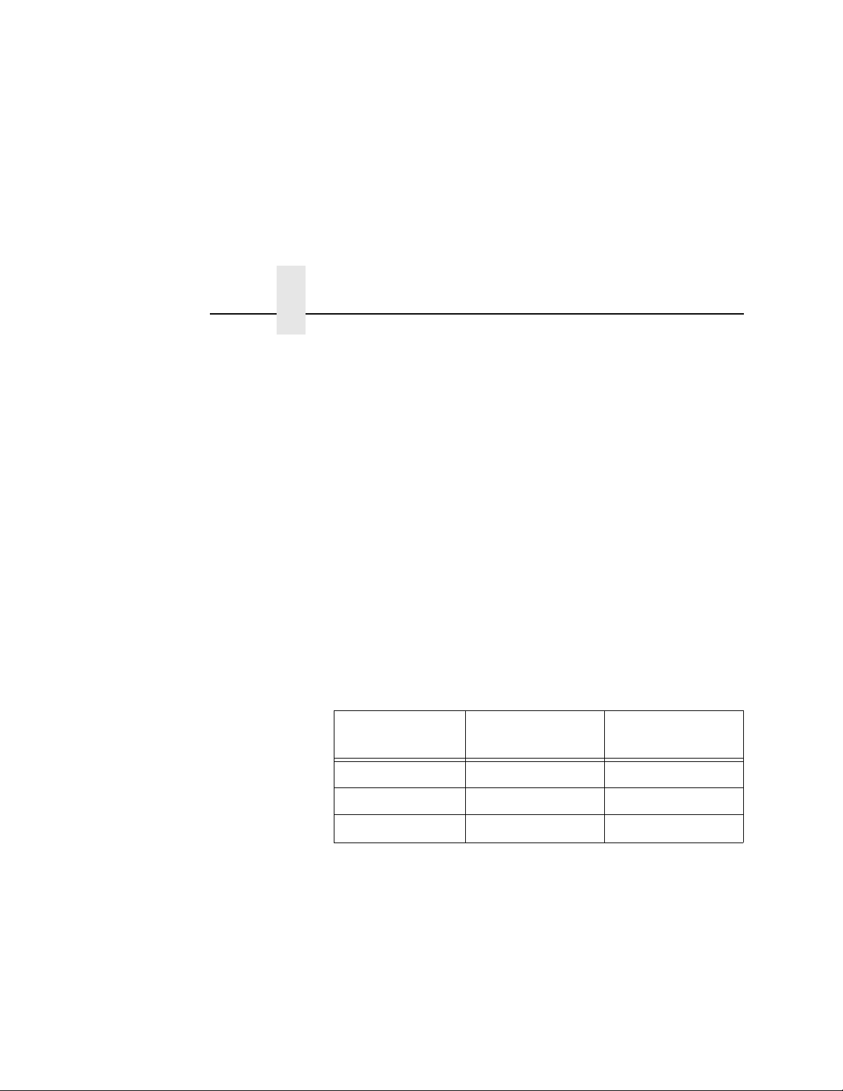
Refer to Table 1 for the minimum x-dimension requirements for
each printer size of a 300 dpi printer.
Table 1: Minimum X-Dimension and Beam Width for
a 300 dpi Printer
14
Printer Size Beam Width
4 inch 4.5 inches 6.6 mil
6 inch 6.5 inches 10 mil
8 inch 8.5 inches 13 mil
X-Dimension
Minimum
Page 15

Tools and Materials You will Need
•
SL5000r/T5000r User’s Manual
•
Static wrist strap*
•
2.5 mm hex key*
•
#2 Phillips Screwdriver*
Parts List
•
3 mm hex key
•
Validator and mounting screws
•
Validator bracket, mounting screws, and skew adjustment
screw
•
Extended Media Width Guide*
•
Cable ties, black
•
Bar code calibration card
•
Ferrite*
•
Cable assembly*
•
Wire saddle*
•
Grommet*
•
ODV Interface PCBA (used for SL/T5000r Energy Star models
only)
* Only for a field installation
15
Page 16
Chapter 1
183453b
CAUTION
MADE IN U.S.A. by Printronix
CANADA ICES/NMB-003 CLASS/CLASSE B
Scan Distance:
CAUTION
LASER RADIATION. DO NOT STARE INTO BEAM
CLASS 2 LASER PRODUCT
ATTENTION
RAYONNEMENT LASER. NE PAS REGARDER DANS LE FAISCEAU.
APPARELL À LASER DE CLASSE 2
ACHTUNG
LASERSTRAHLUNG NICHT IN DEN STRAHL BLICKEN
LASER KLASSE 2
LASER RADIATION
DO NOT STARE INTO BEAM
CLASS 2 LASER PRODUCT
PRODUCT CONFORMS TO DHHS REGULATIONS
21 CFR SUBCHAPTER J
Wavelength: 660-680nm
Maximum Output: 3mW
IEC 60826-1:2007
C
A
U
T
ION
C
L
A
S
S
3
B
L
A
S
E
R
RA
DIA
T
I
O
N
W
HE
N
OP
E
N
A
V
O
I
D
E
X
P
O
S
U
R
E
T
O
T
H
E B
E
A
M
CAUTION
CLASS 3B LASER RADIATION WHEN OPEN
AVOID EXPOSURE TO THE BEAM
Note: This is the
laser exit window.
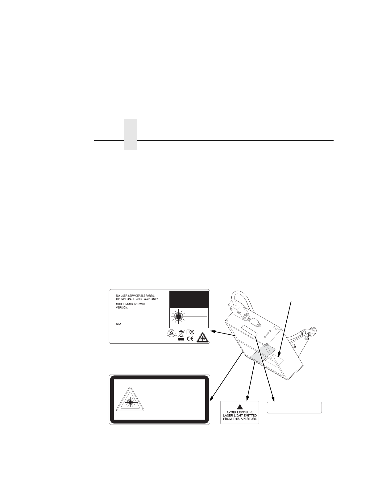
Safety Notices
Safety Noti ces
The validator is a Class 2 laser product. The following notices apply
at all times when the printer is powered on and the validator is
active:
WARNING
WARNING
Class 2 laser light. Do not stare into the laser beam or a
reflected image of the laser beam.
Using controls, making adjustments, or performing
procedures other than those specified herein may result in
hazardous radiation exposure.
16
Figure 1. Safety Warnings
Page 17

Installa tion and Removal
This section describes how to install the validator. To remove the
validator, reverse the steps of this procedure.
Prepare the Printer
1. Set the printer power switch to O (Off).
Prepare the Printer
WARNING
Always unplug the printer power cord from the printer or
power outlet before doing any installation procedure. Failure
to remove power could result in injury to you and damage the
equipment. You will be instructed when to apply power.
2. Unplug the printer power cord from the printer or the AC power
source.
Factory Installation
If your printer has a factory installed validator, the ferrite, cable, wire
saddle, grommet, and extended media width guide have already
been installed. Go to “Install the Validator” on page 28.
Field Installation
If you are doing a field installation, you must install the ferrite, cable,
wire saddle, grommet, and extended media width guide. Go to
“Install the Ferrite” on page 18.
17
Page 18
Chapter 1
183454a
ETH
ER
N
E
T
PARAL
L
E
L
U
S
B
GP
I0
RS232
STAT
US
D
EBU
G
Captive Screw (2)
Frame Side Cover
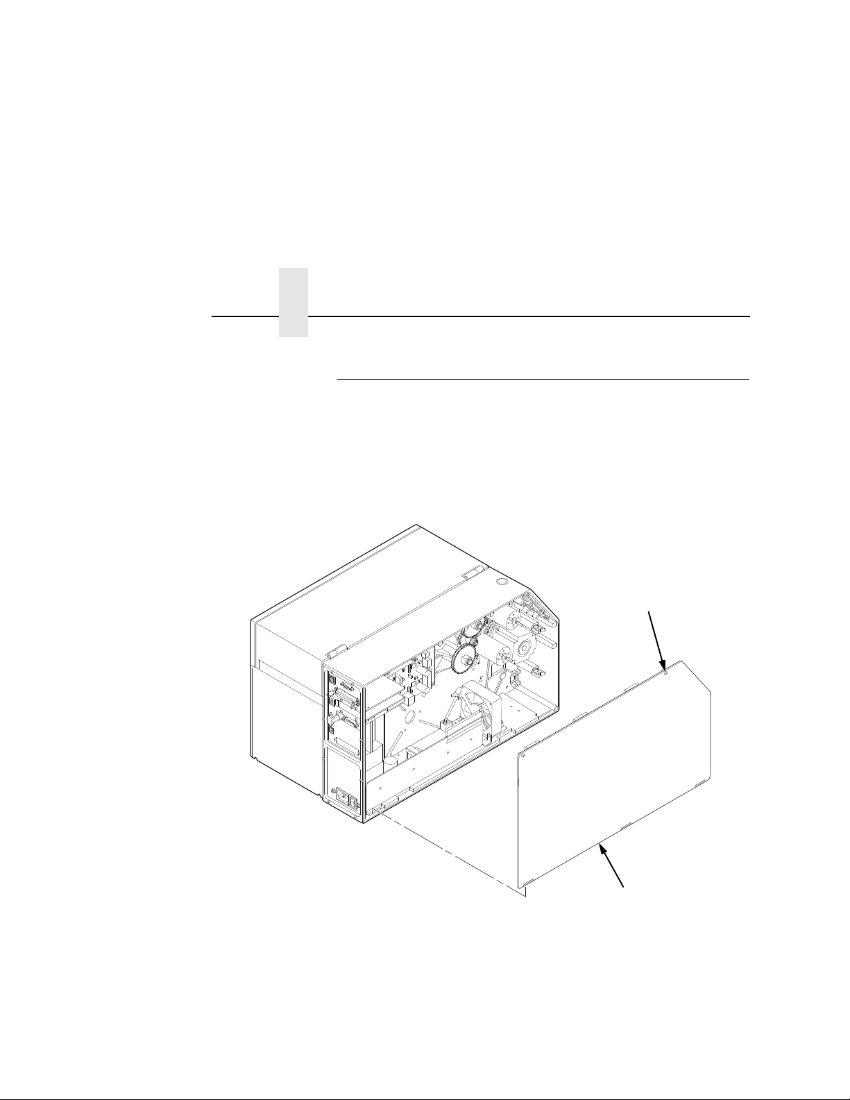
Installation and Removal
Install the Ferrite
1. Loosen the two captive screws securing the top of the frame
side cover. (
2. Tilt the frame side cover back from the top and lift it until the
tabs along the lower edge disengage from the slots in the
printer frame.
Figure 2.)
Figure 2. Removing the Frame Side Cover
18
Page 19
183455a
±
20.0 0.5
inches
DB15 Connector
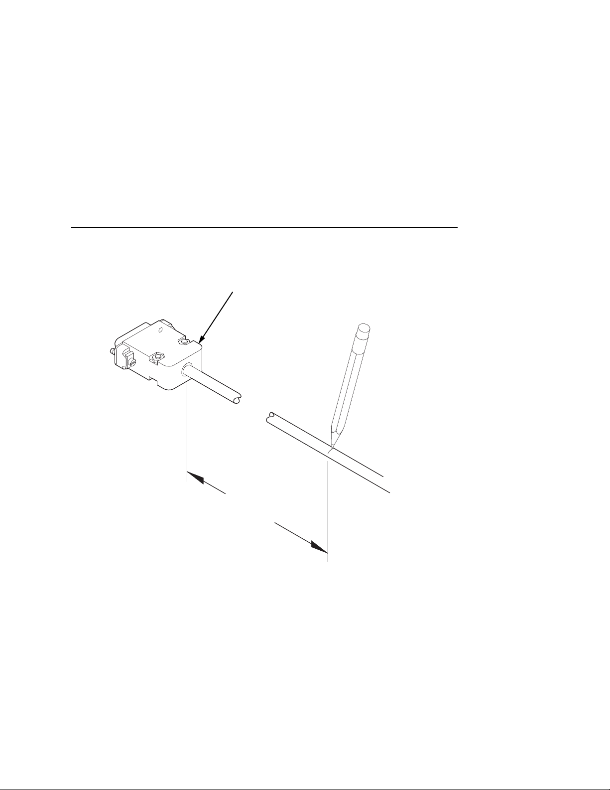
Install the Ferrite
Figure 3. Locating the Ferrite Position on the Power/Data
Cable
3. Stretch the Power/Data cable out straight on a flat surface.
4. Measure back 20.0 ± 0.5 inches from the DB15 connector and
mark the cable with a pencil line. (
Figure 3.)
19
Page 20
Chapter 1
183456a
P10 Connector
Plastic Plug
Frame Opening
Installation and Removal
CAUTION
20
Figure 4. Routing the Power/Data Cable
To prevent electrostatic damage to electronic components,
always wear a properly grounded static wrist strap when you
handle circuit boards.
5. Put on a static wrist strap and ground it to an unpainted part of
the printer frame. Touch the frame with the hand wearing the
wrist strap.
6. Raise the media cover and remove the plastic plug from the
frame opening.
7. Gently press the small wires of the P10 connector end of the
power/data cable against the connector and route the
connector through the frame opening. (
Figure 4.)
Page 21
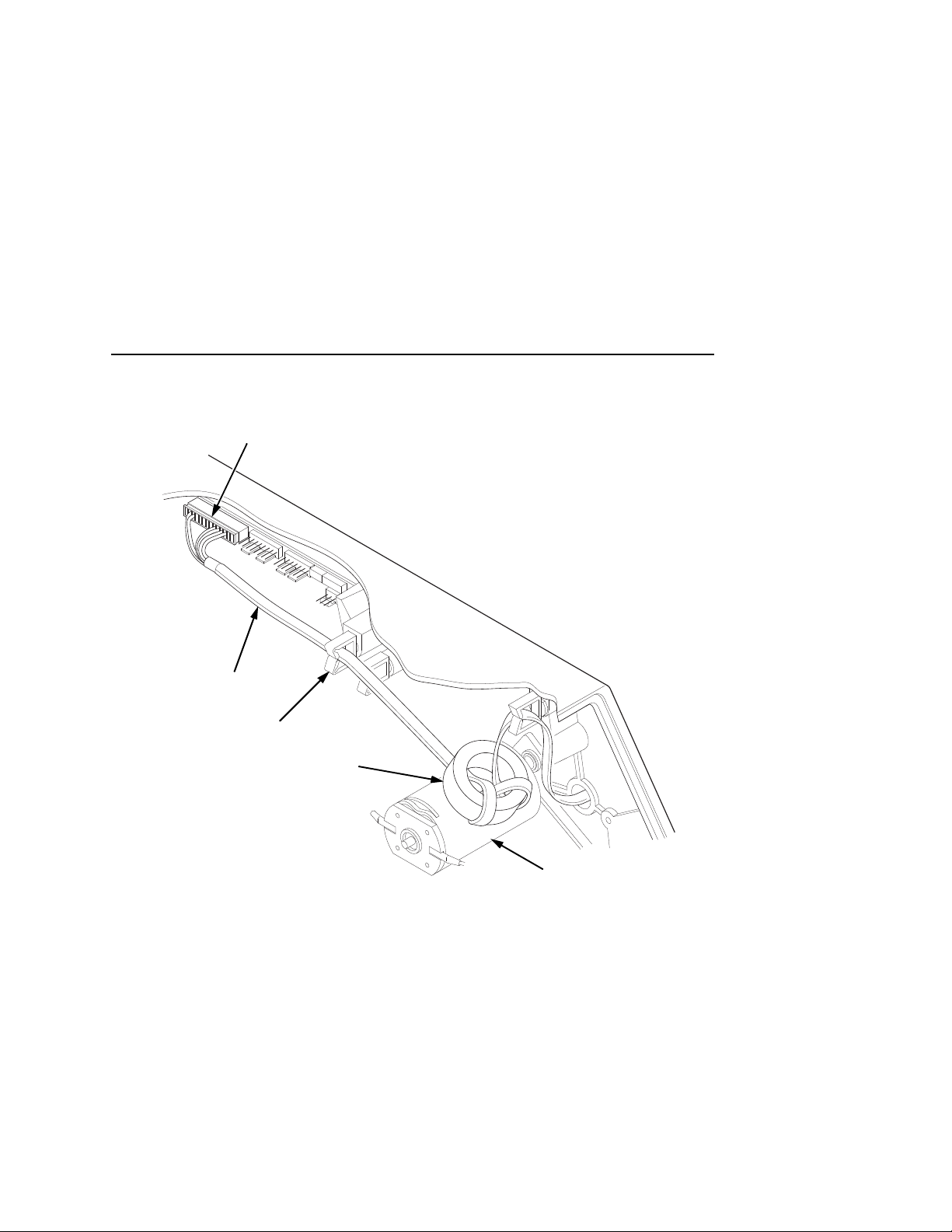
Install the Ferrite
183457a
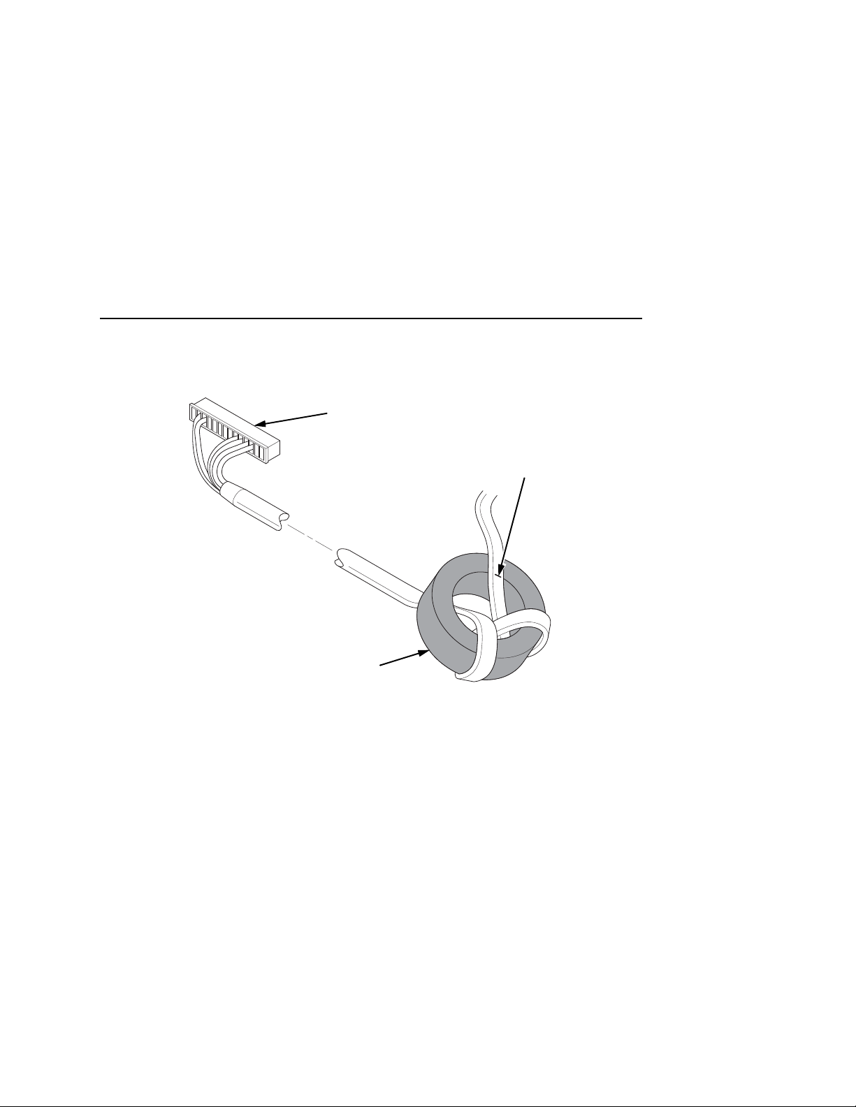
P10 Connector
(to controller board)
Ferrite
Pencil Line
Figure 5. Wrapping the Power/Data Cable Around the Ferrite
8. Using the P10 connector end of the power/data cable, insert
the cable through the ferrite. (
9. Wrap the power/data cable around the ferrite twice.
Figure 5.)
10. Adjust the position of the ferrite so that the length from the
ferrite to the DB15 connector is 20 ± 0.5 in
ches
.
21
Page 22
Chapter 1
183458a
Frame Boss
Wire Saddle
Installation and Removal
Figure 6. Inserting the Wire Saddle Into the Frame Boss
11. Insert the wire saddle into the frame boss. (Figure 6.)
22
Page 23

183459a
Ferrite
Wire Saddle
Frame
Opening
Install the Ferrite
Figure 7. Routing the Power/Data Cable From the Hole in the Frame Wall
12. Route the power/data cable through the wire saddle.
23
Page 24
Chapter 1
183460a
Split
Grommet
Power/Data Cable
(approximately
17 inches exposed)
Inserted Split
Grommet
(media side)
DB15
Connector
Installation and Removal
24
Figure 8. Adding the Grommet to the Power/Data Cable
13. On the media side of the printer, slide the split grommet onto
the power/data cable and insert it into the frame opening.
(
Figure 8.)
14. Inspect the power/data cable to ensure approximately
17
inches of cable is exposed from the grommet to connect it to
the validator.
NOTE: You will plug the power/data cable into the validator later.
Page 25
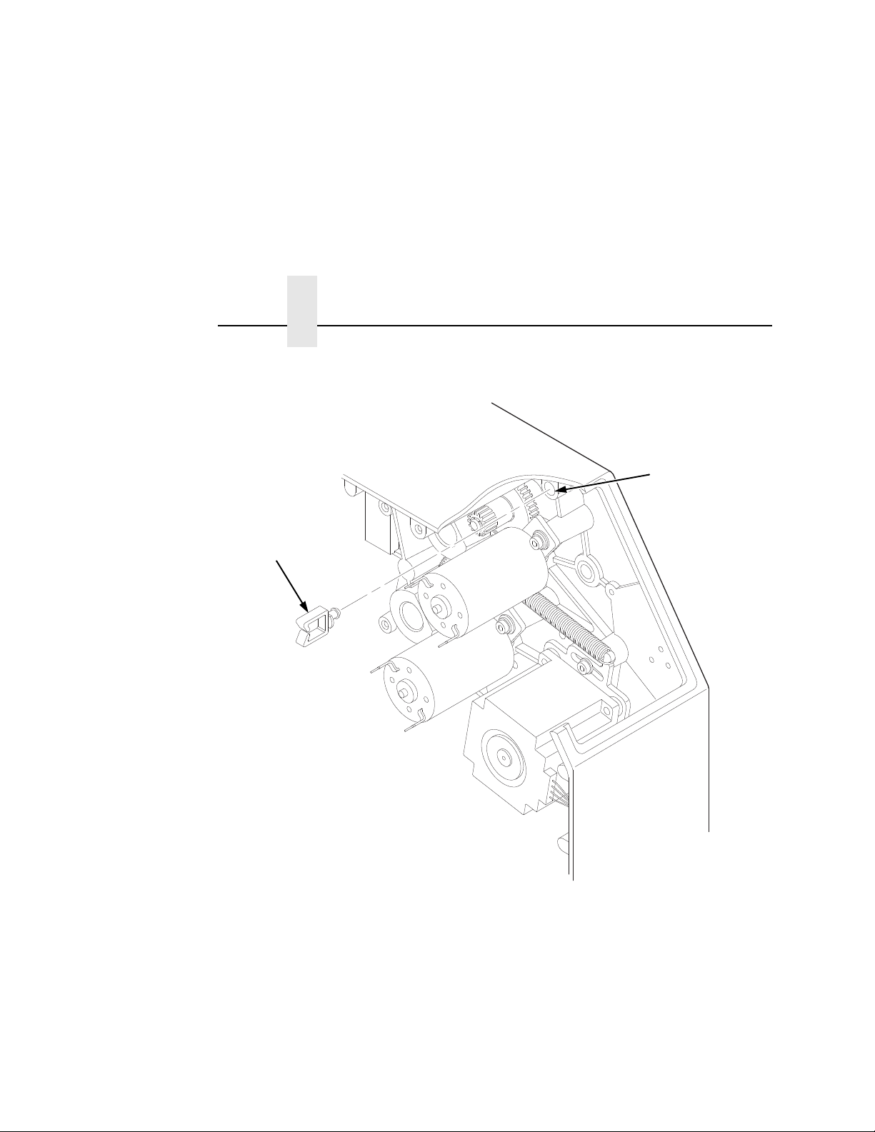
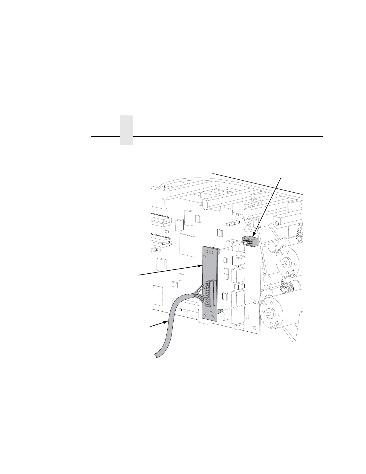
183461a
J10
Power/Data Cable
Ferrite
Upper
DC Motor
Wire Saddle
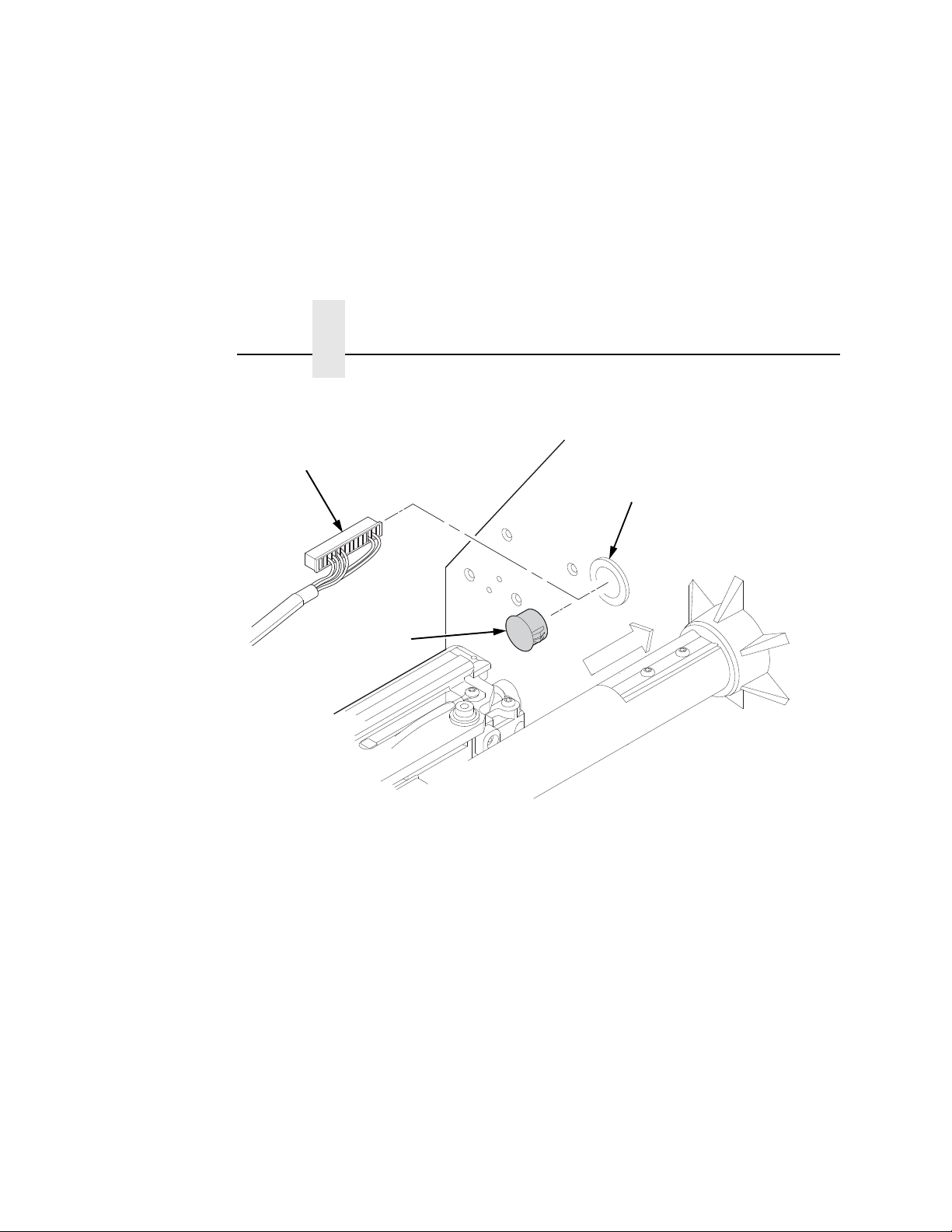
Install the Ferrite
Figure 9. Position the Ferrite
15. On the electronics side of the printer, position the ferrite on top
of the upper DC motor. (
Figure 9.)
16. Route the power/data cable through the wire saddle as shown
in
Figure 9.
17. Plug the P10 connector end of the power/data cable into the
J10 receptacle on the controller board.
NOTE: For SL5000r/T5000r Energy Star models see Figure 10 on
page 26.
25
Page 26
Chapter 1
183658a
J10
Power/Data Cable
ODV Interface
PCBA
Installation and Removal
Figure 10. SL/T5000r Energy Star Models – Plugging the Power/Data Cable into
the ODV Interface PCBA and then into the Controller Board
26
Page 27
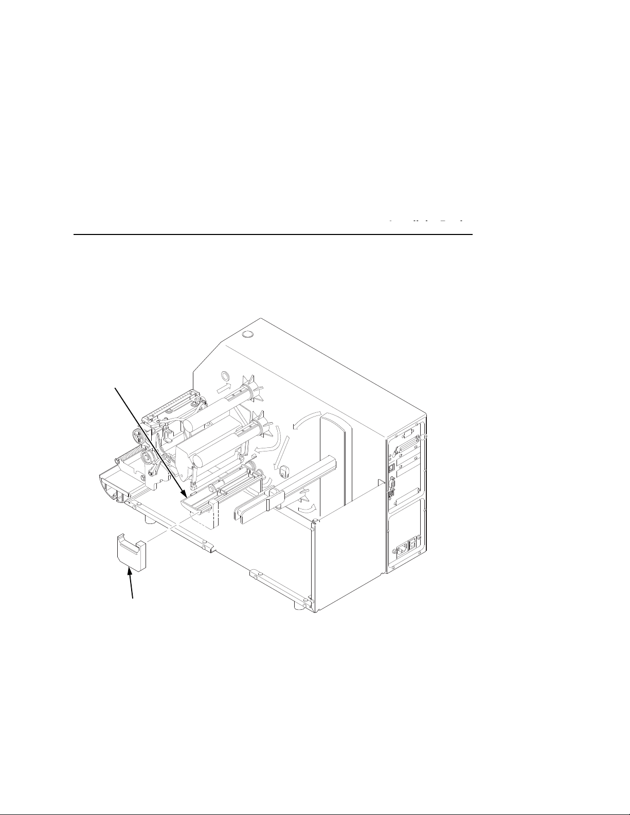
GPIO
USB
RS232
STA
TUS
DEBUG
P
ARALLEL
184232a
Extended Media
Width Guide
Media Damper
NOTE: The media cover is
removed for clarity in this
view. Do not remove the
media cover for this
procedure.
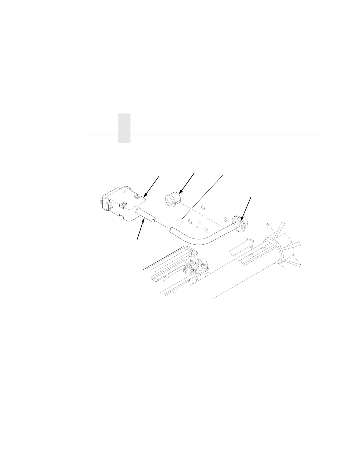
Install The Extended Media Width Guide
Install the Ferrite
Figure 11. Replacing the Media Width Guide
18. Replace the standard (blue) media width guide on the media
damper with the extended media width guide (
Figure 11).
27
Page 28
Chapter 1
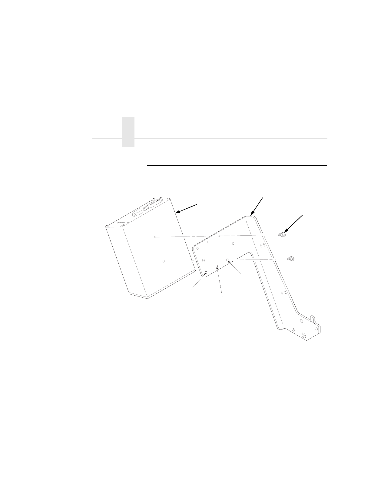
183339a
8”
Printer
6”
Printer
4”
Printer
Bracket
6-32 Phillips
Screw (2)
Validator
Installation and Removal
Install the Validator
28
Figure 12. Attaching the Validator to the Bracket
1. Using two 6-32 Phillips head screws, attach the validator to the
bracket as shown in
2. Use the appropriate holes on the bracket, depending on the
media width.
Figure 12.
Page 29
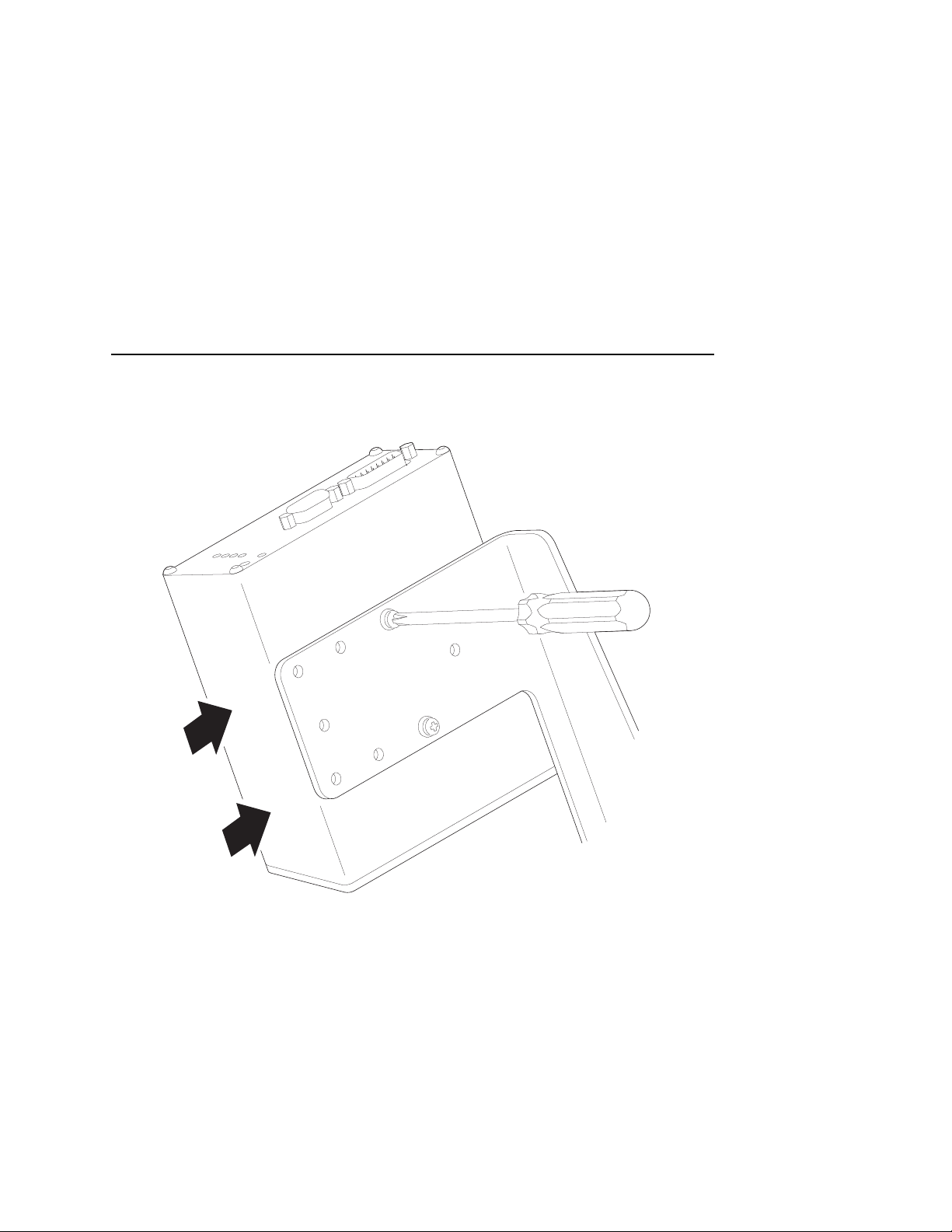
Install the Validator
183340a
Figure 13. Positioning the Validator on the Bracket
1. Apply even pressure to the side of the validator as you tighten
the screws on the bracket as shown in
Figure 13.
2. Make sure the validator is firmly seated against both screws to
insure proper beam alignment.
29
Page 30
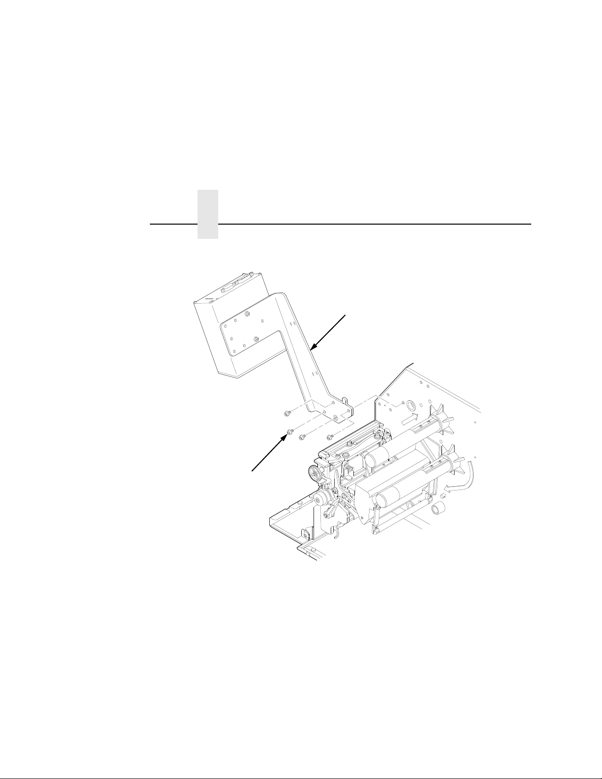
Chapter 1
183341a
Validator/Bracket Unit
M4x10mm
Screw (4)
Installation and Removal
Figure 14. Attaching the Validator/Bracket Unit to the Printer
30
3. Face the front of the printer while installing the validator/
bracket unit.
4. Using four M4x10mm screws, attach the validator/bracket unit
to the printer frame as shown in
5. Tighten the four screws finger tight. You will adjust the
Figure 14.
validator/bracket unit in a later step using the 3mm hex key
(provided).
Page 31

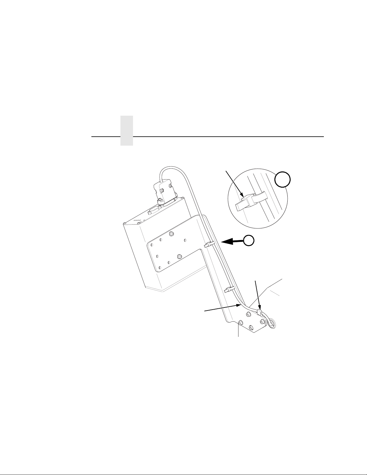
Attach the Power/Data Cable
183342a
Tie Wrap (2)
Power/Data Cable
DB15 Connector
Validator
Bracket
First Upper
Slot
Attach the Power/Data Cable
Figure 15. Attaching the Power/Data Cable
1. Plug the DB15 connector end of the power/data cable into the
validator.
2. Route the power/data cable along the inside of the bracket, as
shown in
Figure 15.
3. Route a tie wrap from the inside of the bracket through the first
upper slot as shown in
Figure 15, keeping the power/data cable
underneath the tie wrap.
31
Page 32
Chapter 1
183343a
A
A
Tie Wrap Head
Bracket Tab
Power/Data Cable
Installation and Removal
.
32
Figure 16. Securing the Power/Data Cable
4. Route the tie wrap back through the second upper slot and
underneath the power/data cable and then through the tie wrap
head, as shown in Detail A of
5. Pull the tie wrap just enough to hold the cable in place, but do
not over tighten it.
6. Repeat step 3 through step 5 using the lower pair of slots.
7. Route the power/data cable behind the bracket tab as shown in
Figure 16.
NOTE:
If necessary, loosen the bracket mounting screws enough
to slip the power/data cable behind the bracket tab, then
retighten the bracket mounting screws.
Figure 16.
Page 33

8. Gently pull the power/data cable to minimize the slack along
and behind the bracket. Push any excess slack through the
grommet.
9. Once the power/data cable is properly positioned, pull the tie
wraps snug against the cable and bracket and cut off the
excess.
Restore the Printer to Operation
1. Lower the media cover.
2. Engage the tabs on the bottom of the frame side cover in the
slots in the printer frame.
3. Rotate the cover into position.
4. Tighten the two captive screws. (Figure 2.)
5. Plug the AC power cord into the printer and the power source.
6. Set the printer power switch to | (On).
Attach the Power/Data Cable
33
Page 34

Chapter 1
.
.
.
.
.
.
Enable the Validator
Enable the V alidator
IMPORTANT
NOTE:
Software can automatically detect an installed validator when the
printer is powered up. If the printer is powered up with Power-Up
Config. set to Factory, the VALIDATOR menu will be available and
Validator Funct. is set to Enable in the QUICK SETUP and
VALIDATOR menus.
If Power-Up Config. is not set to Factory, the VALIDATOR menu
appears, but Validator Funct. is set to Disable. Enable Validator
Funct. by completing the following steps. (This is a one-time setting
once you save the configuration.)
Do not enable or disable the validator with data in the buffer.
See “Resetting Validator Data” on page 56.
1. Press to take the printer offline and place the printer in
2. If necessary, press ↓ and ↵ at the same time to unlock the
3. Press until VALIDATOR displays.
If you make any changes to the default configuration menu
items, you will be prompted to save the configuration when
you attempt to put the printer online. See “Auto Save
Configuration” in the
Menu mode.
↵
key. (This key combination can be changed by the user. Use
the customer’s key combination if necessary.)
User’s Manual
.
4. Press ↓ until Validator Funct. displays.
5. Press + or – until the Enable displays.
6. Press ↵ to enable the validator. An asterisk (*) should appear
after Enable. Once enabled, the printer will command the
validator to begin scanning and reporting errors, and the
counters will be incremented.
7. Press ↓ and ↵ at the same time to lock the ↵ key, then press
PAUSE
8. Press
34
to take the printer offline.
PAUSE
again to put the printer online.
Page 35
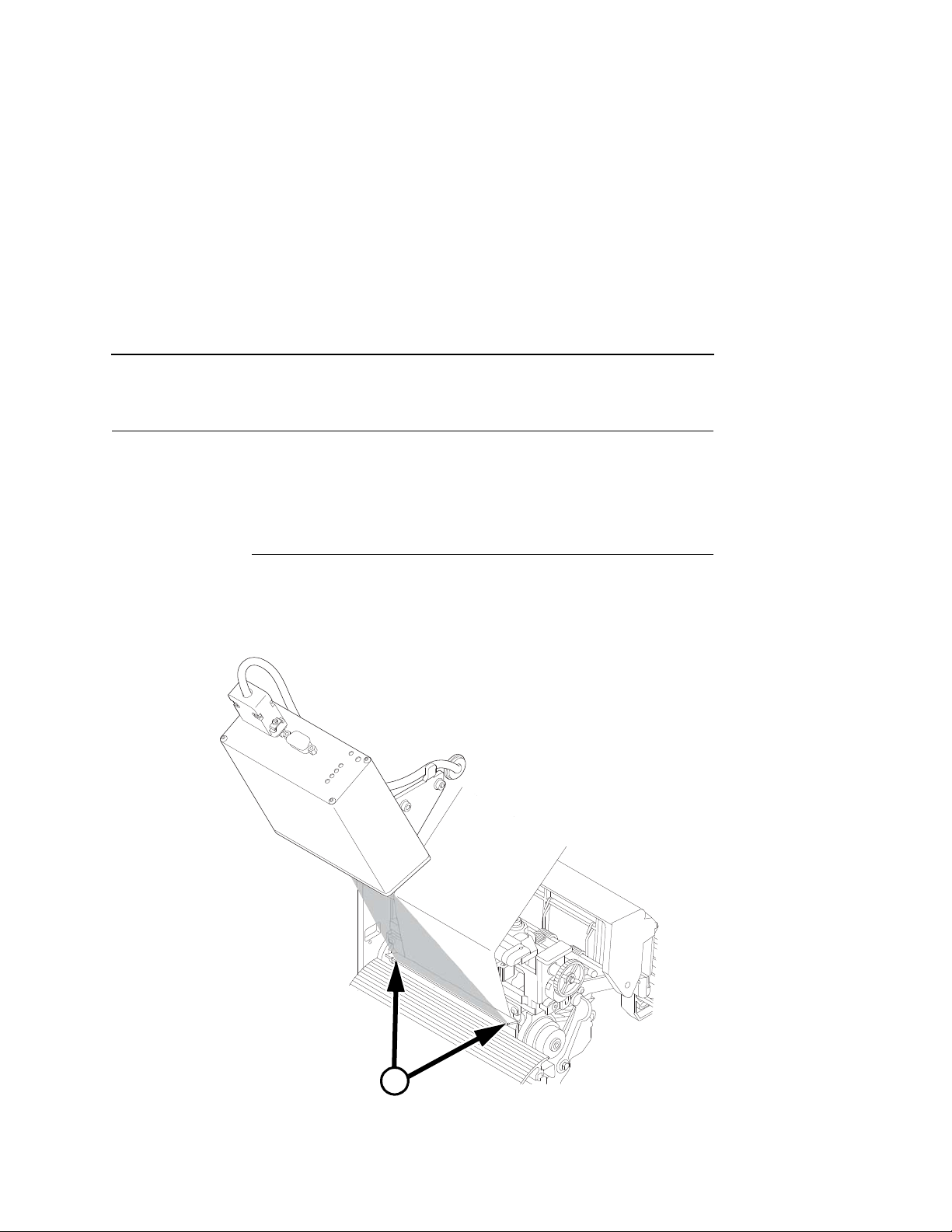
Adjust the Scanning Be am
183462a
A
See Figure 18, Detail A
on page 36.
Continuous, Tear-Off, and Tear-Off Strip
NOTE:
Make sure the printer is on and the scanning beam is on. If
the beam is off, press the
seconds to turn on the beam.
RESET
button for less than 2
Continuous, Tear- Off, and Tear-Off Strip
When the validator is first installed, the scanning beam may need to
be aligned with the two notches on the sides of the tear bar, as
shown in Detail A of Figure 17. When the scanning beam is
properly aligned it will line up with the two notches.
Figure 17. Aligning the Scanning Beam: Continuous, Tear-Off, and Tear-Off Strip
Media Handling Modes Only
35
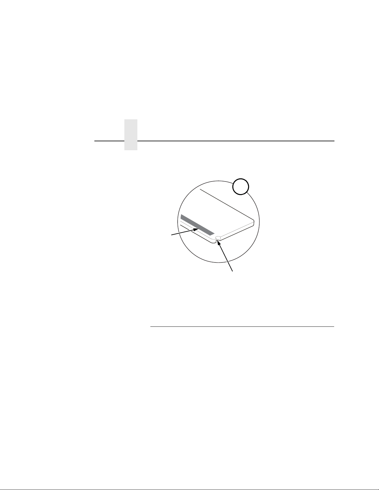
Page 36
Chapter 1
183463a
A
Notch in Tear Bar
Scanning Beam
From Figure 17
on page 35.
Adjust the Scanning Beam
Figure 18. Scanning Beam Location
36
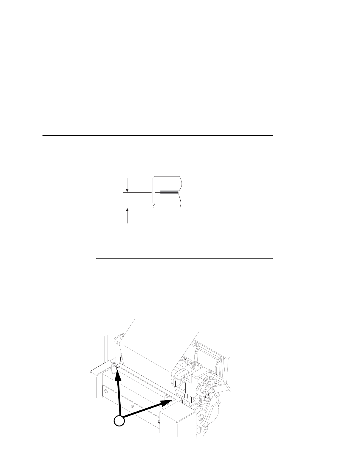
Peel-Off Media Handling Mode
If your printer is configured for Peel-Off Media Handling mode (use
of optional internal rewinder), you may need to align the beam
further behind the notches (0.14 to 0.20 inches [3.56 mm to
5.07 mm] from the front edge of the tear bar) so that the peeled
label remains on the tear bar and the trailing edge of the last bar
code can still pass completely under the scanning beam. See
Figure 19.
Aligning the scanning beam to any position other than the notches
on the tear bar should only be done if the last printed bar code
image does not clear the beam when the label is at the peel-off
position after printing. In addition, the distance the beam moves
back from the tear bar edge must correspond to a distance from the
leading edge of the label that does not have bar code printing. For
example, aligning the beam 0.16 inches from the front edge of the
tear bar requires that 0.16 inches of the leading edge of the label
must not have bar code images.
Page 37
Cut Media Handling Mode
183464a
0.20 inches
(5.07 mm)
183465a
183465a
A
See Figure 21,
Detail A on
page 38.
Figure 19. Aligning the Scanning Beam: Peel-Off Media Handling Mode Only
Cut Media Handling Mode
If your printer has a cutter installed and is configured for Cut Media
Handling Mode, align the beam at the notches at each side of the
opening on the upper enclosure, as shown in Detail A of Figure 20.
IMPORTANT
Figure 20. Aligning the Scanning Beam: Cutter Installed
The beam must make direct contact with the media, not the
inside metal part of the cutter. See Figure 22 for instructions
on how to adjust the vertical position of the beam.
37
Page 38

Chapter 1
183466a
A
Scanning Beam
Notch in the Upper
Enclosure Cutter
From Figure 20
on page 37.
Adjust the Scanning Beam
Figure 21. Scanning Beam Location: Cutter Installed
38
Page 39

Cut Media Handling Mode
183344a
Pivot Screw
M4 x 6 mm
Screw
NOTE:
Only needed if laser beam
skew adjustment is required.
NOTE:
Loosen all four screws
to adjust the beam
forward or back.
Front
Figure 22. Scanning Beam Adjustment Screws
Figure 22 shows the screws used to adjust the position of the
scanning beam. The positions of the screws assume that you are in
front of the validator unit and facing the printer. The following
instructions and illustrations show how to adjust the validator
according to how the beam appears.
1. Power the printer on and make sure the scanning beam is on. If
the beam is off, press the
RESET
button for less than 2
seconds to turn on the scanning beam.
2. Use the hex key provided to adjust the screws.
3. Loosen the four screws so the validator/bracket unit can be
rotated about the pivot screw.
39
Page 40
Chapter 1
Tear Bar
Adjust the Scanning Beam
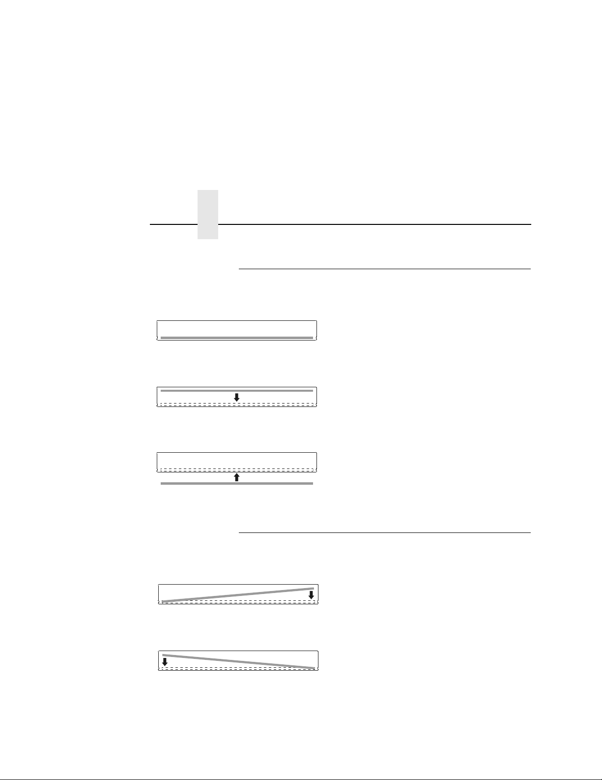
Scanning Beam V ertical Alig nment
Correct vertical alignment of the scanning
beam. The beam lines up with the end
notches and is parallel to the long edge of
the tear bar.
Raise the validator/bracket unit to move
the scanning beam forward.Once the
beam is correctly aligned with the end
notches, tighten the four screws.
Lower the validator/bracket unit to move
the scanning beam back. Once the beam
is correctly aligned with the end notches,
tighten the four screws.
Scanning Beam Skew Adjustment
Install the M4 x 6 mm screw in the right
threaded (outboard) hole and use the 3
mm allen wrench to gradually turn the
screw clockwise until the beam is parallel.
Install the M4 x 6 mm screw in the left
threaded hole and use the 3 mm allen
wrench to gradually turn the screw
clockwise until the beam is parallel.
40
Page 41

Shif ting the Scanning Beam
.
.
.
.
.
.
This option enables you to shift the scanning beam horizontally to
the left or right. The left edge of the beam should be approximately
0.25 inches (6.35 mm) past the left edge of the tear bar or the upper
enclosure of a cutter assembly. After you set this value, save it as
part of the configuration for future use.
The value range is from –99 to 99. The default is 0. Lower values
will move the beam to the left.
Scanning Beam Skew Adjustment
NOTE:
You must set Admin User to Enable (in the PRINTER
CONTROL menu) to access the Beam Shift option.
(Refer to the
User’s Manual
.)
1. Press to take the printer offline and place the printer in
Menu mode.
2. If necessary, press ↓ and ↵ at the same time to unlock the
↵
key.
3. Press until VALIDATOR displays.
4. Press ↓ until Validator Funct. displays.
5. Make sure Enable is selected.
6. Press ↑ until Beam Shift displays.
7. Press + or – to scroll through the values: –99 to 99. The default
↵
is 0. Lower values will move the beam to the left. Press
to
accept the shift value.
Keep selecting the new value until the beam width is at the
desired position. The left edge of beam should be
approximately 0.25 inches (6.35 mm) past the left edge of the
tear bar or the upper enclosure of a cutter assembly.
8. Save the configuration for future use. (Refer to Saving A
Configuration in the
User’s Manual
.)
41
Page 42

Chapter 1
Calibration
Calibration
WARNING
WARNING
Time RESET Button Is Depressed Result
Class 2 laser light. Do not stare into the laser beam or a
reflected image of the laser beam.
Using controls, making adjustments, or performing
procedures other than those specified herein may result in
hazardous radiation exposure.
The validator should be calibrated when it is first installed or when
the printer displays Calibration warning. A special calibration bar
code card is included with the validator package.
1. Make sure the printer is powered on and in offline mode, and
that the validator power light and scanning beam are on. If the
beam is off, press the
turn on the beam.
NOTE:
In SL5/T5R Energy Star models, the Power Save mode
powers the validator off. Press the FEED key to restore
power and turn on the beam within 21 seconds.
Table 2. RESET Button Settings
RESET
button for less than 2 seconds to
Less than 2 seconds Turns on the scanning beam
More than 4 but less than 6 seconds Validator goes into calibration mode
More than 6 seconds Resets validator to the last good calibration
settings and turns off the scanning beam
2. If the printer has the cutter option, put the cutter in the open
(down) position.
3. Remove the calibration bar code card from its protective sleeve
and slide the top edge between the printhead and platen and
Figure 23.)
42
under the scanning beam. (
NOTE:
Do not unlock the deck lock lever.
Page 43

Scanning Beam Skew Adjustment
183467a
CALIBRATION
Light
RESET Button
Deck Lock
Lever
Calibration Bar
Code Card
4. Make sure the bar code is under the scanning beam.
5. Press and hold the
RESET
button on the validator for 4 to 6
seconds until the READ light illuminates and the
CALIBRATION light begins flashing.
Figure 23. Calibrating the Validator
6. Within a few seconds the CALIBRATION and READ light will
turn off. This indicates a successful calibration.
NOTE:
If the calibration light is still on or flashing, the calibration
has failed. In this case, refer to
Table 2 on page 42 to
repeat the calibration procedure or to reset the validator
settings back to the last good calibration settings.
7. Once you have a successful calibration, remove the calibration
bar code card.
43
Page 44

Chapter 1
Calibration
8. Power the printer off, wait a few seconds, then power the
printer on.
If the calibration was successful, the scanning beam is on and
the CALIBRATION light is off.
If the calibration was not successful, the scanning beam
remains on and the CALIBRATION light stays lit without
flashing. Repeat the calibration procedure. If repeated attempts
fail, check the room for excessive ambient light, including direct
sunlight. You may need to move the printer to a darker area of
the room.
NOTE:
In some cases the validator can detect and indicate to the
printer that calibration is required. See “Calibration
warning” in
Table 6 on page 97.
Bar Code Validation Demo Page
The bar code validation demo page allows you to test or
demonstrate the validator operation without a host computer. This
page contains some text and two good bar code symbologies: one
in Code 39, the other in Code 128. (Min. label size 2” W x 1” L)
NOTE:
If Label Length is less than 0.5 inches or Label Width is less than
2.0 inches, no demo page will print.
To print and validate the bar code validation demo page:
1. Load the factory default configuration. (Refer to the
2. In the VALIDATOR menu, set Validator Funct. to Enable.
3. In the CALIBRATE CTRL menu, set Gap/Mark Sensing to Gap.
4. Load media.
In the QUICK SETUP or MEDIA CONTROL menu, if Label
Length is set between 0.5 and 1.0 inches, only the Code
128 bar code will print.
User’s
Manual
.)
44
5. In the CALIBRATE CTRL menu, run Auto Calibrate for proper
gap sensing.
6. The printer must be offline. If the printer is in Menu mode, press
the
PAUSE
key to take the printer offline.
Page 45

Bar Code Validation Demo Page
7. Press the
Continue to press
8. Press the ↵ key to print and validate the demo page. (If the ↵
key is locked, unlock it by pressing
9. The printer will print one demo page.
10. To demonstrate a bad bar code reading, block the scanning
beam with an opaque object while the bar code moves under
the beam. When you block the beam, the validator will generate
a reading error and will perform a default error action. The
default setting for the Validator Action in the VALIDATOR menu
is Retry Form. Using the factory default settings, the printer will
pull the label with the bad barcode back, overstrike the entire
label, reprint the barcodes on the next label and then stop.
11. Press
12. Press ↓ and ↵ at the same time to lock the ↵ key, then press
PAUSE
TEST PRINT
PAUSE
to take the printer offline.
to place the printer back online.
key to enter the Test Print menu.
TEST PRINT
until Barcode Demo displays.
↓
and ↵ at the same time.)
45
Page 46

Chapter 1
Calibration
46
Page 47

2
Operation
Basic V alid ator Setup
Unit Positioning
The validator must be positioned so that the scanning beam covers
the entire area containing the bar codes, including the area
required for quiet zones. The beam width can be moved
horizontally to the left or right (see “Shifting the Scanning Beam” on
page 41).
If a bar code is completely outside of the scanning area, straddles
an edge, or does not pass completely under the scanning beam,
the validator interprets it as a missing bar code and generates error
conditions.
V alidato r Front Pan el
The front panel of the validator has the following controls and
indicators:
• POWER:
• CALIBRATION:
mode. See
• READ:
• 1
and
• RESET:
long you hold the button down. See
Indicates the validator is at full power.
Flashes when the validator is in calibration
page 42 for calibration instructions.
Flashes when the validator is reading a bar code.
2:
Used for maintenance purposes only.
This button has three functions, depending on how
Table 3 on page 48.
47
Page 48

Chapter 2
Time RESET Button Is Depressed Result
Less than 2 seconds Turns on the scanning beam
More than 4 but less than 6 seconds Validator goes into calibration mode
More than 6 seconds Resets validator to the last good calibration
Basic Validator Setup
Table 3. RESET Button Settings
settings and turns off the scanning beam
CAUTION
CAUTION
Do not lift the printer by the validator unit or by the bracket.
The validator contains sensitive electronic equipment. Do not
jar or drop the unit.
48
Page 49
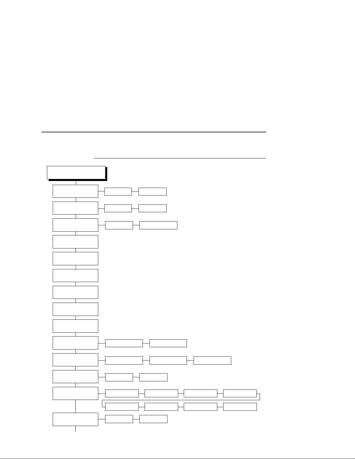
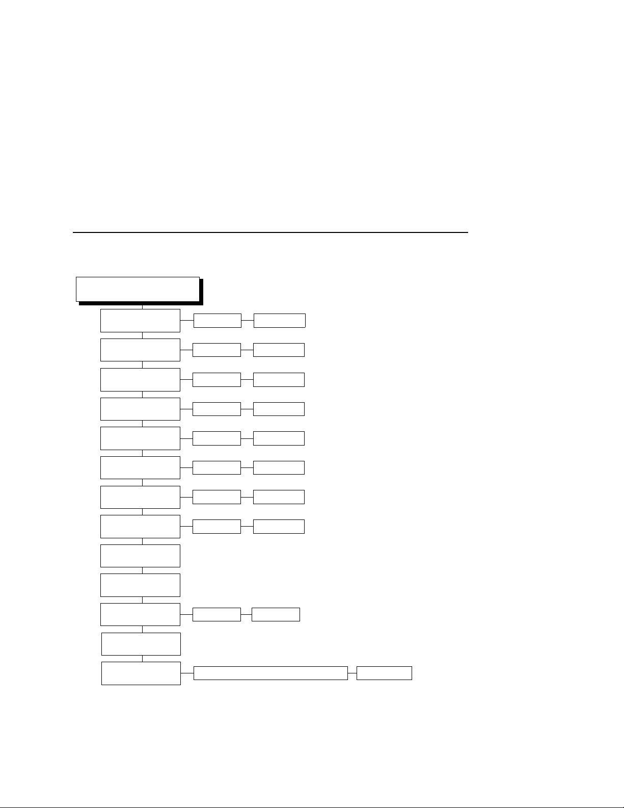
VALIDATOR
1 second* 1 to 10 seconds
Short Report*
(cont. on next page)
Notes:
* = Default
Italicized items appear only when
Admin User is set to Enable (in the
PRINTER CONTROL menu).
1
Display item only
Full Report Validation Mode
Disabled* Network Port
Auto* 1 to 99
Disable* Enable
Auto Report
page 55
Clear Data
page 56
Good Forms
1
page 58
Good Barcodes
1
page 58
Overstrike Forms
1
page 58
Average BWD
1
page 58
Last BWD
1
page 58
Auto Report Time
page 55
Telemetry Pat h
page 56
Telemetry Data
page 57
Number of Codes
page 59
Retry Form* Stop & Retry Grade&Report
Validator Ac t i on
page 90
Enable* Disable
Validator Funct.
page 53
Rescan&Retry Stop Overstrike
Rescan Form
Rescan&Stop
Enable* Disable
Quiet Zones
page 60
VALIDATOR Menu
VALIDAT OR Menu
49
Page 50
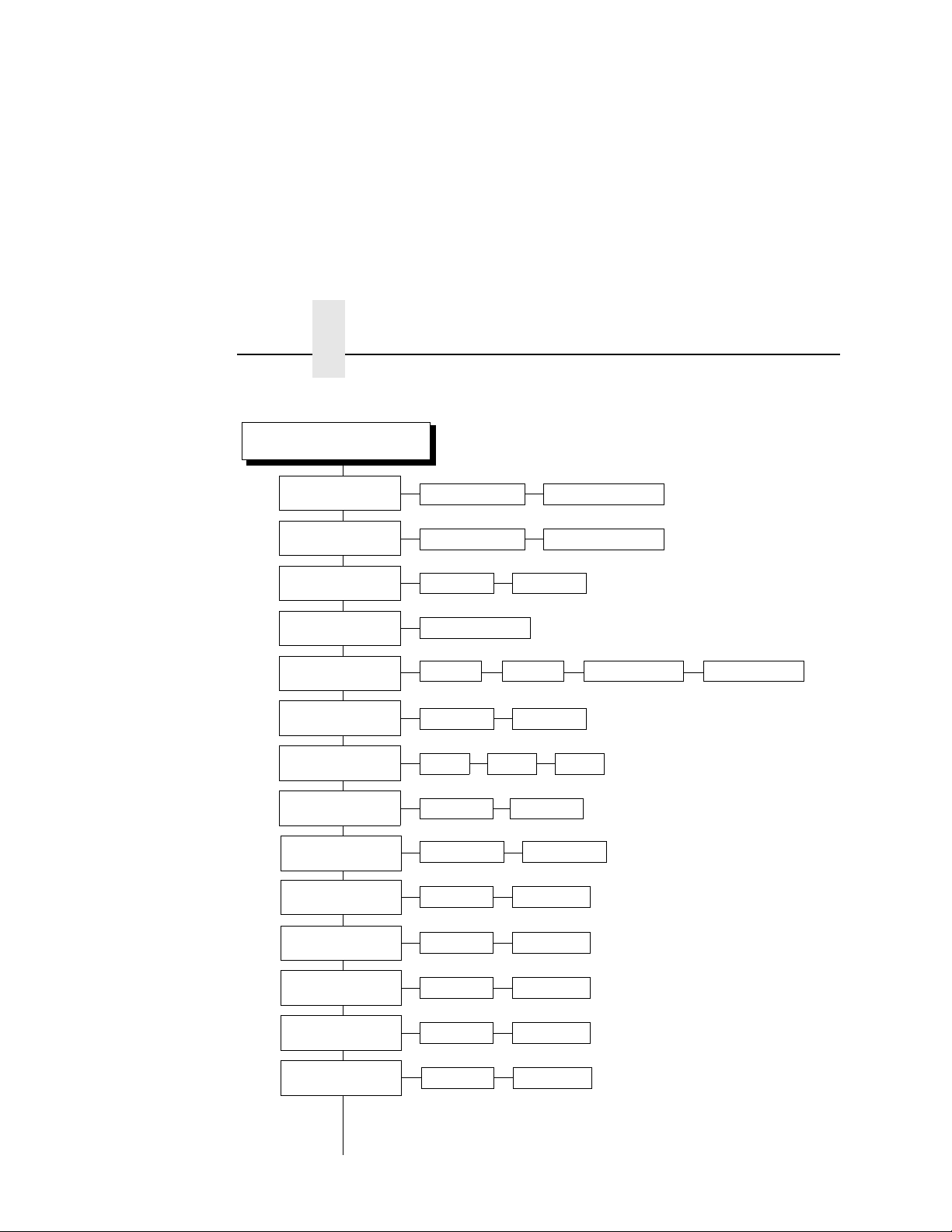
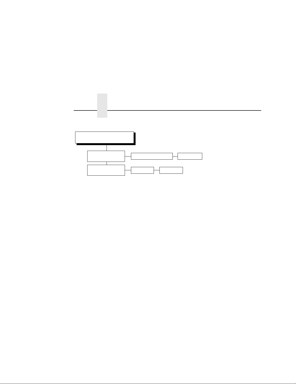
VALIDATOR
(cont. from previous page)
Minimum* Maximum
Disable* Enable
0.15 to 1.00 inches0.30 inches*
Notes:
* = Default
Italicized items appear
only when Admin User
is set to Enable (in the
PRINTER CONTROL
menu).
1
Display item only.
Min. Code Gap
page 87
Skip Labels
page 61
I2of5 Checksum
page 62
5* 3
Num Retry
page 63
4
0.13 to 1.00 inches0.30 inches*
Min. Code Height
page 85
Version: xxxx
1
F/W Revision
page 60
37%* 30% to 90%
0%* 0% to 99%
21%* 0% to 100%
Decodeability
page 64
Percent Decode
page 65
Defects
page 65
Grid* Error Type MsgCheckerboard
Overstrike Style
page 61
Grey
Dump Form* Keep Form
Max Retry Action
page 63
Num Rescan
page 63
1* 1 to 5
0.0* 0.0 to 4.0
Overall Grade
page 66
(cont. on next page)
Disable* Enable
Label Save
page 64
Chapter 2
Basic Validator Setup
50
Page 51
VALIDATOR
(cont. from previous page)
0 to 255
0% to 100%0%*
Notes:
* = Default
Italicized items appear only when Admin User is set to Enable (in the PRINTER CONTROL menu).
2
Depends on the printer model: 4, 6, and 8 inch printers respectively. xx, yy, z z = file revision numbers.
3
Appears only if feature files have been downloaded to the printer. Up to seven files can appear.
4
Depends on the printer model: 4, 6, and 8 inch printers respectively.
Gain
page 71
Scan Repor t
page 74
0% to 100%100%*
Rmin
page 69
Print Settings
page 79
Profile H Mag
page 78
1* 1 to 4
0 to 255
Offset
page 71
5 to 19970*
SN Threshold
page 72
Symbol Contrast
page 70
Scan Profile
page 76
Default 4xx, Default 6yy, or Default 8zz*
2
Scanner Settings
page 81
feature files
3
0*
0*
2 to 992*
Min. Read Scans
page 73
0%* 0% to 100%
EC Min
page 69
Modulation
page 68
0%* 0% to 100%
VALIDATOR Menu
51
Page 52
Chapter 2
VALIDATOR
(cont. from previous page)
Notes:
* = Default
Italicized items appear only when Admin User is set to Enable (in the PRINTER CONTROL menu).
2
Depends on the printer model: 4, 6, and 8 inch printers respectively. xx, yy, zz = file revision numbers.
3
Appears only if feature files have been downloaded to the printer. Up to seven files can appear.
4
Depends on the printer model: 4, 6, and 8 inch printers respectively.
0* –99 to 99
Beam Shift
page 83
1800, 2550, or 3100*
4
250 to 3100
Beam Width
page 82
Basic Validator Setup
52
Page 53

Configuring the Validator
.
.
.
.
.
.
Setting validator options is done through the printer configuration
menu. The validator comes equipped with a default setting for each
configuration option, and it works without having to change any of
these options. However, in some cases it is necessary to adjust
these options, which are described below.
Enabling and Disabling the Validator
IMPORTANT
NOTE:
If you make any changes to the default configuration menu
items, you will be prompted to save the configuration.
See “Auto Save Configuration” in the
User’s Manual
.
Enabling and Disabling the Validator
Software can automatically detect an installed validator when the
printer is powered up. If the printer is powered up with Power-Up
Config. set to Factory, the VALIDATOR menu will be available and
Validator Funct. is set to Enable in the QUICK SETUP and
VALIDATOR menus.
If Power-Up Config. is not set to Factory, the VALIDATOR menu
will be available, but Validator Funct. is set to Disable. Enable
Validator Funct. by completing the following steps. (This is a onetime setting once you save the configuration.)
Do not disable or enable the validator with data in the buffer.
See “Resetting Validator Data” on page 56.
1. Press to take the printer offline and place the printer in
Menu mode.
2. If necessary, press ↓ and ↵ at the same time to unlock the
↵
key.
3. Press until VALIDATOR displays.
4. Press ↓ until Validator Funct. displays.
5. Press + or – until Enable displays.
6. Press ↵ to enable the validator. An asterisk (*) should appear
after Enable. Once enabled, the printer will command the
validator to begin scanning and reporting errors, and the
counters will be incremented.
53
Page 54

Chapter 2
Configuring the Validator
7. Press ↓ and ↵ at the same time to lock the ↵ key, then press
PAUSE
to take the printer offline.
8. Press
NOTE:
PAUSE
To disable the validator once it has been enabled, repeat
step 1 through step 8 and select Disable in step 5.
again to put the printer online.
RFID Encoder
If you have an RFID encoder but are not encoding RFID tags, make
sure RFID Reader is set to Disable (in the RFID CONTROL menu),
otherwise the validation process will slow down considerably as the
RFID encoder attempts to scan for non-existent RFID tags.
V alidat or Reporting
After any completed print job or Bar Code Demo page, you can
request a report from the printer which describes the validation
statistics since the printer was turned on, or since the last data
reset (for information on resetting data, see page 56).
Requesting a Validator Report
This procedure prints a summarized validator report. (This report
also includes RFID data if the printer has an RFID encoder.)
1. Press the
PAUSE
key to take the printer offline.
54
2. If necessary, press ↓ and ↵ at the same time to unlock the
↵
key.
3. Press
4. Press + until RFID/ODV Report displays.
5. Press ↵ to print the report.
6. Press ↓ and ↵ at the same time to lock the ↵ key, then press
7. Press
PAUSE
TEST PRINT
to take the printer offline.
PAUSE
. Printer Tests displays.
again to put the printer online.
Page 55

Validator Reporting
.
.
.
.
.
.
.
.
.
.
.
.
Setting Auto Report
This function allows you to disable or enable an automatic validator
report printout after a batch job or Bar Code Demo page. The
default is Disable.
You can determine the end of a batch job in two ways:
•
by using an Execute command, or
•
by enabling the Auto Report Time (see below).
To enable Auto Report:
1. Press to take the printer offline and place the printer in
Menu mode.
2. If necessary, press ↓ and ↵ at the same time to unlock the
↵
key.
3. Press until VALIDATOR displays.
4. Press ↓ until Auto Report displays.
5. Press + or – to scroll through the choices: Enable or Disable.
The default is Disable.
6. When Enable displays, press ↵ to activate Auto Report.
7. Press ↓ and ↵ at the same time to lock the ↵ key, then press
PAUSE
8. Press
to take the printer offline.
PAUSE
again to put the printer online.
Setting Auto Report T ime
This function allows you to set, in seconds, the timeout for the Auto
Report. If the printer is idle for the set number of seconds, an Auto
Report will be generated if Auto Report is set to Enable (see
“Setting Auto Report” on page 55.) The default is 1 second.
To set the Auto Report Time:
1. Press to take the printer offline and place the printer in
Menu mode.
2. If necessary, press ↓ and ↵ at the same time to unlock the
↵
key.
3. Press until VALIDATOR displays.
4. Press ↓ until Auto Report Time displays.
55
Page 56

Chapter 2
.
.
.
.
.
.
.
.
.
Configuring the Validator
5. Press + or – to scroll through the choices: 1 to 10 seconds. The
default is 1 second.
6. When the desired number of seconds displays, press ↵ to set
the Auto Report Time.
7. Press ↓ and ↵ at the same time to lock the ↵ key, then press
PAUSE
8. Press
to take the printer offline.
PAUSE
again to put the printer online.
Resetting Validator Data
The validator reports on all bar codes it detects since the last data
reset. For example, you print a large batch of labels with bar codes
and then print a validator report. Then you print another batch of
labels with bar codes and print another report. The report will
contain information on both batch jobs. However, if you reset the
validator data between batch jobs, the second report will only
contain information on the second batch job.
To reset Validator Data:
1. Press to take the printer offline and place the printer in
Menu mode.
2. If necessary, press ↓ and ↵ at the same time to unlock the
↵
key.
3. Press until VALIDATOR displays.
4. Press ↓ until Clear Data displays.
5. Press ↵ to clear validator data.
6. Press ↓ and ↵ at the same time to lock the ↵ key, then press
PAUSE
7. Press
to take the printer offline.
PAUSE
again to put the printer online.
Defining the Data Ou tput Destination (Telemetry Path)
You may want to send a streaming flow of validation data to an
external device during the print job. The default is Disabled. Follow
the procedure below to select the data output destination.
1. Press to take the printer offline and place the printer in
Menu mode.
56
Page 57

Validator Reporting
.
.
.
.
.
.
.
.
.
2. If necessary, press ↓ and ↵ at the same time to unlock the
↵
key.
3. Press until VALIDATOR displays.
4. Press ↓ until Telemetry Path displays.
5. Press + or – to cycle through the choices:
• Disabled.
Default setting. The validator does not send any
data to an external device.
• Network Port.
The printer outputs the bar code analysis
and underlying data from the validator to a device
connected to the network port so the validator data can be
seen and analyzed with the optional remote management
software.
6. When your selection displays, press ↵ to activate it. All future
reports are output to your selection.
7. Press ↓ and ↵ at the same time to lock the ↵ key, then press
PAUSE
8. Press
Selecting the Type Of Report for the
to take the printer offline.
PAUSE
again to put the printer online.
Data Output Destination (Telemetry Data)
By default, the validator sends the Short Report to the selected data
output destination, but there are two other report options available:
Full Report and Validation Mode.
1. Press to take the printer offline and place the printer in
Menu mode.
2. If necessary, press ↓ and ↵ at the same time to unlock the
↵
key.
3. Press until VALIDATOR displays.
4. Press ↓ until Telemetry Data displays.
5. Press + or – to cycle through the choices:
• Short Report.
Default setting. Provides the encoded failure
cause or pass indication and the bar width deviation,
shown as a percentage.
57
Page 58

Chapter 2
.
.
.
.
.
.
Configuring the Validator
• Full Report.
Provides a completed report of all the data
captured by the validator.
• Validation Mode.
Provides the same data as the Short
Report, but adds the actual bar code data read.
6. When your selection displays, press ↵ to activate it.
7. Press ↓ and ↵ at the same time to lock the ↵ key, then press
PAUSE
8. Press
to take the printer offline.
PAUSE
again to put the printer online.
Validator Statistics
The validator displays a number of statistics directly on the printer
LCD, without having to print a report. To view any of the statistics:
1. Press to take the printer offline and place the printer in
Menu mode.
2. If necessary, press ↓ and ↵ at the same time to unlock the
↵
key.
3. Press until VALIDATOR displays.
4. Press ↓ to scroll through the following statistics on the printer
display:
• Good Barcodes:
from the validator since the last Clear Data command.
• Good Forms:
printed since the last Clear Data command.
• Overstrike Forms:
code that fell below the minimum acceptable level since the
last Clear Data command.
• Average BWD:
reported since the last Clear Data command, shown as a
percentage.
• Last BWD:
recent report received from the validator, shown as a
percentage.
The number of bar code reports sent
The number of good (non-overstruck) forms
The number of forms containing a bar
The average of all Bar Width Deviations
The Bar Width Deviation included in the most
NOTE:
A bar code’s Bar Width Deviation is determined by
comparing the bar width the validator expects to the bar
width that is actually printed. For example, if the bar width is
58
Page 59

Defining Validator Options
.
.
.
.
.
.
printed exactly as the validator expects, the BWD is 0%.
However, if the bar width as printed is 25% wider or narrower
than the validator expects it to be, it reports a BWD of 25%.
5. Press ↓ and ↵ at the same time to lock the ↵ key, then press
PAUSE
to take the printer offline.
6. Press
PAUSE
again to put the printer online.
Defining Validator Options
A number of validator options which define specific parameters for
certain print jobs can be set from the printer configuration menu.
Setting Number of Bar Codes on a Form
You can define how many bar codes the validator should expect on
a form. This setting is required when bar codes are produced as a
part of a larger bitmapped image. When set to a specific number,
the printer checks after a form has printed and passed the validator
and determines if it has received an analysis report for each bar
code. If the printer does not have as many reports as it expects, it
assumes a gross bar code failure.
When Auto (the default) is selected, the printer only expects as
many bar code analyses as bar codes printed using printer bar
code commands defined by the host software.
1. Press to take the printer offline and place the printer in
Menu mode.
2. If necessary, press ↓ and ↵ at the same time to unlock the
↵
key.
3. Press until VALIDATOR displays.
4. Press ↓ until Number of Codes displays.
5. Press + or – to scroll through the choices: Auto, 1 to 99. The
default is Auto.
6. Press ↵ to select the desired value.
7. Press ↓ and ↵ at the same time to lock the ↵ key, then press
PAUSE
8. Press
to take the printer offline.
PAUSE
again to put the printer online.
59
Page 60

Chapter 2
.
.
.
.
.
.
.
.
.
.
.
.
Configuring the Validator
Checking Quiet Zones
Quiet zones are the white spaces surrounding the bar code. Each
bar code requires a minimum quiet zone distance in order for the
bar code to be scanned properly.
NOTE:
The validator requires a minimum distance of 1/2” or 20
times the minimum element width (x-dimension), whichever
is greater, between bar codes.
When set to Enable (the default), then the bar code quiet zone is
included as part of the pass/fail criteria.
1. Press to take the printer offline and place the printer in
Menu mode.
2. If necessary, press ↓ and ↵ at the same time to unlock the
↵
key.
3. Press until VALIDATOR displays.
4. Press ↓ until Quiet Zones displays.
5. Press + or – to scroll through the choices: Enable or Disable.
The default is Enable.
6. Press ↵ to select the desired value.
7. Press ↓ and ↵ at the same time to lock the ↵ key, then press
PAUSE
8. Press
NOTE:
to take the printer offline.
PAUSE
again to put the printer online.
The validator does not recognize x-dimensions greater
than 40 mil with Quiet Zones enabled.
Checking the Firmware Revision Number
For troubleshooting purposes, you may need to reference the
firmware revision number.
1. Press to take the printer offline and place the printer in
Menu mode.
2. If necessary, press ↓ and ↵ at the same time to unlock the
↵
key.
3. Press until VALIDATOR displays.
4. Press ↓ until F/W Revision displays. The firmware revision
number displays.
60
Page 61

Defining Validator Options
.
.
.
.
.
.
.
.
.
5. Press ↓ and ↵ at the same time to lock the ↵ key, then press
PAUSE
to take the printer offline.
6. Press
PAUSE
again to put the printer online.
Setting for Skip Labels
This option is used for skipping blank labels after bad labels have
been marked. It is useful when you want to have extra blank labels
in between bad and good ones. The settings are Minimum (the
default) and Maximum. Minimum allows up to one blank label, and
Maximum allows up to two blank labels.
NOTE:
1. Press to take the printer offline and place the printer in
2. If necessary, press ↓ and ↵ at the same time to unlock the
3. Press until VALIDATOR displays.
4. Press ↓ until Skip Labels displays.
5. Press + or – to scroll through the choices: Minimum or
6. Press ↵ to select the desired value.
7. Press ↓ and ↵ at the same time to lock the ↵ key, then press
8. Press
Minimum and Maximum blank labels are only applicable for
forms 2 inches (5.08 cm) high or more. For labels less than
2 inches high, the minimum and maximum blank labels
may vary.
Menu mode.
↵
key.
Maximum. The default is Minimum.
PAUSE
to take the printer offline.
PAUSE
again to put the printer online.
Setting Overstrike Style
This option is used for marking bad labels with different overstrike
styles: Grid (the default), Grey, Checkerboard, or Error Type Msg.
IMPORTANT
If you are using an RFID encoder, set the validator Overstrike
Style different than the RFID Overstrike Style (in the RFID
CONTROL menu). This will help you differentiate between a
validator error and an RFID error.
1. Press to take the printer offline and place the printer in
Menu mode.
61
Page 62

Chapter 2
.
.
.
.
.
.
.
.
.
Configuring the Validator
2. If necessary, press ↓ and ↵ at the same time to unlock the
↵
key.
3. Press until VALIDATOR displays.
4. Press ↓ until Overstrike Style displays.
5. Press + or – to scroll through the choices: Grid, Grey,
Checkerboard, or Error Type Msg. The default is Grid.
6. Press ↵ to select the desired value.
7. Press ↓ and ↵ at the same time to lock the ↵ key, then press
PAUSE
to take the printer offline.
8. Press
PAUSE
again to put the printer online.
Setting I2of5 Checksum
This option allows you to include or exclude the checksum option in
the Interleaved 2 of 5 code as part of the grading. For example, if
you enable this option, then any incoming bar code data without
checksum digits will be graded as a failure, and a Checksum
Failure error will display. The default is Disable.
1. Press to take the printer offline and place the printer in
Menu mode.
2. If necessary, press ↓ and ↵ at the same time to unlock the
↵
key.
3. Press until VALIDATOR displays.
4. Press ↓ until I2of5 Checksum displays.
5. Press + or – to scroll through the options: Enable or Disable.
The default is Disable.
6. Press ↵ to accept the desired value.
7. Press ↓ and ↵ at the same time to lock the ↵ key, then press
PAUSE
8. Press
to take the printer offline.
PAUSE
again to put the printer online.
62
Page 63

Defining Validator Options
Num Retry
This option allows you to set the number of times a form will be
reprinted before the printer stops. After you clear the error
message, the printer will print the same form or the next form,
depending on the setting for Max Retry Action (see “Max Retry
Action” below).
The options are 3, 4, and 5. The default is 5.
NOTE:
This setting is utilized only when Validator Action is set to
Retry Form, Stop & Retry, or Rescan&Retry.
Action (Error Action)” on page 90.
See “Validator
Num Rescan
This option allows you to set the number of times a form will be
rescanned before the printer stops. After you clear the error
message, the printer will print the same label or the next label,
depending on the setting for Max Retry Action (see “Max Retry
Action” below).
The options are 1 to 5. The default is 1.
NOTE:
This setting is utilized only when Validator Action is set to
Rescan, Rescan&Retry, or Rescan&Stop.
Action (Error Action)” on page 90.
See “Validator
Max Retry Action
This option determines what the printer will do with the current form
once the Num Retry or Num Rescan counter has been exhausted
(see “Num Retry” or “Num Rescan” above).
If Max Retry Action is set to Dump Form, after you clear the fault
the form will be dumped and printing will resume with the next form.
If Max Retry Action is set to Keep Form, after you clear the fault
printing will resume with the same form again. It will not attempt to
print the next form until the problem form has printed correctly.
NOTE:
This setting is utilized only when Validator Action is set to
Retry Form, Stop & Retry, Rescan Form, Rescan&Retry, or
Rescan&Stop.
page 90.
See “Validator Action (Error Action)” on
63
Page 64

Chapter 2
.
.
.
.
.
.
Configuring the Validator
Advanced Validator Options
The following items are considered advanced items and are only
visible if Admin User is set to Enable (in the PRINTER CONTROL
menu). Refer to the configuration section of your
more information.
Label Save
The printer will often be printing a label when it determines that the
label printed before the immediate label was defective. When set to
disable, the printer pulls both labels back, overstrikes them and
then reprints them. With Label Save enabled, the ODV will accept
or reject the label it just printed before it prints the next label. Label
Save enabled causes a slight throughput reduction; when a label is
found defective, it will only overstrike that label. The default is
disable.
Decodeability
User’s Manual
for
NOTE:
You can determine how strict the validator grades the wide/narrow
bars and spaces which compose the bar code by setting the
Decodeability parameter to a percentage value from 30% to 90%.
The higher the percentage value chosen, the stricter the validator
grades. The default is 37%.
For example, if the Decodeability value is set to 37%, the validator
gives the bar code a failing grade if the decodeability of the bar
code is at or below 37%.
1. Press to take the printer offline and place the printer in
2. If necessary, press ↓ and ↵ at the same time to unlock the
3. Press until VALIDATOR displays.
4. Press ↑ until Decodeability displays.
5. Press + or – to scroll through the percentage values: 30% to
6. Press ↵ to select the desired value.
64
This parameter factors into the Overall Grade (page 66).
Menu mode.
↵
key.
90%. The default is 37%.
Page 65

Advanced Validator Options
.
.
.
.
.
.
7. Press ↓ and ↵ at the same time to lock the ↵ key, then press
PAUSE
to take the printer offline.
8. Press
PAUSE
again to put the printer online.
Percent Decode
NOTE:
You can set how strict the validator grades each bar code. For
example, setting Percent Decode to 60% means that 60% of the
scanned bar code must be readable for the validator to give the bar
code a passing grade. You can set the Percent Decode parameter
to a percentage value from 0% to 99%. The higher the percentage
value chosen, the stricter the validator grades.
1. Press to take the printer offline and place the printer in
2. If necessary, press ↓ and ↵ at the same time to unlock the
3. Press until VALIDATOR displays.
4. Press ↑ until Percent Decode displays.
5. Press + or – to scroll through the percentage values: 0% to
6. Press ↵ to select the desired value.
7. Press ↓ and ↵ at the same time to lock the ↵ key, then press
This parameter factors into the Overall Grade (page 66).
Menu mode.
↵
key.
90%. The default is 0%.
PAUSE
to take the printer offline.
8. Press
PAUSE
again to put the printer online.
Defects
NOTE:
You can set how strict the validator grades the irregularities such as
voids and spots found within elements and quiet zones for each bar
code. For example, the Defects default is 21%. This means that if
the bar code and quiet zone defects exceed 21%, the validator
gives the bar code a failing grade. You can set the Defects
parameter to a percentage value from 0% to 100%. The lower the
percentage value chosen, the stricter the validator grades.
This parameter factors into the Overall Grade (page 66).
65
Page 66
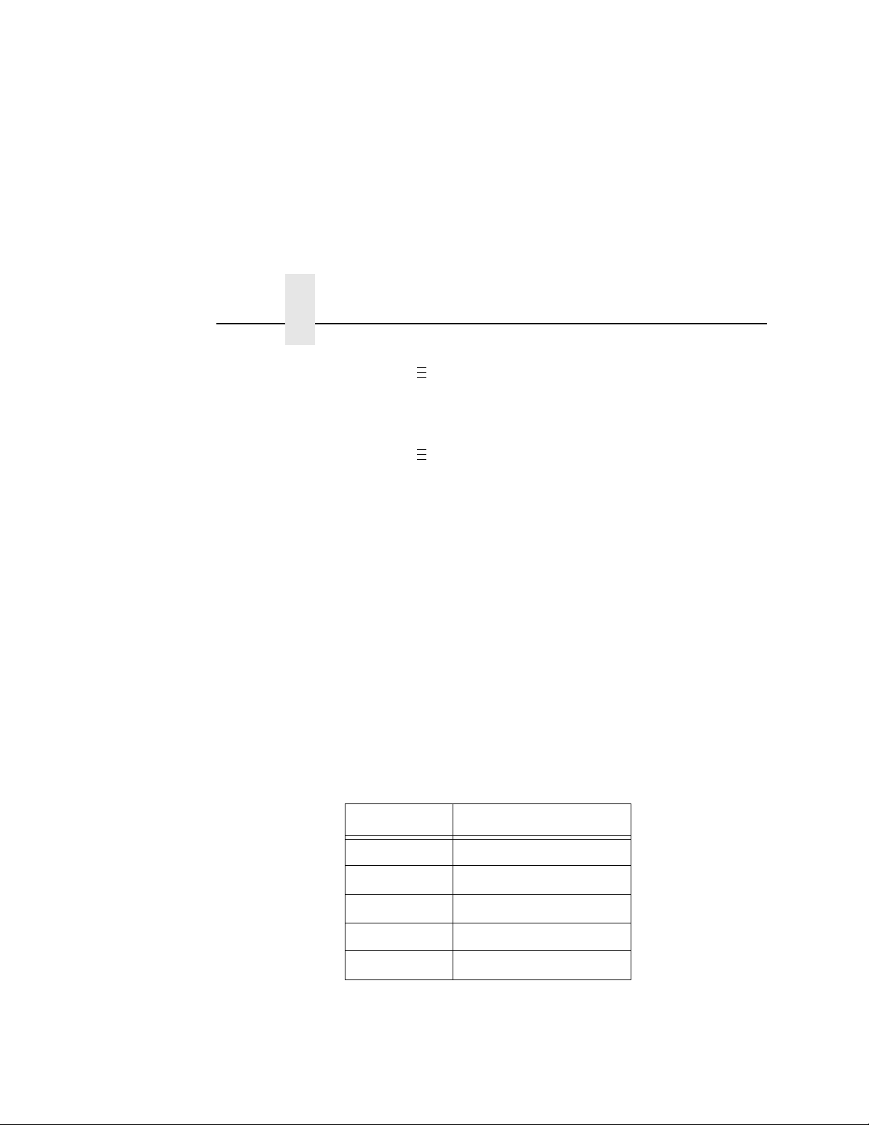
Chapter 2
.
.
.
.
.
.
Configuring the Validator
1. Press to take the printer offline and place the printer in
Menu mode.
2. If necessary, press ↓ and ↵ at the same time to unlock the
↵
key.
3. Press until VALIDATOR displays.
4. Press ↑ until Defects displays.
5. Press + or – to scroll through the percentage values: 0% to
100%. The default is 21%.
6. Press ↵ to select the desired value.
7. Press ↓ and ↵ at the same time to lock the ↵ key, then press
PAUSE
to take the printer offline.
8. Press
PAUSE
again to put the printer online.
Overall Grade
This menu item sets the value used by the validator for pass/fail
threshold during the analysis of bar codes. Instead of a letter grade,
numbers are used to allow for more resolution. The numbers can
be translated to letter grades according to the 4.0 grade table
below.
T able 4. Grading Scale for Overall Grade
Letter Grade Grade Numerical Range
A 3.5 to 4.0
B 2.5 to 3.4
C 1.5 to 2.4
D 0.5 to 1.4
F 0.0 to 0.4
Any bar code with a grade below this threshold value will cause the
printer to display the Overall Grade Fail error message (see “Error
Messages” on page 96) and take the appropriate error action.
Higher values create a stricter pass criterion.
66
Page 67

Advanced Validator Options
The Overall Grade is determined by taking the lowest grade
obtained for any of these bar code quality parameters:
Decodeability, Percent Decode, Defects, Modulation, EC Min,
Rmin, and Symbol Contrast.
You can set the Overall Grade parameter to a value from 0.0 to 4.0.
The default is 0.0.
Overall Grade Calculations
The validator follows the specified algorithm defined in the ANSI
X3.182 specification for determining the Overall Grade based on an
average. Although it is not defined, the validator truncates the result
of all analysis parameters averages for a slightly stricter grading.
A side effect of the ANSI specified algorithm is that the Overall
Grade may be lower than any of the averaged analysis parameters.
This occurs because the Overall Grade is based on the lowest
grade on any scan converted to a single digit grade (A to F, 4 to 0)
which is then averaged. This usually occurs when a single analysis
parameter has a value just above or just below the Overall Grade.
Example
The Decodeability value of 51 displays as B, but the Overall Grade
displays as C.
The bar code was scanned five times: three scans had values of
0.49 (grade C) and two scans had values of 0.54 (grade B).
The Decodeability grading calculation is:
(3 x 0.49) + (2 x 0.54) = 2.55
2.55 ÷ 5 = 0.51 (grade B)
The Overall Grade calculation is:
(3 x 2.0) + (2 x 3.0) = 12
12 ÷ 5 = 2.4 (grade C)
Also, with certain combinations of multiple analysis parameters and
possibly the truncation used on the analysis parameter’s average,
the Overall Grade may be higher than an individual analysis
parameter grade.
Example
The Decodeability value of 48 displays as C, but the Overall Grade
displays as B.
67
Page 68

Chapter 2
.
.
.
.
.
.
Configuring the Validator
The bar code was scanned five times: four scans had values of
0.51 (grade B) and one scan had a value of 0.40 (grade C).
The Decodeability grading calculation is:
(4 x 0.51) + (1 x 0.40) = 2.44
2.44 ÷ 5 = .49 (grade C)
The Overall Grade calculation is:
(4 x 3.0) + (1 x 2.0) = 14
14 ÷ 5 = 2.8 (grade B)
Modulation
NOTE:
This parameter factors into the Overall Grade (page 66).
Modulation measures how well the scan laser sees the wide
elements (bars or spaces) relative to the narrow elements. In
general, scanning lasers see bars better than spaces and wide
elements better than the narrow elements. This menu item sets the
value used by the validator for pass/fail threshold during the
analysis of bar codes. Higher values create a stricter criterion for
passing.
You can set the Modulation parameter to a percentage value from
0% to 100%. The default is 0%.
1. Press to take the printer offline and place the printer in
Menu mode.
2. If necessary, press ↓ and ↵ at the same time to unlock the
↵
key.
3. Press until VALIDATOR displays.
4. Press ↑ until Modulation displays.
5. Press + or – to scroll through the percentage values: 0% to
100%. The default is 0%.
6. Press ↵ to select the desired value.
7. Press ↓ and ↵ at the same time to lock the ↵ key, then press
PAUSE
to take the printer offline.
8. Press
PAUSE
again to put the printer online.
68
Page 69

EC Min
.
.
.
.
.
.
Advanced Validator Options
NOTE:
This parameter factors into the Overall Grade (page 66).
The higher the value, the stricter the criterion for passing.
This menu item sets the minimum edge contrast, which is the worst
edge transition (bar to space or space to bar) used by the validator
for pass/fail threshold during the analysis of bar codes. Bar codes
with an edge contrast below this threshold will fail.
You can set the EC Min parameter to a percentage value from 0%
to 100%. The default is 0%.
1. Press to take the printer offline and place the printer in
Menu mode.
2. If necessary, press ↓ and ↵ at the same time to unlock the
↵
key.
3. Press until VALIDATOR displays.
4. Press ↑ until EC Min displays.
5. Press + or – to scroll through the percentage values: 0% to
100%. The default is 0%.
6. Press ↵ to select the desired value.
7. Press ↓ and ↵ at the same time to lock the ↵ key, then press
PAUSE
8. Press
to take the printer offline.
PAUSE
again to put the printer online.
Rmin
NOTE:
This menu item sets the minimum reflectance value used by the
validator for pass/fail threshold used during the analysis of bar
codes. A bar code will fail if all the bar reflectance values are above
the percentage of space reflectance set by this threshold. For
example, an Rmin setting of 50% requires that at least one bar
reflectance value fall under the mid point of the reflectance value
read for the highest space reflectance.
You can set the Rmin parameter to a percentage value from 0% to
100%. The default is 100%.
This parameter factors into the Overall Grade (page 66).
69
Page 70

Chapter 2
.
.
.
.
.
.
.
.
.
.
.
.
Configuring the Validator
1. Press to take the printer offline and place the printer in
Menu mode.
2. If necessary, press ↓ and ↵ at the same time to unlock the
↵
key.
3. Press until VALIDATOR displays.
4. Press ↑ until Rmin displays.
5. Press + or – to scroll through the percentage values: 0% to
100%. The default is 100%.
6. Press ↵ to select the desired value.
7. Press ↓ and ↵ at the same time to lock the ↵ key, then press
PAUSE
to take the printer offline.
8. Press
PAUSE
again to put the printer online.
Symbol Contrast
NOTE:
Symbol Contrast represents the contrast between the bars and
spaces in the bar code used by the validator for pass/fail threshold
used during the analysis of bar codes. The bar code must have a
certain level of contrast to be recognized by the validator. Bar
codes with a symbol contrast below the threshold will fail.
You can set the Symbol Contrast parameter to a percentage value
from 0% to 100%. The default is 0%.
NOTE:
1. Press to take the printer offline and place the printer in
2. If necessary, press ↓ and ↵ at the same time to unlock the
3. Press until VALIDATOR displays.
4. Press ↑ until Symbol Contrast displays.
5. Press + or – to scroll through the percentage values: 0% to
This parameter factors into the Overall Grade (page 66).
The higher the value, the stricter the criterion for passing.
To disable this parameter, set Symbol Contrast to 0%.
Menu mode.
↵
key.
100%. The default is 0%.
6. Press ↵ to select the desired value.
70
Page 71

Advanced Validator Options
7. Press ↓ and ↵ at the same time to lock the ↵ key, then press
PAUSE
to take the printer offline.
8. Press
PAUSE
again to put the printer online.
Gain
This menu item sets the scanner gain setting (when a non zero
value is set). This allows you to adjust the amplitude (height) of the
space/bar transitions as seen on a Scan Profile to optimize the
validator hardware for applications where standard settings make
the bar codes unreadable. The range is from 0 to 255.
NOTE:
If you want the validator to automatically adjust its Gain
setting during a validator calibration, set Gain = 0 and
Offset = 0. Gain and Offset are automatically adjusted
during calibration only if both Gain = 0 and Offset = 0.
Offset
This menu item sets the scanner offset setting (when a non zero
value is set). This allows you to adjust the vertical position of the
Scan Profile to guarantee that the validator hardware is reading the
bar codes within the optimal range. You can adjust this to place the
bar code profile in the center of the profile scale above 10% and
below 90%. The range is from 0 to 255.
NOTE:
If you want the validator to automatically adjust its Offset
setting during a validator calibration, set Offset = 0 and
Gain = 0. Offset and Gain are automatically adjusted during
calibration only if both Offset = 0 and Gain = 0.
71
Page 72

Chapter 2
.
.
.
.
.
.
Configuring the Validator
SN Threshold
This menu item sets the SN (signal to noise) threshold used by the
validator to discriminate between high peak noise and actual bar
code transitions. Any reflectance transitions that are below the
threshold are ignored and considered noise.
You can set the SN Threshold to a value from 5 to 199.
The default is 70.
1. Press to take the printer offline and place the printer in
Menu mode.
2. If necessary, press ↓ and ↵ at the same time to unlock the
↵
key.
3. Press until VALIDATOR displays.
4. Press ↑ until SN Threshold displays.
5. Press + or – to scroll through the values: 5 to 199.
The default is 70.
6. Press ↵ to select the desired value.
7. Press ↓ and ↵ at the same time to lock the ↵ key, then press
PAUSE
8. Press
to take the printer offline.
PAUSE
again to put the printer online.
72
Page 73

Advanced Validator Options
100 x Bar Code Height In Inches
Print Speed (Inches Per Second)
Number of Scans Possible
=
(rounded down)
100 x 0.5
4
12 Number of Scans Possible
(rounded down)
=
Min. Read Scans
This menu item sets the minimum number of scans per bar code
that must be read. If less than the minimum number is read, then
the “Unscannable / xx Missing Codes” error message is generated.
To ensure that the validator accurately validates the bar codes, set
the Min. Read Scans value to 75% of the number of scans possible
per bar code (rounded down).
Use this formula to determine the number of scans possible per bar
code in relation to print speed and bar code height:
Set Min. Read Scans to 75% of the Number of Scans Possible
value.
IMPORTANT
If you have more than one bar code on the form, use the
shortest bar code for the calculation.
Example
For a 0.5 inch tall bar code printing at 4 inches per second:
Set Min. Read Scans to 75% of 12, which is 9.
73
Page 74

Chapter 2
Configuring the Validator
Scan Report
IMPORTANT
To print a Scan Report, Telemetry Data must be set to
Full Report.
This executable menu item prints a diagnostic printout of bar code
analysis parameters calculated by the validator. It allows you to
determine which parameter may be the cause of bar code
verification failures. The report printed is based on the last Full
Report received from the validator. This allows you to send a bar
code print job to the printer, have the bar code scanned by the
validator, and view a report of the parameters as seen by the
validator.
For forms with multiple bar codes, only information from the last
scanned bar code will be included in the report. To view validator
parameters for all bar codes on a form, use the Online Data
Validator Data Manager software.
NOTE:
The printed report is generated from validator reports received by
the printer during printing. The report does not include information
about bar codes that are placed in the validator scanning beam
while the printer is idle or from print jobs that generate an
“Unscannable: xx Missing Codes” error message.
The number of Total Scans and Good Scans can help you
determine if the print speed is set too high and causing borderline
failures by not allowing for enough scans to be done by the
validator. The Scan Report is based on the last Full Report received
by the validator. So if the last bar code printed is positioned close to
the last inch of the form, and on-demand printing occurs to force the
last bar code to be fed past the laser beam, the Total Scans and
Good Scans reported will not be the same as those reported by the
validator when printing at the set Print Speed (in the QUICK SETUP
and MEDIA CONTROL menus). This is because the on-demand
printing portion is done at a fixed print speed which may be higher
or lower than the set Print Speed. For example, a bar code printed
at 7 ips may yield eight Total Scans, but if printed in an on-demand
printing mode it may yield 18 Total Scans.
If the label is not wide enough, not all of the information will
print.
74
Page 75

Advanced Validator Options
Scan Report Information
1. “ERROR:” followed by highest priority failure message (if an
error other than “Unscannable Code” occurred) or “None” if no
error occurred
2. Printout of characters read from the bar code
3. Symbology Type Read (e.g. Code 39, Code 128, etc.)
4. Overall Grade (letter grade and calculated/number value)
5. X dimension (mils)
6. Decodeability (%)
7. Modulation (%)
8. Symbol Contrast (%)
9. EC (Average Edge Contrast) (%)
10. Defects (%)
11. Rmin/Rmax (reflectance min/max)
12. PCS (Print Contrast Signal)
13. Percent Decode (%)
14. Bar Deviation Avg (%)
15. Min. Bar Deviation (%)
16. Max. Bar Deviation (%)
17. Ratio
18. Good Scans
19. Total Scans
75
Page 76

Chapter 2
.
.
.
.
.
.
Configuring the Validator
The following is a sample scan report of a Code 39, 10 mil bar code
containing "*PTX8702*" with a quiet zone violation:
SCAN REPORT
ERROR: Bar code quiet zone too small
Barcode Data: [ST]PTX8702[ST]
Symbology Code 39
Overall Grade C (2.1)
X dimension (mils) 09.9
Decodeability (%) 65
Modulation (%) 34
Symbol Contrast (%) 68
Edge Contrast (%) 30
Defects (%) 14
Rmin/Rmax 2
PCS 92
Percent Decode (%) 100
Bar Deviation Avg (%) -16
Min. Bar Deviation (%) -31
Max. Bar Deviation (%) -4
Ratio 2.0
Good Scans 28
Total Scans 30
Scan Profile
This is an executable menu that prints the scan reflectance profile
of a bar code placed in the validator scanning beam.
NOTE:
1. Press to take the printer offline and place the printer in
2. If necessary, press ↓ and ↵ at the same time to unlock the
3. Press until VALIDATOR displays.
4. Press ↑ until Scan Profile displays.
5. Place a bar code in the scanning beam path.
6. Press ↵ to scan the bar code.
7. When prompted on the control panel, remove the scanned bar
8. Press ↵ to print the scan profile.
76
You will need a minimum installed label width of 2 inches
to support the Scan Profile printout.
Menu mode.
↵
key.
code.
Page 77

Advanced Validator Options
9. Press ↓ and ↵ at the same time to lock the ↵ key, then press
PAUSE
to take the printer offline.
10. Press
The length of the scan profile printed is proportional to the Beam
Width setting (page 82) and depends on the Profile H Mag setting
(page 78).
The scan profile will print either a 1.5 inch wide or a 3 inch wide
graph depending on the Label Width setting (in the MEDIA
CONTROL menu). (Label widths less than 4 inches print the
smaller 1.5 inch wide profile.)
Printing is done in continuous mode without taking into account
media gap/marks.
NOTE:
The following figure shows a sample scan profile graph. It only
shows the profile of actual bar code data. The dashed lines
represent the 90% and 10% marks. You can use these to help set
the gain and offset (if necessary).
PAUSE
Use continuous media or else the scan profile may distort
at the media gap/marks.
again to put the printer online.
Figure 24. Sample Scan Profile
77
Page 78

Chapter 2
.
.
.
.
.
.
Configuring the Validator
Profile H Mag
This menu item selects the horizontal magnification for printing the
scan profile. This allows you to zoom in on the profile. Magnification
values are multiples of the scan profile length printed for a given
Beam Width setting. For example, if the Beam Width setting of
1800 prints a 4 inch scan profile, a Profile H Mag setting of 2 prints
an 8 inch scan profile.
You can set the Profile H Mag parameter to a value from 1 to 4.
The default is 1.
1. Press to take the printer offline and place the printer in
Menu mode.
2. If necessary, press ↓ and ↵ at the same time to unlock the
↵
key.
3. Press until VALIDATOR displays.
4. Press ↑ until Profile H Mag displays.
5. Press + or – to scroll through the values: 1 to 4. The default is 1.
6. Press ↵ to select the desired value.
7. Press ↓ and ↵ at the same time to lock the ↵ key, then press
PAUSE
8. Press
to take the printer offline.
PAUSE
again to put the printer online.
Figure 25 shows a Profile H Mag setting of 2 for the same scan
profile shown in Figure 24, page 77 (Profile H Mag setting of 1).
Figure 25. Sample Scan Profile: Profile H Mag = 2
78
Page 79

Advanced Validator Options
Print Settings
This is an executable menu item that reads and prints the settings
used by the validator.
The response received from the validator after sending the ~DV
(retrieves version), ~HT (retrieves hardware settings), and ~PT8
(retrieves parameter settings) commands are printed. Use the
printout to view all the active settings the validator is using and to
determine if there is any invalid setting which may be causing
problems.
The following is a sample printout:
F/W Version: X354
~HT Response:
[~HS###]SOS= 025
[~HP###]Beam Shift= 000 024
[c]HIGH ca l= 08 8
[c]LOWcal= 004
[~Sh##]= 088
[~Sl##]= 004
[c]SCfact= 044
[c]min cal= 031
[~HB#]baud= 003
[~LL]smt_decode= 343
[~LM##]chars= 003
[~LN##]num_bc= 001
[~LZ##]num_bc_exact= 000
[~LR#]No_Read_Enable=000
[~LF##]I25_Mod10_Chk=000
[~HQ#]output_mode= 001
[~HO#]oper_mode= 001
[~LA##]ansi= 005
[~LS##]min_scn= 003
[~LT#]sync_in= 001
[~LP#]sync_pol= 000
[~LX#]sync_typ= 001
[~LV##]sync_md= 000
[~PO#]port_sel= 005
[PC#]port_clear_md= 000
[Pt##]port_time= 099
[~LD##] %dec= 075
[~PR####]PRST= 000200
[~HL#]ladder_code= 000
[~HJ####]ladd_start= 0200
[~HK####]ladd_end= 4000
[~HC####]ana_len= 1800
[~HG####]ana_lenh= 0950
[~HN####]pana_len= 0950
79
Page 80

Chapter 2
Configuring the Validator
[~HU####]freq= 400
[~HV###]GTLA_len= 199
[~HY###]snoise= 070
[~HX###]dist= 084
[~H=#]dyn_out= 000
[~H!###]zone_tol= 450
[~H@##]gt_%= 043
[~SN###]#scans= 050
[~Lp#]part= 000
[~Lt#]itfp= 000
[DACs]= 178 151 255 255
[~LQ#]p_out= 000
[~Lw,d]def= 000 000
[~L*]pnet= 000
[~LC##]I25min= 000
[~H###]NTrys= 010
[~OS#]Data_Output= 000
[~Hs#]RunSpeed= 000
[~SS######]CntlChars=013 010
[~Lm####]DataCmpr= 00 00 (Locked)
[~SW#]NetworkXmit= 000
~PT8 Response
Port Status:
Global HW: 001
Global SW MIRR: 001
PORT STATE: 000
PASS/FAIL PARAMETERS:
001 - 255 255
002 - 040 000
003 - 255 255
004 - 050 000
005 - 255 255
006 - 020 004
007 - 255 255
008 - 255 255
009 - 255 255
010 - 255 255
011 - 255 255
012 - 255 255
013 - 255 255
014 - 255 255
015 - 255 255
016 - 255 255
017 - 255 255
018 - 255 255
019 - 255 255
020 - 255 255
021 - 255 255
022 - 255 255
023 - 255 255
024 - 255 255
025 - 255 255
026 - 255 255
80
Page 81

Advanced Validator Options
.
.
.
.
.
.
Scanner Settings
This option has two purposes:
•
Allows the validator to upload an optimized setting for a
particular printer size at power up. This will use the full scanner
beam width and improve the performance and efficiency of the
validator.
•
Allows you to customize a special scanner setting for a specific
application. The feature file can then be downloaded to the
printer by using normal printer download procedures and must
be saved as part of the power up configuration. For more
information, contact the Printronix Customer Support Center.
See “Contact Information” on page 107.
To set this option when a feature file has been downloaded:
1. Press to take the printer offline and place the printer in
Menu mode.
2. If necessary, press ↓ and ↵ at the same time to unlock the
↵
key.
3. Press until VALIDATOR displays.
4. Press ↑ until Scanner Settings displays.
5. Press + or – to scroll through the options: Default or feature
file
1, feature file 2, etc. (up to seven feature files). The default
is Default 4xx, Default 6yy, or Default 8zz (4, 6, and 8 inch
printers respectively; xx, yy, and zz are file revision numbers).
6. Press ↵ to accept the desired value.
7. Save this configuration and set it as the Power-Up
configuration in the CONFIG CTRL menu.
8. Cycle power for the new setting to take effect.
9. The beam may need to be moved horizontally. See “Beam
Shift” on page 83.
81
Page 82

Chapter 2
.
.
.
.
.
.
Configuring the Validator
Beam Width
This menu item allows you to adjust the width of the scanning beam
to focus on specific areas where bar codes are expected. This will
reduce the amount of data the validator must process. Use this to
read bar codes near text or graphics that may interfere with the
validator if the text or graphics are scanned.
Reducing the beam width and focusing it to specific areas also
reduces light reflection interference to the validator from the media,
ribbon, tear bar, or other shiny surfaces.
You can set the Beam Width parameter to a value of 250 to 3100.
The default is 1800, 2550, or 3100 (4, 6, or 8 inch printers).
The higher the value, the wider the beam width.
NOTE:
The Beam Width menu item will change the width of the
scanning beam but it is assumed that users will use the
Beam Shift menu item to move the beam to the correct
horizontal focus point.
1. Press to take the printer offline and place the printer in
Menu mode.
2. If necessary, press ↓ and ↵ at the same time to unlock the
↵
key.
3. Press until VALIDATOR displays.
4. Press ↑ until Beam Width displays.
5. Press + or – to scroll through the values: 250 to 3100.
The default is 1800, 2550, or 3100 (4, 6, or 8 inch printer).
6. Press ↵ to accept the desired value.
7. Save this configuration and set it as the Power-Up
configuration in the CONFIG CTRL menu.
8. Cycle power for the new setting to take effect.
9. The beam may need to be moved horizontally. See “Beam
Shift” on page 83.
82
Page 83

Advanced Validator Options
.
.
.
.
.
.
Beam Shift
This option enables you to shift the scanning beam horizontally to
the left or right. The left edge of the beam should be approximately
0.25 inches (6.35 mm) from the left edge of the tear bar. After you
set this value, save it as part of the configuration for future use.
The value range is from –99 to 99. The default is 0. Lower values
will move the beam to the left.
1. Press to take the printer offline and place the printer in
Menu mode.
2. If necessary, press ↓ and ↵ at the same time to unlock the
↵
key.
3. Press until VALIDATOR displays.
4. Press ↑ until Beam Shift displays.
5. Press + or – to scroll through the values: –99 to 99. The default
is 0. Lower values will move the beam to the left. Press
accept the shift value.
Keep selecting the new value until the beam width is at the
desired position. The left edge of beam should be
approximately 0.25 inches (6.35 mm) from the left edge of the
tear bar.
6. Save the configuration for future use. (Refer to Saving A
Configuration in the
User’s Manual
.)
↵
to
83
Page 84
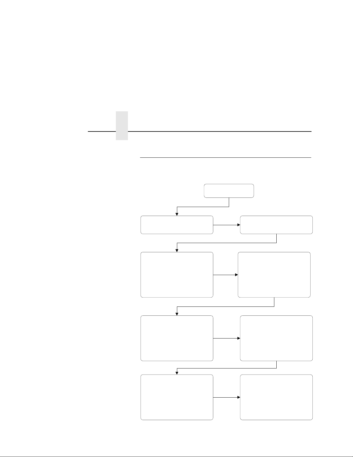
Chapter 2
Edge Determination
Reflectance Minimum <=
Threshold percentage of Reflectance
Maximum
Min. Edge Contrast (worst pair) >=
Min. Edge Contrast Threshold
Symbol Contrast >= Symbol Contrast
Threshold
Grading Scale:
A: >= 70 %
B: >= 55 %
C: >= 40 %
D: >= 20 %
F: < 20 %
Modulation >= Modulation Threshold
Grading Scale:
A: >= 70 %
B: >= 60 %
C: >= 50 %
D: >= 40 %
F: < 40 %
Defects <= Defects Threshold
Grading Scale:
A: <= 15 %
B: <= 20 %
C: <= 25 %
D: <= 30 %
F: > 30 %
Decodeability >= Decodeability
Threshold
Grading Scale:
A: >= 62 %
B: >= 50 %
C: >= 37 %
D: >= 25 %
F: < 25 %
Percent Decode >= Percent Decode
Threshold
Overall Grade >= Overall Grade
Threshold
Grading Scale:
A: 3.5 to 4.0
B: 2.5 to 3.4
C: 1.5 to 2.4
D: 0.5 to 1.4
F: 0.0 to 0.4
Configuring the Validator
General Process for Barc ode Analysis
The following flow chart is an overview of how the validator
performs the barcode analysis.
84
Figure 26. Barcode Analysis Flowchart
Page 85

Operation
Print Speed Limits
There are a number of factors which contribute to successful bar
code validation, including printer speed, on-demand print settings,
calibration, and ambient light. The following sections describe how
to ensure your bar code validator is scanning and reporting
properly.
Print Speed Limit s
Two factors in the validation process affect the printer’s speed limit:
minimum code height (bar code height) and minimum code gap.
The printer automatically examines the Min. Code Height and Min.
Code Gap values and sets the defined maximum slew (vertical
paper movement) and print speeds to insure proper operation. If
the current Print Speed and/or Slew Speed values in the MEDIA
CONTROL menu are higher than the newly defined maximum, the
values are changed to equal the maximum. If the current values are
lower than the newly defined maximum, no change in speed
occurs.
Min. Code Height (Bar Code Heigh t)
The validator cannot function at the highest speed possible by the
printer. It requires a minimum number of scans per bar code to
make a reliable assessment, so the speed of the printer is limited
by the height of the bar code. If the bar code is very short, printing
needs to be slowed down to allow sufficient scans to occur. If the
print speed exceeds this limit, the message Speed Exceeds
Validator Limit will display. Print speed will be lowered automatically
if required, but will not automatically reset to a higher speed.
The printer cannot predict how high all the bar codes in a given job
will be, so it cannot automatically limit or adjust the print speed to
insure the code height/speed requirement is being met. When the
bar code is too short for the selected speed, the printer produces a
missing bar code error condition. Therefore, printer speed must be
set manually to compensate for bar code height.
85
Page 86

Chapter 2
Bar Code Height In Inches
0.030
Maximum Printer Speed In
Inches Per Second
=
.
.
.
.
.
.
.
.
.
.
.
.
Operation
Use this formula to determine printer speed in relation to bar code
height:
NOTE:
By changing the Min. Code Height, the printer and slew speeds will
be changed automatically.
To change the Min. Code Height:
1. Press to take the printer offline and place the printer in
2. If necessary, press ↓ and ↵ at the same time to unlock the
3. Press until VALIDATOR displays.
4. Press ↓ until Min. Code Height displays.
5. Press + or – to scroll through the choices: 0.13 to 1.00 inches in
6. Press ↵ to select the desired value. The printing and slew
7. Press ↓ and ↵ at the same time to lock the ↵ key, then press
8. Press
To set the printer speed manually:
1. Press to take the printer offline and place the printer in
2. If necessary, press ↓ and ↵ at the same time to unlock the
3. Press until MEDIA CONTROL displays.
4. Press ↓ until Print Speed displays.
5. Press + or – to scroll through the choices.
6. Press ↵ to select the desired value.
7. Press ↓ and ↵ at the same time to lock the ↵ key, then press
8. Press
86
Set Min. Code Height to the height of the shortest bar code
on the label.
Menu mode.
↵
key.
0.01 inch increments. The default is 0.30 inches.
speeds will be changed after
PAUSE
to take the printer offline.
PAUSE
again to put the printer online.
↵
is pressed.
Menu mode.
↵
key.
PAUSE
to take the printer offline.
PAUSE
again to put the printer online.
Page 87
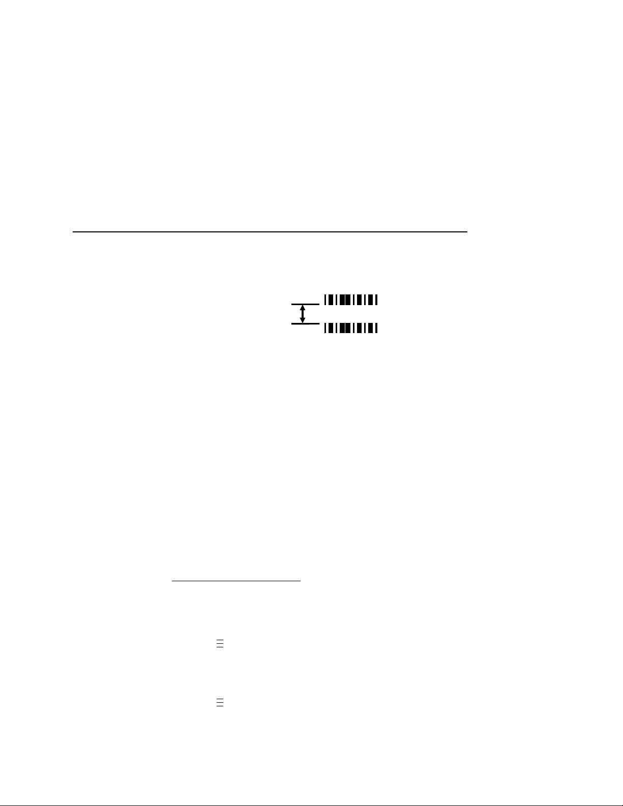
Print Speed Limits
Min. Code Gap
Distance from the
bottom of a bar code to the
top of the next bar code
Next bar code
Bar code
Min. Code Gap In Inches
0.050
Maximum Printer Speed In
Inches Per Second
=
.
.
.
.
.
.
Min. Code Gap
Minimum Code Gap represents the distance between the closest
bar codes within a print job. The distance is measured from the
bottom of one bar code to the top of the next bar code. The closest
bar codes can be located on two separate labels or on the same
label.
This distance is important because it affects how fast the Print
Speed can be set. If the bottom-most bar code on one label is very
close to the top-most bar code on the next label, the printer could
have trouble distinguishing which bar code correlates with which
label. To avoid the risk of miscorrelation, the printer automatically
set its Print Speed.
The default is 0.30 inches. The range is 0.15 to 1.00 inches in 0.01
inch increments.
Use this formula to determine printer speed in relation to minimum
code gap:
To change the Min. Code Gap:
1. Press to take the printer offline and place the printer in
Menu mode.
2. If necessary, press ↓ and ↵ at the same time to unlock the
↵
key.
3. Press until VALIDATOR displays.
4. Press ↓ until Min. Code Gap displays.
5. Press + or – to scroll through the choices: 0.15 to 1.00 inches in
0.01 inch increments. The default is 0.30 inches.
6. Press ↵ to select the desired value.
87
Page 88

Chapter 2
Operation
7. Press ↓ and ↵ at the same time to lock the ↵ key, then press
PAUSE
to take the printer offline.
8. Press
NOTE:
PAUSE
To avoid the risk of miscorrelation, the printer automatically
sets its Print Speed based on the information that has been
selected to ensure validation results are accurate.
again to put the printer online.
On-Demand Printing
In order for each bar code to be successfully validated, the entire
bar code must pass completely under the scanning beam, even
when the printer is set up for on-demand printing. In cases where
the bar code is close to the bottom of a label and the printer is in an
on-demand printing mode, the printer automatically pushes the
label past the scanning beam. Once the bar code is validated, the
printer retracts the label back to be cut or torn off.
Because the printer has to push out and then retract labels in
on-demand printing modes, the extra movements slow the printing
process. You can avoid this by adjusting the form so that the bar
code appears early enough on the form so that it will pass
completely under the scanning beam during normal printing. This
may involve rotating the form or moving the bar code to a different
position on the form.
88
Page 89

Bar Code Failures
The validator tells the printer to announce a fault condition in two
situations:
•
if the validator detects a bad bar code
•
if the validator detects no bar code where it expects to find one.
How the printer reacts to these faults is determined by the printer’s
configuration settings, as described below.
Bad Bar Code Error Detection
The validator examines every bar code that passes under the
scanning beam and sends an analysis report to the printer. If a bar
code is reported to have failed to meet any of the acceptance
criteria, an error condition is reported. How the printer then reacts is
described in “Validator Action (Error Action)” on page 90.
Missing Bar Code Error De tection
Bad Bar Co de Error Detection
A bar code may print so poorly that the validator cannot detect it,
and the printer does not receive an analysis report for the code. To
catch this problem, the printer tracks the position of the last label
printed and knows when it should have completely passed the
scanning beam. It can then compare the number of bar code
analysis reports it expected to the number it received. If the printer
does not receive enough bar code reports, it enters an error
condition. How the printer then reacts is described in “Validator
Action (Error Action)” on page 90.
The number of bar codes expected is determined one of two ways:
•
If Auto is selected for the Number of Codes parameter, and you
are using LinePrinter Plus
IPDS™ graphics software, the printer compares the number of
bar code commands it receives from the software to the
number of analysis reports it receives from the validator.
•
You can set the number of bar codes generated by a
bitmapped image that the printer should expect per form by
selecting a value in the Number of Codes parameter.
®
, IGP®/PGL®, IGP Code V™, or
89
Page 90

Chapter 2
.
.
.
.
.
.
Bar Code Failures
For more information on choosing a value for the Number of Codes
parameter, see “Setting Number of Bar Codes on a Form” on
page 59.
V alidat or Action (Error Action)
The printer response is the same whether the error stems from a
bad or missing bar code. It is determined by the Validator Action
setting in the VALIDATOR menu:
1. Press to take the printer offline and place the printer in
Menu mode.
2. If necessary, press ↓ and ↵ at the same time to unlock the
↵
key.
3. Press until VALIDATOR displays.
4. Press ↓ until Validator Action displays.
5. Press + or – to scroll through the choices:
• Retry Form
• Stop & Retry
(default)
• Grade&Report
• Rescan Form
• Rescan&Retry
• Rescan&Stop
• Stop
• Overstrike
These options are described in detail below.
6. Press ↵ to select the desired value.
7. Press ↓ and ↵ at the same time to lock the ↵ key, then press
PAUSE
8. Press
to take the printer offline.
PAUSE
again to put the printer online.
90
Page 91

Validator Action (Error Action)
Forms Printed After an Error Detection
Because of physical differences between the location of the
printhead and the scanning beam, one or more forms may print after
a bad form (a form with a bar code error that the validator detected).
The number of forms printed after a bad form depends on the Label
Length, Print Speed, and Slew Speed settings in the MEDIA
CONTROL menu. Shorter forms and faster speeds tend to increase
the number of forms printed before the validator has a chance to
detect an error. Also, the validator may not detect an error on forms
that have bar codes near the bottom of the form until the next form
has already started printing.
Forms that print after a bad form are treated differently, depending
upon the error action mode selected (see Table 5). Modes that
require a reprint operation may need to reprint more than just the
bad form.
Table 5. Actions Done to Forms That Print After A Bad Form
Error Action
Mode
Stop Tagged as failed, even though it was never
scanned.
Overstrike Overstruck.
Retry Form Overstruck and reprinted (default).
Stop & Retry Reprinted.
Grade&Report Not applicable (all forms are scanned once).
Rescan Form Scanned. If error persists, it will be rescanned
and overstruck.
Rescan&Retry Scanned. If error persists, it will be overstruck
and reprinted.
Rescan&Stop Scanned. If error persists, it will be tagged as
failed, even though it was never scanned.
Action
91
Page 92

Chapter 2
Bar Code Failures
Stop
If the validator detects a bar code failure, the print job stops, the
printer status indicator lamp
appropriate error message displays.
The printer remains in a fault condition until you press the PAUSE
key. This clears the error message and takes the printer offline. You
must correct any condition that may have caused the fault. When
ready, the printer can be put back online and it will resume printing
with the form immediately following the bad form and any other
forms printed prior to the physical stop (see “Forms Printed After an
Error Detection” on page 91).
flashes, the alarm sounds, and the
Overstrike
Use Overstrike mode when you want bad labels to be marked, but
not reprinted (i.e., when using pre-numbered labels).
If the system detects a bar code failure, the print job stops, the
printer status indicator lamp
appropriate error message displays.
Without pausing, the printer then automatically reverses to the top
of the bad form. It then prints an obliterating pattern over the bad
form and any other forms printed prior to the physical stop (see
“Forms Printed After an Error Detection” on page 91). By default,
the obliterating pattern is a grid of fine lines which clearly marks the
label as bad but allows you to read what was originally printed.
flashes, the alarm sounds, and the
IMPORTANT
92
In the VALIDATOR menu, the Overstrike Style options are: Grid,
Grey, Checkerboard, or Error Type Msg.
NOTE:
If you are using an RFID encoder, set the validator Overstrike
Style different than the RFID Overstrike Style (in the RFID
CONTROL menu). This will help you differentiate between a
validator error and an RFID error.
After the overstrike printing, the printer clears the error message
and stops the alarm, then resumes normal printing at the point the
job was stopped.
Select Error Type Message to see the error message
printed on the bad form as the Overstrike Style.
Page 93

Validator Action (Error Action)
If more than one form is overstruck, only the first overstruck form is
lost (the one with the missing or bad bar code), and a separate print
command is required to resend it from the host, if needed. The rest
of the overstruck forms are automatically resent.
Retry Form
This mode is similar to the Overstrike mode, however, instead of
resuming printing where the printer had left off, the printer will
attempt to reprint the bad form.
NOTE:
The printer will stop, indicate an error, and overstrike as described
on page 92. Then it will skip a number of blank labels, depending
on the setting for Skip Labels (see “Setting for Skip Labels” on
page 61). It will then slew to the next top of a blank form and reprint
the bad form and any other overstruck forms (see “Forms Printed
After an Error Detection” on page 91).
Once the Num Retry counter has been exhausted, the print job
stops completely. After you clear the error message, the printer will
print the same label or the next label, depending on the setting for
Max Retry Action (see “Max Retry Action” on page 63).
The number of times the printer will attempt to reprint the
bad form is determined by the Num Retry setting.
“Num Retry” on page 63.
See
Stop & Retry
This mode is similar to the Stop mode: the printer will stop printing
and display the error message. After you clear the error message, it
will then skip a number of blank labels, depending on the setting for
Skip Labels (see “Setting for Skip Labels” on page 61). Then it will
slew to the next top of a blank form and reprint the bad form and
any other forms printed prior to the physical stop (see “Forms
Printed After an Error Detection” on page 91).
NOTE:
The number of times the printer will attempt to reprint the
bad form is determined by the Num Retry setting.
“Num Retry” on page 63.
See
The printer will stop after the specified Num Retry attempts. After
you clear the error message, the printer will print the same label or
the next label, depending on the setting for Max Retry Action (see
“Max Retry Action” on page 63).
93
Page 94

Chapter 2
Bar Code Failures
Grade&Report
In this mode, the entire print job will print uninterrupted. If one or
more errors is detected, the printer status indicator lamp flashes,
the alarm sounds, and the error message “Bar code fails / Job has
errors” displays.
IMPORTANT
The error message lets you know that at least one bad form
printed. To determine which form(s) are bad, you must
manually scan all of them.
The printer remains in a fault condition until you press the PAUSE
key. This clears the error message and takes the printer offline.
Correct any condition that may have caused the fault, then press
PAUSE to place the printer back online.
Rescan Form
This mode is similar to the Retry Form mode, however, instead of
backing up and overstriking the form, the printer will back up and
rescan the bad form and any other forms that have already printed
(see “Forms Printed After an Error Detection” on page 91).
NOTE:
If the printer scans these forms correctly on any of the rescans, it
will continue printing with the next form.
If the printer fails to scan these forms correctly on all of the rescans,
it will overstrike the forms, stop, and indicate an error similar to Stop
mode. After you clear the error message, the printer will skip a
number of blank labels, depending on the setting for Skip Labels
(see “Setting for Skip Labels” on page 61).
The number of times the printer will attempt to rescan the
form and following forms is determined by the Num Rescan
setting.
See “Num Rescan” on page 63.
94
It will then slew to the next top of a blank form and reprint the same
form or go the next form, depending on the setting for Max Retry
Action (see “Max Retry Action” on page 63).
NOTE:
The only difference between Rescan Form and
Rescan&Stop is that when a form still fails after all the
rescans, Rescan Form will overstrike the bad form,
whereas Rescan&Stop will not.
Page 95

Validator Action (Error Action)
Rescan&Retry
This mode is similar to Rescan Form with one exception: after the
printer has rescanned the form and overstruck it if there was still a
fault, it will reprint and rescan the same form again.
NOTE:
If the printer scans these forms correctly on any of the rescans or
reprints, it will continue printing with the next form.
If the printer fails to scan these forms correctly on all of the rescans
and reprints, it will overstrike the forms, stop, and indicate an error
similar to Stop mode. After you clear the error message, the printer
will skip a number of blank labels, depending on the setting for Skip
Labels (see “Setting for Skip Labels” on page 61).
It will then slew to the next top of a blank form and reprint the same
form or go the next form, depending on the setting for Max Retry
Action (see “Max Retry Action” on page 63).
The number of times the printer will attempt to
form is determined by the Num Rescan setting.
Rescan” on page 63.
The number of times the printer will attempt to
bad form is determined by the Num Retry setting.
“Num Retry” on page 63.
rescan
See “Num
reprint
the
the
See
Rescan&Stop
This mode is similar to the Retry Form mode, however, instead of
backing up and overstriking the form, the printer will back up and
rescan the bad form and any other forms that have already printed
(see “Forms Printed After an Error Detection” on page 91).
NOTE:
If the printer scans these forms correctly on any of the rescans, it
will continue printing with the next form.
If the printer fails to scan these forms correctly on all of the rescans,
it will stop and indicate an error similar to Stop mode. After you
clear the error message, the printer will skip a number of blank
labels, depending on the setting for Skip Labels (see “Setting for
Skip Labels” on page 61).
The number of times the printer will attempt to rescan the
form and following forms is determined by the Num Rescan
setting.
See “Num Rescan” on page 63.
95
Page 96
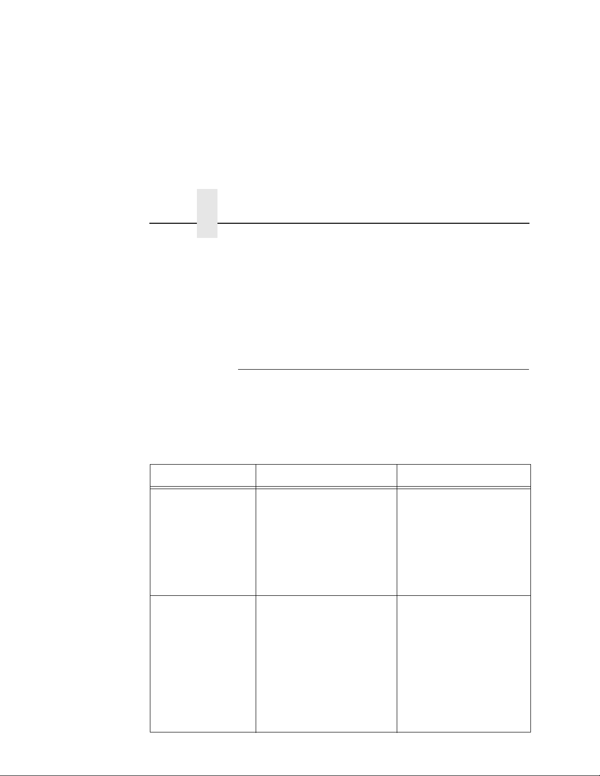
Chapter 2
Bar Code Failures
It will then slew to the next top of a blank form and reprint the same
form or go to the next form, depending on the setting for Max Retry
Action (see “Max Retry Action” on page 63).
NOTE:
The only difference between Rescan Form and
Rescan&Stop is that when a form still fails after all the
rescans, Rescan Form will overstrike the bad form,
whereas Rescan&Stop will not.
Error Messages
The validator can detect a number of errors. When one of these
errors occurs, the validator alerts the printer to perform the currently
selected error action (see “Validator Action (Error Action)” on
page 90) and show the appropriate error message on the printer
display. Validator error messages are explained in Table 6.
Table 6. Message List
Message Explanation Solution
Bar code fails
Job has errors
This message appears when
at least one label in a batch of
labels has a data validation
error.
NOTE:
This message appears only
when Validator Action is set to
Grade&Report.
1. Press
the message.
2. Manually scan all the
bar codes in the label
batch, then reprint the
bad labels.
PAUSE
to clear
Bar Code Improper
Data Format
96
Data validation error: the bar
code is not properly encoded.
For example, a check sum is
incorrect, a required number
of characters is not met, or
the required terminator
characters are not included.
This problem is almost
always caused by incorrect
form or host application
design.
Fix the application so it
sends data in the correct
bar code format.
Page 97
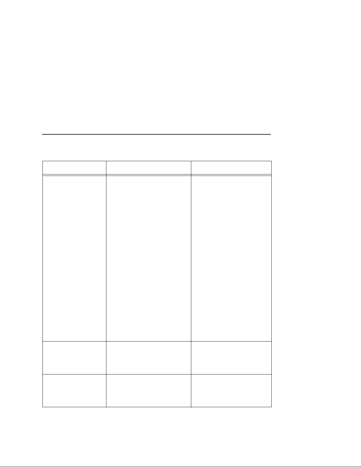
Error Messages
Table 6. Message List
Message Explanation Solution
Bar code quiet
zone too small
Calibration
warning
Data validation error: the
blank zone(s) left or right of
the bar code is not big
enough to meet the minimum
requirement.
Typically, this occurs in forms
where bar codes are placed
too close to other elements,
the bar code is too close to an
edge of the media, or the
media’s position is shifting.
The minimum quiet zone on
each end of the bar code
should be ten times the
minimum element width or
1/4 inch, whichever is greater.
In addition, between bar
codes, the validator requires
a minimum distance of 20
times the minimum element
width or 1/2 inch, whichever is
greater.
The validator has detected
that it needs calibration. This
message is a reminder and
does not halt printing.
1. Fix the application.
2. Disable Quiet Zone in
the VALIDATOR menu.
Press
PAUSE
message. Calibrate the
validator. See “Calibration”
on page 42.
to clear the
Checksum Failure The bar code data fails the
checksum check or is missing
the checksum digit.
Verify that the checksum
digit exists in the bar code
and that it is the correct
value.
97
Page 98
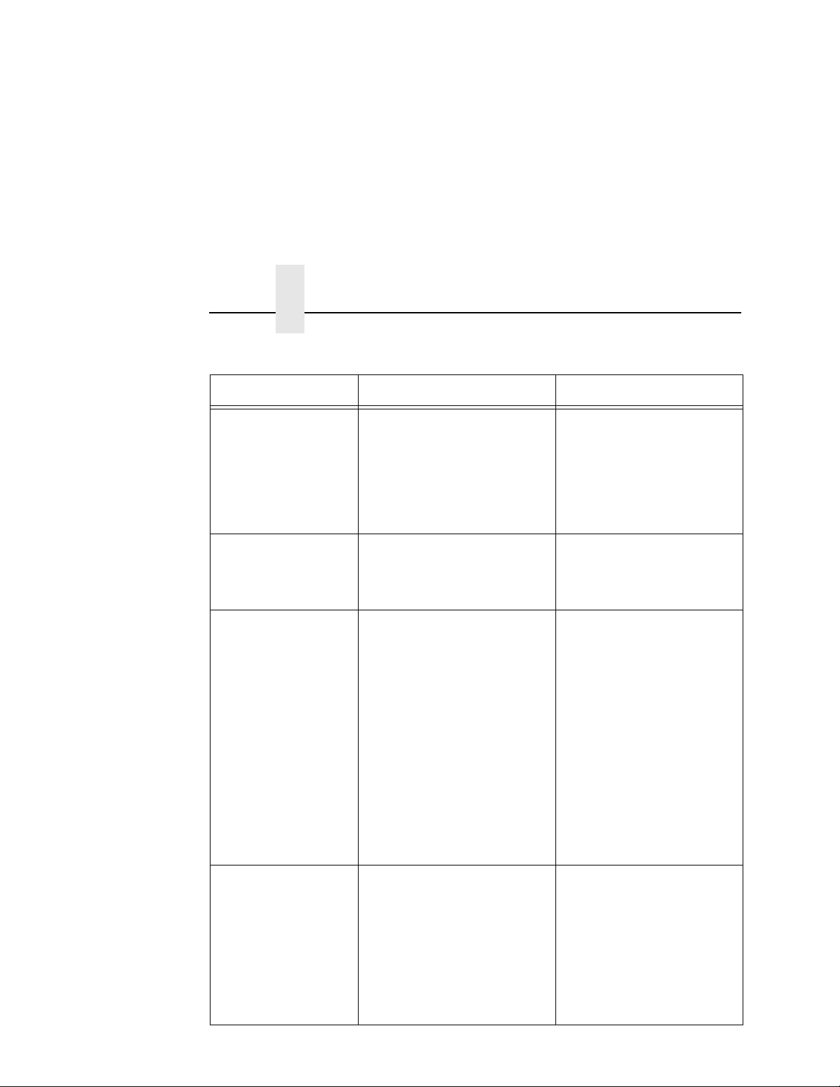
Chapter 2
Message Explanation Solution
Bar Code Failures
Table 6. Message List
Contrast too low
Check media
ODV COMM ERR
See Manual
Overall Grade
Fail
Data validation error: the
contrast between bars and
spaces is not sufficient. This
can be caused by too little
heat in the thermal transfer or
by use of colored media or
ribbons.
Communication error
between printer and online
data validator (ODV).
Overall data validation failure:
decodeability, percent
decode, defects, modulation,
EC Min, Rmin, and/or Symbol
Contrast.
Increase Print Intensity or
reduce Print Speed in the
QUICK SETUP menu or via
host software, change
media, or set Symbol
Contrast = 0% (to disable it)
in the VALIDATOR menu.
Cycle power. If the problem
persists, contact your
authorized customer service
representative.
1. Press
2. Adjust the parameter
3. Lower the Overall
PAUSE
the message.
that is causing the
failure. To see which
parameter is failing, run
a Scan Report
(page 74).
Grade to a point where
the worst parameter
grade will be above the
Overall Grade
threshold.
to clear
Poor scanning
Check heat&head
98
Data validation failure:
decodeability. The difference
between wide and narrow
elements is too close for the
validator to reliably discern.
This usually indicates an
improperly set heat/speed/
pressure combination or the
loss of a printhead element.
1. Adjust Print Intensity
and Print Speed in the
QUICK SETUP menu or
via host software.
2. Adjust the printhead
pressure. (Refer to the
User’s Manual
.)
Page 99
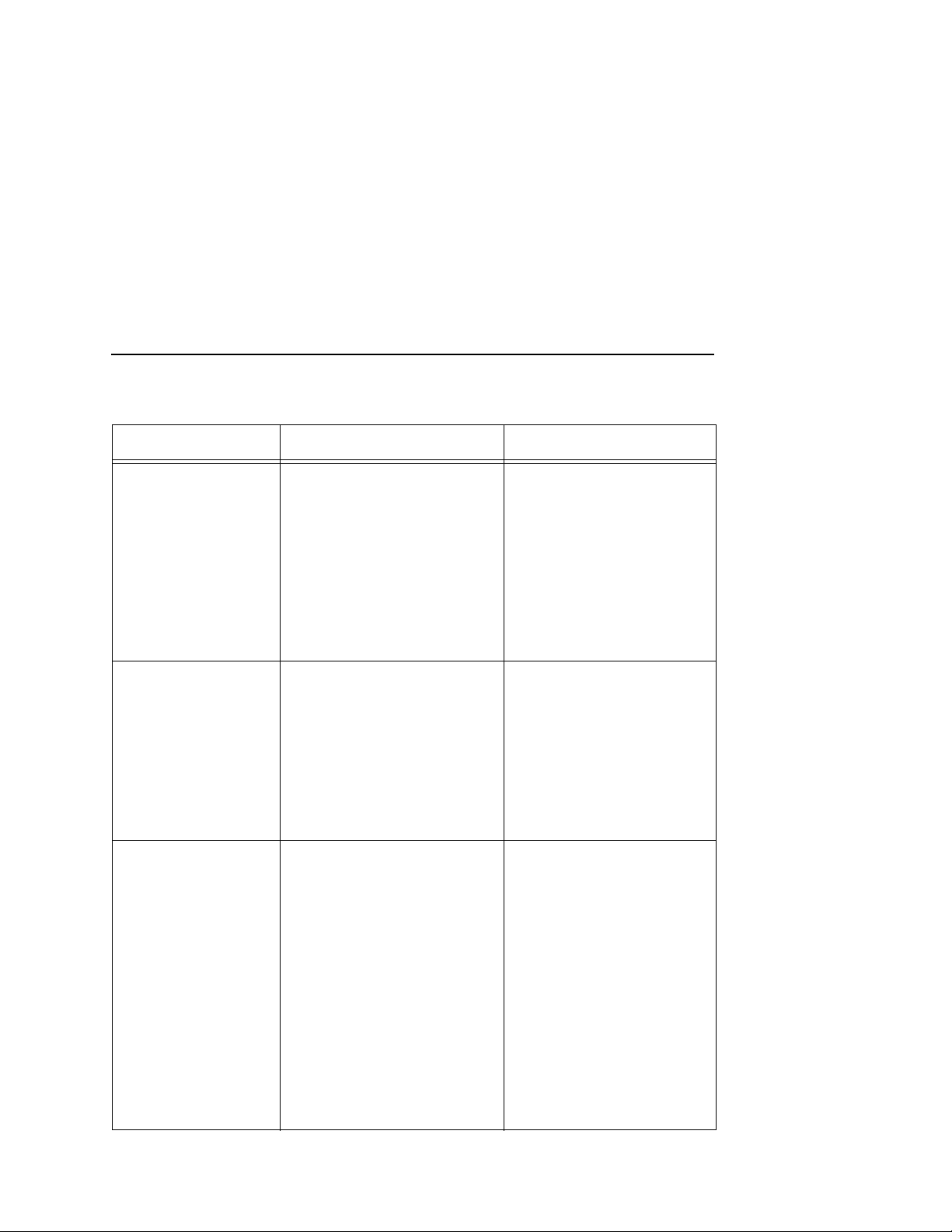
Error Messages
Table 6. Message List
Message Explanation Solution
Poor scanning
Check media
Poor scanning
Inspect head
Speed Exceeds
Validator Limit
Data validation failure:
percent decode. The validator
detected gross
inconsistencies within the
height of the bar code. These
types of failures are likely
attributed to large blemishes
within the bar code, caused
by ribbon wrinkle or debris on
media.
Data validation failure:
hardware defect. The
validator detected
unexpected dark spots in
spaces or light spots in bars.
This usually indicates a poor
ribbon/media combination, a
dirty printhead, or a burned
pixel.
Print Speed is set above the
maximum allowed for bar
code printing by the validator
as the Power-Up
configuration with the
validator option installed.
An attempt was made to set
Print Speed above the
maximum allowed in the
QUICK SETUP menu or via
host software.
Maximum speed depends on
Min. Code Height and Min.
Code Gap.
1. Check for a wrinkled
ribbon or debris on
media. Roll wrinkled
area onto take-up
spindle.
2. Adjust the printhead
pressure blocks. (Refer
to the
User’s Manual
1. Check that paper and
ribbon are clean,
unwrinkled, and
installed correctly.
2. Clean the printhead.
3. If message reappears,
replace the printhead.
This message only appears
briefly, and the speed is
automatically reduced.
Make sure Min. Code
Height (page 85) and Min.
Code Gap (page 87) are set
correctly.
.)
99
Page 100
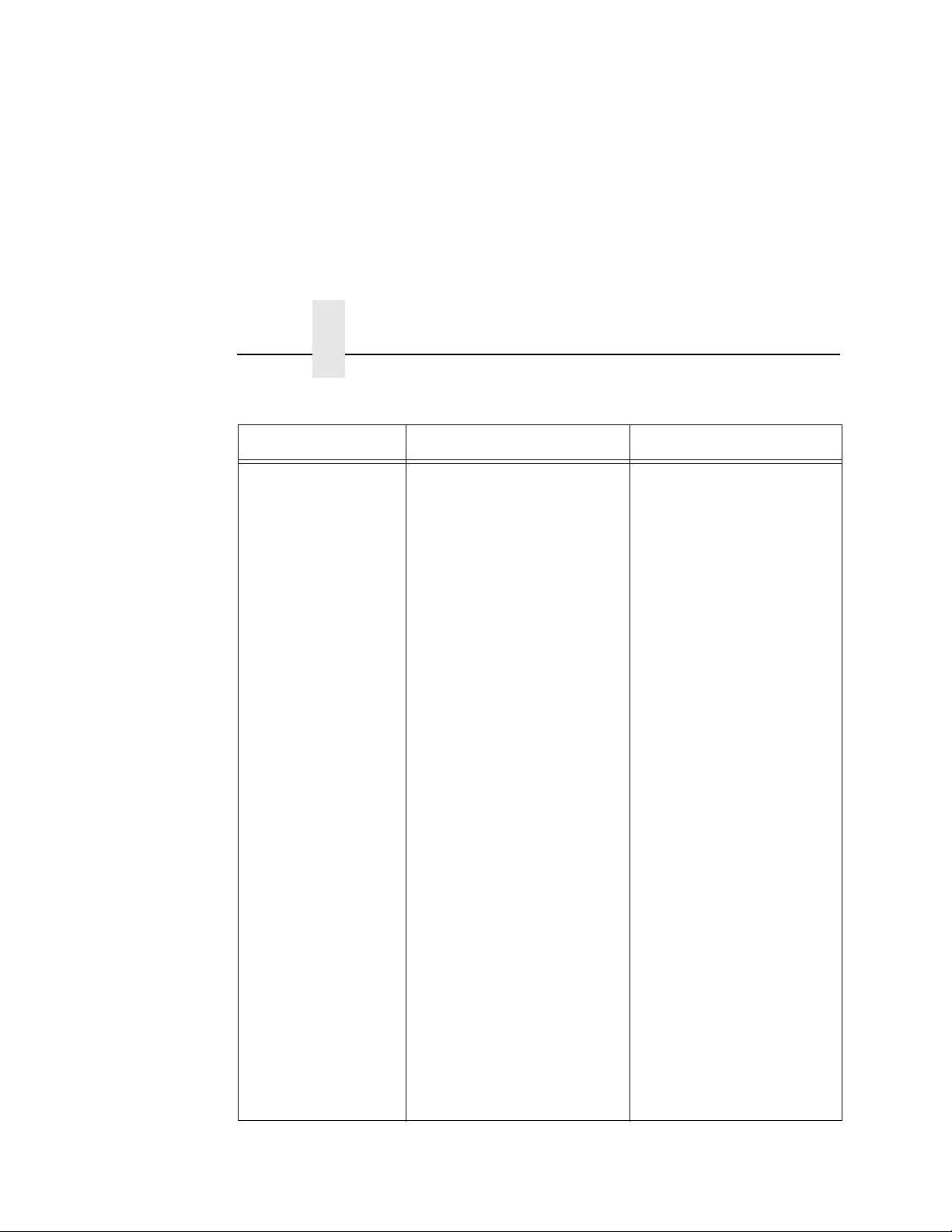
Chapter 2
Message Explanation Solution
Bar Code Failures
Table 6. Message List
Unscannable:
xx Missing Codes
Data validation error: missing
bar code. An expected bar
code is missing or was
printed so poorly that the
validator cannot detect it.
xx = number of bar codes
missing on the form that
caused the error.
1. Check that paper and
ribbon are clean,
unwrinkled, and
installed correctly.
2. Run a print job and
check that the validator
beam is not obstructed;
remove obstructions as
necessary.
3. Run a print job and
check that the READ
LED flashes as bar
codes exit the printer. If
the READ LED does not
flash, cycle power and
run the job again. If the
READ LED does not
flash, inspect the cables
and the cable
connections. If the
cables are undamaged
and the connections are
good, replace the
validator.
100
4. If using bitmapped bar
codes, set Number of
Codes (page 59) to the
number of codes per
form (not Auto).
5. Adjust Print Intensity
and Print Speed in the
QUICK SETUP menu or
via host software.
 Loading...