

Page 1

Page 2

READ THIS SOFTWARE LICENSE AGREEMENT BEFORE USING THIS PRINTER
Software License Agreement
CAREFULLY READ THE FOLLOWING TERMS AND
CONDITIONS BEFORE USING THIS PRINTER. USING THIS
PRINTER INDICATES YOUR ACCEPTANCE OF THESE TERMS
AND CONDITIONS. IF YOU DO NOT AGREE TO THESE TERMS
AND CONDITIONS, PROMPTLY RETURN THE PRINTER AND
ALL ACCOMPANYING HARDWARE AND WRITTEN MATERIALS
TO THE PLACE YOU OBTAINED THEM, AND YOUR MONEY
WILL BE REFUNDED.
Definitions
“Software” shall mean the digitally encoded, machine-readable
data and program. The term “Software Product” includes the
Software resident in the printer and its documentation. The
Software Product is licensed (not sold) to you, and Printronix, Inc.
either owns or licenses from other vendors who own, all copyright,
trade secret, patent and other proprietary rights in the Software
Product.
License
1. Authorized Use. You agree to accept a non-exclusive license
to use the Software resident in the printer solely for your own
customary business or personal purposes.
2. Restrictions.
a. To protect the proprietary rights of Printronix, Inc., you
agree to maintain the Software Product and other
proprietary information concerning the typefaces in
strict confidence.
b. You agree not to duplicate or copy the Software
Product.
c. You shall not sublicense, sell, lease, or otherwise
transfer all or any portion of the Software Product
separate from the printer, without the prior written
consent of Printronix, Inc.
d. You may not modify or prepare derivative works of the
Software Product.
e. You may not transmit the Software Product over a
network, by telephone, or electronically using any
means; or reverse engineer, decompile or disassemble
the Software.
f. You agree to keep confidential and use your best
efforts to prevent and protect the contents of the
Software Product from unauthorized disclosure or use.
3. Transfer. You may transfer the Software Product with the
printer, but only if the recipient agrees to accept the terms
and conditions of this Agreement. Your license is
automatically terminated if you transfer the Software Product
and printer.
Limited Software Product Warranty
Printronix, Inc. warrants that for ninety (90) days after delivery, the
Software will perform in accordance with specifications published
by Printronix, Inc. Printronix, Inc. does not warrant that the
Software is free from all bugs, errors and omissions.
Remedy
Your exclusive remedy and the sole liability of Printronix, Inc. in
connection with the Software is replacement of defective software
with a copy of the same version and revision level.
Disclaimer of Warranties and Limitation of Remedies
1. THE PARTIES AGREE THAT ALL OTHER WARRANTIES,
EXPRESS OR IMPLIED, INCLUDING WARRANTIES OF
FITNESS FOR A PARTICULAR PURPOSE AND
MERCHANTABILITY ARE EXCLUDED.
Printronix, Inc. does not warrant that the functions contained
in the Software will meet your requirements or that the
operation of the Software will be uninterrupted or error free.
Printronix, Inc. reserves the right to make changes and/or
improvements in the Software without notice at any time.
2. IN NO EVENT WILL PRINTRONIX, INC. BE LIABLE FOR
LOST PROFITS, LOST DATA, BUSINESS
INTERRUPTIONS, OR ANY OTHER DIRECT, INDIRECT,
INCIDENTAL OR CONSEQUENTIAL DAMAGES ARISING
OUT OF THE USE OF OR INABILITY TO USE THIS
PRODUCT, EVEN IF HAS BEEN ADVISED OF THE
POSSIBILITY OF SUCH DAMAGES, OR ANY DAMAGES
CAUSED BY THE ABUSE OR MANIPULATION OF THE
SOFTWARE. SOME STATES DO NOT ALLOW THE
EXCLUSION OR LIMITATION OF LIABILITY FOR
CONSEQUENTIAL OR INCIDENTAL DAMAGES, SO THE
ABOVE LIMITATION MAY NOT APPLY TO YOU.
3. Printronix, Inc. will not be liable for any loss or damage
caused by delay in furnishing a Software Product or any other
performance under this Agreement.
4. Our entire liability and your exclusive remedies for our liability
of any kind (including liability for negligence except liability for
personal injury caused solely by our negligence) for the
Software Product covered by this Agreement and all other
performance or nonperformance by us under or related to this
Agreement are limited to the remedies specified by this
Agreement.
5. California law governs this Agreement.
Termination of License Agreement
This License shall continue until terminated. This license may be
terminated by agreement between you and Printronix, Inc. or by
Printronix, Inc. if you fail to comply with the terms of this License
and such failure is not corrected within thirty (30) days after notice.
When this License is terminated, you shall return to the place you
obtained them, the printer and all copies of the Software and
documentation.
U.S. Government Restricted Rights
Use, duplication or disclosure by the Government is subject to
restrictions as set forth in the Rights in Technical Data and
Computer Software clause at FAR 242.227-7013, subdivision (b)
(3) (ii) or subparagraph (c) (1) (ii), as appropriate. Further use,
duplication or disclosure is subject to restrictions applicable to
restricted rights software as set forth in FAR 52.227-19 (c) (2).
Acknowledgement of Terms and Conditions
YOU ACKNOWLEDGE THAT YOU HAVE READ THIS
AGREEMENT, UNDERSTAND IT, AND AGREE TO BE BOUND
BY ITS TERMS AND CONDITIONS. NEITHER PARTY SHALL BE
BOUND BY ANY STATEMENT OR REPRESENTATION NOT
CONTAINED IN THIS AGREEMENT. NO CHANGE IN THIS
AGREEMENT IS EFFECTIVE UNLESS WRITTEN AND SIGNED
BY PROPERLY AUTHORIZED REPRESENTATIVES OF EACH
PARTY. BY USING THIS PRINTER, YOU AGREE TO ACCEPT
THE TERMS AND CONDITIONS OF THIS AGREEMENT.
Page 3

Network Interface Card
User’s Manual
Page 4

This document contains proprietary information protected by copyright.
No part of this document may be reproduced, copied, translated or
incorporated in any other material in any form or by any means, whether
manual, graphic, electronic, mechanical or otherwise, without the prior
®
written consent of Printronix
.
Printronix makes no representations or warranties of any kind regarding
this material, including, but not limited to, implied warranties of
merchantability and fitness for a particular purpose. Printronix shall not be
held responsible for errors contained herein or any omissions from this
material or for any damages, whether direct or indirect, incidental or
consequential, in connection with the furnishing, distribution,
performance, or use of this material. The information in this manual is
subject to change without notice.
Copyright 2005, Printronix, Inc. All rights reserved.
Page 5

Trademark Acknowledgements
Portions of this manual used by permission of Wyndham Technologies,
Inc. Copyright 1991-1999 Wyndham Technologies Inc.
IGP, LinePrinter Plus, PGL, Network Interface Card, and Printronix are
registered trademarks of Printronix, Inc.
AIX, AS/400, NetView, and OS/2 are registered trademarks, and
AFP, Intelligent Printer Data Stream, IPDS, Print Services Facility,
and PSF are trademarks of International Business Machines
Corporation.
Netscape, Netscape Navigator, and the Netscape Communications logo
are trademarks of Netscape Communications Corporation.
Code V is a trademark of Quality Micro Systems, Inc.
Unix is a registered trademark of X/Open Company Limited.
Microsoft, MS-DOS, Windows, Windows 95, Windows 98, Windows Me,
WIndows NT and Windows 2000 are registered trademarks of Microsoft
Corporation.
Novell and NetWare are registered trademarks of Novell, Inc.
PostScript is a registered trademark of Adobe Systems Inc.
FTP Software and OnNet are trademarks or registered trademarks of
FTP Software, Inc.
NetManage and Chameleon are trademarks or registered trademarks of
NetManage, Inc.
Frontier Technologies and SuperTCP are trademarks or registered
trademarks of Frontier Technologies Corporation.
Solaris is a registered trademark of Sun Microsystems, Inc.
HP-UX is a registered trademark of Hewlett-Packard Company.
DG/UX is a registered trademark of Data General Corporation.
LINUX is a registered trademark of Linus Torvalds.
Ultrix is a registered trademark of Digital Equipment Corporation.
IRIX is a registered trademark of Silicon Graphics, Inc.
Page 6

Page 7

Table of Contents
1 Introduction .............................................. 17
Overview ...............................................................................17
What Is The NIC?.............................................................17
What Special Features Are Available?.............................18
Logical Printer Architecture ...................................................19
Destinations/Queues ........................................................21
Models..............................................................................21
Interfaces...............................................................................23
10/100Base-T...................................................................24
Speed Setting for 10/100Base-T......................................29
Conventions Used In This Manual ........................................30
Notes And Notices.................................................................31
Printronix Customer Support Center .....................................31
2 Installation And Configuration .................. 33
Installation .............................................................................33
Connecting To The Network ............................................33
Configuration Tools ...............................................................34
Configuration Using The Control Panel............................34
NIC Verification ................................................................39
Wireless NIC Configuration Using
The Control Panel ............................................................40
Kerberos Enabled Wireless NIC Configuration ................49
HTML Forms ....................................................................51
Configuration Alternatives ................................................54
Page 8

Table of Contents
3 Embedded NIC Web Page ....................... 55
Overview ...............................................................................55
Configuration .........................................................................56
Network Configuration...........................................................57
TCP/IP Network ...............................................................57
802.11b ............................................................................ 59
Windows Network (NetBIOS TCP/IP) .............................. 61
Novell Network ................................................................. 62
Print Path Configuration ........................................................64
Destination Settings ......................................................... 64
Current Model Settings .................................................... 66
Current Log Path Settings................................................67
Print Model Configuration......................................................68
Log Path Configuration ......................................................... 71
TN5250/3270 Configuration ..................................................73
SNMP Configuration .............................................................77
Administration Configuration ................................................. 85
System Information .......................................................... 85
Passwords .......................................................................88
System Configuration............................................................89
Security Configuration ...........................................................89
Kerberos Configuration .................................................... 89
Credentials Information....................................................91
Status .................................................................................... 91
Status - I/O Port ....................................................................91
Status - Network....................................................................92
Page 9

Table of Contents
4 Windows Configuration ............................ 93
Overview ...............................................................................93
Windows Environment Description........................................93
Windows NIC Configuration ..................................................94
Mandatory ........................................................................94
Optional............................................................................94
Configuration Using ARP .................................................94
Communicating Across Routers.......................................96
Changing Workgroup Names...........................................97
Changing Destination Names ..........................................98
Windows Host Configuration ...............................................100
Windows NT 4.0 Host Setup ..........................................100
Windows XP/2000 Host Setup .......................................104
Windows NT 3.51 Host Setup ........................................114
Windows Me or 9x Host Setup .......................................116
Printronix Printing System (PPS) Host Setup ................117
Windows 3.1 Host Setup ................................................118
Windows Troubleshooting Tips ...........................................119
Technical Support ..........................................................119
NIC Cannot Be Found On The Network.........................120
HTML Configuration Forms Will Not Display..................120
Errors Occur When Defining An LPR Printer .................121
Cannot Browse The NIC On The Network .....................121
Printer Errors When Printing Or No Output ....................122
TCP/IP Access Problem.................................................122
Web Browser/HTTP Problem .........................................124
Windows NT 4.0 Or 2000 Host Setup Problems ............125
Page 10

Table of Contents
5 Unix Configuration .................................. 127
Overview .............................................................................127
Unix Environment Description .............................................127
Unix NIC Configuration .......................................................128
Mandatory ...................................................................... 128
Optional..........................................................................128
Using ARP .....................................................................128
Using RARP ...................................................................130
Using BOOTP ................................................................131
Communicating Across Routers.....................................132
Unix Host Configuration ......................................................133
Manual System V Host Setup ........................................133
NIC Installation on HP-UX...................................................134
Solaris 2.6 – 7 NIC Setup ....................................................135
SCO Setup ..........................................................................136
Manual LPR/LPD Host Setup.........................................143
NIC Configuration for AIX 4............................................144
AIX Remote Queue Time–Out Setting ........................... 146
Printing From AIX...........................................................147
Printing With FTP ........................................................... 147
Direct Socket Printing.....................................................148
Unix Troubleshooting Tips .................................................. 149
NIC Cannot Be Found On The Network......................... 149
Nothing Prints ................................................................150
Stair-Stepped Output .....................................................151
No Form Feed Or Extra Page Comes Out .....................152
TCP/IP Access Problem.................................................152
Front Panel Message – Dynamically Set Params
Read Only ......................................................................154
Page 11

Table of Contents
6 Novell Configuration ............................... 155
Overview .............................................................................155
Novell Environment Description ..........................................155
Novell NIC Configuration.....................................................156
Using HTML Forms ........................................................157
Novell Host Configuration....................................................158
NetWare Version 3.x PSERVER Setup .........................158
NetWare Version 3.x RPRINTER Setup ........................160
NetWare Version 4.x and 5.x PSERVER Setup.............163
NetWare Version 4.x and 5.x RPRINTER Setup ...........166
Novell Troubleshooting Tips ................................................168
NetWare 3.x – No PSERVER Connection .....................169
NetWare 4.x and 5.x- No PSERVER Connection ..........170
7 Novell Configuration For
10/100Base-T IntT6(ll)-80(ion)7.5(uia)-6.3(s)-2m ......................... 5
Page 12

Table of Contents
Referencing A Bindery Queue In NDS
(Netware 3.x, Netware 4.x, And Netware 5.x)................188
RPRINTER/NPRINTER Setup
(Netware 3.x, Netware 4.x, And Netware 5.x)................188
NDPS Configuration (Netware 4.11 And Above) ...........191
Troubleshooting (10/100Base-T) ........................................194
PSERVER Setup ...........................................................194
RPRINTER/NPRINTER Setup .......................................197
Printing Related .............................................................199
8 OS/2 Configuration ................................. 203
Overview .............................................................................203
Configuring The NIC TCP/IP Settings ................................. 203
Mandatory Settings ........................................................ 204
Optional Settings............................................................204
OS/2 Workstation Configuration..........................................204
Using The LPR Command .............................................204
Using An OS/2 LPR Print Queue ...................................205
TCP/IP Access Problem.................................................208
9 z/OS Configuration, IPDS Printer ........... 211
Overview .............................................................................211
Requirements.................................................................211
Configuration Checklist .................................................. 212
Configuring PSF for z/OS to Print IPDS Files ..................... 213
Configuration Procedure ................................................213
Verifying a TCP/IP-Attached Printer on z/OS.................223
Sharing Line Matrix Printers on z/OS ..................................224
JES Spool Printer Sharing .............................................224
Port Switching Printer Sharing .......................................226
Handling z/OS Connectivity Problems ................................226
Ping is Not Successful ...................................................226
Ping is Successful ..........................................................227
Page 13

Table of Contents
10 AS/400 Configuration, ASCII Printer ...... 229
Overview .............................................................................229
Configuring AS/400 For ASCII Using TCP/IP......................231
Configuring With ADDTCPIFC .......................................231
Configuring A Router Definition With ADDTCPRTE ......233
Configuring A Local Domain And Hostname..................233
Configuring A TCP/IP Host Table Entry ......................... 233
Configuring The AS/400 For Printing ..................................234
Setting Up Printing For ASCII Files................................234
Verify Printing On AS/400 ...................................................240
AS/400 ASCII Troubleshooting ...........................................241
TCP/IP Access Problem.................................................242
Web Browser/HTTP Problem .........................................244
11 AS/400 Configuration, IPDS Printer....... 245
Configuring On AS/400 As An IPDS Printer........................245
Printing AFP, IPDS, And SCS Files ...............................245
Requirements.................................................................246
Configuration Checklist ..................................................246
Configuring An AS/400 TCP/IP Interface With
ADDTCPIFC...................................................................248
Configuring PSF/400 For IPDS On V3R2 ......................250
Configuring PSF/400 For IPDS On V3R7 And Above....256
Configuring PSF for IPDS On V4R2 And Above ............261
Configuring AFP with CRTPSFCFG on V4R3 and
Above (Optional) ............................................................262
Configuring PSF with CRTDEVPRT On V4R2 and
Above .............................................................................264
Verifying The IPDS Configuration On AS/400 .....................268
Sharing The AS/400 Printer On The Network .....................269
Printer Sharing Parameters............................................270
Page 14

Table of Contents
AS/400 Troubleshooting......................................................273
Cannot PING The Printer ...............................................273
PSF/400 Terminates When Initialized............................273
Spooled Print File Remains In PND Status ....................274
Spooled Files Disappear Without Printing......................274
Data Is Being Clipped ....................................................274
12 z/OS Configuration, TN3270E................ 275
z/OS Configuration For A TN3270E Printer ........................275
Coax Printer Support FMID .................................................275
Program Materials ...............................................................276
VTAM Definitions For SCS and DSE TN3270E .............277
TCPIP Configuration With TN3270E..............................279
Printer Inventory Manager As Defined With TN3270E... 280
Configuration Screens.........................................................289
13 AS/400 Configuration, TN5250 .............. 293
Setting Up TN5250 Print Queues On AS/400 .....................293
Setting Up A TN5250 Connection/Device Via A
Telnet Session ....................................................................294
User Supplied Values ....................................................295
Using Telnet Commands for TN5250..................................295
Command List ................................................................ 295
Getting Started ............................................................... 296
TN5250 Job Formatting ......................................................297
Font Identifier (FONT) - Help ..............................................299
Page 15

Table of Contents
14 Monitoring Printers ................................. 301
Implementing Printer Management .....................................301
Agent/Manager Model ....................................................301
MIB.................................................................................302
SNMP.............................................................................303
Monitoring Tools..................................................................303
OS/2 TCP/IP ..................................................................303
Monitoring With AIX NetView/6000 ................................304
The Remote Management Software ..............................304
Setting The SNMP Community Name............................304
15 Commands ............................................. 305
Command Shell Overview ...................................................305
npsh Access Methods ....................................................305
Main npsh Command Prefixes .......................................305
Getting Command Help..................................................306
Complete Command List .....................................................307
Store Commands ...........................................................307
Set Commands ..............................................................322
List Commands ..............................................................335
Miscellaneous Commands .............................................339
16 Extra Features........................................ 343
NIC Security ........................................................................343
Users And Passwords ....................................................343
Reset The NIC Password...............................................345
TCP Access Lists ...........................................................347
Printer Monitoring And Logging...........................................349
Printer And Print Job Monitoring ....................................349
Printer Logging Through Logpaths.................................350
Page 16

Table of Contents
Downloading Software Through The
Network Interface Card (NIC) ..............................................351
NIC Naming Schemes.........................................................354
Periodic Ping .......................................................................355
Glossary ................................................. 357
Page 17

1 Introduction
Overview
This chapter introduces you to the Network Interface Card (NIC)
architecture and special features, as well as providing information
on installation and configuration tools.
What Is The NIC?
The NIC allows you to attach printers on a local area network (LAN)
rather than attaching them directly to a host system. Following
simple configuration steps, these peripherals can be
simultaneously shared with users on the network whether you are
using TCP/IP, NetBIOS over TCP/IP, or IPX (Novell
The NIC package contains an Ethernet Interface to attach itself and
the printer to the network. The NIC is supplied in one of four forms:
®
).
• an Ethernet adapter attached to the printer parallel port
• a wireless Ethernet adapter
• an integrated Ethernet card
• an integrated wireless Ethernet card.
Throughout this manual, features specific to each NIC type will be
indicated by the sideheads ADAPTER, WLAN ADAPTER,
ETHERNET, and WLAN.
17
Page 18

Chapter 1 Overview
What Special Features Are Available?
NIC offers an extensive list of features including:
• built-in HTML forms for easy cross-platform configuration
• availability of remote management software
• a detailed and easy-to-use command shell built-in to the
firmware
• multi-level configuration security through passwords,
permission levels, and access lists
• WAN-wide communication access
• numerous printer logging methods (e.g., automatic email) to
record printer errors and usage
• remote management through HTML forms, Telnet sessions,
rsh/rcmd/remsh commands, SNMP, and pre-defined log
methods
• extensive built-in troubleshooting tools
18
• built-in telnet and ping clients
• configurable memory usage by disabling protocols and
destination services
• multiple destinations/queues for versatile printer manipulation
and distinct print setups
• header and trailer strings to instruct printers on font, pitch,
printing, etc.
• flexible naming conventions
• automatic network connection and frame type sensing
• simultaneous printing across all I/O ports and all supported
protocols
• multiple network protocol support
Page 19

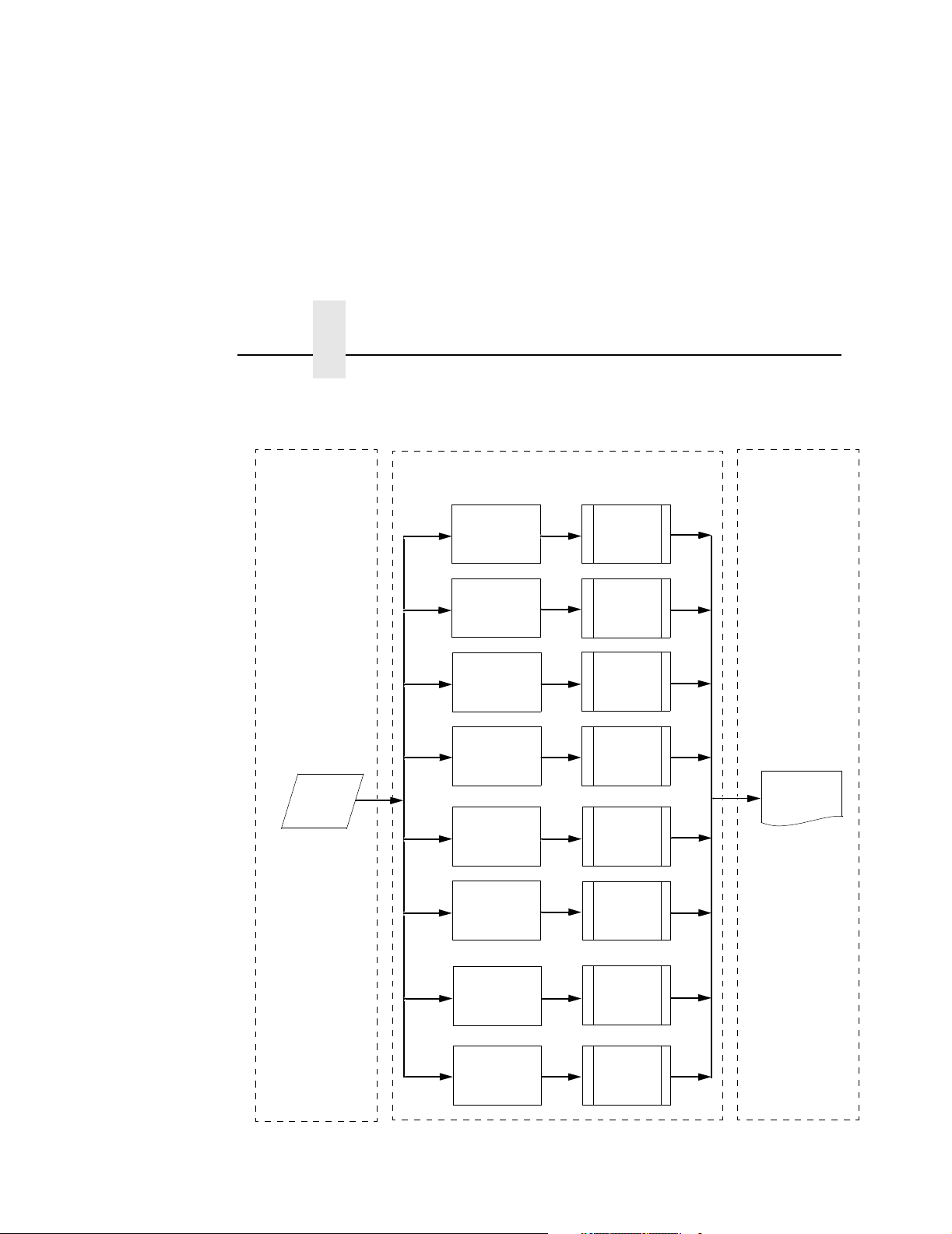
Logical Printer Architecture
The NIC implements a logical printer architecture which gives the
system administrator the possibility to configure the print server to
handle and act upon the print data in several ways. When a print
job comes through the print server, there is a certain logical print
path that it follows before it gets to the printer. Each logical print
path consists of a sequence of logical steps where extra processing
may be performed on the print data before it is sent to the printer.
This ability to preprocess the print data before it is sent to the
printer allows elimination of certain printing problems, or
implementation of printer enhancements that may be difficult and
time consuming to solve or introduce at the system, spool or queue
level. The preprocess ability is also simplistic to perform at the print
server level.
The logical print path for a print job going through NIC consists of
three different phases:
• Phase 1 - the host sends the job to a destination or queue on
NIC (e.g. d1prn).
What Special Features Are Available?
Logical Printer Architecture
• Phase 2 - the print job passes through the associated “model”
(e.g. model “m1”) on NIC for any extra processing associated
with the model.
• Phase 3 - the processed print job is directed to the printer for
output.
19
Page 20
Chapter 1 Logical Printer Architecture
Phase 1 Phase 2 Phase 3
Host
Destination 1
(d1prn)
Destination 2
(d2prn)
Destination 3
(d3prn)
Destination 4
(d4prn)
Destination 5
(d5prn)
Destination 6
(d6prn)
Model 1
(m1)
Model 2
(m2)
Model 3
(m3)
Model 4
(m4)
Printer
Model 5
(m5)
Model 6
(m6)
20
Destination 7
(d7prn)
Destination 8
(d8prn)
Figure 1. Print Path
Model 7
(m7)
Model 8
(m8)
Page 21

Destinations/Queues
Destinations/Queues
For every I/O port on NIC, there is at least one pre-defined logical
print queue or destination to accept print jobs destined for it. This
includes print jobs that are sent directly to the I/O port, such as port
9100. These queue or destination names are pre-defined but can
be changed by the user.
Models
For every destination or queue, there is a pre-defined model
associated with it. The model defines how the print job will be
processed as it passes through to the printer. Models are a set of
mini filters that can be used to modify the print data stream. The
functions available for each model are as follows:
21
Page 22

Chapter 1 Logical Printer Architecture
5. Log one or all of the following information as each print job
passes through the model
• Job ID and username
• User ID and three messages per job about the start and
finish
• Checksum value of the data transferred
• Miscellaneous messages from the printer
• Status of the printer based on the port interface signals
6. Load a specific printer configuration before processing a print
job
• Specify a printer configuration to be associated with a print
queue.
• When a job is set to that print queue, the associated printer
configuration will be loaded before the job is processed.
• Feature allows you to define up to eight unique and
independent printer personalities in a single printer.
22
• Allows you to effectively have eight different printers in one.
Page 23

Interfaces
Interfaces
Models
The NIC interfaces with your printer through an Ethernet
10/100Base-T interface connector.
Two NIC interfaces are available, depending on the type of
controller board the printer contains. Some printers use NICs with
dip switches and LEDs. Other printers use NICs that plug into the
Peripheral Component Interface (PCI) controller boards that have
no dip switches or LEDs.
NOTE: If both cards are present, you will see two sets of front
panel options under network parameter, E-Net Adapter and
Ethernet. The two NICs are two separate interfaces and
are networked. You can autoswitch between the two.
If your NIC does not have dip switches or LEDs refer to
“Speed Setting for 10/100Base-T” on page 29.
23
Page 24
Chapter 1 Interfaces
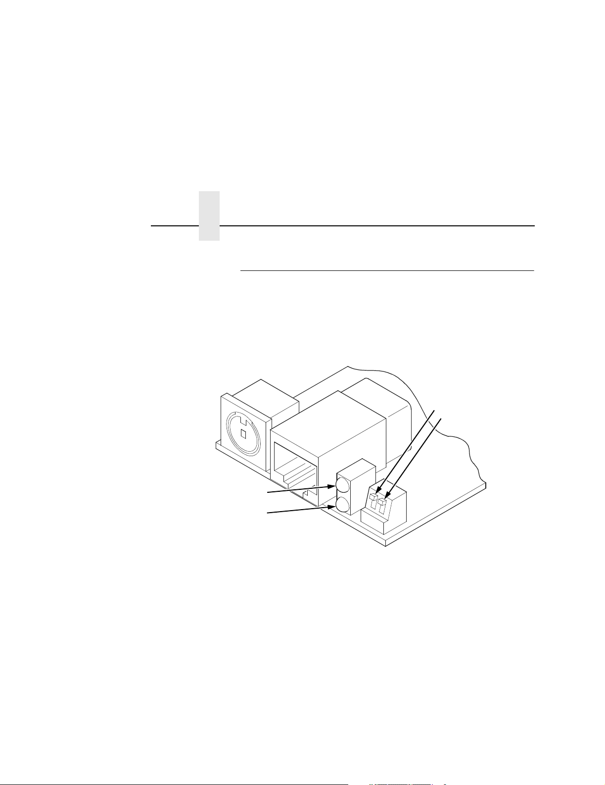
10/100Base-T
ADAPTER
STAT (System Status)
NET (Data to Network)
The NIC at the rear of the printer for the 10/100Base-T interface
has two indicator lights and two DIP switches, as shown in Figure 2.
NOTE: The Wireless NIC DIP switch functionality is the same as
the 10/100Base-T NIC.
DIP Switches
1
2
Figure 2. Status Indicator Lights and DIP Switches
24
Page 25

10/100Base-T
Run and Auto Reset Modes
Run mode is the normal operating state of the NIC. Auto Reset
mode is entered when the watchdog timer is triggered and the Print
Server resets itself. In either mode, the STAT LED flashes at a
varying rate, depending on whether the unit IP address is
configured. The Run Mode and Auto Reset Mode indicator
descriptions are given in Table 1.
Table 1. Run Mode and Auto Reset Mode Indicator Descriptions
STAT Indication Description
OFF flashes on once per second Normal Mode, IP address configured
OFF flashes on two times per
second
ON flashes off once per second Download (MOS)
ON flashes off twice per second Error
IP address not configured
Network Indicator
The NET LED displays the status of the network link. When the
NET LED is on, link integrity is confirmed. The NET LED flashes off
for 1/3 second when a data packet is being transferred. When the
NET LED is off, the network connection has been severed.
Table 2. NET LED Indicator
NET Indication Description
ON constantly Indicates link integrity
ON flashes off 1/3 second Flashes off 1/3 second each time a
packet is transmitted
25
Page 26

Chapter 1 Interfaces
ETHERNET
NET Indication Description
ON flashes Indicates activity
ON constant Indicates that the link is good at 10 Mbps
ON constant Indicates that the link is good at 100 Mbps
Integrated NIC Card LED:
Table 3. Integrated NIC LED Indicator
Wireless Network Indicator
WLAN
ADAPTER
The wireless NIC has 2 bi-color LEDs which can produce three
colors each: green, red, and yellow (green and red combined).
Table 4 shows the STAT LED states for various sytem conditions:
Table 4. Wireless NIC STAT LED States
System Condition STAT LED
26
System is running without an IP
address.
System is running with an IP address. Green, 1 Hz flash
System error. Red 2Hz flash
System is in upgrade mode with an IP
address.
System is in upgrade mode without an
IP address.
Table 5 shows the NET LED states for various network conditions
when a WLAN card is inserted into the wireless NIC. The NIC
(wired) interface will not affect the NET LED while a WLAN card is
present.
Green, 2 Hz flash
Yellow, 1 Hz flash
Yellow, 2 Hz flash
Page 27

Wireless Network Indicator
Table 5. Wireless NIC NET LED States
WLAN Network Condition NET LED
Network-link quality is good Green
Network-link quality is fair Yellow
Network-link quality is bad Red
Network-link not present Off
Network-link present and transmitting Link quality + blink
Table 6 shows the NET LED states for various network conditions
when no WLAN card is found or present.
Table 6. Wireless NIC NET LED States (No WLAN)
10/100Base-T
Wired Ethernet Network Condition
(No WLAN)
Network-link is present Green
Network-link is not present Off
Network-link present and transmitting Blink
NET LED
27
Page 28

Chapter 1 Interfaces
DIP Switches
ADAPTER,
WLAN
ADAPTER
DIP Switch
12
up up Normal operation. With both DIP switches in the “off” position, the
down up Factory default. With the DIP switches in this configuration, the NIC
On the back of the printer, you will find a small window where you
can access two DIP switches labeled 1 and 2 (see Figure 2 on
page 24). The functions of the DIP switches are explained in
Table 7.
NOTE: The DIP switches are not marked with “on” or “off” labels.
Instead, the status of the switch is indicated by its position,
up or down. If the interface card has been installed upside
down (i.e., the DIP switches are to the left of the cable
connector), your DIP switch positions will be reversed and
the settings inverted.
Table 7. 10/100Base-T DIP Switch Settings
Comments
NIC boots up using the settings in flash memory rather than the
default settings.
boots up and all settings stored in flash memory are erased except
the Ethernet address and key value.
up down Default IP. With the DIP switches in this configuration, the NIC boots
up with factory default settings. However, the stored settings in flash
memory are intact. Setting DIP switch 2 to “on” does not clear any
settings stored in flash memory; it boots the unit in a different state
with the settings in flash memory temporarily ignored.
down down Reserved. This DIP switch configuration is not for customer use.
28
Page 29

Speed Setting for 10/100Base-T
Speed Setting for 10/100Base-T
When the router is set to auto-negotiation enable, the following is
the correct behavior of the NIC with each setting:
1. 10mbps Half Duplex
Use parallel detection because the NIC is using force mode
and thus has auto-negotiation disabled.
PORs to 10mbps Half Duplex. Resets to 10mbps Half Duplex.
Reconnection at switch maintains 10mbps Half Duplex.
2. 10mbps Full Duplex
Use parallel detection because the NIC is using force mode
and thus has auto-negotiation disabled.
PORs to 10mbps Full Duplex. Resets to 10mbps Full Duplex.
Reconnection at switch maintains 10mbps Full Duplex.
3. 100mbps Half Duplex
Use parallel detection because the NIC is using force mode
and thus has auto-negotiation disabled.
PORs to 100mbps Half Duplex. Resets to 100mbps Half
Duplex. Reconnection at switch results in 100mbps Half
Duplex.
4. 100mbps Full Duplex
Use parallel detection because the NIC is using force mode
and thus has auto-negotiation disabled.
PORs to 100mbps Full Duplex. Resets to 100mbps Full
Duplex. Reconnection at switch results in 100mbps Full
Duplex.
5. NIC in Auto mode in 100mbps FD environment
Use auto negotiation to the highest common local and remote
capability, i.e. 100FD in this case.
PORs to 100/FD. Resets to 100/FD. Reconnection at switch
remains 100/FD.
29
Page 30

Chapter 1 Conventions Used In This Manual
6. NIC in Auto mode in 10mbps HD environment (determined
using 10hd hub)
Use auto-negotiation to the highest common local and remote
capability, i.e. 100FD in this case.
PORs to 10HD. Resets to 10HD. Reconnection at switch
maintains 10HD.
NOTE: With parallel detection, only speed can be determined. The
duplex mode sets to half duplex.
Conventions Used In This Manual
All uppercase print indicates control panel keys.
Example: Press the CLEAR key, then press the ONLINE key.
Quotation marks (“ “) indicate messages on the Liquid Crystal
Display (LCD).
Example: Press the ONLINE key. “OFFLINE” appears on the LCD.
Command syntax and examples are formatted as follows:
30
• The Courier font in boldface indicates commands that you
type. For example:
At the prompt, type:
ping ftp.CompanyWebsite.com
• Regular Courier font indicates references to command syntax
and output. For example:
The ftp.CompanyWebsite.com site is working properly.
• Variable values are shown in
and in text. For example:
ping ipname
The
ipname is working properly.
italics
in command syntax, output,
Page 31

Speed Setting for 10/100Base-T
Notes And Notices
For your safety and to protect valuable equipment, read and comply
with the notes included in this manual. A description follows:
NOTE: A Note gives you helpful information and tips about printer
operation and maintenance.
Printronix Customer Support Center
The Printronix Customer Support Center offers technical support
with:
• Installation
• Configuration and setup
• Operation and supplies loading
• Specifications of the proper print media, ink transport
assemblies, and ink cartridges
• Answers to post-sale service support questions
Notes And Notices
Call the Printronix Customer Support Center at:
1-714-368-2686 in the Americas
31-24-6489410 in Europe, Middle East, and Africa
65-65484114 in Asia Pacific
or visit the Printronix web page at www.printronix.com
http://www.printronix.com/public/servicessupport/
default.aspx
31
Page 32

Chapter 1 Printronix Customer Support Center
32
Page 33

2 Installation And
Installation
Configuration
The NIC provides an RJ-45 connector for 10/100Base-T (UTP)
networks.
Connecting To The Network
To attach the NIC to a network, plug the network cable into the NIC
connector.
ADAPTER,
WLAN
ADAPTER
Watch the LEDs in the rear of the printer as they cycle through the
power-on self-test. When the test is complete, the STAT LED will
begin to flash.
33
Page 34

Chapter 2 Configuration Tools
Configuration Tools
There are two parts to a NIC setup:
• Configuring the NIC so it can be seen on the network. This
involves network-related settings (e.g., an IP address within
TCP/IP environments) configured through the built-in command
shell, npsh, or from the control panel.
• Configuring a host with a new printer so it knows how to send
data to the NIC. Just being able to see the printer on the
network does not mean you can automatically print to it. A host
has to be told where to send the data.
NOTE: Some network environments do not require any network
settings to be configured on the NIC. However, all network
setups require configuration on the host end.
Configuration Using The Control Panel
You can set NIC settings from the printer control panel.
CAUTION
34
When the printer is first powered on, the message “E-NET
INIT.” displays on the control panel. To prevent a loss of NIC
configuration information, do not change the NIC settings
while this message displays. When the initialization is
complete, the message “E-NET READY” displays, and you can
safely change the NIC settings from the control panel.
1. You can set any of three listed parameters from the printer
control panel. These parameters are located in the Ethernet
Address, Adapter Address, or Wireless Address menu.
2. Power on the printer. The message “E-NET INIT.” appears
when the printer is powered on. Configuration can be done
after the “E-NET READY” message appears.
3. Disable the Power Saver mode before starting this procedure.
Page 35

Configuration Using The Control Panel
4. Always print an E-NET test page before performing any
updates or network configuration using the following steps:
• For P7000 printers:
a. Take the printer offline. When the printer LCD reads
“OFFLINE /QUICK SETUP,” press the up and down arrow
keys simultaneously to unlock the control panel.
b. Press the left arrow until “Diagnostics” appears.
c. Press the down arrow until “Printer Tests” appears.
d. Press the down arrow until “Shift Recycle” appears.
e. Press the left arrow until the following appears for each
type of NIC:
• Adapter Test – External NIC
• Ethernet Test – Integrated NIC
f. Press Enter.
• For P5000 printers:
a. Take the printer offline. When the printer LCD reads
“OFFLINE / CONFIG. CONTROL,” press the up and down
arrow keys simultaneously to unlock the control panel.
b. Press the left arrow until “Diagnostics” appears.
c. Press the down arrow until “Printer Tests” appears.
d. Press the down arrow until “Shift Recycle” appears.
e. Press the left arrow until the following appears for each
type of NIC:
• E-Net Test Page or Adapter Test – External NIC
• Ethernet Test – Integrated NIC
f. Press Enter.
35
Page 36

Chapter 2 Configuration Tools
• For T5000e/SL5000e
a. Take the printer offline. When the printer LCD reads
“OFFLINE,” press the down arrow and ENTER keys
simultaneously to unlock the control panel.
b. Press the “+” key until “Printer Tests” appears. Continue
pressing the “+” key until “Printer Tests/E-Net Test Page”
appears. Press ENTER.
printers:
• For T5000r/SL5000r printers:
a. Take the printer offline. When the printer LCD reads
“OFFLINE,” press the down arrow and ENTER keys
simultaneously to unlock the control panel.
b. Press the “+” key until “Printer Tests” appears. Continue
pressing the “+” key until “Printer Tests/Ethernet Test”
appears. Press ENTER.
• For T4
xxx
printers:
a. Take the printer offline. When the printer LCD reads
“OFFLINE,” press the down arrow and ENTER keys
simultaneously to unlock the control panel.
b. Press the NEXT key until “DIAGNOSTICS” appears.
Continue pressing the NEXT key until “Printer Tests/
E-Net Test Page” appears. Press ENTER.
36
• For Laser printers:
a. Take the printer offline. When the printer LCD reads
“OFFLINE/CONFIG. CONTROL,” press the up and down
arrow keys simultaneously to unlock the control panel.
b. For L5520 and L5535 printers, press the right arrow until
“TEST PRINT” appears.
For the L1524 printer model, press the right arrow until
“DIAGNOSTICS” appears.
c. Press the down arrow until “Test Patterns” appears.
d. Press PREV to display “E-Net Test Page.” Press ENTER.
Page 37

Configuration Using The Control Panel
5. Verify the current NIC firmware version number.
NOTE: Firmware exists within the NIC and the printer itself. Each
firmware is a separate entity with its own version number.
Please pay close attention to the type of firmware
referenced in the remaining sections of this document.
The NIC version should be 1.1.3 or higher for 10/100Base-T
Ethernet adapters. If the NIC version is current, skip to step 6
below. If the NIC version is not current, you need to update
both the NIC and printer firmware.
If you need to update the printer firmware, you must do so now.
After the update is complete, you must restart this instruction
from the beginning. Your printer’s
instructions for upgrading the printer firmware. The process of
upgrading the printer firmware will automatically upgrade the
NIC firmware to the appropriate level.
User Manual
includes
IMPORTANT
CAUTION
The NIC firmware is updated only when the current printer
firmware is loaded via the network interface. The serial
interface may be used if the NIC adapter was previously
installed. Loading the printer firmware via the printer’s parallel
port will not update the NIC firmware.
Turning off the printer before the firmware update is complete
may permanently damage the NIC adapter.
Updating the printer firmware takes time. Please be patient
and wait for the “E-NET READY” message to display on the
LCD. Do not turn off the printer before it has completed the
firmware download procedure. The LCD will display
“ONLINE / E-NET READY” when the download is complete.
Wait for this message before turning off the printer.
6. From the front panel, navigate to the IP Address and Netmask
(Subnet Mask) menu options and enter the appropriate values.
Do not enter the Gateway Address at this point. You must
press ENTER after inputting each segment of the IP Address
and Netmask.
37
Page 38

Chapter 2 Configuration Tools
7. Put the printer online and wait for the “E-NET READY”
message to display on the front panel. Placing the printer
online starts the NIC IP Address and Netmask update process.
This process will take several minutes.
NOTE: If you do not put the printer online, the setting you just
entered will not take effect. Do not turn the printer off until
you see the “E-NET READY” message. If you turn the
printer off before the new values are written to memory in
the NIC adapter, you will need to repower the printer and
repeat steps 6 and 7 above immediately.
8. Once the “E-NET READY” message displays, you may enter
the Gateway Address by repeating front panel steps 6 and 7
above. This will ensure the correct Netmask becomes
associated with the Gateway value you enter. From the front
panel navigate to the Gateway Address and enter the
appropriate value. You must press ENTER after inputting each
segment of the Gateway Address.
9. Put the printer online and wait for the “E-NET READY”
message to display on the front panel.
38
10. Enable the Power Saver mode if desired.
NOTE: When the printer is moved from one network to another,
the software cannot find the printer. To solve this problem,
reset the NIC using the dip switches on the back of the
NIC. After resetting the NIC, the software can find the
printer, and the IP address can also be set in the NIC.
See Table 7 on page 28.
Page 39

NIC Verification
NIC Verification
Before performing the verification, you must connect the NIC card
to the network.
1. Print an E-NET test page (following the steps on page 34) to
verify the settings you made.
2. Verify the Netmask is correct in two locations on the E-NET test
page:
• NETWORK INTERFACES
• TCP/IP ROUTING TABLE
The Netmask must be the same in both locations. For example,
if the Netmask is listed as 255.255.255.0 in NETWORK
INTERFACES and is listed as 255.255.255.255 in the TCP/IP
ROUTING TABLE, they do not match and you must correct it
for the Gateway. Also, if a Gateway Address was entered,
verify that “
Gateway Ping Test, where
Address. If a Gateway Address was not entered, the Default
Gateway Ping test is not required and will not display on the
page.
xxx.xxx.xxx.xxx
is alive” is printed under the Default
xxx.xxx.xxx.xxx
is the Gateway
If the Netmask does not match, complete the following steps:
a. Place the printer offline.
b. Using the front panel, modify the Gateway value to 0.0.0.0.
(non-configured).
c. Place the printer online and wait for the “E-NET READY”
message to display.
d. Place the printer offline and enter the Gateway Address
you desire.
e. Place the printer online and wait for the “E-NET READY”
message. This saves the new Gateway Address.
Your NIC is now configured and connected to your network.
39
Page 40

Chapter 2 Configuration Tools
WLAN
ADAPTER,
WLAN
CAUTION
Wireless NIC Configuration Using The Control Panel
NOTE: The Access Point must be configured according to the
manufacturer's installation guide.
To configure Wireless NIC card, configure the ethernet and
wireless IP addresses so they can be seen on the network. This
includes several network-related settings (e.g., an IP address within
TCP/IP environments) configured through the built-in command
shell, npsh, or from the control panel.
IP Address Configuration
You can set the wireless NIC IP settings from the printer control
panel.
When the printer is first powered on, the message “E-NET
INIT” displays on the control panel. This process takes
approximately 1 to 2 minutes. To prevent a loss of NIC
configuration information, do not change the NIC settings
while this message displays. When the initialization is
complete, “E-NET READY” displays, and you can safely
change the NIC settings from the control panel.
40
You need to set both the ethernet and wireless network IP
addresses according to the TCP/IP environment that the printer is
connected to. There are four parameters accessed from the printer
control panel that are IP address related. These parameters are
located in the "Ethernet Address" menu and the "Wireless Address"
menu:
• IP Address
This is the host for IP addresses that have four segments. They are
displayed as SEG1, SEG2, SEG3, and SEG4 which can be set to
any value in the range of 0 to 255.
• Subnet Mask
This is the subnet mask for the host IP that has four segments.
They are displayed as SEG1, SEG2, SEG3, and SEG4 which can
be set to any value in the range of of 0 to 255.
Page 41

Wireless NIC Configuration Using The Control Panel
• Gateway Address
This is the gateway IP addresses that have four segments. They
are displayed as SEG1, SEG2, SEG3, and SEG4 which can be set
to any value in the range of 0 to 255.
• DHCP
The DHCP option allows you to obtain host server IP addresses
when powering onto the network. The DHCP can be configured to:
• Enable – each time you power on, the host server
automatically assigns you a different address (if the IP address
has not been previously assigned).
• Disable – You choose the host server IP address. After the
selection, the IP Address remains fixed even after you reboot.
Wireless Parameter Configuration
Certain "WIRELESS PARAMS" must be configured to match the
Access Point settings:
NOTE: The "ETHERNET PARAMS" are configured the same way
as the 10/100 Ethernet external NIC. Please refer to the
NETWORK SETUP menu in the User’s Manual.
• Signal Strength
This menu displays the strength of the wireless signal.
NOTE: This is a display value only and cannot be changed.
41
Page 42

Chapter 2 Configuration Tools
• Operation Mode
This is the operation mode of the wireless network. The options
include “Infrastructure” and “Ad Hoc” modes. This must match the
Access Point's configuration.
• SSID Name
This is the Service Set Identifier which must be identical to the
Access Point's SSID name. The SSID name can be configured to a
maximum of 32 alphanumeric characters. The SSID name and
alphanumeric characters are divided into three parts in the control
panel menu as "SSID Name (01-15)", "SSID Name (16-30)" and
"SSID Name (31-32)".
NOTE: When two or more consecutive space characters are used
in the SSID, enclose it in a double quoted string;otherwise
upon resetting the NIC, the SSID Name wil be saved in the
Wireless NIC with only one space.
• Min Xfer Rate
Allows you to set the minimum speed at which the Wireless Option
will accept a connection (in million bits per second).
42
This is the wireless transfer rate, and can be set to either “enable”
or “disable.” It is set to “enable” when the operation mode is
"Infrastructure" so that the NIC can automatically detect the optimal
transfer rate. If the operation mode is "Ad Hoc" and the transfer rate
is known, the user can enable or disable the corresponding transfer
rate in the menus "Xfer Rate 1Mb", "Xfer Rate 2Mb", "Xfer Rate
5.5Mb" or "Xfer Rate 11Mb".
• Channel
This is the frequency used for wireless communication. The
2.4GHz band spectrum is divided into different channels (1-15). It is
set to "Default" so that the NIC can detect the correct channel to
communicate with the Access Point in infrastructure mode. If the
operation mode is "Ad Hoc" and the channel is known, the user can
set the corresponding channel in this menu.
Page 43

Wireless NIC Configuration Using The Control Panel
• Ant. Diversity
This is used to select the antenna for communication. It is
recommended to set to "Diverse" for the NIC to detect for optimal
communication. It can also be set to "Primary" or "Auxiliary".
• Preamble
This is the preamble used in the wireless packets. It is
recommended to set to "Default" so that the NIC can detect the
correct preamble. The preamble is approximately 8 bytes of the
packet header generated by the AP is and attached to the packet
prior to transmission. The preamble length is transmission data rate
dependent. The "short" preamble is 50% shorter than the "long"
preamble. Transmit power is 0–100%. It must match the Access
Point's preamble configuration.
• Power Mgmt
This option allows you to set power-save mode and sleep time. A
value specifying the sleep time in milliseconds will be provided. If
set to zero, power-save mode will be disabled.
• Transmit Power
This option allows you to specify the power level used by the
wireless card to send network packets to the access point. Transmit
power is specified as a percentage of full pwer (0 – 100%).
• Internat. Mode
When enabled, the Wireless option adapts to international
frequency requirements in Europe.
• Auth Method
This feature allows the user to select the authentication method
used for the wireless network interface. The options include Open,
Shared, Kerberos, and LEAP.
43
Page 44

Chapter 2 Configuration Tools
• Default WEP Key
The default key must match the Access Point's configuration. If the
Access Point is configured to use "Open System", the default key
should be set to 0. If the Access Point is configured to use 40-bit or
128-bit WEP encryption key, the encryption key must be set to the
same setting as the Access Point's setting. See the following
section on how to set up the encryption key. In addition, there are
four keys (1-4) that an Access Point can use. If the Access Point is
set to use key 1, the default key must be set to 1 to correspond to
the Access Point's setting.
Encryption Key Configuration
As previously mentioned, there are four encryption keys that can be
configured through the control panel. For each encryption key x
(where x can be 1 to 4), the following control menu can be used to
configure the key:
• WEP Key x Format
This is the format of the key. It can be set to either ASCII or
Hexadecimal.
44
• WEP Key x Width
This is the number of bits used for encryption. This can be set to
either 40 Bits or 128 Bits and must match the Access Point's
configuration.
• WEP Key x
This is the key value. If the "WEP Key x Width" is set to 40 Bits, the
key values can be entered in the following 5 sub menus
(BYTE 1, …, BYTE 5). If the "WEP Key x Width" is set to 128 Bits,
the key values can be entered in the following 13 sub menus
(BYTE 1, …, BYTE 13). The key values must configure to match
the corresponding key in the Access Point's key configuration.
Page 45

Wireless NIC Configuration Using The Control Panel
LEAP Parameters
LEAP is a Cisco wireless security scheme. The Cisco LEAP allows
for a WEP key timeout that forces re-authentication, resulting in the
derivation of a new WEP key for the session.
• Auth Method. This feature allows the user to select the
authentication method used for the wireless network interface.
• Open (the default). Selects open authentication.
• Shared. Selects shared key authentication.
• Kerberos. Selects Kerberos authentication (for use when a
Symbol RF card is installed).
• LEAP. Selects LEAP authentication (for use with a Cisco
RF card installed).
• LEAP Username
• LEAP Username (01-15). The first 15 characters of the
LEAP user name (maximum number of characters is 32).
• LEAP Username (16-30). Characters 16 to 30 of the LEAP
user name (maximum number of characters is 32).
• LEAP User (31-32). Characters 31 to 32 of the LEAP user
name (maximum number of characters is 32).
• Reset LEAP User. Resets the LEAP user name to an empty
string.
• LEAP Password
• LEAP Password (01-15). The first 15 characters of the
LEAP password (maximum number of characters is 32).
• LEAP Password (16-30). Characters 16 to 30 of the LEAP
password (maximum number of characters is 32).
• LEAP Password (31-32). Characters 31 to 32 of the LEAP
password (maximum number of characters is 32).
• Reset LEAP Pswd. Resets the LEAP password to an empty
string.
45
Page 46

Chapter 2 Configuration Tools
Kerberos Parameters
Kerberos Enable
• Enable. Enable Kerberos authentication in the wireless
network interface.
• Disable (default). Disable Kerberos authentication in the
wireless network interface.
Kerb. Pwd (01–15)
First 15 characters of the Kerberos password (maximum number of
characters is 40).
Kerb. Pwd (16–30)
Characters 31 to 40 of the Kerberos password (maximum numer of
characters is 40).
Kerb. Pwd (31–40)
46
Characters 31 to 40 of the Kerberos password (maximum number
of characters is 40).
Reset Kerb. Pwd.
Reset Kerberos password to an empty string.
KDC Port Number
KDC (Key Distribution Center) port number is the 2-byte UDP/TCP
port used for Kerberos Communication.
• 88 (default)
• 0–65535
Clock Skew Units
• Seconds (default)
• Minutes
Page 47

Wireless NIC Configuration Using The Control Panel
Clock Skew (SEC)
Sets the maximum allowable amount of time in seconds (SEC) or
minutes (MIN), as specified by the Clock Skew Units, that Kerberos
authentication will tolerate before assuming that a Kerberos
message is invalid.
• Seconds: The range is 60-900, and the default is 300.
• Minutes: The range is 1-15, and the default is 5.
NOTE: Whatever submenu is selected in Clock Skew Units will
display on the Clock Skew (SEC) menu. For example, if
you select Minutes, the Clock Skew (SEC) menu name will
change to Clock Skew (MIN).
Tckt Life Units
Ticket lifetime unit in either seconds, minutes, hours, or days.
• Seconds (default)
• Minutes
• Hours
• Days
Tckt Life (SEC)
Sets the maximum allowable amount of time in seconds (SEC),
minutes (MIN), hours (HR), or days (DAY), as specified by the Tckt
Life Units, that a ticket obtained from the Kerberos server is valid
before getting a new one.
• Seconds: The range is 300-259200, and the default is 43200.
• Minutes: The range is 5-4320, and the default is 720.
• Hours: The range is 1-72, and the default is 12.
• Days: The range is 1-3, and the default is 1.
NOTE: Whatever submenu is selected in Tckt Life Units will
display on the Tckt Life (SEC) menu. For example, if you
select Hours, the Tckt Life (SEC) menu name will change
to Tckt Life (HR).
47
Page 48

Chapter 2 Configuration Tools
Renew Life Units
Renew lifetime unit in either seconds, minutes, hours, or days.
• Seconds (default)
• Minutes
• Hours
• Days
Renew Life (SEC)
Sets the maximum allowable amount of time in seconds (SEC),
minutes (MIN), hours (HR) or days (DAY), as specified by the
Renew Life Units, before warning for a new Kerberos password.
• Seconds: The range is 0-604800, and the default is 0.
• Minutes: The range is 0-10080, and the default is 0.
• Hours: The range is 0-168, and the default is 0.
• Days: The range is 0-7, and the default is 0.
The selected submenu is in Renew Life Units will display on the
Renew Life (SEC) menu. For example, if you select Days, the
Renew Life (SEC) menu name will change to Renew Life (DAY).
48
Equivalent Wireless NIC Configuration Using The
Telnet Command
store ifc 2 wlan ssid <network-name>
store ifc 2 wlan mode adhoc|pseudo|managed
store ifc 2 wlan speed auto|(1 2 5 11)
store ifc 2 wlan channel default|(1-15)
store ifc 2 wlan antenna diverse|primary|aux
store ifc 2 wlan preamble default|long|short
store ifc 2 wlan pmm on|off
store ifc 2 wlan txpwr (0-100)
store ifc 2 wlan opts [[-]openauth][[-]intnl]
Page 49

Kerberos Enabled Wireless NIC Configuration
store ifc 2 wlan defkey disable|(1-4)
store ifc 2 wlan key <key-num> <key-sequence>
store ifc 2 wlan auth <AUTH-METHOD>
store ifc 2 wlan user <AUTH-USER-NAME>
store ifc 2 wlan pass <AUTH-PASSWORD>
Refer to page 307 for the complete command set.
WLAN
ADAPTER,
WLAN
Kerberos Enabled Wireless NIC Configuration
This section provides an example of how a user configures the
Print Server to use the Kerberos authentication via the wired Telnet
session.
This example assumes Symbol’s Access Point and RF card is used
and the Print Server has not been configured for Kerberos
authentication. It also assumes that the KDC, Access Point and the
Print Server are in the same realm.
To set up the Print Server for Kerberos authentication, the
administrator first has to enable Kerberos in the Access Point
according to Symbol’s instructions. Symbol’s Access Point must
have its Network time set up with the correct time server. Once the
Access Point is configured, the Print Server is ready to be
configured for Kerberos authentication.
Configuring the Print Server for Kerberos
Authentication
1. Create a user in the Windows 2000 server that identifies the
Print Server.
NOTE: The user name should be the Print Server’s name. The
password selected will be used as the Kerberos password
and should be set with no expiration.
2. In a secure networked environment, log in as a root user via
Telnet in the wired LAN.
49
Page 50

Chapter 2 Configuration Tools
3. Once logged in, use the Telnet commands to set up the
wireless LAN parameters (e.g. SSID = 103, operating mode =
Infra Structure mode, etc.) that match the Access Point
configuration.
In addition to the normal wireless LAN parameter settings, use
the following commands to enable Kerberos on the wireless
LAN interface and Kerberos for authentication (minimum
settings):
4. Set the wireless LAN interface parameters to enable Kerberos.
store kerberos opts auth
5. Set the Kerberos parameters to enable Kerberos
authentication.
The Kerberos password must match the Windows 2000 user
password for the Print Server. The administrator should choose
at least 9 alphanumeric characters with a combination of upper
and lower case.
The following is a suggestion for creating strong password for
computer security. Make sure the password:
50
• is at least seven characters long. The most secure
passwords are seven to 14 characters long.
• contains characters from each of the following groups:
letters (uppercase and lowercase), numerals, and symbols (all
characters not defined as letters or numerals, i.e., ! @ # $ % ^
& *, etc.)
The kname is default to “krbtgt” which is the default name used in
Windows 2000 KDC. It must be configured to match with the KDC if
the default is changed. The krealm is case sensitive; it must match
the Access Point’s realm.
Page 51

HTML Forms
The SSID of the Print Server must be configured to match the
Access Point’s SSID which also has Kerberos enabled. For
example, if a Windows 2000 user created the password
aBcd-12345 and the Access Point’s realm is set to
REALM.PRINTRONIX.COM, the following telnet commands are
used:
store kerberos password aBcd-12345
store kerberos config krealm REALM.PRINTRONIX.COM
NOTE: If the Kerberos authentication fails, the user will not be able
to Telnet to the Print Server via the wireless LAN interface.
In this case, Telnet to the Print Server via the wired LAN
interface. It should display an error message indicating the
reason for the Kerberos authenticaion failure.
HTML Forms
The NIC settings can be configured over TCP/IP through a
standard Web browser. The NIC Web pages provide a way to
access some of the commands built into the print server.
NOTE: If a router is used, make sure a Gateway value is
configured.
To access the NIC home page:
1. Make sure the print server has an IP address and Subnet Mask
so it is recognizable on your TCP/IP network.
2. Make sure your network station can successfully ping the NIC
over the network.
3. Direct your Web browser to the URL:
http://IPaddress
(e.g., http://192.75.11.9)
where IPaddress is the IP address of your NIC.
NOTE: If you cannot access the web page, refer to “Web Browser/
HTTP Problem” on page 124
51
Page 52

Chapter 2 Configuration Tools
The NIC HTML structure is divided into several menus as shown in
Figure 3.
Index/Home
Configuration
TCP/IP
802.11b
Windows
Novell
Alert Config 1
Alert Config 2
Alert Config 3
Alert Config 4
Alert Config 5
Alert Config 6
Alert Config 7
Alert Config 8
Alert Config 9
Alert Config 10
I/O Port
Network
SNMP
Status
d1prn
d2prn
d3prn
d4prn
d5prn
d6prn
d7prn
d8prn
Help
Print ModelPrint PathNetwork
m1
m2
m3
m4
m5
m6
m7
m8
Administration
About
Log Path
l1
l2
l3
l4
l5
l6
l7
l8
System
1
= Applies only to the Wireless NIC with
TN5250/
d1prn
d2prn
d3prn
d4prn
d5prn
d6prn
d7prn
d8prn
Security
3270
1
Symbol RF cards. It is intended to be used
in infrastructure mode with Kerberos
enabled Symbol Access Point.
52
Figure 3. NIC HTML Structure
NOTE: Online help is available for all HTML pages.
Page 53

HTML Forms
Printer Status Screen
Using the printer IP Address and any standard Web browser, you
can check the status of the printer. Figure 4 shows the exact state
of the printer by showing the printer LCD message. (This screen
automatically refreshes every minute.)
Figure 4. Printer Status Screen
53
Page 54

Chapter 2 Configuration Tools
Configuration Alternatives
Besides the HTML forms and software provided, the NIC internal
command shell, npsh, can also be reached using Telnet, Remote
Shell, and FTP:
Teln et
A TCP/IP command that helps configure NIC settings remotely. A
TCP/IP host starts a Telnet session with the print server and logs
into the device command shell to alter and view settings.
Example:
telnet 192.75.11.9
Remote Shell
A TCP/IP command that helps configure print server settings
remotely. A TCP/IP host uses this command to remotely execute a
single command on the NIC.
Example:
rsh spike list prn
This command remotely executes the npsh command list prn
on the NIC named
spike
.
54
FTP
FTP can also be used to configure print server settings remotely. A
TCP/IP host uses FTP to store a file containing 1 or more NPSH
commands on the FTP file system. The configuration file must be
FTP ‘put’ to the /config/default/defaultCfg file. The configuration file
can later be executed on demand using the ‘load oem’ command
during a telnet (NPSH) session. The configuration file is also
executed automatically during the power-up sequence when DIP
switch 1 is closed.
Page 55

3 Embedded NIC
Overview
Web Page
The NIC comes with an extremely powerful printer management
tool that allows you to monitor, configure, and manage both the
printer and its print job. The NIC comes with an embedded web
server that allows System Administrators and users access to its
printer management capabilities from a standard web browser.
The NIC printer’s IP address is used as a URL, similar to the URL
of an Internet web page. When a web browser is activated and the
printer’s IP address is entered, the printer’s embedded web server
displays its home page, with links to the printer’s status and
configuration settings.
All of NIC's configuration settings are protected by a password so
unauthorized users cannot make changes. When you try to open
any of the NIC 's configuration pages, you are asked for your user
name and password. At the prompt, you need to enter
(unless you have another user configured with root privileges)
followed by the associated password. If there is no password, just
ENTER. For more information on setting passwords, refer to
press
“NIC Security” on page 343.
After you configure the NIC settings, and click the SUBMIT button
on the related form, re-power the NIC to ensure the latest settings
are in use. To reset the NIC, go to the System form under the
Configuration Menu and click the REBOOT button.
root
55
Page 56

Chapter 3 Configuration
The embedded NIC Web server gives you the ability to configure
the network adapter, monitor printer status, and to manage print
jobs. The NIC Web page structure is divided into several menus, as
shown in Figure 3 on page 52
Configuration
The Configuration menu items allow you to configure the settings
for the following items:
• Network - this menu item allows you to change the network
setting for each protocol: TCP/IP, 802.11b, NetBIOS over
TCP/IP, and Netware.
• Print Path - this menu item allows you to change the name of
the destination queues, and define how the print job will be
preprocessed before printing. It allows you to select what
information to log, and to specify the SMTP server’s IP
address.
•
56
Page 57

• Administration - this menu item allows you to define or change
the printer name, location, description, etc.. It also allows you to
change the root and guest user passwords.
• System - this menu item allows you to reboot the NIC, or
restore its settings to the factory default.
Network Configuration
The network configuration allows you to specify the setting for each
network protocol. Beside each protocol name is a checkbox which
allows you to enable or disable each protocol depending on your
network printing needs.
NOTE: TCP/IP is the only supported protocol which is always
enabled.
TCP/IP Network
TCP/IP Network
Figure 5. TCP/IP Network Configuration
57
Page 58

Chapter 3 Network Configuration
Interface
The two edit fields contain the NIC's IP address and subnet mask.
The check boxes enable the RARP, BOOTP, DHCP, DNS, and
Persistent DHCP protocols, which are alternate methods of
assigning IP addresses. On most networks, you want to enter a
permanent IP address and subnet mask and disable RARP,
BOOTP, and DHCP. However, if your network requires one of
these, you should clear the IP address (and possibly the subnet
mask) fields and ensure that the appropriate check box is selected.
Routing
The routing table tells the NIC which router or gateway to use to
access other subnets or hosts. In most situations, you can simply
add your router's IP address as the default router. All packets
destined for other subnets will be forwarded to the default router for
delivery to the destination host. If you have more complex routing
requirements, add static routing entries for specific hosts or
networks in the remaining Routing rows. Packets with IP addresses
that match a given Destination and Mask (from the first two fields in
a Routing row) will be routed to the router/gateway named in the
third field. Packets which do not match any of the listed
Destinations and Masks will be routed to the default router if one is
set.
58
Page 59

802.11b
802.11b
Network Name
Enter the wireless network name. Maximum length of 32
characters.
Mode
Set the mode of operation for the wireless device. Pseudo, Adhoc,
and Managed are the available settings.
59
Page 60

Chapter 3 Network Configuration
Speed
Change the selected bit-rates. Choosing "auto" will select auto
settings even if some or all of the checkboxes are selected. To
manually choose bit-rates, change speed option to "user" and
check the appropriate checkboxes. If "user" is selected, and no
checkboxes are checked, then the automatic setting is used.
Channel
Set the RF Channel for the wireless device. Selecting "Default" will
ignore user entered value in field, and set the RF Channel to the
default setting.
Antenna
Choose the antenna type. Diverse, Primary, and Aux are the
available settings.
Preamble
60
Change the preamble length. Default, Short, and Long are the
available settings.
Power Management Mode
Change the power management mode and adjust the power-save
sleep time (milliseconds). Selecting "Off" will turn the Power
Management Mode off and set the power-save sleep time to zero.
Transmit Power
Adjust RF transmit power in percent of full power.
Options – Internation Mode
Set the International Mode option
Key
Change the key used for WEP encryption. Ascii-Hex Format.
Ex: 01234-56789-abcd-ef01-2345-6789
Page 61

Windows Network (NetBIOS TCP/IP)
Default Key
Change the default key number used for WEP encryption.
Authentication Method
Select the desired authentication method to be used when
communicating with an access point.
User
Enter a user name to be used when authenticating with an access
point. Currently only used for LEAP authentication.
Password
Enter the password to be used when authenticating with an access
point. Currently only used for LEAP authentication.
Windows Network (NetBIOS TCP/IP)
TCP/IP is used for Windows (i.e. Windows NT, Windows 95, and
Windows for Workgroups) printing unless another protocol like IPX
is available. Therefore, mandatory TCP/IP settings (i.e. IP address
and subnet mask) are necessary on the NIC. Go to "TCP/IP
Network" on this form to fill in these settings if you haven't done so
already.
61
Page 62

Chapter 3 Network Configuration
Workgroup Name
This name specifies which Windows workgroup the NIC will reside
in.
Novell Network
ADAPTER,
WLAN
ADAPTER
Novell configuration is supported only on the Ethernet Adapter and
Wireless Adapter.
Figure 6. Novell Network Configuration
Protocol
Defines the packet structure of transmitted data or the control
commands that manage the session, or both.
62
Page 63

Novell Network
FrameType
This option determines which framing scheme will be used in
processing Novell signals. The different types of Ethernet packet
formats include:
• Auto Sensing (the default)
• Ethernet II
• Ethernet 802.3
• Ethernet 802.2
• 802.2 Snap
Service Type
Allows you to change the Nest Server. The options are:
• Bindery
• NDS
• Auto
File Server
Define a Novell file server for the NIC to service as either a
PSERVER or an RPRINTER.
NDS
NDS (Novell Directory Services) is a distributed database of
network information. An NDS contains information that defines
every object on the network. For more information please see your
Novell administrator.
Pserver
Define a password for the NIC to use when logging in to the file
server as a PSERVER. This is an optional file server security
feature.
63
Page 64

Chapter 3 Print Path Configuration
Rprinter
Define an RPRINTER setup so the NIC knows to service a
PSERVER.NLM on a Novell file server. Define the PSERVER.NLM
name, the number of the printer serviced by the NIC within this
PSERVER.NLM, and the destination on the NIC you want the print
jobs to pass through.
Print Path Configuration
The NIC print path is the path a print job takes when it reaches the
network adapter. First the job goes to a destination/queue (e.g.
d1prn) where it then passes through an associated model (e.g. m1)
for extra processing and logpath (e.g. l1) for job and printer logging.
Finally the job reaches the NIC's I/O port (e.g. PRN) where it
passes through to the attached printer. The "Print Path" form
displays one destination's settings at a time. From here, you can
then select another destination or you can go directly to an I/O port
to configure port settings.
64
Destination Settings
Figure 7. Print Path Configuration, Destination Settings
Page 65

Destination Settings
Name
Name of the destination. The default destination queue names are
d1prn, d2prn, d3prn, d4prn, d5prn, d6prn, d7prn, and d8prn.
Back Channel
I/O port to receive printer feedback when a print job passes through
this destination. By default, all of the print queues start with no
backchannel.
Services
Define what type(s) of print services the destination will support. By
default all services enabled.
Parameter
socket Printing to a TCP port number (e.g. 9100) on the
NIC
ADAPTER,
WLAN
ADAPTER
ADAPTER,
WLAN
ADAPTER
lpd Remote printing using the Line Printer Daemon
lpsched System V printing using the "lp" command
rprinter Novell's remote printer setup
pserver Novell's PSERVER setup
netbios Printing from Windows stations relying on
NetBIOS over TCP/IP
ftpd printing using the File Transfer Protocol (FTP)
tn5250/3270 configuration print path using tn5250/3270
sessions
65
Page 66

Chapter 3 Print Path Configuration
Selected Model
Defines the model configuration that is to be associated with the
current destination. The default model names are m1, m2, m3, m4,
m5, m6, m7, and m8.
Current Model Settings
66
Figure 8. Print Path Configuration, Current Model Settings
Model Type
The option is available on the Print Model web page. For a
description, see page 68.
Banner Page
The option is available on the Print Model web page. For a
description, see page 69.
Filter
The option is available on the Print Model web page. For a
description, see page 69.
Page 67

Current Log Path Settings
Header String
The option is available on the Print Model web page. For a
description, see page 69.
Trailer String
The option is available on the on the Print Model web page. For a
description, see page 69.
Printer Configuration
The option is available on the Print Model web page. For a
description, see page 70.
Selected Log Path
This option defines the log path configuration that is to be
associated with the current destination.
Current Log Path Settings
Figure 9. Print Path Configuration, Current Log Path Settings
Log Path Type
The option is available on the Log Path web page. For a
description, see page 71.
Log Path Port
The option is available on the Log Path web page. For a
description, see page 72.
67
Page 68

Chapter 3 Print Model Configuration
Print Model Configuration
68
Figure 10. Print Model Configuration
Name
Name of the model. The default model names are m1, m2, m3, m4,
m5, m6, m7, and m8.
Model Type
Define what processing (if any) will be performed on print jobs
passing through the associated destination. If set to "raw", the job
will not be touched by the network adapter.
Page 69

Print Model Configuration
Current Log Path Settings
Banner Page
Tells the Ethernet Interface to produce a banner page with each
print job. The type of banner page data can be text. You can also
specify whether the banner page should come at the front or the
end of a print job.
Filter
Specify whether the Ethernet Interface is to add carriage returns to
print jobs passing through that contain solitary linefeeds. This is
common with Unix text jobs resulting in stair-stepped output.
Header String
Define an escape sequence to be sent to the printer before each
print job. For example, you may want to send a sequence to print
the job in landscape mode or to a certain tray on the printer. You
can specify up to four separate sequences per header string. The
Ethernet Interface will execute them in order from top to bottom. If
specifying fewer than four sequences, be sure to start at the top
leaving undefined fields at the bottom.
The most common sequences are listed on the form:
• Print landscape - tells the printer to print in landscape mode.
• Print portrait - tells the printer to print in portrait mode.
Trailer String
Define an escape sequence to be sent to the printer after each print
job. For example, you may want to send a sequence to add a
formfeed so you don't have to manually press the formfeed button
on the printer. You may also want to tell the printer to reset itself in
case you have set a header string which tells the printer to do
something special with the job. You can specify up to three
separate sequences per trailer string. The Ethernet Interface
executes them in order from top to bottom. If specifying fewer than
four sequences, be sure to start at the top leaving undefined fields
at the bottom.
69
Page 70

Chapter 3 Print Model Configuration
The most common sequences are listed on the form:
• PCL Reset - tells the printer to reset itself once the data
completes
• End of Transmission (EOT) - tells the printer to force the end of
the job
• Formfeed - tells the printer to do a formfeed at the end of the
data.
Printer Configuration
Specify a printer configuration number to be loaded before
processing the print job. This ability to associate a printer
configurations to a logical printer model allows you to define up to
eight unique and independent printer personalities in a single
printer. Using this feature, you effectively have eight different
printers in one.
To associate a printer configuration to the currently selected
destination queue, just select the desired printer configuration
number from the drop down list. Once a printer configuration has
been associated with a destination queue, any print job sent to that
destination queue name will cause the printer to load the
associated printer configuration before processing the print job.
70
Page 71

Log Path Configuration
Figure 11. Log Path Configuration
Log Path Configuration
Current Log Path Settings
Name
Name of the log path. The default names are l1, l2, l3, l4, l5, l6, l7,
and l8.
Logpath Type
Define what type of log information will be tracked for each print job
passing through the associated destination. The types are:
• job - job ID, username, etc.
• user - user ID and three messages per job about the start and
finish
• checksum - value used when troubleshooting integrity of data
transferred
• printer - miscellaneous messages from the printer
• i/o port - status of the printer based on the port interface
signals.
71
Page 72

Chapter 3 Log Path Configuration
Logpath Port
Define where logging information for print jobs passing through the
associated destination will be reported. The choices are:
• prn - reported to the PRN port
• none - don't report any logging information
• TCP/IP port - to a TCP port number (specified in the edit field)
• syslog - to a host (specified by the IP address in the edit field)
running a SYSLOG daemon
• email - to an e-mail address (specified by the e-mail address
and the SMTP server IP address edit fields). You can set the
option on the Administration web page.
Default:
no logging turned on.
72
Page 73

TN5250/3270 Configuration
The TN5250/3270 configuration form allows you to specify settings
for up to eight different TN5250/3270 sessions.
NOTE: The standard Printronix NIC module does not support
TN5250/3270 protocol. However, the TN5250/3270
software is available as an option you can order or as
factory installed.
TN5250/3270 Configuration
Current Log Path Settings
Figure 12. TN5250/3270 Configuration, TN5250 Mode
73
Page 74

Chapter 3 TN5250/3270 Configuration
74
Figure 13. TN5250/3270 Configuration, TN3270 Mode
Mode
Specifies the TN protocol mode for the current configuration.
Default:
TN5250
Host IP
Specifies the IP address or domain name of the host (AS/400 for
TN5250) for the current configuration.
Default:
Unconfigured (empty) host.
Port
Specifies the UDP port number of the TN5250 or TN3270 server for
the current configuration.
Default:
23
Page 75

TN5250/3270 Configuration
Current Log Path Settings
Resource Name
(TN3270 mode) Specifies the name of the AS/400 LU session for
the current configuration. The resource name entered will be the
name of the printer device created on the AS/400 host for the
current session. The name is limited to 10 characters in length,
must start with an alpha character (a-z, A-Z), and contain only
alphanumeric characters and underscores.
Default:
Unconfigured (empty) resource name
Device Description
(TN5250 mode) Specifies the name of the printer device for the
current configuration. The description entered will be the name of
the printer device created on the AS/400 host for the current
session. The name is limited to 10 characters in length, must start
with an alpha character (a-z, A-Z), and contain only alphanumeric
characters and underscores.
Default:
Unconfigured (empty) description
Message Queue Name
(TN5250 mode) Specifies the queue name to which system
messages will be logged.
Default:
QSYSOPR
Message Queue Library
(TN5250 mode) Specifies the queue library to which system
messages will be logged.
Default: *LIBL
75
Page 76

Chapter 3 TN5250/3270 Configuration
Device Type
By default, the device type is always set to IBM.
WSCST Name
(TN5250 mode) As declared on the AS/400 host for the created
printer device.
Default: *NONE
WSCST Library
(TN5250 mode) As declared on the AS/400 host for the created
printer device.
Auto Connect
Specifies whether the NIC will automatically connect to the host.
Default: Disabled
Start/Stop Auto Connect
76
Specifies whether the NIC should retry automatic connection to the
host.
Default: 'Start' if Auto Connect is currently stopped, 'Stop' if Auto
Connect is currently started.
Page 77

SNMP Configuration
The SNMP Configuration form allows you to configure SNMP trap
managers and the e-mail alert features of NIC. It allows you to
configure how SNMP alerts are processed by a SNMP trap
manager, a Unix syslog logging daemon, and/or have e-mail
notifications sent. Up to 10 SNMP trap managers and e-mail
recipients may be specified. Individual alerts fall into one of 14 alert
group categories, providing the ability to filter alert notices as
desired.
SNMP Manager Alert Posting Settings
SNMP Configuration
Current Log Path Settings
Figure 14. SNMP Manager Alert Posting Configuration
Specifies whether alerts from the enabled alert group categories for
this configuration will be sent to the SNMP manager. If this option
is enabled, the following information must be entered:
• SNMP Manager IP Address - specifies the IP address of the
SNMP trap manager
• UDP Port - specifies the UDP port number used by the SNMP
trap manager for receiving trap messages. Acceptable values
are 162, and 49152 through 65535
• Community Name - up to 15 character string specifying the trap
community name.
77
Page 78

Chapter 3 SNMP Configuration
Syslog Alert Posting Settings
Figure 15. SNMP Syslog Alert Posting Configuration
Specifies whether alerts from the enabled alert group categories for
this configuration will be sent to the Unix syslog daemon. If this
option is enabled, the syslog daemon IP address must be entered
in the syslog field in the System Information section of the
Administration Configuration form.
Default: Disabled
E-mail Alert Posting Settings
78
Figure 16. SNMP Email Alert Posting Configuration
Page 79

SNMP Configuration
Current Log Path Settings
Specifies whether alerts from the enabled alert group categories for
this configuration will be sent to the specified e-mail address. If this
option is enabled, the following information must be entered:
• E-mail Address - specifies an e-mail address to which alert
information will be sent
• Short E-mail Format - specifies whether a short (15-80
character) alert e-mail message should be sent.
If enabled, the message will contain the alert description, the
severity level, device description, and device name (unless the
length of the message exceeds the Short E-mail Message
Length, in which case the message will be truncated).
If disabled, the message will contain additional information
including the device description, device name and location,
alert description, alert group, alert severity level, and printer
status.
Default:
Disabled
• Short E-mail Message Length - Specifies the maximum size of
the short e-mail message. Acceptable values are 15 to 80
characters.
Default:
80 characters
• Send Test Message - Provides a way to test the validity of the
e-mail address/SMTP server address. If checked, a test
message will be sent to the specified e-mail address when the
submit button is pressed.
Default:
If the alert message is to be sent to a cellular phone or pager, the
Short E-mail Format option should be enabled. Once this option is
enabled, you may specify the maximum e-mail message length
(15-80 characters). When enabled, the message will contain the
alert description, the severity level, device description, and device
name (unless the length of the message exceeds the Short E-mail
Message Length, in which case the message will be truncated).
All alert groups are disabled by default.
79
Page 80

Chapter 3 SNMP Configuration
If the Short E-mail format is disabled, the message will contain
additional information including the device name and location, alert
description, alert group, alert severity level, and printer status.
To test the validity of the e-mail address and the SMTP server
address, enable the Send Test Message option. If the Send Test
Message box is checked, a test message will be sent to the
specified e-mail address when the submit button is pressed.
Alert Groups
80
Figure 17. SNMP Alert Groups Configuration
Specifies which alert groups are enabled for reporting for this
configuration. When an alert occurs that is contained in one of the
enabled alert groups, it will be posted to the specified SNMP
manager, Unix syslog daemon, and/or e-mail address. The
following table describes which printer events belongs to which
Alert Group.
Default:
All alert groups are disabled by default.
Page 81

Current Log Path Settings
Table 8. Alert Groups and Printer Events
Alert Group Printer Events
Offline Printer is Offline
Hold Print Time Out
Warning COMM Check
Invalid Address
CU Time Out
CU Not Enabled
File System Full
File Exist
Hex Dump Mode
Half Speed Mode
Printer Warm
Print Head Warm
2B-Toner Density Too High
2C-Toner Density Too Low
SNMP Configuration
Media Input Load Paper
Paper Out Time Out
Fanfold Paper Empty
No Fanfold Paper
63-CutSheet Feeder Fail
Cutsheet Pick Miss
No Paper Tray
Paper Jam at Entrance
Cutsheet Cover Open
Cutsheet Paper Empty
Tray Mismatch
81
Page 82

Chapter 3 SNMP Configuration
Table 8. Alert Groups and Printer Events
Alert Group Printer Events
Media Output Stacker Full
Media Path Clear Paper Jam
Stacker Jam Time Out
Stacker Full Time Out
Stacker Fault Time Out
Stacker Jam
Stacker Fault
Stack Over Flow
Stack Under Flow
Stacker Fail
Stacker Interlock Fail
Stacker Not Ready
Paper Jam Time Out
Paper Jam Fuser
Paper Jam Exit
Cutsheet Path Open
Paper Jam at Drum
Paper Jam at Fuser
Paper Jam at Exit
Tractor MTR FWD Speed Error
Tracker MTR BKWD Speed Error
Paper Jam at Entrance
Cutsheet Motor Fail
Cutsheet Feeder Fail
Clear Jam at Fuser Input
Clear Jam at Fuser Exit
Clear Jam Near TOF Lever
82
Page 83

Current Log Path Settings
Marker Ribbon Stall Time Out
Ribbon Ink Out
Ribbon Stall
Ribbon Drive
Shuttle Over Speed
Ribbon Fault
Ribbon Detected
Print Head Up
Ribbon Broken
Ribbon Load Bad
Ribbon Take-up Full
2A-t
Cot(er)77511.7Cot(er)48.7nFaColt
83
Page 84

Chapter 3 SNMP Configuration
Table 8. Alert Groups and Printer Events
Alert Group Printer Events
Power Cart Recharge Battery
RFID RFID Tag Failed
NOTE: Not all of the alerts are available on all of the printers. The
alerts available for monitoring will depend on the printer
type and the options installed on the printer.
Batt High Volt
Batt Low Volt
RFID Max Retry
RFID Comm Error
RFID Read-Only Tag
84
Page 85

Administration Configuration
The Administration Configuration form is broken down into general
print server-related settings and password security.
System Information
System Information
Figure 18. Administration Configuration, System Information
The System Information form allows you to specify the following
information about the printer:
85
Page 86

Chapter 3 Administration Configuration
86
Page 87

System Information
Email
Defines the user email address to receive printer and job logging
information from log paths on the NIC.
Default: Unconfigured (empty).
SMTP Server
Specifies the IP address or domain name of the SMTP server to be
used for processing email messages generated by the NIC.
Default: Unconfigured (empty).
DNS Server
Specifies the IP address of the domain name server to be used for
resolving host names (e.g. host.domain.com) to IP addresses
(e.g. 192.168.0.42).
Default: Unconfigured (empty).
NOTE: If the DNS server field is initially blank, the NIC will
automatically use the IP address of the DNS server and
enter it in the DNS server field when DHCP is enabled.
87
Page 88

Chapter 3 Administration Configuration
Passwords
Figure 19. Administration Configuration, Passwords
Only a user with root privileges can alter the NIC's settings. Guest
users can only view settings but cannot alter them. Both types of
users can be assigned passwords. To change a password, type in
the old password in the "Old" field. Then type the new password
twice: once in the "New" field, and once in the "Confirm" field.
88
Default
: No passwords for root or guest users.
Page 89

System Configuration
Figure 20. System Configuration
The System Configuration form allows you to change the NIC 's
operation mode. Select "Reboot" to re-power the print server.
Select "Default" to reset the print server and have it come up with
factory default settings.
System Configuration
Kerberos Configuration
Security Configuration
WLAN
ADAPTER,
WLAN
The Security Configuration form allows you to configure the NIC’s
Kerberos authentication settings and to obtain the authenticated
information.
Kerberos Configuration
This section covers the configuration of Kerberos related settings.
The two configuration settings include:
• Print Server Settings – Used to configure Kerberos settings
related to the Print Server.
• Key Distribution Center (KDC) Settings – Used to configure
the Kerberos settings related to the Kerberos server.
89
Page 90

Chapter 3 Security Configuration
Print Server Settings
• Print Server Name – The Print Server name is used in the
KDC database and can be configured in the Administration
page. If this name is changed, the corresponding name in the
KDC database must be changed accordingly to match it.
Default: “<prod>_xxxxxx” where “xxxxxx” is the serial number
or the last six digits of the network adapter’s Ethernet address.
“<prod>” is the product model number (e.g. M302_01234).
• Renew Lifetime – The maximum time allowed before a new
Kerberos password is needed. If the password has not been
changed within the renew lifetime, a warning message displays
in the next logon. If the renew lifetime is zero, there is no time
limit imposed on the password.
Default: 0 seconds (no limit).
• Enable Kerberos Authentication – This check box is used to
enable/disable the Kerberos authentication within the Print
Server. If it is selected, the Print Server uses Kerberos to
authenticate with the Access Point during its boot up process.
90
Default: disabled (i.e. the check box is not selected).
Key Distribution Center (KDC) Settings
• KDC Port – The TCP port of the Kerberos server.
Default: 88.
• KDC Name – The Kerberos server name.
Default: krbtgt
• KDC Realm – The Kerberos realm in which the Kerberos
server, the Access Point, and the Print Server are operating.
Default: LOCALREALM
• Clock Skew – The maximum time difference allowed between
the Kerberos server and the Print Server. This has to be the
same setting in the Access Point.
Default: 300 seconds.
Page 91

Status
Credentials Information
• Ticket Lifetime – The maximum time allowed before the Print
Server is required to get a new ticket.
Default: 43200 seconds
Credentials Information
This section displays the Print Server’s principal and its Kerberos
ticket credentials after the Print Server has authenticated with the
Access Point.
The Status menu items allow you to view the current status of both
the printer and the network. The submenu items available are as
follows:
• I/O Port - this menu item allows you to view the current status
of the printer, including the print jobs that are queued or are
currently active.
• Network - this menu item allows you to view the current status
Status - I/O Port
The I/O Port Status form allows you to remotely see what is
happening on the NIC I/O port. The port's status and a list of active
and queued jobs will be displayed. You can cancel a job (as long as
you have permission) by clicking the Cancel icon beside the
desired job. If you see "waiting" in the "Status" line, this indicates
the network adapter is either waiting for data from the host or for
feedback from the printer. If you see "blocked" in this line, this
indicates the printer is not allowing the NIC to send any more data.
The printer could be busy processing data it has already received
or it could be in an error state.
The printer status display is automatically refreshed every minute.
of the network connection.
91
Page 92

Chapter 3 Status - Network
NOTE: You cannot cancel a print job with an IPDS Emulation. Do
not click the Cancel icon.
The printer’s buffer size may not allow you to monitor the
real time status of the printer and the print job at the same
time. The status feedback to the host usually reads “printer
idle” unless the print job is significantly large.
Status - Network
This form allows you to view the current status of the network. The
statistical data provided is broken down by network protocol. You
can use this form to troubleshoot network-related problems.
92
Page 93

4 Windows
Configuration
Overview
This chapter details a complete Windows configuration setup
including:
• Identifying the NIC on the network using TCP/IP as the
underlying protocol
• Configuring the NIC with its mandatory TCP/IP settings
(IP address and subnet mask)
• Configuring a new printer on the Windows station
Windows Environment Description
The NIC supports network printing under Windows environments
by using TCP/IP. In a Windows NT
the network protocol whereas with Windows 95/98
®
Me
, NetBIOS is used over TCP/IP.
The ideal configuration is a network printer defined on the NT/2000
server to be shared by Windows 95/98/Me clients. However, any
Windows station can also go directly to the NIC.
®
setup, pure TCP/IP is used as
®
or Windows
93
Page 94

Chapter 4 Windows NIC Configuration
Windows NIC Configuration
The IP address and subnet mask are mandatory TCP/IP settings
and are needed before the print server can be detected on the
network. There are also additional optional settings. This section
offers alternative methods for configuring your NIC in a Windows
environment and describes some of the more common optional
settings available.
Mandatory
Since TCP/IP is used for Windows printing, the NIC must be
configured with a minimum of an IP address and subnet mask
before it can be seen on the network.
Optional
Additional settings, like routing entries, can be configured. This
allows communication across subnets when no other router exists.
94
You can configure the NIC done from the printer control panel, Web
browser, host commands, or other Printronix utility software. To
configure these options, see “Configuration Tools” on page 34.
Configuration Using ARP
To configure the NIC with its IP settings using a manual arp
command:
1. Log on to a Windows station with TCP/IP loaded and located
on the same subnet as the NIC.
2. Find the Ethernet address for the NIC on the configuration
printout. It must be entered as part of this procedure.
Page 95

Configuration Using ARP
3. Use the arp command to add an entry into the Windows
station ARP table for the NIC. This is the most common syntax
for this command:
Syntax:
arp -s ipaddress ethernetaddress
Example for Microsoft® TCP stacks:
arp -s 192.75.11.9 00-80-72-07-00-60
This example specifies a NIC using IP address 192.75.11.9
and Ethernet address 00-80-72-07-00-60.
4. Check if the ARP entry was accepted.
arp -a
You should see an entry in the listed ARP table with the IP
address and Ethernet address specified in Step 3.
5. Ping this IP address to see if the NIC can be seen on your
network.
At this point, you should be able to communicate with the NIC
95
Page 96

Chapter 4
Page 97

Changing Workgroup Names
3. Click on the SUBMIT button when done and physically repower
the print server to make the new settings take effect.
Changing Workgroup Names
Windows environments define groups of related computers as
“workgroups.” By default, “WORKGROUP” is the name that is
assigned to the NIC workgroup. However, you may want to change
this to suit your network better. To do this:
1. Load a Web browser on your Windows station and direct it to
the URL:
http://NICIPaddress/networkConf.html
(e.g., http://192.75.11.9/networkConf.html).
NOTE: If prompted for a “User ID” and password first, type in root
for the ID and press ENTER at the password prompt (since
there is no password by default).
2. At the “Network Configuration” HTML form that displays,
search for the “Windows (NetBIOS TCP/IP)” section and
highlight the “Workgroup Name” field.
3. Type in the new workgroup name for the NIC.
4. Click on the SUBMIT button when done and physically repower
the print server to make the new settings take effect.
97
Page 98

Chapter 4 Windows NIC Configuration
Changing Destination Names
When defining some printers within Windows environments, the
NIC requires that you specify a predefined destination rather than
any name you would like. For example, when creating a new printer
under Windows NT, a screen similar to Figure 21 displays.
Figure 21. Windows NT Print Setup Dialogue Box
The first field requires the IP address for the NIC, and the second
field must be filled in with a valid destination from the print server
(e.g., d1prn). Otherwise, LPR will not be able to access the printer.
Table 9 outlines the default destinations to choose from.
98
Table 9. NIC Default Destinations
Destination Mapped I/O Port
d1prn PRN
d2prn PRN
d3prn PRN
d4prn PRN
d5prn PRN
d6prn PRN
d7prn PRN
d8prn PRN
Page 99

Changing Destination Names
This name can be changed to something more meaningful using
the built-in HTML forms. To do this:
1. Load a Web browser on your Windows station and direct it to
the URL:
http://NICIPaddress/destConf.html
(e.g., http://192.75.11.9/networkConf.html).
NOTE: If prompted for a “User ID” and password first, type in root
for the ID and press ENTER at the password prompt (since
there is no password by default).
2. At the “Print Path Configuration” HTML form that displays,
select a destination link from the top of the page to bring up the
appropriate destination form. By default, you should see a line
near the top of the form showing the destinations listed in
Table 9.
3. Once the desired destination HTML form displays, highlight the
“Name” field and type in the new name for this destination.
4. Click on the SUBMIT button when done and physically repower
the print server to make the new setting take effect.
99
Page 100

Chapter 4 Windows Host Configuration
Windows Host Configuration
This section covers Windows 2000, Windows NT, Windows
Millennium, Windows 95/98, Windows 3.1, and Printronix Printing
System (PPS) new printer setups.
Windows NT 4.0 Host Setup
This installation procedure assumes that the NIC adapter is
configured with the correct IP address, subnet mask and gateway
(if required). In addition, the administrator can “ping” and Telnet to
the NIC adapter from the server console. If this is not the case, use
the printer front panel to configure the NIC adapter before
proceeding.
1. Click the Start > Settings > Printers.
2. Double-click the Add Printer icon. The Add Printer Wizard
window displays.
100
3. If necessary, select My Computer and click Next.
4. Click Add Port.
 Loading...