

Page 1
USER GUIDE
DT Chassis Industrial Printers/Plotters
Model 840DL/G • 820DL/G • 820G • 810
Desk Top (DT) Chassis
Page 2

Table of Contents
Introduction
1
System Setup
2
Operation
3
Care / Cleaning
4
Overview ................................................................................................................. 1-1
Package Contents ..................................................................................................... 1-2
Getting Familiar .......................................................................................................1-3
OEM Configurations ................................................................................................ 2-1
Connecting the Parallel Interface Cable ................................................................. 2-1
Connecting the Power Cord .................................................................................... 2-1
Operating System Setup .......................................................................................... 2-2
Network Setup ......................................................................................................... 2-3
Loading paper .......................................................................................................... 3-1
Tearing Paper ........................................................................................................... 3-3
Forms Marks............................................................................................................. 3-3
Running Self Test......................................................................................................3-3
Advancing Paper ...................................................................................................... 3-4
Printing..................................................................................................................... 3-4
Clearing a Paper Jam ............................................................................................... 3-4
TM
Additional Controls (via Windows
Errors and Error handling ........................................................................................ 3-5
Troubleshooting ....................................................................................................... 3-5
General Cleaning.....................................................................................................4-1
Protecting the Thermal Head...................................................................................4-1
Cleaning the Thermal Head .................................................................................... 4-1
Cleaning the Form Sensor ....................................................................................... 4-1
Long Term Storage ................................................................................................... 4-1
) ..................................................................... 3-4
Service / Support
5
Safety
6
Technical
7
Specifications
Warranty .................................................................................................................. 5-1
Service Policy .......................................................................................................... 5-1
Obtaining Service .................................................................................................... 5-1
Self Service .............................................................................................................. 5-1
Service Centers ........................................................................................................ 5-2
Spare Parts................................................................................................................5-2
Supplies.................................................................................................................... 5-2
Accessories .............................................................................................................. 5-2
Additional Documentation ...................................................................................... 5-2
TM
Windows
Contact Information................................................................................................. 5-2
Restriction On Use .................................................................................................. 6-1
Grounding ................................................................................................................ 6-1
Power Cord .............................................................................................................. 6-1
Serviceability ........................................................................................................... 6-1
Regulatory Compliance ........................................................................................... 6-1
General Specifications ............................................................................................ 7-1
Performance ............................................................................................................. 7-1
Forms Compatibility ................................................................................................ 7-1
Environmental .......................................................................................................... 7-1
Regulatory ................................................................................................................ 7-1
Drivers ..................................................................................................5-2
DT Chassis Printers/Plotters
Page 3

Introduction
1-1
Overview
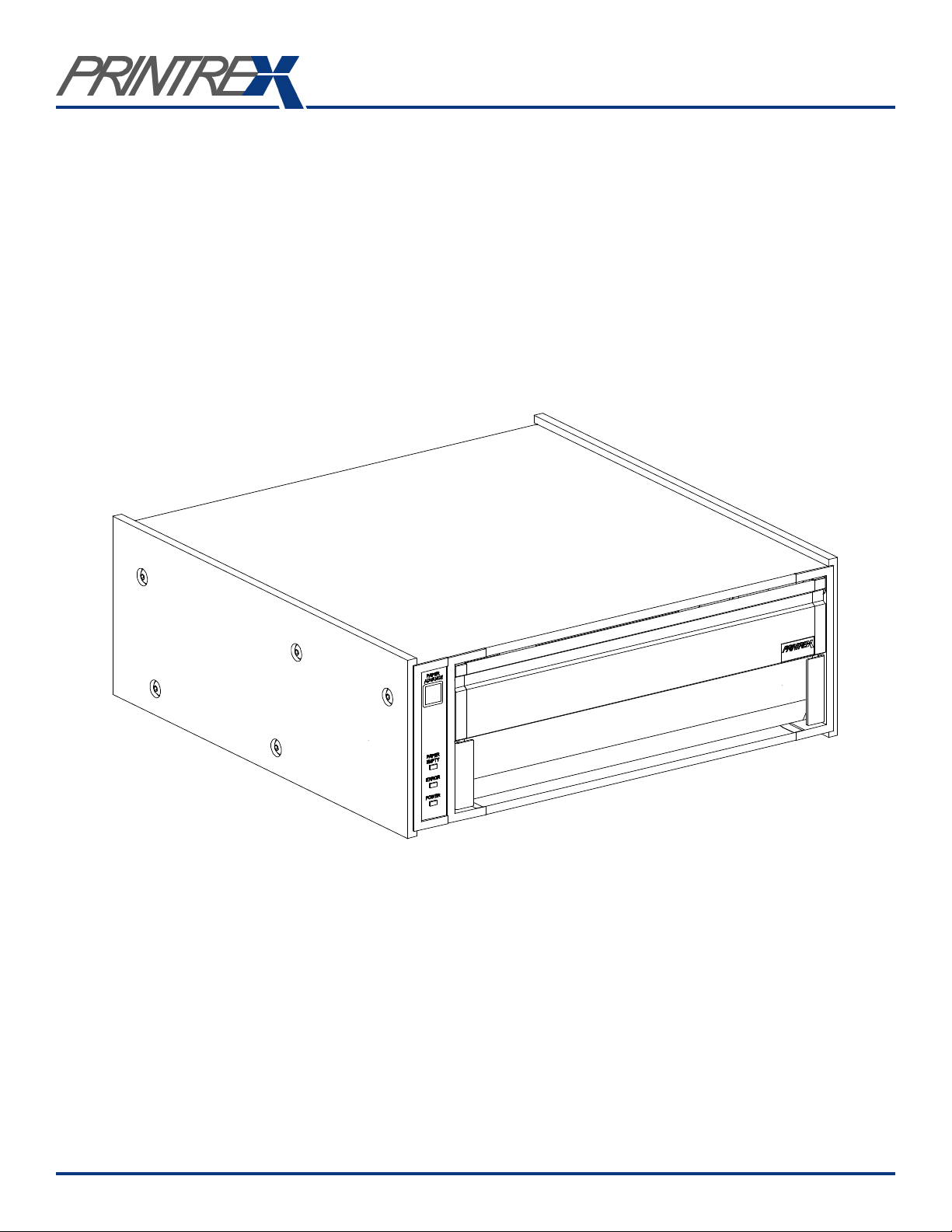
This User Guide describes the general operation and care of the DT (Desk Top) Chassis
series of industrial printers/plotters. The specific DT Chassis models covered by this guide
are the 840 DL/G, 820 DL/G, 820G and 810.
These products are designed for use in a variety of environments, including rugged mobile
data logging and exploration systems. While highly durable and reliable in service, best
performance and product life will be assured if some degree of care is taken when installing
the printers and when providing routine maintenance.
Reading the following sections describing the setup, operation and basic care of the printer
will very likely answer questions you might have regarding these aspects of using Printrex
products. Should you have further questions, more information is available as described in
the Additional Documentation section of this guide. If the documentation fails to address
your concerns, please contact Printrex support (see Contact Information) and we will make
every effort to provide a solution.
Refer to the following table for the discriminating DT Chassis features.
Model 840DL/G 820DL/G 820G 810
Print Speed (ips) 4 2 2 1
Integrated Internal Roll ü ü ü ü
Bottom Feed Fan-fold ü ü - -
Film/Mylar Media Support ü ü ü ü
Win95/98/ME and Win2000/XP Support ü ü ü ü
Vertical Line Adjustment ü ü ü ü
Extended Media Controls ü ü ü -
32 Level Gray Scale Printing ü ü ü -
Autorange 115/220VAC Power ü ü ü ü
Fan Cooled ü - - -
CE Certification (ITE, Safety and EMC) ü ü ü ü
FCC Class A ü ü ü ü
Firmware (Software)
Information
Copyright Information
The Firmware (Software) resident in the Printer is owned by Printrex or its suppliers and is
licensed for used only on a single printer in the user’s Trade or Business. The User agrees
not to, and not to authorize or permit any other person or party to duplicate or copy the
Firmware or the information contained in the nonvolatile or programmable memory. The
firmware (Software) is protected by applicable copyright laws and Printrex retains all rights
not expressly granted. In no event will Printrex or its suppliers be liable for any damages or
loss, including direct, incidental, economic, special, or consequential damages arising out
of the use or inability to use the Firmware (Software).
Windows and Windows NT are trademarks and Microsoft is a registered trademark of
Microsoft Corporation.
Ethernet is a registered trademark of Xerox Corporation.
All other brand and product names are trademarks, service marks, registered trademarks or
registered service marks of their respective companies.
DT Chassis Printers/Plotters
Page 4
Introduction
1-2
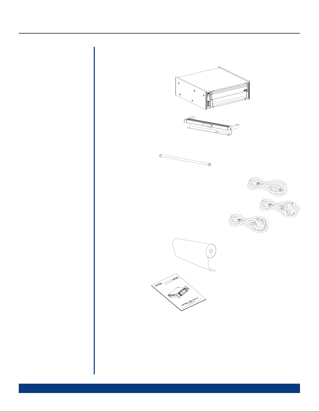
Package Contents
You should find the following items when unpacking your printer. If any of these items are
not found with the printer, please contact Printrex Customer Service.
• DT Chassis Printer
• 8 3/4 Inch Paper Carrier
• Paper Rod
US
(SUS suffix)
• Power Cord (one of the three US, UK or Central Europe
plug type, according to the order number suffix)
Central Europe
United Kingdom
(SUK suffix)
• Thermal Paper Roll
• This Manual
There is also a styrene spacer that keeps the print head pressure off the platen during shipment
and storage. This spacer is not required for operation and can be discarded.
(SCE suffix)
DT Chassis Printers/Plotters
Page 5
Introduction
1-3
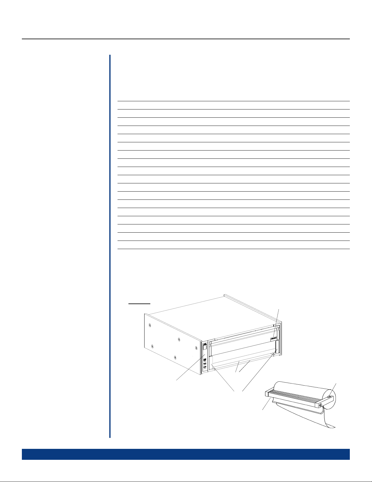
Getting Familiar
Feature Description Table
Refer to the Feature Description TableFigures 1 through 4 to familiarize yourself with the
features of the printer. The names of these features will be used throughout this guide.
FEATURE DESCRIPTION FIGURE
Bottom Feed Slot Paper entrance slot for bottom paper feed applications 3
Chassis Label Indicates Part Number, Revision, Full Model and Serial Number 2
Door Latches For opening and latching closed 1
Error Indicator Indicates error conditions (see Errors and Error Handling) 4
Form Sensor Window Form detector window to view form mark 5
Front Panel Operator controls and indicators 1
Model Label Indicates the installed print engine model 1
Paper Advance Button Advance paper and used to enter self-test 4
Paper Empty Indicator Indicates a paper empty condition 4
Paper Empty Switch Paper empty detection switch 5
Paper Rod Center spindle for internal roll paper supply 1
Paper Carrier Internal roll paper holder 1
Paper Tear Edge Paper tearing bar 1
Parallel Interface Connector High speed parallel interface connector to host computer 2
Platen Printer platen roller 5
Power Entry Module IEC power entry module for power entry 2
Power Indicator Indicates power is applied to the printer 4
Power Switch Controls power to the printer 2
Figure 1
DT Chassis Printers/Plotters
Front
Panel
Paper Tear
Edges
Door Latches
Paper Carrier
Model Label
Paper Rod
Page 6
Introduction
Getting Familiar
(Continued)
Figure 3
Figure 2
Parallel
Interface
Connector
1-4
Power
Switch
Power Entry
Module
Chassis
Label
Bottom Feed Slot
(840DL/G and
820DL/G only)
Figure 5
(Chassis not shown)
Platen
Paper
Empty
Switch
Form
Sensor
Window
Figure 4
Print Head
Assembly
Paper
Advance
Button
Paper
Empty
Indicator
Error
Indicator
Power
Indicator
PAPER
ADVANCE
PAPER
EMPTY
ERROR
POWER
DT Chassis Printers/Plotters
Page 7

System Setup
2-1
OEM
Configurations
Connecting the
Parallel Interface
Many different OEM organizations have been integrating Printrex products into combined
hardware and software systems; some for nearly 20 years. These complete-solution products
may be assembled in closed physical packaging or racks, or may consist of pre-configured
computer hardware that is deployed like any other office equipment. Software may be
command-line or graphically operated, and might be installed with a Unix-type or Microsoft
operating system. Interconnection interfaces include various types of parallel or serial
ports, USB and/or Ethernet.
While Printrex has experience in supporting the development of a variety of these OEM
systems, it is impossible for us to maintain the information and knowledge necessary to
provide detailed support in the operation of these systems. Persons having questions
regarding use of a specific product are best advised to consult the documentation or support
services provided by the OEM.
For clients directly receiving Printrex products to install as end users into existing or new
systems, we wish to make the installation process as trouble-free as possible. Several
documents are available for reference which are intended to describe the most common
installation scenarios (see the Additional Documentation section of this guide).
First, be sure to use a high-quality cable. The cable should be marked “IEEE-1284” to
indicate compliance with this communications standard. Inexpensive cables are electrically
inferior and can result in unnecessary communications errors.
Connecting the
Power Cord
Connect the 25-pin connector end of the cable to the parallel port of the computer. Use the
screw locks to secure the cable, but do not tighten excessively.
Make sure the printer power is off, then, plug the Centronics 36-pin connector end of the
cable into the printer and engage the spring clips to lock the connector.
Avoid making any other connections between computer and printer, whether to add extension
cables or to install daisy-chain disk drives or scanners. Integrity of communications is
greatly degraded when these items are in the signal path.
For other installation and connection options, please refer to the Printrex System
Administrator’s Guide.
First turn Power Switch to the off position (the off position is shown by the international
symbol “O”). Connect the IEC female end of the cord to the power connector on the rear of
the printer chassis. Plug the male connector into a properly grounded three- pin AC main
power outlet.
Do not use a “cheater” connector in order to use an inexpensive two-wire outlet or extension
cord. This defeats the grounding protection of the product and may introduce a serious
electrocution hazard in wet environments.
DT Chassis Printers/Plotters
Page 8

System Setup
2-2
Operating System
Setup
WindowsTM 2000/XP
The majority of Printrex customers use our printers with computing equipment that functions
with the support of an operating system. Microsoft Windows XP and Windows 2000 are
the most prevalent systems in current use. In order to provide the best quality of printed
output and most convenient user interface, Printrex continually reviews and updates drivers
for these platforms.
The ‘consumer’ operating systems ( Windows 95, 98, and ME ) are in the twilight of support
by Microsoft and are therefore supported at a lower priority by Printrex as well. Specific
issues regarding current drivers for these platforms may be referred to Printrex technical
support for correction; custom feature additions will be addressed on a per request basis.
The paragraphs below apply to users installing printers by connecting directly to the computer
in use. For connecting to a network, see the following section on Network Setup.
Because drivers for these platforms are subject to periodic updates, visit the Printrex website
( www.printrex.com/drivers.htm ) and download the most recent drivers. Expand the
compressed file onto a floppy disk and open the Printers folder ( Start – Settings – Printers).
Start the Add Printer wizard and follow the instructions, selecting Have Disk when prompted
for ‘Manufacturers’ and ‘Printers’.
After completing the wizard, right-click on the new printer icon in the Printers folder, and
select ‘Printing Preferences’. Click the Advanced... button to display the Advanced Options
dialog. This determines the “default” settings of the printer. Most users will wish to change
the Paper Size from ‘Letter’ to the actual form loaded in the printer, as well as the Media
Selection and Form Marker Type. Other settings may need adjustment as well, depending
on application.
For further information on installation, see publication 1028-0061, Printrex Driver Installation
Guide.
After installation, publication 1028-0062, Printrex Windows Driver User Guide
used as a reference in applying the driver settings needed for a particular printing task.
Many different types of applications can be accommodated by the drivers, using a variety
of media. While the default control values are a good starting point for most print jobs,
many users will wish to fine-tune driver settings to obtain the best quality possible.
WindowsTM 95/98/ME
First, check the Printrex website for updated driver versions ( www.printrex.com/drivers.htm).
After extracting the compressed driver files to a floppy disk, go to the Start – Settings –
Printers folder, and double-click Add Printer. Proceed with installation, and click the Have
Disk button when the ‘Manufacturer’ - ‘Model’ dialog is displayed. When the wizard
finishes, right-click on the printer icon and select ‘Properties’. Make adjustments as needed,
for paper size, media type, and other features. For further information on installation, see
publication 1028-0063, Printrex System Administrator’s Guide
DT Chassis Printers/Plotters
may be
.
Page 9

System Setup
2-3
UNIX and Other Operating
Systems
Network Setup
At this time, Printrex does not distribute filter files for UNIX (and UNIX-type) platforms.
Users of applications designed for use on these systems are advised to contact the application
vendor for assistance with setup.
Many permutations of network connections and configurations exist. It is well worth taking
some time to design the installation with consideration to future expansion and updates.
When connecting the printer within a mixed environment, there are additional choices
available and decisions to be made. Hardware print server boxes provide multi-protocol
support for numerous platform configurations and communications standards.
Refer to publication 1028-0063, Printrex System Administrators Guide
for further information.
DT Chassis Printers/Plotters
Page 10

Operation
3-1
Loading Paper
Loading An Internal Roll
Unlock the door of the printer by
pressing on the open circles printed on
the two latches at the lower corners of
the door. Pull up on the latches to open
the door.
2 Remove Paper Holder
1 Unlock Door
Remove the paper carrier from the
printer and remove the paper rod
from the carrier. Slip the empty
core off the paper rod.
Slip the paper rod through the core of
the new paper roll and install the paper
roll on the carrier so the paper feeds
from the top of the roll toward the front
of the carrier. Feed a few inches of
paper from the roll so it will extend
over the platen after insertion.
Insert the paper carrier in the printer and
close the door with the latches unlocked.
4 Lock Door
3 Insert Roll In Printer
Press on the solid circles printed on the
door latches to lock them. Tear off the
extra paper.
DT Chassis Printers/Plotters
Page 11

Operation
3-2
Loading Paper
Continued
Loading External Media
(Models 840DL/G and
820DL/G only)
Loading external media is similar to loading an internal roll. The difference being the paper
is threaded through the bottom feed slot. Note: The printer is shown with an optional Paper
Tray. See Accessories Section 5-2 for ordering information.
1 Place Printer On Stand
Place the printer on the paper tray.
The printer position is set by the feet
and side plates of the paper tray.
2 Rotate Printer to Upright Position
Rotate the printer to the
upright position, open
the door and remove
the paper carrier.
Paper Tray
3 Thread Paper
Printer
4 Return Printer to Operating Position
Return the printer to the
horizontal position, insert
paper carrier and close
the door.
Insert paper through the Bottom Feed
Slot and out through the door as
shown. Observe the orientation of the
Forms Mark for correct top-of-form
operation.
Position 11 inch forms even with the
ends of the paper guides for
correct position. Center API
forms between the ends of
the paper guides for
correct position.
Paper Guides
Note: The paper carrier must be
installed to position the paper over
the paper empty sensor and the
form mark sensor.
Forms Mark
DT Chassis Printers/Plotters
Page 12

Operation
3-3
Tearing Paper
Forms Marks
There are two tear bars; one on the bottom of the front door for tearing up and one on the
printer housing for tearing down. Pull up or down at approximately a 45° angle and slightly
to the right or left to tear the paper.
o
45
The forms mark sensor is located in the front right side of the printer. Be sure the paper is
loaded as shown below for correct top of form (TOF) detection. Also, be sure the paper size
TM
is correctly selected in the Windows
A listing of media providers that supply paper with the
specified form marker location can be found on the
driver.
Insert into printer
0.5 In.
Printrex web site (www.printrex.com). Most other media
suppliers can supply compatibly marked forms provided
they receive the marker specifications shown to
Perforation
0.25 In.
0.5 In.
the right.
Running Self Test
To perform self test, press and hold the PAPER ADVANCE button while turning on power.
The PAPER ADVANCE button may be released after self test has started. In self test, the
ERROR indicator lights and a printout of model, interface type, firmware version and other
various test patterns is started. The test printout will stop after the last test pattern is printed
and the printer will exit self test and return to normal operating mode.
There are times when it is useful to have the test pattern repeated. If the PAPER ADVANCE
button is held while the first self test pattern is finishing, the printer will enter a repeating
self test mode where the entire self test pattern is repeated until the unit is powered off.
DT Chassis Printers/Plotters
Perforation
Forms Mark
Uncoated side
of paper
Coated side
of paper
Forms mark
Page 13

Operation
3-4
Advancing Paper
Printing
After loading paper, or any time you wish to advance paper, press the Paper Advance button
on the front panel. The printer will feed paper as long as the button is pressed, but will stop
when either of two conditions is met:
• If the paper has form markers printed on the back surface, the printer will stop
when a marker is detected.
• The logical page length has passed without a form marker being seen. The powerup default page length is 16.7 inches. This length may be changed by sending the
printer control codes in software.
Releasing the button and pressing again repeats the cycle of feeding and stopping.
When print jobs are sent to the printer continuously, there is no mechanical duty cycle
limitation; some users report 10 hours a day of nonstop printing as normal usage. However,
if the print data contains an unusually high proportion of black areas, the printer may go
into an over-temperature condition. This may also occur when printing less dense print
jobs if the ambient temperature is very high. Refer to the following section on Errors and
Error Handling for information on the front-panel indication of temperature errors. Recovery
from temperature errors is automatic, and needs no user action to resume printing.
Clearing a
Paper Jam
Additional Controls
If paper has been loaded askew, or has been torn off forcefully, or is damp, the paper may
feed abnormally and wrap around the platen roller. These occurrences are extremely rare,
but it is important to know the following method of clearing the jam:
• Turn off power to the printer.
• Open the printer door, and remove the paper holder and roller.
• Tear off the incoming paper (either from the roll, or fanfold supply).
• Pull on the free end of paper with one hand, while turning the platen roller with
the other hand, to unroll paper from the platen.
• Do not use a razor, knife or sharp object of any kind to cut the paper off of the
platen roller. Nicking or cutting the roller surface will result in worsening damage
to the platen with continued use of the printer.
• Be very careful not to damage the print head that is exposed on the underside of
the door. This should not be an issue if only bare hands are used to free the paper.
The Front Panel controls are intentionally minimal. This ensures that one user’s print jobs in
a network environment are not ruined by other users manually making unannounced changes
to printer settings. The Printrex Windows drivers send control codes to the printer for each
print job, so it is important to check driver settings before printing. Note that some
geotechnical applications bypass the Windows drivers, and provide a limited subset of
printer controls. Check with your application’s documentation to determine if this is the
case. If so, settings made in the Windows driver will not affect printing from these
applications.
DT Chassis Printers/Plotters
Page 14

Operation
3-5
Errors and Error
Handling
The Error Indicator on the Front Panel indicates an error condition of the printer. This indication
is in the form of a two digit error code expressed as a series of long flashes (for the tens digit)
then short flashes (for the ones digit). The tens digit flash is twice as long as the ones digit
flash. Example: One long flash followed by two short flashes indicates an error code of 12
(Door Open).
The Error Indicator will continue to flash the error code while the error condition exists.
Refer to the following table for a list of error codes and their meaning.
ERROR
CODE NAME DESCRIPTION
11 Paper Empty A paper empty condition exists.
Cleared by loading paper.
12 Door Open One or both of the Door Latches are unlatched.
(1)
21
22 Over Voltage The internal DC supply voltage is too high to print properly.
23
24 Over Temperature The thermal head is overheated.
NOTE 1: Model 810 does not indicate an Under Voltage or an Under Temperature condition. The model 810
printer will print as best as possible given the voltage or temperature is lower than nominally expected.
Under Voltage The internal DC supply voltage is too low to print properly.
(1)
Under Temperature The thermal head is too cold to print properly.
Cleared by latching both door latches.
Service is generally required to clear this condition.
Service is generally required to clear this condition.
Cleared when the ambient temperature sufficiently increases.
Cleared when the thermal head cools off.
Troubleshooting
This section lists a few common questions that are received by Printrex support staff and the
answers most likely to fix the problem. For further information, see the Printrex System
Administrator’s Guide.
1. The printer seems to be working but nothing is printed.
The thermal paper has one side that has a thermal sensitive coating while the other side is
not coated. Be sure the thermally coated side is facing upward (as the paper is exiting the
printer).
2. My printer is too slow! What’s wrong?
(Windows XP/2000/NT4)
These operating systems do not support high speed data transfer using the default (Microsoft)
parallel port driver. Printrex recommends using a USB to Parallel converter cable when
connecting the printer directly to PCs using these operating systems.
(Windows 95/98/ME)
Check the parallel port settings in the BIOS and be sure it’s set to ECP mode.
3. I’m using fanfold paper with form markers, but the printer stops in the wrong place.
What driver settings should I use?
Be sure to set the Paper Size to the actual size of the paper (8.75 x 6.25), and enable End-ofJob Form Feed. Also, see that the Form Marker setting (in Windows XP/2000 driver) matches
the actual printed location of the marker. Check that the paper is loaded correctly: looking
at the front of the printer, the marker should be on the right side, on the bottom of the paper.
DT Chassis Printers/Plotters
Page 15

Operation
3-6
Troubleshooting
(Continued)
4. I’m trying to print TIFF files, but the printed output is clipped off. How do I print the
whole log?
This question has come from the geotechnical community frequently over the last several
years. Commonly, users view TIFF logs in Windows Imaging, the free viewer provided in
the Programs- Accessories folder. Unfortunately, this is a single-page application: it is
designed for simple photograph- size viewing and printing. Further, the Windows printing
subsystem (prior to Windows 2000) limited printer pages to 32,766 raster lines (approximately
163 inches long for the Printrex printers), so the longest log that could be printed from
Imaging was just 13 feet long. In Windows XP, the Imaging applet was replaced by a new
Paint applet that does print using multiple printer pages. In this case, set the printer page
size to the paper’s page size (8.75 x 6.25 half page), and Paint will generate as many printer
pages as needed to print the log.
In most of the larger geotechnical organizations, proprietary viewers have been written for
internal use by authorized staff and customers. Remarkably, there are very few options for
other users of TIFF log files who are not using Windows XP, or who find the XP Paint
application too primitive.
Printrex welcomes comments regarding requirements and features for log viewing tools,
for possible development of a viewer application for our customers.
5. Every time I start my program, I have to change printer settings. How do I change the
default driver settings?
In Windows 95/98/ME, go to the Start – Settings – Printers folder. Right-click on the printer
icon, and select ‘Properties’. In Windows NT4, right-click on the printer, and select
‘Document Defaults’... not ‘Properties’. In Windows XP/2000, right-click on the printer,
and select ‘Printing Preferences’. (If you select ‘Properties’, go to the ‘General’ tab, and
click the ‘Printing Preferences’ button.
In Windows NT4/2000/XP, changes to the printer settings done from within an application
are generally not saved unless some unusual program coding is done.
6. Self test prints out OK but when I print from the computer I get garbage.
Common problems for this symptom are the parallel cable or the printer driver that is being
used. Be sure the parallel cable is appropriately connected (see section Connecting the
Parallel Cable). Also, be sure the printer driver is for the specific model printer that is being
used.
7. Some times the fan-fold paper skews to one side or the other. How do I correct this?
The Printrex printers are designed to work with a wide
variety of media. A paper skewing problem is
normally corrected by realigning the paper. This
is done by opening the door, straightening the
paper and closing the door. We have found
however, that under some conditions (generally with
very thin paper) the problem may persist. If this is the case, we suggest threading the paper
over a full internal roll of paper (as shown) to remedy the situation.
DT Chassis Printers/Plotters
Page 16

Care and Cleaning
4-1
General Cleaning
Protecting the
Thermal Head
There is no regular cleaning required for proper operation of the printer, however the
printer surfaces are designed and manufactured to permit cleaning with the following
cleaning agents:
• Isopropyl alcohol
• Ammonia
• Chlorine bleach (1:10 concentration with water)
• Hexachlorophene (PhisoHex)
• Glutaraldehyde (Cidex)
It is recommended that a soft cloth dampened with the cleaning agent be used to clean
the surfaces of the printer. Do NOT submerse or allow spills onto or in the product.
The thermal head incorporates a protective glaze coating and is generally resistant to
harsh environments, however the following precautions should be taken regarding the
thermal head surface:
• Do not allow the thermal head to come in contact with sharp or hard objects.
• Do not allow thermal paper debris to accumulate on the thermal head.
• Do not allow condensation to accumulate on the thermal head.
• Use only Printrex approved thermal paper
• Do not expose the thermal head to abrasive cleansers.
Cleaning The
Thermal Head
Cleaning The
Form Sensor
Long Term
Storage
Paper dust or other foreign material may occasionally accumulate on the thermal print
head. This will be indicated by light print or no print in a narrow band down the length of
the paper. In order to eliminate the thermal paper debris buildup, it is recommended to
use a soft cloth moistened with one of the following cleaning agents:
• Isopropyl alcohol
• Ethanol
A light wiping along the length of the print head is adequate. Allow the print head to dry
before resuming printing. It can be wiped dry with a soft, clean cloth. Do NOT submerse
or allow spills onto the thermal head.
Paper dust or other foreign material may occasionally accumulate on the form sensor. This
will be indicated by missing the top of form position (some time after it has been correctly
stopping at the top of form). The form sensor can be cleaned with an aerosol air spray or
soft bristled brush. It is located just under the form sensor window.
With the paper door closed, the thermal head applies a considerable pressure on the
platen (approximately 8 kg). If the printer is stored for long periods of time with the paper
door closed (especially in cold temperatures), it is possible that a slight flat area is induced
in the platen. It is recommended the paper door be kept in an unlatched condition for
extended periods of storage. Note: The condition of a flat spot on the platen is not permanent
and the platen will return to it’s normal roundness after 10 or so minutes of resumed
operation.
DT Chassis Printers/Plotters
Page 17

Support / Service
5-1
Warranty
Printrex products are warranted to be free from failures due to defects in material and
workmanship for twelve (12) months from the date of purchase. During this 12 month
period Printrex will, at its sole discretion, replace or repair at no charge the product which,
in its opinion, is defective.
If the failed product has been modified without Printrex’s consent or if the failure is the
result of misuse, abuse or misapplication, Printrex has no obligation to repair or replace the
failed product.
Consumables Warranty: Printrex warrants that the thermal print head will be free from
defects for the Expected Life of the printhead but not more than one (1) year from the date
of purchase. The Expected Life of the printhead is considered to be the lesser of, A) fifty (50)
kilometers of delivered media or B) one hundred million (10
element (approximately 12.7 km of converted printout for any given print element).
Except as expressly provided above, the hardware and accompanying written materials
(including the User’s Guide) are provided ‘as is’ without warranty of any kind, including the
implied warranties of merchantability and fitness for a particular purpose, even if Printrex
has been advised of that purpose. In no event will Printrex be liable for any direct, indirect,
consequential, or incidental damages arising out of the use of or inability to use such product
even if Printrex has been advised of the possibility of such damages. Some states do not
allow the exclusion or limitation of liability for consequential or incidental damages, so the
above limitation may not apply.
8
) pulses of an individual print
Service Policy
Obtaining Service
Self Service
Following the warranty period Printrex will repair defective products and will charge a fee
to cover handling and service costs based on Printrex’s then-current price schedule.
Before returning a failed unit, the buyer must first obtain a Return Material Authorization
(RMA) number by contacting Printrex’s Customer Service. The RMA number should be
prominently displayed on the outside of the returned package and on the accompanying
packing list. Printrex cannot be held responsible for any package returned without an RMA
number. The model and serial number of the printer is on the chassis label located on the
rear of the printer. Please have this information available when service is required.
The user is responsible for packing the failed product in original or equivalent packaging
for shipment, and for the charges to ship the failed product to Printrex. Printrex is responsible
for charges to ship the repaired or replaced product if under warranty. If any charge to you
is involved, Printrex, at its sole option, will bill you or return the product C.O.D.
Printrex recognizes that some customers have service departments that are capable of
servicing the Printrex products. For this case, Printrex offers a Self Service Reference. This
reference includes assembly drawings with bills of material so that replaceable internal
components can be identified and ordered. Please contact Printrex Customer Service to
obtain a Self Service Reference for your product(s). For self service, the owner assumes the
risk of damage to the unit and may violate the warranty.
DT Chassis Printers/Plotters
Page 18

Support / Service
5-2
Service Centers
Spare Parts
Supplies
Accessories
A list of service centers are available from the Printrex web site. Please refer to:
www.printrex.com
Description .................................................................................................. Part Number
Paper Carrier ................................................................................................... 2111-0189
Paper Rod........................................................................................................ 2012-0008
Power Cord (Central Europe plug) ................................................................... 2237-0004
Power Cord (United Kingdom plug)................................................................. 2237-0061
Power Cord (United States plug) ...................................................................... 2237-0007
Print Head Assembly ....................................................................................... 2111-0175
Description .................................................................................................. Part Number
Roll Paper, 150’ length .................................................................................... 2316-0001
Roll-FF Paper, 150’ roll (6 1/4” Perf. Intervals) ................................................. 2316-0013
Fan-Fold Paper, 8.75 x 6.25 inch, 800 sheet box ............................................. 2316-0011
Roll Matte Film, 117’ length ............................................................................ 2316-0009
Description .................................................................................................. Part Number
USB Adapter Kit .............................................................................................. 2012-0030
Paper Tray (Bottom feed tray, for 840DL/G and 820DL/G) ............................... 2320-0014
Additional
Documentation
WindowsTM Drivers
Contact
Information
Description .................................................................................................. Part Number
Driver Installation Guide, Win2000/XP ........................................................... 1028-0061
Driver User Guide, Win2000/XP ..................................................................... 1028-0062
Self Service Guide, 840DL/G DT Chassis ........................................................ 1028-0073
Self Service Guide, 820DL/G DT Chassis ........................................................ 1028-0075
Self Service Guide, 820G DT Chassis.............................................................. 1028-0077
Self Service Guide, 810 DT Chassis ................................................................ 1028-0079
System Administrators’ Guide ......................................................................... 1028-0063
Windows drivers are available from the Printrex Web Site. Please refer to:
www.printrex.com/drivers.htm
Printrex, Inc.
276 East Gish Road
San Jose, CA 95112-4703 USA
Telephone: +408.573.1200
Fax: +408.573.1600
E-mail: info@printrex.com
DT Chassis Printers/Plotters
Page 19

Safety
6-1
Restriction on Use
Grounding
Power Cord
Serviceability
Use this equipment only for its intended use as described in this guide.
• Do not use power supplied outside the specified voltage/hertz range.
• Do not block any openings on the equipment.
• Do not use corrosive chemicals or vapors on the equipment.
• Do not expose equipment to rain or spills or moisture.
This equipment must be grounded to conform with the normative safety standards. Connect
only to a properly grounded outlet.
The power cord supplied with the equipment is rated and approved for service to this
equipment.
• Do not operate the equipment if it has a damaged power cord or plug.
• Do not immerse the power cord or plug in water.
• Do not use a power cord other than that supplied with the equipment.
There are no user-serviceable parts inside the equipment. Refer all service to a qualified
service technician.
Regulatory
Compliance
FCC Compliance
This unit has been tested and found to comply with the limits for a Class A digital device,
pursuant to Part 15 of the FCC Rules. These limits are designed to provide reasonable protection
against harmful interference when the equipment is operated in a commercial environment.
This equipment generates, uses, and can radiate radio frequency energy and, if not installed
and used in accordance with the instruction manual, may cause harmful interference to
radio communications. Operation of this equipment in a residential area is likely to cause
harmful interference in which case the user will be required to correct the interference at his
own expense.
CE Compliance
The manufacturer declares that this product conforms to the following standards or other
normative documents:
EMC: EN 55022:1994 Limits and Methods of Measurements of Radio Interference
Characteristics of Information Technology Equipment, Class A, including
amendments A1:1995, A2:1997
EN 50024:1998 Limits and method of measurement of Immunity
characteristics of Information technology equipment
Safety: EN 60950:1992 Safety of information technology equipment including
electrical business equipment, including amendments A1:1993, A2:1993,
A3:1995, A4:1997, A11:1997
DT Chassis Printers/Plotters
Page 20

Technical Specifications
7-1
General
Specifications
Performance
Forms
Compatibility
Power Requirements (840DL/G) ............................... 100-240 VAC, 500 VA, 50~60Hz
Power Requirements (820DL/G and 820G) .............. 100-240 VAC, 240 VA, 50~60Hz
Power Requirements (810) ........................................ 100-240 VAC, 150 VA, 50~60Hz
Height ................................................................................................4.5 inch (114 mm)
Width .............................................................................................. 12.2 inch (310 mm)
Depth .............................................................................................. 12.4 inch (315 mm)
Unit Weight.............................................................................................. 14 lbs (6.4 kg)
Shipping Weight ...................................................................................... 18 lbs (8.2 kg)
Interface ...........................................................................................High Speed Parallel
Print Speed (840DL/G) ........................................................................ 0.5 to 4 inch/sec
Print Speed (820DL/G and 820G) ....................................................... 0.5 to 2 inch/sec
Print Speed (810) ................................................................................. 0.5 to 1 inch/sec
Horizontal Resolution .................................................................... 203 dpi (8 dots/mm)
Vertical Resolution ......................................................................... 203 dpi (8 dots/mm)
Overall Forms Width ...................................................................... 8.75 inch (222 mm)
Internal Roll Capacity................................................... 2.6 inch (66 mm) diameter roll
For 840DL/G and 820DL/G:
Bottom Feed Roll Capacity.....................................5 inch (152 mm) diameter roll
Bottom Feed Fan-fold Capacity ............................. 18 inch (457 mm) stack height
Forms Mark ............................................See Section 3-3 for forms mark specifications
Environmental
Regulatory
Information in this document is subject to change without notice and does not represent a commitment on the part of
Printrex, Inc. No part of this manual may be reproduced or transmitted in any form or by any means, for any purpose other
Printrex
• 276 East Gish Road • San Jose, CA 95112-4703 • Ph: (408) 573-1200 • Fax: (408) 573-1600 • www.printrex.com
Storage Temperature ....................................................... -40oC (-40oF) to 60oC (140oF)
Operating Temperature (non-condensing) ......................... 5
Shock & Vibration (non-operational) ........................................ 3G, 0 to 50 Hz, 3 axes
Environmental Ingress (IEC 529) ............................................................................. IP54
CE ...............................................................................................ITE Directive, Edition 2
FCC ...................................................................................................................... Class A
than the purchaser’s personal use, without the expressed written permission of Printrex, Inc.
All rights reserved. Printed in the United States of America.
© Copyright 2003 by Printrex, Inc.
Part Number: 1028-0071 Rev 1
o
C (41oF) to 40oC (104oF)
 Loading...