


4411-0101 Version 2.F April 14, 2010
*4411-0101*
Copyright 2003-2010 Princeton Instruments, a division of Roper Scientific, Inc. 3660 Quakerbridge Rd
Trenton, NJ 08619
TEL: 800-874-9789 / 609-587-9797 FAX: 609-587-1970
All rights reserved. No part of this publication may be reproduced by any means without the written permission of Princeton Instruments, a division Roper Scientific, Inc. ("Princeton Instruments").
Printed in the United States of America.
eXcelon is a trademark of Princeton Instruments. IPLab is a trademark of Scanalytics, Inc.
LabVIEW is a registered trademark of National Instruments, Inc. Logitech is a registered trademark of Logitech International S.A.
Mac and Macintosh are registered trademarks of Apple Computer, Inc. PVCAM is a registered trademark of Roper Scientific, Inc.
Radio Shack is a registered trademark of TRS Quality, Inc.
Scientific Imaging ToolKit and SITK are trademarks of R Cubed Software Consultants, LLC. SpectraPro is a trademark of Acton Research Corporation.
Styrofoam is a registered trademark of Dow Chemical Company. TAXI is a registered trademark of AMD Corporation.
Windows, Windows NT, and Windows Vista are registered trademarks of Microsoft Corporation in the United States and/or other countries.
The information in this publication is believed to be accurate as of the publication release date. However, Princeton Instruments does not assume any responsibility for any consequences including any damages resulting from the use thereof. The information contained herein is subject to change without notice. Revision of this publication may be issued to incorporate such change.

Table of Contents
Chapter 1 Introduction ....................................................................................... |
11 |
Description........................................................................................................................ |
11 |
System Components ......................................................................................................... |
11 |
Standard Components ................................................................................................ |
11 |
Optional System Components .................................................................................... |
11 |
Application Software ........................................................................................................ |
12 |
About this Manual ............................................................................................................ |
12 |
Manual Organization.................................................................................................. |
12 |
Safety Related Symbols Used in this Manual ............................................................ |
13 |
Grounding and Safety ....................................................................................................... |
13 |
ESD Precautions ............................................................................................................... |
13 |
Additional Precautions ..................................................................................................... |
14 |
Detector and Controller.............................................................................................. |
14 |
Shutter ........................................................................................................................ |
14 |
Spectrometer Support ....................................................................................................... |
14 |
Enhancement Coatings ..................................................................................................... |
15 |
Cleaning ............................................................................................................................ |
15 |
Detector and Controller.............................................................................................. |
15 |
Optical Surfaces ......................................................................................................... |
15 |
Repairs .............................................................................................................................. |
15 |
Chapter 2 System Component Descriptions ................................................... |
17 |
Spec-10 Detector .............................................................................................................. |
17 |
ST-133 Controller ............................................................................................................. |
18 |
Cables ............................................................................................................................... |
21 |
Interface Card ................................................................................................................... |
21 |
Application Software ........................................................................................................ |
21 |
User Manuals .................................................................................................................... |
22 |
Chapter 3 Installation Overview ........................................................................ |
23 |
Chapter 4 System Setup .................................................................................... |
25 |
Unpacking the System ...................................................................................................... |
25 |
Checking the Equipment and Parts Inventory .................................................................. |
25 |
System Requirements ....................................................................................................... |
25 |
Environmental ............................................................................................................ |
25 |
Ventilation.................................................................................................................. |
26 |
Coolant ....................................................................................................................... |
26 |
Power.......................................................................................................................... |
26 |
Host Computer ........................................................................................................... |
27 |
Verifying Controller Voltage Setting ............................................................................... |
28 |
Installing the Application Software .................................................................................. |
28 |
Setting up the Communication Interface .......................................................................... |
29 |
Setting up a PCI Interface .......................................................................................... |
29 |
|
iii |

iv |
Spec-10 System Manual |
Version 2.F |
|
Setting up a USB 2.0 Interface................................................................................... |
30 |
|
Mounting to a Spectrometer ............................................................................................. |
33 |
|
Focal Plane Distance .................................................................................................. |
33 |
|
Optical Center of the Array........................................................................................ |
34 |
|
Array Orientation ....................................................................................................... |
34 |
|
Detector-Spectrometer Adapters ................................................................................ |
35 |
|
Setting up a Shutter........................................................................................................... |
35 |
|
Introduction ................................................................................................................ |
35 |
|
Internal Shutter........................................................................................................... |
35 |
|
External Shutter.......................................................................................................... |
36 |
|
Shutter Setting............................................................................................................ |
36 |
|
Connecting the Detector-Controller Cable ....................................................................... |
37 |
|
Connecting the Interface (Controller-Computer) Cable ................................................... |
37 |
|
TAXI® Cable .............................................................................................................. |
37 |
|
USB 2.0 Cable............................................................................................................ |
37 |
|
Entering the Default Camera System Parameters into WinSpec...................................... |
38 |
|
Making the Coolant Circulator-Detector Connections ..................................................... |
40 |
|
Filling the Dewar (LN-cooled Detectors)......................................................................... |
41 |
|
Procedure.................................................................................................................... |
42 |
|
Holding Times............................................................................................................ |
43 |
Chapter 5 Operation ........................................................................................... |
45 |
|
|
Introduction....................................................................................................................... |
45 |
|
USB 2.0 and System On/Off Sequences........................................................................... |
46 |
|
First Light ......................................................................................................................... |
46 |
|
Assumptions ............................................................................................................... |
47 |
|
Getting Started ........................................................................................................... |
47 |
|
Setting the Parameters................................................................................................ |
48 |
|
Focusing ..................................................................................................................... |
49 |
|
Data Collection........................................................................................................... |
50 |
|
Shutdown.................................................................................................................... |
50 |
|
Exposure and Signal ......................................................................................................... |
51 |
|
Introduction ................................................................................................................ |
51 |
|
CCD Array Architecture ............................................................................................ |
51 |
|
Exposure Time ........................................................................................................... |
51 |
|
Continuous Exposure ................................................................................................. |
52 |
|
Exposure with Shutter ................................................................................................ |
52 |
|
Cooling the CCD........................................................................................................ |
52 |
|
CCD Temperature Control ......................................................................................... |
54 |
|
Dark Charge ............................................................................................................... |
54 |
|
Saturation ................................................................................................................... |
55 |
|
Readout ............................................................................................................................. |
55 |
|
Introduction ................................................................................................................ |
55 |
|
Full Frame Readout.................................................................................................... |
56 |
|
Binning ....................................................................................................................... |
57 |
|
Output Amplifier Selection ........................................................................................ |
59 |
|
Analog Gain Control .................................................................................................. |
59 |
|
Digitization ....................................................................................................................... |
60 |
|
Introduction ................................................................................................................ |
60 |

Table of Contents |
v |
Digitization Rate ........................................................................................................ |
61 |
ADC Offset (Bias)...................................................................................................... |
61 |
Dark Current ..................................................................................................................... |
62 |
High Humidity .................................................................................................................. |
62 |
Shutter............................................................................................................................... |
62 |
TE-Cooled Detectors.................................................................................................. |
62 |
LN-Cooled Detectors ................................................................................................. |
62 |
Summary ........................................................................................................................... |
62 |
Chapter 6 Advanced Topics .............................................................................. |
63 |
Introduction....................................................................................................................... |
63 |
Standard Timing Modes ................................................................................................... |
63 |
Free Run ..................................................................................................................... |
65 |
External Sync ............................................................................................................. |
65 |
External Sync with Continuous Cleans...................................................................... |
67 |
Fast and Safe Speed Modes .............................................................................................. |
68 |
Kinetics Mode................................................................................................................... |
69 |
Introduction ................................................................................................................ |
69 |
Timing Modes ............................................................................................................ |
70 |
TTL Control...................................................................................................................... |
72 |
Introduction ................................................................................................................ |
72 |
TTL In ........................................................................................................................ |
72 |
Buffered vs. Latched Inputs ....................................................................................... |
73 |
TTL Out ..................................................................................................................... |
74 |
TTL Diagnostics Screen............................................................................................. |
74 |
Hardware Interface..................................................................................................... |
74 |
Chapter 7 Troubleshooting................................................................................ |
77 |
Introduction....................................................................................................................... |
77 |
Baseline Signal Suddenly Changes .................................................................................. |
78 |
Camera Stops Working..................................................................................................... |
78 |
Camera1 (or similar name) on Hardware Setup dialog box ............................................. |
78 |
Changing the ST-133 Line Voltage and Fuses ................................................................. |
79 |
Controller Is Not Responding ........................................................................................... |
80 |
Cooling Troubleshooting .................................................................................................. |
80 |
Temperature Lock cannot be Achieved or Maintained.............................................. |
80 |
Detector loses Temperature Lock .............................................................................. |
81 |
Gradual Deterioration of Cooling Capability............................................................. |
81 |
Data Loss or Serial Violation ........................................................................................... |
81 |
Data Overrun Due to Hardware Conflict message ........................................................... |
82 |
Data Overrun Has Occurred message ............................................................................... |
82 |
Demo is only Choice on Hardware Wizard:Interface dialog (Versions 2.5.19.0 |
|
and Earlier)................................................................................................................. |
83 |
Demo, High Speed PCI, and PCI(Timer) are Choices on Hardware |
|
Wizard:Interface dialog (Versions 2.5.19.0 and Earlier) ........................................... |
84 |
Detector Temperature, Acquire, and Focus are Grayed Out (Versions 2.5.19.0 |
|
and Earlier)................................................................................................................. |
86 |
Error Creating Controller message ................................................................................... |
87 |
Error Occurs at Computer Powerup ................................................................................. |
87 |

vi |
Spec-10 System Manual |
Version 2.F |
|
No CCD Named in the Hardware Wizard:CCD dialog (Versions 2.5.19.0 and |
|
|
Earlier)........................................................................................................................ |
88 |
|
Program Error message..................................................................................................... |
89 |
|
Removing/Installing a Plug-In Module............................................................................. |
89 |
|
Securing the Detector-Controller Cable Slide Latch ........................................................ |
91 |
|
Serial violations have occurred. Check interface cable. ................................................... |
92 |
|
Shutter Malfunctions ........................................................................................................ |
93 |
|
Vignetting ......................................................................................................................... |
93 |
Appendix A Specifications ................................................................................ |
95 |
|
|
Computer .......................................................................................................................... |
95 |
|
Controller.......................................................................................................................... |
95 |
|
Detector............................................................................................................................. |
97 |
Appendix B Outline Drawings ........................................................................... |
99 |
|
|
Liquid Nitrogen-Cooled Detector..................................................................................... |
99 |
|
Thermoelectrically-Cooled Detector .............................................................................. |
105 |
|
ST-133B Controller ........................................................................................................ |
107 |
|
ST-133A Controller ........................................................................................................ |
107 |
Appendix C Spectrometer Adapters............................................................... |
109 |
|
|
Acton (LN with shutter) ................................................................................................. |
110 |
|
Acton (LN without shutter) ............................................................................................ |
111 |
|
Acton (NTE/NTE 2/XP/XTE) ........................................................................................ |
112 |
|
Chromex 250 IS (LN with shutter) ................................................................................. |
113 |
|
Chromex 250 IS (LN without shutter)............................................................................ |
114 |
|
Chromex 250 IS (NTE/NTE 2/XP/XTE) ....................................................................... |
115 |
|
ISA HR 320 (LN with shutter) ....................................................................................... |
116 |
|
ISA HR 320 (LN without shutter) .................................................................................. |
117 |
|
ISA HR 320 (NTE/NTE 2/XP/XTE) .............................................................................. |
118 |
|
ISA HR 640 (LN without shutter) .................................................................................. |
119 |
|
ISA HR 640 (NTE/NTE 2/XP/XTE) .............................................................................. |
120 |
|
JY TRIAX family (LN without shutter) ......................................................................... |
121 |
|
JY TRIAX family (NTE/NTE 2/XP/XTE)..................................................................... |
122 |
|
SPEX 270M (LN with shutter) ....................................................................................... |
123 |
|
SPEX 270M (LN without shutter).................................................................................. |
124 |
|
SPEX 270M (NTE/NTE 2/XP/XTE) ............................................................................. |
125 |
|
SPEX 500M (LN with shutter) ....................................................................................... |
126 |
|
SPEX 500M (LN without shutter).................................................................................. |
127 |
|
SPEX 500M (NTE/NTE 2/XP/XTE) ............................................................................. |
128 |
|
SPEX TripleMate (LN with shutter) .............................................................................. |
129 |
|
SPEX TripleMate (LN without shutter) ......................................................................... |
130 |
|
SPEX TripleMate (NTE/NTE 2/XP/XTE) ..................................................................... |
131 |
Appendix D USB 2.0 Limitations..................................................................... |
133 |
|
Declarations of Conformity ............................................................................. |
135 |
|
|
LN Systems..................................................................................................................... |
136 |
|
NTE Systems .................................................................................................................. |
137 |
|
NTE2 Systems ................................................................................................................ |
138 |
|
TEA Systems .................................................................................................................. |
139 |

Table of Contents |
vii |
XTE Systems .................................................................................................................. |
140 |
XP Systems - 2 MHz....................................................................................................... |
141 |
XP Systems - 1 MHz with USB 2.0................................................................................ |
142 |
Warranty & Service........................................................................................... |
143 |
Limited Warranty............................................................................................................ |
143 |
Basic Limited One (1) Year Warranty ..................................................................... |
143 |
Limited One (1) Year Warranty on Refurbished or Discontinued Products............ |
143 |
XP Vacuum Chamber Limited Lifetime Warranty .................................................. |
143 |
Sealed Chamber Integrity Limited 12 Month Warranty .......................................... |
144 |
Vacuum Integrity Limited 12 Month Warranty ....................................................... |
144 |
Image Intensifier Detector Limited One Year Warranty ......................................... |
144 |
X-Ray Detector Limited One Year Warranty .......................................................... |
144 |
Software Limited Warranty...................................................................................... |
144 |
Owner's Manual and Troubleshooting ..................................................................... |
145 |
Your Responsibility ................................................................................................. |
145 |
Contact Information........................................................................................................ |
146 |
Index .................................................................................................................. |
147 |
Figures
Figure 1. Standard Components ...................................................................................... |
11 |
|
Figure 2. Power Switch Location (ST-133A and ST-133B) ........................................... |
19 |
|
Figure 3. |
ST-133 Rear Panel Callouts ............................................................................. |
20 |
Figure 4. System Diagram: TE-cooled Detector ............................................................. |
24 |
|
Figure 5. System Diagram: LN-cooled Detector ............................................................. |
24 |
|
Figure 6. Controller Power Module................................................................................. |
28 |
|
Figure 7. |
WinSpec Installation: Interface Card Driver Selection.................................... |
28 |
Figure 8. |
Shutter Setting for LN Detector 40 mm Internal Shutter ............................... |
35 |
Figure 9. |
Entrance Slit Shutter Mount............................................................................. |
36 |
Figure 10. Camera Detection Wizard - Welcome dialog box.......................................... |
38 |
|
Figure 11. RSConfig dialog box ...................................................................................... |
39 |
|
Figure 12. Hardware Setup wizard: PVCAM dialog box................................................ |
39 |
|
Figure 13. |
Coolant Ports .................................................................................................. |
41 |
Figure 14. Dewar Ports and Valves ................................................................................. |
42 |
|
Figure 15. Block Diagram of Light Path in System......................................................... |
45 |
|
Figure 16. Exposure of the CCD with Shutter Compensation......................................... |
51 |
|
Figure 17. WinSpec/32 Detector Temperature dialog box.............................................. |
54 |
|
Figure 18. Array Terms for a CCD with Dual Output Amplifiers ................................. |
55 |
|
Figure 19. |
Full Frame at Full Resolution ........................................................................ |
56 |
Figure 20. 2 × 2 Binning for Images................................................................................ |
58 |
|
Figure 21. |
Output Amplifier Selection ........................................................................... |
59 |
Figure 22. Analog Gain Switch on TEand LN-cooled Detectors................................. |
60 |
|
Figure 23. Chart of Safe and Fast Mode Operation......................................................... |
64 |
|
Figure 24. |
Free Run Timing Chart, part of the chart in Figure 23 ................................. |
65 |
Figure 25. Free Run Timing Diagram ............................................................................. |
65 |
|

viii |
Spec-10 System Manual |
Version 2.F |
Figure 26. Flowchart of Two External Sync Timing Options ......................................... |
66 |
|
Figure 27. Timing Diagram for External Sync Mode...................................................... |
67 |
|
Figure 28. |
Continuous Cleans Flowchart ........................................................................ |
67 |
Figure 29. Continuous Cleans Timing Diagram.............................................................. |
68 |
|
Figure 30. |
Kinetics Readout ............................................................................................ |
69 |
Figure 31. Hardware Setup dialog box ............................................................................ |
70 |
|
Figure 32. |
Experiment Setup dialog box ......................................................................... |
70 |
Figure 33. Free Run Timing Diagram ............................................................................. |
71 |
|
Figure 34. Single Trigger Timing Diagram ..................................................................... |
71 |
|
Figure 35. Multiple Trigger Timing Diagram ................................................................. |
72 |
|
Figure 36. TTL IN/OUT connector ................................................................................. |
74 |
|
Figure 37. |
TTL Diagnostics dialog box........................................................................... |
74 |
Figure 38. Camera1 in Controller Type (Camera Name) Field....................................... |
78 |
|
Figure 39. Power Input Module....................................................................................... |
79 |
|
Figure 40. |
Fuse Holder .................................................................................................... |
79 |
Figure 41. Data Overrun Due to Hardware Conflict dialog box ..................................... |
82 |
|
Figure 42. |
Hardware Wizard: Interface dialog box ......................................................... |
83 |
Figure 43. RSConfig dialog box ...................................................................................... |
83 |
|
Figure 44. Hardware Wizard: PVCAM dialog box ......................................................... |
84 |
|
Figure 45. |
Hardware Wizard: Interface dialog box ......................................................... |
84 |
Figure 46. RSConfig dialog box: Two Camera Styles .................................................... |
85 |
|
Figure 47. Hardware Wizard: PVCAM dialog box ........................................................ |
85 |
|
Figure 48. RSConfig dialog box: Two Camera Styles .................................................... |
86 |
|
Figure 49. |
Error Creating Controller dialog box ............................................................. |
87 |
Figure 50. Hardware Wizard: Detector/Camera/CCD dialog box................................... |
88 |
|
Figure 51. |
Program Error dialog box............................................................................... |
89 |
Figure 52. |
Module Installation ........................................................................................ |
90 |
Figure 53. |
Serial Violations Have Occurred dialog box ................................................. |
92 |
Figure 54. Side-On Dewar, Non-Shuttered: New Design................................................ |
99 |
|
Figure 55. Side-On Dewar, Shuttered: New Design...................................................... |
100 |
|
Figure 56. Side-On Dewar: Old Design......................................................................... |
101 |
|
Figure 57. End-On Dewar, Non-Shuttered: New Design .............................................. |
102 |
|
Figure 58. End-On Dewar, Shuttered: New Design ...................................................... |
103 |
|
Figure 59. End-On Dewar: Old Design ......................................................................... |
104 |
|
Figure 60. Spectrometer Mount (NTE/XP): Side View ................................................ |
105 |
|
Figure 61. Spectrometer Mount (NTE/XP): Front and Back Views ............................. |
105 |
|
Figure 62. Spectrometer Mount (NTE 2/XTE): Side View .......................................... |
106 |
|
Figure 63. Spectrometer Mount (NTE 2/XTE): Front and Back Views ....................... |
106 |
|
Figure 64. ST-133B Controller Dimensions.................................................................. |
107 |
|
Figure 65. ST-133A Controller Dimensions ................................................................. |
107 |
|

Table of Contents |
|
ix |
Tables |
|
|
Table 1. |
PCI Driver Files and Locations ......................................................................... |
30 |
Table 2. USB Driver Files and Locations........................................................................ |
32 |
|
Table 3. |
Focal Plane Distances........................................................................................ |
33 |
Table 4. |
ST-133 Shutter Drive Selection......................................................................... |
36 |
Table 5. CCD Array vs. Dewar Hold Time ..................................................................... |
43 |
|
Table 6. Approximate Temperature Range vs. Detector ................................................. |
53 |
|
Table 7. Approximate Readout Time for Some Spec-10 Arrays..................................... |
57 |
|
Table 8. Detector Timing Modes..................................................................................... |
63 |
|
Table 9. Bit Values with Decimal Equivalents: 1 = High, 0 = Low............................... |
73 |
|
Table 10. TTL In/Out connector pinout .......................................................................... |
74 |
|
Table 11. Features Supported under USB 2.0 ............................................................... |
133 |
|
x |
Spec-10 System Manual |
Version 2.F |
|
|
|
This page intentionally left blank.
Chapter 1
Introduction
Description
The Spec-10 family of detectors incorporates performance-optimized spectrometric CCDs, ultra-low-noise electronics, and full software control of both detector and spectrometer to produce a detection system that delivers the data you need. A Spec-10 system can be configured with a number of frontand back-illuminated scientific-grade CCDs (including eXcelonTM enabled back-illuminated CCDs) that are available only from Princeton Instruments. These exclusive detectors, developed jointly with CCD manufacturers, employ several design features engineered specifically towards optimizing performance parameters for spectroscopic experiments. The most obvious special characteristic, the rectangular array format of the CCDs, serves the dual purpose of providing fast spectral rates (small heights) and full spectral coverage (large widths).
eXcelon is a new CCD/EMCCD sensor technology jointly developed by Princeton Instruments, e2v, and Photometrics. CCDs using this technology provide three significant benefits:
Improved sensitivity – improved QE over broader wavelength region compared to back-illuminated sensors,
Reduced etaloning – up to 10 times lower etaloning or unwanted fringes in near infrared (NIR) region compared to standard back-illuminated CCDs,
Lower dark current – similar to back-illuminated CCDs or 100 times lower than the deep depletion CCDs.
System Components
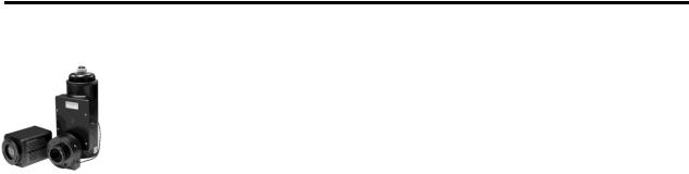
Standard Components
All Spec-10 systems consist of standard hardware and software as well as appropriate interface hardware for your computer system. Some systems also include optional hardware.
Optional System Components
Optional items include an internal shutter (LN-cooled detectors only), spectrometer mount adapters, dual digitization capability, and a Caron Chilled Coolant Circulator for TE-cooled systems.
Figure 1. Standard Components
11

12 |
Spec-10 System Manual |
Version 2.F |
|
|
|
Application Software
Spec-10 detectors run under WinSpec/32, Princeton Instruments' 32-bit Windows software package for spectroscopy. WinSpec/32 provides comprehensive spectral acquisition, display, processing, and archiving functions — so you can perform complete data acquisition and analysis without having to rely upon third-party software. WinSpec gives you the ability to run automatic spectrometer control and calibration routines, as well as to move to any spectral window or change gratings without having to recalibrate. WinSpec also facilitates snap-ins to permit easy user customization of any function or sequence. Windows DLLs are available to allow you to write your own software, making integration of the detection system into larger experiments or instruments a straightforward endeavor.
About this Manual
Manual Organization
This manual provides the user with all the information needed to install a Spec-10 detector and place it in operation. Topics covered include a detailed description of the detector, installation, cleaning, specifications and more.
Note: The general identifier "ST-133" is used for both the ST-133A Controller and the ST-133B Controller. Where there is a difference, the specific identifier is used.
Chapter 1, Introduction briefly describes the Spec-10 family of detectors; details the structure of this manual; and documents environmental, storage, and cleaning requirements.
Chapter 2, System Component Descriptions provides descriptions of each system component.
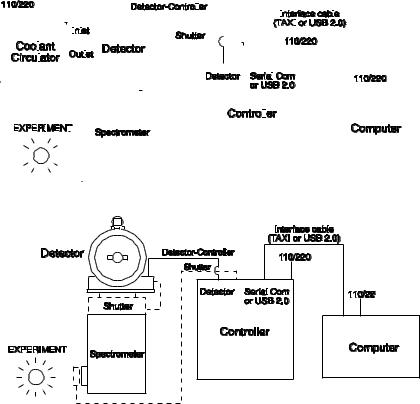
Chapter 3, Installation Overview cross-references system setup actions with the relevant manuals and/or manual pages. It also contains system layout diagrams.
Chapter 4, System Setup provides detailed directions for mounting the detector to a spectrometer and for interconnecting the system components.
Chapter 5, Operation includes a simple procedure for verifying system operation and discusses operational considerations associated with exposure, readout, and digitization.
Chapter 6, Advanced Topics discusses standard timing modes (Free Run, External Sync, and Continuous Cleans), Fast and Safe triggering modes, and TTL control.
Chapter 7, Troubleshooting provides courses of action to take if you should have problems with your system.
Appendix A, Specifications includes computer, controller and detector specifications.
Appendix B, Outline Drawings includes outline drawings of the Spec-10 detectors and the ST-133A and ST-133B Controllers.
Appendix C, Spectrometer Adapters provides mounting instructions for the spectrometer adapters available for Spec-10 detectors.

Chapter 1 |
Introduction |
13 |
|
|
|
Appendix D, USB 2.0 Limitations covers the currently known limitations associated with operating under the USB 2.0 interface.
Declarations of Conformity contains the Declarations of Conformity for Spec-10 systems (LN-, NTE-, NTE 2-, TEA-, XTE-cooled and lifetime vacuum XP).
Warranty and Service provides the Princeton Instruments warranty and customer support contact information.
Safety Related Symbols Used in this Manual
Caution! The use of this symbol on equipment indicates that one or more nearby items should not be operated without first consulting the manual. The same symbol appears in the manual adjacent to the text that discusses the hardware item(s) in question.
Warning! Risk of electric shock! The use of this symbol on equipment indicates that one or more nearby items pose an electric shock hazard and should be regarded as potentially dangerous. This same symbol appears in the manual adjacent to the text that discusses the hardware item(s) in question.
Grounding and Safety
The ST-133 is of Class I category as defined in IEC Publication 348 (Safety Requirements for Electronic Measuring Apparatus). It is designed for indoor operation only. Before turning on the controller, the ground prong of the powercord plug must be properly connected to the ground connector of the wall outlet. The wall outlet must have a third prong, or must be properly connected to an adapter that complies with these safety requirements.
WARNING! If the equipment is damaged, the protective grounding could be disconnected. Do not use  damaged equipment until its safety has been verified by authorized personnel.
  Disconnecting the protective earth terminal, inside or outside the apparatus, or any
  tampering with its operation is also prohibited.
Inspect the supplied powercord. If it is not compatible with the power socket, replace the cord with one that has suitable connectors on both ends.
WARNING! Replacement powercords or power plugs must have the same polarity as that of the original ones to avoid hazard due to electrical shock.
ESD Precautions
The CCD and other system electronics are extremely sensitive to electrostatic discharge (ESD). To avoid permanently damaging the system, please observe the following precautions:
When using high-voltage equipment (such as an arc lamp) with your Spec-10 system, be sure to turn the controller power on last and power the controller off first.
14 |
Spec-10 System Manual |
Version 2.F |
|
|
|
Use caution when triggering high-current switching devices (such as an arc lamp) near your system. Transient voltage spikes can permanently damage the CCD. If electrically noisy devices are present, an isolated, conditioned power line or dedicated isolation transformer is highly recommended.
Never connect or disconnect any cable while the Spec-10 system is powered on. An unconnected cable segment can become electrically charged and can damage the CCD if reconnected.
Connect the detector-controller cable to the controller before connecting the cable to the detector.
Disconnect the detector-controller cable from the detector before disconnecting it from the controller.
Additional Precautions
Detector and Controller
If the equipment is damaged, the protective grounding could be disconnected. Do not use damaged equipment until its safety has been verified by authorized personnel. Disconnecting the protective earth terminal, inside or outside the apparatus, or any tampering with its operation is also prohibited. Never impede airflow through the equipment by obstructing the air vents. Allow at least oneinch air space around any vent.
Do not "mix and match" detectors and controllers.
Prevent array saturation while data is not being acquired by completely closing the entrance slit to the spectrometer (especially when a shutter is not used).
Protect a UV-scintillator-coated CCD from excessive exposure to UV radiation. This radiation slowly bleaches the scintillator, reducing sensitivity.
If an LN-cooled detector is being operated under high humidity conditions, periodically clean the outside of the valves so ice buildup does not prevent the valves from venting normally.
Operating liquid-assist TE-cooled detectors in high humidity environments can produce condensation inside the detector's electronic enclosure. Damage from humid condensation may not be covered by the product warranty.
Shutter
To prevent damage to the shutter or shutter drive circuitry, always turn the controller off before connecting or disconnecting the shutter cable.
Spectrometer Support
Princeton Instruments offers extensive support for spectrometer integration, including fiberoptic accessories, lenses, lens mounts, f# matchers, and spectrometer flanges. The Spec-10 detector can be coupled to Roper Scientific’s entire line of Acton Research spectrometers, providing fully integrated instruments that offer automated software control of both spectrometer and detector. Adapters are also available for most other spectrometers.

Chapter 1 |
Introduction |
15 |
|
|
|
Enhancement Coatings
To raise the QE of these spectrometric CCDs, Princeton Instruments offers a variety of enhancement coatings. For higher sensitivity in the NIR, deep-depletion devices are also available. Princeton Instruments has even worked with a device manufacturer to successfully minimize the etalon effect (fringing) that typically occurs when back-illuminated CCDs are used for NIR spectroscopy. This reduction is accomplished by making the back-illuminated CCD on thicker silicon, applying an AR coating optimized for the NIR, and processing the back surface in a proprietary way that helps break up the etalon effect.
Cleaning
WARNING! Turn off all power to the equipment and secure all covers before cleaning the units. Otherwise, damage to the equipment or injury to you could occur.
Detector and Controller
Although there is no periodic maintenance that must be performed on the Spec-10 detector or the controller, users are advised to wipe it down with a clean damp cloth from time to time. This operation should only be done on the external surfaces and with all covers secured. In dampening the cloth, use clean water only. No soap, solvents or abrasives should be used. Not only are they not required, but also they could damage the finish of the surfaces on which they are used.
Optical Surfaces
Optical surfaces may need to be cleaned due to the accumulation of atmospheric dust. We advise that the drag-wipe technique be used. This involves dipping a clean cellulose lens tissue into clean anhydrous methanol, and then dragging the dampened tissue over the optical surface to be cleaned. Do not allow any other material to touch the optical surfaces.
Repairs
Save the original packing materials. Because the Spec-10 detector system contains no user-serviceable parts, repairs must be done by Princeton Instruments. Should your system need repair, contact Princeton Instruments customer service for instructions (telephone, e-mail, and address information are provided on page 146 of this manual).
Use the original packing materials whenever shipping the system or system components.
16 |
Spec-10 System Manual |
Version 2.F |
|
|
|
This page intentionally left blank.
Chapter 2
System Component Descriptions
Spec-10 Detector
CCD Array: The Spec-10 system can be configured with a number of high performance, rectangular-format, frontand back-illuminated scientific grade CCDs (including eXcelonTM enabled back-illuminated CCDs), some of which are exclusive to Princeton Instruments. The arrays employ several design features engineered specifically towards optimizing performance parameters for spectroscopic experiments.
To raise the QE of these spectroscopic CCDs, Princeton Instruments offers a variety of enhancement coatings. For higher sensitivity in the NIR, deep-depletion devices are also available. Princeton Instruments has even worked with a device manufacturer to successfully minimize the etaloning effect (fringing) that typically occurs when backilluminated CCDs are used for NIR spectroscopy. This reduction is accomplished by manufacturing the CCD on thicker silicon, applying an AR coating optimized for NIR, and processing the back surface in a proprietary way that helps break up etaloning.
Window: The detector window is made of SI-UV fused silica quartz.
Internal Shutter: LN-cooled Spec-10 detectors can incorporate an internal shutter. It is important to realize the limitations of the shutter, including its mechanical lifetime (typically a million cycles or more). Avoid running the shutter unnecessarily and avoid using shorter exposure time and higher repetition rates than are required. If a shutter does stop working, contact the factory.
The shutter housing has a quartz shutter window unless otherwise specified. This window protects the shutter mechanism from external dust and humidity. However, a shutter window also causes a small signal loss. If this loss is significant, contact the factory to see if a windowless shutter housing is available. When there is no window, added caution must then be used in the handling and storage of the detector.
Connectors:
Controller: Power, control signals, and data are transmitted between the ST-133 and the Spec-10 detector via the 25-pin D connector located on the rear of the detector. The Detector-Controller cable is secured by a slide-latch mechanism. Controller power must be OFF before connecting to or disconnecting from this connector.
Shutter: LEMO connector for driving an internal shutter. Controller power must be OFF before connecting to or disconnecting from this connector.
Fan: (NTE/NTE 2/XP/XTE only) There may be a fan located inside the detector's back panel. Its purpose is:
to remove heat from the Peltier device that cools the CCD array and
to cool the electronics.
17
18 |
Spec-10 System Manual |
Version 2.F |
|
|
|
An internal Peltier device directly cools the cold finger on which the CCD is mounted. The heat produced by the Peltier device is then removed by the air drawn into the detector by the internal fan and exhausted through the side covers. The fan is always in operation and air cooling of both the Peltier and the internal electronics takes place continuously. The fan is designed for low-vibration and does not adversely affect the image. For the fan to function properly, free circulation must be maintained between the rear of the detector and the laboratory atmosphere.
Coolant Ports: Several of the thermoelectrically-cooled detectors are available with optional liquid-assisted or liquid-only cooling. Two coolant ports are provided on the sides of these detectors. These quick-disconnect ports require 1/4" thin-wall plastic tubing or 3/8" I.D. thick-wall PVC tubing, depending on the Spec-10 model. Instructions for setting up coolant flow are provided on page 40.
Dewar: LN-cooled detectors are available in both the standard side-on and the end-on configuration. The Dewar for the standard side-on holds 1.7 liters of liquid nitrogen (LN). The Dewar for the end-on detector holds 2.2 liters of liquid nitrogen (LN).
An "all-directional" Dewar is available from Princeton Instruments. This Dewar can operate in any angular orientation but holds about half as much LN as the standard Dewar (~0.85 liters). This reduced capacity translates to roughly half the hold time, as well.
Note: There is no simple way to determine if you have been shipped an all-directional system simply by observing the detector. If you are uncertain, check the shipping paperwork to verify that your Dewar is an all-directional model.
Adapters: A variety of spectrograph adapters are available from Princeton Instruments. Refer to Appendix C for information about mounting these adapters to your spectrometer and detector.
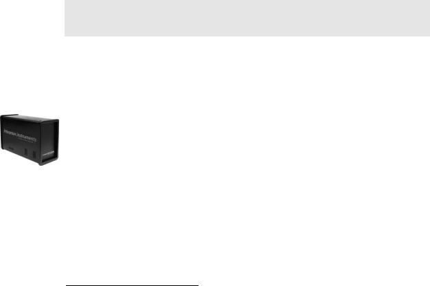
ST-133 Controller
Electronics: The ST-133 controller is a compact, high performance CCD Detector Controller for operation with Princeton Instruments brand* detectors. Designed for high speed and high performance image acquisition, the ST-133 offers data transfer at speeds up to 5 megapixel per second and standard video output for focusing and alignment. A variety of A/D converters are available to meet different speed and resolution requirements.
In addition to containing the power supply, the controller contains the analog and digital electronics, scan control and exposure timing hardware, and controller I/O connectors, all mounted on user-accessible plug-in modules. This highly modularized design gives flexibility and allows for convenient servicing.
*The ST-133 controller must be factory configured for operation with an LN detector. For this reason, a controller purchased for operation with an LN detector can only be used with an LN detector. Similarly, a controller purchased for operation with a TE, NTE, or XTE detector cannot be used with an LN detector.

Chapter 2 |
System Component Descriptions |
19 |
|
|
|
POWER Switch and Indicator: The power
switch location and characteristics depend on the version of ST-133 Controller that was shipped with your system. In some versions, the power switch is located on the on the front panel and has an integral indicator LED that lights whenever the ST-133 is powered. In other versions, the power switch is located on the back of the
ST-133 and does not include an indicator LED. Figure 2 shows the two locations.
Rear Panel Connectors: There are three controller board slots. Two are occupied by the plug-in cards that provide various controller
functions. The third, covered with a blank panel, is reserved for future development. The left-most plug-in card is the Analog/Control module. Adjacent to it is the Interface Control module. Both modules align with top and bottom tracks and mate with a passive back-plane via a 64-pin DIN connector. For proper operation, the location of the modules should not be changed. Each board is secured by two screws that also ground each module’s front panel. The connectors and functions located on the rear panel are further are described on the following page. Removing and inserting boards is described in Chapter 7, pages 89-90
WARNING! To minimize the risk of equipment damage, a module should never be removed or installed when the system is powered.
The Analog/Control Module, which should always be located in the left-most slot, provides the following functions:
|
Pixel A/D conversion |
Timing and synchronization of readouts |
|
|
CCD scan control |
|
Temperature control |
|
Exposure control |
|
Video output control |
The Interface Control Module, which should always be located in the center slot, provides the following functions:
TTL In/Out Programmable Interface
Communications Control (TAXI or USB 2.0 protocol)
WARNING! Always turn the power off at the Controller before connecting or disconnecting any cable that interconnects the detector and controller or serious damage to the CCD may result. This damage is NOT covered by the manufacturer’s warranty. 
.

20 |
Spec-10 System Manual |
Version 2.F |
|
|
|
Rear Panel Features:
The descriptions of the rear panel connectors are keyed to the accompanying figure. Depending on your system, either the TAXI or the USB 2.0 Interface Control Module will be installed in the second from the left slot (as you face the rear of the ST-133). In the Figure 3, the TAXI module is shown in that position.
# |
Feature |
|
1 |
Temperature Lock LED: Indicates that the |
|
|
temperature control loop has locked and that |
|
|
the temperature of the CCD array will be stable |
|
|
to within 0.05 C. |
|
2 |
Video/Aux Output: If labeled Video, composite |
|
|
video output is provided at this connector. The |
|
|
amplitude is 1 V pk-pk and the source impedance |
|
|
is 75 . Note that video output is not currently |
|
|
supported under USB 2.0. If labeled Aux, this |
|
|
output is reserved for future use. |
|
3 |
External Sync Input: TTL input that has a 10 |
|
|
k pullup resistor. Allows data acquisition and |
|
|
readout to be synchronized with external events. |
|
|
Through software, positive or negative (default) |
|
|
triggering can be selected. |
|
4 |
Output: WinSpec/32 (ver. 2.4 and |
|
|
higher) software-selectable NOT SCAN or |
|
|
SHUTTER signal. Default is SHUTTER. |
|
|
|
Figure 3. ST-133 Rear Panel Callouts |
5 |
Output: Initially HIGH. Changes state |
11 Fan: Cools the controller electronics. Runs |
|
on completion of cleaning cycles before the first |
continuously when the controller is turned on. |
|
exposure. |
|
6 |
Zero Adjustment: Bias potentiometers control |
12 Shutter Setting Selector: Sets the shutter hold |
|
the offset values of the Fast (F) and Slow (S) A/D |
voltage. Dial is correctly set at the factory for the |
|
converters. Preadjusted at factory. If |
detector’s internal shutter if one is present. Refer |
|
potentiometers are not present, bias may be |
to Table 4, on page 36 for the shutter setting |
|
software-settable. |
appropriate to your system. |
7 |
Detector Connector: Transmits control |
13 Remote Shutter Connector: Provides shutter-drive |
|
information to the detector and receives data back |
and hold voltages for a Princeton Instruments 25 mm |
|
from the detector via the Detector-Controller cable. |
external shutter (typically, an entrance slit shutter). |
8 |
TTL In/Out: User-programmable interface |
14 Power Input Module: Contains the powercord |
|
with eight input bits and eight output bits that |
socket and two fuses. Depending on the ST-133 |
|
can be written to or polled for additional |
version, the power switch may be located directly |
|
control or functionality. Output is not currently |
above the power module. |
|
supported under USB 2.0. See Chapter 6. |
|
9 |
AUX Output: Reserved for future use. |
15 Fuse/Voltage Label: Displays the controller’s |
|
|
power and fuse requirements. This label may |
|
|
appear below the power module. |
10 |
Serial COM Connector: Provides two-way serial |
16 USB 2.0 Connector: Provides two-way serial |
|
communication between the controller and the |
communication between the controller and the host |
|
host computer. Uses TAXI protocol. |
computer. Uses USB 2.0 protocol. |
Chapter 2 |
System Component Descriptions |
21 |
|
|
|
Cables
Detector-Controller: The standard 10' (3 m) cable (6050-0321 for TEor 6050-0361 for LN-cooled detector) has DB-25 connectors with slide-latch locking hardware. This cable interconnects the Detector connector on the rear of the ST-133 with the Detector connector on the rear of the Spec-10 detector. The Detector-Controller cable is also available in 6', 15', 20', and 30' lengths.
Interface Cable: Depending on the system configuration, either a USB or a TAXI cable will be shipped.
TAXI: The standard 25' (7.6 m) cable (6050-0148-CE) has DB-9 Male connectors with screw-down locking hardware. The TAXI (Serial communication) cable interconnects the "Serial Com" connector on the rear of the ST-133 with the Princeton Instruments (RSPI) PCI card installed in the host computer. In addition to the standard length, this cable is available in 10', 50', 100', and 165' lengths. Also available are fiber optic adapters with fiber optic cables in 100, 300, and 1000 meter lengths.
USB 2.0: The standard 16.4' (5 m) cable (6050-0494) has USB connectors that interconnect the "USB 2.0" connector on the rear of the ST-133 with a USB card installed in the host computer.
Interface Card
PCI Card: The Princeton Instruments (RSPI) high speed PCI card is required when the system interface uses the TAXI protocol rather than USB 2.0. The PCI card plugs-into the host computer's motherboard and provides the serial communication interface between the host computer and the ST-133. Through WinSpec/32, the card can be used in either High Speed PCI or PCI(Timer) mode. High Speed PCI allows data transfer to be interrupt-driven and can give higher performance in some situations. PCI(Timer) allows data transfer to be controlled by a polling timer.
USB 2.0 Card: This interface card is required when the system interface uses the USB 2.0 protocol rather the TAXI protocol and the computer does not have native USB 2.0 support. The USB 2.0 card plugs-into the host computer's motherboard and provides the communication interface between the host computer and the ST-133. The USB 2.0 PCI card (70USB90011) by Orange Micro is recommended for desktop computers; the SIIG, Inc. USB 2.0 PC Card, Model US2246 is recommended for laptop computers. See www.orangemicro.com or www.siig.com, respectively, for more information.
Application Software
WinSpec/32: Princeton Instruments' 32-bit Windows® software package for spectroscopy. It provides stand-alone comprehensive spectral acquisition, display, processing, and archiving functions. WinSpec gives you the ability to run automatic spectrometer control and calibration routines, as well as to move to any spectral window or change gratings without having to recalibrate. WinSpec also features snap-ins and macro record capability to permit easy user customization of any function or sequence.

22 |
Spec-10 System Manual |
Version 2.F |
|
|
|
PVCAM: A standard software interface for cooled PDA, FPA, and CCD detectors from Roper Scientific. It is a library of functions that can be used to control and acquire data from the detector when a custom application is being written. For example, in the case of Windows, PVCAM is a dynamic link library (DLL). Also, it should be understood that PVCAM is solely for detector control and image acquisition, not for image processing. PVCAM places acquired images into a buffer, where they can then be manipulated using either custom written code or by extensions to other commercially available image processing packages.
Scientific Imaging ToolKit™ (SITK™): A collection of LabVIEW® VIs for scientific detectors and spectrographs. This third party software can be purchased from Princeton Instruments.
User Manuals
Spec-10 System User Manual: This manual describes how to install and use the Spec-10 system components.
WinSpec/32 User Manual: This manual describes how to install and use the application program. A PDF version of this manual is provided on the installation CD. Additional information is available in the program's on-line help.

Chapter 3
Installation Overview
The list and diagrams below briefly describe the sequence of actions required to hookup your system and prepare to gather data. Refer to the indicated references for more detailed information.
|
Action |
Reference |
|
|
|
1. |
If the system components have not already been unpacked, unpack |
Chapter 4 System Setup, |
|
them and inspect their carton(s) and the system components for in- |
page 25 |
|
transit damage. |
|
|
|
|
2. |
Verify that all system components have been received. |
Chapter 4 System Setup, |
|
|
page 25 |
|
|
|
3. |
If the components show no signs of damage, verify that the |
Chapter 4 System Setup, |
|
appropriate voltage settings have been selected for the Controller. |
page 28 |
|
|
|
4. |
If the WinSpec/32 software is not already installed in the host |
WinSpec/32 manual |
|
computer, install it. |
|
|
|
|
5. |
If the appropriate interface card is not already installed in the host |
Chapter 4 System Setup, |
|
computer, install it. |
page 29 (TAXI-PCI) or |
|
|
page 30 (USB) |
|
|
|
6. |
Mount the Detector to the spectrometer. |
Chapter 4 System Setup, |
|
|
page 33 |
|
|
|
7. |
With the Controller power turned OFF, connect the Detector- |
Chapter 4 System Setup, |
|
Controller cable to the DETECTOR connector on the rear of the |
page 37 |
|
Controller. Adjust the slide latch so the cable connection is locked. |
Chapter 15 Troubleshooting, |
|
|
page 91 |
|
|
|
8. |
With the Controller power turned OFF, connect the Detector- |
Chapter 4 System Setup, |
|
Controller cable to the appropriate connector on the rear of the |
page 37 |
|
Detector. Then tighten down the locking hardware (lock screws or |
|
|
slide-latch depending on detector and cable used). |
|
|
|
|
9. |
With the Controller and computer power turned OFF, connect the |
Chapter 4 System Setup, |
|
interface cable (TAXI or USB) to the Controller and the interface |
page 37 |
|
card in the host computer. Then tighten down the locking hardware. |
|
|
|
|
10. With the Controller power turned OFF, connect the Controller |
|
|
|
power cable to the rear of the controller and to the power source. |
|
|
|
|
11. Turn the Controller ON. |
|
|
|
|
|
23
24 |
|
|
|
|
|
|
|
|
|
|
|
|
|
|
|
|
|
|
|
|
|
|
|
|
|
|
|
|
|
|
|
|
|
|
|
|
|
|
|
|
|
Spec-10 System Manual |
|
|
|
|
|
|
|
|
|
Version 2.F |
||||||||||||||||||||||||||||||||||||||||||||||||||||||
|
|
|
|
|
|
|
|
|
|
|
|
|
|
|
|
|
|
|
|
|
|
|
|
|
|
|
|
|
|
|
|
|
|
|
|
|
|
|
|
|
|
|
|
|
|
|
|
|
|
|
|
|
|
|
|
|
|
|
|
|
|
|
|
|
|
|
|
|
|
|
|
|
|
|
|
|
|
|
|
|
|
|
|
|
|
|
|
|
|
|
|
|
|
|
|
|
|
|
|
|
|
|
|
|
|
|
|
|
|
|
|
|
|
|
|
|
|
|
|
|
|
|
|
|
|
|
|
|
|
|
|
|
|
|
|
|
|
|
|
|
|
|
|
|
|
|
|
|
|
|
|
|
|
|
|
|
|
|
|
|
|
|
|
|
|
|
|
|
|
|
|
|
|
|
|
|
|
|
|
|
|
|
|
|
|
|
|
|
|
|
|
|
|
|
|
|
|
|
|
|
|
|
|
|
|
|
|
|
|
|
|
|
|
|
|
|
|
|
|
|
|
|
|
|
|
|
|
|
|
|
|
|
|
|
|
|
|
Action |
|
|
|
|
|
|
|
Reference |
|
|||||||||||||||||||||||||||||||||||||||||||||||||||||||||||||||||||||||||
|
|
|
|
|
|
|
|
|
|
|
|
|
|
|
|
|
|
|
|
|
|
|
|
|
|
|
|
|
|
|
|
|
|
|
|
|
|
|
|
|
|
|
|
|
|
|
|
|
|
|
|
|
|
|
|
|
|
|
|
|
|
|
|
|
|
|
|
|
|
|
|
|
|
|
|
|
|
|
|
|
|
|
|
|
|
|
|
|
|
|
|
|
|
|
|
|
|
|
|
|
|
|
|
|
|
|
|
12. |
Turn on the computer and begin running WinSpec/32. When the |
|
|
Chapter 4 System Setup, |
|
||||||||||||||||||||||||||||||||||||||||||||||||||||||||||||||||||||||||||||||||||||||||||||||||||||
|
|
computer boots, you may be asked for the location of the interface |
|
|
page 29 (PCI drivers) or |
|
||||||||||||||||||||||||||||||||||||||||||||||||||||||||||||||||||||||||||||||||||||||||||||||||||||
|
|
drivers. |
|
|
page 30 (USB drivers) |
|
||||||||||||||||||||||||||||||||||||||||||||||||||||||||||||||||||||||||||||||||||||||||||||||||||||
|
|
|
|
|
|
|
|
|
|
|
|
|
|
|
|
|
|
|
|
|
|
|
|
|
|
|
|
|
|
|
|
|
|
|
|
|
|
|
|
|
|
|
|
|
|
|
|
|
|
|
|
|
|
|
|
|
|
|
|
|
|
|
|
|
|
|
|
|
|
|
|
|
|
|
|
|
|
|
|
|
|
|
|
|
|
|
|
|
|
|
|
|
|
|
|
|
WinSpec/32 manual |
|
||||||||
|
|
|
|
|
|
|
|
|
|
|
|
|
|
|
|
|
|
|
|
|
|
|
|
|
|
|
|
|
|
|
|
|
|
|
|
|
|
|
|
|
|
|
|
|
|
|
|
|
|
|
|
|
|
|
|
|
|
|
|
|
|
|
|
|
|
|
|
|
|
|
|
|
|
|
|
|
|
|
|
|
|
|
|
|
|
|
|
|
|
|
|
|
|
|
|
|
|
|
|
|
|
|
|
|
|
|
|
13. |
In WinSpec/32, run the Camera Detection wizard or load the |
|
|
Chapter 5 Operation |
|
||||||||||||||||||||||||||||||||||||||||||||||||||||||||||||||||||||||||||||||||||||||||||||||||||||
|
|
defaults from the controller. |
|
|
WinSpec/32 manual |
|
||||||||||||||||||||||||||||||||||||||||||||||||||||||||||||||||||||||||||||||||||||||||||||||||||||
|
|
|
|
|
|
|
|
|
|
|
|
|
|
|
|
|
|
|
|
|
|
|
|
|
|
|
|
|
|
|
|
|
|
|
|
|
|
|
|
|
|
|
|
|
|
|
|
|
|
|
|
|
|
|
|
|
|
|
|
|
|
|
|
|
|
|
|
|
|
|
|
|
|
|
|
|
|
|
|
|
|
|
|
|
|
|
|
|
|
|
|
|
|
|
|
|
|
|||||||||
|
|
|
|
|
|
|
|
|
|
|
|
|
|
|
|
|
|
|
|
|
|
|
|
|
|
|
|
|
|
|
|
|
|
|
|
|
|
|
|
|
|
|
|
|
|
|
|
|
|
|
|
|
|
|
|
|
|
|
|
|
|
|
|
|
|
|
|
|
|
|
|
|
|
|
|
|
|
|
|
|
|
|
|
|
|
|
|
|
|
|
|
|
|
|
|
|
|
|
|
|
|
|
|
|
|
|
|
14. |
Set the target array temperature. |
|
|
Chapter 5 Operation, |
|
||||||||||||||||||||||||||||||||||||||||||||||||||||||||||||||||||||||||||||||||||||||||||||||||||||
|
|
|
|
|
|
|
|
|
|
|
|
|
|
|
|
|
|
|
|
|
|
|
|
|
|
|
|
|
|
|
|
|
|
|
|
|
|
|
|
|
|
|
|
|
|
|
|
|
|
|
|
|
|
|
|
|
|
|
|
|
|
|
|
|
|
|
|
|
|
|
|
|
|
|
|
|
|
|
|
|
|
|
|
|
|
|
|
|
|
|
|
|
|
|
|
|
page 54 |
|
||||||||
|
|
|
|
|
|
|
|
|
|
|
|
|
|
|
|
|
|
|
|
|
|
|
|
|
|
|
|
|
|
|
|
|
|
|
|
|
|
|
|
|
|
|
|
|
|
|
|
|
|
|
|
|
|
|
|
|
|
|
|
|
|
|
|
|
|
|
|
|
|
|
|
|
|
|
|
|
|
|
|
|
|
|
|
|
|
|
|
|
|
|
|
|
|
|
|
|
|
|
|
|
|
|
|
|
|
|
|
15. |
If the system is cooled by coolant circulation, make the tubing |
|
|
Chapter 4 System Setup, |
|
||||||||||||||||||||||||||||||||||||||||||||||||||||||||||||||||||||||||||||||||||||||||||||||||||||
|
|
connections between the coolant circulator and the detector. |
|
|
page 40 |
|
||||||||||||||||||||||||||||||||||||||||||||||||||||||||||||||||||||||||||||||||||||||||||||||||||||
|
|
|
|
|
|
|
|
|
|
|
|
|
|
|
|
|
|
|
|
|
|
|
|
|
|
|
|
|
|
|
|
|
|
|
|
|
|
|
|
|
|
|
|
|
|
|
|
|
|
|
|
|
|
|
|
|
|
|
|
|
|
|
|
|
|
|
|
|
|
|
|
|
|
|
|
|
|
|
|
|
|
|
|
|
|
|
|
|
|
|
|
|
|
|
|
|
|
|
|
|
|
|
|
|
|
|
|
16. |
If the system is cryogenically cooled, fill the Dewar. |
|
|
Chapter 5 Operation, |
|
||||||||||||||||||||||||||||||||||||||||||||||||||||||||||||||||||||||||||||||||||||||||||||||||||||
|
|
|
|
|
|
|
|
|
|
|
|
|
|
|
|
|
|
|
|
|
|
|
|
|
|
|
|
|
|
|
|
|
|
|
|
|
|
|
|
|
|
|
|
|
|
|
|
|
|
|
|
|
|
|
|
|
|
|
|
|
|
|
|
|
|
|
|
|
|
|
|
|
|
|
|
|
|
|
|
|
|
|
|
|
|
|
|
|
|
|
|
|
|
|
|
|
page 41 |
|
||||||||
|
|
|
|
|
|
|
|
|
|
|
|
|
|
|
|
|
|
|
|
|
|
|
|
|
|
|
|
|
|
|
|
|
|
|
|
|
|
|
|
|
|
|
|
|
|
|
|
|
|
|
|
|
|
|
|
|
|
|
|
|
|
|
|
|
|
|
|
|
|
|
|
|
|
|
|
|
|
|
|
|
|
|
|
|
|
|
|
|
|
|
|
|
|
|
|
|
|
|
|
|
|
|
|
|
|
|
|
17. |
When the system reaches temperature lock, wait an additional 30 |
|
|
Chapter 5 Operation, |
|
||||||||||||||||||||||||||||||||||||||||||||||||||||||||||||||||||||||||||||||||||||||||||||||||||||
|
|
minutes and then begin acquiring data in focus mode. |
|
|
page 49 |
|
||||||||||||||||||||||||||||||||||||||||||||||||||||||||||||||||||||||||||||||||||||||||||||||||||||
|
|
|
|
|
|
|
|
|
|
|
|
|
|
|
|
|
|
|
|
|
|
|
|
|
|
|
|
|
|
|
|
|
|
|
|
|
|
|
|
|
|
|
|
|
|
|
|
|
|
|
|
|
|
|
|
|
|
|
|
|
|
|
|
|
|
|
|
|
|
|
|
|
|
|
|
|
|
|
|
|
|
|
|
|
|
|
|
|
|
|
|
|
|
|
|
|
|
|
|
|
|
|
|
|
|
|
|
18. |
Adjust the focus for the best spectral lines. If you are using |
|
|
Chapter 5 Operation, |
|
||||||||||||||||||||||||||||||||||||||||||||||||||||||||||||||||||||||||||||||||||||||||||||||||||||
|
|
WinSpec/32, you may want to use the Focus Helper function for this |
|
|
page 49 |
|
||||||||||||||||||||||||||||||||||||||||||||||||||||||||||||||||||||||||||||||||||||||||||||||||||||
|
|
purpose. |
|
|
|
|
|
|
|
|
|
|
|
|
||||||||||||||||||||||||||||||||||||||||||||||||||||||||||||||||||||||||||||||||||||||||||||
|
|
|
|
|
|
|
|
|
|
|
|
|
|
|
|
|
|
|
|
|
|
|
|
|
|
|
|
|
|
|
|
|
|
|
|
|
|
|
|
|
|
|
|
|
|
|
|
|
|
|
|
|
|
|
|
|
|
|
|
|
|
|
|
|
|
|
|
|
|
|
|
|
|
|
|
|
|
|
|
|
|
|
|
|
|
|
|
|
|
|
|
|
|
|
|
|
|
|
|
|
|
|
|
|
|
|
|
|
|
|
|
|
|
|
|
|
|
|
|
|
|
|
|
|
|
|
|
|
|
|
|
|
|
|
|
|
|
|
|
|
|
|
|
|
|
|
|
|
|
|
|
|
|
|
|
|
|
|
|
|
|
|
|
|
|
|
|
|
|
|
|
|
|
|
|
|
|
|
|
|
|
|
|
|
|
|
|
|
|
|
|
|
|
|
|
|
|
|
|
|
|
|
|
|
|
|
|
|
|
|
|
|
|
|
|
|
|
|
|
|
|
|
|
|
|
|
|
|
|
|
|
|
|
|
|
|
|
|
|
|
|
|
|
|
|
|
|
|
|
|
|
|
|
|
|
|
|
|
|
|
|
|
|
|
|
|
|
|
|
|
|
|
|
|
|
|
|
|
|
|
|
|
|
|
|
|
|
|
|
|
|
|
|
|
|
|
|
|
|
|
|
|
|
|
|
|
|
|
|
|
|
|
|
|
|
|
|
|
|
|
|
|
|
|
|
|
|
|
|
|
|
|
|
|
|
|
|
|
|
|
|
|
|
|
|
|
|
|
|
|
|
|
|
|
|
|
|
|
|
|
|
|
|
|
|
|
|
|
|
|
|
|
|
|
|
|
|
|
|
|
|
|
|
|
|
|
|
|
|
|
|
|
|
|
|
|
|
|
|
|
|
|
|
|
|
|
|
|
|
|
|
|
|
|
|
|
|
|
|
|
|
|
|
|
|
|
|
|
|
|
|
|
|
|
|
|
|
|
|
|
|
|
|
|
|
|
|
|
|
|
|
|
|
|
|
|
|
|
|
|
|
|
|
|
|
|
|
|
|
|
|
|
|
|
|
|
|
|
|
|
|
|
|
|
|
|
|
|
|
|
|
|
|
|
|
|
|
|
|
|
|
|
|
|
|
|
|
|
|
|
|
|
|
|
|
|
|
|
|
|
|
|
|
|
|
|
|
|
|
|
|
|
|
|
|
|
|
|
|
|
|
|
|
|
|
|
|
|
|
|
|
|
|
|
|
|
|
|
|
|
|
|
|
|
|
|
|
|
|
|
|
|
|
|
|
|
|
|
|
|
|
|
|
|
|
|
|
|
|
|
|
|
|
|
|
|
|
|
|
|
|
|
|
|
|
|
|
|
|
|
|
|
|
|
|
|
|
|
|
|
|
|
|
|
|
|
|
|
|
|
|
|
|
|
|
|
|
|
|
|
|
|
|
|
|
|
|
|
|
|
|
|
|
|
|
|
|
|
|
|
|
|
|
|
|
|
|
|
|
|
|
|
|
|
|
|
|
|
|
|
|
|
|
|
|
|
|
|
|
|
|
|
|
|
|
|
|
|
|
|
|
|
|
|
|
|
|
|
|
|
|
|
|
|
|
|
|
|
|
|
|
|
|
|
|
|
|
|
|
|
|
|
|
|
|
|
|
|
|
|
|
|
|
|
|
|
|
|
|
|
|
|
|
|
|
|
|
|
|
|
|
|
|
|
|
|
|
|
|
|
|
|
|
|
|
|
|
|
|
|
|
|
|
|
|
|
|
|
|
|
|
|
|
|
|
|
|
|
|
|
|
|
|
|
|
|
|
|
|
|
|
|
|
|
|
|
|
|
|
|
|
|
|
|
|
|
|
|
|
|
|
|
|
|
|
|
|
|
|
|
|
|
|
|
|
|
|
|
|
|
|
|
|
|
|
|
|
|
|
|
|
|
|
|
|
|
|
|
|
|
|
|
|
|
|
|
|
|
|
|
|
|
|
|
|
|
|
|
|
|
|
|
|
|
|
|
|
|
|
|
|
|
|
|
|
|
|
|
|
|
|
|
|
|
|
|
|
|
|
|
|
|
|
|
|
|
|
|
|
|
|
|
|
|
|
|
|
|
|
|
|
|
|
|
|
|
|
|
|
|
|
|
|
|
|
|
|
|
|
|
|
|
|
|
|
|
|
|
|
|
|
|
|
|
|
|
|
|
|
|
|
|
|
|
|
|
|
|
|
|
|
|
|
|
|
|
|
|
|
|
|
|
|
|
|
|
|
|
|
|
|
|
|
|
|
|
|
|
|
|
|
|
|
|
|
|
|
|
|
|
|
|
|
|
|
|
|
|
|
|
|
|
|
|
|
|
|
|
|
|
|
|
|
|
|
|
|
|
|
|
|
|
|
|
|
|
|
|
|
|
|
|
|
|
|
|
|
|
|
|
|
|
|
|
|
|
|
|
|
|
|
|
|
|
|
|
|
|
|
|
|
|
|
|
|
|
|
|
|
|
|
|
|
|
|
|
|
|
|
|
|
|
|
|
|
|
|
|
|
|
|
|
|
|
|
|
|
|
|
|
|
|
|
|
|
|
|
|
|
|
|
|
|
|
|
|
|
|
|
|
|
|
|
|
|
|
|
|
|
|
|
|
|
|
|
|
|
|
|
|
|
|
|
|
|
|
|
|
|
|
|
|
|
|
|
|
|
|
|
|
|
|
|
|
|
|
|
|
|
|
|
|
|
|
|
|
|
|
|
|
|
|
|
|
|
|
|
|
|
|
|
|
|
|
|
|
|
|
|
|
|
|
|
|
|
|
|
|
|
|
|
|
|
|
|
|
|
|
|
|
|
|
|
|
|
|
|
|
|
|
|
|
|
|
|
|
|
|
|
|
|
|
|
|
|
|
|
|
|
|
|
|
|
|
|
|
|
|
|
|
|
|
|
|
|
|
|
|
|
|
|
|
|
|
|
|
|
|
|
|
|
|
|
|
|
|
|
|
|
|
|
|
|
|
|
|
|
|
|
|
|
|
|
|
|
|
|
|
|
|
|
|
|
|
|
|
|
|
|
|
|
|
|
|
|
|
|
|
|
|
|
|
|
|
|
|
|
|
|
|
|
|
|
|
|
|
|
|
|
|
Figure 4. System Diagram: TE-cooled Detector
Figure 5. System Diagram: LN-cooled Detector

Chapter 4
System Setup
Unpacking the System
During the unpacking, check the system components for possible signs of shipping damage. If there are any, notify Princeton Instruments and file a claim with the carrier. If damage is not apparent but detector or controller specifications cannot be achieved, internal damage may have occurred in shipment. Please save the original packing materials so you can safely ship the detector system to another location or return it to Princeton Instruments for repairs if necessary.
Checking the Equipment and Parts Inventory
Confirm that you have all of the equipment and parts required to set up the Spec-10 system. A complete system consists of:
Detector (TEor LN-cooled).
ST-133 Controller (TAXI or USB Interface Control Module)
Detector-Controller cable: DB25 to DB25 cable (6050-0321 is standard for TE-cooled detectors; 6050-0361 is standard for LN-cooled detectors).
Computer: Can be purchased from Princeton Instruments or provided by user.
WinSpec CD-ROM
User Manuals
Interface Dependent Components:
Controller-Computer Interface cable:
TAXI cable: DB9 to DB9 cable (6050-0148-CE is standard) or
USB cable: Five (5) meter cable (6050-0494) is standard
Interface Card: Princeton Instruments (RSPI) High Speed PCI Interface board for TAXI interface. USB 2.0 board for USB 2.0 interface is userprovided: native USB 2.0 support on the motherboard or USB 2.0 Interface Card (Orange Micro 70USB90011 USB2.0 PCI is recommended for desktop computers; SIIG, Inc. USB 2.0 PC Card, Model US2246 for laptop).
System Requirements
Environmental
Storage temperature: 55°C;
Operating environment temperature: 5ºC to +30ºC; for NTE/NTE 2 Detectors, the environment temperature range over which system specifications can be guaranteed is +18ºC to +23ºC
25

26 |
Spec-10 System Manual |
Version 2.F |
|
|
|
Relative humidity: <50% noncondensing. High humidity climates may require continuous flushing of the spectrometer’s exit port with nitrogen. If LN-cooled detectors are operated under high humidity conditions, ice-buildup could occur around the vent valves. Operating liquid-assist TE-cooled detectors in high humidity environments can produce condensation inside the detector's electronic enclosure. Damage from humid condensation may not be covered by the product warranty.
Ventilation
Detector: Allow at least one inch clearance for side and rear air vents. Where the detector is inside an enclosure, > 30 cfm air circulation and heat dissipation of 100W is required for TE air-cooled detectors.
ST-133: The internal fan is located at the right side of the rear panel behind an exhaust opening. Its purpose is simply to cool the controller electronics. This fan runs continuously whenever the controller is powered. Air enters the unit through ventilation openings on the side panels, flows past the warm electronic components as it rises, and is drawn out the rear of the controller by the fan. It is important that there be an adequate airflow for proper functioning. As long as both the controller’s intake ventilation openings and the fan exhaust opening aren’t obstructed, the controller will remain quite cool.
Coolant
WARNING! COOLANT IS HARMFUL IF SWALLOWED.
KEEP OUT OF REACH OF CHILDREN.
Spec-10 detectors with liquid-assisted cooling or liquid-only cooling require circulating coolant (50:50 mixture of ethylene glycol and water) for proper operation. The recommended flow rate and fluid pressure are: 2 liters/minute at 25 psig (maximum).
Power
Detector: The Spec-10 detector receives its power from the controller, which in turn plugs into a source of AC power.
ST-133: The ST-133 Controller can operate from any one of four different nominal line voltages: 100, 120, 220, or 240 V AC. Refer to the Fuse/Voltage label on the back of the ST-133 for fuse, voltage, and power consumption information.
Caution The plug on the line cord supplied with the system should be compatible with the linevoltage outlets in common use in the region to which the system is shipped. If the line cord plug is incompatible, a compatible plug should be installed, taking care to maintain the proper polarity to protect the equipment and assure user safety.

Chapter 4 |
System Setup |
27 |
|
|
|
Host Computer
Note: Computers and operating systems all undergo frequent revision. The following information is only intended to give an approximate indication of the computer requirements. Please contact the factory to determine your specific needs.
Requirements for the host computer depend on the type of interface, TAXI or USB 2.0, that will be used for communication between the ST-133 and the host computer. Those requirements are a listed below according to protocol.
TAXI Protocol:
2 GHz Pentium® 4 (or greater).
Windows® 95, Windows® 98SE, Windows® ME, Windows NT®, Windows® 2000, or Windows® XP operating system.
Note: WinSpec/32 versions 2.5.22-2.5.23 operate under Windows 2000 and later (32-bit only). Versions 2.5.25 and later operate under Windows XP (32-bit with SP3 or later) and Windows Vista® (32-bit).
Princeton Instruments (RSPI) High Speed PCI serial card (or an unused PCI card slot). Computers purchased from Princeton Instruments are shipped with the PCI card installed if High speed PCI was ordered.
Minimum of 1 GB RAM (or greater).
CD-ROM drive.
Hard disk with a minimum of 1 Gbyte available. A complete installation of the program files takes about 17-50 Mbytes and the remainder is required for data storage, depending on the number and size of images/spectra collected. Disk level compression programs are not recommended. Drive speed of 10,000 RPM recommended.
Super VGA monitor and graphics card supporting at least 65535 colors with at least
128 Mbyte of memory. Memory requirement is dependent on desired display resolution.
Two-button Microsoft compatible serial mouse or Logitech® three-button serial/bus mouse.
USB 2.0 Protocol:
2 GHz Pentium® 4 (or greater).
Windows 2000 (with Service Pack 4), Windows XP (with Service Pack 1) or later operating system.
Note: WinSpec/32 versions 2.5.22-2.5.23 operate under Windows 2000 and later (32-bit only). Versions 2.5.25 and later operate under Windows XP (32-bit with SP3 or later) and Vista (32-bit).
Native USB 2.0 support on the motherboard or USB Interface Card (Orange Micro 70USB90011 USB2.0 PCI is recommended for desktop computers; SIIG, Inc. USB 2.0 PC Card, Model US2246 for laptop).
Minimum of 1 GB RAM (or greater).
CD-ROM drive.
Hard disk with a minimum of 1 Gbyte available. A complete installation of the program files takes about 17-50 Mbytes and the remainder is required for data storage, depending on the number and size of images/spectra collected. Disk level compression programs are not recommended. Drive speed of 10,000 RPM recommended.
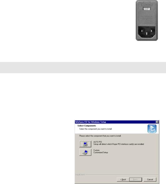
28 |
Spec-10 System Manual |
Version 2.F |
|
|
|
Super VGA monitor and graphics card supporting at least 65535 colors with at least
128 Mbyte of memory. Memory requirement is dependent on desired display resolution.
IEEE-488 GPIB port (required by DG535 Timing Generator, if present). May also be required by Spectrograph.
Mouse or other pointing device.
Verifying Controller Voltage Setting
The ST-133’s power requirements are discussed in Appendix A.
Note that the Spec-10 power requirements are entirely provided by the ST-133 via the Detector-Controller cable.
The Power Module on the rear of the Controller contains the voltage selector drum, fuses and the powercord connector. The appropriate voltage setting is set at the factory and can be seen on the back of the power module. Each setting actually defines a range and the setting that is closest to the actual line voltage should have been selected. The correct fuses for the country where the ST-133 is to be shipped are installed at the factory.
Figure 6. Controller
Power Module
Note: On ST-133s, the voltage ranges and fuse ratings may be printed above or below the power module.
To Check the Controller's Voltage Setting:
1.Look at the lower righthand corner on the rear of the Controller. The current voltage setting (100, 120, 220, or 240 VAC) is displayed on the Power Module.
2.If the setting is correct, continue with the installation. If it is not correct, follow the instructions on page 79 for changing the voltage setting and fuses.
Installing the Application Software
Installation is performed via the WinSpec/32 installation process. If you are installing WinSpec for the first time, you should run the installation before installing the interface card in the host computer. On the Select Components dialog box (see Figure 7), click on the AUTO PCI button to install the interface card drivers (Princeton Instruments (RSPI) PCI and Princeton Instruments USB drivers) and the most commonly installed program files. Select the Custom button if
you would like to choose among the available program files.
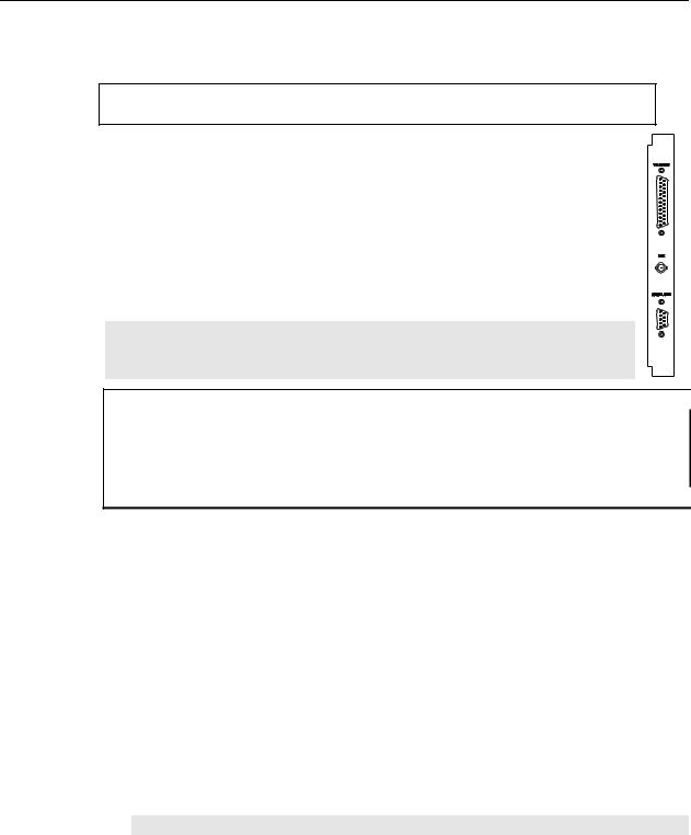
Chapter 4 System Setup 29
Setting up the Communication Interface
Setting up a PCI Interface
Administrator privileges are required under Windows NT®, Windows® 2000,
Windows® X, and Windows Vista® to install software and hardware.
A Princeton Instruments (RSPI) high speed PCI card must be installed in the host computer if the communication between computer and controller uses the TAXI protocol (i.e., the Interface Control Module installed in the ST-133 has a 9-pin SERIAL COM connector as shown in the figure at right). With TAXI protocol, the standard cable provided with an ST-133 is 7.6 meters (25 feet) (cable lengths up to 50 meters are available) and the digitization rate may be as high as 5 MHz.
A computer purchased from Princeton Instruments will be shipped with the PCI card already installed. Otherwise, a PCI card will be shipped with the system and you will have to install it in the host computer at your location.
Note: The PCI card can be installed and operated in any Macintosh having a PCI bus, allowing the ST-133 to be controlled from the Macintosh via IPLab™ software and the PI Extension.
Caution If using WinSpec/32 software, either High Speed PCI or PCI(Timer) can be the selected  Interface type. This selection is accessed on the Hardware Setup|Interface tab page. High Speed PCI allows data transfer to be interrupt-driven and gives the highest performance in some situations. PCI(Timer) allows data transfer to be controlled by a polling timer. This selection is recommended when there are multiple devices sharing the same interrupt.
To Install a PCI Serial Buffer Card in the Host Computer:
1.Review the documentation for your computer and PCI card before continuing with this installation.
2.To avoid risk of dangerous electrical shock and damage to the computer, verify that the computer power is OFF.
3.Remove the computer cover and verify that there is an available PCI slot.
4.Install the PCI card in the slot.
5.Make sure that the card is firmly seated and secure it.
6.Replace and secure the computer cover and turn on the computer only. If an error occurs at bootup, either the PCI card was not installed properly or there is an address or interrupt conflict. Refer to Chapter 7 "Troubleshooting", page 87 for instructions.
Note: The PCI card has no user-changeable jumpers or switches.

30 |
Spec-10 System Manual |
Version 2.F |
|
|
|
To Install the PCI Card Driver
The following information assumes that you have already installed the WinSpec/32 software.
1.After you have secured the PCI card in the computer and replaced the cover, turn the computer on.
2.At bootup, Windows will try to install the new hardware. If it cannot locate the driver, you will be prompted to enter the directory path, either by keyboard entry or by using the browse function.
If you selected AUTO PCI during the application software installation, WinSpec/32 automatically put the required INF file into the Windows/INF directory and put the PCI card driver file in the "Windows"/System32/ Drivers directory. Refer to Table 1 for the appropriate file names and locations.
Windows Version |
PCI INF Filename |
PCI Device Driver Name |
|
|
Located in "Windows"/INF |
Located in "Windows"/System32/Drivers |
|
|
|
||
|
directory* |
directory |
|
|
|
|
|
Windows® 2000 |
rspi.inf (in WINNT/INF, for |
rspipci.sys (in WINNT/System32/Drivers, |
|
and XP |
example) |
for example) |
|
|
|
|
|
Windows NT® |
N/A |
pi_pci.sys |
|
Windows® 95, 98, |
pii.inf |
pivxdpci.vxd |
|
and Windows® ME |
|
|
|
* The INF directory may be hidden. |
|
|
|
|
Table 1. PCI Driver Files and Locations |
|
|
Setting up a USB 2.0 Interface
Administrator privileges are required under Windows® 2000, Windows® XP and Windows Vista® to install software and hardware.
Your system has been configured to use the USB communication protocol if the Interface Control Module installed in the ST-133 has a USB 2.0 connector as shown in the figure at right). The advantages to the USB 2.0 interface are that it uses a much higher data transfer rate than many common serial data formats (such as the TAXI protocol) and it simplifies the connection to external devices. USB supports "plug and play" -- you do not need to be heavily involved in the setup process.
USB 2.0 Limitations
Maximum cable length is 5 meters (16.4 feet)
1 MHz is currently the upper digitization rate limit for the ST-133 Controller. Large data sets and/or long acquisition times may be subject to data overrun because of host computer interrupts during data acquisition.
USB 2.0 is not supported by the Princeton Instruments PC Interface Library (EZ-DLLS).
Some WinSpec 2.5.X features are not fully supported with USB 2.0. Refer to Appendix D, page 133, for more information.
 Loading...