

Page 1
Operation
Manual
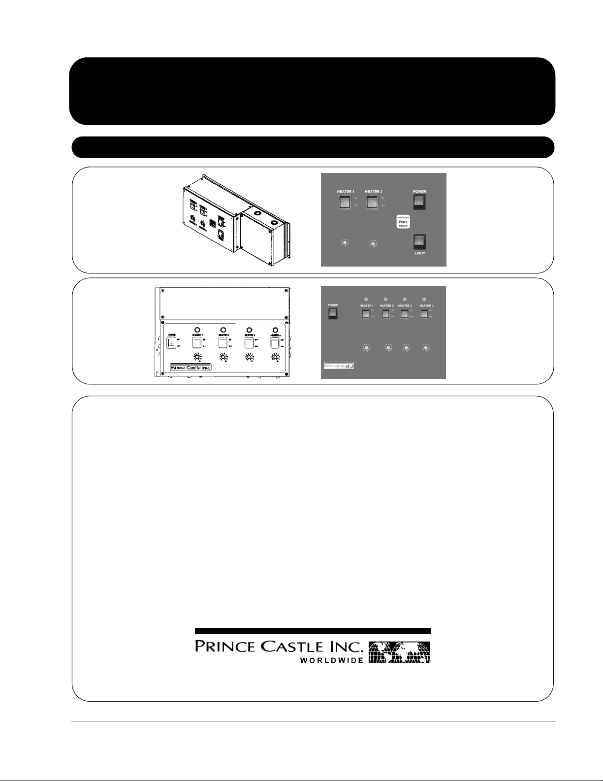
HPC-2A/2AF
HPC-4
Heater Panels
and Controllers
Product Identification
This product is warranted to be free from defects in material and/or
workmanship for a period of 1 year from date of original installation, not to
exceed 18 months from the date of manufacture.
Any component which proves to be faulty in material and/or workmanship
will be replaced or repaired (at the option of Prince Castle, Inc.) without
cost to the customer for parts and labor. This warranty covers on-location
service (i.e. trip charges and/or mileage). Travel mileage is limited to 100
miles (200 Kilometers) round trip (one trip warranty) from an authorized
service agency or its sub-service agency.
This warranty is subject to the following exceptions/conditions:
• Use of any non-genuine Prince Castle parts voids this warranty.
• All labor to be performed during regular work hours. Overtime premium
(the incremental amount) will be charged to the customer.
• Damage caused by carelessness, neglect and/or abuse (e.g., dropping,
tampering or altering parts, equipment damaged in shipment, by fire,
flood or an act of God) is not covered under this warranty.
• All problems due to operation at voltages other than that specified on
equipment nameplates are not covered by this warranty. Conversion to
correct voltage is the customer’s responsibility.
• This equipment must be serviced by Prince Castle Authorized Service
Agency or a Prince Castle Service Technician during the warranty
period.
355 East Kehoe Blvd. • Carol Stream, IL 60188 USA
Telephone: 630-462-8800 • Toll Free: 1-800-PCASTLE
Fax: 630-462-1460 • www.princecastle.com
LIMITED WARRANTY
TABLE OF CONTENTS
Product Identification . . . . . . . . . . . . . . . . . . . . . . . . . . . . . . . . . . . . 1
Specifications . . . . . . . . . . . . . . . . . . . . . . . . . . . . . . . . . . . . . . . . . . 2
Controller Installation . . . . . . . . . . . . . . . . . . . . . . . . . . . . . . . . . . . . 2
Heater Installation . . . . . . . . . . . . . . . . . . . . . . . . . . . . . . . . . . . . . . . 3
Start Up . . . . . . . . . . . . . . . . . . . . . . . . . . . . . . . . . . . . . . . . . . . . . . 4
Setting Recommendations . . . . . . . . . . . . . . . . . . . . . . . . . . . . . . . . 4
Cleaning . . . . . . . . . . . . . . . . . . . . . . . . . . . . . . . . . . . . . . . . . . . . . . 5
Exploded View and Parts List — Controllers . . . . . . . . . . . . . . . . . . 6, 7
Exploded View and Parts List — Heater Panels . . . . . . . . . . . . . . . . 8, 9
Wiring Diagrams . . . . . . . . . . . . . . . . . . . . . . . . . . . . . . . . . . . . . . . . 10-12
528-510revD Printed in USA 2/08 © 2008
Page 2
Heater Panels
and Controllers
Remove unit from carton and inspect for signs of damage. If there is damage to the unit:
1
• notify carrier within 24 hours of delivery.
• save carton and packaging material for inspection purposes.
• contact your local dealer, or if purchased directly, the Prince Castle Sales Department at 800-772-7853 or 630-462-8800 to arrange for a
replacement unit.
Specifications
Model Volts Max. Watts Hertz
HPC-2A/2AF 208/240 3900 50/60
HPC-4 208/240 7800 50/60
NOTE: Wattage depends on the size of the Heater Panels.
Controller Installation
Attach controller to the counter.
2
Attach the input power leads to the Controller Wiring Box. Connect
3
the power leads to the ter minals as shown in the Input Power
Terminal Block wiring label.
NOTE: The required voltage is 208 to 240 V, Single Phase. All
wiring to be in rigid or flexible conduit.
A. The wire connections are:
• L1 to Red
• L2 to Black
• Neutral to White
• Earth Ground to Green/Yellow
B. The panel will draw a maximum of 17 amps or 4100 Watts at 208 to
240 volts.
NOTE:The HPC-2 should be wired to a dedicated 25-amp circuit.
The HPC-4 should be wired to a dedicated 40-amp circuit.
All wiring to and from the controller must be in either
flexible or rigid metal conduit.
Connect the Green with yellow stripe ground wire to one of the
4
terminals shown in either of the Heater Terminal Block wiring
diagrams.
If the heater panel has a fluorescent light, connect the optional red
5
and orange leads for the fluorescent light to the terminals as
shown on the Light Terminal Block Wiring Diagram.
Turn the power switches on.
6
Turn the heater and light switches on.
7
Allow 45 minutes for the unit to warm up.
8
Printed in USA 2/08 © 2008 2 528-510revD
Page 3
Heater Installation
Heater Panels
and Controllers
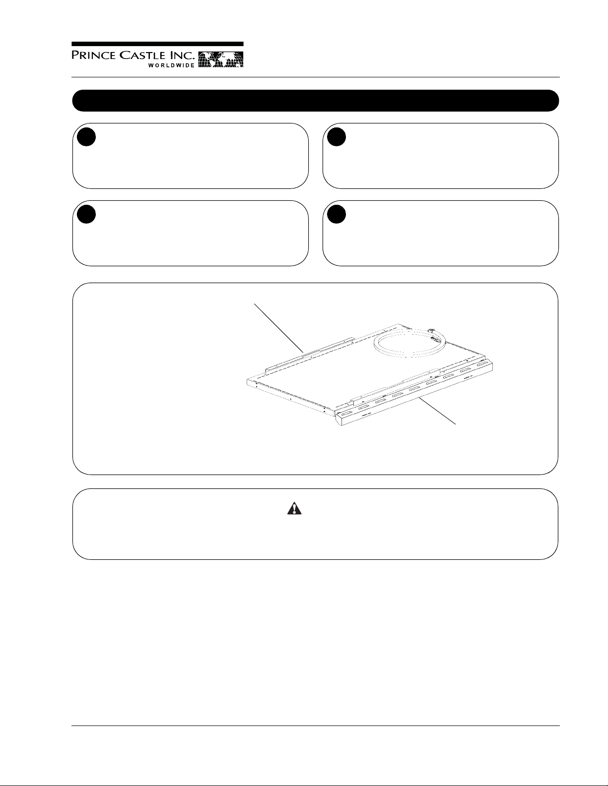
The brackets may either be mounted along the length or width of
1
the heater panel. For heater panels with lights, please allow 1/4" of
space above the light housing.
Remove mounting brackets from the heater panel and save the
2
screws.
1
1. Measure the mounting clips or remove
them and use them as a template when
mounting the panel.
Attach the mounting bracket to the mounting studs.
3
Position the heater panel to the mounting brackets and secure the
4
panel in place using the screws from step 2.
2. Light Housing depending on the model.
CAUTION
To reduce the risk of fire, this appliance should be installed in non-combustible surroundings only. There should be no combustible material
within 18 inches of the sides, front, or rear of the appliance or within 40 inches above the appliance. The appliance is to be mounted to noncombustible surfaces and radiate to non-combustible floors. These surfaces and floors should extend no less than 12 inches beyond the
appliance on all sides.
2
528-510revD 3 Printed in USA 2/08 © 2008
Page 4
Heater Panels
and Controllers
Start Up
NOTE: During the first few hours of operation, the heaters may produce a faint odor. This is normal and the odor will disappear after the first few hours
of use.
The heater panel and control are tested and calibrated at the factor y before shipment. However, temperature and climate changes during shipment
can allow the insulation in the heater panel to absorb moisture. During the first few hours the unit is in use, this moisture is driven from the insulation
while the insulation dries. The drying insulation often gives off a faint odor which will disappear after a few hours.
Setting Recommendations
Due to different airflow patterns found in each store, the actual heater settings for each store will be different. Air flow patterns are affected by drivethrough windows, open front and rear doors, air conditioning and make up air vents. All of these sources of air will draw heat away from the food. Below
are some recommended settings that may be used as a starting point before making final adjustments for each restaurant.
NOTE: A higher temperature setting will yield hotter food temperatures; however, the higher temperature will result in more moisture being driven from
the food. At the end of the maximum hold time, an ideal temperature setting will result in food that is at or above the minimum serving temperature and
still meets all quality requirements.
Distance versus Temperature Setting
Style 1
If the maximum distance between the heating surface and the surface
on which the food is placed is 20 inches, the recommended
adjustment range is from 7 to 10.
Distance versus Temperature Setting
Style 2
If the maximum distance between the heating surface and the surface
on which the food is placed is 15 inches, the recommended
adjustment range is from 4 to 7.
Temperature Adjustment
Each heater panel has a separate On/Off switch and a separate temperature adjustment. To adjust the temperature, put a blade screwdriver in the
temperature adjustment pot. Turn the pot counterclockwise to decrease the temperature and clockwise to increase the temperature. Stop turning the
pot when the blade is pointing at the desired value.
Printed in USA 2/08 © 2008 4 528-510revD
Page 5

Heater Panels
and Controllers
Cleaning
CAUTION
This unit is NOT water tight. Do NOT clean with Water Jet/Jet Spray. Before cleaning, make sure the power switches are in the OFF position.
Turn the power switch to the OFF position.
1
Allow the bin to cool down (approximately 35 minutes).
2
Wipe down surface with a damp cloth. Do not use a green Scotch
3
Bright pad, or unapproved cleaner.
Turn power on after all surfaces are dry.
4
528-510revD 5 Printed in USA 2/08 © 2008
Page 6

Heater Panels
and Controllers
Exploded View and Parts List — Controllers
HPC-2A/2AF
6
7
1
5
4
2
3
Ref. No. Description
1 428-440S Main PCB
2 78-218S Rocker Switch
3 78-184S Lighted Rocker Switch
4 528-359S Ballast Kit, HPC-2A
528-736S Ballast Kit, HPC-2AF
5 65-058S Relay Kit
6 65-048-07S Relay Kit, HPC-2A
65-048-10S Relay Kit, HPC-2AF
7 537-388S Transformer Assy, HPC-2A
528-443S Transformer Assy, HPC-2AF
Printed in USA 2/08 © 2008 6 528-510revD
Page 7

Exploded View and Parts List — Controllers
HPC-4
Heater Panels
and Controllers
8
3
2
Ref. No. Description
1 428-440S Main PCB
2 78-218S Rocker Switch
3 78-184S Lighted Rocker Switch
4 528-442S Ballast Kit
5 65-058S Relay Kit
6 65-048-07S Relay Kit
7 528-443S Transformer Kit
8 71-135-1S Amber Pilot Light Kit
4
1
7
6
5
528-510revD 7 Printed in USA 2/08 © 2008
Page 8

Heater Panels
and Controllers
Exploded View and Parts List — Heater Panels
HPL52-26, HP52-26
HPL45-26, HP45-26
If the Heater Panel model number (part listing) is not
shown in this manual, check the Prince Castle Web site
for the part page specific to your model.
OR
In the U.S. call 1-800-PCASTLE (722-7853).
NOTE: Heaters and glass are not field replaceable.
HPL52-26/HP52-26
Ref. No. Description
1 88-682S Lampholder Kit
2 88-793-03S Fluorescent Lamp Kit
HPL45-26/HP45-26
Ref. No. Description
1 88-682S Lampholders Kit
2 88-793-02S Fluorescent Lamp Kit
1
2
1
Printed in USA 2/08 © 2008 8 528-510revD
Page 9

Exploded View and Parts List — Heater Panels
HPL35-26, HP35-26
HPL27-26, HP27-26
HPL19-26, HP19-26
HPL12-26, HP12-26
HPL35-26/HP35-26
Ref. No. Description
1 88-682S Lampholder Kit
2 88-793-02S Fluorescent Lamp Kit
HPL27-26/HP27-26
Ref. No. Description
1 88-682S Lampholder Kit
2 88-793-01S Fluorescent Lamp Kit
Heater Panels
and Controllers
HPL19-26/HP19-26
Ref. No. Description
1 88-682S Lampholder Kit
2 88-793-01S Fluorescent Lamp Kit
HPL12-26/HP12-26
2
1
Ref. No. Description
1 88-682S Lampholder Kit
2 88-793-01S Fluorescent Lamp Kit
NOTE: Heaters and glass are not field replaceable.
528-510revD 9 Printed in USA 2/08 © 2008
Page 10

Heater Panels
and Controllers
Wiring Diagrams
Flex Conduit
Brown = Heater 1
Brown = Heater 1
HPC-2
Heater 1
Light (Not on HP Series)
Yellow = Light
Red = Light
Green/ Yellow = Ground
Printed in USA 2/08 © 2008 10 528-510revD
Page 11

Wiring Diagrams (Continued)
Heater Panels
and Controllers
HPC-2CE
528-510revD 11 Printed in USA 2/08 © 2008
Page 12

Heater Panels
and Controllers
Wiring Diagrams (Continued)
HPC-4CE
Printed in USA 2/08 © 2008 12 528-510revD
 Loading...