

Prince Castle 840-CF, 840-CJ Service Manual
OPERATING
This product is warranted to be free from defects in material
and/or workmanship for a period of 1 year from date of original
installation, not to exceed 18 months from the date of
manufacture.
Any component which proves to be faulty in material and/or
workmanship will be replaced or repaired (at the option of
Prince Castle, Inc.) without cost to the customer for parts and
labor. This equipment is portable; charges for on-location
service (e.g., trip charges, mileage) are not included in the
provisions of this warranty.
This warranty is subject to the following exceptions/conditions:
• Use of any non-genuine Prince Castle parts voids this
warranty.
• All labor to be performed during regular work hours.
Overtime premium (the incremental amount) will be charged
to the customer.
• Damage caused by carelessness, neglect and/or abuse
(e.g., dropping, tampering or altering parts, equipment
damaged in shipment, by fire, flood or an act of God) is not
covered under this warranty.
• All problems due to operation at voltages other than that
specified on equipment nameplates are not covered by this
warranty. Conversion to correct voltage is the customer’s
responsibility.
• This equipment must be serviced by Prince Castle
Authorized Service Agency or a Prince Castle Service
Technician during the warranty period.
LIMITED WARRANTY
INSTRUCTIONS
Multi-Function Computers
Model No. 840-C, 840-CJ &
840-CF Series
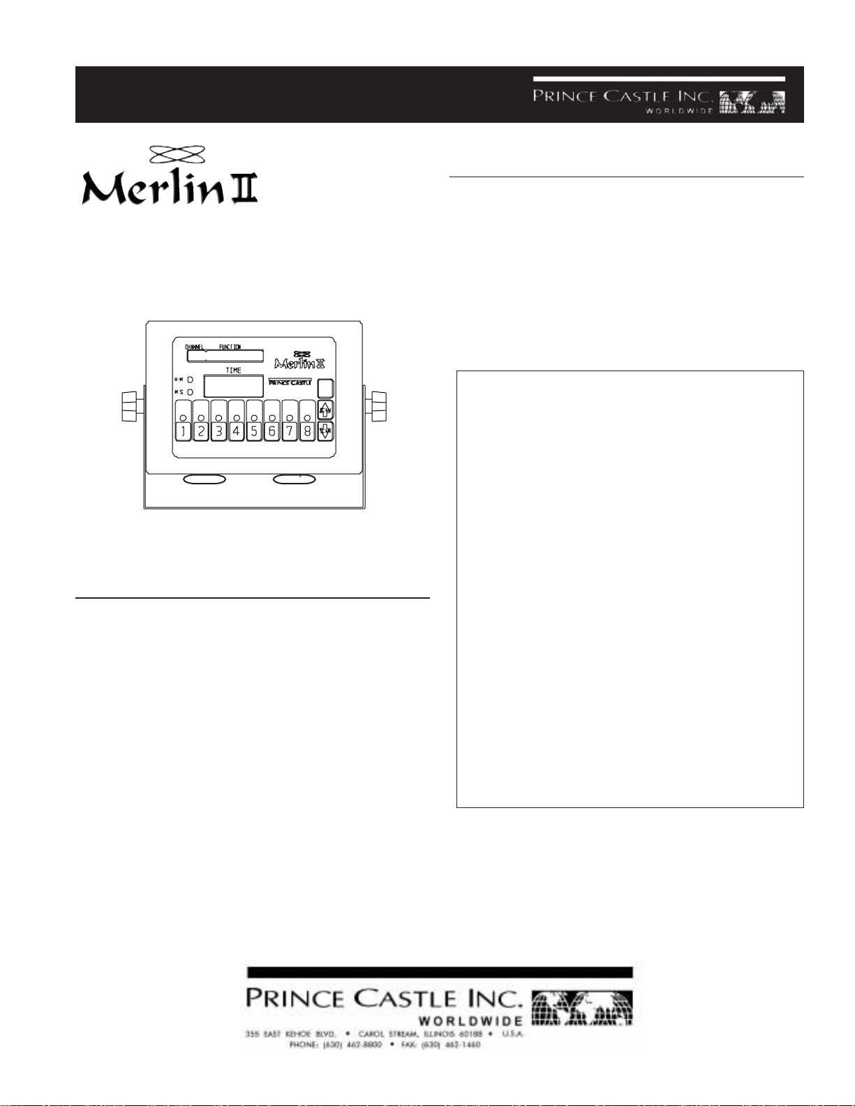
Pictured Model 840-C8
ELECTRICAL
840-C Series 840-CF Series
120 Volts 220 Volts
50/60 Hz 50/60 Hz
30 Watts
Single Phase
840-CJ Series
200 Volts
50/60 Hz
TABLE OF CONTENTS PAGE
Installation..................................................................... 2
Programming .............................................................. 2-7
Operation .................................................................... 7-8
Cleaning ........................................................................ 8
Parts List....................................................................... 8
Exploded View .............................................................. 9
Troubleshooting ............................................................ 9
Wiring Diagrams ......................................................... 10
840-509revA
Printed in USA 3/06 © 2006

Table Of Contents
I Introduction
III CONTROL PANEL
Function Display
Prince Castle
Button
II Installation
III Control Panel
IV Programming
A. Channel Programming.
B. Program Specials.
C. Probe A.
D. Probe B.
V Recovery Time Check
VI Operation
VII Cleaning
VIII Parts List Exploded View
IX Troubleshooting
X Wiring Diagram
I INTRODUCTION
The 840 Series Compensating Timers allow the user
great flexibility in programming options. Each channel
can be programmed to include a total cook time, three
duty functions during that cook time, a hold time and a
hold duty function. Each channel can be programmed to
use either Probe A or B for compensated time or no
probe at all for straight countdown time.
Time
Display
Time
Mode
Lights
Timer
Channel
Lights
ENTER
Timer Channel
Buttons
Enter
Button
Scan Up
&
Scan Down
Button
IV PROGRAMMING
There are four different programming features within the
program mode:
A) Program Timers is used to program the Cook,
Hold and Duty times for each channel.
B) Prog Probe A is used to program the set point
temperature or calibrate the left probe.
C) Prog Probe B is used to program the set point
temperature or calibrate the right probe.
D) Program Specials is used to select the
appropriate temperature scale (F or C), select
which probes will be used for each timer
channel or to test the fryer recovery time.
II INSTALLATION
1. After you have removed the timer from the carton,
inspect the unit for signs of damage. If there is
damage to the unit:
l Notify carrier within 24 hours after delivery.
l Save carton and packing materials for inspection
purposes.
l Contact your Prince Castle Dealer for replace-
ment or the Prince Castle Customer Sales
Department at 1-800-722-7853 if purchased
directly.
2. Verify that all parts have been received. Mounting
bracket and hardware are provided.
3. To mount the timer, place mounting brackets in desired location. Scribe location of mounting holes,
center punch, and drill holes. Attach timer to mounting brackets placing star washer between bracket and
timer.
Printed in USA 3/06 © 2006
1. Press and hold the PRINCE CASTLE LOGO for
eight seconds, a short beep will sound and LOGO
=QUIT will appear in the display.
LOGO=QUIT
- - - -
2
840-509revA
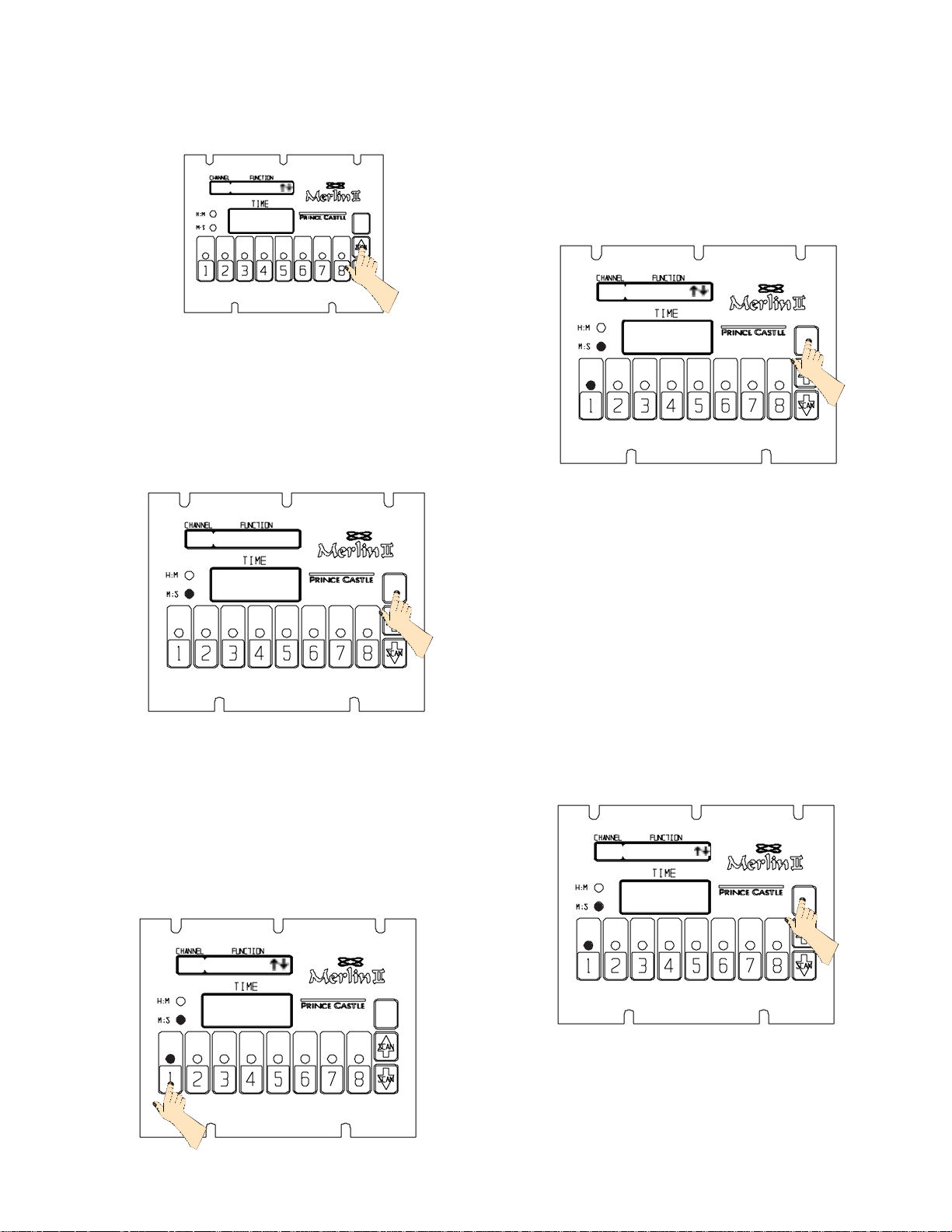
Press either the SCAN UP BUTTON or the SCAN
DOWN BUTTON to switch through the four pro-
gramming options until you get to the appropriate
option.
PROG SPECIAL
- - - -
3. At this point you can program in your complete
cook time by using the SCAN/UP BUTTON or the
SCAN/DOWN BUTTON. Once you have reached
your desired time press the ENTER button to store
your complete cook time.
IMPORTANT: To change from minutes and seconds M:S to hours and minutes H:M. press and
hold the SCAN/UP BUTTON. When the display
CKT=COOK TIME
Press the ENTER BUTTON to enter that program-
ming mode.
A. Prog. Timers
1. After pressing the ENTER BUTTON, SEL CH/
LOGO=QUIT will appear in the display.
SEL CH/LOGO = QUIT
ENTER
2. Press the TIMER CHANNEL BUTTON to be
programmed. The TIMER CHANNEL LIGHT will
turn Amber and a beep will sound. The FUNCTION
display will read, CKT=COOK TIME. The current
complete cook time for that channel will be displayed in the TIME display, and the TIME MODE
LIGHTS will indicate either H:M OR M:S.
6 : 0 0
ENTER
reaches 59:59 it will automatically change to 1:00
Hour and the TIME MODE LIGHT will switch from
M:S to H:M. The program value for the H:M indica-
tor is from 1:00 hour to 60 hours: 00 minutes.
4. Once you press ENTER , CKC=MAN CANCEL or
CKC=AUT CANCEL will appear in the FUNCTION
DISPLAY , press the SCAN UP BUTTON or SCAN
DOWN BUTTON to switch from one mode to the
other. Press the ENTER button to store your
selection or if no change is required.
CKC=MAN CANCEL
6 : 0 0
ENTER
840-509revA
CKT=COOK TIME
3 : 0 0
ENTER
3
Printed in USA 3/06 © 2006
 Loading...