

Prince Castle 837-C Service Manual
OPERATING
INSTRUCTIONS
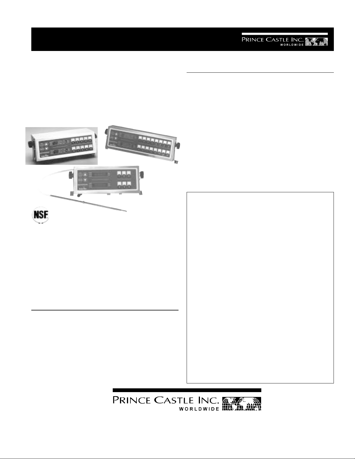
Multi-Function Timers
Model No. 836-C Single
Probe & 837-C Dual Probe
Series
Prince Castle’s 835-T Series Timers are designed so
each channel can be programmed independently,
and used simultaneously. The timers are simple to
program and simple to use. The push of a button
activates each channel, and an audible alarm and
flashing channel button alerts the operator when
timing is complete. Merlin timers operate on any
voltage worldwide and are backed by a two-year
warranty.
ELECTRICAL
836-C/837-C Series
100-240 Volts
50-60 Hz
4.5 Watts
Single Phase
TABLE OF CONTENTS PAGE
Installation..................................................................... 2
Terms and Functions ................................................... 2
Programming .............................................................. 2-4
Operating ....................................................................... 5
Data Tracking Counter ................................................. 6
Cleaning ........................................................................ 7
Installation of Menu Labels ......................................... 7
Translations (French, German, Spanish, Italian) ........ 8-31
Exploded View ............................................................ 32
Parts List..................................................................... 32
Trouble Shooting ........................................................ 33
Wiring Diagram ........................................................... 33
LIMITED WARRANTY
This product is warranted to be free from defects in
material and/or workmanship for a period of two
years from date of original installation, not to exceed 30 months from date of shipment from our
factory.
Any component which proves to be faulty in material
and/or workmanship will be replaced or repaired (at
the option of Prince Castle, Inc.) without cost to the
customer for parts or labor.
This warranty is subject to the following exceptions/
conditions:
! This equipment is portable, charges for on loca-
tion service (e.g. trip charges and mileage) are
not included in the provisions of this warranty.
! Use of any non-genuine Prince Castle parts
voids this warranty. All genuine Prince Castle
replacement spare parts are warranted for ninety
(90) days from date of purchase.
! Damage caused by carelessness, neglect, and/
or abuse (e.g., dropping, tampering or altering
parts), equipment damaged in shipment, by fire,
flood or an act of God is not covered under this
warranty.
Printed in March 1998
Prince Castle Inc.
355 East Kehoe Blvd. ! Carol Stream, IL 60188
Tel: (630) 462-8800
Toll Free: 1-800-PCASTLE
! Fax: (630) 462-1460
866-502
INSTALLATION
GLOSSARY OF TERMS
1. After you have removed the timer from the carton,
inspect the unit for signs of damage. If there is
damage to the unit:
! Notify carrier within 24 hours after delivery.
! Save carton and packing materials for inspection
purposes.
! Contact the Prince Castle Customer Sales
Department at 1-800-722-7853 to arrange for
a replacement to be sent.
2. Verify that all parts have been received.
CAUTION: Solid state components in this
timer are designed to operate reliably in
a temperature range up to 150° F (65.6°
C). When installing this timer it should
be confirmed that the ambient temperatures at the mounting site do not exceed
150°F (65.6° C).
3. Remove power cord, which is separate from the
unit, and plug one end into the power inlet located
on the unit. After mounting the unit, plug other end
into the receptacle.
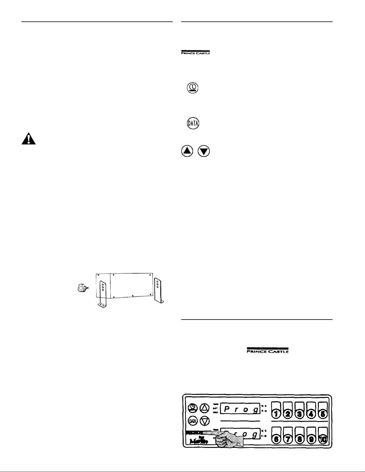
4. Locate mounting brackets in desired location.
Scribe location of mounting holes and center
punch. Remove timer from brackets. Drill holes
with a No. 29 (3.70 mm) drill bit and thread hole
with a #8-32 (m 4 X 0.7-6 G) tap. Mount timer with
(4) #8-32 screws provided. See figure 1.
figure 1
Timer
Duty
Hold
F I L t
OPEN
S H r t
Prince Castle Logo is pressed to put
the timer in program mode and to return
to run mode.
Clock Button allows you to set the timer
at minutes and seconds (M : S) or hours
and minutes ( H : M) while in the program
mode.
Data Button allows you to set the alarm
volume of the timer while in the program
mode. Also sets the data tracking
system in the run mode.
Up and Down Arrows allow you to
increase or decrease time or alarm
volume while in program mode.
Timer, is the operation time set in the
computer.
Duty Time allows a selected function to
be performed at a set time during the
cooking process and/or the holding
process.
The Hold Function allows you to hold
cooked product for a selected time before
discarding.
A built in Filter Reminder Option lets
you know when to filter.
Open Probe.
Shorted Probe.
IMPORTANT: This unit can be mounted to a variety of
surfaces. Additional hardware may be required.
This timer has been designed with worldwide voltage. It
can be plugged into any voltage range between 100 V
and 240 V, 50-60 Hz, single phase outlet.
IMPORTANT: This should be plugged into a dedicated
outlet. No other equipment should be operating on this
line (i.e. fryers, refrigerators, cash registers, etc.)
IMPORTANT: Customers outside the USA, Canada,
Great Britain, and non-CE (Continental Europe) countries must cut off the three prong plug on the end of the
power cord or use an adapter (not included).
H I
L O
Probe is sensing a High Temperature.
Probe is sensing a Lo Temperature.
PROGRAMMING
1. Press and hold the for five seconds until “Prog” appears in the displays and the
timer beeps. You are now in the Program mode.
See figure 2.
figure 2
2
IMPORTANT: If a channel is not pressed within 30
seconds the display will change to “--:--” and the timer
will automatically go back into the run mode.
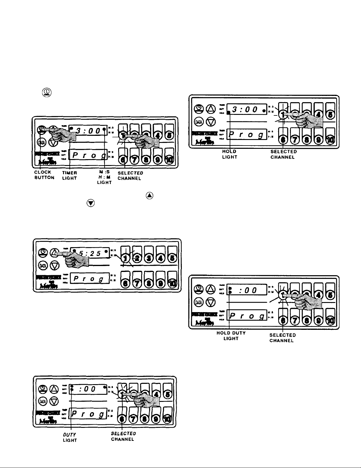
2. To set an operation time on a particular channel
press the number for the channel. The channel will
then light up and flash, and TIMER light will come
on. The display will show the current complete
programmed time that channel. The light by M:S
will also be lit. To switch time to H : M press the
See figure 3.
figure 3
3. To change, or set, the time press the arrow to
increase, or the arrow to decrease. The timer
can be set up to 99 minutes and 59 seconds or 99
hours and 59 minutes. See figure 4.
figure 4
IMPORTANT: The duty time must be set in the same
time mode as the operation time.
5. Press the selected channel number again. The
current hold time will be displayed and a there will
be a light by Hold. The hold time can be set in M :
S or H : M. To set a hold time repeat step 3.
See figure 6.
figure 6
6. After the Hold time has been set, press selected
channel number once again. The light by Duty will
be lit. This feature allows a duty time to be set
while a product is being held. For example, a Duty
time can be set to remind the operator to make
another run of a product. If no Duty is needed the
time can be set to : 00. Press the selected number again. The display will show “Prog”. This
means programming is completed. Repeat steps
2-6 for all other channels. See figure 7.
IMPORTANT: Pressing and holding the arrow will
make the numbers move at a faster pace.
4. Once operation time is programmed press the
selected channel. The display will show the
current duty time and there will be a light by Duty.
To set a duty time repeat step 3. If no duty time is
needed set to :00. See figure 5.
figure 5
figure 7
IMPORTANT: The duty time must be set in the
same time mode as the hold time.
3
 Loading...