

Page 1
OPERATING
740-520revA
Printed in USA 3/06 © 2006
INSTRUCTIONS
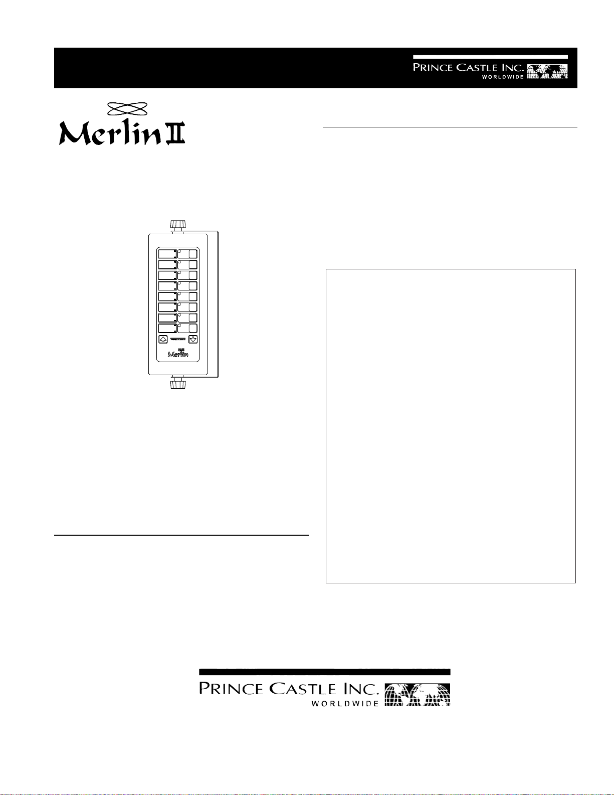
Slow Cook/Hold Timers
Model No. 740-TCE &
740-TGB Series
Pictured Model 740-T88
Model Description
740-T44 Four Channel
740-T66 Six Channel
740-T88 Eight Channel
ELECTRICAL
TABLE OF CONTENTS
Installation..................................................................... 2
Programming................................................................. 2
Operation ....................................................................... 3
Cleaning ........................................................................ 4
Parts List....................................................................... 4
Exploded View .............................................................. 5
Troubleshooting ............................................................ 5
Wiring Diagrams ........................................................... 6
LIMITED WARRANTY
This product is warranted to be free from defects in material
and/or workmanship for a period of 1 year from date of original
installation, not to exceed 18 months from the date of
manufacture.
Any component which proves to be faulty in material and/or
workmanship will be replaced or repaired (at the option of
Prince Castle, Inc.) without cost to the customer for parts and
labor. This equipment is portable; charges for on-location
service (e.g., trip charges, mileage) are not included in the
provisions of this warranty.
This warranty is subject to the following exceptions/conditions:
• Use of any non-genuine Prince Castle parts voids this
warranty.
• All labor to be performed during regular work hours.
Overtime premium (the incremental amount) will be charged
to the customer.
• Damage caused by carelessness, neglect and/or abuse
(e.g., dropping, tampering or altering parts, equipment
damaged in shipment, by fire, flood or an act of God) is not
covered under this warranty.
• All problems due to operation at voltages other than that
specified on equipment nameplates are not covered by this
warranty. Conversion to correct voltage is the customer’s
responsibility.
• This equipment must be serviced by Prince Castle
Authorized Service Agency or a Prince Castle Service
Technician during the warranty period.
PAGE
740-TCE & TGB Series
230 Volts
10 Watts
50-60 Hz
355 East Kehoe Blvd. z Carol Stream, IL 60188
Tel: (630) 462-8800 z Fax: (630) 462-1460
Toll Free: 1-800-PCASTLE
Page 2
INSTALLATION
Printed in USA 3/06 © 2006
740-520revA
1. After you have removed the timer from the carton,
inspect the unit for signs of damage. If there is
damage to the unit:
z Notify carrier within 24 hours after delivery.
z Save carton and packing materials for inspection
purposes.
z Contact your local Prince Castle dealer to
arrange for a repair or a replacement to be sent.
2. Verify that all parts have been received. Mounting
Brackets and hardware provided.
3. To mount the timer, place mounting brackets in desired location. Scribe location of mounting holes,
center punch, and drill holes. Attach timer to mounting brackets placing star washer between bracket and
timer.
DISPLAYS AND INDICATORS
PRINCE
adjust the alarm sound level.
CASTLE
Logo
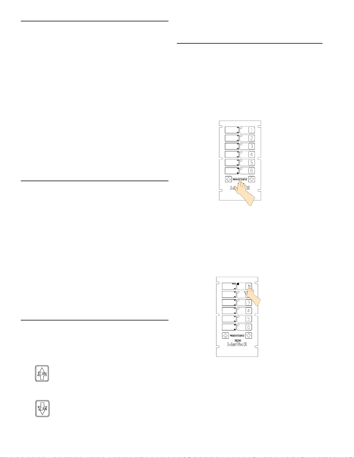
PROGRAMMING
1. Press and hold the PRINCE CASTLE logo for six
seconds. The TIME displays change will from ---to Prog and a beep will sound.
See figure 1.
Figure 1
Prog
Prog
Prog
Prog
Prog
Prog
Shows the time for the selected channel
TIME
number.
Display
Indicates the time value is in Hours and
H:M
Minutes.
Indicates that the time value is in
M:S
Minutes and Seconds.
Located above each channel timer
LED
Indicators
button, these lights change color
depending on the stage of the countdown. Green = first 70% of countdown,
Yellow = next 20% countdown,
Red = last 10% of countdown.
CONTROLS
Activates countdown sequence in the
Channel
(Button)
SCAN/UP
ARROW
SCAN/DOWN
ARROW
run mode.
In the program mode, it increases time
values for each channel . In the Run
Mode, it is used in conjunction with logo
button to increase the volume.
In the program mode, it decreases time
values for each channel . In the run
mode, it is used in conjunction with logo
button to decrease the volume.
Activates Program Mode and used to
2. Press the timer channel to be programmed. The
LED indicator for the selected button will turn
yellow and a beep will sound. The current programmed time for that channel will be displayed in
the TIME display and the time value will indicate
either H:M OR M:S. See figure 2.
Figure 2
3:00
3. Press the SCAN/UP Arrow or the SCAN/DOWN
Arrow button to change the program time for the
selected channel.
2
Page 3

IMPORTANT: To change from Minutes and Seconds
740-520revA
Printed in USA 3/06 © 2006
M:S to Hours and Minutes H:M. Press and hold the
SCAN/UP Button. When the display reaches 59:59 it
will automatically change to 1:00 Hour and the LED will
switch from M:S to H:M. The program value for the
H:M indicator is from 1:00 hour to 17 hours: 59 minutes. See figures 3 and 4.
Figure 3
59:59
Figure 4
Figure 5
6. You can change the sound level of the alarm in
RUN MODE. Press and hold the PRINCE CASTLE
logo; then, within six seconds, press either the
SCAN UP Arrow button or the SCAN DOWN Arrow
button. The SCAN UP Arrow button adjusts the
sound level to the louder alarm, the SCAN DOWN
Arrow button adjusts the sound level to the lower
alarm.
1:00
4. Press the desired channel button to program
another channel. Repeat programming procedures
in steps 2 and 3 above.
5. When finished programming each desired channel,
momentarily press the PRINCE CASTLE logo to
end the Program Mode. This saves the program
changes you have made for all channels.
See figure 5.
OPERATION
1. Press a channel button to activate a timing cycle.
(All channels can be activated and running at the
same time.) The time remaining will countdown in
the TIME display, and the time value M:S or H:M will
be illuminated. See figure 6
Figure 6
2:59
2. Press the desired channel button three times within
five seconds to cancel an active timing cycle.
3
Page 4

IMPORTANT: The channel timer button’s multicolored
Printed in USA 3/06 © 2006
740-520revA
LED indicator shows the status of the timer. The
indicator has three colors: green, yellow, and red. The
LED will be green during the first 70% of the countdown. It changes to yellow during the next 20% of the
countdown. It will be red during the final 10% of the
countdown, and will start flashing red once the time
has run out.
3. The timer will countdown from the programmed
value to zero. At zero, the display flashes End and
the alarm sounds. See figure 7.
PART LIST
ITEM PART NUMBER DESCRIPTION
1 69-079S Plastic Rivet (Pkg. Of 2)
2 740-030 Rear Cover (T88)
740-034 Rear Cover (T44 & T66)
3 740-067S Main P.C. Board (T44)
740-065S Main P.C. Board (T66 & T88)
Figure 7
End
4. When the timing cycle is complete, and the alarm
sounds, press the channel button to cancel the
alarm. See figure 7.
4 740-077S Wing Board (T88 Only)
5 88-653-2-4S Speaker Assy.
6 541-135 Speaker Shim
7 740-026S Switch Panel Assy. (T88)
740-027S Switch Panel Assy. (T66)
740-028S Switch Panel Assy. (T44)
740-089S Switch Panel Assy. (T66MC)
8 740-032 Front Cover (T88)
740-036 Front Cover (T66 & T44)
9 70-048S Knob W/Hardware
10 72-293-05CES Power Supply
72-293-07GBS Power Supply
CLEANING
1. Do not allow grease to build up on the timer, wipe it
down daily with clean damp cloth.
IMPORTANT: Do not use abrasive or chemical cleaners
on your timer, this may cause damage to the overlay.
4
Page 5

EXPLODED VIEW
740-520revA
Printed in USA 3/06 © 2006
8
9
7
4
2
3
5
6
10
1
TROUBLESHOOTING GUIDE
PROBLEM
A. No displays or indicators lit. Unit unplugged. Plug unit in.
Store's circuit breaker blown. Reset breaker.
Defective transformer. Replace Main Circuit Board.
Circuit inoperable. Replace Main Circuit Board.
B. Absence of Audio Alarm. Speaker inoperable. Replace Speaker.
Circuit inoperable. Replace Main Circuit Board.
C. Unit will not enter program All channels are still counting. Wait until channels are in stop
mode. Display does mode.
not show "Prog". Logo Switch inoperable. Replace Switch Panel.
D. Unit enters program mode. The channel is still counting. Wait until channel is in stop mode.
Display shows "Prog", but Arrow Switch inoperable. Replace Switch Panel.
cannot change times. Circuit inoperable. Replace Main Circuit Board.
CAUSE
SOLUTION
E. Unable to start, stop, or store Circuit inoperable. Replace Switch Panel. If
timer presets in program mode. problem persists, replace Main
Missing or abnormal characters Circuit Board.
in displays.
5
Page 6

WIRING DIAGRAM 740-T44,T66 &T88
Printed in USA 3/06 © 2006
740-520revA
6
 Loading...