

Page 1
GAS SERIES
OUTDOOR GAS GRILL
INSTALLATION INSTRUCTIONS
AND OWNER’S MANUAL
MODEL# G420C (Freestanding) G420H (Head only)
INSTALLER: Leave these instructions with the consumer.
CONSUMER: Retain for future reference
IMPORTANT: READ THESE INSTRUCTIONS CAREFULLY BEFORE STARTING INSTALLATION OR USE.
WARNINGS AND SAFETY CODES
DANGER:
IF YOU SMELL GAS:
1. Shut off the gas to the appliance.
2. Extinguish any open ame.
3. Open lid.
4. If odor continues, keep away from the
appliance and immediately call your gas
supplier or the re department.
CODE AND SUPPLY REQUIREMENTS: This
grill must be installed in accordance with local
codes and ordinances, or, in the absence of local
codes, with the latest National Fuel Gas Code
(ANSI Z223.1/NFPA 54), or Natural Gas and
Propane Storage and Handling Installation Code
(CSA-B149.1).
This appliance and its dedicated manual shutoff
valve must be disconnected from the gas-
supply piping system when testing the system at
pressures in excess of 1⁄2 psig (3.5 kPa).
This appliance must be isolated from the gassupply piping system by closing its dedicated
manual shutoff valve during any pressure testing
of the gas-supply system at pressures up to and
including 1⁄2 psig (3.5 kPa).
Proper operation of your grill requires prompt
and periodic maintenance. See the CARE &
CLEANING section for details.
Keep all electrical-supply cords and fuel-supply
hoses away from any heated surface.
WARNING
WARNING:
Improper installation, adjustment, alteration,
service, or maintenance can cause injury or
property damage. For proper installation, refer
to the installation instructions. For assistance
or additional information, consult a quali ed
professional service technician, service agency,
or the gas supplier.
WARNING:
1. Do not store or use gasoline or other
ammable vapors and liquids in the vicinity
of this or any other appliance.
2. An LP cylinder not connected for use shall
not be stored in the vicinity of this or any
other appliance.
PCG.rev04282017- 10:53
Page 2

PCG.rev04282017- 10:53
Page 3
INSTALLATION INSTRUCTIONS ET MANUEL DU PROPRIÉTAIRE
PRIMO GRIL EXTÉRIEUR DE GAZ DU PORTATIF
IMPORTANT: LISEZ CES INSTRUCTIONS SOIGNEUSEMENT AVANT DE COMMENCER OU L’INSTALLATION L’UTILISATION
INSTALLATEUR : Laissez ces instructions avec le consommateur.
CONSOMMATEUR : Maintenez pour la future référence.
SÛRETÉ ET CODES D’AVERTISSEMENT
DANGER:
SI VOUS SENTEZ LE GAZ :
1. Coupezl’admissiondegazdeI’appariel.
2. Éteindre toute amme nue.
3. Ouvrir le couvercle.
4. Si l’odeur persiste, éloignez-vous de
l’appareil et appelez immédiatement le
fournisseur de gaz ou le service d’incendie.
CONDITIONS DE CODE ET D’APPROVISIONNEMENT:
Ce gril doit être installé selon des codes et des ordonnances
locaux, ou, en l’absence des codes locaux, avec l’un ou
l’autre le plus défunt Code national de gaz de carburant
(norme ANSI Z223.1/NFPA 54), et Stockage de gaz naturel
et de propane et manipulation du code d’installation
(CSA-B149.1).
Cet appareil et ses différents robinets d’isolement doivent être
démontés du gaz-fournissent le système sifant en examinant
le système aux pressions au-dessus du 1⁄2 psig (kPa 3.5).
Cet appareil doit être isolé dans gaz-fournissent le système
sifant par fermeture que ses différents robinets d’isolement
manuels pendant tous les essais sous pression du gazfournissent le système aux pressions jusques et y compris le
1⁄2 psig (kPa 3.5).
• Ce gril est pour ultilisation à l’extérieur seulement. Si
l’appareil est entreposé à l’intérieur, enlever les bouteilles
et les laisser à l’extérieur.
• Ne pas ranger le gril immédiatement aprés l’avoir utilisé.
le laisser refroidir avant de le déplacer ou de la ranger.
Le non respect de cette mesure de sécurité pourrait
entraîner un incendie causant des dommages à la
propriété, des blessures ou la mort.
• Ne pas utiliser cet appareil sous une surface combustible.
• Ne pas utiliser cet appareil sous un auvent. Le non
respect de cette mesure de sécurité pourrait entraîner un
incendie ou des blessures.
• Dégagement minimal entre les parois latérales et l’arriére
de l’appareil et la construction combustible (45.7 cm à
partir des parois latérales et 45.7cm à partir de l’arriére).
• Le régulareur de pression de gaz prévu avec cet appareil
de cuisson à gaz pour l’extérieur doit être utilisé. Ce
régulateur est réglé pour une pression de sortie de 5
pouces de colonne de l’eau pour le gaz naturel, et 10
pouces pour le propane.
• LE RÉGULATEUR INCLUS D’APPAREILS EST ÉVALUÉ
POUR LE MAXIMUM DE 1/2 (LIVRES PAR POUCE
CARRÉ). SI VOTRE OFFRE DE GAZ EST 1/2 PLUS
GRAND QUE (LIVRES PAR POUCE CARRÉ), UN
RÉGULATEUR ADDITIONNEL DOIT ÊTRE INSTALLÉ
Maintenez tout électrique-fournissent des cordes et
carburant- fournissent des tuyaux partis de n’importe quelle
surface de chauffage.
AVANT LE GRIL. VOIR LA SECTION DE CONDITIONS
D’OFFRE DE GAZ POUR LA PRESSION APPROPRIÉE
D’OFFRE DE GAZ.
• Ne couvrez jamais la surface entière de cuisine ou de
gril de gauffreuses ou de casseroles. La surchauffe se
produira et les brûleurs ne seront pas très performants
quand la chaleur de combustion est emprisonnée au-
dessous de la surface à cuire.
• Ne pulvérisez jamais l’eau sur une unité chaude de gaz,
comme ceci peut endommager des composants de
porcelaine ou de fer de fonte.
• Une fuite de GPL peut causer une incendie ou une
explosion si enammée entraînant des blessures
corporelles graves ou la mort.
• Communiquez avec le fournisseur de GPL pour les
réparations ou pour disposer de qules bouteille ou du
GPL non utilisé.
AVERTISSEMENT
AVERTISSEMENT:
L’installation inexacte, l’ajustement, le
changement, le service, ou l’entretien peuvent
causer des dommages ou des dégats matériels.
Référez-vous à ce manuel. Pour de l’aide
ou des renseignements supplémentaires,
consultez un technicien professionnel qualié
de service, une agence de service ou le
fournisseur de gaz.
AVERTISSEMENT:
1. Ne stockez pas ou n’employez pas l’essence
ou d’autres vapeurs et liquides inammables
à proximité de ceci ou d’aucun autre
appareil.
2. Un cylindre de propane non relié pour
l’usage ne sera pas stocké à proximité de
ceci ou d’aucun autre appareil.
PCG.rev04282017- 10:53
Page 4

TABLE OF CONTENTS
Getting Started
MODEL SPECIFICATIONS ........................................................................................................ 1
HEAD UNIT ONLY CUTOUT SPECIFICATIONS ....................................................................... 2
ENCLOSURE REQUIREMENTS ............................................................................................... 3
REPLACEMENT PARTS ............................................................................................................ 4
GRILL MAINTENANCE & SAFETY ............................................................................................ 5
INSTALLATION REQUIREMENTS ............................................................................................6
PROPANE SAFETY INFORMATION ......................................................................................... 9
SAFE USE AND MAINTENANCE OF PROPANE GAS CYLINDERS ...................................... 10
Installation
INSTALLATION ........................................................................................................................12
LOCATION PREPARATION ..................................................................................................... 12
WHEELS AND CASTERS ........................................................................................................ 12
CONNECT THE GAS SUPPLY ................................................................................................ 12
INSTALL THE IGNITER BATTERY ..........................................................................................13
USING THE FOLDING SHELVES ............................................................................................ 13
BURNER SPECIFICATIONS AND INSTALLATION ORIENTATION ....................................... 17
Use, Care & Maintenance
IDENTIFICATION OF GRILL CONTROLS ............................................................................... 13
LIGHTING/IGNITION INSTRUCTIONS ....................................................................................14
CONVERT GAS TYPE & CHECK BURNER ORIFICES .......................................................... 16
CONTROL PANEL REMOVAL ................................................................................................. 18
TROUBLESHOOTING .............................................................................................................19
CARE & CLEANING .................................................................................................................20
WARRANTY .............................................................................................................................21
PCG.rev04282017- 10:53
Page 5
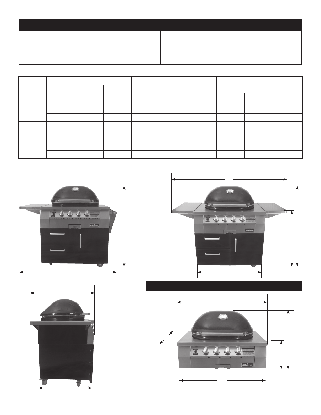
MODEL SPECIFICATIONS
Main (High Burner)
N/P ori ce drill size
Seconadary (Low Burner)
N/P ori ce drill size
LP #66 / NAT #56
LP #76 / NAT #70
NOTE:
G420C (Freestanding) ships with
propane ori ce installed. G420H
(Head only) ships with natural gas
ori ce installed.
DIMENSIONS
Model Height Width Depth
G420C
G420H
Floor to Top of Grill
Open
(A)
60" 46" 34" 36" 60-1/2" 53-1/2" 26" 29"
Base of shroud to
Top of Grill
Open
(A)
37" 23" 11" 36-1/4" 29"
Closed
(B)
Closed
(B)
Floor to
top of
shelf
(C)
Shroud
height
(C)
Cart Base
(D)
With shelves Front to back
Up
(E)
Shroud Width
(E)
1 up &
1 down
(F)
Cart Base
(G)
Maximum outer
Maximum outer
** 5" from back of unit wall clearance required to open lid **
E
(H)
(H)
B
F
G420H HEAD UNIT ONLY
H
D
B
C
E
B
H
C
D
G
1
PCG.rev04282017- 10:53
Page 6
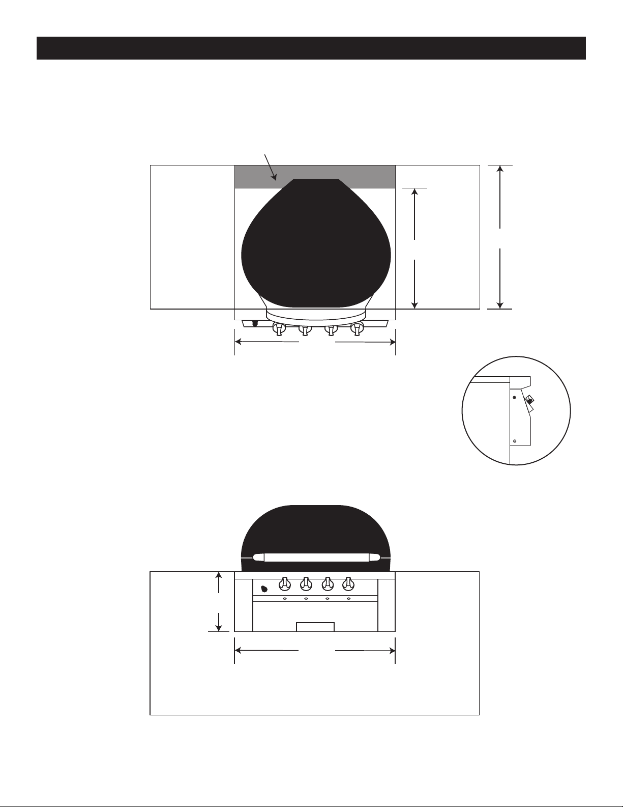
G420H HEAD UNIT ONLY CUTOUT AND INSTALLATION
4-1/4” of open space behind grill
23-1/4”
27-1/2”
36 1/2”
Top View
NOTE: 4-1/4” open space behind grill shroud is required for hinge clearance.
NOTE: 10" of clearance from back of hinge required to open lid.
4-1/4” of open space behind grill
NOTE: The control panel is designed to protrude past the front of the
countertop surface. (g. 1)
IMPORTANT: The G420H is a slide-in installation, not a hanging
installation. The base of the metal grill surround must be supported from the
bottom edges.
23-1/4”
27-1/2”
36 1/2”
g. 1
Front View
11”
36 1/2”
* Note: If installing this grill in a combustible enclosure, the correct insulating liner must be used.
Consult liner instructions for counter cut-out dimensions and installation.
PCG.rev04282017- 10:53
2
Page 7
ENCLOSURE REQUIREMENTS
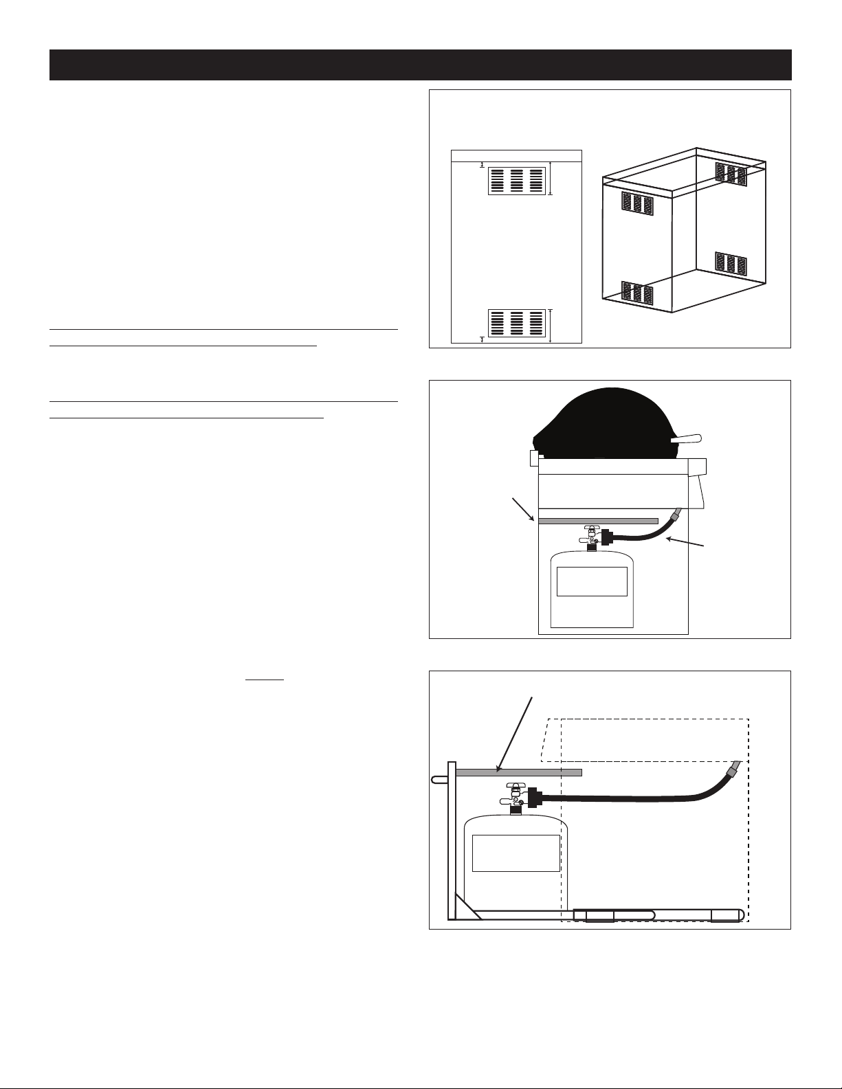
Ventilation Requirements
VENTILATION (ALL ENCLOSURES)
For All Piping Systems and All Gas Types: (Natural
Gas, Household Propane, L.P. Cylinder)
FOR YOUR SAFETY, you must provide the openings
listed below for replacement air and cross-ventilation
of the unit enclosure.
One side of the enclosure shall be left completely
open to the outside; OR 4 (minimum) ventilation
openings MUST be created (reference Fig. 1):
Each opening must have a minimum of 10 sq. in. of
free area. The openings must be equally sized and
unobstructed.
Two openings must be in the side walls of the enclosure,
at the top level, and spaced at 180 degrees. The openings
must begin 1" or less below the countertop level and end
no more than 5" below the countertop level.
Two openings must be in the side walls of the enclosure,
at the oor level, and spaced at 180 degrees.The openings
must begin 1" or less above the oor level and end no
more than 5" above the oor level.
To achieve the proper ventilation, you may use venting
panels as shown. Contact your dealer.
KEEP THE VENT OPENINGS AND SURROUNDING
AREA OF THE ENCLOSURE CLEAN AND FREE OF
OBSTRUCTIONS AT ALL TIMES.
WARNING: Ventilation openings in side walls shall not
communicate directly with other enclosures of the outdoor
cooking gas appliance.
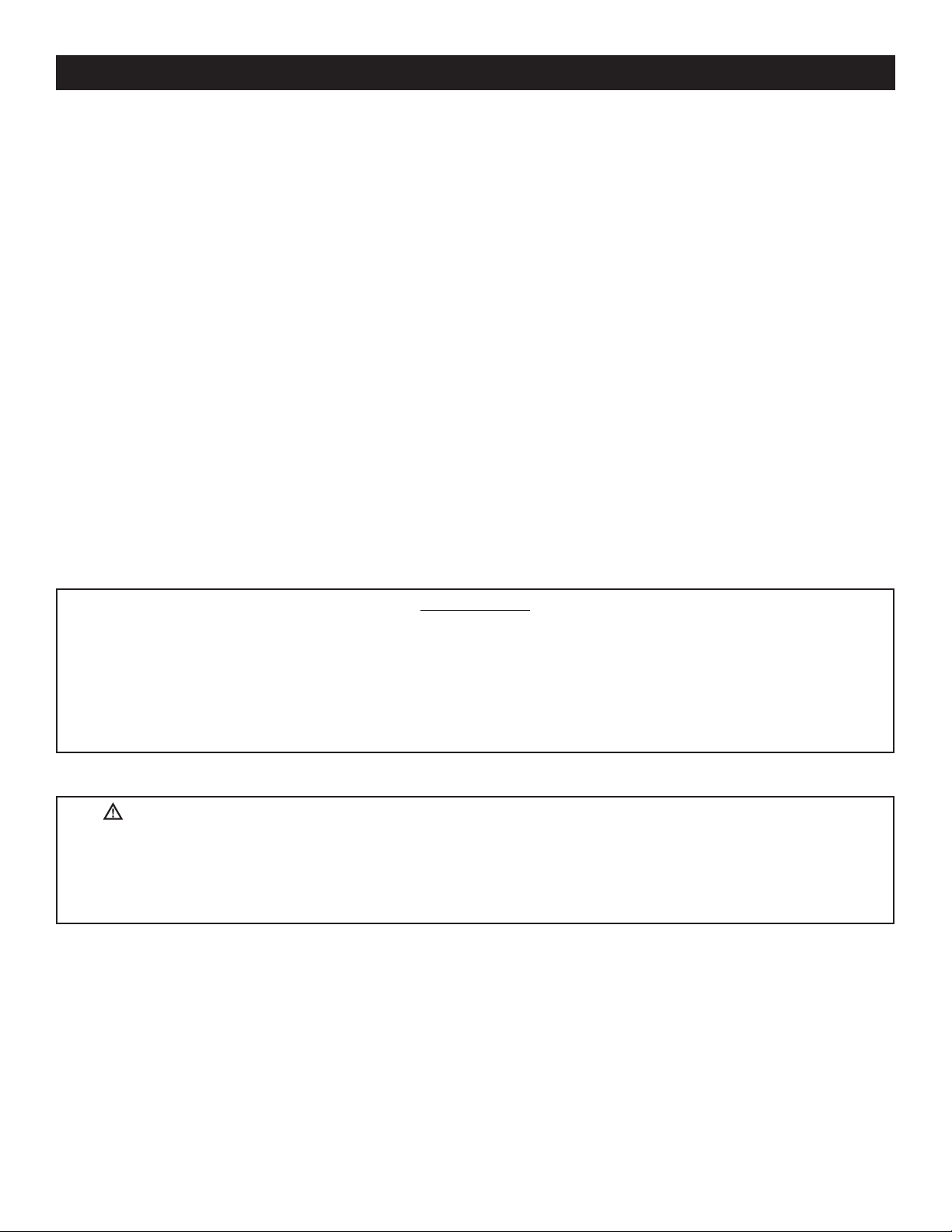
WHEN A PROPANE (L.P.) CYLINDER IS USED IN THE
ENCLOSURE
When a propane (L.P.) cylinder is installed inside of the
enclosure, the guidelines below MUST be followed.
FAILURE TO DO SO MAY CAUSE DAMAGE TO YOUR
UNIT AND/OR PERSONAL INJURY. Reference Fig. 2 for
an example.
• A non-combustible heatshield must be installed to
protect the regulator/hose assembly and propane
cylinder valve.
• Many dealers offer propane tank door with tank tray
models and a propane tank heatshield that rests
directly on the tank to meet the cylinder install
requirements. Propane tank door with tank tray
shown in Fig. 3. Contact your dealer for ordering
information.
• 4 openings minium with 2 per side wall, spaced at 180º.
• Top openings within 5” of countertop
• Bottom openings withing 5” of floor.
1” min
4 total vent openings at
10 sq. in. of free area
minimum each
1” min
5” max
Surrounding area and vent openings
5” max
must be clear for proper venting.
Fig. 1 Ventilation detail
Non-combustible
heat shield
L.P. Cylinder
Fig. 2 Propane cyilnder orientaion
Cylinder and regulator/hose assembly
protected by heat shield
L.P. Cylinder
Regulator/hose
assembly
Fig. 3 Optional door with propane tank tray
3
PCG.rev04282017- 10:53
Page 8

REPLACEMENT PARTS
PART NUMBER PART DESCRIPTION QTY HEAD CART
0142001 CERAMIC BOTTOM 1 • •
0142002 CERAMIC TOP 1 • •
0142003 INTERNAL STAINLESS STEEL BASKET 1 • •
0142004 STAINLESS STEEL FLAVOR GRATE 2 • •
0142005 STAINLESS STEEL COOKING GRATES 2 • •
0142006 STAINLESS STEEL HANDLE 1 • •
0142007 CONVERTER KIT FOR ORIFICES 1 • •
0142008 METAL FRAME WITH DOORS 1 •
0142009 UPPER METAL FRAME 1 • •
0142010 STAINLESS STEEL FRONT PANNEL 1 • •
0142011 INSIDE STAINLESS STEEL SIDE TABLES 2 • •
0142012 STAINLESS STEEL DRIP PAN TRAY 1 • •
0142013 STAINLESS STEEL FOLD DOWN SIDE TABLES 2 •
0142014 STAINLESS STEEL HINGE MECHANISM 1 • •
0142015 KNOBS FOR GAS VALVE 4 • •
0142016 NAME PLATE 1 • •
0142017 GAS VALVES 4 • •
0142018 ELECTRONIC IGNITOR KNOB 1 • •
0142019 CERAMIC ELECTRODES 2 • •
0142020 GAS PILOT TUNNEL BOX 2 • •
0142021 HOSE FOR NATURAL GAS WITH QUICK DISC 1 •
0142022 GAS MANIFOLD 1 • •
0142023 PROPANE HOSE WITH REGULATOR 1 •
0142024 SHORT STEEM THERMOMETER WITH SLEEVE 1 • •
0142030 MANUAL 1 • •
0142032 LOW HEAT BURNERS 2 • •
0142033 HIGH HEAT BURNERS 2 • •
0142034 V-SHAPED SMOKER BOX 1 • •
PCG.rev04282017- 10:53
4
Page 9
GRILL MAINTENANCE & SAFETY
1. The outdoor grill and surrounding area MUST
remain clear of ammable substances such
as gasoline, yard debris, wood, etc.
2. The airow through the vent space located
below the control panel must remain
unobstructed.
3. When using propane gas:
a. The required ventilation openings in the
enclosure must be clear of debris. See the
PROPANE SAFETY INFORMATION section.
b. The propane cylinder, regulator, and rubber
hose must be in a location not subject to
temperature above 125° F (51° C).
4. The ames on each burner burn evenly along
the entire burner with a steady ame (mostly
blue). If burner ames are not normal, check
and clean the orice and burner/venturi tubes
for insects and insect nests. A clogged tube
can lead to a re beneath the grill. A proper
ame pattern will ensure safe operation and
optimal performance.
5. The in-line gas valve or gas cylinder valve
must always be shut OFF when the grill is not
in use.
6. The drip collector holes must be clear and
unobstructed. Excessive grease deposits can
result in a grease re.
7. Whenever reconnecting any wires, apply a
small amount of dielectric grease to the male
connector, then make the connection. This
will ensure conductivity and prevent moisture
from affecting the contact.
IMPORTANT
IN THE EVENT OF A GREASE FIRE, IMMEDIATELY SHUT OFF THE MAIN GAS VALVE TO THE
UNIT. KEEP THE LID OPEN AND ALLOW THE FIRE TO EXTINGUISH ITSELF. A THOROUGH
INSPECTION BY A TRAINED SERVICE TECHNICIAN SHOULD BE CONDUCTED BEFORE
FUTURE USE OF YOUR UNIT. THE SERVICE TECHNICIAN WILL CHECK THE SYSTEM FOR
GAS LEAKS AND WILL CHECK ALL ELECTRICAL WIRING FOR DAMAGE. ALL GAS LEAKS
AND WIRING MUST BE REPAIRED PRIOR TO FUTURE USE.
WARNING: NEVER cover the entire cooking or grill surface with griddles or pans.
Overheating will occur, and burners will not perform properly when combustion heat is
trapped below the cooking surface.
CAUTION: NEVER spray water on a hot gas unit.
5
PCG.rev04282017- 10:53
Page 10

INSTALLATION REQUIREMENTS
Non-Combustible Wall
Installation must be performed by a qualied
professional service technician.
This grill is designed for outdoor use only. DO
NOT use this grill inside a building, garage, or
enclosed area. DO NOT use this grill in or on a
recreational vehicle or boat.
When installing this grill in a combustible
surround, an insulating liner must be used.
The grill must have a minimum clearance of 18”
from combustible materials/items in all directions.
OVERHEAD CONSTRUCTION AND EXHAUST
HOOD REQUIREMENTS
A minimum of 5 foot clearance is required
between the counter top and the overhead
construction.
When installed under combustible overhead
construction, the area above the cooking surface
of the grill must be covered with an exhaust
hood. The exhaust hood provides the protection
for the combustible overhead construction. See
exhaust hood information below and Figure A.
*Combustible overhead construction:
Exhaust hood required
Non-combustible overhead construction:
Exhaust hood highly recommended
**Overhead Construction**
Exhaust Hood
5’ Minimum
Figure A. Overhead construction requirements.
Important: DO NOT use this appliance under
unprotected combustible overhead construction.
When installed under overhead non-combustible
construction, an exhaust hood is highly
recommended; see exhaust hood information
below and Figure A.
Exhaust Hood
When using an exhaust hood, the area above the
cooking surface of the grill must be covered with
a hood larger than the cooking area of the grill,
and with a minimum of 1200 CFM (cubic feet per
minute) for proper outdoor application.
PCG.rev04282017- 10:53
6
Page 11

INSTALLATION REQUIREMENTS
Non-Combustible Wall
Non-Combustible 4”
Combustible
Non-Combustible Substrate
Combustible
SIDE AND REAR WALL CLEARANCES
NOTE:
10" from back of hinge required to open lid.
For the minimum clearances between the grill
and any side or rear walls, your setup must fall
within one (or more) of the following:
A. Clearance between grill and strictly non-
combustible wall
(i.e. brick wall, see Figure 1)
• The grill must have a minimum of 4" right, left,
and rear clearance from any non-combustible
wall.
(To allow for proper ventilation and prevent
dangerous overheating.)
B. Clearance between grill and a protected
combustible wall
4”
Figure 1 Clearance ‘A’ Diagram
(i.e. a non-combustible wall in front of a
combustible wall to serve as a barrier. This
can be accomplished by brick, or a metal stud
nished with non-combustible substrate, see
Figure 2)
• The grill must have a minimum of 14" right,
left, and rear clearance from the protected
combustible wall.
(The 4" non-combustible material plus an
additional X" clearance between the grill and
protected wall.)
C. Clearance between grill and combustible
wall
• The grill must have a minimum of 18" right, left,
and rear clearance from any combustible wall
(see Figure 3).
BACKSPLASH CLEARANCE (IF APPLICABLE)
If a non-combustible backsplash exists, it must
have a minimum of a 5” clearance from the
rear of the grill (to allow for hinge clearance,
proper ventilation and to prevent dangerous
overheating). See Fig. 4.
14”
Figure 2 Clearance ‘B’ Diagram
18”
Figure 3 Clearance ‘C’ Diagram
4-1/4” of open space behind grill
23-1/4”
36 1/2”
27-1/2”
Figure 4 Backsplash Clearance Diagram
7
PCG.rev04282017- 10:53
Page 12

INSTALLATION REQUIREMENTS
The control panel MUST remain removable for servicing (see PARTS LIST).
ENSURE PROPER COMBUSTION AIR AND COOLING AIRFLOW
Proper airow MUST be maintained for the grill to perform as it was designed. If airow is blocked,
overheating and poor combustion will result. Do not block air inlet along the bottom of the control
panel or more than 75% of the cooking grid surface with pans or griddles.
Note: The 1” (2.5 cm) front air space also allows access to the drip tray.
GAS-SUPPLY PLUMBING REQUIREMENTS
For natural gas or a household propane system, rigid 1/2” (1.3 cm) or 3/4” (1.9 cm) black steel pipe
or local code-approved pipe is required to conduct the gas supply to the unit. Contact your local gas
supplier. Connect this pipe to the required C.S.A.-approved stainless-steel ex connector (attached).
An NPT adapter has been provided for 1/2” pipe. DO NOT use a rubber hose within the grill
enclosure. Apply only joint compounds that are resistant to all gasses to all male pipe ttings except
are ttings. Make sure to tighten every joint securely.
Note: If 1/2” (1.3 cm) pipe is used with natural gas, it should be no longer than 20’ (6.1 meters).
Important: A shut-off valve (not included) in the gas line is required. It provides for safety when
the unit is not in use and for convenient maintenance and repair. It must be installed within 6 feet of
the unit. Use a pipe joint compound resistant to all gasses on all male ttings except are ttings.
GAS SUPPLY AND MANIFOLD PRESSURES:
For natural gas - normal 7” (17.78 cm) water column (w.c.), minimum 5” (12.7 cm), maximum 10 1/2”
(26.7 cm). For propane gas - normal 11” w.c., minimum 10” (25.4 cm), maximum 13” (33 cm).
PCG.rev04282017- 10:53
8
Page 13

PROPANE SAFETY INFORMATION
WHEN OPERATING THIS APPLIANCE WITH PROPANE, ALL INSTRUCTIONS AND WARNINGS
MUST BE OBSERVED. FAILURE TO DO SO MAY RESULT IN A FIRE OR EXPLOSION
CAUSING SERIOUS INJURY OR DEATH.
WARNING
THIS APPLIANCE MUST BE INSTALLED
AND OPERATED ACCORDING TO THE
INFORMATION BELOW.
FAILURE TO PROPERLY VENT THE CABINET
MAY RESULT IN A FIRE OR EXPLOSION
CAUSING SERIOUS INJURY OR DEATH.
When using propane gas:
• Propane Gas (also known as L.P. Gas) is
heavier than air and will accumulate or pool in
an inadequately vented enclosure or recessed
area.
• A leaking gas connection or valve
unintentionally left open will create a hazard.
• If a pool of propane gas is ignited, an
explosion will occur. Adequate venting at
the oor level of the cabinet eliminates this
danger.
• DO NOT store a spare propane-gas cylinder
in or near the unit.
OPERATING THE UNIT SAFELY AND
CORRECTLY
Every time you use the unit, make sure that:
1. The area around the unit is clear and free
from combustible materials, gasoline and
ammable vapors/liquids.
2. There is no blockage of the airow through
the vent openings located on the cabinet.
3. The hose is inspected (if applicable).See
SAFE USE & MAINTENANCE OF PROPANE
GAS CYLINDERS section.
DO NOT store any combustible materials,
gasoline, and any other ammable vapors/
liquids in the vicinity of the unit. Provide adequate
clearance for servicing and operation.
INSTALLATION SAFETY GUIDELINES
THIS UNIT MUST BE INSTALLED IN SUCH A
MANNER THAT ALL VENT OPENINGS ON THE
CABINET REMAIN CLEAR AND FREE OF ALL
OBSTRUCTIONS AT ALL TIMES AND DURING
ALL WEATHER CONDITIONS.
The gas cylinder, regulator, and rubber hose
must be in a location not subject to temps
above 125° F (51° C).
WHEN A PROPANE CYLINDER IS INSTALLED
INSIDE OF THE CABINET, THE GUIDELINES
FOUND IN THE SAFE USE & MAINTENANCE
OF PROPANE GAS CYLINDERS SECTION
MUST BE FOLLOWED.
9
PCG.rev04282017- 10:53
Page 14

SAFE USE & MAINTENANCE OF PROPANE GAS CYLINDERS
IMPORTANT FOR YOUR SAFETY
READ AND FOLLOW ALL WARNINGS PROVIDED WITH THE PROPANE-GAS CYLINDER.
When operating this appliance with a propane-gas cylinder, these instructions and warnings MUST
be observed. FAILURE TO DO SO MAY RESULT IN A SERIOUS FIRE OR EXPLOSION.
CYLINDER/CONNECTOR REQUIREMENTS
1. Propane-gas cylinders, valves, and hoses must be
maintained in good condition and must be replaced if
there is visible damage to either the cylinder or valve. If
the hose is cut or shows excessive abrasion or wear, it
must be replaced before using the gas appliance (see
3.).
2. This unit, when used with a cylinder, should be
connected to a standard 5-gallon (15 lb.) propane-gas
cylinder equipped with an OPD (Overll Prevention
Device). The OPD has been required on all cylinders
sold since October 1,1998, to prevent overlling.
3. Cylinder dimensions should be approximately 12” (30.5
cm) in diameter and 18” (45.7 cm) high. Cylinders must
be constructed and marked in accordance with the
Specications for Propane Gas Cylinders of the U.S.
Department of Transportation (D.O.T.) or the National
Standard of Canada, CAN/CSA-B339, Cylinders,
Spheres, and Tubes for Transportation of Dangerous
Goods.
4. The cylinder used must include a collar to protect the
cylinder valve, and the cylinder supply system must be
arranged for vapor withdrawal.
5. The pressure regulator and hose assembly (Figure
1) supplied with this outdoor gas appliance (L.P.
models only) must be used. Original and replacement
pressure regulator and hose assemblies must be those
specied by the manufacturer for connection with a
cylinder connecting device identied as Type I by the
ANSI Z 21.58/CGA 1.6 (see PARTS LIST for ordering
information).
6. The propane-gas cylinder valve must be equipped with
a cylinder connection coupling device, described as
Type I in the standard dened in paragraph 5. above.
This device is commonly described as an Acme thread
quick coupler.
7. If the propane-gas cylinder comes with a dust plug,
place the dust cap on the cylinder valve outlet
whenever the cylinder is not in use.
QUICK COUPLER OPERATION
To connect the regulator/hose assembly to the
propane-gas cylinder valve tting: Press the hand nut
on the regulator over the Acme thread tting on the cylinder
valve. Turn the hand nut clockwise to engage the threads
and tighten until snug. The use of pliers or a wrench should
not be necessary. Only cylinders marked “propane” may be
used.
To disconnect: Turn the hand nut counterclockwise until
detached (Figure 1).
Important: Before using the unit, and after each time the
cylinder is removed and reattached, check the hose for
wear (see 1.) and check all connections for leaks. Turn
off the unit valves and open the main cylinder valve, then
check connections with soapy water. Repair any leaks
before lighting the unit.
CAUTION: Always turn the propane cylinder main valve off
after each use, and before moving the unit and cylinder or
disconnecting the coupling. This valve must remain closed
and the cylinder disconnected while the appliance is not
in use, even though the gas ow is stopped by a safety
feature when the coupler is disconnected.
Carefully inspect the hose assembly each time before
the gas is turned on. A cracked or frayed hose must be
replaced immediately.
If the appliance is stored indoors, the cylinder must be
disconnected and removed. Disconnected cylinders must
be stored outdoors, out of the reach of children, with
threaded valve plugs tightly installed, and must not be
stored in a building, garage, or any other enclosed area.
FOR YOUR SAFETY
a. DO NOT store a spare propane-gas cylinder under or
near this appliance.
b. NEVER ll the cylinder beyond 80-percent full.
c. IF THE INFORMATION IN A. AND B. IS NOT
FOLLOWED EXACTLY, A FIRE CAUSING DEATH OR
SERIOUS INJURY MAY OCCUR.
(Figure 1) Type I Acme Quick Coupler
Hand Wheel
QCC
Typ e 1
Valve
Pressure
Relief
Valve
Acme Thread
Brass Fitting
Liquid Level
Indicator
(optional)
Acme Thread
Hand Nut
Regulator
Vent
Hose
SECURING THE PROPANE GAS CYLINDER
• Insert propane tank into hole in cabinet base (Fig. 1-A).
• Raise bracket over lip of propane tank and tighten thumbscrew (Fig 1-B).
• Follow instructions above to connect supply.
PCG.rev04282017- 10:53
10
1-A 1-B
Page 15

UTILISATION SÛRE ET ENTRETIEN DES CYLINDRES DE GAZ DE PROPANE
Volant de
Ajustage de
point culminant.
MPORTANT POUR VOTRE SÛRETÉ
LISEZ ET SUIVEZ TOUS LES AVERTISSEMENTS ÉQUIPÉS DE VOTRE CYLINDRE DE GAZ DE PROPANE.
En actionnant cet appareil avec un cylindre de gaz de propane ON DOIT observer ces instructions et avertissements. LE
MANQUE DE FAIRE AINSI PEUT AVOIR COMME CONSÉQUENCE UNE INCENDIE OU UNE EXPLOSION SÉRIEUSE
CYLINDRE ET CONDITIONS ET CARACTÉRISTIQUES
DE CONNECTEUR
1. Des cylindres et les valves de gaz de propane doivent
être maintenus en bon état et doivent être remplacés
s’il y a des dommages évidents au cylindre ou à la
valve.
2. Ce gril, une fois utilisé avec un cylindre, devrait être
relié à un gallon de la norme 5 (15lb.) cylindre de gaz
de propane équipé d’un OPD (remplissez au-dessus
du niveau le dispositif d’empêchement). L’OPD a été
exigé sur tous les cylindres vendus depuis octobre
1.1998 pour empêcher le remplissage excessif.
3. Les dimensions de cylindre devraient être
approximativement 12”(30.5cm) de diamètre et 18”
(45.7cm) hauts. Des cylindres doivent être construits et
marqués selon les caractéristiques pour des cylindres
de gaz de propane du département des ETATS-UNIS
du transport (D.O.T.) ou le niveau national du Canada,
du CAN/CSA-B339, des cylindres, des sphères
et des tubes pour le transport des marchandises
dangereuses.
4. Le cylindre doit inclure un collier pour protéger la valve
de cylindre et le circuit d’alimentation de cylindre doit
être assuré le retrait de vapeur.
5. Le montage du régulateur de pression et le exible
(Fig. 1) fourni avec cet appareil au gaz en plein air
(modèles au propane seulement) doit être utilisé.
Assemblées d’origine et régulateur de pression et le
tuyau de remplacement doivent être ceux spéciés
par le fabricant pour le raccordement d’un dispositif de
cylindre de liaison identiée comme de type I par le
ANSI Z 21.58/CGA 1.6 (voir liste des pièces pour les
informations de commande).
6. La valve de cylindre de gaz de propane doit
être équipée d’un dispositif d’accouplement de
raccordement de cylindre, décrit comme type I dans
la norme dénie dans le e. de paragraphe ci-dessus.
Ce dispositif est généralement décrit comme coupleur
rapide de l de point culminant.
7. Si votre cylindre de gaz de propane vient avec une
prisede la poussière, placez le bouchon anti-poussière
sur la sortie de valve de cylindre toutes les fois que le
cylindre n’est pas en service.
OPÉRATION DE COUPLEUR RAPIDE
Pour relier le regulator/hose à l’ajustage de précision
précision de l de point culminant sur la valve de cylindre.
Tournez l’écrou de main dans le sens des aiguilles d’une
montre pour engager les ls et pour serrer jusqu’à ce que
douillettement. L’utilisation des pinces ou de la clé ne
devrait pas être nécessaire. Seulement le propane marqué
par cylindres doit être employé.
Pour débrancher: Tournez l’écrou de main dans le sens
contraire des aiguilles d’une montre jusqu’à isolé (g. 1).
Important: Avant d’employer le gril, et ensuite chaque fois
que le cylindre est enlevé et rattaché, examinez tous les
raccordements pour déceler les fuites. Arrêtez les valves
de gril et ouvrez la valve principale de cylindre, puis vériez
les raccordements avec de l’eau savonneux. Réparez
toutes les fuites avant d’allumer le gril.
ATTENTION: Tournez toujours la valve principale de
cylindre de propane au loin après chaque utilisation, et
avant de déplacer le gril et le cylindre, ou débrancher
l’accouplement. Cette valve doit rester fermée et le cylindre
a débranché alors que l’appareil n’est pas en service,
quoique l’écoulement de gaz soit arrêté par un dispositif de
sûreté quand le coupleur est débranché.
Inspectez soigneusement l’ensemble de tuyau chaque
fois avant que le gaz soit allumé. Un tuyau ssuré ou
efloché doit être immédiatement remplacé.
Si l’appareil est stocké à l’intérieur, le cylindre doit être
disconnected et a enlevé. Des cylindres Disconnected
doivent être stockés dehors, hors de la portée des enfants,
avec les prises de valve letées étroitement installées, et
ne doivent pas être stockés dans un bâtiment, le garage,
ou n’importe quel autre secteur inclus.
POUR VOTRE SÛRETÉ
a. Ne stockez pas un cylindre de gaz disponible de
propane dessous ou ne vous approchez pas de cet
appareil.
b. Ne remplissez jamais cylindre au delà de 80 pour cent
de plein.
c. SI L’INFORMATION DANS “A” ET “B” N’EST PAS
SUIVIE EXACTEMENT, UN FEU CAUSANT LA MORT
OU DES DOMMAGES SÉRIEUX PEUT SE PRODUIRE.
(Fig. 1) Type coupleur rapide de l de point culminant d’I
QCC
Typ e 1
Valve
Valve de
décompression
de valve de cylindre de gaz de propane: Serrez l’écrou
de main sur le régulateur au-dessus de l’ajustage de
FIXATION DU CYLINDRE DE GAZ DE PROPANE
• Insérez le réservoir de propane dans le trou de la base du meuble (Fig. 1-A).
• Soulever le support sur la lèvre du réservoir de propane et serrer la vis à oreilles (Fig 1-B).
• Suivez les instructions ci-dessus pour connecter l’alimentation.
commande
précision en laiton
de fil de 3 point
culminant
Indicateur
de niveau
de liquide
(facultatif)
Écrou de main
avec le fil de
1-A 1-B
Régulateur
Passage
Tuyau
11
PCG.rev04282017- 10:53
Page 16

INSTALLATION
LOCATION PREPARATION
Prepare a at, level surface capable of supporting the
weight of the stand-alone grill and convenient to the gas
supply if connecting to a gas line.
WHEELS AND CASTERS
To lock the casters press down on the lever with the word
“ON” stamped on it until it stops and the caster will not roll.
To unlock, pull up on the lever.
unlocked position locked position
CONNECT THE GAS SUPPLY
For connecting a propane unit to a portable propane tank,
read the safety warnings and follow the instructions in the
section SAFE USE AND MAINTENANCE OF PROPANE
GAS CYLINDERS.
For household propane or natural gas units:
1. Turn OFF the gas supply at the source. The quick
disconnect hose is pre-installed on the valve manifold
at the manufacturer. Run the hose through the hole
in the bottom rear of the stand-alone unit, to the gas
supply.
2. A shut-off valve is required within 6 feet of the unit.
3. Connect the quick connect hose to the shut-off valve
OR gas supply using a pipe joint compound resistant to
all gasses (see Below). Tighten securely.
Quick Connect Hose
(coming from unit)
INSTALL THE FLAVOR GRIDS
Place the avor grids directly onto the studs as shown
below. The avor grids allow heat from the burners to be
evenly distributed throughout the cooking area. See Below.
INSTALL THE COOKING GRIDS
Place each cooking grid onto the left and right grid rests of
the grill. See Below.
INSTALL THE DRIP TRAY
You may line the drip tray with aluminum foil at this time.
Fully insert the drip tray into the bottom front of the control
panel. See Below.
Quick Connector
(can be connected directly to gas
supply stub if shut-off valve is
installed in-line)
Shut-Off Valve
(*required, not included, must be
installed within 6 feet of the unit)
Gas Supply
4. Turn all burner valves to the OFF position. Turn the gas
supply on. Then carefully check all gas connections
for leaks with a brush and soapy water before lighting.
NEVER USE A MATCH OR OPEN FLAME TO TEST
FOR LEAKS.
PCG.rev04282017- 10:53
12
Page 17

INSTALLATION (continued)
INSTALL THE IGNITER BATTERY
1. Grasp the cap/botton of the igniter and unscrew it in a
counter-clockwise motion (see below).
2. Install 1 AAA battery with the positive (+) pointing
outward.
positive(+)
3. Screw the igniter cap/button back onto the igniter in a
clockwise motion (see below).
DROP-SHELF OPERATION
A. To lower the shelf, grasp the middle of the shelf on both
sides and lift upward until the shelf does not move upward
any further. Then allow the end of the shelf to slowly rotate
down as pictured to below.
B. To raise the shelf, perform the opposite of A. above.
Grab the and raise to the horizontal position. The shelf
should slide downward and t level with the adjacent
surface.
A B
CAUTION:
DO NOT place ngers near hinges when opening, raising
or lowering the side shelves.
IDENTIFYING THE GRILL CONTROLS
Right Burner High
Control Knob
Left Burner High
Control Knob
Right Burner Low
Control Knob
Igniter
Left Burner Low
Control Knob
13
PCG.rev04282017- 10:53
Page 18

LIGHTING (IGNITION) INSTRUCTIONS
Read all instructions before lighting, and follow these instructions each time you light the unit.
ELECTRONIC LIGHTING
1. Open lid.
2. Turn all gas control knob(s) to their OFF position(s).
3. Turn on the gas at its source and press the master
switch.
Note: DO NOT turn on more than one valve at a time for
either electronic or manual lighting.
OFF
Use HI (high)
to light
To Turn OFF
Fig. 1 - Control knob
4. Depress the desired control knob for 5 seconds, then,
while pressing turn it counterclockwise to the HI LIGHT
position. Press and hold the igniter button. Once the
burner lights, release igniter button.
CAUTION:
If a burner does not light within ve (5) seconds of turning
on the control knob, depress the knob and turn it to the
OFF position. WAIT FIVE (5) MINUTES before repeating
step 4. If you smell gas, follow the instructions on the cover
of this manual. If the burners still do not light after several
attempts, refer to the instructions for manual lighting.
5. Repeat step 4 for each additional burner to be lit.
WHEN USING A PORTABLE PROPANE TANK
Propane tanks are equipped with a safety shutdown
device that may cause low or no gas pressure/ ame at
the burners if operating and lighting instructions are not
followed exactly (See important note in the TROUBLESHOOTING section for more details.)
Position
To Turn ON
Press knob in to turn
MANUAL LIGHTING
CAUTION: Always wait ve (5) minutes for gas to clear
after any unsuccessful lighting attempt.
1. Follow steps 1 through 3 (left).
2. Insert either a burning long-barrel butane lighter or a
burning long-stem match through a hole in the control
panel opening to the top of the lighting tube (Fig. 2).
For backburners, hold the ame against the surface of
the backburner.
3. Hold the match/lighter ame at the top of the
lighting tube for 5 seconds. Then depress the
appropriate control knob and while pressing turn it
counterclockwise to the HI LIGHT position. Remove
the lighter or match when the burner lights, and release
the control knob.
4. If the burner does not light within ve (5) seconds of
turning the control knob, immediately depress the
knob and turn the valve to OFF. WAIT FIVE (5)
MINUTES before repeating steps 2 through 4 of the
MANUAL LIGHTING instructions.
Fig. 2 - Manual lighting
SHUTTING OFF THE UNIT
To shut off the unit, depress each valve control knob and
while pressing turn it clockwise to the OFF position.
Always close the valve from the gas supply after each use
of the unit.
PCG.rev04282017- 10:53
14
Page 19

ALLUMAGE DES INSTRUCTIONS (D’ALLUMAGE)
Lisez toutes les instructions avant l’allumage, et suivez ces instructions chaque fois vous lumière le unité.
ÉCLAIRAGE ÉLECTRONIQUE
1. Ouvrez les couvercles.
2. Tournez tous les boutons de commande de gaz à leurs
positions de repos.
3. Allumez le gaz à sa source et appuyez sur l’interrupteur
principal.
Note: N’ouvrez pas plus d’une valve à la fois pour
l’éclairage électronique ou manuel.
Lisez l’établissement ici
UtiIlsation
SALUT (haute)
à la lumière
OUTRE DE
(OUTRE de montrer)
SUR
Enfoncez le bouton
pour tourner
Fig. 1 - bouton de commande
4. Diminuez le bouton de commande désiré pendant
5 secondes, puis, et tout en pressant le tour il dans
le sens contraire des aiguilles d’une montre dans la
position LÉGÈRE de HI. Maintenez enfoncée la touche
allumeur. Une fois que le brûleur s’allume, relâchez le
bouton allumeur.
ATTENTION :
5. Si un brûleur ne s’allume pas dans cinq (5) secondes
d’allumer le bouton de commande, enfoncez le bouton
et tournez- le à la position de repos. ATTENDEZ CINQ
(5) MINUTES avant de répéter l’étape 4. Si vous
sentez le gaz, suivez les instructions sur la couverture
de ce manuel. Si les brûleurs ne s’allument toujours
pas après que plusieurs tentatives, se rapportent aux
instructions pour l’éclairage manuel.
EN EMPLOYANT UN RÉSERVOIR DE PROPANE PORTATIF
Des réservoirs de propane sont équipés d’un dispositif
d’arrêt de sûreté qui peut ne pas causer le bas ou
aucunes pression de gaz/ amme aux brûleurs si le
fonctionnement et l’allumage des instructions ne sont pas
suivis exactement (voir la note importante dans la section
de dépannage pour plus de détails.)
ÉCLAIRAGE MANUEL
ATTENTION: Attendez toujours cinq (5) minutes le gaz
pour se dégager après que n’importe quelle tentative non
réussie d’éclairage.
1. Suivez les étapes 1 à 3 (à gauche).
2. Insérez soit un briquet allumage à long canon bouillant,
soit une allumette brûlante à long manche, à travers
un trou dans le panneau de commande qui s’ouvre
au sommet du tube d’éclairage (Figure 2). Pour des
backburners, tenez la amme contre le surface du
backburner.
3. Vieux match / amme d’un briquet à la partie
supérieure du tube d’éclairage pendant 5 secondes.
Puis appuyer sur le bouton de contrôle approprié et
en appuyant tourner dans le sens antihoraire à la
position HI LIGHT. Retirez le briquet ou des allumettes
quand le brûleur s’allume, puis relâchez le bouton de
commande..
4. Si le brûleur ne se allume pas dans les cinq (5)
secondes de tourner le bouton de commande,
enfoncez immédiatement le bouton et tournez la
valve à AU LOIN. ATTENDEZ CINQ (5) MINUTES
avant de répéter les étapes 2 à 4 des instructions
manuelles d’éclairage.
Fig. 2 - Éclairage manuel
ARRÊT DU UNITÉ
Pour couper le unité, diminuez chaque bouton de
commande de valve et tout en pressant tour il dans le sens
des aiguilles d’une montre à la position de repos.
Fermez toujours la valve de la fourniture de gaz après
chaque utilisation du unité.
15
PCG.rev04282017- 10:53
Page 20

CONVERT GAS TYPE / CHECK BURNER ORIFICES
CAUTION:
Make sure the grill is at a safe temperature and
isolated from gas and electrical supplies before
beginning.
For your safety, exercise caution, and make sure you have
adequate hand protection, such as gloves, when handling
metal parts.
APPLY CONVERSION LABEL
This grill comes from the factory congured for one type of
gas as marked on the label inside the cabinet.
When the grill is converted, the label for the new gas
(included at original shipping) MUST be lled out and
applied next to the existing label mentioned above.
CONVERT GAS ORIFICES
When converting the grill to a different gas type, each
burner’s orice must be replaced with the corresponding
orice for the new gas.
See MODEL SPECIFICATIONS TABLE, on page 1 at the
beginning of this document to determine the proper orice
sizes for each burner.
See the following sections for details on orice conversion.
Important: It is critical to the operation of each burner
that its orice be fully inserted into the center of its
orice opening.
WARNING
HAZARDOUS OVERHEATING WILL OCCUR IF A
NATURAL-GAS ORIFICE IS USED WITH PROPANE
GAS.
CONNECT TO NEW GAS SUPPLY
Plumb the unit as appropriate for the new gas supply.
(Additional components may be needed for your specic
setup.) Be sure to leak test at all connections.
Natural-gas to propane-gas conversions using a tank
internal to a portable grill require installation of a propane
tank holder (not included). This tank holder must be
purchased separately from the manufacturer.
CONVERT/CHECK MAIN BURNER ORIFICES
1. Remove the cooking grid and avor grid from above
the burner you are working on and set them aside.
2. Remove the screw from the left or right burner (Figure
1).
3. Lift the back end of the burner upward, then move the
burner toward the back of the grill to clear the gas inlet
and set it aside.
Figure 1
4. Use a 3/8" hex nut driver to remove the exposed orice
(Figure 2). Check orice. If needed, replace it with the
correct orice for the new gas.
Figure 2
5. Replace the burner by rst sliding the open cylindrical
end of the burner around the orice, enveloping it and
centering on it, then lower the back end anchor pegs
into the anchor peg holes.
Note: It is critical to the continued safe functioning of the
burner that the orice is centered and completely
inside the burner gas inlet (Figure 3).
6. Reinsert the screw through burner and tighten.
7. Replace the avor grid and then the cooking grid.
8. Repeat these steps for each burner.
PCG.rev04282017- 10:53
Figure 3
16
Page 21

BURNER SPECIFICATIONS AND INSTALLATION ORIENTATION
Manifold
Tube diameter: 9/16”
Hole diameter: 5/16“
Hole Spacing: 4-1/4”
High Burners
23”
Tube diameter: 1/2”
.035 wall welded 304
stainless steel.
Hole diameter: .036”
(2 rows of 103 ports
ea. rotational spacing
between rows 10º)
Hole Spacing: 1/4”
Low Burners
Tube diameter: 3/8”
.028 wall welded 304
stainless steel.
Hole diameter: .028” (2
rows of 54 ports ea.
rotational spacing
between rows 20º)
Hole Spacing: 1/4”
left right
6”
19 3/4”
19”
left
4”
right
Burner Orientation (installed)
Burners are installed in the orientaton seen
at right.
17
PCG.rev04282017- 10:53
Page 22

CONTROL PANEL REMOVAL
To remove the control panel:
1. Turn the control knobs to the OFF position and turn off
the gas supply to the unit.
2. Pull the control knobs from the stems and set aside.
3. Remove the drip tray.
4. Using a Phillips screwdriver, unscrew and remove the
control panel fastener screws (located on the left and
right front sides of the control panel). Retain the screws
for later re-installation.
then make the connection. This will ensure
conductivity and prevent moisture from affecting the
contact.
Important: During reinstallation; prior to opening the gas
shut-off valve, be sure the control knobs are in
the OFF position.
5. Carefully open the control panel by lifting and pulling
the control panel from the frame.
Important: When opening, take caution to not damage any
wiring.
6. Disconnect the two wires from the back of the igniter at
the control panel end. (polarity does not matter when
reconnecting the wires).
Note: Secure any disconnected wires (coming from the
inside of the unit) to prevent them from falling in.
Note: Whenever reconnecting any wires, apply a small
amount of dielectric grease to the male connector,
PCG.rev04282017- 10:53
18
Page 23

TROUBLESHOOTING
PROBLEM POSSIBLE CAUSE PREVENTION/CURE
Burner will not light using igniter Low or dead battery.
Wire(s) and/or electrode covered with
cooking residue.
Electrode(s) and burner are wet
Electrode(s) cracked or broken
“sparks at crack”
Wire(s) loose or disconnected
Wire is shorting (sparking) between
igniter and electrode
Bad electrode
Burner(s) will not match light No gas ow
Coupling nut and regulator not fully
connected
Obstruction of gas ow
Disengagement of burner to valve
Is grill assembled correctly?
Sudden drop in gas ow or low ame Out of gas
Excess ow valve tripped
Replace battery.
Clean wire(s) and/or electrode with
rubbing alcohol and clean swab
Wipe dry with cloth
Replace electrode(s)
Reconnect wires or replace electrode/
wire assembly .
Replace Igniter wire/electrode
assembly.
Replace electrode
Check to see if LP tank is empty. If LP
tank is not empty, refer to “Sudden
drop in gas ow”.
Turn the coupling nut about one-half
to three quarters additional turn until
solid stop. Tighten by hand only-do
not use tools.
Clean burner tubes
Re-engage burner and valve
Check steps in assembly instructions.
Check for gas in LP tank
Turn o knobs and LP tank valve.
Wait 30 seconds and light grill.
If ames are still low turn o knobs
and LP tank valve. Disconnect
regulator. Reconnect regulator and
leak check. Turn on LP tank valve,
wait 30 seconds and then light grill.
Flames blow out High or gusting winds
Low on LP gas
Excess ow valve tripped
Flare up Grease build-up
Excessive fat in meat
Excessive cooking temperature
Persistent grease re Burner and/or burner tubes are
blocked
Flashback ...
(re in burner tube/s)
Unable to ll LP tank Some dealers have older ll nozzles
Burner and/or burner tubes are
blocked
with worn threads
19
Turn front of grill to face wind or
increase ame height.
Rell LP tank
Refer to “Sudden drop in gas ow”
above.
Clean grill
Trim fat from meat before grilling
Adjust (lower) temperature
accordingly
Clean burner and/or burner tubes
Clean burner and/or burner tubes
The worn nozzles don’t have enough
“bite” to engage the valve. Try another
LP dealer.
PCG.rev04282017- 10:53
Page 24

CARE AND CLEANING
GRILL MUST BE COMPLETELY COOL WHEN
CLEANING. DO NOT SPRAY ANY CLEANER OR
LIQUIDS ON THE APPLIANCE WHEN HOT.
The appliance must be cleaned as often as once a
month (depending on use) to prevent grease build-up
and other food deposits.
A clean and well maintained appliance prevents the risk
grease res and possible burn injuries. Reference the
MAINTENANCE & SAFETY section.
COOKING GRIDS
Before and after each use, clean the cooking grids with
a Primo Grate Cleaning Bar (sold separately), or similar
cleaning tool. Before initial use and periodically, it is
suggested that the cooking grids be washed with a mild
soap and warm water solution.
THE BURNER PORTS AND CARRY-OVER PORTS/
SLOTS MUST BE KEPT CLEAN TO ENSURE PROPER
IGNITION AND OPERATION.
Remove the burner (see the CHECK BURNER ORIFICES
section) and clean the ports and slots as required. Also
inspect and clean the burner inlet for insects and nests.
A clogged burner can lead to a re in the bottom of the
appliance.
EXTERIOR
Use mild dish soap and water to clean the outside creamic
surfaces and metal hardware of your ceramic grill. Clean
your stainless steel surfaces using stainless steel grill
cleaner to remove grease and dirt. Always wipe with the
grain. Next, apply stainless steel polish and wipe down
using polish wipes to restore the stainless steel color.
If your appliance is installed in a seaside (salt air) or
poolside (chlorine) location, it will be more susceptible
to corrosion and must be maintained/cleaned more
frequently. Do not store chemicals (such as chlorine or
fertilizer) near your Primo Ceramic Grill.
Due to the nature of stainless steel, surface iron oxide
deposits may appear. These deposits are removable
with stainless steel cleaner through prompt and periodic
maintenance. If not attended to promptly, permanent pitting
may occur.
By following these recommendations, you will enjoy the
beauty and convenience of your Primo Ceramic Grill for
many years.
DRIP TRAY
The drip collector allows you to brush or scrape
residue from the grill’s inner liner into the drip tray.
Regular cleaning of the grill’s interior will help prevent
grease res.
After each use, wait for the grill to cool and carefully pull
out the drip tray to check it. When a tray or liner is nearing
full, carefully lift it out of the drip tray, lifting with both hands
to keep the tray level until the contents safely discarded.
Then insert a new drip tray liner (see INSTALLATION INSTALL THE DRIP TRAY section if needed).
If a tray liner is not installed, carefully remove the drip tray
and empty the contents. Replace the tray.
PROTECTING YOUR APPLIANCE FROM THE
WEATHER
An optional cover will protect your appliance when not
in use. Allow to cool before covering. Please specify the
model number and serial number of your appliance when
ordering a cover.
PCG.rev04282017- 10:53
20
Page 25

WARRANTY
Creative Ceramic Technologies, Inc. (CCT) warrants to the original purchaser of this Primo Ceramic Grill that it is free of
defects in material and workmanship at the date of purchase for the following periods:
• Limited Lifetime Warranty Backed by a Twenty (20) year guarantee on all ceramic parts.
• Limited Lifetime Warranty on burners and gas valves.
• Five (5) years on all metal parts.
• One (1) year on on the ignitor.
• Thirty (30) days on thermometers and felt gaskets.
This warranty shall be limited to the repair or replacement of any part (s) which, under normal use, Primo determines,
after reasonable examination, to be defective. In order to invoke this Warranty, Purchaser has two options for submitting
a warranty claim:
Online
Purchaser shall fully complete the Warranty Claim Form including a photo attachment clearly showing the defective part
on the Primo website (www.PrimoGrill.com).
By Mail
Purchaser may contact Primo at 770-492-3920 for instructions to submit a Warranty Claim by standard mail.
CCT makes every effort to use metal materials that are resistant to rust. Metal surfaces can be compromised by
the elements, excessive moisture, salt, scratches and chemicals. This warranty does not cover rust, fading, surface
blemishes and oxidation unless it causes the failure of the component and inhibits the use of the grill. Primo shall replace
parts found defective as provided above with equivalent parts and shall ship such parts at the Purchaser‘s expense to
the Purchaser‘s designated shipping address. The existing component must be properly disposed of upon receipt of
the replacement warranty part. Failure to do so, or to provide or sell the existing component to a third party will void the
warrantee’s coverage for future warranty claims. THIS LIMITED WARRANTY SHALL NOT COVER THE FOLLOWING:
Any damage, failure, or operating difculties caused by accident, abuse, misuse, alteration, misapplication, vandalism,
improper installation or improper maintenance; cracks or chips in the exterior glazing after delivery to an authorized
Primo dealer or distributor; damage or failure caused by tampering with or altering the original Primo design, except when
directed or authorized by CCT; damage or failure caused by Purchaser‘s failure to follow federal, national, state, city or
county building and re codes.
TO THE MAXIMUM EXTENT PROVIDED BY STATE AND FEDERAL LAW, THIS LIMITED LIFETIME WARRANTY IS IN
LIEU OF ALL OTHER WARRANTIES, EXPRESS OR IMPLIED, AND SPECIFICALLY EXCLUDES THE FOLLOWING:
• WARRANTY TO ANYONE OTHER THAN THE ORIGINAL PURCHASER;
• WARRANTIES OF MERCHANTABILITY AND FITNESS FOR A PARTICULAR PURPOSE;
• ANY AND ALL LIABILITY FOR INCIDENTAL, SPECIAL OR CONSEQUENCIAL DAMAGES, EXCEPT WHERE
SUCH EXCLUSION IS EXPRESSLY PROHIBITED BY LAWS OF THE STATE OR THE ORIGINAL PURCHASER’S
RESIDENCE.
• PRIMO PRODUCTS PURCHASED FROM UNAUTHORIZED RESELLERS SUCH AS EBAY, CRAIGSLIST OR ANY
UNAUTHORIZED RESELLER OR THIRD PARTY.
21
PCG.rev04282017- 10:53
Page 26

PCG.rev04282017- 10:53
Page 27

PCG.rev04282017- 10:53
Page 28

PCG.rev04282017- 10:53
3289 Montreal Industrial Way
Tucker, GA 30084
770.492.3920
www.primogrill.com
 Loading...