

Page 1

OWNER’S MANUAL
PRODUCT PHOTO
PARTS LIST
ASSEMBLY INSTRUCTIONS
FITTING & ADJUSTING
DAILY USAGE
ACCESSORIES
MAINTENANCE
WARRANTY
Prime Engineering
Superstand
Manufactured By
Prime Engineering
A Division of Axiom Industries Industries, Inc.
4202 W. Sierra Madre Avenue
Fresno, CA 93722 USA
Tel: (559) 276-0991
Toll-free: (800) 827-8263
Fax: (800) 800-3355
E-Mail: [email protected]
Web Site:
www.primeengineering.com
033199SSOM
Page 2

PRIME ENGINEERING
Superstand
Owners Manual – Intro
Congratulation’s on your selection of the
This unique, multi-position stander allows you to choose the right approach to address your
standing requirements. Converting the positioning system to PRONE, SUPINE OR UPRIGHT is
quick and easy without tools. All padded supports have a wide range of individual adjustment
allowing you to get an exact fit for proper standing and positioning comfort encouraging both
frequent and extended use.
Your
Superstand
Custom growth and size modifications may be available. For more information on adjustments
outside of our standard ranges, please contact your dealer or you may contact us directly at
800-827-8263
Note: Carefully read all instructions and notes before assembling or using your
Stand with us for good positioning, posture and increased function…every day…you deserve the
best health standing can offer!
accommodates growth from 26” to 48” in height and up to 150lbs. in weight.
Superstand
This owner’s manual is organized into the following sections:
1. Product Photo and Specifications
2. Parts List
3. Assembly Instructions
4. Fitting & Adjusting
5. Daily Usage
6. Accessories & Replacement Parts
7. Maintenance and Warranty
In addition, we have enclosed a number of Notes to help you
in assembling and using your
everything we can to insure your comfort and safety.
We’ve designed the
Superstand
insure that everything works properly. If, however, you have
any problems or require any further assistance, please give
us a call at 1-800-82-STAND.
Standing System for your standing needs.
Superstand.
Superstand
Superstand
is pre-assembled at Prime Engineering to
for easy assembly. Each
. We want to do
Superstand OWNER’S MANUAL - 2 - PRIME ENGINEERING
Page 3

PRIME ENGINEERING
Superstand
Client Size: 26” – 48”
Weight Capacity: 150 lbs.
*Photos show optional – UPPER EXTREMITY
POSITIONING TRAY ASSEMBLY and SIZE
ADJUSTABLE KNEEPADS.
Product Dimensions:
Base – 40” Long X 21” Wide
Tray – 22 ½ Deep X 19” Wide
Tray Cutout – 7 ½” Deep
Chest Pad – 10” Wide X 8” High
Hip Pad – 10” Wide X 7” High
Head Pad – 5” Wide X 2 ¼” High
Superstand OWNER’S MANUAL - 3 - PRIME ENGINEERING
Page 4

PARTS LIST
The Superstand comes partially assembled in 1 carton.
Carton A contains:
1 - Base with upright post
1 - Body support assembly
1 - Foot support assembly
1 - Head Support
1 - Chin support
When ordered with optional tray carton B contains:
Upper Extremity Positioning Tray assembly
Superstand OWNER’S MANUAL - 4 - PRIME ENGINEERING
Page 5
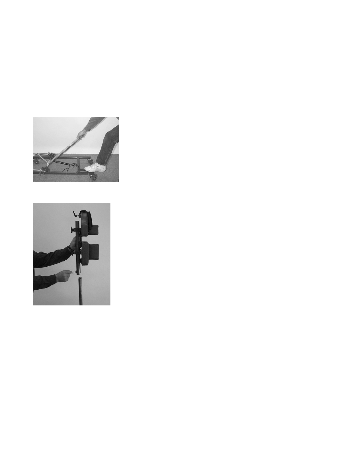
Figure 1
Figure 2
ASSEMBLY
INSTRUCTIONS
Set-up and assembly on your Superstand is easy
when you follow these directions.
First:
Identify the following parts and components and
be sure they are in the carton.
• Base with upright post
• Body support assembly
• Foot support assembly
• Head support and Chin support
Other options: Upper Extremity Positioning Tray;
Size Adjustable Knee Pads.
Assemble as follows:
First: Lock all four casters on the base.
A. Installing the Body Support Assembly:
Warning:
section - it may move into an upright position
rapidly when released.
¿ To release center mast cut white cable ties that
hold it to the base.
¿ Depress foot release lever allowing mast to achieve
its fully upright position
¿ Pull out release ring on Body Support Assembly and
slide onto center mast
¿ Locate center mast height by allowing release ring
to drop into the appropriate hole for the height of
the client.
Take care to keep clear of center mast
(Figure 1)
(Figure 2)
.
.
Superstand OWNER’S MANUAL - 5 - PRIME ENGINEERING
Page 6
g
Fi
ure 3
Figure 4
ASSEMBLY
INSTRUCTIONS
(Continued)
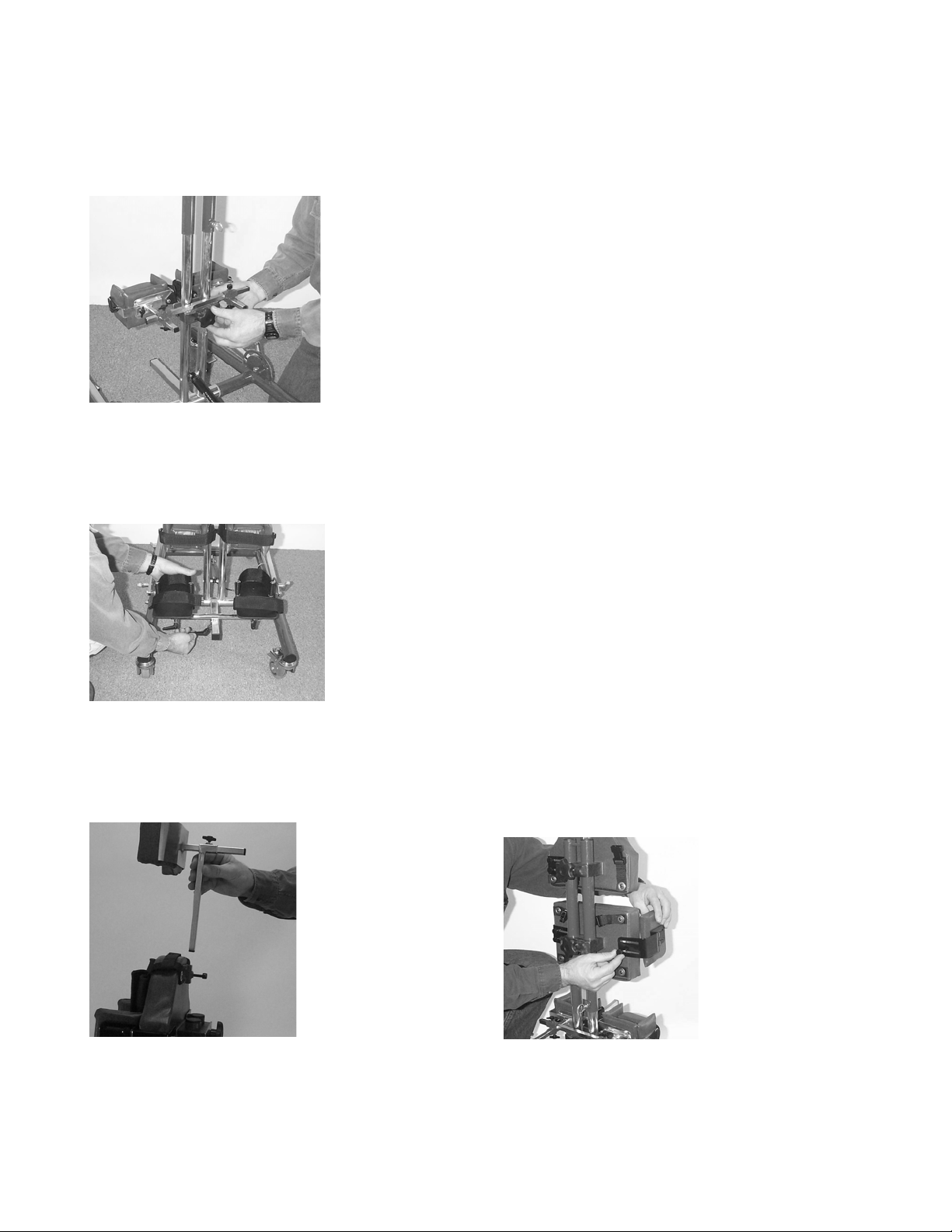
B. Installing Knee Support Assembly:
¿ Remove the adjustment knob from the clamp on
back of the Knee Support Assembly.
¿ Fasten Knee Support Assembly to the center mast
with the 2-piece clamp and reattach the
adjustment knob
(Figure3).
C. Install Foot Assembly:
¿ Loosen large ratchet knob on adjustment block of
Foot Assembly.
¿ Slide onto silver foot assembly receiver tube and
secure with ratchet knob
D. Install Head Support/Chin Support:
¿ Slide appropriate support pad (Head Support for
supine/Chin Support for prone) into receiver tube
at top end of Body Support Assembly and secure
with T-knob
(Figure 5).
E. Attaching Lateral Supports:
¿ Fasten lateral support brackets to backside of
support pads with small black knobs provided
(Figure 6).
F. Superstand assembly is complete and ready to
be adjusted for use.
(Figure 4
).
Figure 5
Superstand OWNER’S MANUAL - 6 - PRIME ENGINEERING
Figure 6
Page 7
FITTING AND
ADJUSTING YOUR
Superstand
WARNING: CONSULT YOUR PHYSICIAN OR THERAPI ST. T his Superstand is to be used ONLY with the approval
and advice of a Physician or Therapist. Standing may cause medical complications in some individuals. Consult with your
Physician or Therapist before standing. Be certain that there are no functional restrictions that might prevent the use of this
product.
Your
Superstand
supine or upright standing. Your physician or
therapist will recommend which approach, will be
the most appropriate. With our “no tools” approach
you are able to set the positioning pads in the
necessary configuration(s) or quickly convert to a
different standing configuration as needed.
MAKE ALL ADJUSTMENTS BEFORE PLACING
THE CLIENT IN THE
ADJUST THE PADS WHILE THE STANDER IS
IN USE.
will allow you to choose prone,
SUPERSTAND
. NEVER
Figure 7
Figure 8
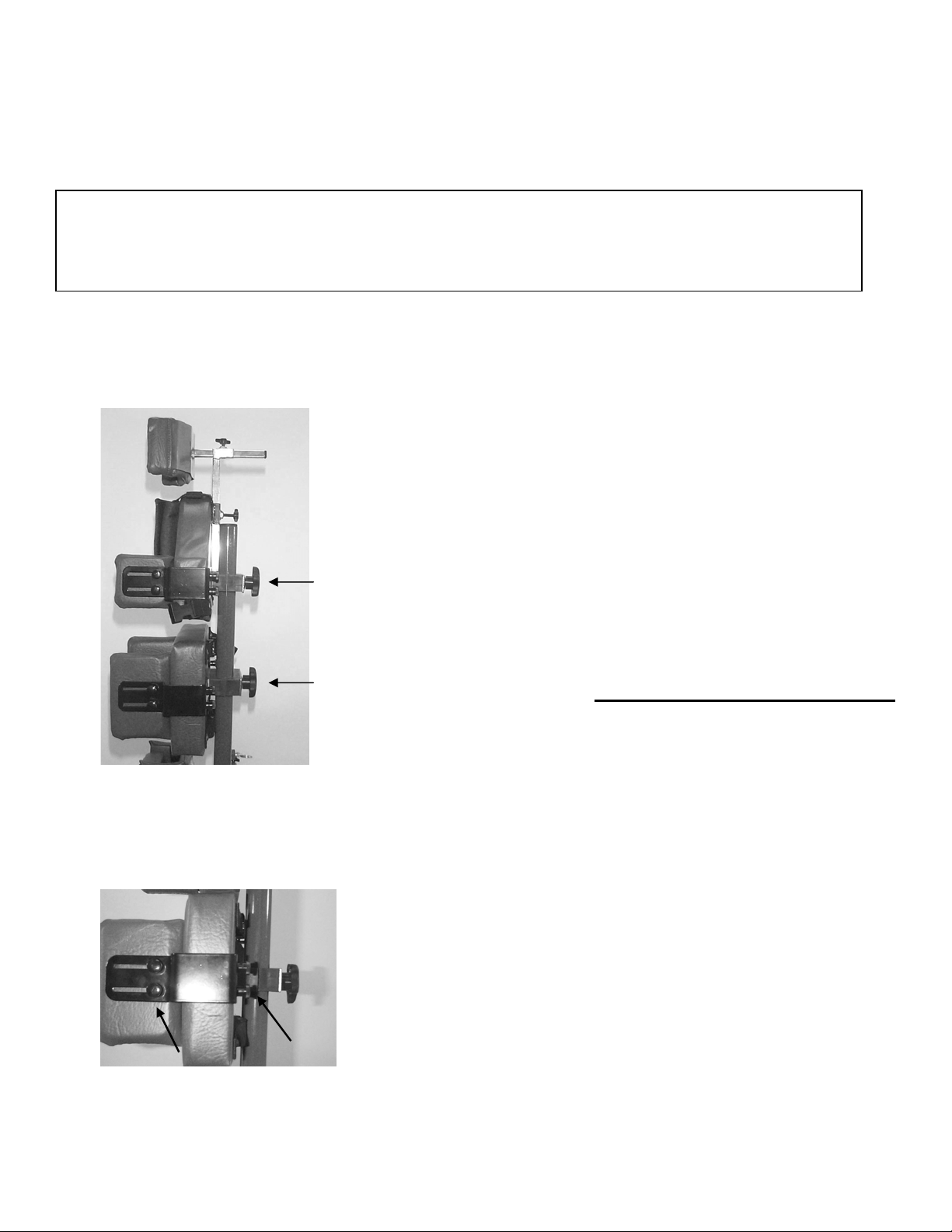
Positioning Pads
Chest and Hip Support Pads:
adjustments for height up or down on the center
mast by loosening the large black adjustment knob
on the back of each pad and sliding the pad to the
position desired
be adjusted by loosening the small black
adjustment knobs on the back of the lateral
support bracket. Slide the brackets to a narrower
or wider setting securing the child’s side-to-side
stability and position. Lateral supports can be
depth adjusted by loosening the small black
adjustment knobs on the side of the bracket and
sliding the pad front or back to the desired
position
(Figure 8).
(Figure 7)
Perform individual
. Lateral supports can
Superstand OWNER’S MANUAL - 7 - PRIME ENGINEERING
Page 8
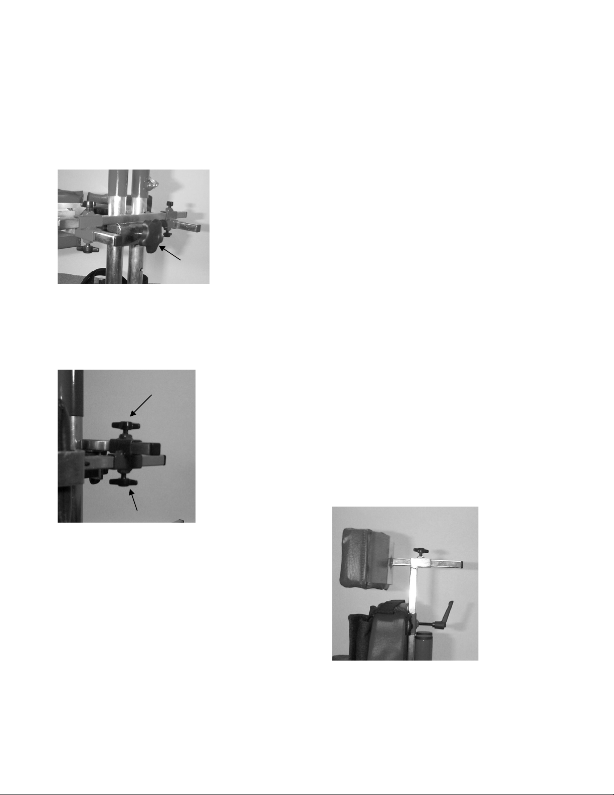
Figure 9
FITTING AND
ADJUSTING YOUR
Superstand
(Continued)
Knee Support Pads:
Pads by loosening the large black adjustment knob
on the back of the Knee Support Assembly and
sliding the assembly up or down on the center mast
(Figure 9)
width or depth by loosening the T-knob on the side
you wish to adjust
front-to-back or side-to-side to accomplish proper
(straight) alignment of the lower extremities.
. Individually adjust for each kneepad
Head Support/Chin Support Pads:
positioning the child in the supine position, slide
the Head Support Pad into the bracket at the
upper end of the chest pad and set to the desired
height
Chin Support Pad can be interchanged with the
head support and set to the desired height.
BE SURE TO SECURELY TIGHTEN ALL
ADJUSTMENT KNOBS BEFORE PLACING THE
CLIENT IN THE STANDER.
(Figure 11)
Adjust the Knee Support
(Figure 10)
. While in prone positioning, the
. Position the pad
When
Figure 10
Superstand OWNER’S MANUAL - 8 - PRIME ENGINEERING
Figure 11
Page 9
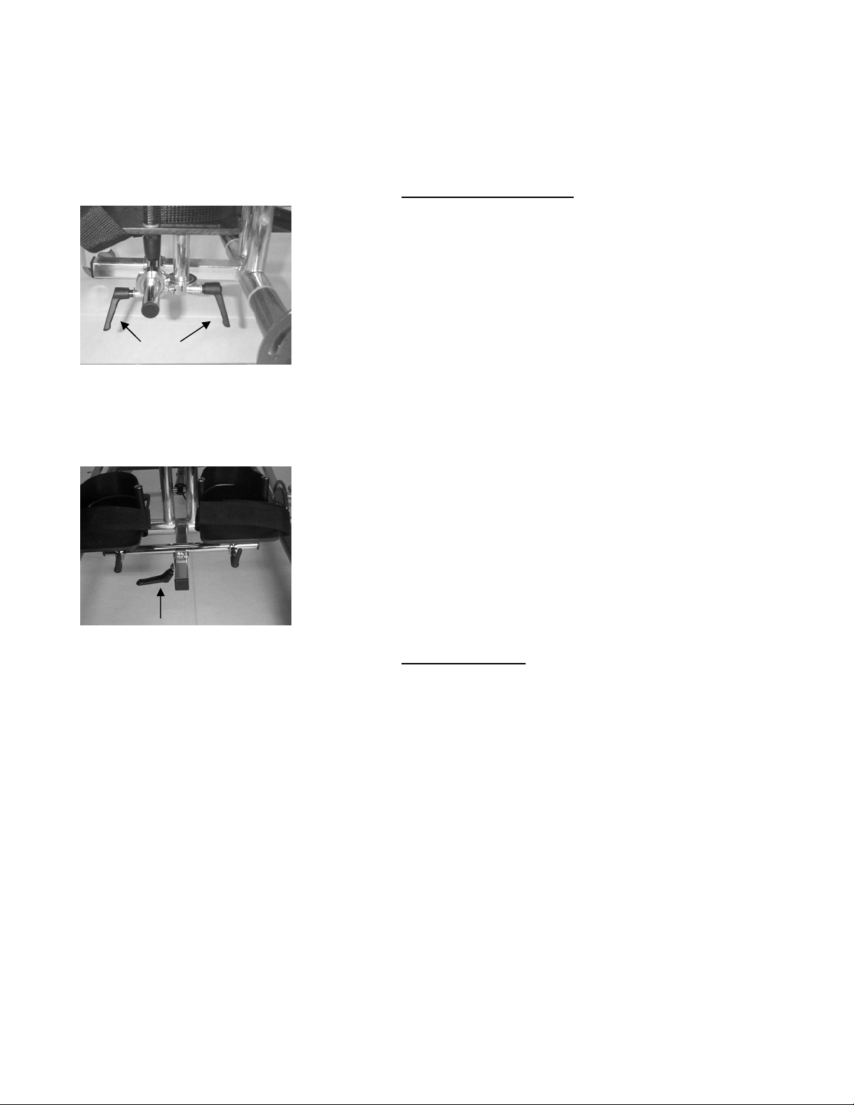
Figure 12
Figure 13
FITTING AND
ADJUSTING YOUR
Superstand
(Continued)
Foot Support System
The Foot Support System is individually adjusted
in height and width with the ratchet knobs found
on each side of the system
foot support up or down or side-to-side to the
desired position maintaining proper alignment for
the lower extremities. These same ratchet knobs
allow for individual angle setting of each foot
support pad for planter or dorsi-flexion plus toe in
and toe out. Front-to-back adjustment is
performed by loosening the ratchet knob on the
underside of the assembly and sliding the assembly
to its desired position
Heel loops and Velcro-adjustable toe straps secure
the placement of the feet on the support
platforms. The entire Foot Support System is
reversible on the center mast, accommodating
either prone or supine positioning.
Support Straps
Chest Support Harness:
around the upper torso of the child once placed in
the stander and attach with the Velcro closure.
Each strap of the chest harness can be additionally
adjusted through the buckles supplied on each
strap. This support can be completely removed by
squeezing the quick release buckles on each strap.
Hip Support Strap:
the client while in the prone position or across the
pelvis of the child while in supine. Secure to the
Hip Support Pad with the buckle and loosen or
tighten for a comfortable, supportive fit.
(Figure 12)
(Figure 13)
Place this harness
Place around the buttocks of
. Slide the
.
Superstand OWNER’S MANUAL - 9 - PRIME ENGINEERING
Page 10
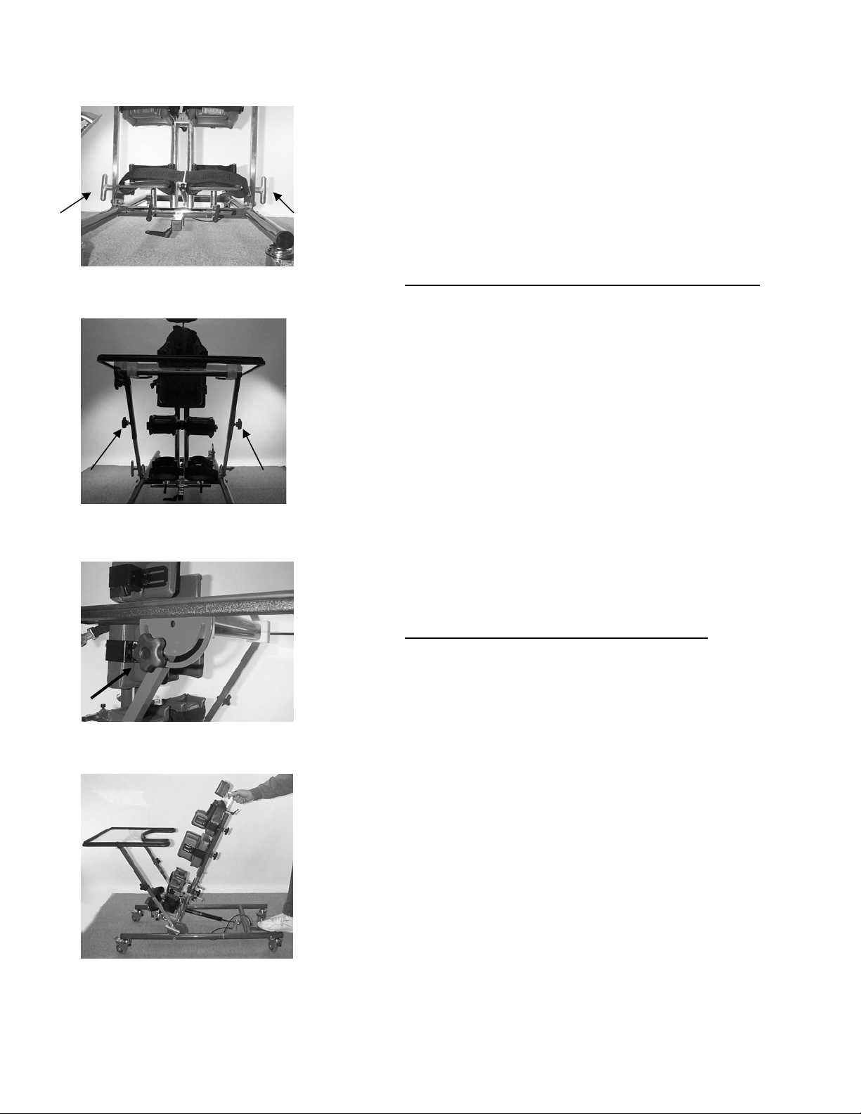
Figure 14
Figure 15
Figure 16
Figure 17
FITTING AND
ADJUSTING YOUR
Superstand
(Continued)
Knee Straps:
easy for comfort and support.
Upper Extremity Positioning Tray (optional)
This multi-functional tray has individual height,
angle and depth adjustments. Positioning of the
entire tray assembly may be adjusted by loosening
the large silver T-knobs on each side near the base
and rotating the assembly to the desired
angle/depth setting
tray can be adjusted by loosening the large black
adjustment knobs in the middle of the tray support
arms and sliding the tray up or down to the desired
height
be adjusted by loosening the large black knob
located beneath the tray surface and rotating the
tray to the desired angle
Positioning System Angle Adjustment
The angle of the complete positioning system can
be set at an adjustment from 10 to 90 degrees
from horizontal. While holding onto the top of the
center mast, depress the foot pedal found on the
base of the stander and move the mast to the
desired angle
adjustment, slide the “lock-out” under the foot
pedal as far as it will go and leave in-place until you
wish to change the angle of the positioning system.
BE SURE ALL ADJUSTMENTS AND KNOBS ARE
TIGHTENED AND SECURE BEFORE PLACING
THE CLIENT IN THE STANDER. NEVER LEAVE
THE CLIENT UNATTENDED WHILE IN THE
STANDER.
(Figure 15)
Velcro adjustments are fast and
(Figure 14)
. The angle of the tray top can
(Figure 16)
(Figure 17)
. To secure the angle
. Height of the
.
Superstand OWNER’S MANUAL - 10 - PRIME ENGINEERING
Page 11

FITTING AND
ADJUSTING YOUR
Superstand
(Continued)
Prime Engineering’s goal is to give you the greatest
amount of adjustment and flexibility maximizing
proper positioning of your client’s standing and
positioning needs. Attention to correct alignment,
proper support and comfort are
accomplishing a successful standing program.
Enjoy your Superstand and all the benefits
experienced from proper standing and positioning.
essential
in
Superstand OWNER’S MANUAL - 11 - PRIME ENGINEERING
Page 12
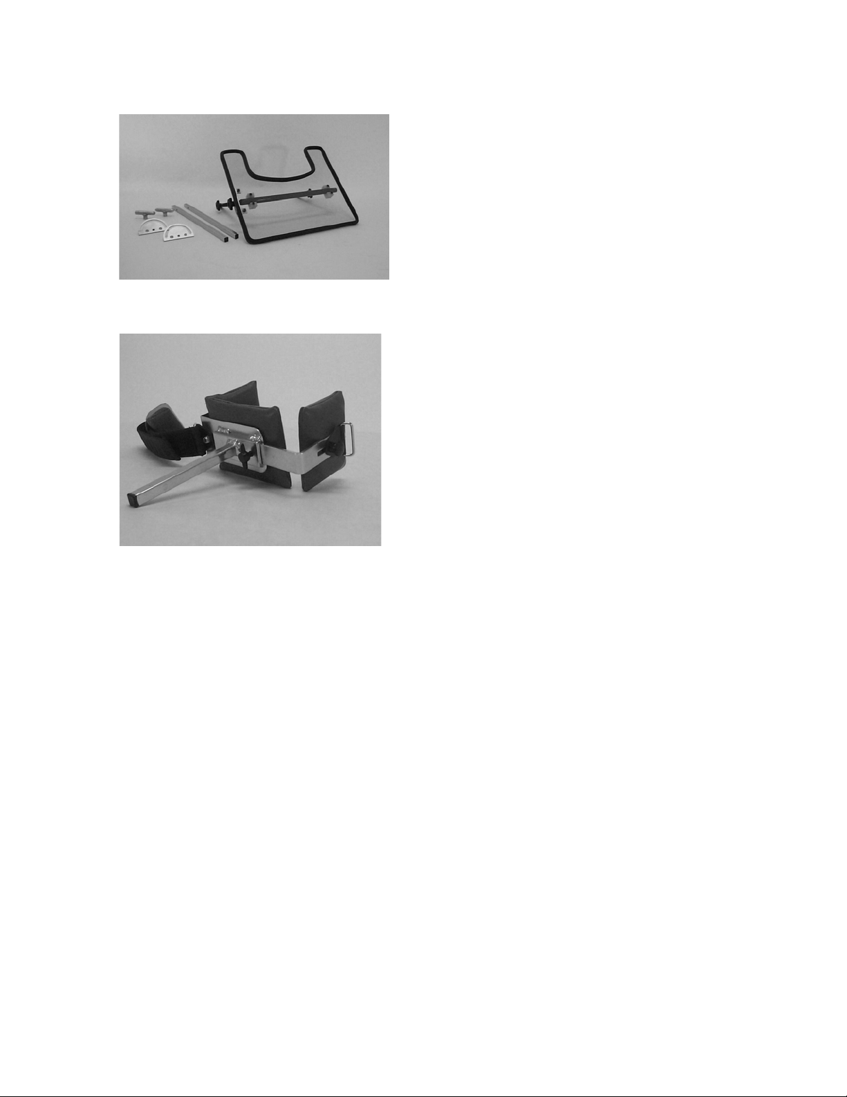
ACCESSORIES
Upper Extremity Positioning
Tray Assembly
Size Adjustable Knee Pads
Superstand OWNER’S MANUAL - 12 - PRIME ENGINEERING
Page 13

GENERAL MAINTENANCE
1. Periodically insure nuts and bolts are secured properly.
2. Keep moving parts clean for free movement. Superstand DOES NOT require
lubrication.
3. Use soft cloth when cleaning table top.
4. DO NOT attempt to make any adjustments while the client is standing in the
Superstand.
5. All fabrics should be hand washed with mild soap and water, then allowed to air dry.
Superstand OWNER’S MANUAL - 13 - PRIME ENGINEERING
Page 14

Superstand, Superstand Youth
Limited Warranty
Effective February 1, 2002
Warranty coverage is extended to the original purchaser for as long as the original purchaser owns the Prime
Engineering system. This warranty is in effect for the Superstand and Superstand Youth (the product) standing frames. Prime
Engineering, Inc. (“the Company”) shall repair, or replace the Product that fails due to defect in material, or workmanship per the
following schedule:
Frames: Lifetime to the original purchaser subject to the following terms, limitations and conditions.
Gas Shocks: One year to the original purchaser subject to the following terms, limitations and conditions.
Straps: One year to the original purchaser subject to the following terms, limitations and conditions.
Other Components: Upholstery, plastic parts, painted surfaces, rubber parts, bearings, casters and other parts not
specifically identified above, all of which are warranted against defects in material and workmanship for three months
from the original purchase date, subject to the following terms and conditions, and limitations.
Warranty Conditions.
warranty registration form should be fully completed by the original retail purchaser / user or their agent, and received by Prime
Engineering at its address set forth on the registration form no later than three months after the original purchase date. Any
defective Product shall be delivered to Prime Engineering, or its local authorized dealer, at purchaser's expense for warranty
inspection. Return freight charges shall be prepaid by Prime Engineering. You may contact Prime Engineering at (800) 8278263 for authorized dealers in or near your location.
This warranty shall be in effect from the original purchase date to the consumer. The
Limitations and Exclusions. The warranty provided above shall not apply to (a) a serial numbered Product if the
serial number has been removed or defaced; (b) any Product subjected to negligence, abuse, misuse, improper operation,
maintenance, or storage, or damages beyond Prime Engineering’s control, as determined by Prime Engineering; (c) defects
arising from purchaser's failure to follow instructions. Any Changes or Additions to the Product of unauthorized parts not
manufactured or furnished by Prime Engineering. The repair or replacement by Prime Engineering for a defective Part or
Product shall be purchaser's sole and exclusive remedy under the warranty. Repair labor/service charges are not covered by
this warranty and are not the responsibility of Prime Engineering.
The foregoing Warranty is exclusive and in lieu of all other warranties, express, implied, or
statutory, including warranties of merchantability and fitness for a particular purpose and design.
In no event shall Prime Engineering be liable for any consequential or incidental damages.
Some states do not allow limitations on how long an implied warranty lasts or the exclusion or limitations of incidental or
consequential damages, so the above limitations or exclusions may not apply to you. This warranty gives you specific legal
rights, and you may also have other rights that vary from state to state.
Prime Engineering
A division of Axiom Industries, Inc.
4202 W. Sierra Madre Avenue
Fresno, CA 93722 USA
Toll-free: 800-827-8263
Fax: 800-800-3355
E-mail: [email protected]
Website: www.primeengineering.com
Superstand Youth OWNER’S MANUAL - 15 - PRIME ENGINEERING
 Loading...