

Page 1

OWNER’S MANUAL
PRODUCT PHOTO
PARTS LIST
ASSEMBLY INSTRUCTIONS
FITTING & ADJUSTING
DAILY USAGE
ACCESSORIES
MAINTENANCE
WARRANTY
Prime Engineering
KIDSTAND III
Manufactured By
Prime Engineering
A Division of Axiom Industries, Inc.
4202 W. Sierra Madre Avenue Fresno, CA 93722 USA
Tel: (559) 276-0991
Toll-free: (800) 82-STAND
Fax: (800) 800-3355
E-Mail: [email protected]
Web Site:
www.primeengineering.com
Modular Standing System
020102KSIIIOM
Page 2

PRIME ENGINEERING
KIDSTAND III MSS
A note from the President:
Prime Engineering’s lead in standing frame technology was
developed from my personal need for a standing device.
With no suitable product on the market to really answer the
needs of proper positioning while standing, the necessity for
safety, comfort and proper standing inspired us to build our
first standing frame… mine! It quickly became clear many
others could benefit from a quality standing frame. We
created Prime Engineering to serve the client needing
standing assistance.
Be sure to take the time to fully acquaint yourself with all the
features of your Kidstand III MSS before standing. Your
body was designed to stand so make sure you stand daily
for your health!
This owner’s manual is organized into:
1. Product photo
2. Parts list
3. Assembly instructions
4. Fitting & adjusting
5. Daily usage
6. Accessories & replacement parts
7. Maintenance
8. Warranty
We’ve designed the Kidstand III MSS for easy assembly. If,
however, you have any problems or need further assistance,
please don’t hesitate to contact your supplier or contact us at
1-800-82-STAND.
CAUTION:
Consult your Physician or Therapist before using the Kidstand III or any other standing device. DO NOT use the Kidstand III
before becoming thoroughly familiar with all the safety warnings and instructions. Consult a Physician or Therapist to
determine the proper adjustments for your Kidstand III. Take the time and do it right.
Kidstand III MSS OWNER’S MANUAL - 2 - PRIME ENGINEERING
Page 3
PRIME ENGINEERING
p
m
p
g
p
g
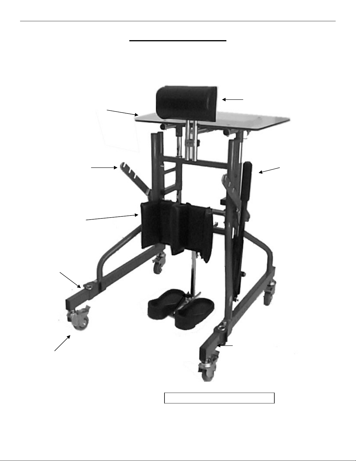
KIDSTAND III MSS HYDRAULIC STANDING FRAME
Chest Pad
Release Pin
Le
Table To
Lift Ar
Kneepad
Pum
Handle
Footpads
andable Frame Le
Ex
Casters
Unit pictured has the steel caster upgrade shown.
Kidstand III MSS OWNER’S MANUAL - 3 - PRIME ENGINEERING
Page 4

The Kidstand III MSS comes partially assembled in two (2)
cartons.
Carton A contains:
(1) Center section assembly
(1) Hydraulic lift unit
(1) Kneepad
Carton B contains:
Hardware package that includes:
1 - Owner’s manual 1 - Seat sling 4 - 5/16” - 18 x 1-3/4” Pan head Allen bolts 4 - 5/16” Washers 4 - 5/16” Acorn nuts 1 - 5/32” Allen wrench 1 - 3/16” Allen wrench 1 - Left side frame 1 - Right side frame 1 - Chest pad 1 - Footpad assembly 1 - Tabletop
In addition to the tools supplied, you will need the following:
1 – 1/2” Open end wrench
1 – 7/16” Open end wrench
1 – 9/16” Open end wrench
1 – 9/16” Socket
PARTS LIST
Kidstand III MSS OWNER’S MANUAL - 4 - PRIME ENGINEERING
Page 5
ASSEMBLY INSTRUCTIONS
Open Box A and B and check to insure all parts match the
parts list.
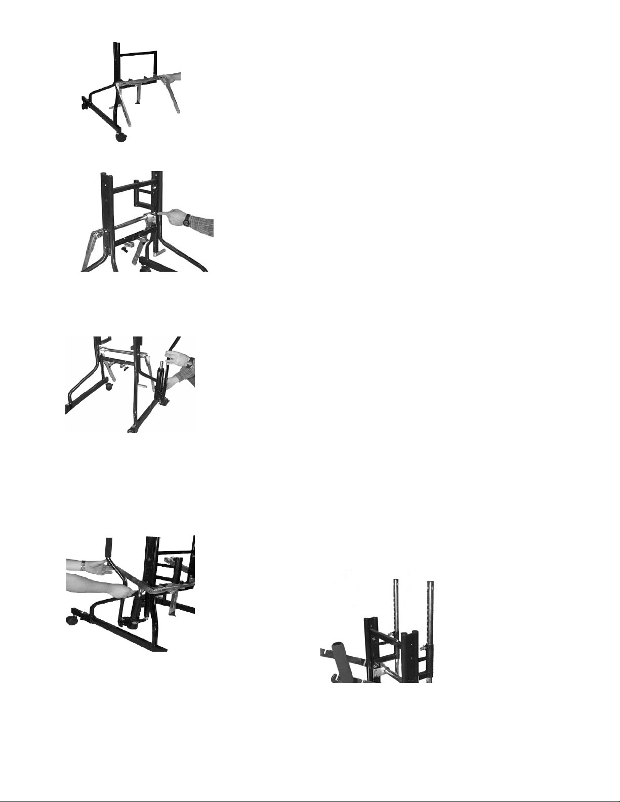
1. Remove center section assembly from Box A
Figure 1
Figure 2
Figure 3
2. With center section in upright position, attach the left and
the right side frames to the center section in the lowest
position using two 5/16 - 18 x 1-3/4” pan head Allen bolts,
two 5/16 washers and two 5/16-18 acorn nuts. Notice:
Hand tighten acorn nuts at this point; they will need to be
removed and reinstalled later. (Figure 1) Side frames
are marked R (right) and L (left) Client must stand
between longest ends of side frames when properly
installed.
3. Remove 5/16 – 18 acorn nut and washer from right side
frame assembly and install right side tray receiver
bracket. Secure with 5/16 – 18 acorn nut and washer
then repeat this procedure for the left side of the frame.
(Figure 2)
4. Slide the hydraulic lift assembly onto the lower mounting
stud. (Figure 3)
5. Attach the hydraulic lift unit to the lift arms with 1/4 - 20
shoulder screw provided and secure with the 1/4 - 20
self-locking nut. (Figure 4)
6. Install height adjustable tray upright poles into tray
receiver bracket. Pull out on locator pin and slide tray
pole into tray receiver bracket. Position both poles so
that they are at the same height from the floor. Make
sure that poles are high enough to clear lift arms when
tray is installed. (Figure 5)
Figure 4
Kidstand III MSS OWNER’S MANUAL - 5 - PRIME ENGINEERING
Figure 5
Page 6
ASSEMBLY
INSTRUCTIONS
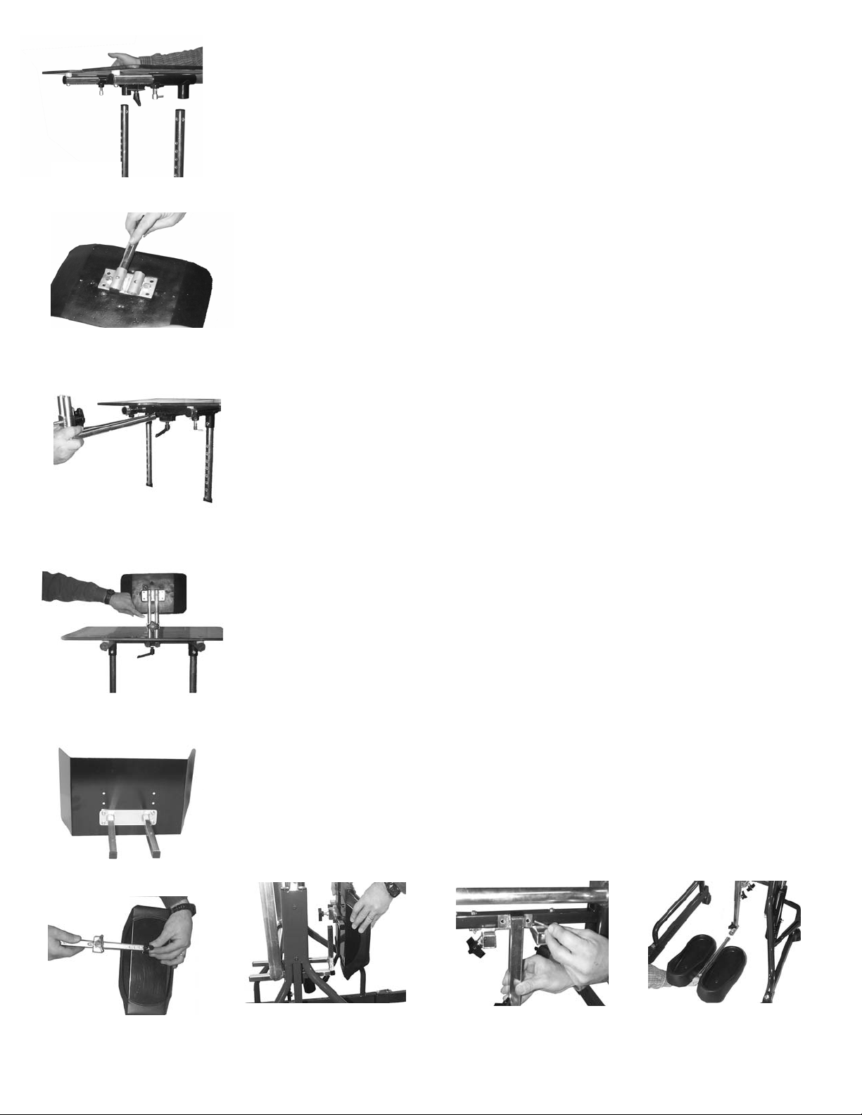
7. Attach the tabletop assembly to the tray support poles
and secure with ¼ - 20 x 1 ¾ hex bolt and ¼ - 20 nyloc
Figure 6
Figure 7
Figure 8
Figure 9
Figure 10
Figure 11 Figure 12 Figure 13 Figure 14
nuts. (Figure 6)
8. Install the vertical adjustment tubes in the chest pad by
depressing the push buttons and inserting the tubes into
the mounting bracket on the chest pad. (Figure 7)
9. Insert the chest pad receiver tube assembly into the
receiver guides and secure with the 5/16 – 18 ratchet
knobs. (Figure 8)
10. Install the chest pad into the chest pad receiver tube
assembly and secure with the 5/16 – 18 rosette knob.
(Figure 9)
11. Standard Knee Pad Assembly
Select location holes on back of kneepad to address
height requirements. Mount depth adjustment bar to
kneepad using 4 each 1/4 - 20 hex bolts. (Figure 10)
Install kneepad into the knee assembly receiver tubes
and secure with black adjustment knobs.
12. Optional Multi-Adjustable Knee System Assembly
Install knee bar mount into the knee assembly receiver
tubes and secure with black adjustment knobs. (Figure
11) Install kneepads onto knee bar and slide assembly
into knee bar mounting tube and secure with black
adjustment knobs. (Figure 12)
13. Standard Foot System
Attach standard foot tube receiver using ¼ - 20 x 1 ½
bolts, nyloc hex nuts and washers. (Figure 13) Install
upright foot tube into foot tube receiver and tighten black
tri-knob. Insert standard footpad assembly into upright
foot tube and tighten black tri-knob. (Figure 14)
Kidstand III MSS OWNER’S MANUAL - 6 - PRIME ENGINEERING
Page 7
FITTING AND ADJUSTING YOUR KIDSTAND III MSS
g
Caution: Consult your Physician or Therapist before using the Kidstand III MSS or any other standing device. DO NOT use the
Kidstand III MSS before becoming thoroughly familiar with all the safety warnings and instructions. Consult a Physician or
Therapist to determine the proper adjustments for your Kidstand III MSS. Take the time and do it right.
BASE
Your Kidstand III MSS has a unique expandable base
allowing for maximum stability and a narrow transport
footing. This base allows for clearance through most
standard doorways.
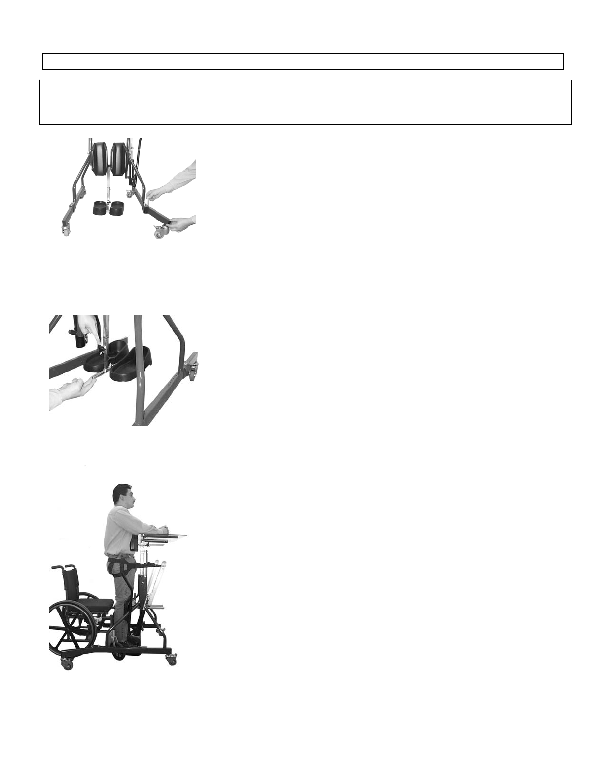
Roll the frame to its desired location and lock both caster
Figure 15
wheels at the front of the base. At the rear of the base there
is a hinge on both sides. Remove the pull pin from the
hinge, open the moveable part of the leg to its outermost
position and replace the pull pin to secure it. (Figure 15)
Lock the casters on the rear of the base.
When desired, move your Kidstand III MSS by adjusting the
base to its narrow setting and secure with pull pins. Unlock
the casters, raise the footpads off the floor and secure with
knob. (Figure 16)
Whenever you stand in your Kidstand III MSS, the footpads
must be placed flat on the floor and all four casters should
be locked in place.
Fi
ure 16
CHEST, KNEE AND FOOT PADS
The chest, knee and footpads should be set so that the body
is properly aligned (straight) while in the standing position.
(Figure 17) Support pads are fully adjustable to insure
maximum comfort and support. The chest, knee, and
footpads can be adjusted front to back by loosening the
black adjustment knobs, locating desired position and retightening adjustment knobs. Chest pad height adjustment
may be obtained by loosening the rosette knob on the back
of the chest pad, raising the pad to the desired position and
re-tighten the knob. The chest pad depth adjustment
brackets may be inverted for additional height range
settings.
Figure 17
Kidstand III MSS OWNER’S MANUAL - 7 - PRIME ENGINEERING
Page 8
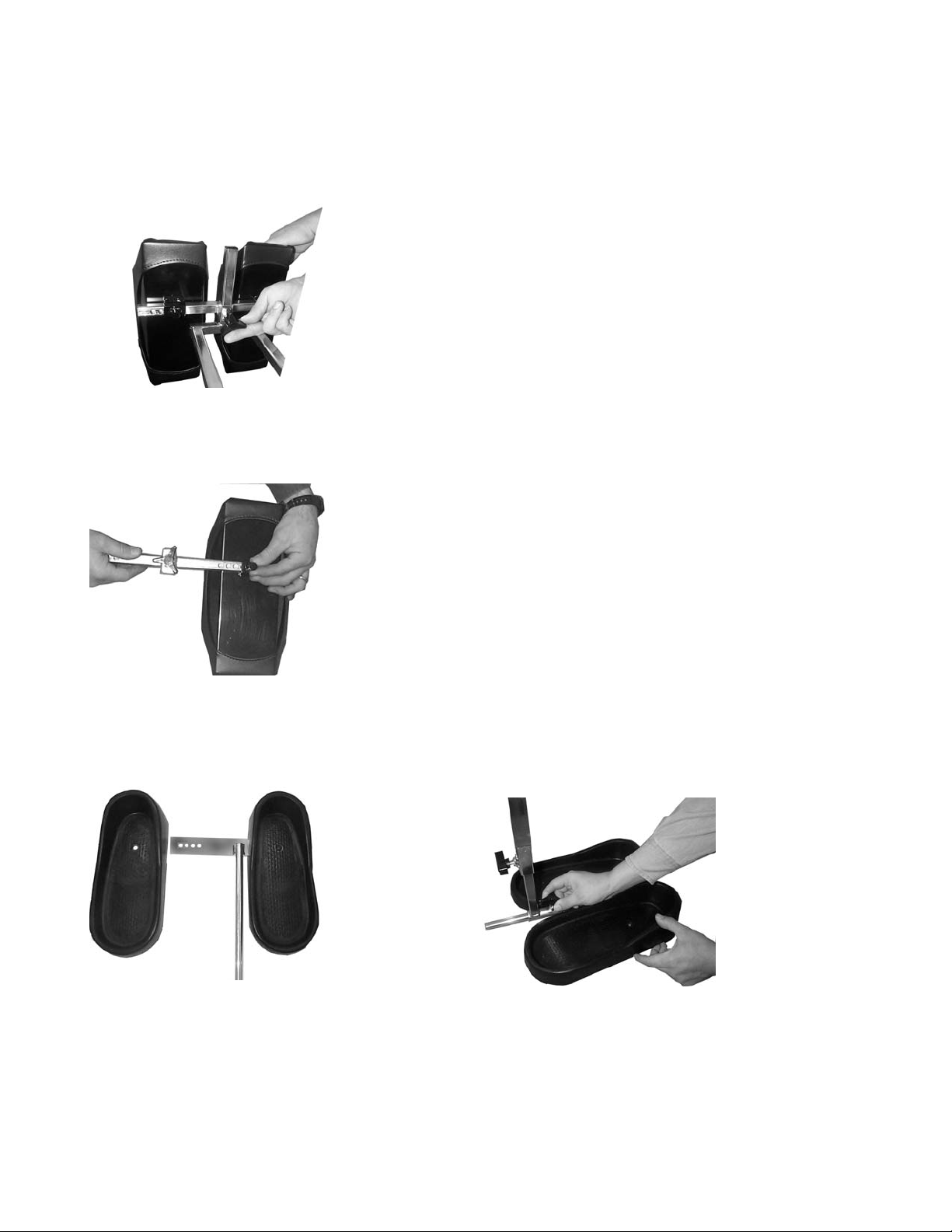
Figure 18
Figure 19
FITTING AND ADJUSTING YOUR KIDSTAND III MSS
(Continued)
Optional Multi-Adjustable Knee System
Kneepad height adjustments are made by loosening the
black adjustment knob on the knee cross bar, moving to the
desired height and securing the adjustment knob.
(Figure 18) Kneepads and/or knee bar mount can be
inverted for additional positioning. Pulling out the pin
located on back of kneepad makes horizontal kneepad
adjustments. Slide pad to the desired position and reinsert
the pin. (Figure 19)
Standard Foot System
Footpad width is adjusted by loosening the footpad bolt
using a 3/16” Allen wrench. Move footpad to 1 of the 4
positioning holes and retighten bolt. (Figure 20) Front to rear
footpad placement is adjusted by securing the footrest guide
rod with the black adjustment knob on the foot receiver tube.
(Figure 21)
Optional Mobile Foot Systems:
If your unit is equipped with any of our optional foot systems,
skip the above step and refer to the instructions that are
included with the foot system you received.
Figure 20
Kidstand III MSS OWNER’S MANUAL - 8 - PRIME ENGINEERING
Figure 21
Page 9
FITTING AND ADJUSTING YOUR KIDSTAND III MSS
Figure 23
Figure 24
Figure 22
(Continued)
B
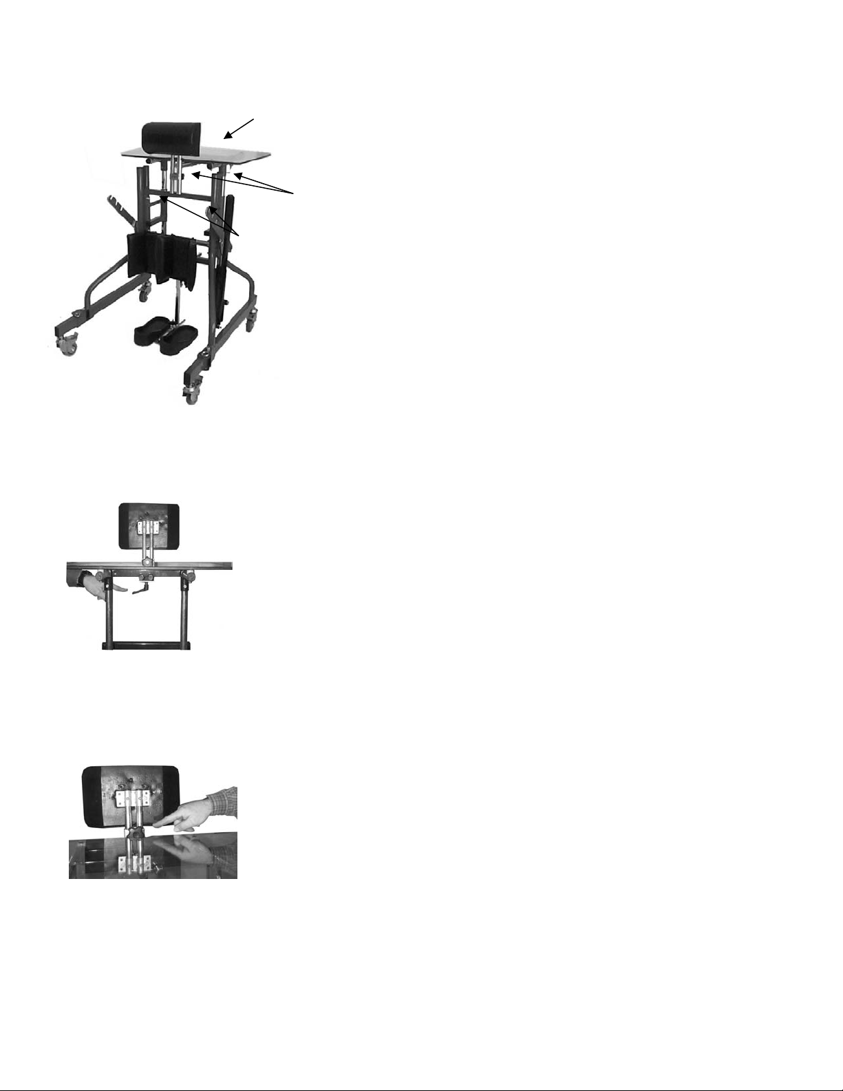
TABLETOP
Tabletop Height:
C
A
1. Pull out one of the 2 locking pins on the tray receiver
bracket and rotate to its locked open position. (Figure
22, Arrow A)
2. While holding the tray assembly up pull out the 2nd
locking pin. Make sure that you have a secure grip on
the tabletop assembly so it does not fall. (Figure 22,
Arrow B)
3. Raise or lower the tabletop assembly to the desired
height and release the locking pin, making sure that the
pin engages into the tabletop height adjustment rail.
4. Release the other locking pin and make sure that the pin
is securely engaged into the tabletop height adjustment
rail.
Tabletop Depth:
1. Adjust the tray depth by pulling down on the 2 locking
pins located under the front edge of the tray support
bracket (Figure 22, Arrow C) and turning them to their
open position.
2. Move the tray to the desired position, return the locking
pins to the locked position making sure that pins fully
engage and stop the tray surface from moving.
CHEST PAD:
Chest Pad Depth:
Loosen the 5/16 – 18 ratchet knob located under the center
of tray support, move chest pad to desired location and
securely tighten ratchet knob. (Figure 23)
Chest Pad Height:
Loosen the 5/16 – 18 rosette knob and raise or lower your
chest pad to the desired location, securely tighten rosette
knob. (Figure 24)
Kidstand III MSS OWNER’S MANUAL - 9 - PRIME ENGINEERING
Page 10
WARNING: CONSULT YOUR PHYSICIAN OR THERAPIST. The Kidstand III is to be used ONLY with the
p
p
g
g
approval and advice of a Physician or Therapist. Standing may cause medical complications in some individuals.
Consult with your Physician or Therapist before standing. Be certain that you do NOT have functional restrictions that
might prevent you from standing.
Pull-to-Place Sling
To
GETTING ON YOUR FEET
The Kidstand III MSS can be used while doing many of your
everyday activities, reading, watching television, eating and
studying. Locate your Kidstand III MSS in your main areas
Bottom
Pull-to-Place Stra
s
of activity.
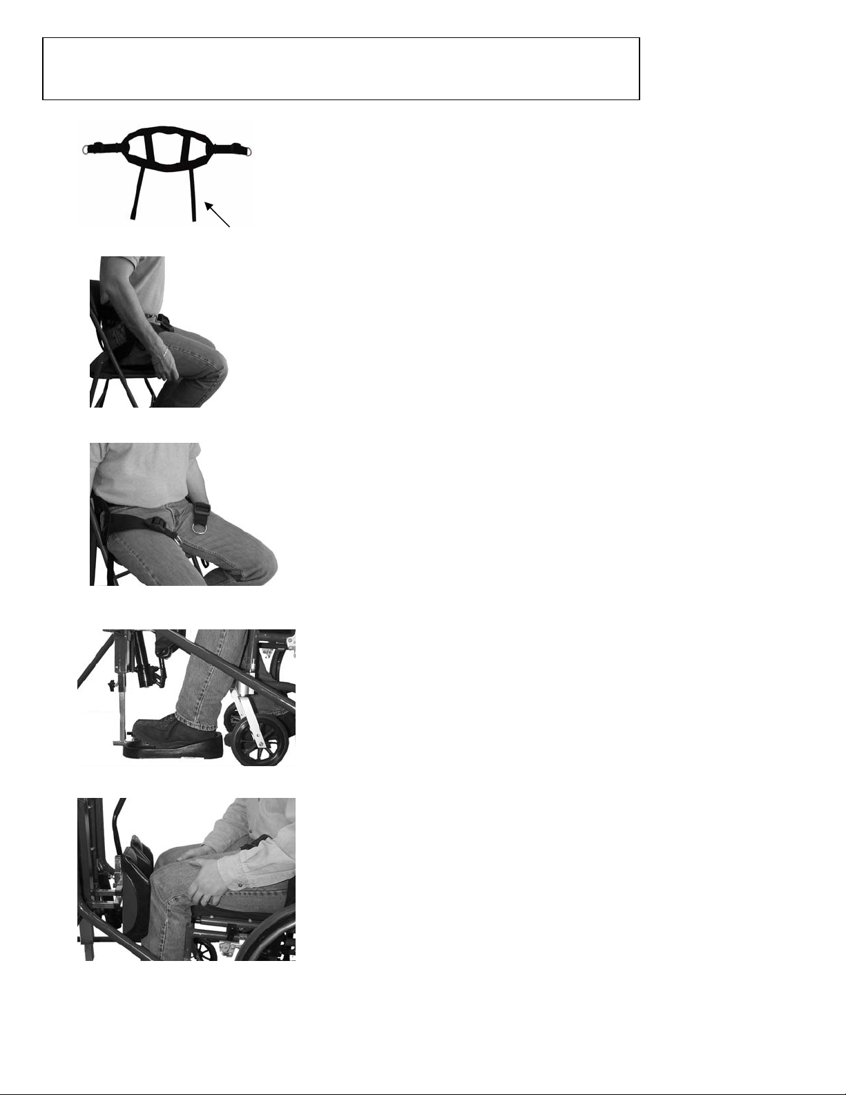
Pull-to-Place Sling Placement:
The Kidstand III MSS is supplied with a Pull-to-Place
sling system allowing you to easily pull the sling into
position without lifting the client. To properly use the
sling, use the following instructions. If you have any
questions regarding the use of this sling, contact your
dealer or call Prime Engineering at 800-827-8263.
Fi
ure 25A
1. Slide the sling all the way down behind the clients back
until it contacts the seating surface. (Figure 25A) NOTE:
Always place the Pull-to-Place straps on the bottom. The
sling will not work properly if placed incorrectly.
2. When the sling makes contact with the seating surface,
pull the Pull-to-Place straps out along both sides of the
legs toward the front of the chair. (Figure 25A)
Figure 25B
3. Make sure that the sling is centered with the two
attachment rings in an equal position in the clients lap.
(Figure 25B)
4. Lean slightly forward and pull down and forward on the
two Pull-to-Place straps pulling the sling into position
under the buttocks. If there is any resistance due to
cushion or clothing, you can lean slightly to the side while
pulling the sling under each side.
Figure 26
5. Remove your wheelchair footplates before approaching
your Kidstand III MSS. Get as close to the footpads as
your chair will allow. Set the wheel locks on your
wheelchair.
6. Place your feet in the footpads and slide your feet to the
rear of the footpad heel cups. (Figure 26)
7. Center your knees into the kneepads. (Figure 27)
Note: Make sure that your knees are in contact with the
kneepads before you start to activate the pump.
Figure 27
DAILY USAGE
Wear comfortable shoes that support your feet. Running or walking “Sports” shoes are recommended.
DO NOT wear hi
Kidstand III MSS OWNER’S MANUAL - 10 - PRIME ENGINEERING
h heels or loose fitting shoes. DO NOT stand without wearing shoes.
Page 11
DAILY USAGE
(Continued)
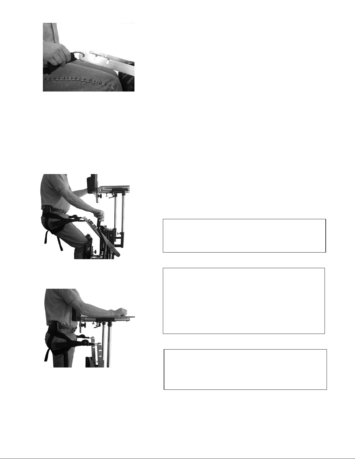
8. Hook the metal seat sling rings into one of the three
notches on the lift arms making sure that there is no
slack in the straps and that the straps are of equal length
on both sides. (Figure 28) Note: The correct notch
placement allows for sling straps to be parallel to the
Figure 28
floor while in the standing position.
Note:
Be certain to use the same notch in both
lift arms. Each side of the Seat Sling
strap needs to be of equal length to
insure a straight, even lift and proper
standing position.
9. Begin to pump yourself up. You are in control of the
speed and height of raising yourself by operating the
handle on the hydraulic pump assembly. (Figure 29)
10. Once you are in a fully upright position, your chest and/or
abdomen should be in firm and comfortable contact with
the chest pad. (Figure 30)
11. To lower yourself, move the pump handle completely
forward to engage the release. You may stop the
lowering at any point by moving the pump handle toward
you.
Figure 29
Figure 30
Note:
The Kidstand III is designed to provide full stability in all
positions from seated to standing. You may stop at any point
while raising yourself to a complete standing position.
Note:
Damage can occur to the pump handle and or hydraulic pump
unit by using it incorrectly.
DO NOT DO THE FOLLOWING:
DO NOT use the pump handle to pull, push or move your frame.
DO NOT push the pump handle side to side.
DO NOT use the pump handle as a support surface.
DO NOT attempt to force the pump handle beyond its normal
operating range in any direction.
Note:
Never pull up on the Lift Arms. This will force air into the
Hydraulic Pump and can cause it to function improperly and
voiding the warranty. ALWAYS pump the Lift Arms up to raise
them.
Kidstand III MSS OWNER’S MANUAL - 11 - PRIME ENGINEERING
Page 12
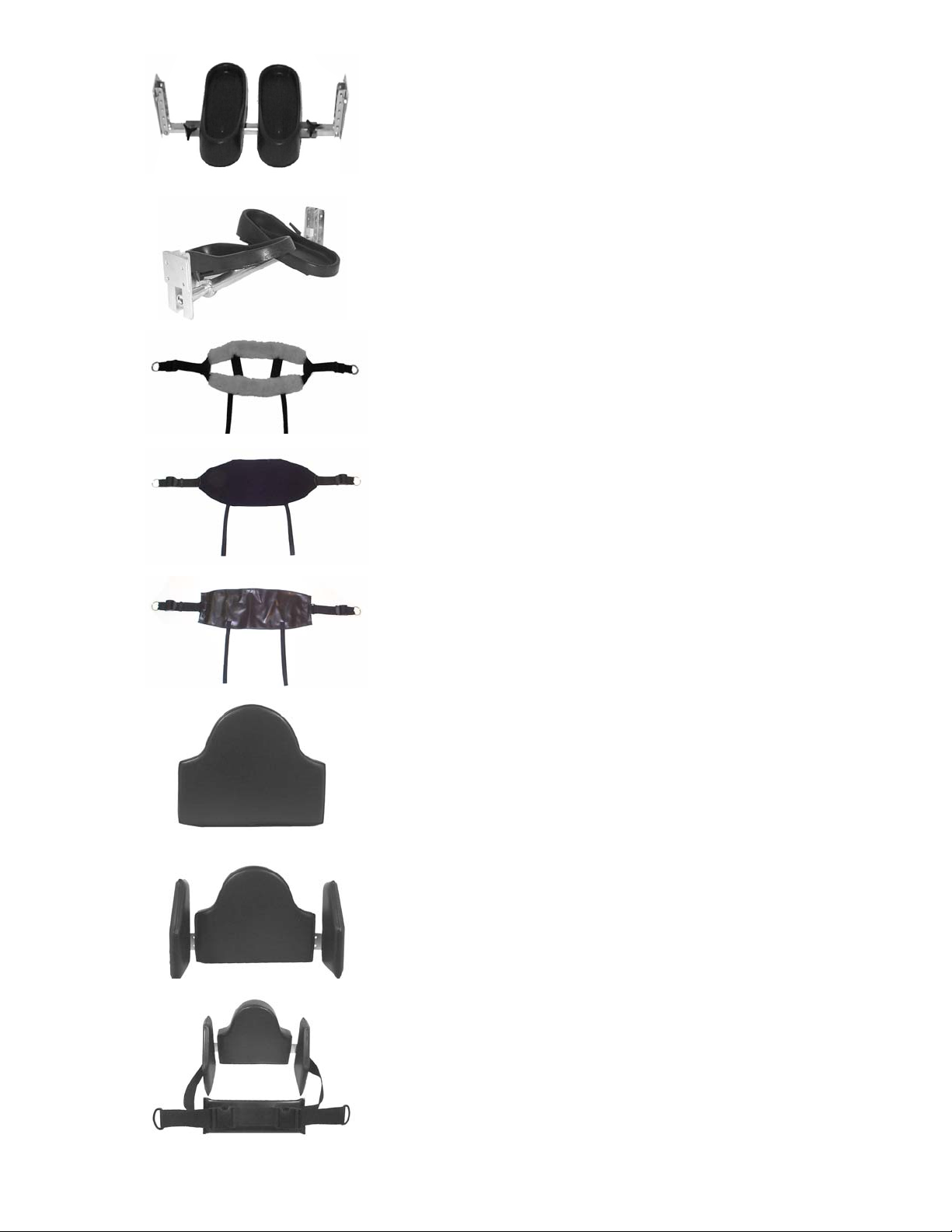
ACCESSORIES
HEIGHT ADJUSTABLE FOOT SYSTEM
Adjusts in width, depth and height for adjustments to
match wheelchair footrest height and allows for
maximum growth potential. Also allows the Kidstand
III MSS to be mobile while in use.
MULTI-ADJUSTABLE FOOT SYSTEM
Adjusts in width, depth, height and angle for complete
adjustment and foot positioning. Also allows the
Kidstand III MSS to be mobile while in use.
SHEEPSKIN SEAT SLING COVER
Provides additional padding.
POCKET SEAT SLING COVER
Solid slipcover with pocket provides greater surface
contact with the ability to add additional padding if
desired.
Kidstand III MSS OWNER’S MANUAL - 12 - PRIME ENGINEERING
VINYL SEAT SLING
Allows greater surface contact and easy cleaning.
CONTOURED BODY PAD
Replaces standard chest support pad providing
additional support for clients with limited upper-body
control.
LATERAL CHEST SUPPORTS
Attaches to chest support pad and provides additional
side support when needed.
CONTOURED BODY PAD WITH LATERALS
AND SUPPORT STRAP
Complete upper body support system supplies
additional upper body support with forward, side to
side and posterior support.
Page 13
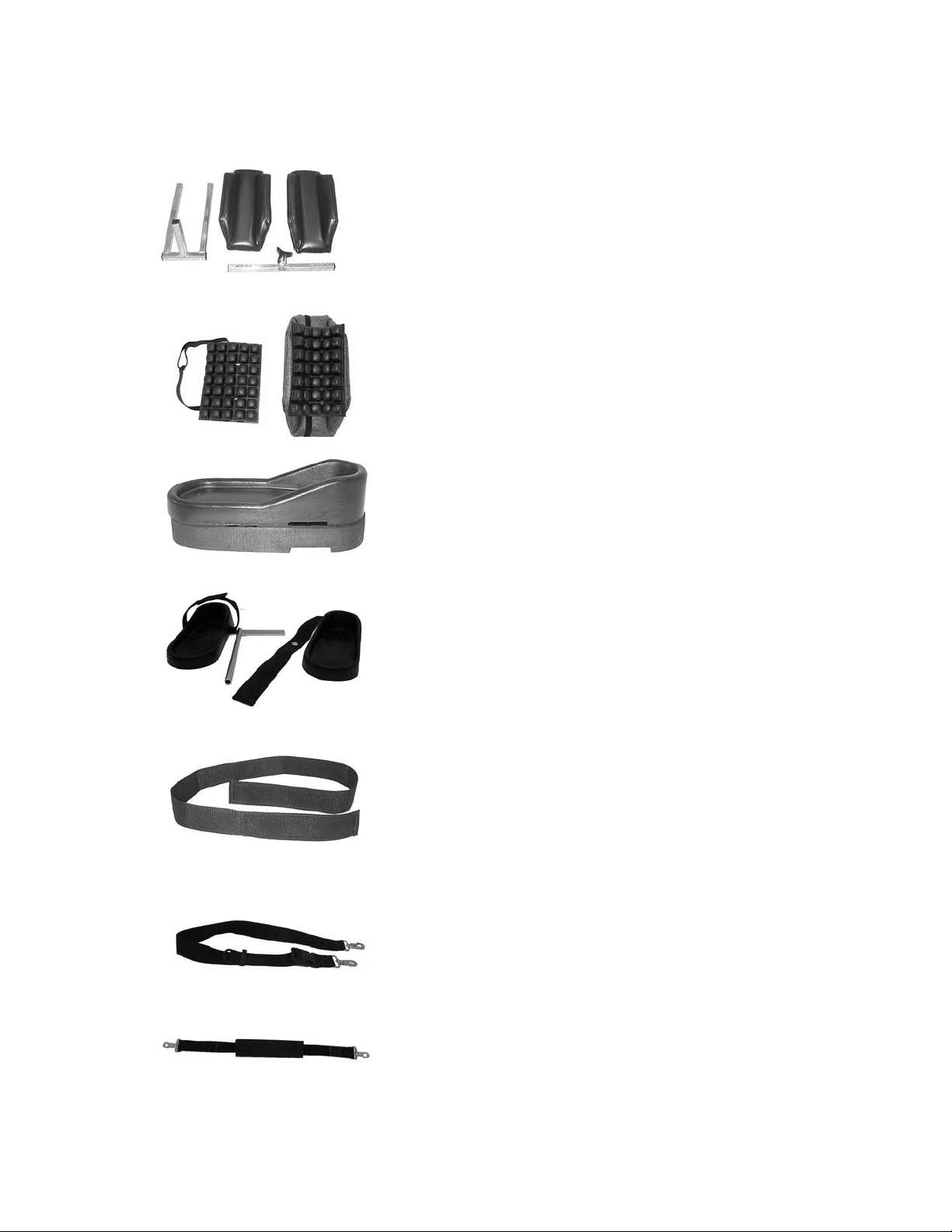
ACCESSORIES
(Continued)
MULTI-ADJUSTABLE KNEE SYSTEM
Offers wide range of height, width and depth
adjustment for maximum positioning needs.
ROHO KNEE PROTECTORS
Attaches with Velcro straps to offer additional padding
in the knee area when needed.
FOOT RISERS
Available in 1 1/2” increments for growth, leg length
discrepancy and other positioning needs.
Kidstand III MSS OWNER’S MANUAL - 13 - PRIME ENGINEERING
FOOT STRAPS
Attaches to footpad and secures foot placement with
Velcro adjustable strap.
CALF STRAP
Secures lower extremity positioning with Velcro
adjustment.
CHEST STRAP
Nylon webbed strap attaches to chest pad and
supplies additional upper body support.
PADDED CHEST STRAP
Supplies additional padded upper body support when
needed.
Page 14

GENERAL MAINTENANCE
1. Periodically insure nuts and bolts are secured properly.
2. Keep moving parts clean for free movement. Kidstand III MSS DOES NOT require
lubrication.
3. Use soft cloth when cleaning tabletop.
4. DO NOT attempt to make any adjustments while standing in your Kidstand III MSS.
5. All fabrics should be hand washed with mild soap and water, then allowed to air dry.
Kidstand III MSS OWNER’S MANUAL - 14 - PRIME ENGINEERING
Page 15

Kidstand III MSS
Limited Warranty
Effective February 01, 2002
Warranty coverage is extended to the original purchaser for as long as the original purchaser owns the Prime
Engineering system. This warranty is in effect for the Kidstand III MSS (the product) standing frame. Prime Engineering, Inc.
(“the Company”) shall repair or replace the Product that fails due to defect in material, or workmanship per the following
schedule:
Frames: Lifetime to the original purchaser subject to the following terms, limitations and conditions.
Hydraulic Actuators: Three years to the original purchaser subject to the following terms, limitations and conditions.
Straps and Slings: One year to the original purchaser subject to the following terms, limitations and conditions.
Other Components: Upholstery, plastic parts, painted surfaces, rubber parts, casters, bearings, and other parts not
specifically identified above, all of which are warranted against defects in material and workmanship for three months
from the original purchase date, subject to the following terms and conditions, and limitations.
Warranty Conditions.
warranty registration form should be fully completed, signed by the original retail purchaser / user or their agent, and received by
Prime Engineering at its address set forth on the registration form no later than three months after the original purchase date.
Any defective Product shall be delivered to Prime Engineering, or its local authorized dealer, at purchaser's expense for
warranty inspection. Return freight charges shall be prepaid by Prime Engineering. You may contact Prime Engineering at
(800) 827-8263 for authorized dealers in or near your location.
This warranty shall be in effect from the original purchase date to the consumer. The
Limitations and Exclusions. The warranty provided above shall not apply to (a) a serial numbered Product if the
serial number has been removed or defaced; (b) any Product subjected to negligence, abuse, misuse, improper operation,
maintenance, or storage, or damages beyond Prime Engineering’s control, as determined by Prime Engineering; (c) defects
arising from purchaser's failure to follow instructions. Any Changes or Additions to the Product of unauthorized parts not
manufactured or furnished by Prime Engineering.
Part or Product shall be purchaser's sole and exclusive remedy under the warranty
charges are not covered by this warranty and are not the responsibility of Prime Engineering.
The repair or replacement by Prime Engineering for a defective
. Repair labor/service
The foregoing Warranty is exclusive and in lieu of all other warranties, express, implied, or
statutory, including warranties of merchantability and fitness for a particular purpose and design.
In no event shall Prime Engineering be liable for any consequential or incidental damages.
Some states do not allow limitations on how long an implied warranty lasts or the exclusion or limitations of incidental or
consequential damages, so the above limitations or exclusions may not apply to you. This warranty gives you specific legal
rights, and you may also have other rights that vary from state to state.
Prime Engineering
A division of Axiom Industries, Inc.
4202 W. Sierra Madre Avenue
Fresno, CA 93722 USA
Toll-free: 800-827-8263
Fax: 800-800-3355
E-mail: [email protected]
Website: www.primeengineering.com
Kidstand III MSS OWNER’S MANUAL - 15 - PRIME ENGINEERING
 Loading...