


 Loading...
BASIC OPERATION INSTRUCTIONS
SynergyTMSeat
ACN# 088 609 661
|
SAFETY GUIDELINES |
2 |
Basic Operation Instructions |
WARNING! A Quantum Rehab Provider or a qualified technician must perform the initial setup of this product and must perform all of the instructions in this manual.
The symbols below are used throughout this owner’s manual and on the power chair to identify warnings and important information. It is very important for you to read them and understand them completely.
WARNING! Indicates a potentially hazardous condition/ situation. Failure to follow designated procedures can cause either personal injury, component damage, or malfunction. On the product, this icon is represented as a black symbol on a yellow triangle with a black border.
MANDATORY! These actions should be performed as specified. Failure to perform mandatory actions can cause personal injury and/or equipment damage. On the product, this icon is represented as a white symbol on a blue dot with a white border.
PROHIBITED! These actions are prohibited. These actions should not be performed at any time or in any circumstances. Performing a prohibited action can cause personal injury and/or equipment damage. On the product, this icon is represented as a black symbol with a red circle and a red slash.
NOTE: These instructions are compiled from the latest specifications and product information available at the time of publication. We reserve the right to make changes as they become necessary. Any changes to our products may cause slight variations between the illustrations and explanations in this manual and the product you have purchased. The latest/current version of this manual is available on our website.
088 609 661
Copyright © 2011
Pride Mobility Products Corporation
INFMANU2015/Rev L/January 2011
Synergy Seat |
www.pridemobility.com |

TABLE OF CONTENTS |
|
Basic Operation Instructions |
3 |
LABEL INFORMATION ................................................................. |
4 |
INTRODUCTION ............................................................................ |
5 |
THE SYNERGY SEAT ................................................................... |
7 |
PRECAUTIONARY GUIDELINES ................................................. |
9 |
SEAT REMOVAL/INSTALLATION ............................................. |
13 |
TOGGLE OPERATION ................................................................ |
16 |
ARMREST OPTIONS .................................................................. |
22 |
Cantilever................................................................................. |
23 |
Flip-Up ..................................................................................... |
25 |
Heavy Duty Drop-In ................................................................. |
27 |
Single Post Quick Height Adjustable Drop-In .......................... |
29 |
Two Post Height Adjustable Flip-Up ........................................ |
32 |
CONTROLLER POSITION .......................................................... |
34 |
POWER SEAT ELEVATOR OPTION .......................................... |
35 |
MANUAL RECLINE OPTION ...................................................... |
36 |
SYNERGY MANUAL TILT OPTION ............................................ |
37 |
CARE AND MAINTENANCE ....................................................... |
38 |
WARRANTY ................................................................................ |
39 |
www.pridemobility.com |
Synergy Seat |
|
LABEL INFORMATION |
4 |
Basic Operation Instructions |
PRODUCT SAFETY SYMBOLS
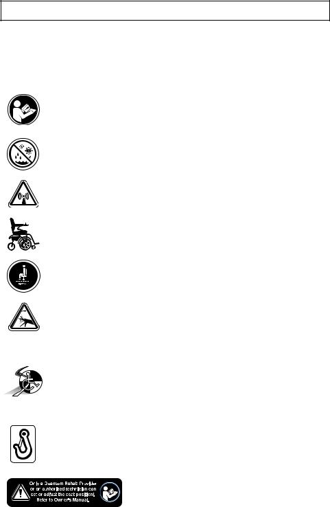
The symbols below are used on the seating system to identify warnings, mandatory actions, and prohibited actions. It is very important for you to read and understand them completely.
Read and follow the information in the owner’s manual.
Avoid exposure to rain, snow, ice, salt, or standing water whenever possible. Maintain and store in a clean and dry condition.
EMI-RFI — This product has been tested and passed at an immunity level of 20 V/m.
Use correct tie-down points for controller harness to prevent the harness from getting caught in the drive tires or pinched in the seat frame.
Maximum seating weight.
Crush/pinch point.
Indicates that this product conforms to the ANSI/RESNA WC/Vol. 4, Section 19/ISO 7176-19 standards for transport of an occupied power chair in a motor vehicle. If this label is not found on this power chair or on the seating system, this indicates that this product is not approved for use as a seat in a motor vehicle. In this case, the power chair occupant must transfer into one of the motor vehicle seats equipped with approved safety belt.
Indicates power chair securement points.
Consult your Quantum Rehab Provider before making any changes to your seating system configuration.
Synergy Seat |
www.pridemobility.com |
Basic Operation Instructions |
5 |
|
|
INTRODUCTION
WELCOME to Quantum Rehab, a division of Pride Mobility Products (Pride). The product you have purchased combines state-of-the-art components with safety, comfort, and styling in mind. We are confident that the design features will provide you with the conveniences you expect during your daily activities. Understanding how to safely operate and care for this product should bring you years of trouble free operations and service.
Read and follow all instructions, warnings, and notes in this manual before attempting to operate your product for the first time. You must also read all instructions, warnings, and notes contained in any supplemental instructional booklets for the controller, front riggings, and/or seating system that accompanied your mobility product before initial operation. Your safety depends upon you, as well as your provider, caretaker, or healthcare professional in using good judgement.
This manual is to be used in addition to the power base owner’s manual that came with your power chair. If there is any information in this manual which you do not understand, or if you require additional assistance for setup or operation, please contact your Quantum Rehab Provider. Failure to follow the instructions, warnings, and notes in this manual and those located on your Pride product can result in personal injury and/or product damage and will void Pride’s product warranty.
PURCHASER’S AGREEMENT
By accepting delivery of this product, you promise that you will not change, alter, or modify this product or remove or render unusable or unsafe any guards, shields, or other safety features of this product; fail, refuse, or neglect to install any retrofit kits from time to time provided by Pride to enhance or preserve the safe use of this product.
INFORMATION EXCHANGE
We want to hear your questions, comments, and suggestions about this manual. We would also like to hear about the safety and reliability of your new Pride product, and about the service you received from your Quantum Rehab Provider. Please notify us of any change of address, so we can keep you apprised of important information about safety, new products, and new options that can increase your ability to use and enjoy your Pride product.
www.pridemobility.com |
Synergy Seat |

6 |
Basic Operation Instructions |
|
|
Please feel free to contact us at the following address:
Pride Mobility Products Corporation
Attn: Customer Care Department
182 Susquehanna Avenue
Exeter, PA 18643-2694
NOTE: If you ever lose or misplace your product registration card or your copy of this manual, contact us and we will be glad to send you a new one immediately.
My Quantum Rehab Provider Is:
Name:
Address:
Phone Number:
Purchase Date:
Synergy Seat |
www.pridemobility.com |
Basic Operation Instructions |
7 |
|
|
THE SYNERGY SEAT
The Synergy Seat is a unique seating system designed specifically for the Pride Power Chair. It is fully adjustable to meet the individual needs of the user, and it is mounted to a Pride power base to provide maximum maneuverability.
Reusable hook and loop fasteners are included in your owner’s package for use in attaching the seat cushion to the seat base. These fasteners are not intended for use on cushions with anti-skid material, as they may damage the seat cushion.
Figure 1 provides information on the Synergy Seat components. Use this diagram to familiarize yourself with the function and location of each component before using the Synergy Seat.
www.pridemobility.com |
Synergy Seat |

8 |
Basic Operation Instructions |
|
|
ATTENDANT CONTROL MODULE (OPTIONAL)
Allows an attendant to control the actuators. Any action made through
the Attendant Control Module overrides the toggle actions made by the user.
ARMRESTS |
Available in five |
Cantilever |
Flip-up |
(standard) |
Heavy Duty Drop-in |
Single Post Quick |
Height Adjustable |
Drop-in |
(available in adult |
and pediatric sizes) |
Two Post Height |
Adjustable Flip-up |
MANUAL TILT |
|
|
MANUAL RECLINE |
|||||||||||||
(OPTIONAL) |
|
|
BACK (OPTIONAL) |
|||||||||||||
With this option, the |
|
|
With this option, the |
|||||||||||||
seatback can be adjusted |
|
|
seatback can be adjusted |
|||||||||||||
to tilt to an angle between |
|
|
to recline to an angle |
|||||||||||||
0 and 45 |
|
|
between 90 and 180 |
|||||||||||||
|
|
|
|
|
|
|
|
|
|
|
|
|
|
|
|
|
|
|
|
|
|
|
|
|
|
|
|
|
|
|
|
|
|
|
|
|
|
|
|
|
|
|
|
|
|
|
|
|
|
|
|
|
|
|
|
|
|
|
|
|
|
|
|
|
|
|
|
|
|
|
|
|
|
|
|
|
|
|
|
|
|
|
|
|
|
|
|
|
|
|
|
|
|
|
|
|
|
|
|
|
|
|
|
|
|
|
|
|
|
|
|
|
|
|
|
|
|
|
|
|
|
|
|
|
|
|
|
|
|
|
|
|
|
|
|
|
|
|
|
|
|
|
|
|
|
|
|
|
|
|
|
|
|
|
|
|
|
|
|
|
|
|
|
|
|
|
|
|
|
|
|
|
|
|
|
|
|
|
|
|
|
|
|
|
|
|
|
|
|
|
|
|
|
|
|
|
|
|
|
|
|
|
|
|
|
|
|
|
|
|
|
|
|
|
|
|
|
|
|
|
|
|
|
|
|
|
|
|
|
|
|
|
|
|
|
|
|
|
|
|
|
|
|
|
|
|
|
|
|
|
|
|
|
|
|
|
|
|
|
|
|
|
|
|
|
|
|
|
|
|
|
|
|
|
|
|
|
|
|
|
|
|
|
|
|
|
|
|
|
|
|
|
|
|
|
|
|
|
|
|
|
|
|
|
|
|
|
|
|
|
|
|
|
|
|
|
|
|
|
|
|
|
|
|
|
|
|
|
|
|
|
|
|
|
|
|
|
|
|
|
|
|
|
|
|
|
|
|
|
|
|
|
|
|
|
|
|
|
|
|
|
|
|
|
|
|
|
|
|
|
|
|
|
|
|
|
|
|
|
|
|
|
|
|
|
|
|
|
|
|
|
|
|
|
|
|
|
|
|
|
|
|
|
|
|
|
|
|
|
|
|
|
|
|
|
|
|
|
|
|
|
|
|
|
4-WAY TOGGLE CONTROLS (OPTIONAL)
Allow the user to control the seat elevator and articulating leg rest actuators (if so equipped).
|
|
|
|
|
|
|
|
|
|
|
|
|
|
|
|
|
|
|
|
|
|
|
|
|
|
|
|
|
|
|
|
|
|
|
|
|
|
|
|
4-way |
|
4-way |
Quad |
||||||
Toggle |
|
Button |
Push-Button |
||||||
|
|
|
|
Toggle |
Control |
||||
LEG RESTS (OPTIONAL)
HIGH PIVOT POWER ELEVATING
LEG RESTS (ELR)
Mimic the motion of the knee during leg elevation.
POWER ARTICULATING LEG RESTS (ALR)
Maintain correct knee-to-heel measurements when user's legs are raised or lowered. 

SWING-AWAY POWER ARTICULATING
LEG RESTS (ALR)
Maintain correct knee-to-heel measurements when user's legs are raised or lowered.
POWER ARTICULATING FOOT PLATFORM (AFP)
Maintains correct knee-to-heel measurements when user's legs are raised or lowered.
Figure 1. Synergy Seat and Options
Synergy Seat |
www.pridemobility.com |

Basic Operation Instructions |
9 |
|
|
PRECAUTIONARY GUIDELINES
Before using the Synergy Seat, please read the following. These guidelines are provided for your benefit and will aid you in the safe operation of the seating system.
Turn off the power before you are seated in the Synergy Seat.
Always have assistance when you are being seated in the Synergy Seat.
Follow all of the procedures and heed the warnings as explained in your power chair owner’s manual.
WARNING! The center of gravity of your seating system was factory set to a position that meets the needs of the demographic majority of users. Your Quantum Rehab Provider has evaluated your seating system and made any necessary adjustments to suit your specific requirements. Do not change your seating configuration without first contacting Pride Mobility Products or your Quantum Rehab Provider.
WARNING! Should the fittings on your Synergy Seating System become loose, report the problem immediately to your Quantum Rehab Provider.
WARNING! Your Synergy Seating System is not approved for use as a seat in any vehicle. Use the seats and occupant restraints provided by the manufacturer of the vehicle.
WARNING! Extreme temperatures can affect the temperature of your seating system components and may cause skin irritation. Use caution when your power chair has been used or stored in an extremely hot or cold environment.
MANDATORY! Do not exceed the weight capacity listed in your power chair manual or 300 lbs. (136 kg), whichever is less. If equipped with a Synergy Seat HD, do not exceed the weight capacity of the power chair or 650 lbs. (295 kg), whichever is less.
WARNING! Possible pinch point hazard! Ensure all ventilator wires and tubes are routed properly to avoid component damage during seat adjustment and power chair operation. Follow the wire routing instructions provided by the manufacturer of the ventilator.
NOTE: The addition of an optional vent tray to your Synergy Seat may change the overall weight, size, and/or center of gravity of your power chair. Do not make any changes to your seating configuration without contacting your Quantum Rehab Provider.
www.pridemobility.com |
Synergy Seat |

10 |
Basic Operation Instructions |
|
|
Motor Vehicle Transport
The Synergy Seat is not approved for use as a seat in a motor vehicle unless the power base is equipped with a manufacturer-approved transit securement system and the seat is labeled to show conformity to the standards of ANSI/ RESNA WC/Vol. 4, Section 19/ISO 7176-19. Pride recommends that the power chair user transfer into the vehicle seat and use the vehicle-installed restraint system if and whenever feasible. The power chair should then be stored and secured in the vehicle. In addition, all removable power chair parts, including the armrests, seat, front riggings, controller, and shrouds should be removed and properly secured during motor vehicle transport.
WARNING! The Synergy Seating System is not approved for use as a seat in any vehicle unless it has been tested and approved for occupied use according to ANSI/RESNA WC/ Vol. 4, Section 19/ISO 7176-19 standards. Use the seats and occupant restraints provided by the manufacturer of the vehicle. If your power chair is equipped with a manufacturer-installed transit securement system, please refer to the supplemental safety information provided with your power chair.
The steel brackets mounted to the front and rear of the Synergy Seating System (see figure 2) can provide securement points when full disassembly and stowage of the power chair is not feasible. These brackets should only be used with an unoccupied power chair that is secured by an approved securement system in accordance with the manufacturer’s instructions. Pride makes no representation of suitability for use with specific securement systems nor can we anticipate the various situations that might arise in use of public transportation systems. For detailed instructions on the use of securement systems, refer to the manufacturer of the system used.
WARNING! The Synergy securement brackets are for unoccupied use only. The power chair occupant must transfer into the vehicle seat and use the vehicle-installed restraint system during motor vehicle transport.
When securing the power chair for unoccupied transport, adhere to the following precautions:
Always ensure that the power chair motors are in drive mode (drive engaged) and that the power chair controller is turned off.
Secure the power chair in a forward-facing position in the vehicle.
Attach tie-down straps (front and rear) only to the provided securement points. Tighten the straps to sufficiently remove all slack.
Synergy Seat |
www.pridemobility.com |
Basic Operation Instructions |
11 |
|
|
WARNING! Never attach tie-downs to adjustable, moving, or removable parts of the power chair such as armrests, front riggings, and wheels.
Position the anchor points for the rear tie-down straps directly behind the rear securement points on the power chair. The front tie-down straps should anchor to floor points that are spaced wider than the power chair to provide increased lateral stability.
WARNING! Ensure unoccupied power chairs are properly secured to the motor vehicle during transport. Power chairs that are not properly secured can become a hazard to vehicle passengers in the event of a crash, sudden stopping, or swerving, as the power chair could tip or slide out of place.
Figure 2. Unoccupied Securement Brackets on a Synergy Seat
www.pridemobility.com |
Synergy Seat |

12 |
Basic Operation Instructions |
|
|
Electromagnetic and Radio Frequency Interference (EMI/RFI)
WARNING! Laboratory tests have shown that electromagnetic and radio frequency waves can have an adverse effect on the performance of electrically-powered mobility vehicles.
Electromagnetic and Radio Frequency Interference can come from sources such as cellular phones, mobile two-way radios (such as walkie-talkies), radio stations, TV stations, amateur radio (HAM) transmitters, wireless computer links, microwave signals, paging transmitters, and medium-range mobile transceivers used by emergency vehicles. In some cases, these waves can cause unintended movement or damage to the control system. Every electrically-powered mobility vehicle has an immunity (or resistance) to EMI. The higher the immunity level, the greater the protection against EMI. This product has been tested and has passed at an immunity level of 20 V/m.
WARNING! Be aware that cell phones, two-way radios, laptops, and other types of radio transmitters may cause unintended movement of your electrically-powered mobility vehicle due to EMI. Exercise caution when using any of these items while operating your mobility vehicle and avoid coming into close proximity of radio and TV stations.
WARNING! The addition of accessories or components to the electrically-powered mobility vehicle can increase the susceptibility of the vehicle to EMI. Do not modify your power chair in any way not authorized by Pride.
WARNING! The electrically-powered mobility vehicle itself can disturb the performance of other electrical devices located nearby, such as alarm systems.
NOTE: For further information on EMI/RFI, go to the Resource Center on www.pridemobility.com. If unintended motion or brake release occurs, turn your power chair off as soon as it is safe to do so. Call Pride or contact your Quantum Rehab Provider to report the incident.
Synergy Seat |
www.pridemobility.com |
Basic Operation Instructions |
13 |
|
|
SEAT REMOVAL/INSTALLATION
The Synergy Seat can be disconnected from the power base to aid in transport or storage.
WARNING! Removing and installing your seating system should be accomplished with no fewer than two people.
To remove the Synergy Seat from the power base:
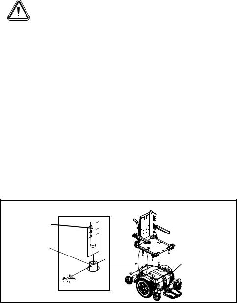
1.Remove the safety snap pins from all of the seat mount connectors. See figure 3.
2.Lift the Synergy Seat. One person should lift from the front of the seat and another should lift from the rear. Lift the seat straight up out of the seat mount connectors.
To install the Synergy Seat on the power base:
1.Lift the Synergy Seat above the power base. One person should lift from the front of the seat and another should lift from the rear.
2.Lower the seat so that the four seat towers are inserted into the four seat mount connectors. See figure 3.
3.Without removing the seat towers from the seat mount connectors, lift either the front or rear of the Synergy Seat and insert the safety snap pins to lock the seat at the desired height.
4.If an angled seat is desired, set the front of the Synergy Seat higher than the rear. The seat base angle can be adjusted to achieve up to 20° of posterior tilt (seat dump).
NOTE: You may need to loosen the setscrews on the seat mount connectors on some power chairs.
SEAT TOWER
SEAT MOUNT CONNECTOR
POWER BASE
SAFETY
SNAP PIN 


Figure 3. Seat Installation/Removal
www.pridemobility.com |
Synergy Seat |
14 |
Basic Operation Instructions |
|
|
To remove the Synergy Seat from the Q6 Edge power base:
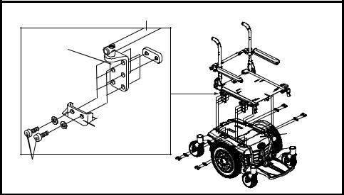
1.Remove the screws from all of the seat interface weldments. See figure 4.
2.Lift the Synergy Seat. One person should lift from the front of the seat and another should lift from the rear. Lift the seat straight up out of the seat interface weldments.
To install the Synergy Seat on the Q6 Edge power base:
1.Lift the Synergy Seat above the power base. One person should lift from the front of the seat and another should lift from the rear.
2.Lower the seat so that the four seat mounting brackets are inserted into the four seat interface weldments. See figure 4.
3.Without removing the seat mounting brackets from the seat interface weldments, lift either the front or rear of the Synergy Seat and insert the screws to lock the seat at the desired height.
4.If an angled seat is desired, set the front of the Synergy Seat higher than the rear. The seat base angle can be adjusted to achieve up to 20° of posterior tilt (seat dump).
TRAPEZE BAR |
|
|
SEATMOUNTING |
|
|
BRACKET |
|
|
SEATINTERFACE |
POWER BASE |
|
WELDMENT |
||
|
||
SCREWS |
|
Figure 4. Seat Installation/Removal on Q6 Edge
Synergy Seat |
www.pridemobility.com |
Loading...