

Page 1

SOFTWARE VERSION 3.6
WWW.PRG.COM
VX76 SOFTWARE
USER MANUAL
Page 2

AutoPar®, Bad Boy®, Best Boy 4000®, PRG Series 400®, MBOX®, MBOX Extreme®, OHM™, Super Node™, V476®, V676®, Virtuoso®,
Virtuoso® DX, Virtuoso® DX2, and VL6C+™ are trademarks of Production Resource Group, LLC, registered in the U.S. and other countries.
Mac®, QuickTime® and FireWire® are registered trademarks of Apple Computer, Inc.
All other brand names which may be mentioned in this manual are trademarks or registered trademarks of their respective companies.
This manual is for informational use only and is subject to change without notice. Please check www.prg.com for the latest version.
PRG assumes no responsibility or liability for any claims resulting from errors or inaccuracies that may appear in this manual.
Vx76 Software User Manual
Version as of: March 22, 2013
PRG part number: 02.9814.0001.36
Production Resource Group, LLC
Dallas Office
8617 Ambassador Row, Suite 120
Dallas, Texas 75247
www.prg.com
Vx76 Software User Manual
©2013 Production Resource Group, LLC. All Rights Reserved.
Page 3

FOREWORD
End User Software License
PLEASE READ THIS DOCUMENT CAREFULLY BEFORE ACTIVATING, COPYING, INSTALLING, OR USING THIS
SOFTWARE PROVIDED BY PRODUCTION RESOURCE GROUP, LLC. BY ACTIVATING, COPYING, INSTALLING, OR
USING THIS SOFTWARE, YOU ARE AGREEING TO BE BOUND BY THE TERMS OF THIS LICENSE. IF YOU DO NOT
AGREE TO THE TERMS OF THIS LICENSE, DO NOT ACTIVATE, COPY, INSTALL, OR USE THIS SOFTWARE AND
PROMPTLY RETURN IT FOR A REFUND.
1) License
software and related documentation (collectively, the "Software") solely with the console sold in conjunction with
the Software. PRG retains all right, title and interest to the Software which is protected by various proprietary
rights, including but not limited to copyrights, trade secrets, or patents ("Proprietary Rights"). No license, right or
interest in any trademark, trade name or service mark of PRG or any third party is granted under this License.
2) No Implied License
license to use, modify or improve any of PRG’s patented technology, copyrights, trade secrets, trademarks, and/
or other Proprietary Rights.
3) Restrictions
copyright, trade secret, and/or other Proprietary Rights, and constitutes valuable property of PRG. You
acknowledge that the Software is disclosed in circumstances of confidence and only for use by you under the
terms and conditions of this License and that you do not acquire any rights of ownership or title in the Software.
You may not attempt to create or derive source codes by disassembly, reverse engineering or any other method,
or otherwise reduce the Software to a human-perceivable form. You may not modify or translate any part of the
Software. You may not use, disclose, distribute, make or have made any copies of the Software, in whole or in
part, without the prior written authorization of PRG. You agree to make reasonable efforts to notify and inform
your employees or agents having access to the Software of your limitations, duties and obligations regarding nondisclosure and copying of the Software. The Software shall be used only by you, your employees or your
authorized agents. You agree to provide notice to PRG immediately after learning of or having reason to suspect
a breach of any of the restrictions set forth in this License.
4) Termination
the Software, and all copies thereof. This License will terminate immediately without notice from PRG if you fail to
comply with any provision of this License. Upon termination, you must destroy the Software and all copies
thereof.
5) Export Control Requirements
License, is made subject to any restrictions concerning the export of products or technical data from the United
States of America which may be imposed upon PRG or you from time to time by the Government of the United
States of America. Furthermore, you agree that at no time, either during the term of this License or thereafter, will
you knowingly export, directly or indirectly, any United States source technical data acquired from PRG under this
License or any direct products of that technical data to any country for which the U.S. Government or any agency
thereof at the time of export requires an export license or other governmental approval, without first obtaining that
license or approval when required by applicable United States law.
6) Limited Warranty
and workmanship under normal use for a period of ninety (90) days from the date of purchase as evidenced by a
copy of your receipt. PRG’s entire liability and your exclusive remedy will be replacement of a media that does
not meet PRG’s limited warranty and is returned at your expense, along with a copy of your receipt, to PRG
customer support or to PRG’s authorized representative. If replacement of the media is not reasonably practical
or commercially reasonable as determined solely in the discretion of PRG, PRG will refund the purchase price as
evidenced by a purchase receipt. PRG will have no responsibility to replace media damaged by accident, abuse
or misapplication. EXCEPT FOR THE FOREGOING, THE SOFTWARE AND RELATED DOCUMENTATION ARE
PROVIDED "AS IS," WITHOUT ADDITIONAL WARRANTY OF ANY KIND, AND PRG EXPRESSLY DISCLAIMS ALL
OTHER WARRANTIES, EXPRESS OR IMPLIED, INCLUDING, BUT NOT LIMITED TO, THE IMPLIED
WARRANTIES OF DESIGN, MERCHANTABILITY, FITNESS FOR A PARTICULAR PURPOSE, OR TITLE, ANY
. Production Resource Group, LLC. ("PRG") hereby grants you a limited license to install and use the Vx76
. You acknowledge that this License in no way shall be construed to provide an implied
. The Software contains proprietary information that is possibly protected by a combination of patent,
. This License is effective until terminated. You may terminate this License at any time by destroying
. This License, and any technical information supplied during the term of this
. PRG warrants the media on which the Software is recorded to be free from defects in materials
VX76 SOFTWARE USER MANUAL I
Page 4

WARRANTIES ARISING FROM A COURSE OF DEALING, USAGE, OR TRADE PRACTICE, OR ANY
WARRANTIES OF NON-INFRINGEMENT OF ANY THIRD PARTY'S PATENT(S), TRADE SECRET(S),
COPYRIGHT(S) OR OTHER INTELLECTUAL PROPERTY RIGHTS. PRG DOES NOT WARRANT THAT THE
FUNCTIONS CONTAINED IN THE SOFTWARE WILL MEET YOUR REQUIREMENTS, OR THAT THE OPERATION
OF THE SOFTWARE WILL BE UNINTERRUPTED OR ERROR-FREE, OR THAT DEFECTS IN THE SOFTWARE
WILL BE CORRECTED. FURTHERMORE, PRG DOES NOT WARRANT OR MAKE ANY REPRESENTATIONS
REGARDING THE USE OR THE RESULTS OF THE USE OF THE SOFTWARE OR RELATED DOCUMENTATION IN
TERMS OF THEIR CORRECTNESS, ACCURACY, RELIABILITY, OR OTHERWISE. NO ORAL OR WRITTEN
INFORMATION OR ADVICE GIVEN BY PRG OR ITS AUTHORIZED REPRESENTATIVE SHALL CREATE ANY
WARRANTY OR IN ANY WAY INCREASE THE SCOPE OF THIS WARRANTY. SHOULD THE SOFTWARE PROVE
DEFECTIVE, YOU (AND NOT PRG OR ITS AUTHORIZED REPRESENTATIVE) ASSUME THE ENTIRE COST OF
ALL NECESSARY SERVICING, REPAIR OR CORRECTION. SOME STATES DO NOT ALLOW EXCLUSION OF
IMPLIED WARRANTIES, SO THE ABOVE EXCLUSION MAY NOT APPLY TO YOU. THIS WARRANTY GIVES YOU
SPECIFIC LEGAL RIGHTS, AND YOU MAY ALSO HAVE OTHER RIGHTS WHICH VARY FROM STATE TO STATE.
7) Limitation Of Liability
. UNDER NO CIRCUMSTANCES, INCLUDING NEGLIGENCE, SHALL PRG BE LIABLE FOR
ANY LOST REVENUE OR PROFITS OR ANY INCIDENTAL, INDIRECT, SPECIAL, OR CONSEQUENTIAL
DAMAGES THAT RESULT FROM THE USE OR INABILITY TO USE THE SOFTWARE OR RELATED
DOCUMENTATION, EVEN IF PRG OR ITS AUTHORIZED REPRESENTATIVE HAS BEEN ADVISED OF THE
POSSIBILITY OF SUCH DAMAGES. SOME STATES DO NOT ALLOW THE LIMITATION OR EXCLUSION OF
LIABILITY FOR INCIDENTAL OR CONSEQUENTIAL DAMAGES SO THE ABOVE LIMITATION OR EXCLUSION
MAY NOT APPLY TO YOU. IN NO EVENT SHALL PRG’S TOTAL LIABILITY TO YOU FOR ALL DAMAGES,
LOSSES, AND CAUSES OF ACTION, WHETHER IN CONTRACT, TORT (INCLUDING NEGLIGENCE) OR
OTHERWISE, EXCEED THE AMOUNT PAID BY YOU FOR THE SOFTWARE.
8) Arbitration, Jurisdiction, and Venue
. You agree that any action at law or in equity arising out of the License or
relating to this Software shall be resolved, individually, through biding arbitration using the then current rules of
the American Arbitration Association, in Dallas, Texas and the resulting decisions may be entered in any court with
proper jurisdiction. This means that if you have a grievance with us, you cannot take us to court, and you may not
join your action with any other party. You can address such grievances through arbitration only and you are
hereby consenting to do it in Dallas, Texas, using Texas' laws (without regard to Texas' conflicts of laws). You
agree that are properly subject to the jurisdiction of the courts of the State of Texas and waive any rights to
challenge personal jurisdiction.
9) Government Licensee
. If you are acquiring the Software on behalf of any unit or agency of the United States
Government, the following provisions apply: (a) the Government acknowledges PRG’s representation that the
Software and its documentation were developed at private expense and no part of them is in the public domain;
(b) the Government acknowledges PRG’s representation that the Software is "Restricted Computer Software" as
that term is defined in Clause 52.227-19 of the Federal Acquisition Regulations ("FAR") and is "Commercial
Computer Software" as that term is defined in Subpart 227.471 of the Department of Defense Federal Acquisition
Regulation Supplement ("DFARS"). The Government agrees that: (i) if the Software is supplied to the Department
of Defense ("DoD"), the Software is classified as "Commercial Computer Software" and the Government is
acquiring only "limited rights" in the Software and its documentation as that term is defined in Clause 252.2277013(a)(13) of the DFARS, and (ii) if the Software is supplied to any unit or agency of the United States
Government other than DoD, the Government’s rights in the Software and its documentation will be as defined in
Clause 52.227-19(c)(2) of the FAR.
10) Indemnity
. You agree to indemnify and hold harmless PRG, and its parents, subsidiaries, affiliates, officers,
directors, shareholders, employees and agents, from and against any costs, losses, liabilities and expenses,
including reasonable attorney’s fees, that PRG may suffer, incur, or be subjected to by reason of any claim by a
third party due to or arising out of your conduct, your use of the Software, any alleged breach of this License or
the representations and warranties herein, the alleged violation of the rights of any third party, or any alleged
infringement of the intellectual property rights of any third party, including but not limited to your use of any
content, trademarks, service marks, trade names or other intellectual property used in connection with the
Software. PRG reserves the right to control the exclusive defense of any matter otherwise subject to your
indemnification, which will not excuse your indemnity obligations.
II VX76 SOFTWARE USER MANUAL
Page 5

Revision History
This manual has been revised as follows:
Version Release Date Notes
BASIC.1 April 23, 2010 Software version 1.0. Initial release.
BASIC.2 October 14, 2010 Updated book format. (No changes to technical information.)
.11 November 5, 2010 Updated to software version 1.1.
.20 April 4, 2011 Updated to software version 2.0.
.25 September 14, 2011
.30 March 28, 2012
Updated to software version 2.5. Added V476 console. Added "Palette
Store Dynamic Only" instructions to Dynamics chapter.
Updated to software version 3.0. Added new information and instructions to Dynamics chapter.
.35 November 30, 2012
.36 March 22, 2013
Updated to software version 3.5. Added new CITP information to
Media Server section.
Revised manual (Overview, Installation, and Specification sections) to
remove hardware information for V476 and V676 consoles.
Added applicable info for V276 On Mac console.
This manual now applies to Vx76 software operation only.
VX76 SOFTWARE USER MANUAL III
Page 6

Notes
IV VX76 SOFTWARE USER MANUAL
Page 7

TABLE OF CONTENTS
Introduction
About This Manual........................................................................................................................................................................ 1
Products Covered......................................................................................................................................................................... 1
Additional Documentation ............................................................................................................................................................ 1
Training Videos ............................................................................................................................................................................. 2
Customer Service......................................................................................................................................................................... 2
Obtaining Additional DMX Profiles ............................................................................................................................................... 3
Text Conventions and Icons......................................................................................................................................................... 3
Chapter 1. General Operation
General Operation
About Vx76 Software.................................................................................................................................................................... 6
Power Up Console and Launch Vx76 Application ....................................................................................................................... 6
Restart Front Panel (V476/V676 Only).......................................................................................................................................... 6
Restart Vx76 Application.............................................................................................................................................................. 7
Power Down Console (V476/V676 Only) ...................................................................................................................................... 7
Power Down Console (V276 On Mac Only).................................................................................................................................. 7
Window Operation........................................................................................................................................................................ 8
Status Indicator Bar...................................................................................................................................................................... 9
Setting Preferences
Brightness Level (V476/V676 Only) ............................................................................................................................................ 11
For Front Panel and Monitors ............................................................................................................................................. 11
For Keyboard....................................................................................................................................................................... 11
Important Notes Regarding Different Types of Vx76 Consoles
Special Features to Accommodate the V476 Front Panel ......................................................................................................... 12
Workspace Swapping ......................................................................................................................................................... 13
Special Considerations for the V276 On Mac ............................................................................................................................ 14
Show Files
About Show Files........................................................................................................................................................................ 16
Utilities Screen............................................................................................................................................................................ 16
Show File Manager Window....................................................................................................................................................... 17
Chapter 2. Configuration and Patch
System Configuration
System Configuration Overview ................................................................................................................................................. 20
Using System Configuration....................................................................................................................................................... 21
Naming a Console............................................................................................................................................................... 21
Store/Clear Configuration ................................................................................................................................................... 22
Error Messages ................................................................................................................................................................... 22
Clear Errors / Reset Node ................................................................................................................................................... 23
Update Configuration.......................................................................................................................................................... 23
Ethernet Configuration ............................................................................................................................................................... 24
Device Pairing............................................................................................................................................................................. 25
Patch
Patch Overview .......................................................................................................................................................................... 26
Profiles........................................................................................................................................................................................ 26
DMX Universes........................................................................................................................................................................... 27
Streaming ACN ................................................................................................................................................................... 27
Patch Procedures....................................................................................................................................................................... 28
Enabling/Disabling Patch Editing........................................................................................................................................ 28
Patching DMX Fixtures........................................................................................................................................................ 29
Entering Patch Commands ................................................................................................................................................. 30
Patching Multi-Channels - Conventionals and Scrollers..................................................................................................... 30
LED Fixture Control............................................................................................................................................................. 31
VX76 SOFTWARE USER MANUAL V
Page 8

Patching Ranges ................................................................................................................................................................. 31
Patch Editing .............................................................................................................................................................................. 32
Using Command Line.......................................................................................................................................................... 32
Using Patch Spreadsheet.................................................................................................................................................... 32
Using Plan View................................................................................................................................................................... 32
Patch Spreadsheet ..................................................................................................................................................................... 33
Dimmer Curves........................................................................................................................................................................... 35
Overview.............................................................................................................................................................................. 35
Dimmer Curves Window...................................................................................................................................................... 35
Plan View
General Plan View Operation...................................................................................................................................................... 37
Selecting Channels.............................................................................................................................................................. 37
Zoom ................................................................................................................................................................................... 38
Pan ...................................................................................................................................................................................... 39
Nudge and Align.................................................................................................................................................................. 39
Plan View Settings ...................................................................................................................................................................... 40
Plan View Layouts....................................................................................................................................................................... 41
2D/3D Layouts..................................................................................................................................................................... 41
Custom Layouts .................................................................................................................................................................. 41
Plan View Actions (Show/Hide) ........................................................................................................................................... 44
Plan View Regions ...................................................................................................................................................................... 45
Patch Fixtures in Plan View ........................................................................................................................................................ 47
Edit Fixture From Plan View........................................................................................................................................................ 47
Chapter 3. Manual Control
Channel Select
Overview ..................................................................................................................................................................................... 50
Selecting Channels..................................................................................................................................................................... 50
From Channel Select Panel (V476/V676 Only) .................................................................................................................... 50
From Channel Select Window............................................................................................................................................. 53
From Keypad....................................................................................................................................................................... 56
[Next] and [Last]................................................................................................................................................................... 57
Lamp Control
Start ............................................................................................................................................................................................ 58
Douse.......................................................................................................................................................................................... 58
Home / Reset (Recalibration)...................................................................................................................................................... 59
Erase Luminaire Data.................................................................................................................................................................. 59
Encoder Control
Overview ..................................................................................................................................................................................... 60
Front Panel Encoders ................................................................................................................................................................. 61
Value/Range Display ........................................................................................................................................................... 63
Pan and Tilt.......................................................................................................................................................................... 64
Intensity ............................................................................................................................................................................... 64
Color .................................................................................................................................................................................... 65
Beam ................................................................................................................................................................................... 65
Image (Gobo)....................................................................................................................................................................... 66
3D ........................................................................................................................................................................................ 66
Dynamics............................................................................................................................................................................. 67
Frame .................................................................................................................................................................................. 67
Effect ................................................................................................................................................................................... 68
Storing New Default Minimum/Maximum Settings (V476/V676 Only)................................................................................. 68
Sliding Encoder Sidebar (V476 Only).......................................................................................................................................... 69
Encoders HUD Window.............................................................................................................................................................. 70
Fan.............................................................................................................................................................................................. 71
High Resolution Mode ................................................................................................................................................................ 73
Keypad Control
Overview ..................................................................................................................................................................................... 74
Setting Parameters From Keypad .............................................................................................................................................. 76
Presets................................................................................................................................................................................. 76
VI VX76 SOFTWARE USER MANUAL
Page 9

Colors .................................................................................................................................................................................. 76
Beams ................................................................................................................................................................................. 76
Intensity ............................................................................................................................................................................... 77
Luminaire Status
Luminaire Status Window........................................................................................................................................................... 78
Overview.............................................................................................................................................................................. 78
Manual Change Filter .......................................................................................................................................................... 80
Customizing Luminaire Status Window .............................................................................................................................. 80
Customizing Luminaire Status Toolbar ............................................................................................................................... 81
Selecting Channels from Luminaire Status Window........................................................................................................... 81
Parameter Columns Window ............................................................................................................................................. 82
Intensity Window ........................................................................................................................................................................ 83
Configuring How Information is Displayed.......................................................................................................................... 84
Displaying an Additional Parameter .................................................................................................................................... 84
Configuring Other Window Options .................................................................................................................................... 84
Chapter 4. Timing, Filters and Sneak
Overview
Timing Filter, Function Filter and Sneak ..................................................................................................................................... 86
General Operations .................................................................................................................................................................... 87
Timing Filter
Overview..................................................................................................................................................................................... 88
Time/Speed Formats.................................................................................................................................................................. 89
Time..................................................................................................................................................................................... 89
Delay ................................................................................................................................................................................... 89
Speed .................................................................................................................................................................................. 89
Timing Filter Operation............................................................................................................................................................... 90
Fanned Timing and Delays......................................................................................................................................................... 92
From Encoder...................................................................................................................................................................... 92
From Keypad....................................................................................................................................................................... 92
Function Filter
Overview..................................................................................................................................................................................... 93
Masking............................................................................................................................................................................... 94
Function Filter Operation............................................................................................................................................................ 95
Sneak
Overview..................................................................................................................................................................................... 96
Sneak Values.............................................................................................................................................................................. 97
Sneak Operation......................................................................................................................................................................... 98
Sneak 3D .................................................................................................................................................................................... 99
Sneak Value or Percent ............................................................................................................................................................ 100
Direct Sneak To Parameters ..................................................................................................................................................... 100
Te mp l at e s
Timing/Filter Templates ............................................................................................................................................................ 101
Storing and Recalling Templates.............................................................................................................................................. 101
Chapter 5. Palettes
General Palette Operation
Overview................................................................................................................................................................................... 104
What are Palettes?............................................................................................................................................................ 104
System-Wide Palette Store Options ................................................................................................................................. 105
Front Panel Palette Displays (V476/V676 Only)........................................................................................................................ 106
Desktop Palettes Window ........................................................................................................................................................ 108
General Operation .................................................................................................................................................................... 109
Palette Labels........................................................................................................................................................................... 112
Applying Labels to Palettes............................................................................................................................................... 112
Soft Keyboard Copy/Paste ............................................................................................................................................... 112
Label Shortcuts ................................................................................................................................................................. 113
Century Palette Window........................................................................................................................................................... 114
VX76 SOFTWARE USER MANUAL VII
Page 10

Submaster Palette Area............................................................................................................................................................ 115
Presets
Overview ................................................................................................................................................................................... 116
Storing, Modifying, and Recalling Presets................................................................................................................................ 117
From Palettes .................................................................................................................................................................... 117
From Keypad..................................................................................................................................................................... 119
Preset Global Delete................................................................................................................................................................. 119
Preset Data Window................................................................................................................................................................. 120
Colors
Overview ................................................................................................................................................................................... 121
Storing and Recalling Colors .................................................................................................................................................... 122
From Palettes .................................................................................................................................................................... 122
From Keypad..................................................................................................................................................................... 122
Color Palette Data Window ...................................................................................................................................................... 123
Beams
Overview ................................................................................................................................................................................... 125
Storing, Modifying, and Recalling Beams ................................................................................................................................ 126
From Palettes .................................................................................................................................................................... 126
From Keypad..................................................................................................................................................................... 127
Beam Palette Data Window...................................................................................................................................................... 128
Groups
Overview ................................................................................................................................................................................... 130
Storing, Modifying, and Recalling Groups (Basic Operation) ................................................................................................... 130
From Palettes .................................................................................................................................................................... 130
From Keypad..................................................................................................................................................................... 131
Ordered Groups........................................................................................................................................................................ 131
Group Super Palette (Advanced Operation)............................................................................................................................. 132
Overview............................................................................................................................................................................ 132
Channels Tab .................................................................................................................................................................... 134
Arrangement Tab............................................................................................................................................................... 135
Ad-Hoc Tab ....................................................................................................................................................................... 136
Ad-Hoc Groups......................................................................................................................................................................... 136
Other Palette Types
Dynamics, Effects, Snapshots, Macros, and Stacks................................................................................................................ 138
Media........................................................................................................................................................................................ 138
Chapter 6. Basic Cues
Creating Cues
What Is a Cue? ......................................................................................................................................................................... 140
Intensity States ........................................................................................................................................................................ 140
The Four Intensity States................................................................................................................................................... 140
Setting Intensity States...................................................................................................................................................... 141
Fader Levels ...................................................................................................................................................................... 141
Storing Cues ............................................................................................................................................................................. 141
Labeling Cues........................................................................................................................................................................... 142
Soft Keyboard Copy/Paste................................................................................................................................................ 142
Label Shortcuts ................................................................................................................................................................. 143
Modifying Cues......................................................................................................................................................................... 144
Deleting Cues ........................................................................................................................................................................... 144
Undo ......................................................................................................................................................................................... 144
Selected Cue Info Display ........................................................................................................................................................ 145
Playing Back Cues
Basic Playback ......................................................................................................................................................................... 146
Playback Using the Grab Feature............................................................................................................................................. 147
VIII VX76 SOFTWARE USER MANUAL
Page 11

Chapter 7. Dynamics
Dynamics Overview
What is a Dynamic?.................................................................................................................................................................. 150
Dynamics Super Palette ........................................................................................................................................................... 151
Basic Guidelines....................................................................................................................................................................... 152
Methods For Storing Dynamics................................................................................................................................................ 152
Dynamics Operation
Canned Dynamics .................................................................................................................................................................... 153
Playing Back a Canned Dynamic ............................................................................................................................................. 155
Using the Encoders with Dynamics.......................................................................................................................................... 157
Warning Messages................................................................................................................................................................... 158
Fanning Dynamic Offset ........................................................................................................................................................... 159
Storing Dynamics in Cues/Presets........................................................................................................................................... 160
Storing Dynamics in Macros .................................................................................................................................................... 160
Palette Store Dynamic Only...................................................................................................................................................... 161
Gravity (Roller Coaster Effect) .................................................................................................................................................. 162
Point-To-Point Dynamics.......................................................................................................................................................... 163
Storing Dynamics in the Dynamics Palette .............................................................................................................................. 165
Playing Back a Custom Dynamic ............................................................................................................................................. 166
Dynamics with Keypad............................................................................................................................................................. 167
Dynamics Palette Data Window............................................................................................................................................... 167
Chapter 8. Effects
Effects Overview
What is an Effect? .................................................................................................................................................................... 170
Effects Super Palette................................................................................................................................................................ 171
What is a Set? .......................................................................................................................................................................... 172
What is a Sequence?................................................................................................................................................................ 173
Creating Effects
Creating a Basic Effect............................................................................................................................................................. 174
Set: Interlaced vs. Sequential............................................................................................................................................ 176
Sequence: Background State ........................................................................................................................................... 177
Editing Effects .......................................................................................................................................................................... 178
Effect Attributes
Overview................................................................................................................................................................................... 179
Direction ................................................................................................................................................................................... 179
Mode ........................................................................................................................................................................................ 180
Start .......................................................................................................................................................................................... 181
Action ....................................................................................................................................................................................... 181
Duration .................................................................................................................................................................................... 182
Changing Effect Attributes ....................................................................................................................................................... 182
Effect Timing
Overview................................................................................................................................................................................... 183
Effect-Level Timing................................................................................................................................................................... 183
Step-Level Timing .................................................................................................................................................................... 185
Assigning Timing Values........................................................................................................................................................... 186
Playing Back Effects
Basic Playback ......................................................................................................................................................................... 189
Autoload Submaster................................................................................................................................................................. 190
Stop Flags ................................................................................................................................................................................ 191
Advanced Operations
Using the Set Edit Screen ........................................................................................................................................................ 192
Using the Sequence Edit Screen.............................................................................................................................................. 193
Creating Effects Using Set/Sequence Edit Screens................................................................................................................. 194
Groups as Effect Sets............................................................................................................................................................... 194
Creating Effects From the Command-Line............................................................................................................................... 195
Storing Effects as Cues............................................................................................................................................................ 196
Utility Menu............................................................................................................................................................................... 196
VX76 SOFTWARE USER MANUAL IX
Page 12

Chapter 9. Special Features
Advanced Control
Manual Timing .......................................................................................................................................................................... 198
QuickFocus............................................................................................................................................................................... 199
Park........................................................................................................................................................................................... 201
Highlight.................................................................................................................................................................................... 202
Data Copy and Move
Copy Channel ........................................................................................................................................................................... 203
Multi-Channel Copy Channel ............................................................................................................................................ 203
Copy/Move ............................................................................................................................................................................... 203
Copy Data................................................................................................................................................................................. 204
Color/Beam Palette Copy......................................................................................................................................................... 205
Function Keys
Setting Function Key Option..................................................................................................................................................... 206
Using Function Keys................................................................................................................................................................. 206
Controlling Media Servers
Overview ................................................................................................................................................................................... 210
Media Server Setup .................................................................................................................................................................. 210
Local Media Folder and File Numbering................................................................................................................................... 213
Media Palette............................................................................................................................................................................ 213
Server View Lock............................................................................................................................................................... 217
Server Control ................................................................................................................................................................... 218
Legacy Media Setup Windows................................................................................................................................................. 219
CITP: Controller, Interface, Transport, Protocol........................................................................................................................ 220
Chapter 10. Snapshots, Macros, & Board Cues
Snapshots
Overview ................................................................................................................................................................................... 228
Storing Snapshots .................................................................................................................................................................... 229
Deleting Snapshots................................................................................................................................................................... 231
Recalling Snapshots ................................................................................................................................................................. 231
Cue Snapshot Effect Loading................................................................................................................................................... 232
Snapshot Data Window / Cue Snapshots List ......................................................................................................................... 232
Macros
Overview ................................................................................................................................................................................... 233
Recording Macros .................................................................................................................................................................... 233
Using Record Button......................................................................................................................................................... 233
From Keypad..................................................................................................................................................................... 234
Macro Recording Prompt.................................................................................................................................................. 235
Macros Data Window ............................................................................................................................................................... 236
Recalling Macros ...................................................................................................................................................................... 238
Canned Macros ........................................................................................................................................................................ 238
Board Cues
Overview ................................................................................................................................................................................... 243
Board Cue Data Display ........................................................................................................................................................... 244
Recording Board Cues ............................................................................................................................................................. 245
Using Record Button......................................................................................................................................................... 245
From Keypad..................................................................................................................................................................... 245
Deleting Board Cues................................................................................................................................................................. 246
Recalling Board Cues ............................................................................................................................................................... 246
Board Cue Go/Back as Submaster 1 Go/Back........................................................................................................................ 247
Board Cues Window................................................................................................................................................................. 247
Chapter 11. Advanced Cue Features
Special Cue Attributes
Cue Attributes Overview........................................................................................................................................................... 250
Link ........................................................................................................................................................................................... 250
X VX76 SOFTWARE USER MANUAL
Page 13

Loop ......................................................................................................................................................................................... 251
Wait/Trail Time.......................................................................................................................................................................... 251
Global Cue Time....................................................................................................................................................................... 252
Out Time ................................................................................................................................................................................... 253
Advanced Cue Storing and Modifying
How Faders Affect Intensity ..................................................................................................................................................... 254
Grand Master/Black Out ................................................................................................................................................... 254
Submaster Faders............................................................................................................................................................. 254
Command-Line Shortcuts ........................................................................................................................................................ 255
Using [+] with [Store] ......................................................................................................................................................... 255
[Store] [Store] .................................................................................................................................................................... 255
Submaster Load................................................................................................................................................................ 255
Cue Store Target............................................................................................................................................................... 256
Cue Attribute Target.......................................................................................................................................................... 256
Miscellaneous Shortcuts................................................................................................................................................... 256
Creating Cue Numbers without Storing Data.................................................................................................................... 256
Locating Stored Cues ....................................................................................................................................................... 257
Freeze State Cues............................................................................................................................................................. 257
Update...................................................................................................................................................................................... 258
Track and Fill ............................................................................................................................................................................ 259
Selective Store.......................................................................................................................................................................... 260
Selective Recall ........................................................................................................................................................................ 261
Undo a Delete Command......................................................................................................................................................... 261
Manual Undo To Recorded State ............................................................................................................................................. 262
Modifying Cues in a Submaster ............................................................................................................................................... 262
Store, Update, and Selective Store with Submasters....................................................................................................... 262
Submaster Direct Mode ........................................................................................................................................................... 263
Cue Windows
Cue Sheet................................................................................................................................................................................. 265
Forward/Backward Buttons .............................................................................................................................................. 265
Separators......................................................................................................................................................................... 266
Renumbering Cues............................................................................................................................................................ 266
Submasters Track Mode................................................................................................................................................... 266
Submasters Autoload........................................................................................................................................................ 267
Submaster Stop/Step........................................................................................................................................................ 267
Snapshot Indicator............................................................................................................................................................ 267
Cue Data................................................................................................................................................................................... 268
Customizing Cue Data Window ........................................................................................................................................ 269
Customizing Cue Data Toolbar ......................................................................................................................................... 270
Cue Editing........................................................................................................................................................................ 270
Cue Data Find/Replace ..................................................................................................................................................... 271
Cue Stacks
Overview................................................................................................................................................................................... 273
Stacks in the Command Line ................................................................................................................................................... 273
Stacks Palette .......................................................................................................................................................................... 274
Stacks in the Cue Sheet Window............................................................................................................................................. 275
Using Stacks with Submasters ...................................................................................................
............................................. 276
Chapter 12. Submasters
Submaster Overview
Submaster Controls.................................................................................................................................................................. 278
Submaster Modes
Overview................................................................................................................................................................................... 280
Submaster Modes............................................................................................................................................................. 280
Submaster Choose ........................................................................................................................................................... 280
Control and Setup Screens............................................................................................................................................... 281
Clear .................................................................................................................................................................................. 282
Priority ...................................................................................................................................................................................... 283
Bump Modes............................................................................................................................................................................ 284
VX76 SOFTWARE USER MANUAL XI
Page 14

Intensity Mode................................................................................................................................................................... 284
Add/Solo Mode ................................................................................................................................................................. 285
Go Fader Mode ................................................................................................................................................................. 285
IFCB Faders.............................................................................................................................................................................. 286
Rate .......................................................................................................................................................................................... 287
Timing Disable .......................................................................................................................................................................... 289
Board Control Disable .............................................................................................................................................................. 290
Dynamic Disable....................................................................................................................................................................... 291
Freeze ....................................................................................................................................................................................... 292
Inhibitive.................................................................................................................................................................................... 293
Independent.............................................................................................................................................................................. 294
Manual Assign .......................................................................................................................................................................... 295
Intensity Level with Manual Assign ................................................................................................................................... 296
Channel Filter............................................................................................................................................................................ 297
Function Filter (Submaster)....................................................................................................................................................... 298
Playback Intensity Level
How Playback Intensity is Determined..................................................................................................................................... 299
Example Intensity Scenarios .................................................................................................................................................... 300
Intensity Transitions .................................................................................................................................................................. 301
HTP (Highest Takes Precedence) ............................................................................................................................................. 301
Playback
Advanced Playback of Cues..................................................................................................................................................... 302
Controlling Linked Playback ..................................................................................................................................................... 303
Fade Times for Marked/Zero/Out Cues.................................................................................................................................... 303
Direct Mode .............................................................................................................................................................................. 303
Copy/Move Submaster............................................................................................................................................................. 303
Mapping Board Cue Go/Back To Submaster 1 ........................................................................................................................ 303
External Fader Control via Art-Net Input .................................................................................................................................. 304
Chapter 13. System Setups
Settings
Settings Window....................................................................................................................................................................... 306
General Tab ....................................................................................................................................................................... 306
Actions Tab ....................................................................................................................................................................... 306
Storing Tab ........................................................................................................................................................................ 307
DMX In Tab........................................................................................................................................................................ 307
MIDI Tab ............................................................................................................................................................................ 308
Highlight Tab ..................................................................................................................................................................... 309
Default Explanations................................................................................................................................................................. 310
Emergency Action ............................................................................................................................................................. 310
Startup Action.................................................................................................................................................................... 310
Date/Time Stamp .............................................................................................................................................................. 310
Units .................................................................................................................................................................................. 310
Palette Store Options ........................................................................................................................................................ 310
Use of Filters with Color Store .......................................................................................................................................... 310
Buttons/Keys ..................................................................................................................................................................... 310
Timecode Autoswitch........................................................................................................................................................ 310
Display Filters
Loading Filters .......................................................................................................................................................................... 311
Automatic Display Filtering....................................................................................................................................................... 312
Multi-Console Features
Setting Up Backup (Secondary) Consoles ............................................................................................................................... 313
Primary and Secondary Setups......................................................................................................................................... 313
Online Backup ................................................................................................................................................................... 313
Power Up........................................................................................................................................................................... 313
Configuring Multiple Consoles .......................................................................................................................................... 314
Channel Partition ...................................................................................................................................................................... 315
XII VX76 SOFTWARE USER MANUAL
Page 15

Off-Line Programming
Performing Off-Line Programming ........................................................................................................................................... 316
Software Updates
Updating System Devices ........................................................................................................................................................ 317
Chapter 14. 3D Graphic Display
3D Features
Overview................................................................................................................................................................................... 320
Defining a New Venue .............................................................................................................................................................. 320
Importing a Venue .................................................................................................................................................................... 321
3D Layer Control ............................................................................................................................................................... 322
Match 3D .................................................................................................................................................................................. 322
3D Display Window
X, Y, Z Locations....................................................................................................................................................................... 323
3D Orientation .......................................................................................................................................................................... 324
Using 3D Graphic Window ....................................................................................................................................................... 325
Overview............................................................................................................................................................................ 325
Tools.................................................................................................................................................................................. 326
Modes ............................................................................................................................................................................... 326
Quick Keys ........................................................................................................................................................................ 326
3D Graphic Settings ................................................................................................................................................................. 327
X/Y Control ............................................................................................................................................................................... 328
Live/Preview Mode
Overview................................................................................................................................................................................... 329
Using Preview Mode................................................................................................................................................................. 329
Chapter 15. Show Maintenance
Show File and Data Management
About Show Files...................................................................................................................................................................... 332
Working with Show Files .......................................................................................................................................................... 332
Utilities Screen .................................................................................................................................................................. 332
Import Show Data..................................................................................................................................................................... 334
Save a Copy...................................................................................................................................................................... 338
Show File Manager Window.............................................................................................................................................. 338
USITT ASCII Show File Import ................................................................................................................................................. 339
Exporting Patch........................................................................................................................................................................ 340
Importing Patch........................................................................................................................................................................ 340
Console Log ............................................................................................................................................................................. 341
Printing ..................................................................................................................................................................................... 342
Updating Profiles
Overview................................................................................................................................................................................... 344
Importing Profiles ..................................................................................................................................................................... 345
Updating Profiles...................................................................................................................................................................... 346
Deleting Profiles........................................................................................................................................................................ 347
On-Line Diagnostics
DMX512 Channel Tests ............................................................................................................................................................ 348
Dimmer Check Commands ...................................................................................................................................................... 349
Clear Status Errors ................................................................................................................................................................... 349
Chapter 16. Control by External Devices
Concepts
About MIDI/SMPTE .................................................................................................................................................................. 352
Input Options............................................................................................................................................................................ 352
MIDI In/Thru/Out ............................................................................................................................................................... 352
SMPTE Input ..................................................................................................................................................................... 352
Switch Closure Trigger Input............................................................................................................................................. 353
VX76 SOFTWARE USER MANUAL XIII
Page 16

MIDI Notes
Note Mapping ........................................................................................................................................................................... 354
MIDI/SMPTE Timecode
Overview ................................................................................................................................................................................... 355
Synchronizing Protocol ..................................................................................................................................................... 355
Recording ................................................................................................................................................................................. 356
Timecode Scripts Window ................................................................................................................................................ 356
MIDI Show Control
Overview ................................................................................................................................................................................... 359
Variables............................................................................................................................................................................ 360
Commands ........................................................................................................................................................................ 360
Defined [Go] Actions.......................................................................................................................................................... 361
MIDI Show Control Output ....................................................................................................................................................... 362
Chapter 17. Off-Line Mode (Visionary)
Visionary Operation
Overview ................................................................................................................................................................................... 364
Main Window ............................................................................................................................................................................ 364
Heads Up Display (HUD) .......................................................................................................................................................... 365
Command HUD Operation ................................................................................................................................................ 366
Encoders HUD Operation.................................................................................................................................................. 367
Submasters HUD Operation.............................................................................................................................................. 368
V276 Display............................................................................................................................................................................. 369
Appendix A. Reference
Front Panel and Keyboard Shortcuts
Front Panel: Submaster Keypad Combinations ....................................................................................................................... 372
Front Panel: Palette Keypad Combinations.............................................................................................................................. 373
Mac Keyboard Shortcuts.......................................................................................................................................................... 374
Pre-Programmed "Canned" Features
Canned Dynamics .................................................................................................................................................................... 375
Canned Macros ........................................................................................................................................................................ 376
Glossary
Glossary of Terms..................................................................................................................................................................... 381
Appendix B. Index
Index ......................................................................................................................................................................................... 392
XIV VX76 SOFTWARE USER MANUAL
Page 17
INTRODUCTION
About This Manual
This manual provides operating instructions for the Vx76 software application. These instructions apply to Vx76
software version 3.6.
Familiarizing yourself with this information will help you get the most out of your lighting system.
WARNING: It is important to read ALL accompanying safety and installation instructions to avoid damage to
the product and potential injury to yourself or others.
Products Covered
Vx76 software is used with the following PRG consoles:
+ V676R Control Console
+ V676® Control Console
+ V476® Control Console
+ V276 On Mac
In some cases the console front panel configurations are different, however, this will be noted in the operating
instructions as necessary.
Additional Documentation
For more information, refer to the following PRG manuals:
+ V676R Control Console Installation & Operation Manual (02.9814.0002)
+ V676® Control Console Installation & Operation Manual (02.9824.0002)
+ V476® Control Console Installation & Operation Manual (02.9813.0002)
+ V276 On Mac Installation & Operation Manual (02.9818.0002)
+ PRG Lighting Systems Networking Guide (02.3004.1000.0)
+ PRG Node Plus User Manual (02.9801.0301)
+ PRG Super Node™ User Manual (02.9821.0001)
For more information regarding DMX512 systems, refer to the DMX512/1990 & AMX 192 Standards publication
available from United States Institute for Theatre Technology, Inc. (USITT).
USITT
6443 Ridings Road
Syracuse, NY 13206-1111 USA
1-800-93USITT
www.usitt.org
VX76 SOFTWARE USER MANUAL 1
Page 18

For more information regarding Art-Net protocol, refer to the specification for Art-Net II Ethernet Communication
Standard available from Artistic Licence Ltd.
Artistic Licence (UK) Ltd (Registered Office)
24 Forward Drive, Christchurch Avenue,
Harrow, Middlesex, HA3 8NT, United Kingdom
+44 (0)20 88 63 45 15 (phone)
+44 (0)20 84 26 05 51 (fax)
www.artisticlicence.com
Training Videos
Console Training Videos are available on the PRG website. For a list of videos, refer to the following webpage:
http://www.prg.com/console-training-videos/
Customer Service
For technical assistance, contact the PRG International Service Center or contact your nearest PRG office. Contact
information for all PRG office locations can be found on our website at: www.prg.com
PRG Dallas (International Service)
8617 Ambassador Row, Suite 120
Dallas, Texas 75247 USA
Phone: 214.630.1963
Fax: 214.630.5867
Service Fax: 214.638.2125
Service Email: [email protected]
For additional resources and documentation, please visit our website at: www.prg.com
2 VX76 SOFTWARE USER MANUAL
Page 19
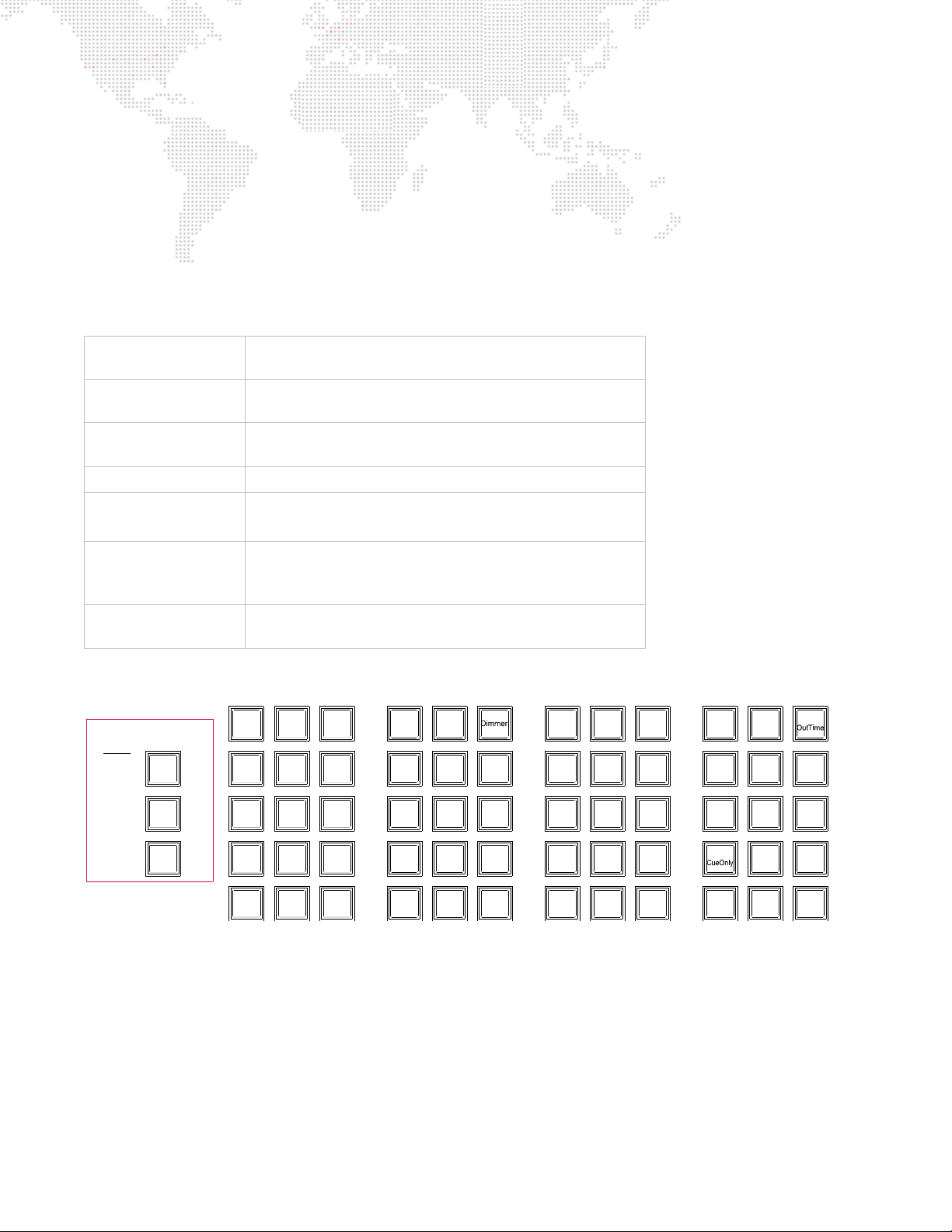
Obtaining Additional DMX Profiles
Shift
Option
Cmd
123
.0
Clear
At EnterFull
789
Time
456
Sub
Rate
Link
+
Thru
-
Loop
Force
Mark
Cue/
Delay/
Speed
Track
Back
Track/
Wait/
Trail
SneakLabel
Move
Delete
Copy/
Sel
Park/
PatchUndoRecall
Store
Unpark
Update
Grab
Help
Query/
Store
Block/
UnBlk
Revert
Manual/
Effect Set Seq
DynamGroup Step
Snap
BeamColorPreset
Macro
Shot
Chan
Cue/
Stack
Board
Cue
WIN =
ALT =
SHIFT =
Mac
Keys
DMX fixtures are controlled by the console using a
profile
. The profile includes the number of DMX channels required
to operate the fixture and parameter mapping for console control. A wide range of profiles are included with the
console software, however, in the event you require additional profiles please send an email to [email protected].
Please be prepared to provide the necessary information to generate the profile as required. (Profiles are covered in
"Updating Profiles" on page 344.)
Text Conventions and Icons
The following button styles are used throughout this manual:
[Button]
<Button>
[Button 1 ] / [Button 2]
[Button/Button] Front Panel button double-click.
Button
Button
Front panel "hard" button.
Example
: Press [Cue] [1] [Enter] to recall Cue 1.
Optional desk button press.
Example
: Press [Store] <Cue> [n] [Enter].
Front Panel button combination sequence.
Press and hold Button 1 while pressing Button 2.
Touchscreen "soft" button.
Example
: Press Plan View to open plan view.
Software menu or window dialog button.
Example
Example
: Click OK.
: At Operation menu, select Luminaire Status.
ENTER
Mac keyboard key.
Example
: Hold down ALT on the Mac keyboard.
Note these equivalent buttons on the Mac keyboard and front panel command-line keypad:
VX76 SOFTWARE USER MANUAL 3
Page 20

Notes
4 VX76 SOFTWARE USER MANUAL
Page 21

1.
GENERAL OPERATION
This chapter provides guidelines for general operation, setting console preferences, and opening a
show file.
+
GENERAL OPERATION
+ SETTING PREFERENCES
+ SHOW FILES
Page 22
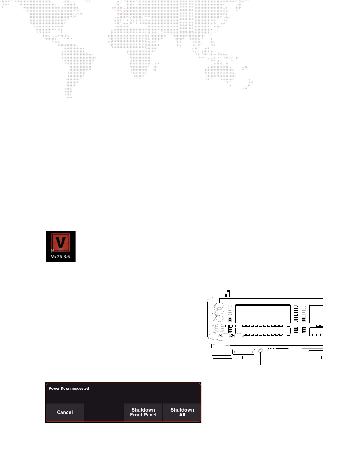
GENERAL OPERATION
V676 Power-Down Button
About Vx76 Software
The Vx76 software application provides the graphical user interface (GUI) for console operation. The Vx76 software is
built on a Mac OS® platform which will be familiar to all windows-based software users.
The Vx76 software provides standard menu-based operations that can be accessed on the external monitor display(s)
by using the cursor or by touching the displays themselves (in the case of touch-enabled monitors). The software also
provides the interface for the touchscreens available on the front panel (desk). In many cases, operations can be done
using either the front panel touchscreens or the menus. This manual covers operations on the front panel
touchscreens, however, these operations could also be done using the menu system. In most cases, the touchscreen
interface and menu-based windows look the same.
The Vx76 software may be upgraded as new features become available.
Power Up Console and Launch Vx76 Application
Use the following procedure to power up the console and Mac computer, and to launch the software application.
To power up and launch:
Step 1. At rear of console, set breaker switch to ON position.
Step 2.
Step 3. At Mac desktop, double-click Vx76 icon to launch application. A new show file (or last open show file) will
V676 console only
initialize.
automatically load and Task Progress window will show progress of data downloads.
: At Mac computer, press power button. Wait for computer to boot up and front panel to
Restart Front Panel (V476/V676 Only)
When the console’s blue power-down button is pressed, a shutdown
dialog will be displayed on the central touchscreen. The dialog
contains two options: 'Shutdown Front Panel’, which independently
powers down the front panel, and 'Shutdown All', which powers
down the front panel and the computer.
To restart front panel:
Step 1. At front of console, press and hold power-down button.
Step 2. At touchscreen, press
Front Panel Shutdown, the blue power-down button will
slowly flash to indicate that it is in sleep mode.)
Step 3. To restart front panel, press power-down button again.
6 VX76 SOFTWARE USER MANUAL
Shutdown Front Panel. (During a
Page 23
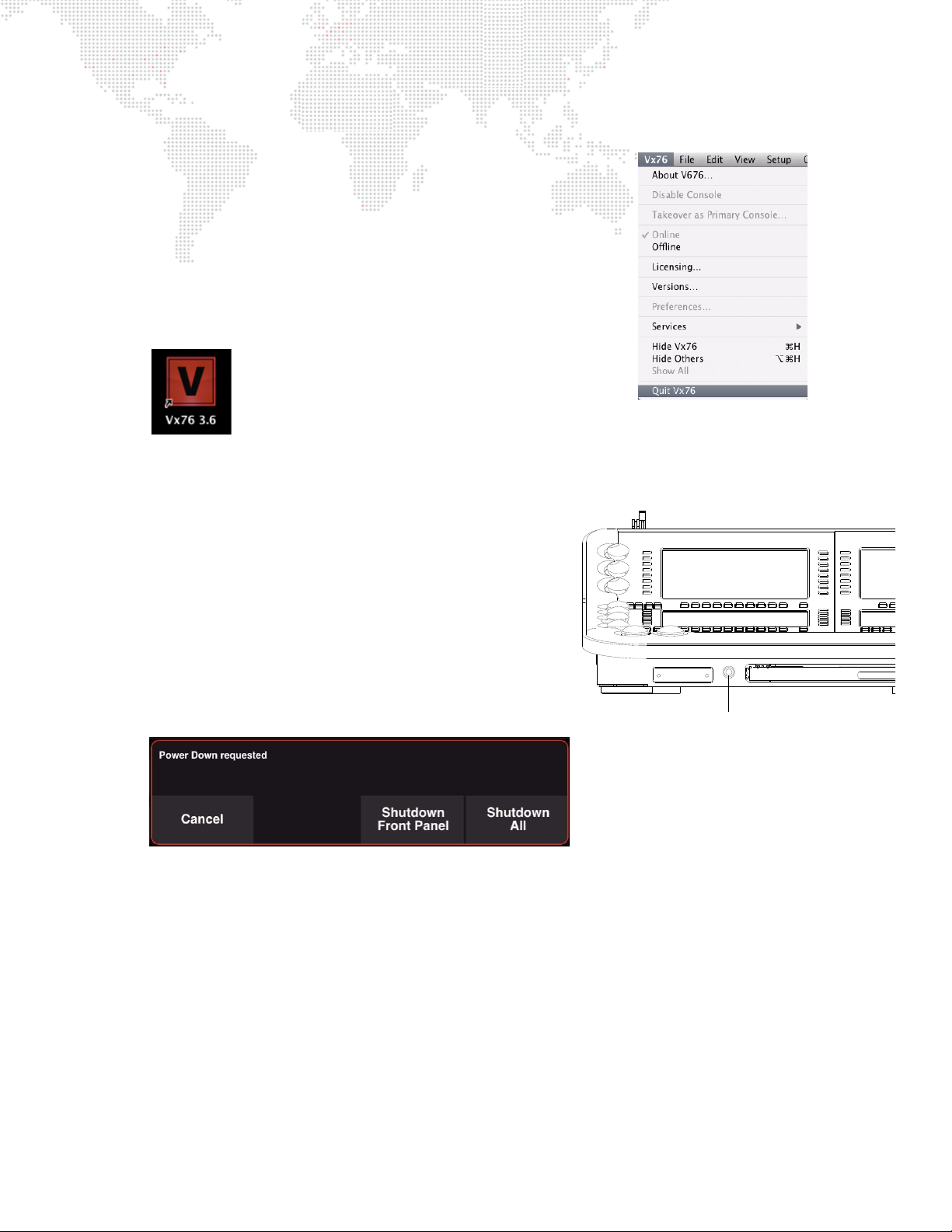
Restart Vx76 Application
V676 Power-Down Button
The Vx76 software application can be independently closed and restarted.
This is useful for upgrading the software or for restarting the application
itself.
To shutdown and restart Vx76 application:
Step 1. At Vx76 menu, select Quit Vx76. Allow application to completely
shut down.
Step 2. At Mac desktop, double-click Vx76 icon to relaunch application.
A new show file (or last open show file) will automatically load and
Task Progress window will show progress of data downloads.
Power Down Console (V476/V676 Only)
When the console’s blue power-down button is pressed, a shutdown
dialog will be displayed on the central touchscreen. The dialog
contains two options: 'Shutdown Front Panel’, which independently
powers down the front panel and 'Shutdown All', which powers
down the front panel and the computer.
To power down console:
Step 1. At front of console, press and hold power-down button.
Step 2. At touchscreen, press
and computer to completely shut down.
Step 3. At rear of console, set breaker switch to OFF position.
Shutdown All. Allow front panel
Power Down Console (V276 On Mac Only)
To power down console:
+ At rear of console, set breaker switch to OFF position.
VX76 SOFTWARE USER MANUAL 7
Page 24
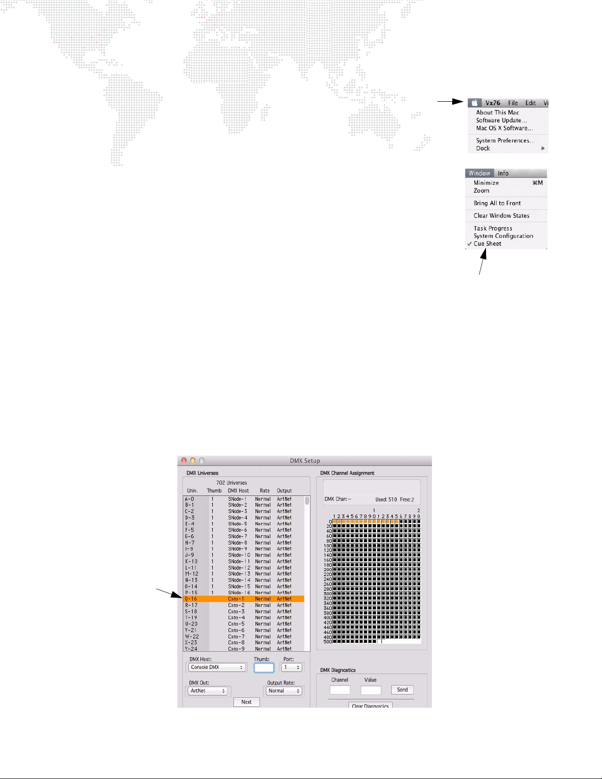
Window Operation
Menu Bar
List of currently
open windows
Use cursor to interface
with the windows
Sample Window
The Vx76 application functions like any standard windows-based computer
software. A menu bar provides access to system windows and controls.
Working with the Windows:
The Window menu offers several functions that assist with locating and sizing
windows:
+ Minimize will minimize the current top window.
+ Zoom will enlarge the current top window.
+ Bring All to Front will bring the Vx76 windows to the top of the Finder.
+ Clear Window States will close and clear all Vx76 windows.
+ A list of currently open windows will appear at the bottom of the Window menu. A dot
will indicate the current top active window (such as Cue Data in the example to the right).
Select the name of any visible window to bring it to the front.
Entering/Editing Window Data:
The computer keyboard can be used to type in alpha-numeric entries or select cells and
fields in the windows.
+ Pressing
+ Pressing
+ Pressing
+ Pressing
+ Pressing
+ Use
The trackpad can be used to manipulate the cursor for field/cell editing, clicking radio buttons, accessing pop-up
menus, moving windows, or closing windows.
ENTER closes the entry field.
ENTER automatically selects the next cell down in the column for editing.
SHIFT + ENTER automatically selects the next cell up in the column for editing.
TAB selects the next cell or field in a row.
SHIFT + TAB selects the previous cell or field in a row.
ARROW buttons to move cursor through fields.
8 VX76 SOFTWARE USER MANUAL
Page 25
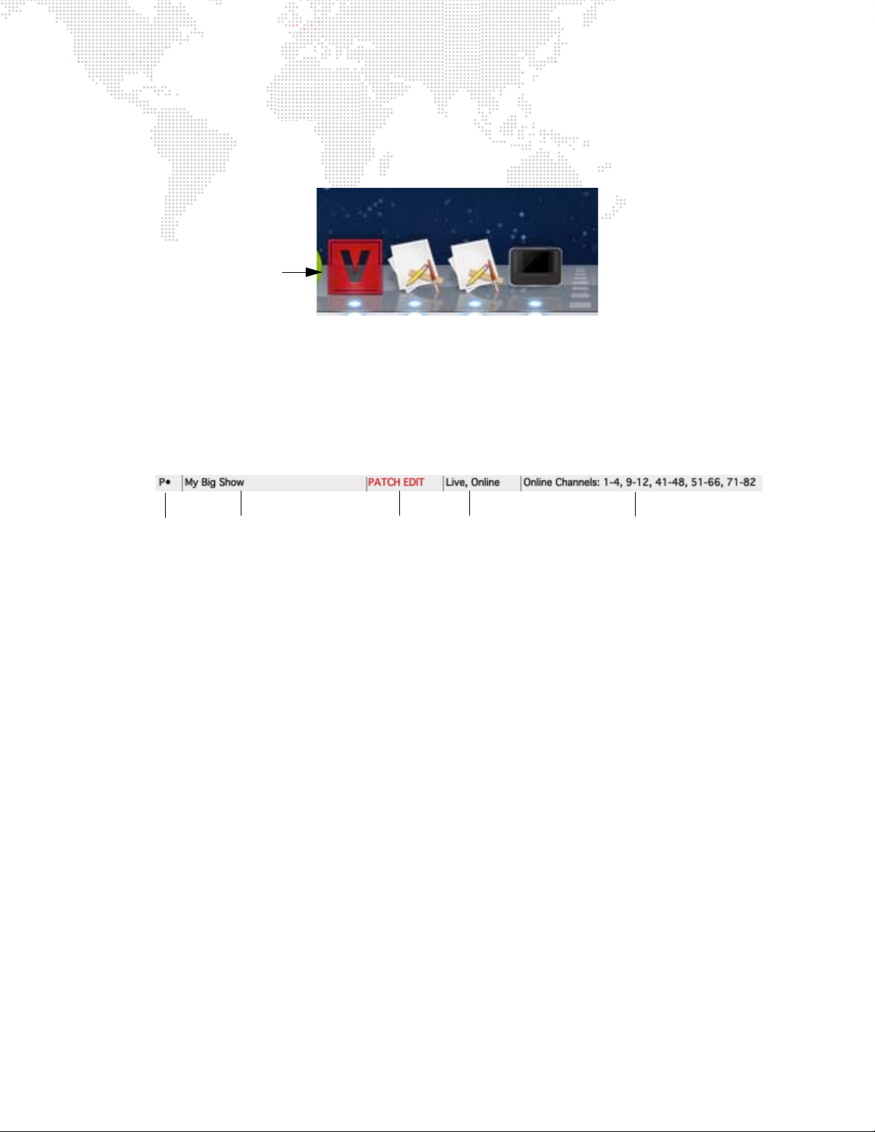
Restoring Vx76 Application:
Vx76 Icon
Live/Preview/Online
Log Messages
Status/State
Showfile Patch Edit
The Mac desktop dock will contain an icon for the Vx76 application once the software is running. To restore Vx76 as
the top application, select its icon from the dock.
Status Indicator Bar
The status bar, located at the bottom of the external monitor display, provides information about current console
status and operations.
Status/State
Indicates the console state or status in relationship to communication between the CPU and Console Interface Card
(CIC). The following indications may be displayed:
+ P - Primary: The console is up and running in the Primary state.
+ PP - Primary Prep: The console is opening a show file.
+ PL - Primary Load: The console is loading data from the show file.
+ PS - Primary Select: The console is waiting on a user selection.
+ U - Unknown: The console is in an unknown state.
+ ** - Error: The console is in an error state due to an internal communication problem.
+ NL - Net Listen: The console is looking for other active consoles on the network.
+ S - Secondary: The console is up and running in the Secondary state.
+ SP - Secondary Prep: The console is synchronizing a show file from the primary.
+ SL - Secondary Load: The console is loading data from the show file.
+ WP - Wait for Primary: The console is waiting for a primary console to be found or selected.
Showfile
Displays the name of the currently open show file.
Patch Edit Enabled/Disabled
"Patch Edit" is displayed when patch is enabled.
The box is blank when patch editing is disabled.
VX76 SOFTWARE USER MANUAL 9
Page 26
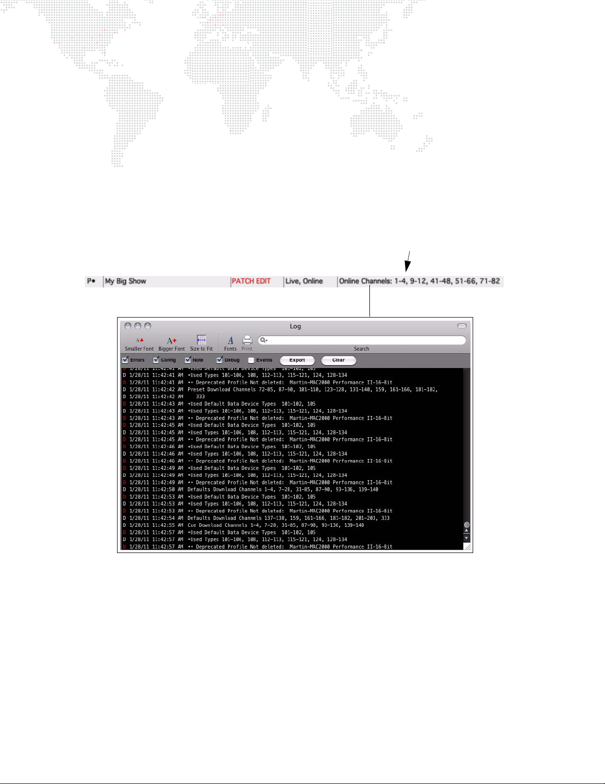
Live/Preview/Off-Line Mode
Log Messages
Indicates whether the console is in the Live, Preview or Off-Line mode.
+ Live Mode - used for live editing. While in Live mode, any manual control actions or event recalls (cues, effects,
dynamic states, etc.) will be executed, in real time, on stage. (Refer to "Live/Preview Mode" on page 329.)
+ Preview Mode - used for preview editing. While in Preview mode, any manual control actions are stored to the
appropriate luminaires, but are not executed on stage. (Refer to "Live/Preview Mode" on page 329.)
+ Off-Line Mode - allows preprogramming without having to connect to a system. (Refer to "Off-Line
Programming" on page 316.)
Log Messages
Messages highlighted in the Log Message box are the same messages collected in the Console Log. Refer to
"Console Log" on page 341.
10 VX76 SOFTWARE USER MANUAL
Page 27
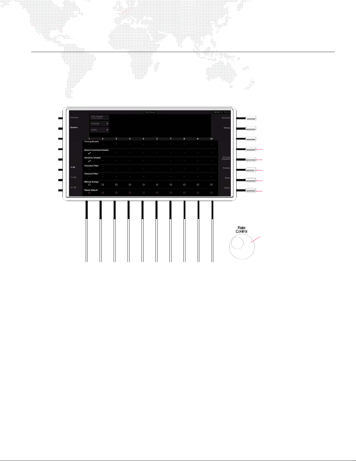
SETTING PREFERENCES
Rate
Encoder
Internal Monitors
Fader Backlights
External Monitors
Backlit Switches
Desk Lamps
Press to dim:
While turning:
Brightness Level (V476/V676 Only)
For Front Panel and Monitors
The brightness level can be set for all monitors, desk lamps, faders, and backlit switches. This is done by pressing the
appropriate button at the Submaster panel while turning the Rate encoder.
Figure 1-1: V476/V676 Submaster Panel
To set a new brightness level:
Step 1. At Submaster panel, press and hold appropriate hard button to activate dimming. Options are:
a. "Blank" button above Timing Disable controls backlit switch dimming level.
b. Timing Disable button controls fader backlights.
c. Freeze button controls desk lamps.
d. Rate button controls external monitors.
e. Clear button controls internal monitors (front panel displays).
Step 2. While holding down button, turn Rate encoder until desired brightness level is reached.
Step 3. Release button. New brightness level will be set.
For Keyboard
The brightness level can be set for the pull-out Mac keyboard.
To set a new brightness level for keyboard:
Step 1. At keyboard, press and hold F
N (function) key.
Step 2. While holding down key, press Up/Down buttons until desired brightness level is reached.
Step 3. Release key. New brightness level will be set.
VX76 SOFTWARE USER MANUAL 11
Page 28
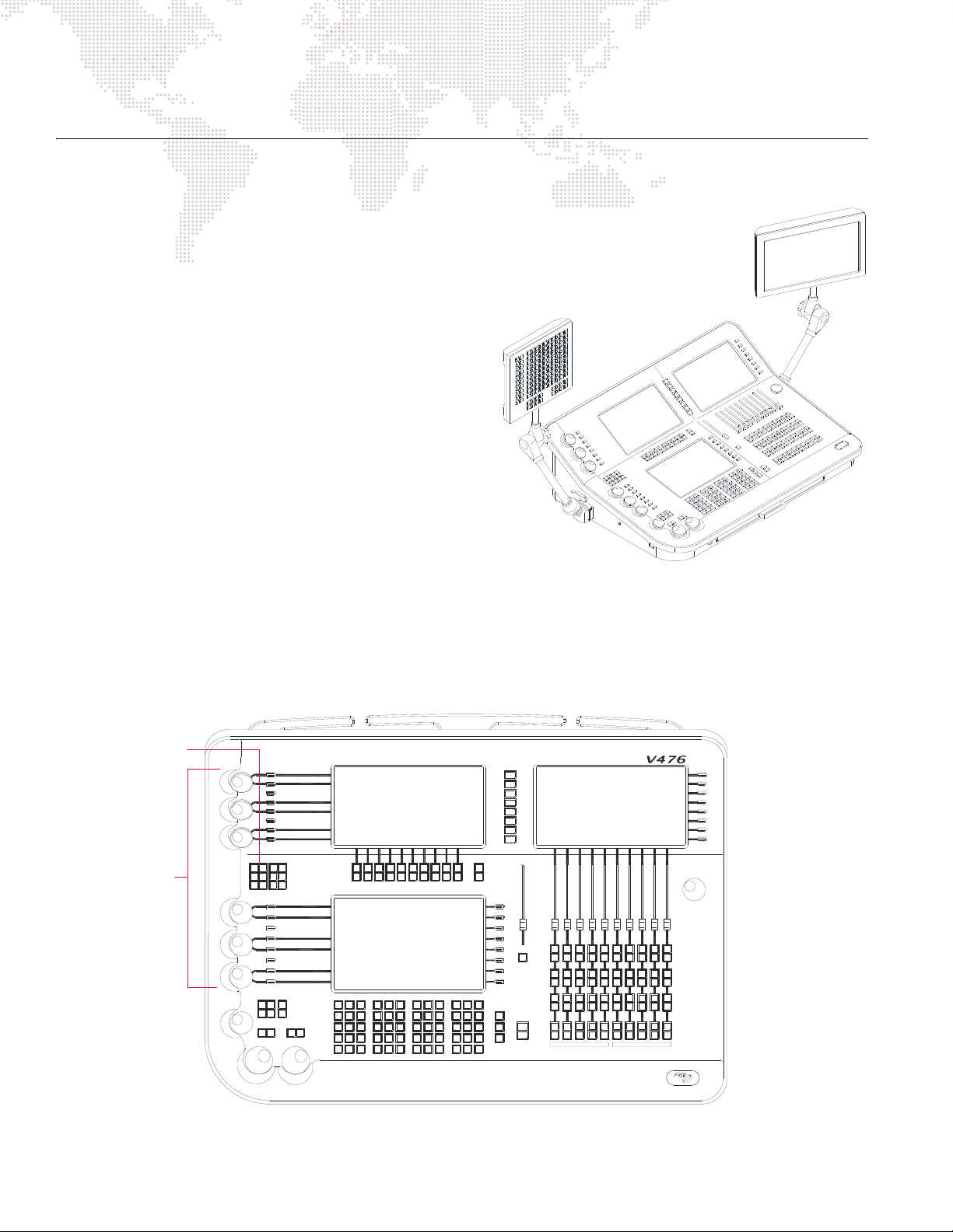
IMPORTANT NOTES REGARDING DIFFERENT TYPES OF VX76 CONSOLES
V476 Control Console
PALETTE
DISPLAY
CENTRAL
DISPLAY
SUBMASTER/UTILITY
DISPLAY
Soft
Encoders
Function
Buttons
Special Features to Accommodate the V476 Front Panel
The V476 console provides the same programming
capacities and capabilities as the V676 console, however,
the desk is smaller and only one external monitor is
provided. Since the same Vx76 software application is
used on both consoles, special features were added with
Vx76 software version 2.5 to accommodate the
differences in hardware.
These special features are as follows:
+ Sliding Encoder Sidebar - The sliding Encoder
Sidebar is used with the six "soft" encoders available
on the V476 desk (Figure 1-2). The V676 has a
designated area for displaying encoder controls, but
since the V476 desk is smaller, these controls are
displayed using the sliding sidebar. The sidebar
appears in the same space as the central and palette
displays when an encoder is turned or an encoder
function button is pressed.
+ Palette Workspace Swapping - The palette
workspace swapping translates the three V676 palette
display spaces to the single V476 palette display.
(Since the three workspaces correspond to the three V676 palette displays, stored snapshots are interoperable
on both consoles.) Refer to "Workspace Swapping" on page 13 for more information.
+ External Display Workspace Swapping - The external display workspace swapping translates the three V676
external display spaces to the single V476 external display. Refer to "Workspace Swapping" on page 13 for more
information.
12 VX76 SOFTWARE USER MANUAL
Figure 1-2: V476 Desk Layout
Page 29
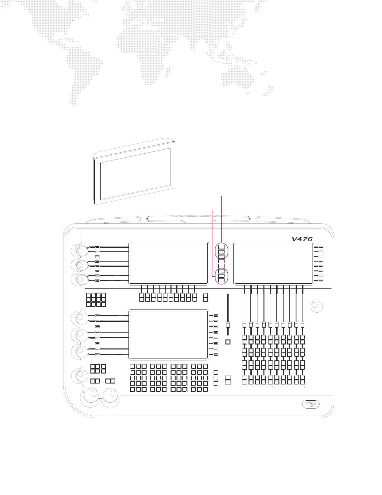
Workspace Swapping
PALETTE
DISPLAY
Palette Buttons
External Display Buttons
EXTERNAL DISPLAY
MONITOR
The V476 palette display space can display one of three different palettes (corresponding to the three palettes
available on the V676 desk). To switch between palettes, press the appropriate button on the right side of the palette
display.
This feature also works on the external display monitor to match the three external monitors available with the V676
console. To switch between monitor display views, press the appropriate button on the right side of the palette
display. (When switching to a different external display view, the windows that are open in that workspace will be
displayed.)
The workspace swapping feature makes it possible to utilize the same stored Snapshot configurations on both
models of console.
Figure 1-3: V476 Desk and Monitor
VX76 SOFTWARE USER MANUAL 13
Page 30
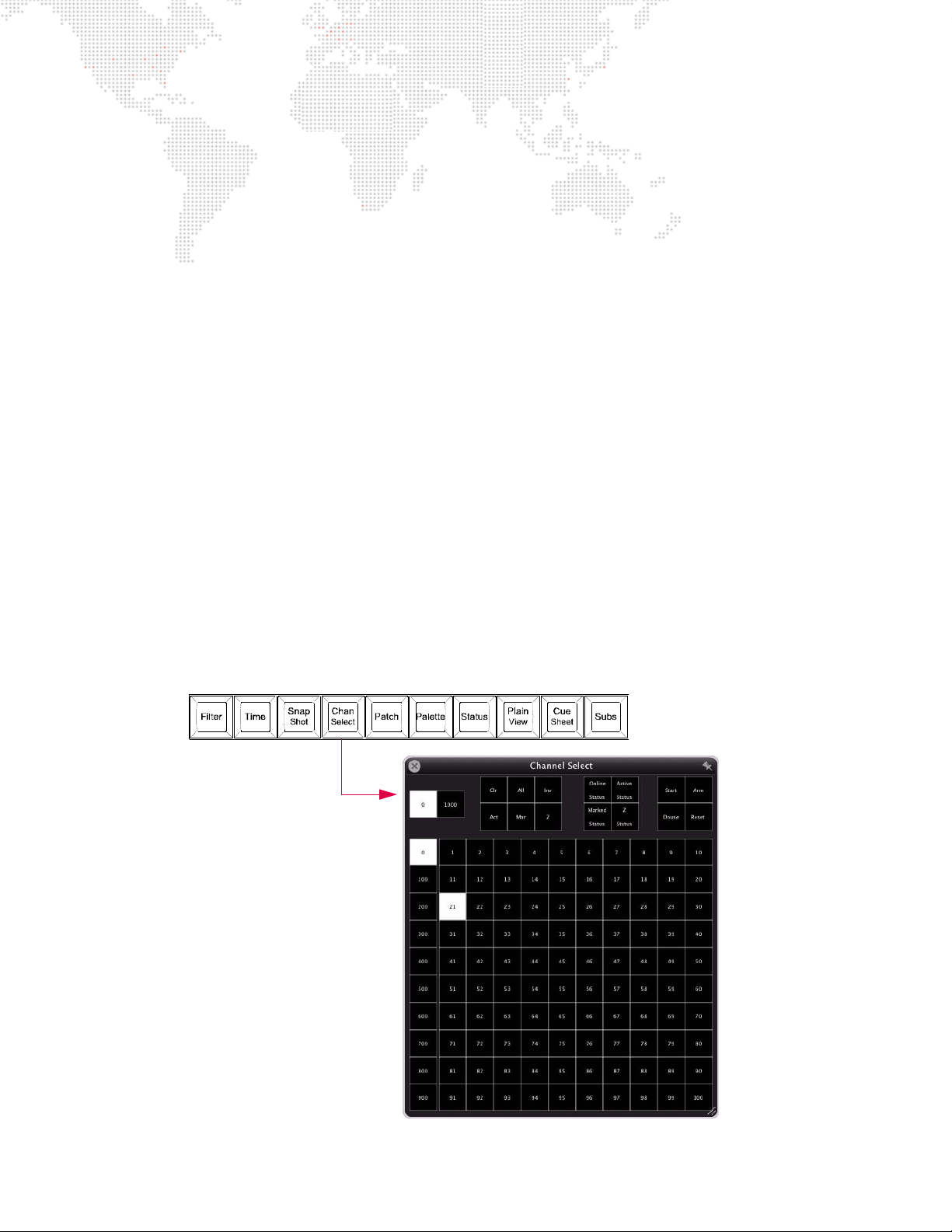
Special Considerations for the V276 On Mac
The V276 On Mac console is considerably different from V476 and V676 consoles in that its front panel does not
contain any touchscreen displays or, in some cases, the same hard buttons. This does not affect its capability to
perform the same functions as the other Vx76 console types, however, in it may be necessary to use various desktop
windows in order to perform the same actions. For example, the V276 front panel does not have a central
touchscreen, but the same command-line data can be displayed and controlled using the V276 HUD window.
Likewise, the V276 On Mac front panel does not contain submaster Run, Stop, or Step buttons, but these can be
controlled using the Submaster HUD window.
In many cases, console operations can be performed at either the front panel using touchscreen displays and hard
buttons, or in the corresponding desktop windows, although this manual typically illustrates one or the other for
clarity. Since the desktop windows look almost identical to the touchscreen displays, it is easy enough to adapt the
instructions to either. In cases where V276 operation is radically different, this will be detailed in the appropriate
section of the manual. If the operations are similar, it may be that examples are shown using only one console’s
particular hardware, however, be aware that the instructions will still apply to your specific console.
The primary areas where the V276 On Mac front panel differs from the other Vx76 consoles are as follows:
+ No front panel touchscreen displays - use equivalent desktop windows such as V276 HUD, Submaster HUD,
Palettes, etc. (Refer to "V276 Display" on page 369.)
+ No dedicated submaster rate encoder - use the virtual Rate knob available on the Submaster HUD. (Refer to
"Submasters HUD Operation" on page 368.)
+ No front panel [Online] button - select Online or Offline from the Vx76 menu or use
Channel Select window.
+ No front panel [Run], [Stop], or [Step] buttons - perform these actions using the Submaster HUD.
+ No front panel [Blackout] button - bring the Grand Master fader to zero.
The V276 On Mac also offers buttons that are only found on this console’s front panel.
+ The first set of buttons are used to open windows on the desktop, such as the Function Filter, Timing Filter, Snap
Shots, or Channel Select. For example, pressing the [Chan Select] button will open the Channel Select window:
Online button available in the
14 VX76 SOFTWARE USER MANUAL
Figure 1-4: V276 Window Buttons
Page 31
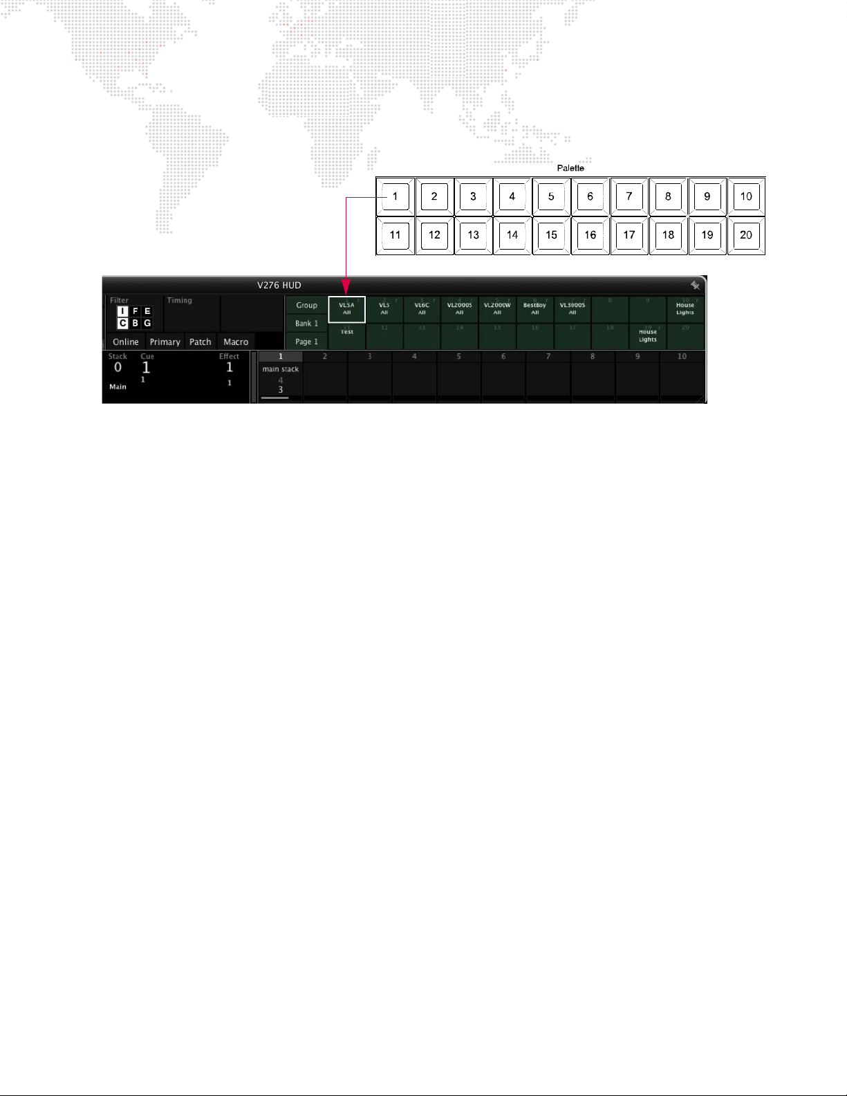
+ The next set of exclusive buttons are used in conjunction with the V276 HUD palette. For example, when the V276
HUD window is open, pressing [1] will select palette entry 1 of the selected page/bank. (Refer to "V276 Display"
on page 369.)
Figure 1-5: V276 Palette Buttons
VX76 SOFTWARE USER MANUAL 15
Page 32
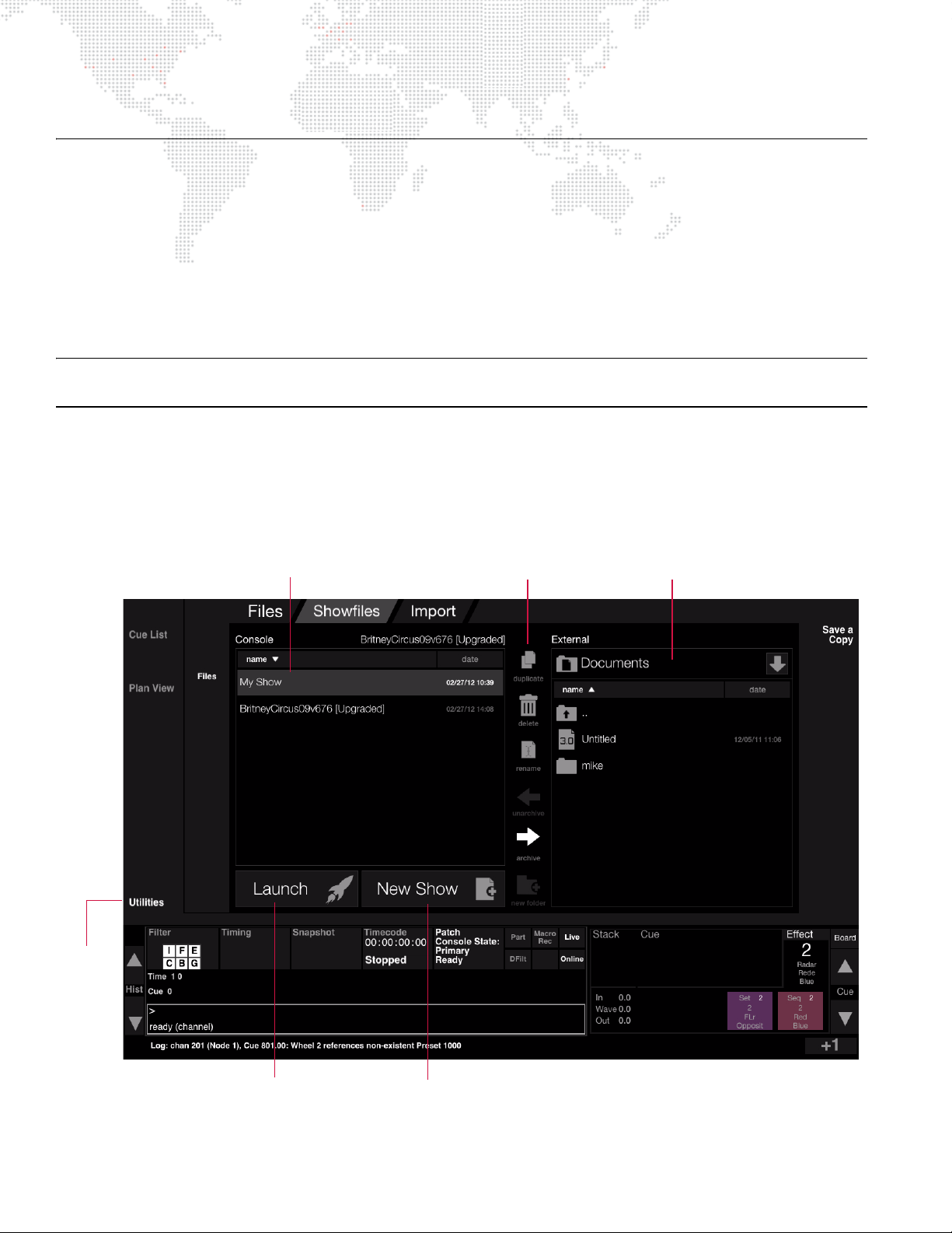
SHOW FILES
Utilities
Button
List of show files in console’s Data Folder External Source Selection Pop-up
Launches selected show file Opens a new show file
File Options
About Show Files
All programming information for a production (i.e., a show) is stored in a
show file
. Show files are made up of
individual data files nested within a show file folder. When the Vx76 software application is launched, it will
automatically open the last show file used on the console, unless one is not available, in which case a new show file is
automatically opened.
Show files can be managed by one of two methods: 1) using the Utilities screen available in the console’s central
touchscreen, or 2) using the Show File Manager window available in the Mac menu bar. These controls allow show
files to be opened, duplicated, renamed, deleted, imported, and/or archived to an external storage device.
Note: This section provides an introductory overview of show files. For more in-depth instructions, refer to the "Show
File and Data Management" on page 332.
Utilities Screen
The central touchscreen Utilities screen is used for show file management. (The functions are the same as the Show
File Manager Mac window.)
+ Press the
Utilities button on the touchscreen to open the show file controls.
16 VX76 SOFTWARE USER MANUAL
Page 33
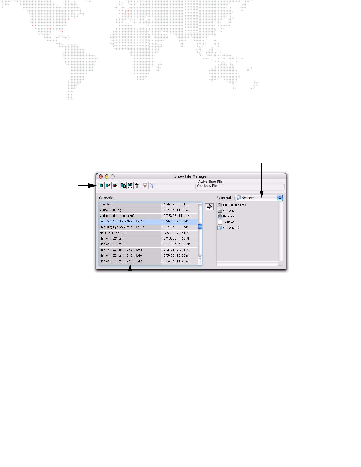
To open a new show file:
List of show files in the console’s Data Folder
Source Selection Pop-up
File options
A new show file can be opened at any time.
+ At Utilities screen, press
New Show button.
To rename, duplicate, or delete a show file:
Only show files resident on the console’s hard drive can be renamed, duplicated, or deleted.
Step 1. At left "Console" showfile list, select show file.
Step 2. Press
Delete, Rename, or Duplicate button as required. (Delete will require a confirmation.)
Show File Manager Window
The Show File Manager software window (available at the File menu) is also used for show file management. (The
functions are the same as the touchscreen Utilities screen.)
VX76 SOFTWARE USER MANUAL 17
Page 34

Notes
18 VX76 SOFTWARE USER MANUAL
Page 35

2.
CONFIGURATION AND PATCH
This chapter provides instructions for configuring the system and patching fixtures.
+
SYSTEM CONFIGURATION
+ PATCH
+ PLAN VIEW
Page 36
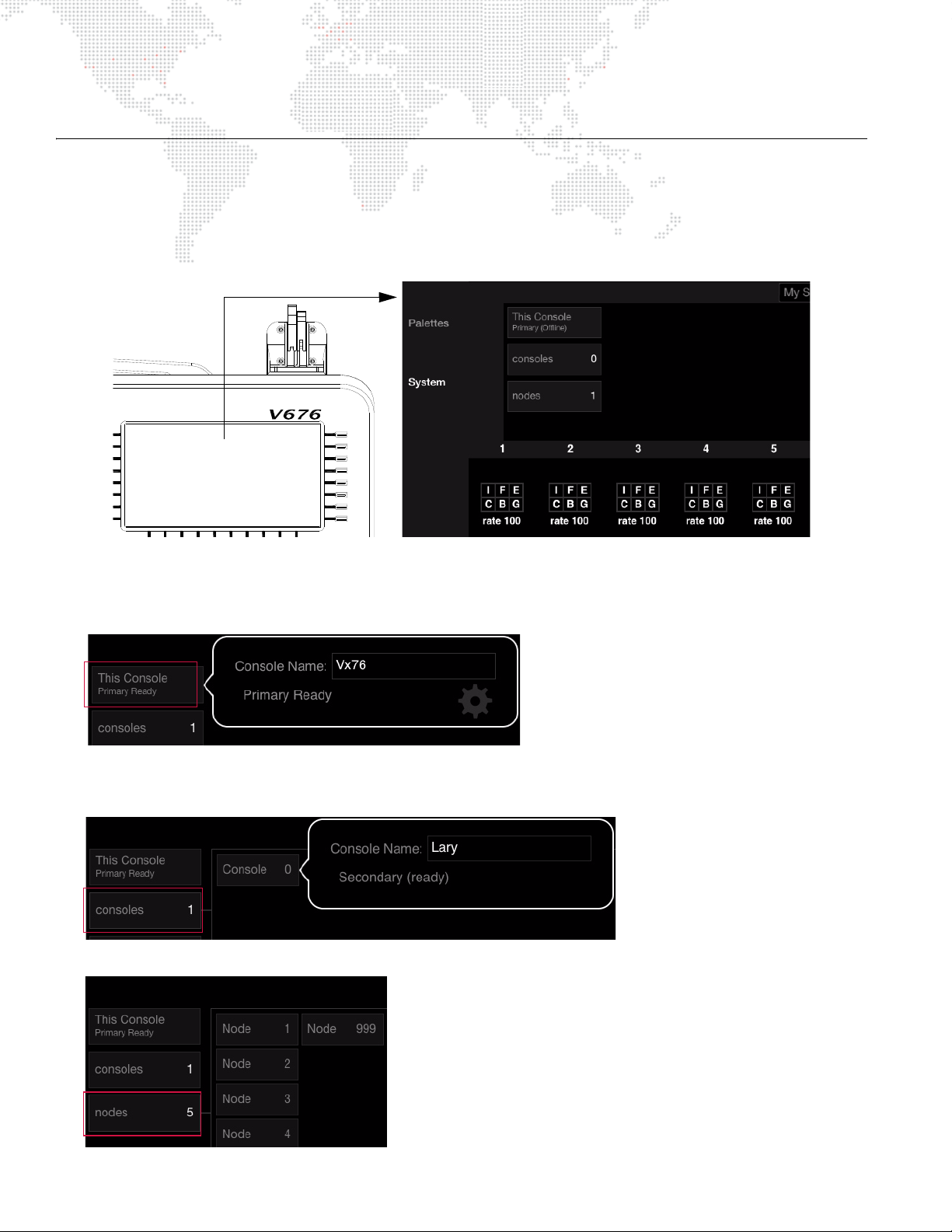
SYSTEM CONFIGURATION
System Configuration Overview
The system configuration tools provide details and configuration options for the console and system devices. The
configuration can be stored for future reference using the Store/Clear actions.
Note that the
The main configuration screen allows access to the following items:
+ Console Name and Details - Pressing This Console will display the console’s primary/secondary status and
online/off-line status.
System button must be pressed to view the system info. Pressing Palettes will display a palette.
+ Other Consoles - Pressing
connected to the system.
+ Nodes - Pressing
20 VX76 SOFTWARE USER MANUAL
Nodes will display all connected Node devices.
Other Consoles will display information about other consoles that may be
Page 37
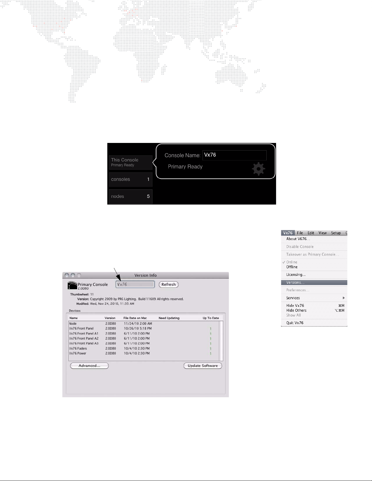
Using System Configuration
Type name for console
Naming a Console
The console naming feature is useful to identify each console when two or more consoles are connected to a single
system. For example, you could name the consoles "Main" and "Backup." (Also refer to "Setting Up Backup
(Secondary) Consoles" on page 313). The console name can be set or changed at any time using the System
Configuration screen or Version Info window.
To name a console using System Configuration:
Step 1. Press
Step 2. Touch Console Name field.
Step 3. Enter name. For example, "Vx76" as shown below.
To name a console using Version Info window:
Step 1. At Vx76 menu, select Versions .
Step 2. At name field, type a console name.
Step 3. Close window.
This Console.
VX76 SOFTWARE USER MANUAL 21
Page 38
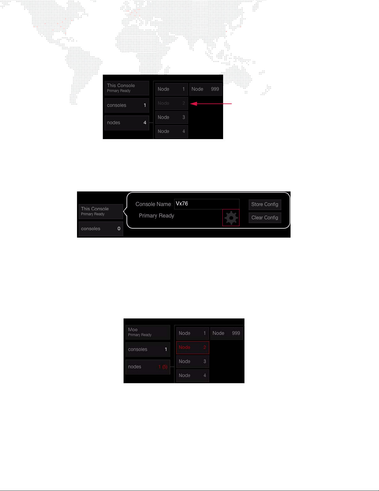
Store/Clear Configuration
Missing Node
Your system setup can be stored for future reference. After the configuration is stored, if a device is not online when
the system is powered up, the missing device will be indicated in a darker gray color.
To store system configuration:
Step 1. Press
Step 2. Press gear icon to bring up Store and Clear options.
Step 3. Press
This Console.
Store Config.
To clear stored configuration:
Step 1. Press
Step 2. Press gear icon to bring up Store and Clear options.
Step 3. Press
This Console.
Clear Config.
Error Messages
If the console detects an error with a connected device, this will be indicated in red.
22 VX76 SOFTWARE USER MANUAL
Page 39
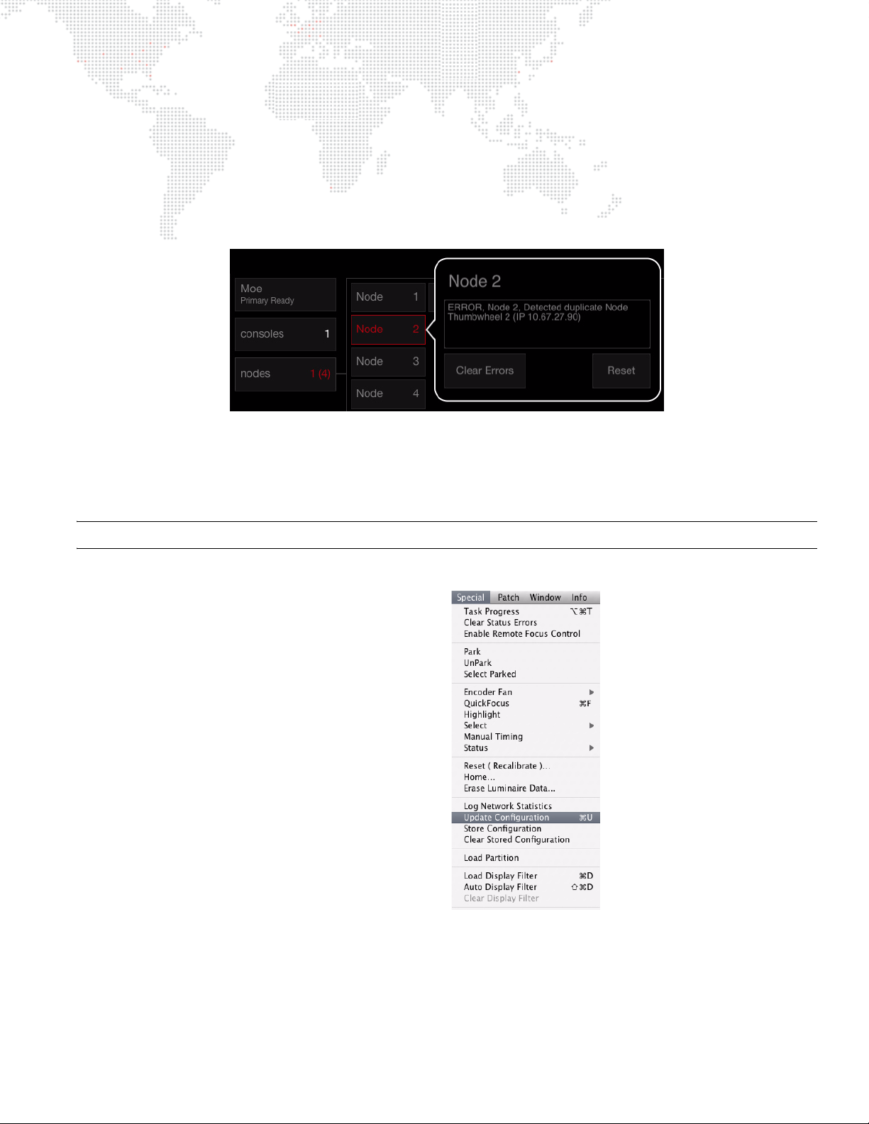
Clear Errors / Reset Node
Nodes can be reset from the System Configuration screen.
To clear or reset node:
Step 1. Press
Step 2. Press button of required Node.
Step 3. Press
nodes.
Clear Errors and/or Reset as required.
Update Configuration
In the event a new device(s) is added to your system while the console is powered up, the system can be repolled so
that the new device(s) will appear in the System Configuration window.
Note: This is not related to the Stored Configuration.
To update a configuration:
+ At Special menu, select Update Configuration.
VX76 SOFTWARE USER MANUAL 23
Page 40
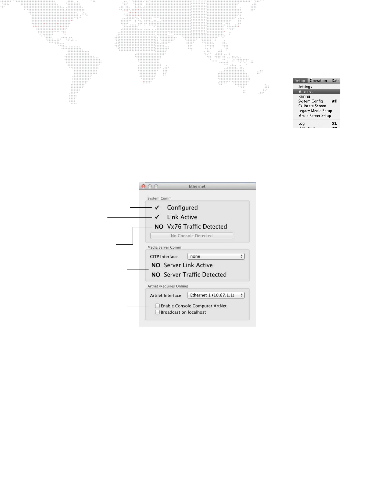
Ethernet Configuration
Indicates that the network
device configuration is valid.
Indicates that there is an
active link on the port.
Indicates whether system
traffic has been seen on the
port.
Media Server CITP Info
Art-Net Interface Info
The Ethernet settings for properly prepped consoles should be suitable for operation and will not require any
configuration. However, if improper settings are detected, the Ethernet window can be used to resolve errors.
To view/change settings:
+ At Setup menu, select Ethernet.
The Ethernet window displays the current status of the Ethernet network, and offers a
method for auto-configuration in the event there is a problem.
The Vx76 control network is designed to work on the 10.67.x.x subnet. One of the
computer's built-in ports should be configured to an address in this subnet. If the software cannot find an active port
set to that subnet, then an error message will be displayed on the front panel, and the Ethernet dialog will be
displayed. If the problem is the port configuration, the Auto-Configure button will modify the network settings
accordingly. If this does not work, check the physical connections to the back of the computer, or replace the
Ethernet/USB cable to the front panel.
24 VX76 SOFTWARE USER MANUAL
Page 41
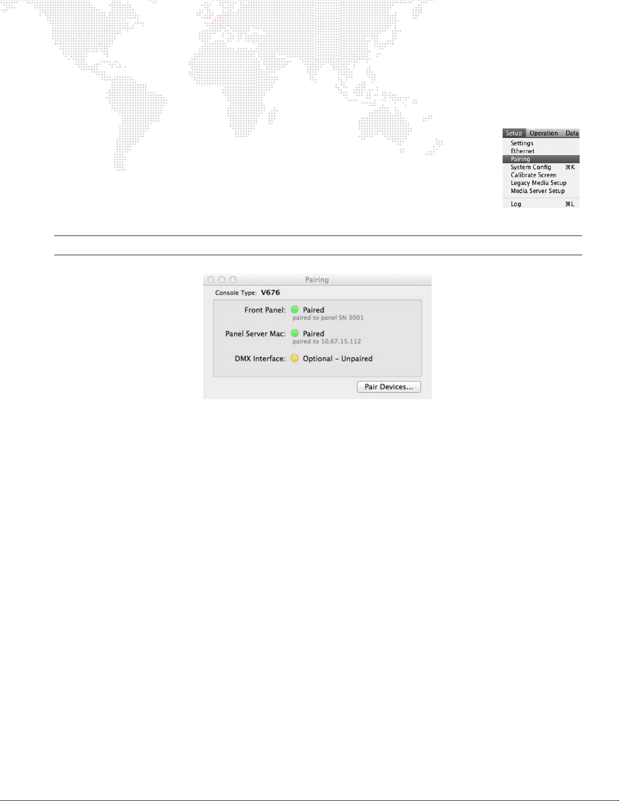
Device Pairing
For proper operation, the software must pair with different pieces of hardware within the console. This process is
completed during the console's installation, but may need to be paired again if internal devices are changed.
Pairing console devices can be accomplished as follows:
Step 1. At Setup menu, select Pairing. (Pairing window will open.)
Step 2. Click Pair Devices button.
Step 3. Disconnect external system networking (Ethernet and/or fiber) from back of
console and press Scan to continue.
Step 4. Once all devices have been discovered, click Pair to complete the pairing
process.
Note: Some devices, such as the Vx76 DMX Interface, are optional, and may not be installed on the console.
VX76 SOFTWARE USER MANUAL 25
Page 42
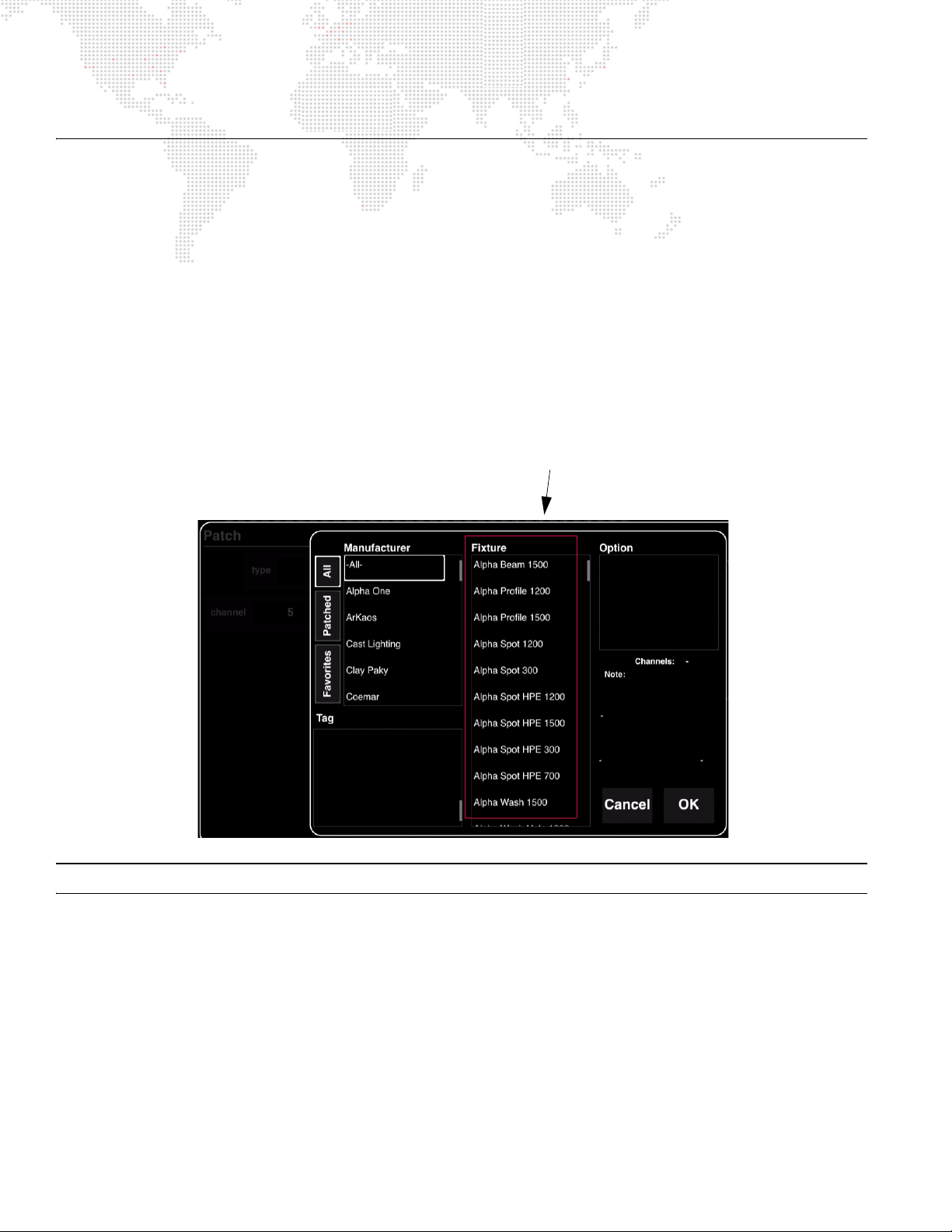
PATCH
Profiles
Patch Overview
Patching is the simplest way to manage the fixtures connected to the console. Patch associates a single control
channel with a single fixture so that you can select one channel at the console and have control of all the fixture’s
parameters (intensity, color, beam, etc.). The patch operates by creating a look-up table that the console uses to
translate a fixture’s associated DMX address(es) into a single control channel.
Patching can be done via the command line or Plan View.
Profiles
DMX fixtures must be patched to the console using a
of DMX512 channels required to operate the fixture and all parameter mapping necessary for control by the console.
Profiles are stored in a Vx76 system folder which is accessed each time a new show file is opened.
profile
in order to be controlled. The profile includes the number
Note: Also refer to "Updating Profiles" on page 344.
26 VX76 SOFTWARE USER MANUAL
Page 43
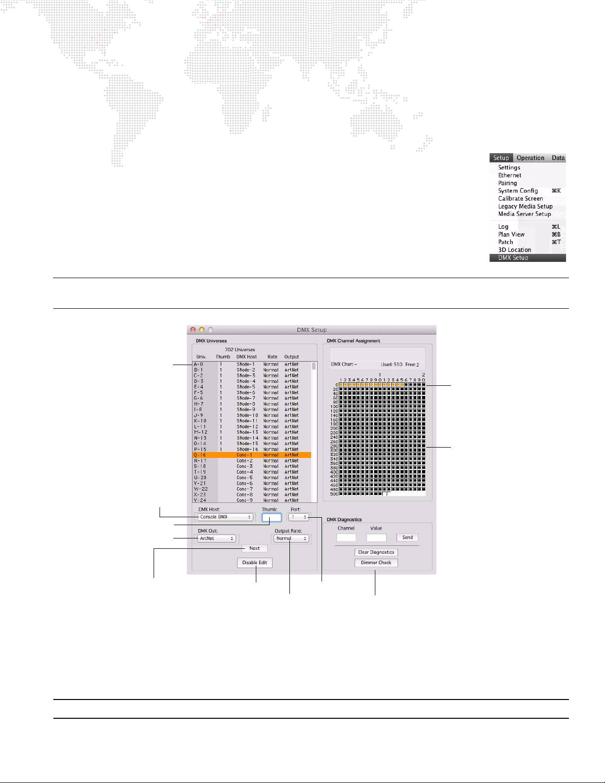
DMX Universes
Node Address
Advance Button Press to enter current settings
and advance to the next line
Enable/Disable
DMX Output of Node
DMX Universe (A-ZZ)
Must be assigned to a
DMX Host (Node, etc.)
DMX512 channel
assignments for
selected universe
Orange highlights
show DMX channel
range for selected
fixtures
Patch Editing
DMX
Output Rate
Port #
Host Device
For use with DMX Diagnostics feature *
The console provides for a maximum of 702 universes (labeled A thru ZZ), which are assigned to DMX buses or
"hosts" (hardware outputs within the system). This means that the actual amount of buses available will depend on
your system setup.
To define DMX512 universes:
Step 1. At Setup menu, select DMX Setup. (DMX Setup window will open.
Step 2. Select desired DMX Universe.
Step 3. Enable Patch Edit by pressing Patch Edit button at bottom of window.
Step 4. Select "Super Node" from DMX Host menu.
Step 5. Enter Node thumbwheel address in "Thumb" field.
Step 6. Choose "Port" output.
Step 7. If assigning multiple universes, click Next or press [Enter] to edit the next
universe. Otherwise, select Disable Edit to disable patch edit and save changes.
Note: If patching sequential Nodes and outputs, pressing the [Return] button on the keyboard will auto increment the
patch. If not sequential, repeat Steps 4 through 6.
)
Streaming ACN
Each PRG Node Plus output port can be configured to send ANSI E1.31 Streaming ACN (sACN) format packets over
the Ethernet port instead of Art-Net packets. This selection is made by setting the DMX Out option to "sACN" and
clicking the Set button. (The default output type is Art-Net.)
Note: E1.31 does not allow universe 0, so that universe cannot be used with sACN.
* For instructions on using DMX diagnostics, refer to "DMX512 Channel Tests" on page 348.
VX76 SOFTWARE USER MANUAL 27
Page 44
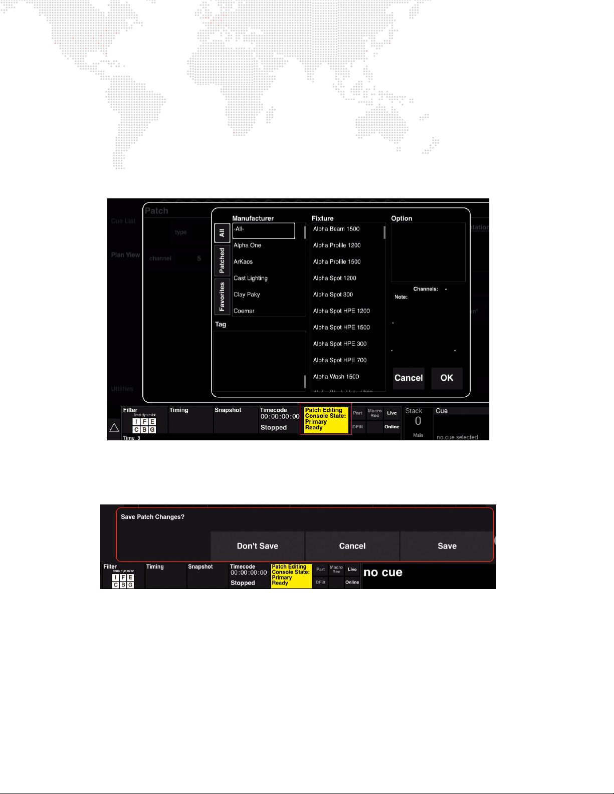
Patch Procedures
Luminaire patching can be done using the command-line keypad and central touchscreen. (It can also be done using
the Plan View, however, this is covered in "Plan View Layouts" on page 41.)
Enabling/Disabling Patch Editing
To enable patch editing:
+ Press the
editing mode is active.)
Patch button on the touchscreen. (It will be highlighted in yellow and display "Patch Editing" when the
To exit patch editing (disable):
+ To exit patch editing, press the
changes, or return to editing (cancel).
Patch Editing button. A confirmation dialog will allow you to save or discard
28 VX76 SOFTWARE USER MANUAL
Page 45
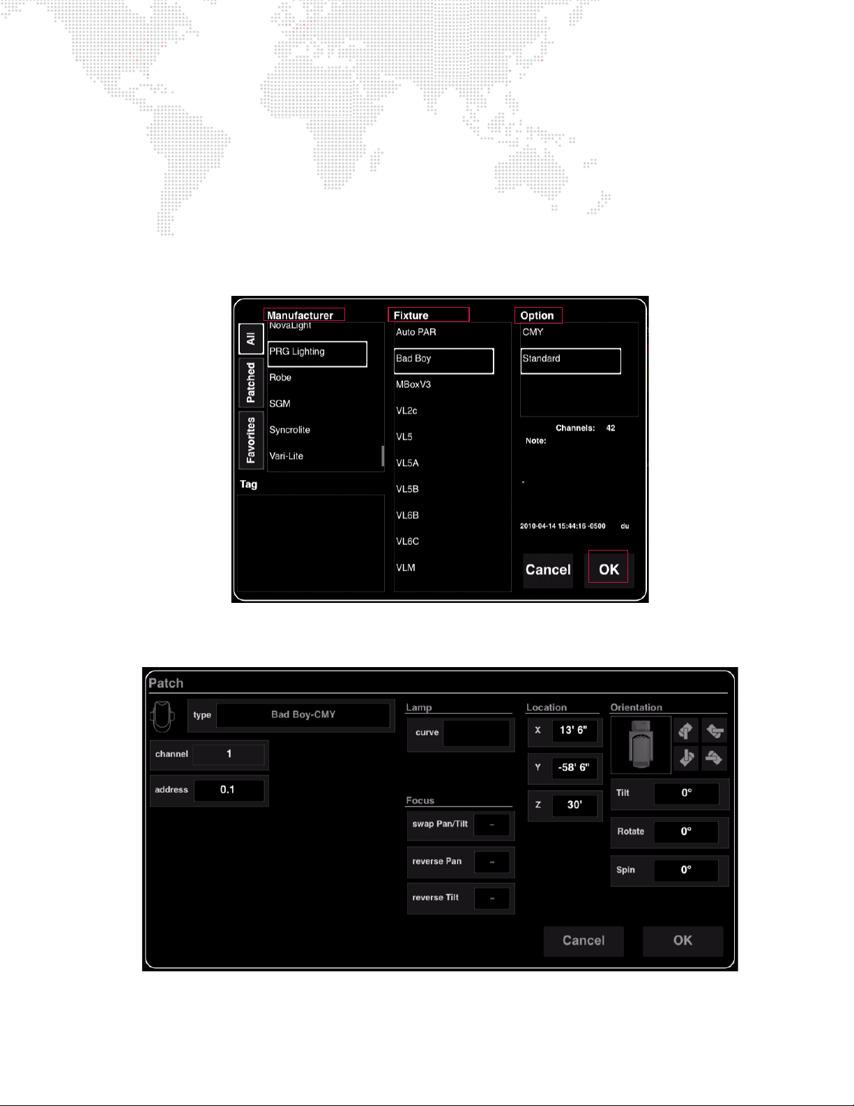
Patching DMX Fixtures
The patch setup screens will be slightly different depending on whether a DMX fixture or conventional fixture is being
patched.
To patch a DMX fixture:
Step 1. At command-line keypad, press [Patch] button. Patch dialog will open in central touchscreen and Patch
Editing mode will be enabled.
Step 2. First select a Manufacturer, then the Fixture type, then an Option (if applicable - not all fixtures will have
options).
Step 3. Press
OK to go to next setup screen.
Step 4. At fixture Patch screen, set options as required. Touch in field (such as channel number) and use keyboard
to enter values, or use command-line entries.
VX76 SOFTWARE USER MANUAL 29
Page 46
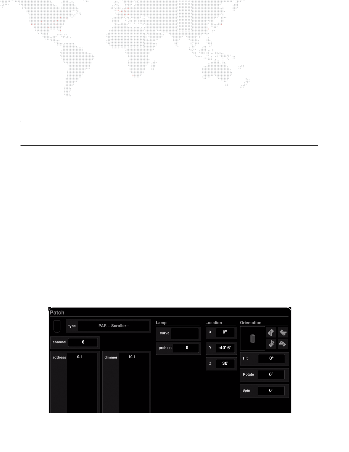
+ Channel - fixture’s channel number.
+ Address - fixture’s DMX universe/address. The DMX universe and address is expressed with dot notation, for
example, the first address of universe 0 (A) would be 0.1.
+ Lamp Curve - specifies lamp dimmer curve setting (if applicable): Fast Bottom, Fast Top, Full at 1%, Hot Patch,
IES Square Law, Slow Bottom, or Slow Top.
+ Focus - options for swapping and/or reversing pan and tilt.
+ Location - for use with 3D graphic features. Refer to "X, Y, Z Locations" on page 323.
+ Orientation - for use with 3D graphic features. Refer to "3D Orientation" on page 324.
+ DMX Offset - sets DMX offset channels between fixtures.
Note: When entering the universe/address, a decimal point must ALWAYS be used even if only one value is provided.
For example if entering both values, the entry would be [
would be [
universe#
.]. If entering only the address, the entry would be [.
universe#.address#
address#
]. If entering only the universe, the entry
].
Entering Patch Commands
A patch command has the following format:
+ [Patch] [Chan] channel# [At] universe#.address#
If the channel number or DMX address is not included, the luminaire will be patched at the next channel or address.
For example, to patch a luminaire at channel 10 as the first channel in DMX universe 2, enter the following command:
+ [Patch] [Chan] 10 [At] 2.1 [Enter]
A [Patch] [Enter] immediately after this will patch channel 11 with the same luminaire type at the next available DMX
address in universe 2 (as long as channel 11 does not already exist).
Remember to change the luminaire type if necessary before pressing [Enter].
Luminaires are automatically located in the Plan View. The luminaire icons can be moved in the Plan View display
while patch edit is enabled.
Patching a range of luminaires can be accomplished with the following syntax:
+ [Patch] [Chan] start# [Thru] end# [At] universe#.address#
Patching Multi-Channels - Conventionals and Scrollers
Conventionals and scrollers can be patched to multiple DMX channels:
+ [Patch] [Chan] chan# [At] universe#.address# [Thru] address# + address#
30 VX76 SOFTWARE USER MANUAL
Page 47

For example, to patch a conventional at channel 20, mapped to DMX universe 4, addresses 1-10, 12, and 15:
+ [Patch] [Chan] 20 [At] 4.1 [Thru] 10 [+] 12 [+] 15 [Enter]
Scrollers are patched in a similar way, but the [Dimmer] key is used to specify where the intensity channels are
patched. For example, to patch a scroller at channel 30, mapped to DMX universe 5, channels 1-5, with intensity on
DMX universe 6, channels 1-5:
+ [Patch] [Chan] 30 [At] 5.1 [Thru] 5 [Dimmer] 6.1 [Thru] 5 [Enter]
Five scroller type choices are provided in order to allow different scrollers to reference different gel strings.
+ Scrollers 1-4 - Four additional generic scroller types.
Note: Scroller color control is controlled by the Wheel encoder.
To delete a DMX channel from conventional channels:
+ [Patch] [Chan] chan# [At] [-] universe#.address# [Enter]
+ [Patch] [Chan] chan# [At] [-] universe#.address# [Thru] address# [Enter]
LED Fixture Control
The console supports LED fixtures where the light output is a function of 3-5 color channels, and no direct intensity
control is provided. This type of fixture is controlled as follows:
+ The intensity control acts as a "master" of the color channels. If the intensity level is set at 50%, all color outputs
will be reduced by 50%. This also applies to submaster and grandmaster control of intensity, i.e., the Blackout
function will cause LED fixtures to go out.
This mode is enabled via a flag in the DMX fixture profile. (Refer to "Profiles" on page 26.)
Patching Ranges
It is possible to span to next universe when range patching new fixtures. The DMX start addresses will continue on to
the next universe, until another patched channel is encountered.
VX76 SOFTWARE USER MANUAL 31
Page 48

Patch Editing
Patch editing can be done using the command line or the Patch spreadsheet window.
Important! When entering the universe/address, a decimal point must ALWAYS be used even if only one value is
provided. For example if entering both values, the entry would be [
the entry would be [
universe#
.]. If entering only the address, the entry would be [.
Using Command Line
To edit a patched channel:
To edit a previously patched channel, enter [Patch] chan# to bring up the patch dialog for that channel. Here the
luminaire type can be changed or patch options edited. The DMX address can also be changed using the usual [At]
syntax.
You can also change the universe assignment for multiple luminaires with one command. For example, to move
patched luminaires 1-14 to universe 20:
+ [Patch] [Chan] 1 [Thru] 14 [At] 20 [.]
To delete a patched channel:
To delete a channel from the patch:
+ [Patch] [Delete] [Chan] # [Enter]
To move patched channels:
To move patched channels to a different channel:
+ [Patch] [Move] [Chan] # [Thru] # [At] # [Enter]
To delete a DMX channel from conventional channels:
+ [Patch] [Chan] chan# [At] [-] universe#.address# [Enter]
+ [Patch] [Chan] chan# [At] [-] universe#.address# [Thru] address# [Enter]
universe#.address#
address#
]. If entering only the universe,
].
Using Patch Spreadsheet
The Patch window displays patch information in a spreadsheet format. Data can be viewed at any time and edited
when patch editing is enabled. Refer to "Patch Spreadsheet" on page 33 for more information about this window.
Using Plan View
With Patch enabled, double-click a fixture to bring up the edit dialog. Refer to "Plan View" on page 37 for more
information about the Plan View.
32 VX76 SOFTWARE USER MANUAL
Page 49
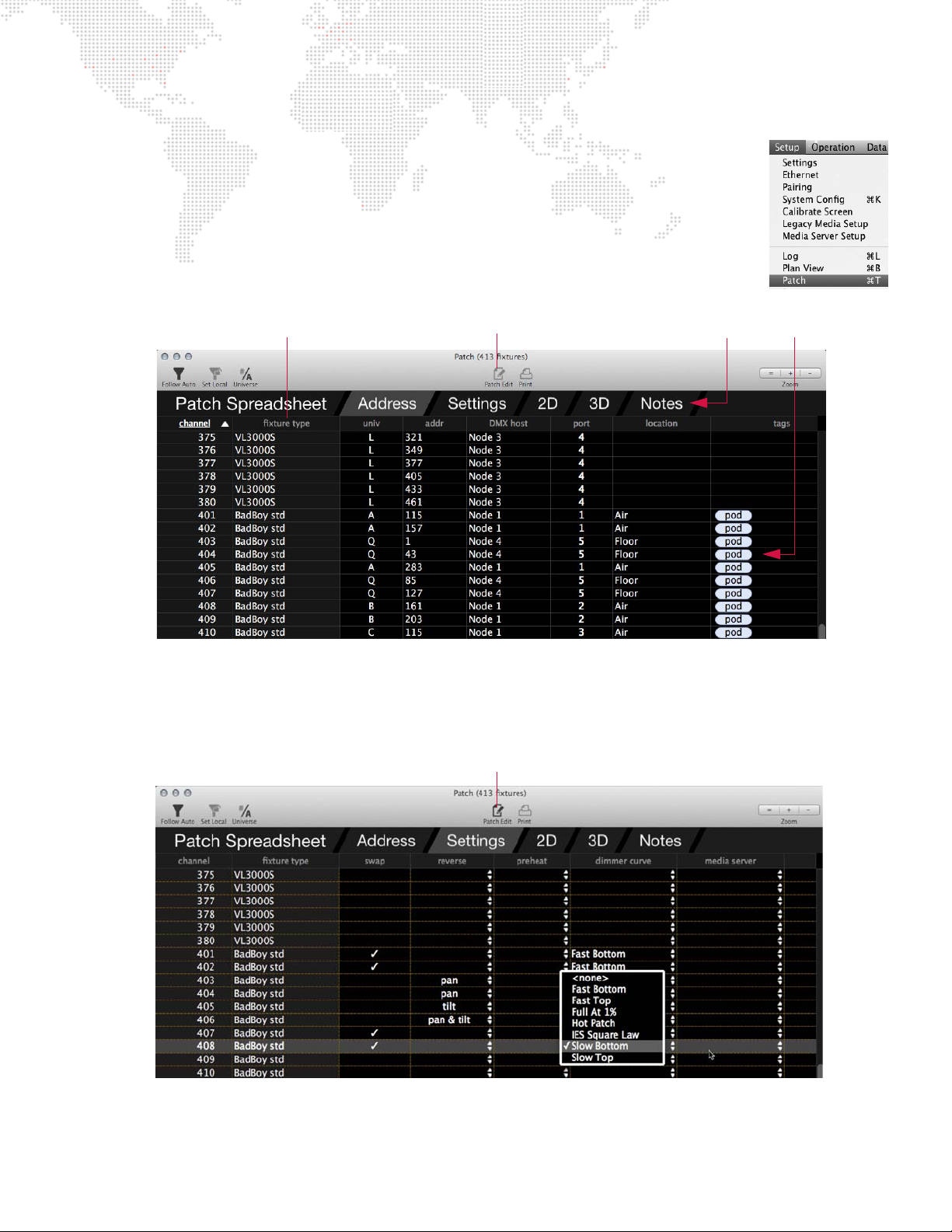
Patch Spreadsheet
Tags
Click column heading to sort
by specific information type
Tabs
Patch Mode Indicator (disabled)
Patch Mode Indicator (enabled)
The Patch window displays patch information in a spreadsheet format. Data can be viewed in
different categories using the various tabs located at the top of the window. The data can be
edited while in the Patch Edit mode.
To open the Patch window, select Patch from the Setup menu.
+ Address - The Address tab displays the data by address. A Tags column allows
information to be added to each channel that can be used elsewhere in the console. (This
can be useful to label floor lights, specials, etc.)
+ Settings - The Settings tab displays settings such as swap, reverse, preheat, and dimmer curve. It also indicates
which fixtures are assigned to specific media servers. (This is useful with the Media palette features. Refer to
"Controlling Media Servers" on page 210.) When editing, some cells offer a pop-up menu, such as Dimmer Curve
shown below.
+ 2D/3D - The 2D and 3D tabs display the 2D/3D coordinate data.
+ Notes - The Notes tab displays any notations that may have been added to the fixtures.
VX76 SOFTWARE USER MANUAL 33
Page 50
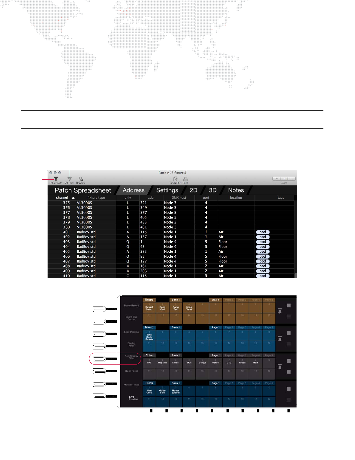
View Filtering
Follow Auto
Set Local
Filter Button
Filter Button
Auto Display Filter
Toggle Button
Two filtering options are available using the "Follow Auto" and "Set Local" filter buttons at the top of the window.
+ Follow Auto - filters the view to the Auto Display Filter, if it is enabled. In other words, if the Follow Auto button is
enabled in the patch spreadsheet, and the Auto Display Filter is enabled, the patch spreadsheet will only show
channels that are selected on the console.
+ Set Local - sets any current channel selection as a local view filter. In other words, whatever channels are
currently selected will be the only channels shown in the window until the local filter is cleared.
- To clear the local channel filter, clear the channel selection and click the Set Local button.
Note: The Auto and Local channel filters can work together to help filter the view based on a specific local filter and
your selected auto filter.
34 VX76 SOFTWARE USER MANUAL
Page 51
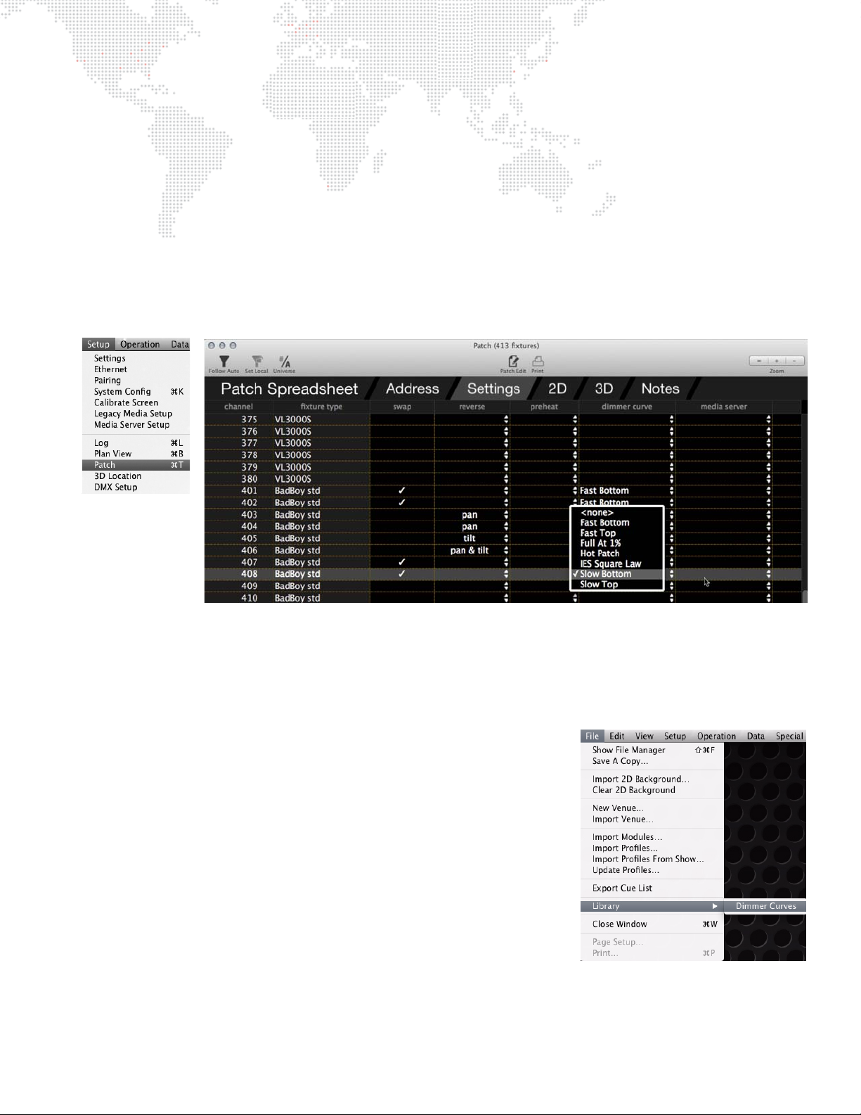
Dimmer Curves
Overview
Dimmer curves provide better control of luminaire lamps. There are seven pre-programmed dimmer curves available:
Fast Bottom, Fast Top, Full at 1%, Hot Patch, IES Square Law, Slow Bottom, and Slow Top.
To set dimmer curve from Patch window:
Step 1. At Setup menu, select Patch. Window will open.
Step 2. Enable patch by pressing
Editing" when the editing mode is active.)
Step 3. For desired luminaire, click in Dimmer Curve column.
Step 4. At drop-down menu, select dimmer curve configuration.
Patch button on touchscreen. (It will be highlighted in yellow and display "Patch
Dimmer Curves Window
The Dimmer Curves window allows import, export, updating, and deleting of dimmer curves. Dates of dimmer curve
files are shown for the console and for the show file. They may be copied easily from the show file to the console, or
from the console to the show file.
To open Dimmer Curves window:
Step 1. Select Library/Dimmer Curves from the File menu.
To move dimmer curve files:
Step 1. At Dimmer Curve window, using trackpad, select dimmer curve to
be moved.
Step 2. Click on Copy Direction column between Console and Show File
column. This column will change from a Bullet, to left arrow, or a
right arrow. Keep clicking until desired direction is displayed.
VX76 SOFTWARE USER MANUAL 35
Page 52
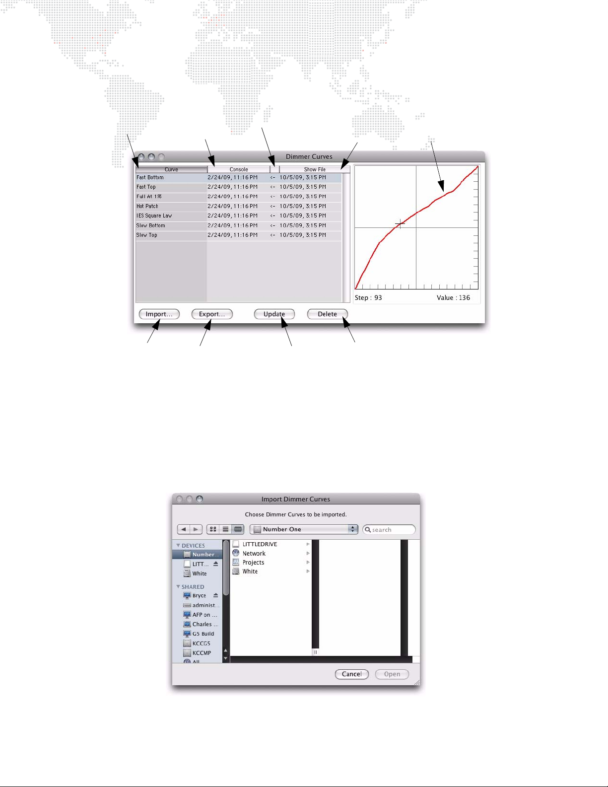
Step 3. To move file in the direction selected, click Update at bottom of window. This will copy the file in the
Deletes Selected
Dimmer Curve
Updates Files
Imports Files
Exports Files
Dimmer Curve Graph
Show File
Date/Time
Copy Direction Column
(Clicking in column toggles to arrows)
Console
Date/Time
Curve Name
direction selected. (This is a permanent change.)
To import dimmer curve files:
New dimmer curve files can be imported into the dimmer curves window. Any comma-delimited file can be used as a
dimmer curve file. A dimmer curve file can be created in any text or spreadsheet program. The file must contain
intensity values for each step (0-255) separated by commas. For example, entries in a dimmer curve file look like:
0,0,1,1,2,3....
Step 1. At Dimmer Curve window, click Import.
Step 2. At Import Dimmer Curves window, select file location (disk or folder). Click on file name. Click Open.
36 VX76 SOFTWARE USER MANUAL
Page 53
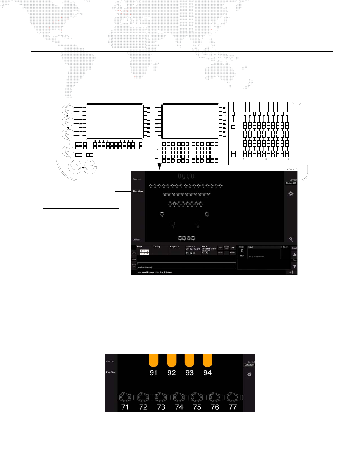
PLAN VIEW
Run
Stop/
Step
Go
BackGoBack
Go
Run
Step
Stop/
RunRun
Stop/
Step
Select
Load
Load
Select
Out
Black
Grand
Master
Select
Load Load
Select Select
Load
Select
Load
Select
Load
Select
Load
Select
Load
Select
Load
8
5
2
Thru
0
Fill
Track/
Undo
Sneak
Update
Copy/
Move
Delete
Shift
Option
Label
Recall
Cmd
Store
Sel
Store
Color
Set
Dynam?Group
Help
Patch
Effect
Present
Step
.
Seq
Beam
1
4
Macro
Chan
Type
Unpark
Park/
Fan
Board
Cue
Cue
Shot
Snap
Dimmer
7
+
Block
Speed
FullClear At
3
6
Delay
Time
Enter
Sub
Trail
Loop
9
-
Wait
Link
Time
Rate
Out
Pan
Flip
High
Light
Intensity
Out
Full
Close
Open
Zero
Mark
Tilt
NextLast
111212 14413315517716618
8
9
19
20
10
Bank
Func
Run
Stop/
Step
Back
Go
Solo
4
Bump
Solo
Bump
Board
Control
Go
Stop/
Back
123
Solo
Bump
Solo
Bump
Run
Stop/
Step
Back
Go
BackGoBack
Go
Run
Stop/
Step
Run
Stop/
Step
Stop/
Step
Back
Solo
Bump
Solo
Bump
567
Solo
Bump
Solo
Bump
8109
Solo
Bump
Solo
Bump
Run
Stop/
Step
Back
Go
BackGoBack
Go
Run
Stop/
Step
Press "Plan View"
Note: The V676 console is
shown in this example,
however, touchscreen
controls apply to both the
V676 and V476 consoles. For
the V276 On Mac console,
access the Plan View in the
software windows.
Touch icon to select
(Touch icon again to deselect)
General Plan View Operation
All patched luminaires are displayed in the Plan View. Operation of the Plan View can be done from the central
touchscreen (available on the front panel - V476/V676 only) or the Plan View window (available from the Setup menu).
The operations are basically identical whether you are using the touchscreen or software window.
Selecting Channels
The touchscreen allows for selecting luminaire icons (channels).
To select/deselect single channels:
+ At Plan View, touch icon(s). Selected icons will be highlighted in orange.
+ Touch again to deselect.
VX76 SOFTWARE USER MANUAL 37
Page 54
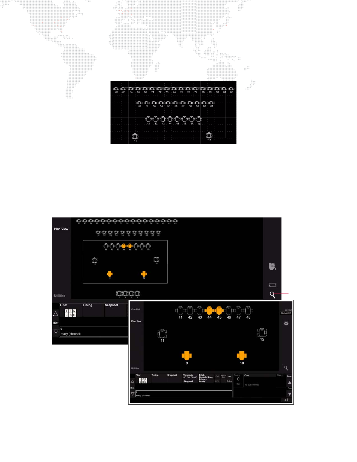
To select/deselect multiple icons at once:
Zoom Box
Zoomed Area
Wide View
Zoomed View
Zoom Icon
Zoom To
Selection
+ Using finger, drag box around icons you wish to select. Selected icons will be highlighted in orange.
+ Double-tap in Plan View to deselect all icons.
+ Press Cmd+A on the Mac keyboard to select all fixtures.
Zoom
Selected areas can be zoomed using the zoom controls.
To zoom into a selected area:
Step 1. At Plan View, touch white Zoom icon. (When Zoom mode is active, luminaire icons will not be selected when
dragging to create a box.)
Step 2. Using finger, drag box around desired zoom area.
Step 3. Touch Zoom icon to toggle back and forth from zoomed area to wide view.
To create a new selection box:
+ While in Zoom mode, a new selection box can be created by dragging finger across a new area.
38 VX76 SOFTWARE USER MANUAL
Page 55
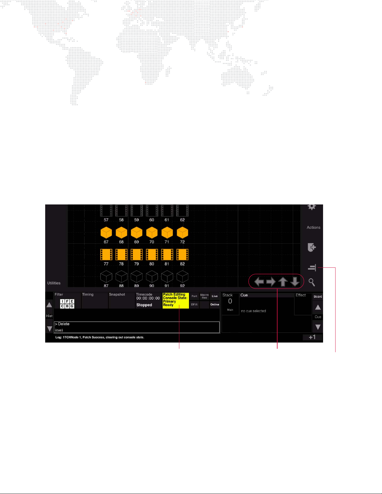
To recenter selection box:
Nudge Controls
Align Icon
Patch Editing Button
+ While in Zoom mode, tap in Plan View to recenter the selection box at any time.
To zoom to selected fixture:
+ While in Zoom mode, select a fixture icon then press the Zoom-To-Selection icon.
Pan
The view can be panned.
To pan the view:
+ Press and hold [Shift] while dragging finger in Plan View. The viewing angle will be panned as you drag.
Nudge and Align
When Patch Edit mode is enabled, several new action icons appear at the right of the Plan View.
To nudge a fixture(s):
Step 1. Enter Patch Edit mode by pressing Patch Editing button.
Step 2. Select fixture icon and use nudge arrows to move fixture. The arrows will be displayed at the bottom of the
layout when fixtures are selected. (Selected fixtures can be repeatedly nudged by holding down the nudge
arrows.)
To align fixtures:
When multiple fixture icons are selected, the Align icon will be displayed at the right of the Plan View.
Step 1. Enter Patch Edit mode by pressing Patch Editing button.
Step 2. Select multiple fixtures.
Step 3. Press Align icon to bring up alignment options.
VX76 SOFTWARE USER MANUAL 39
Page 56
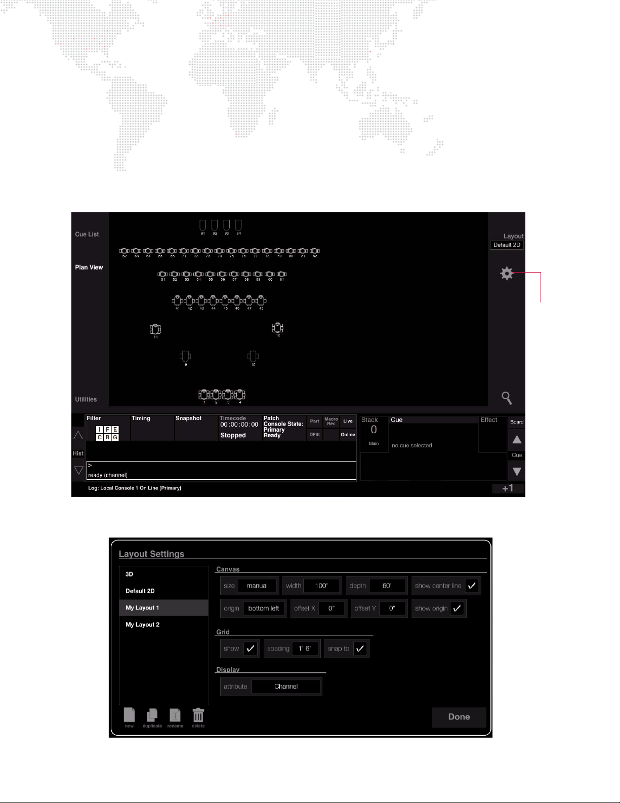
Plan View Settings
Gear
Button
Various Plan View options can be set using the Layout Settings screen.
+ Canvas - sets options for the Plan View size, dimensions, and origin.
+ Grid - sets Plan View grid size, visibility, snap option.
+ Display - sets the attribute which will be displayed under the fixture icon in the Plan View. By default, the channel
numbers are displayed, but this can be changed using the Attribute pop-up menu.
To configure Plan View settings:
Step 1. At Plan View, press the gear button to open Layout Settings screen.
Step 2. At Layout Settings screen, configure settings as required and press
40 VX76 SOFTWARE USER MANUAL
Done.
Page 57
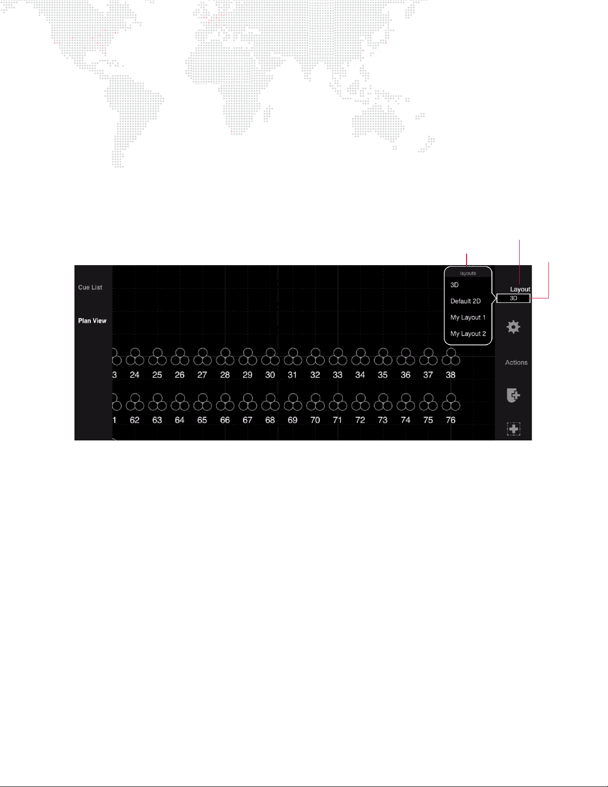
Plan View Layouts
Layout Button
Layout Selection Menu
Current
Layout
The Plan View can be displayed in either a 2D or 3D layout, or custom layouts may be created.
2D/3D Layouts
The Plan View includes two pre-configured layouts which will display the fixtures according to either 2D or 3D data.
(The 2D Layout is the default.)
To change layout:
Step 1. At Plan View, press
Step 2. At layout selection menu, select new layout. (If custom layouts have been created, these will be included in
the list.)
Layout.
Custom Layouts
Custom layouts can be added to the Plan View beyond the included 2D and 3D layouts.
Guidelines:
+ Each custom layout can have its own settings.
+ Fixtures may be hidden from custom layouts as desired.
+ When creating a new layout, the console starts with the current default 2D Layout. This means that if the 2D
Layout has been changed, then it will be reflected at the starting point of the new custom layout.
+ If a new fixture is patched on a custom layout, the fixture will be hidden on any other custom layout that has
hidden fixtures. In other words, it will only be visible on the layout in which it is patched and on any custom
layouts that do not hide any fixtures.
+ Manipulating layouts places the console in Patch Edit mode.
VX76 SOFTWARE USER MANUAL 41
Page 58
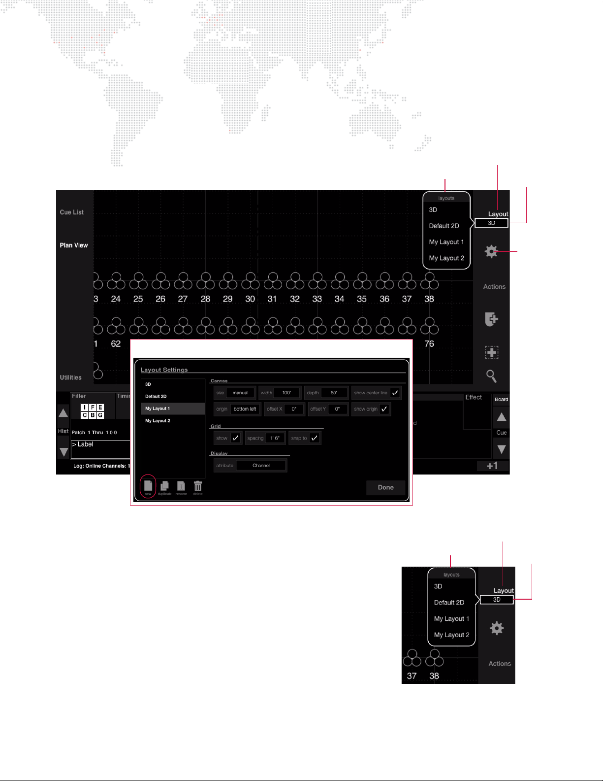
To create a custom layout:
Layout Button
Layout Selection Menu
Current
Layout
Layout Settings Window
Gear
Icon
Layout Button
Layout Selection Menu
Current
Layout
Gear
Icon
Step 1. At console’s central touchscreen, press
Plan View.
Step 2. Press gear icon to open Layout Settings window. At window, press New icon to generate a new layout.
Step 3. Adjust Layout Settings as required.
Step 4. Press
Done to save configuration and close window.
To label a custom layout:
Step 1. Press
Layout to open layout selection menu.
Step 2. Press and hold [Label] while touching a layout name.
Step 3. At keypad, enter alpha/numeric label and press
To delete a custom layout:
Step 1. Press
Step 2. Press and hold [Delete] while touching a layout name.
To edit a layout:
Step 1. Press gear icon to open Layout Settings window.
Layout to open layout selection menu.
Step 2. At left column, select a layout.
Step 3. Adjust settings as required.
Enter.
42 VX76 SOFTWARE USER MANUAL
Page 59
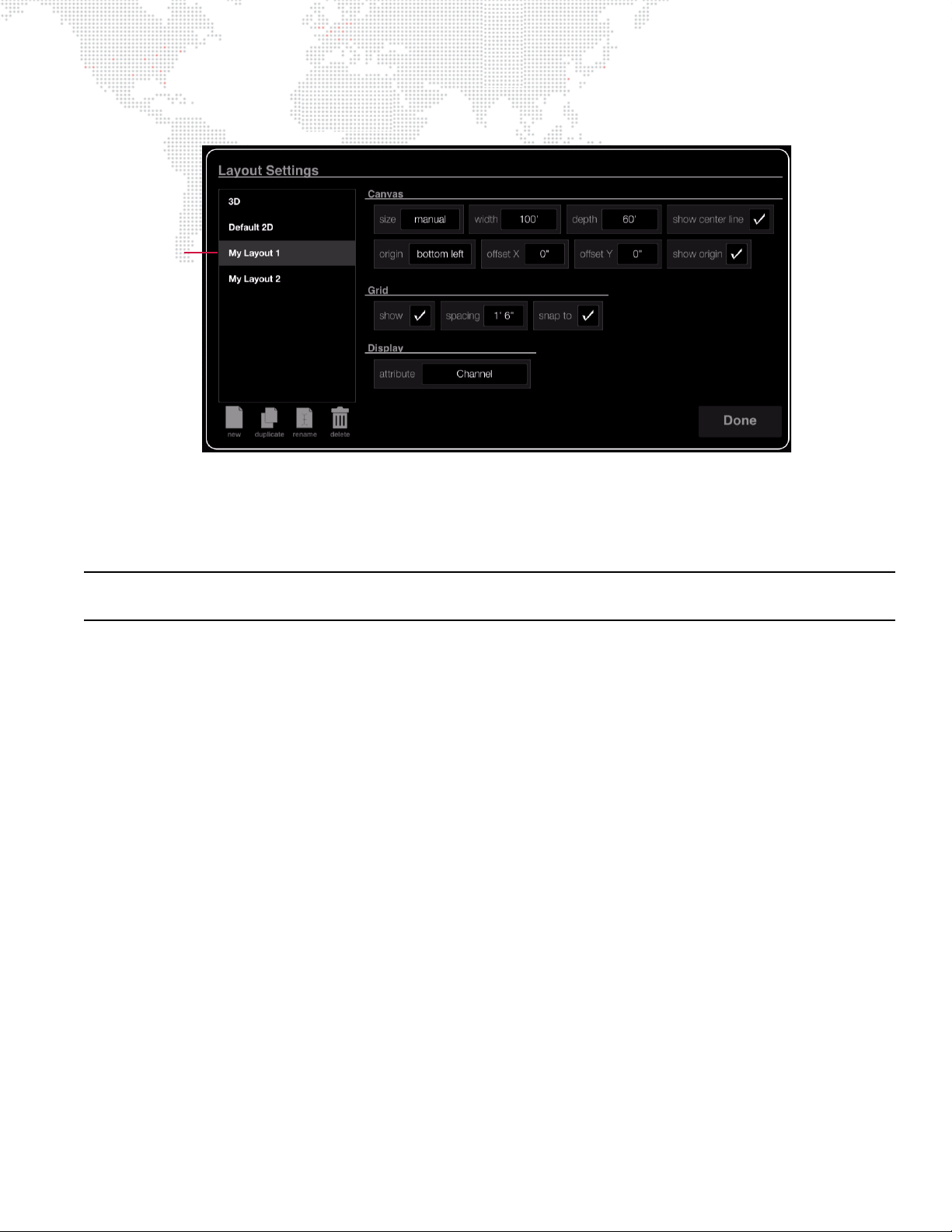
Step 4. Press Done to save configuration and close window.
Selected
Layout
To switch between layouts:
Step 1. Press
Layout to open layout selection menu.
Step 2. At menu, select a new layout. Layout will load into Plan View window.
Caution: If another layout is opened without first saving the patch edit, any changes to the previous layout will be
lost. (Save patch edits by disabling the patch and following the save dialog.)
VX76 SOFTWARE USER MANUAL 43
Page 60
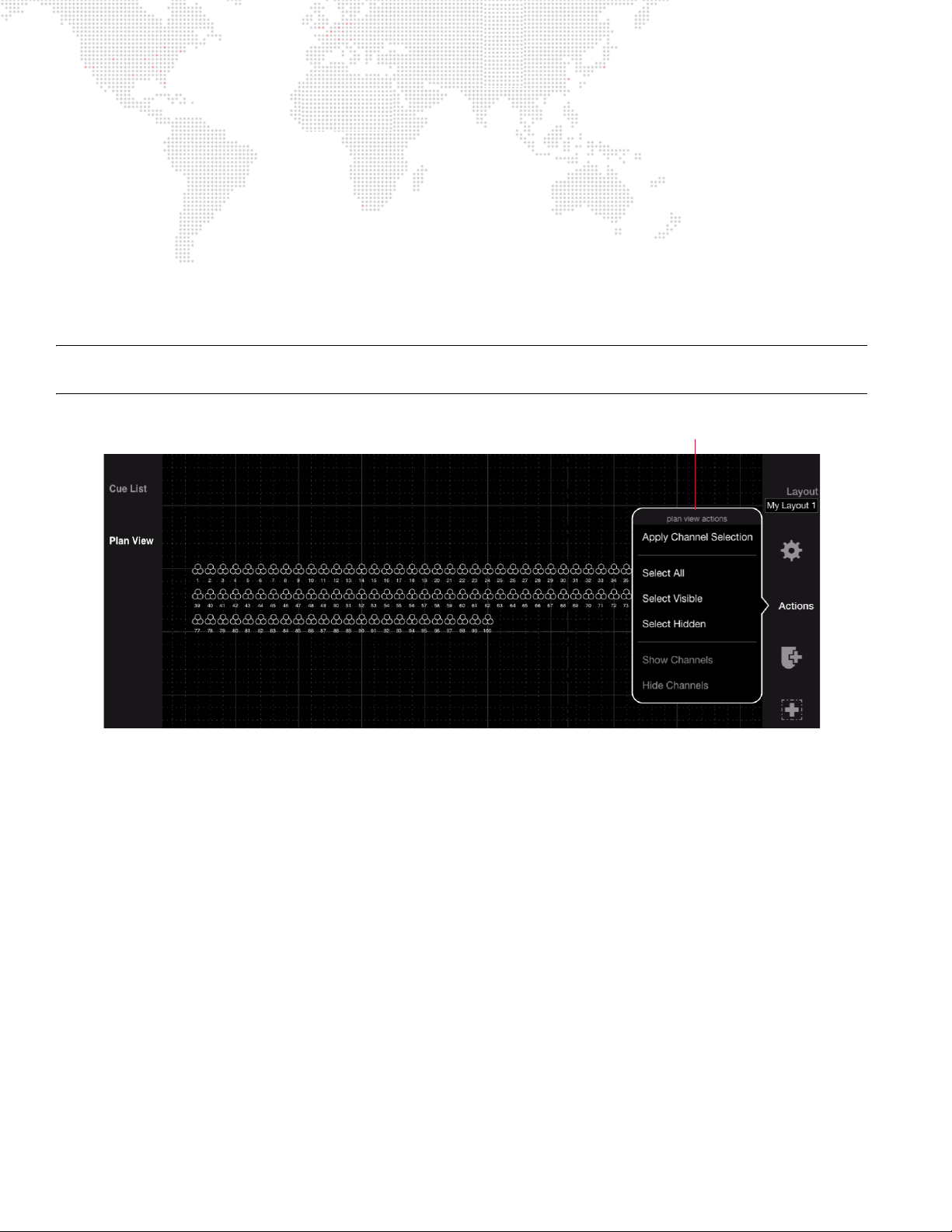
Plan View Actions (Show/Hide)
Actions Menu
Various Plan View options are available from the Actions menu. These options can be used to apply channel selection
and show/hide fixtures in layouts.
+ Apply Channel Selection - takes current channel selection and makes it the patch selection. This only works
when the Plan View is in Patch Edit mode.
+ Select All/Visible/Hidden - these options select either all, the visible, or the hidden channels in the current layout.
+ Hide Channels - hides the currently selected channels in the layout. This action only works with custom layouts
and will be grayed out when the standard 2D or 3D layouts are active.
+ Show Channels - shows (unhides) the currently selected channels in the layout. This action only works with
custom layouts and will be grayed out when the standard 2D or 3D layouts are active.
Note: Hidden fixtures only show up in Patch Edit mode. They are displayed in a lighter outline to indicate that they are
currently in the hidden state.
To apply channel selection:
Step 1. Select one or more channels on the console.
Step 2. Press
To select channels in Plan View:
Step 1. Press
Step 2. Choose "Select All," "Select Visible," or "Select Hidden" as required. The corresponding channels will be
To hide channels:
Step 1. Press
Step 2. Select one or more channels in the layout to hide.
Step 3. Press
To show (unhide) channels:
Step 1. Press
Step 2. Select one or more hidden channels in the layout.
Step 3. Press
44 VX76 SOFTWARE USER MANUAL
Actions and choose "Apply Channel Selection."
Actions
selected in the Plan View.
Layout and choose a custom layout.
Actions and choose "Hide Channels."
Layout and choose a custom layout.
Actions and choose "Show Channels."
Page 61
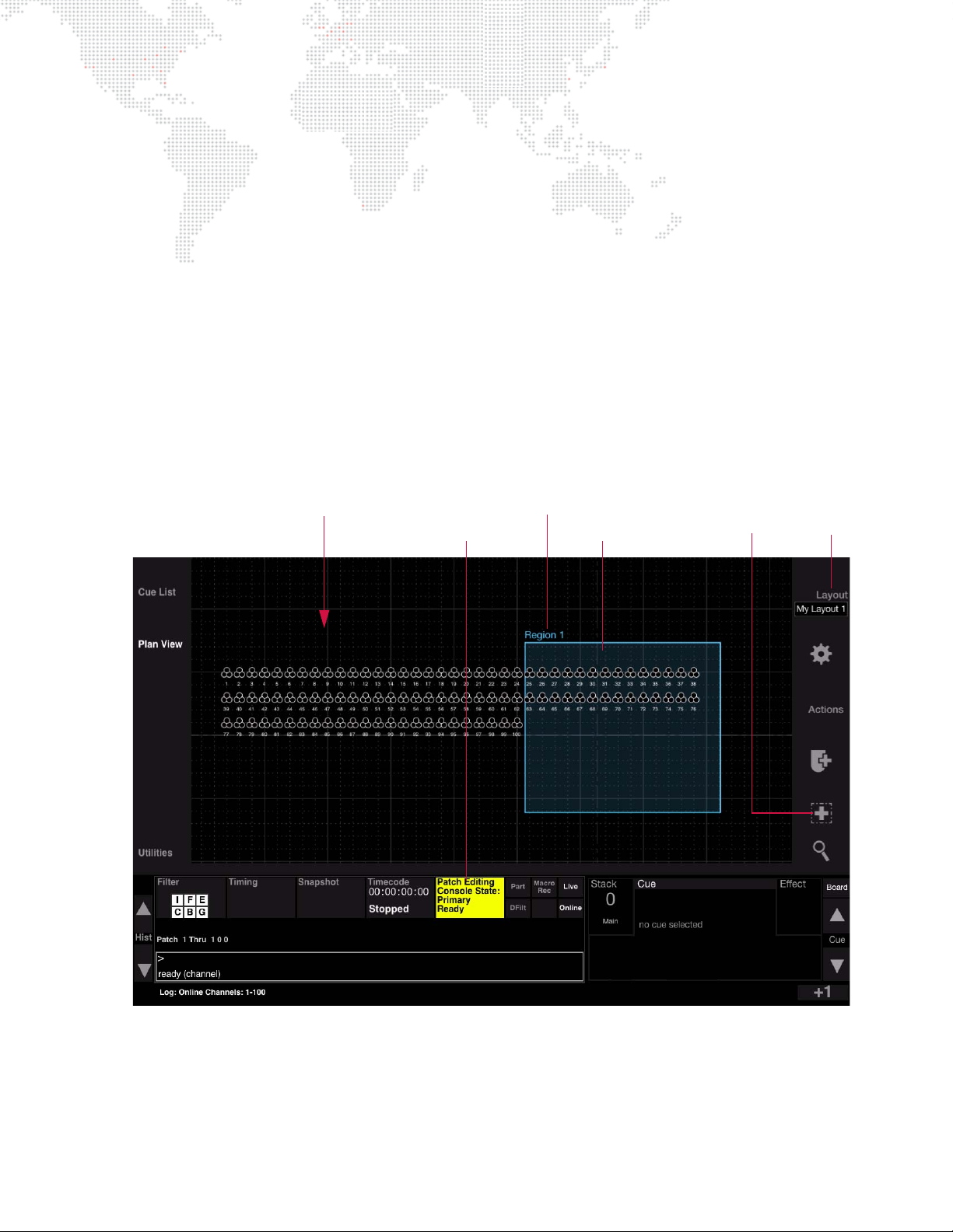
Plan View Regions
Region Box
Layout
Plan View Layout
Region
Patch Editing Button
Button
Region Name
Tool Icon
The Regions feature allows rectangular areas to be drawn on the Plan View for use as organizational tools. The region
contains meta data for the included fixtures so that they can easily be added to groups, presets, cues, etc. based on
their location. It also provides an easy method for selecting fixtures within a region.
Guidelines:
+ Multiple regions may be created.
+ Regions can overlap.
+ Regions can be labeled and deleted as desired.
+ Regions are exclusive to the layout on which they are drawn.
To create a region:
Step 1. At console’s central touchscreen, press
Step 2. Press
Layout and choose a target layout for the region using selection menu.
Step 3. Enter Patch Edit mode by pressing Patch Editing button.
Step 4. Press region tool icon. (It will highlight.)
Step 5. At Plan View, draw a region by dragging finger until the desired size box is created.
Plan View.
To label a region:
Step 1. Press and hold [Label] while touching the region’s name on the Plan View.
Step 2. At keypad, enter alpha/numeric label and press
Enter.
VX76 SOFTWARE USER MANUAL 45
Page 62
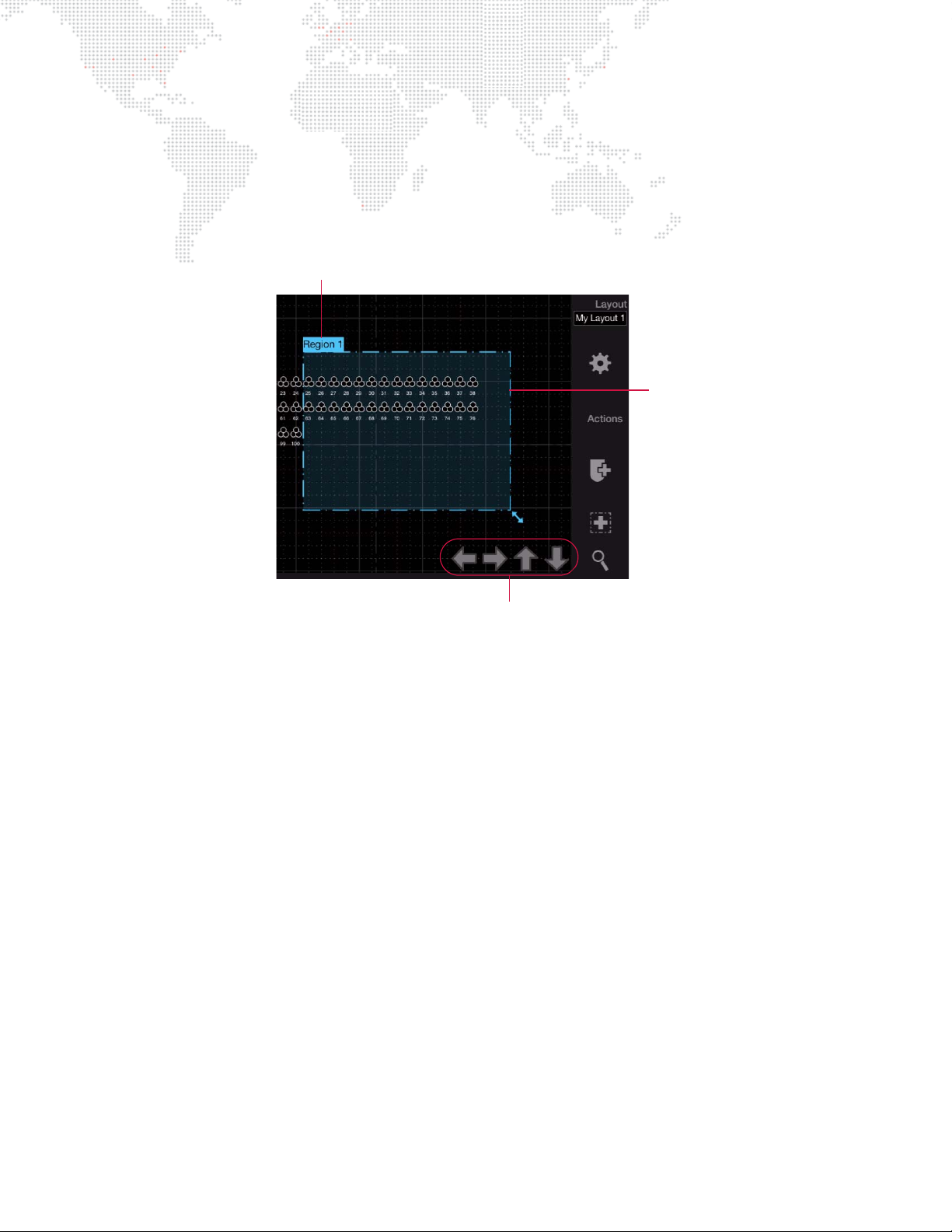
To edit a region:
Nudge Controls
Region Name
Edit Mode
(dashed line)
Step 1. Touch region name. (Name will be highlighted in a box and the region outline will change to a dashed line.)
Step 2. To move, drag box’s label to a new location. Or, use the four arrows at the bottom of the Plan View to nudge
the box right, left, up, or down.
Step 3. To resize, drag bottom-right corner (enlarge or reduce).
Step 4. Double-tap outside of box to turn off editing mode.
To delete a region:
+ Press and hold [Delete] while touching the region’s name on the Plan View.
To select/deselect fixtures in a region:
Step 1. Be sure console is not in Patch Edit mode.
Step 2. Open layout which contains the region. (2D, 3D, custom layout, etc.)
Step 3. Touch region inside box. All fixtures in that region will be selected.
Step 4. Touch again to deselect.
46 VX76 SOFTWARE USER MANUAL
Page 63
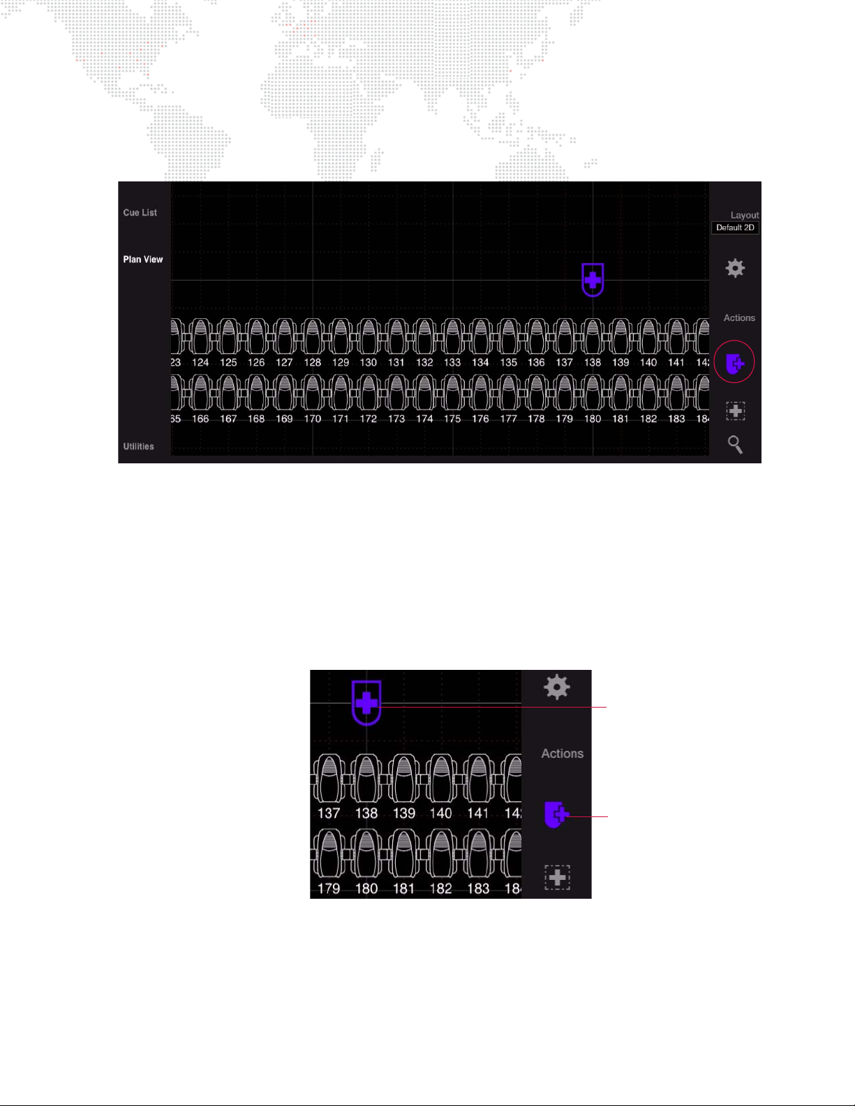
Patch Fixtures in Plan View
"Add Fixture" Icon
Placement Icon
An Add Fixture icon is available in the Plan View while patch is enabled. This feature provides an alternate method for
patching fixtures that sets the 2D and/or 3D location when the fixture is placed.
To patch a fixture using the Add Fixture icon:
Step 1. Make sure patch is enabled. (Refer to "Enabling/Disabling Patch Editing" on page 28.)
Step 2. Press Add Fixture icon. (It will highlight.)
Step 3. Touch within the Plan View area to place fixture (at the touched location). The placement icon will remain to
show the position of the next fixture patched from the command line.
Shortcut:
Pressing and holding [Option] while placing the fixture will patch another fixture of the same type with the next
channel number and DMX address.
Edit Fixture From Plan View
With Patch enabled, double-click a fixture to bring up the edit dialog.
VX76 SOFTWARE USER MANUAL 47
Page 64

Notes
48 VX76 SOFTWARE USER MANUAL
Page 65

3.
MANUAL CONTROL
This chapter provides instructions for controlling luminaires in order to build cues.
+
CHANNEL SELECT
+ LAMP CONTROL
+ ENCODER CONTROL
+ KEYPAD CONTROL
+ LUMINAIRE STATUS
Page 66
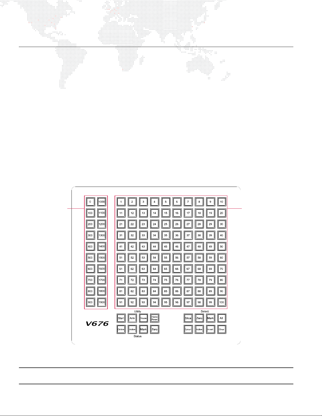
CHANNEL SELECT
Century Buttons Routes the 100button Array to
one of 19 pages.
100-Button Array Represents a group
of 100 channels as
determined by the
Century Button
selection.
Overview
When the patch was defined in the previous chapter, each luminaire was assigned to a control channel (refer to "Patch
Overview" on page 26). Selecting the channel will give you control of the luminaire’s parameters in order to build cues
or to store as groups of channels, presets, palettes, etc.
In addition to the methods of channel selection covered in this section, channels can also be selected in the Plan View
and 3D Graphic windows. However, these methods are covered along with the respective topics elsewhere in this
manual:
+ For selecting channels via the Plan View, refer to "Plan View" on page 37.
+ For selecting channels via the 3D Graphic software window, refer to "Using 3D Graphic Window" on page 325.
Selecting Channels
Channel numbers can be selected or deselected from the Channel Select panel, Channel Select window, or
command-line keypad. When selecting channels, the channels will highlight in the window, on the Channel Select
panel and their respective icons will be highlighted in the Plan View.
From Channel Select Panel (V476/V676 Only)
Figure 3-1: External Channel Select Panel
Note: When selecting channel numbers greater than 2000, this can only be done via command-line keypad and
groups, since the Channel Select panel only accommodates 2000 channels in its hard buttons.
50 VX76 SOFTWARE USER MANUAL
Page 67

Eight select buttons are available for simplifying channel selection:
Invert
MarkSlice Zero
Cl ear
All
Online Active
Mark Zero
Start Arm
Douse
Home
Reset
+ [Slice] -
+ [Zero] - selects all channels in a
+ [Mark] - selects all
for future use.
marked
zero
* channels.
* state.
+ [All] - selects all patched channels.
+ [Dynam] -
+ [Active] - selects all channels with
for future use.
active
* luminaires.
+ [Invert] - deselects currently selected channels and selects all other patched channels.
+ [Clear] - clears all channel selections.
Four status mimic buttons are available. These buttons highlight as indicators rather than as a selection tool:
+ [Online] - indicates all online luminaires.
+ [Active] - indicates all luminaires that are
+ [Mark] - indicates all luminaires that are
+ [Zero] - indicates all luminaires that are in a
active
marked
zero
*.
*.
* state.
Four luminaire utility buttons are also available. These apply only to selected luminaires:
+ [Start] - starts lamp for all selected arc luminaires with remote start capability.
+ [Douse] - douses lamp for all selected arc luminaires with remote start capability. Press and hold [Arm] while
pressing [Douse] to send the douse command.
+ [Arm] - must be held along with [Douse] or [Home/Reset] to complete the command.
+ [Home/Reset] - dual action button.
[Home] sets all parameter timing to zero and clears any intensity Mark or Zero states. Press and hold [Arm] while
pressing [Home/Reset] once.
[Reset] recalibrates luminaires. Press and hold [Arm] while pressing [Home/Reset] twice.
Also refer to "Home / Reset (Recalibration)" on page 59.
* Active - luminaires with intensity greater than zero (1-100%).
Marked - luminaires with an intensity state of "marked."
Zero - luminaires with an intensity state of zero ("hard zero", 0% level).
(For a more in-depth explanation, refer to "Intensity States" on page 140).
VX76 SOFTWARE USER MANUAL 51
Page 68

Select a single channel (or multiple single channels):
Tip
Step 1. At Century Buttons, press [0] through [1900] as required. Button will light.
Step 2. At 100-Button Array, press button of channel number to be selected, [1] through [100]. Button will light.
Step 3. To select multiple single channels, continue selecting channels (channel selections "pile on").
Example
:
To select channel 521, press the page [500] button and then press [21] on the 100-button array.
Select a range of channels:
Step 1. At Century Buttons, press [0] through [1900] as required. Button will light.
Step 2. At 100-Button Array, press button of first channel number to be selected. Then, while holding down first
button, press button of last number in range. First and last buttons will light, as will all those in-between.
Select channels on multiple pages:
Step 1. At Century Buttons, press [0] through [1900] as required. Button will light.
Step 2. At 100-Button Array, press button of first channel number to be selected. Then, while holding down first
button, press button of last number in range. First and last buttons will light, as will all those in-between.
Step 3. Press next required page ([0] through [1900]). First page number button will flash to show that channels are
selected on that page.
Step 4. Press buttons for channels to be selected.
Step 5. Repeat Steps 3 through 5 as required.
Deselect a single channel (or multiple single channels):
+ Press any selected channel button(s) to deselect.
Deselect a range of channels:
+ Press button of first selected channel button to be deselected. Then, while holding down first button, press button
of last number in range. The range will be deselected.
To select a single channel and deselect all others, double-click on any channel button.
Note: The
order
of channel selection is retained when storing a Group. Refer to "Ordered Groups" on page 131.
52 VX76 SOFTWARE USER MANUAL
Page 69
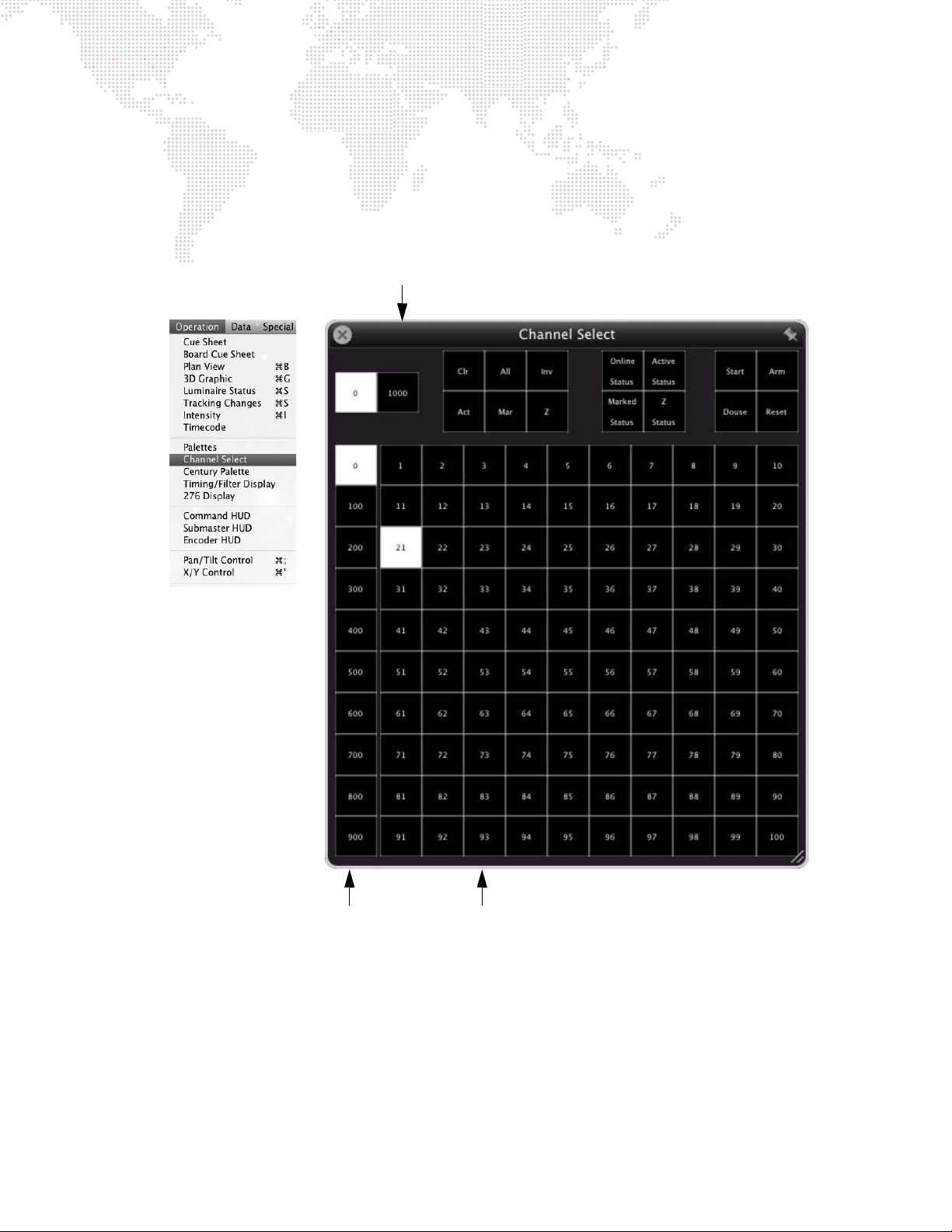
From Channel Select Window
Century Buttons (0-900) Routes the 100-button array
to one of ten pages
100-Button Array Represents a group of 100 channels as determined
by the millennium and century buttons
[1000] Millennium Button - Routes control to first 1000 channels when not
selected / routes control to second 1000 when selected.
Selecting channels from the Channel Select window is similar to selecting channels in the Channel Select panel.
+ Open the window by selecting Channel Select at the Operation menu.
+ Click the pin icon at the top-right corner to keep the Channel Select on top of other windows. (When pinning is
active, the pin icon will turn from gray to white.)
VX76 SOFTWARE USER MANUAL 53
Page 70

Six buttons are available for simplifying channel selection:
+ [Clr] - clears all channel selections.
+ [All] - selects all patched channels.
+ [Inv] - (Invert) deselects currently selected channels and selects all other patched channels.
+ [Act] - selects all channels with
+ [Mar] - selects all
marked
+ [Z] - selects all channels in a
active
* channels.
zero
* state.
* luminaires.
Four status mimic buttons are available. These buttons highlight in purple as an indicator rather than as a selection
tool:
+ [Online Status] - indicates all online luminaires.
+ [Active Status] - indicates all luminaires that are
+ [Marked Status] - indicates all luminaires that are
+ [Z Status] - indicates all luminaires that are in a
active
marked
zero
*.
*.
* state.
Four luminaire utility buttons are also available:
+ [Arm] - must pressed first (it will latch on) before pressing [Douse] or [Home/Reset] to complete those commands.
(This prevents accidental dousing or reset actions.)
+ [Start] - starts lamp for all selected arc luminaires with remote start capability.
+ [Douse] - douses lamp for all selected arc luminaires with remote start capability. Press [Arm] then press [Douse]
to send the douse command.
+ [Home/Reset] - dual action button.
[Home] sets parameters to defaults. Press [Arm] then press [Home/Reset] once to send the home command.
[Reset] recalibrates luminaires. Press a [Arm] then press [Home/Reset] twice to send the reset command.
Also refer to "Home / Reset (Recalibration)" on page 59.
* Active - luminaires with intensity greater than zero (1-100%).
Marked - luminaires with an intensity state of "marked."
Zero - luminaires with an intensity state of zero ("hard zero", 0% level).
(For a more in-depth explanation, refer to "Intensity States" on page 140).
54 VX76 SOFTWARE USER MANUAL
Page 71

Select a single channel (or multiple single channels):
Step 1. Select [1000] as required.
Step 2. Select [0] through [900] as required. Button will light.
Step 3. Select button of desired channel. Button will light.
Step 4. To select multiple single channels, continue selecting buttons of channels to add (selections "pile on").
Example
: To select channel 521, ensure that [1000] button is not active, select the page [500] button and
then select [21] on the 100-button array.
Select a range of channels:
Step 1. Select [1000] as required.
Step 2. Select [0] through [900] as required. Button will light.
Step 3. Select button of first channel. Then, while holding mouse button down, drag across range of channels
(mouse)
or
drag finger across range of channels (touchscreen).
Select channels on multiple pages:
Step 1. Select [1000] as required.
Step 2. Select [0] through [900] as required. Button will light.
Step 3. Select required channels.
Step 4. Select next required page ([0] through [900]). First page button will be dimly highlighted to show that
channels are selected on that page.
Step 5. Select required channels on new page.
Step 6. Repeat Steps 4 and 5 as required.
Deselect channels:
+ Press any selected channel button(s) to deselect.
Note: The
order
of channel selection is retained when storing a Group. Refer to "Ordered Groups" on page 131.
VX76 SOFTWARE USER MANUAL 55
Page 72
From Keypad
Shift
Option
Cmd
123
.0
Clear
At EnterFull
789
Time
456
Sub
Rate
Link
+
Thru
-
Loop
Force
Mark
Cue/
Delay/
Speed
Track
Back
Track/
Wait/
Trail
SneakLabel
Move
Delete
Copy/
Sel
Park/
PatchUndoRecall
Store
Unpark
Update
Grab
Help
Query/
Store
Block/
UnBlk
Revert
Manual/
Effect Set Seq
DynamGroup Step
Snap
BeamColorPreset
Macro
Shot
Chan
Cue/
Stack
Board
Cue
ready (channel)
Tip
Channels may also be selected using the command-line keypad, available on the front panel.
Guidelines:
+ Any combinations of [ + ], [ - ], and [Thru] are
allowed.
+ Pressing [Enter] completes the channel selection.
+ Because the keypad always defaults to channel
entry mode, use of the [Chan] (channel) button is
optional.
Select a single channel:
+ <Chan> [n] [Enter].
Select multiple channels:
+ <Chan> [m] [+] [n] [Enter].
Select a range of channels:
+ <Chan> [m] [Thru] [q] [Enter].
Select multiple channels including a group:
+ <Chan> [m] [+] [Group] [n] [Enter].
Select all active channels:
+ [Chan] [Enter].
Other examples:
+ <Chan> [m] [+] [s] [Thru] [w] [Enter].
+ <Chan> m] [+ ] [s] [Thru] [w] [-] [t] [Enter].
[Clear]
[Clear] functions as a backspace key when used during command-line construction. For example, <Chan> [n] [Thru]
[t] [Clear] [s] [Enter] results in the selection of channels n thru s. When [Clear] is used after an [Enter] (fully terminated
command line), the command line is cleared.
The only thing that clears a syntax error on the command line is [Clear]. Any other keypad entry is ignored until the
error condition is cleared.
Holding down [Clear] will clear an entire unterminated command line.
Note: The
56 VX76 SOFTWARE USER MANUAL
order
of channel selection is retained when storing a Group. Refer to "Ordered Groups" on page 131.
Page 73
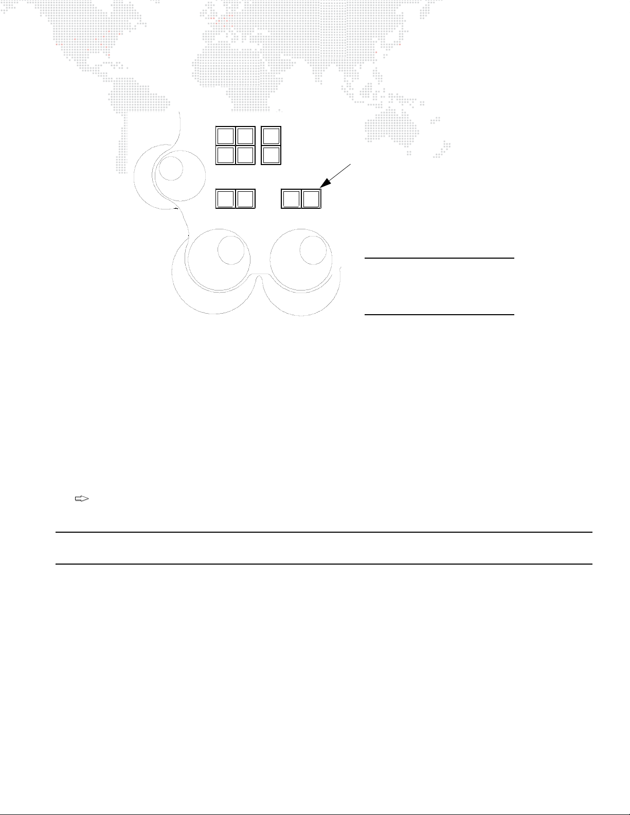
[Next] and [Last]
TiltPan
Intensity
Full Mark
Out Zero
Last Next
High
Light
Flip
Open
Close
[Next] and [Last] Buttons
Note: The V676 console is
shown in this example, however,
these buttons are found on all
Vx76 console front panels.
Tip
The [Next] and [Last] buttons will step through all channels.
Figure 3-2: Next and Last Buttons
+ [Next] - increments the channel selection by one.
+ If a single channel were selected (either with the keypad or the 100 button array), pressing [Next] will increment
the channel selection by one. If a range of channels is selected, the first press of [Next] will select the first channel
in that range. Subsequent presses will increment the channel selection by one, but will not select a channel
outside the range.
+ [Last] - decrements channel selection by one.
+ If a single channel were selected (either with the keypad or the 100 button array), pressing [Last] will decrement
the channel selection by one. If a range of channels is selected, the first press of [Last] will select the last channel
in that range. Subsequent presses will decrement the channel selection by one, but will not select a channel
outside the range.
Press and hold [Next] while pressing [Last] to reselect the original channel range.
Note: When working with Ordered Groups, Next/Last will follow original selection order. Refer to "Ordered Groups"
on page 131.
VX76 SOFTWARE USER MANUAL 57
Page 74
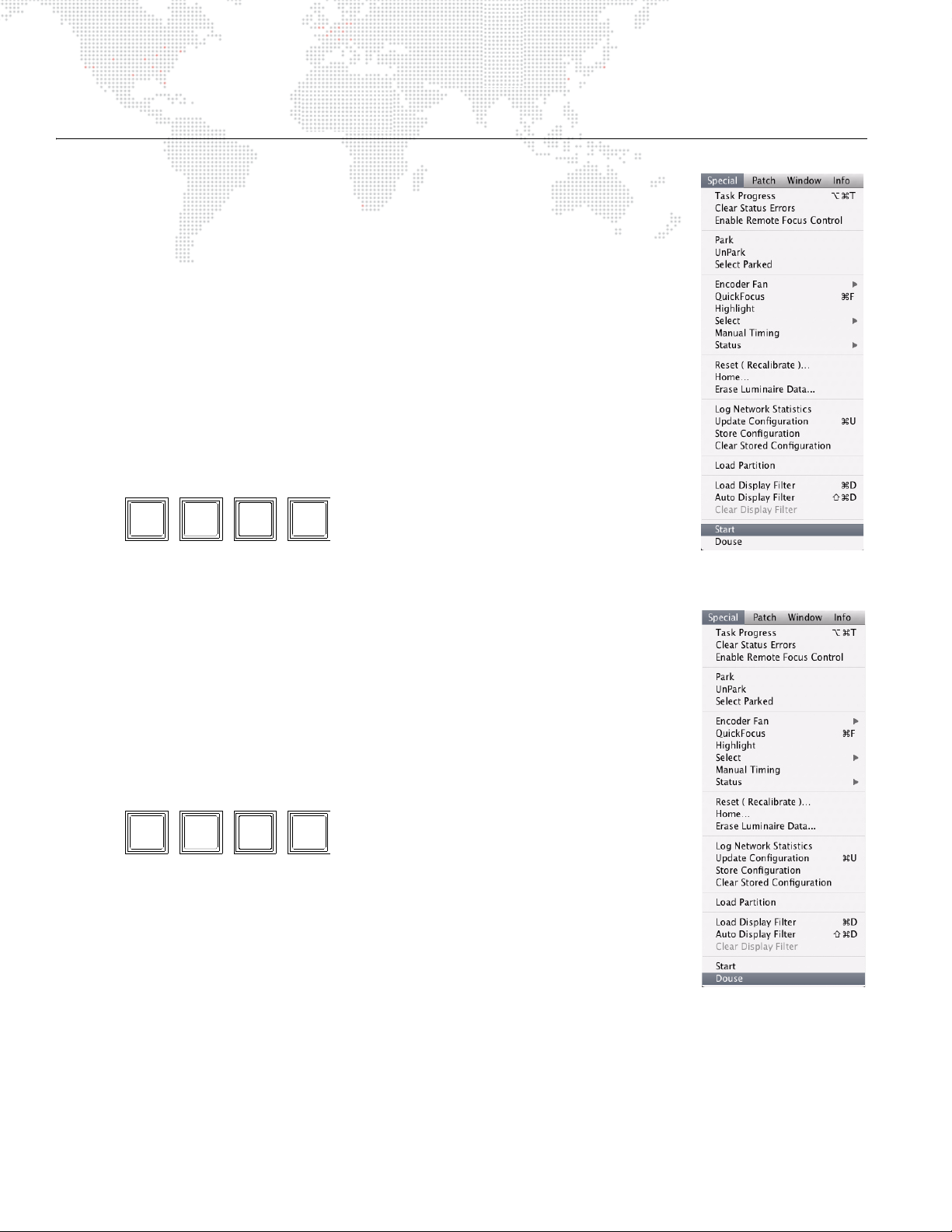
LAMP CONTROL
Utility
Start Arm
Douse
Home
Reset
Utility
Start Arm
Douse
Home
Reset
Start
Start will function for all arc luminaires with remote start capability.
Start lamps using menu bar:
Step 1. Select required channels.
Step 2. Set luminaire(s) in recommended starting position according to manufacturer’s
specifications.
Step 3. At Special menu, select Start.
Start lamps using [Start] button:
Step 1. Select required channels.
Step 2. Set luminaire(s) in recommended starting position according to manufacturer’s
specifications.
Step 3. At Channel Select panel, press [Start].
Douse
Douse will function for all arc luminaires with remote douse capability.
Douse lamps using menu bar:
Step 1. Select required channels.
Step 2. At Special menu, select Douse.
Douse lamps using [Douse] button:.
Step 1. Select required channels.
Step 2. At Channel Select panel, press and hold [Arm] while pressing [Douse].
58 VX76 SOFTWARE USER MANUAL
Page 75
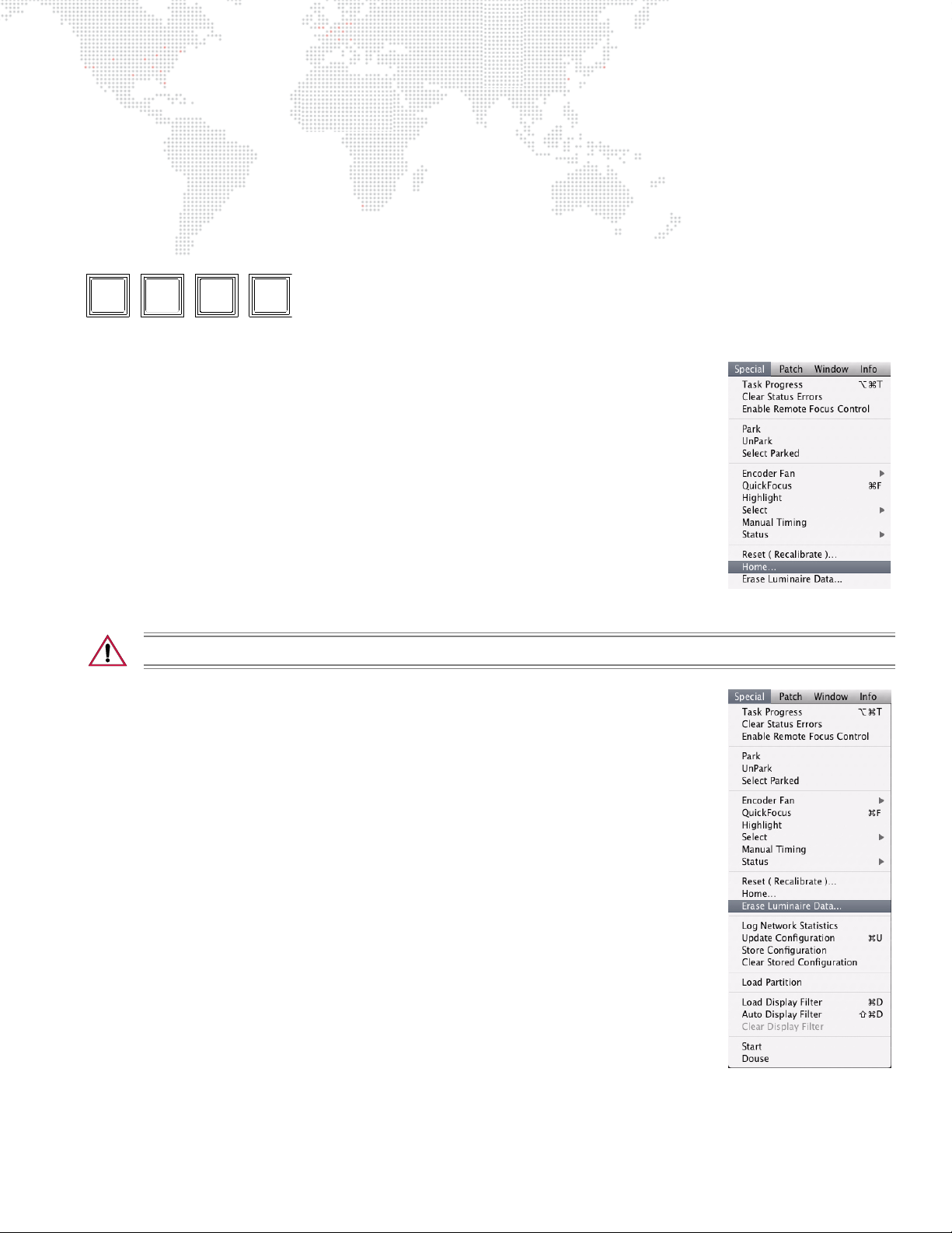
Home / Reset (Recalibration)
Utility
Start Arm
Douse
Home
Reset
The [Home/Reset] button and corresponding menu items provide the following options:
+ Home - sets all parameter timing to zero and clears any intensity Mark or Zero states.
+ Reset - recalibrates luminaire.
[Home/Reset] is dual action button.
Return parameters to defaults (home):
Step 1. Select required channels.
or
Step 2. Press and hold [Arm] while pressing [Home/Reset] once,
Special menu.
Reset (recalibrate) luminaires:
Step 1. Select required channels.
Step 2. Press and hold [Arm] while pressing [Home/Reset] twice,
Special menu.
select Home from
or
select Reset from
Erase Luminaire Data
The Erase Luminaire Data option will erase the luminaire’s data from the show file.
CAUTION: There is NO undo for this action.
Erase luminaire data from show file:
Step 1. Select required channels.
Step 2. At Special menu, select Erase Luminaire Data.
VX76 SOFTWARE USER MANUAL 59
Page 76

ENCODER CONTROL
Overview
The manual control encoders provide control of luminaire parameters. The encoders may be controlled using either
the encoder knobs on the front panel or using the Encoders software window.
Front Panel Encoders
The front panel provides a mix of "hard" and "soft" encoders. Pan, tilt, and intensity parameters are mapped to
permanently assigned "hard encoders," while the remaining parameters are mapped to "soft encoders." The soft
encoders control a variety of parameters depending on which function is currently selected and what type of
luminaires are selected (mapping is based on luminaire capabilities, and therefore, will vary). Soft encoder control
includes the following options:
+ Color - controls color functions such as CMY, RGBAW, wheels, flags, or color plates, plus some additional focus
attributes.
+ Beam - controls edge, beam, zoom, frost, strobe, and prism.
+ Image - controls static gobo, rotating gobo, spin, and effects.
+ 3D - allows scaled adjustments to time and delay (works with Timing Filter) and controls X, Y and Z coordinates
for pan and tilt.
+ Dynamics - modifies rate, size, and offset for dynamics.
+ Frame - controls framing shutters.
By selecting a function, the soft encoders change to control the parameters of that function. These functions are
luminaire specific when selecting single luminaire types. In addition to the encoder, minimum and maximum control
buttons are provided to apply a default setting to selected luminaires. Like the soft encoders, the functionality of these
buttons depends on the currently selected function. The min/max buttons are initially programmed with a default
console setting, but can be reprogrammed with your own settings as required.
For complete instructions on using the front panel encoders, refer to "Front Panel Encoders" on page 61.
Encoders Window
The Encoders window functions just as the front panel encoders, but also provides data for the currently selected cue
or effect, and allows specification of a submaster for cue tracking.
For complete instructions on using the Encoders Window, refer to "Encoders HUD Window" on page 70.
Fan Function
A special fan function is also available to provide five different types of encoder fanning styles.
For complete instructions on using the Fan Function refer to "Fan" on page 71.
60 VX76 SOFTWARE USER MANUAL
Page 77
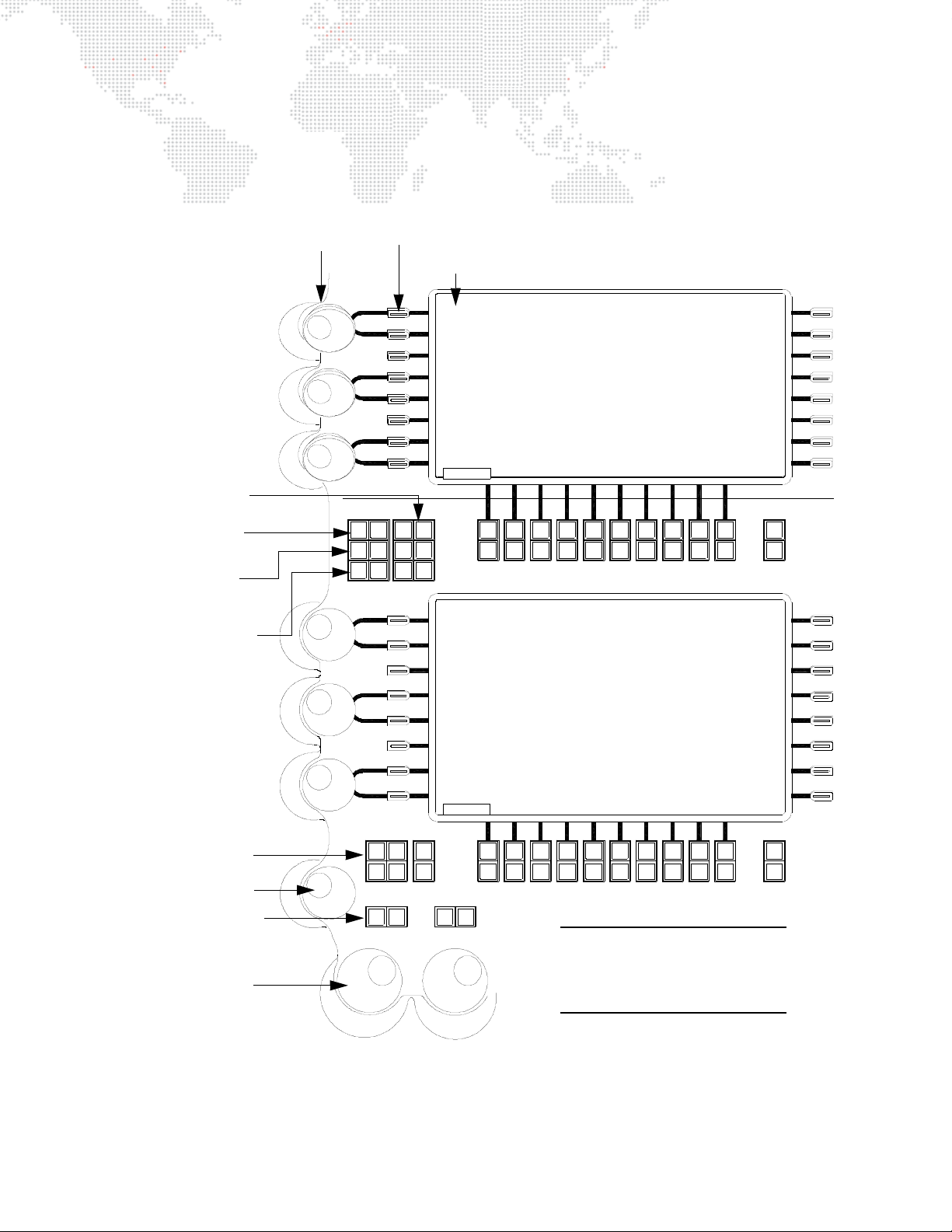
Front Panel Encoders
Bank
Func
12 435 867 910
11 12 1413 15 1816 17 19 20
12 435 867 910
11 12 1413 15 1816 17 19 20
TiltPan
Intensity
Full Mark
Out Zero
Last Next
High
Light
Flip
Fan Effect Frame Image
Slow 3D Beam
Shift Grid Dynam Color
Bank
Func
Open
Close
open
Z Pos
other
open
Wheel2
close
open
Wheel
close
open
Magenta
close
open
Amber
close
open
Blue
close
Function Buttons Press to map a
function to the soft
encoders. Press
once to view first
page, press again
to view second
page (button
toggles between
pages).
Min/Max Buttons - Programmable buttons for quickly accessing minimum or
maximum settings. (Default is set to actual luminaire min and max settings.)
Encoders
Mapped Control Parameters
Color 1
Color 1
Shift - Press and
hold while selecting
a soft encoder
function. This will
access additional
parameters.
Intensity Encoder
Pan and Tilt
Encoders
Intensity States
Fan - provides
encoder fan control.
Slow - Activates
encoder high
resolution mode.
Pan/Tilt Flip Button
Note: The V676 console is
shown in this example, however,
these buttons are also found on
the V476 console front panels.
When a luminaire is selected for manual control, the encoders and buttons available on the front panel can be used to
change its parameters.
Figure 3-3: V676 and V476 Encoder Controls
VX76 SOFTWARE USER MANUAL 61
Page 78
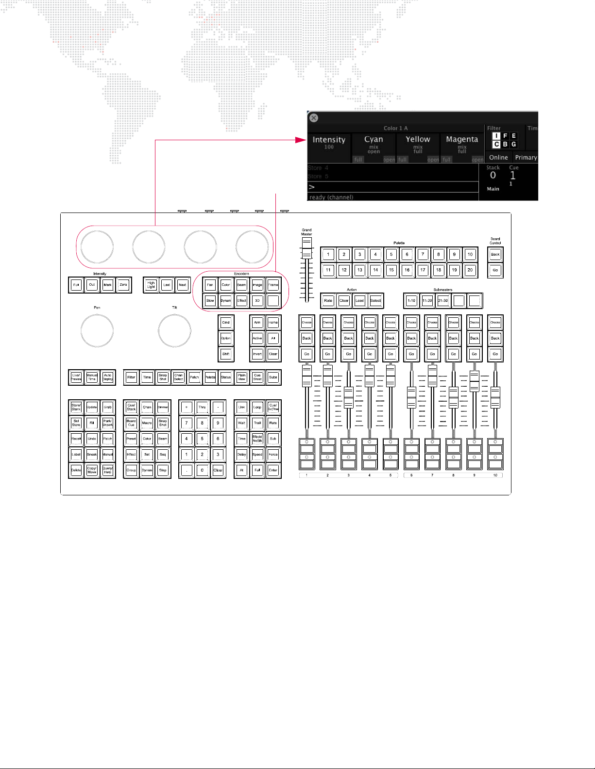
When turning the encoder knobs on the V276 console front panel, the adjusted values will be displayed in the V276
Function Encoders (4) Four knobs which control luminaire parameters
as selected by the Encoder Buttons.
Encoders Buttons Selects a parameter type for
control by Encoder Knobs.
HUD. (For more information about this window, refer to "V276 Display" on page 369.)
Figure 3-4: V276 Encoder Controls
62 VX76 SOFTWARE USER MANUAL
Page 79
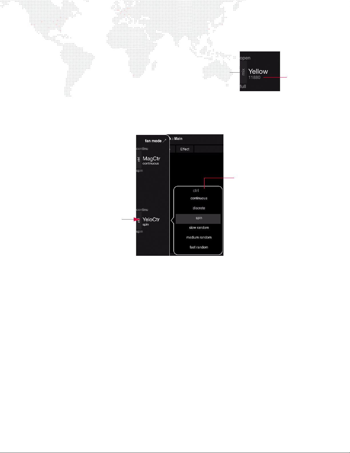
Value/Range Display
Value
Range
Direct Range Options
Touch Parameter
When an encoder function is selected (i.e., Color, Beam, Image,
3D, Dynamics, or Frame), the current value will be displayed in
the touchscreen area and/or V276 HUD.
The value to the left of the encoder label shows the title of the
range, while the value below the encoder label shows the
parameter value or label (such as 'open' or 'full'). The range
labels and defined values are set in the fixture profile.
The displayed value will come from the lowest selected channel.
The direct range and value selection can be changed by touching a parameter in the Encoder Sidebar. When touched,
a list of options will pop-up in the display.
VX76 SOFTWARE USER MANUAL 63
Page 80
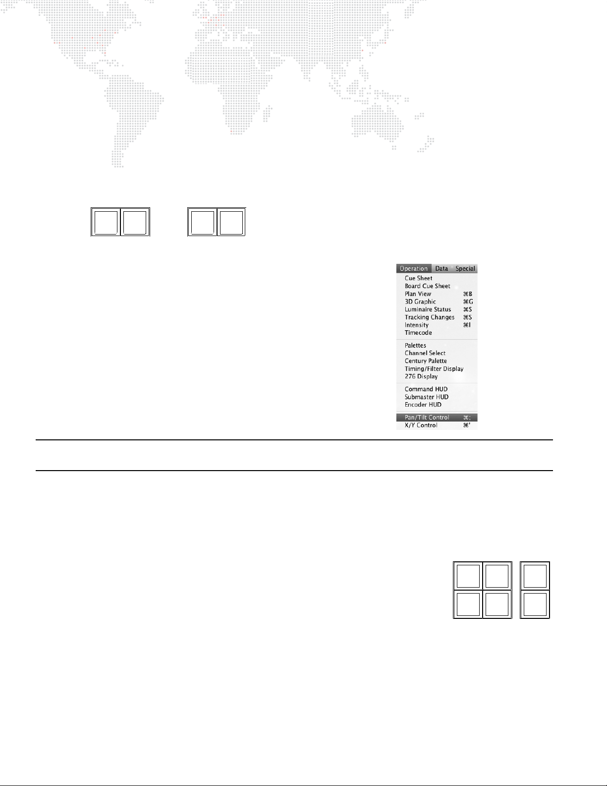
Pan and Tilt
Last Next
High
Light
Flip
Full Mark
Out Zero
Open
Close
Pan and tilt are controlled by the two encoders marked Pan and Tilt respectively. These knobs can be used to change
the position of a luminaire’s beam.
Buttons above these encoders are also associated with pan and tilt functions:
+ [Flip] causes selected luminaires to pan and tilt until the head is pointing in the same direction as before. The head
assembly pans 180 degrees and tilts as required so that the head points in the same direction. (Moving Mirror
devices will not respond to this command.)
+ The [Next] and [Last] buttons step through all channels. (These buttons are also used with the QuickFocus
feature. Refer to "QuickFocus" on page 199.)
Pan/Tilt control can be enabled for an attached track ball or other mouse
device. When enabled, this will be indicated by a "Pan/Tilt Control" watermark
on the monitor desktop.
To enable track ball pan/tilt control:
+ At Operation menu, select Pan/Tilt Control.
To release track ball pan/tilt control:
+ Click console trackpad or press
ESC on the Mac keyboard.
Note: Highlight is an advanced function not associated with pan/tilt. Refer to "Highlight" on page 202 for more
information about this feature.
Intensity
Intensity output can be controlled by the Intensity encoder. This knob can be used to adjust the brightness of the
luminaire’s beam. Six buttons to the right of the Intensity encoder are also associated with the intensity function.
(Intensity also affects how a cue is stored, however, this topic will be discussed in more detail in "Intensity States" on
page 140.)
+ [Full] sets selected luminaires to full intensity (100%).
+ [Out] sets selected luminaires to an
+ [Mark] sets selected luminaires to a
+ [Zero] sets selected luminaires to
+ Shutter [Open] is used with luminaire strobe or douser mechanisms.
+ Shutter [Close] is used with luminaire strobe or douser mechanisms.
* For a more in-depth explanation, refer to "Intensity States" on page 140.
out*
or
inactive
marked*
zero*
intensity ("hard zero", 0%).
state (no parameter data, 0% level).
state (0% level).
64 VX76 SOFTWARE USER MANUAL
Page 81

Color
When [Color] is selected, the soft encoder mapping is as follows:
Page 1
Z Pos (open/other)
Wheel 2 (open/close)
Wheel (open/close) - also controls gel scrollers
Magenta (open/close)
Yellow (open/close)
Cyan (open/close)
Page 2
Z Index (open/other)
Y Index (open/other)
X Index (open/other)
Color 8 (open/close)
Color 7 (open/close)
Color 6 (open/close)
Beam
When [Beam] is selected, the soft encoder mapping is as follows:
Page 1
Beam 2 (open/close)
Frost (in/out)
Strobe (stop/max)
Zoom (large/small)
Edge (hard/soft)
Beam (open/close)
Page 2
Prism Index (open/other)
w/ [Shift] button pressed - Rotate (stop/max)
Prism (in/out)
w/ [Shift] button pressed - Spin (stop/max)
OutFrame (open/other)
InFrame (open/other)
PlayMode (open/other)
PlaySpeed (open/other)
VX76 SOFTWARE USER MANUAL 65
Page 82

Image (Gobo)
When [Image] is selected, the soft encoder mapping is as follows:
Page 1
Edge (hard/soft)
w/ [Shift] button pressed - Zoom (large/small)
Effect Index (open/other)
w/ [Shift] button pressed - Effects Rotate (stop/max)
Effect (open/other)
w/ [Shift] button pressed - Effects Spin (stop/max)
Index (open/other)
w/ [Shift] button pressed - Rotate (stop/max)
Rotating Gobo (open/other)
w/ [Shift] button pressed - Rotating Spin (stop/max)
Gobo (open/other)
w/ [Shift] button pressed - Spin (stop/max)
Page 2
Edge 2 (hard/soft)
Rotating Index3 (open/other)
w/ [Shift] button pressed - Rotate (stop/max)
Rotating Gobo3 (open/other)
w/ [Shift] button pressed - Rotating Spin (stop/max)
Rotating Index2 (open/other)
w/ [Shift] button pressed - Rotate (stop/max)
Rotating Gobo2 (open/other)
w/ [Shift] button pressed - Rotating Spin (stop/max)
Fixed Gobo2 (open/other)
w/ [Shift] button pressed - Spin (stop/max)
3D
When [3D] is selected, the soft encoder mapping is as follows:
Time (zero/+1sec)
w/ [Shift] button pressed - Time (zero/-1 sec)
w/ [Fan] button pressed - Time (zero/fan+1 sec)
Delay (zero/+1sec)
w/ [Shift] button pressed - Delay (zero/-1 sec)
w/ [Fan] button pressed - Delay (zero/fan+1 sec)
n/a
Z (min/max)
Y (min/max)
X (min/max)
The Time encoder works with the Timing Filter, making scaled adjustments to timing values. If Fan is turned on, the
timing will be fanned out across the selected channels. (This is good for ripple effects.)
The Delay encoder also works with the Timing Filter, making scaled adjustments to delay values. If Fan is turned on,
the delay will be fanned out across the selected channels. (This is good for ripple effects.)
66 VX76 SOFTWARE USER MANUAL
Page 83

Dynamics
When [Dynam] is selected, the soft encoder mapping is as follows:
RATE (5 sec / +1 sec)
w/ [Shift] button pressed - RATE (5 sec / -1 sec)
w/ [Fan] button pressed - RATE (5 sec / fan +1 sec)
This encoder changes the rate of a dynamic on parameters selected in the Filter window. CCW speeds up
the rate, while CW slows the rate down. The rate can also be fanned.
SIZE (default / autoFit)
This encoder changes the size of a dynamic on parameters selected in the Filter window. CCW decreases
the size, while CW increases the size. The size can also be fanned.
autoFit - automatically chooses the maximum size dynamic.
OFFSET (min / +120)
w/ [Shift] button pressed - OFFSET (min/-180)
w/ [Fan] button pressed - OFFSET (min/fan +180)
This encoder is used to determine where along the waveform, the dynamic should start. The Offset is
measured in degrees where a complete waveform is 360 degrees (1 cycle). This function can be used to
create "multi" looks when the offset is fanned across channels. (Note that the minimum is 0 degrees.)
Refer to the "Dynamics" chapter on page 149 for more information about using the encoders with dynamics.
Frame
When [Frame] is selected, the soft encoder mapping is as follows:
ROTATE
[mid] - sends framing mechanism back to its mid-point.
[rot 90] - rotates framing mechanism 90 degrees from its current position.
ALL
[flip H] - flips framed image to a horizontal position.
[flip V] - flips framed image to a vertical position.
SHUTTER 4
Button [max] selects Encoder 4 and controls both motors to bring the shutter in.
Button [min] selects Encoder 4 and controls both motors to take the shutter out.
SHUTTER 3
Button [max] selects Encoder 3 and controls both motors to bring the shutter in.
Button [min] selects Encoder 3 and controls both motors to take the shutter out.
SHUTTER 2
Button [max] selects Encoder 2 and controls both motors to bring the shutter in.
Button [min] selects Encoder 2 and controls both motors to take the shutter out.
SHUTTER 1
Button [max] selects Encoder 1 and controls both motors to bring the shutter in.
Button [min] selects Encoder 1 and controls both motors to take the shutter out.
VX76 SOFTWARE USER MANUAL 67
Page 84
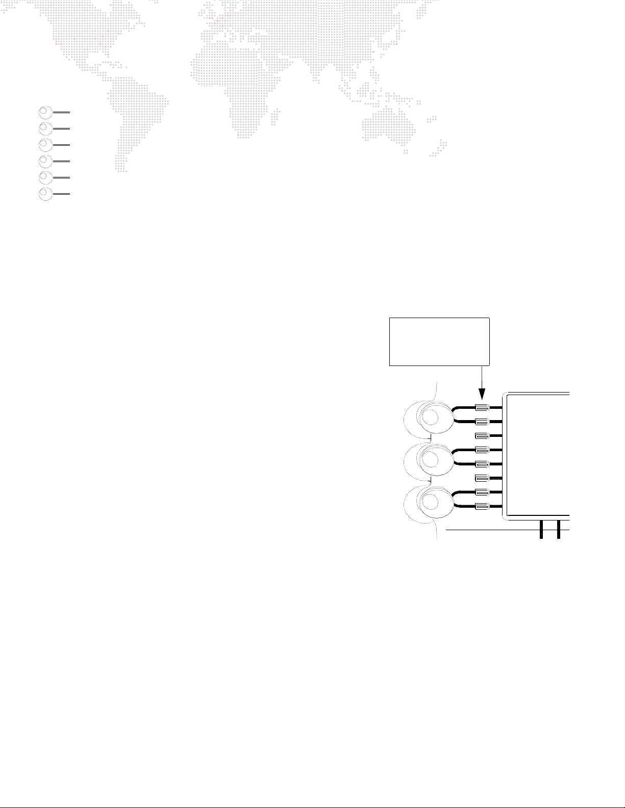
Effect
Min/Max Button Sends default setting
to selected channels.
(User programmable.)
When [Effect] is selected, the soft encoder mapping is as follows:
Fade Out (0.0)
Fade In (0.0)
Decay (0.0)
Sustain (0.0)
Attack (0.0)
Step (0.0)
Refer to the "Effects" chapter on page 169 for more information about using the encoders with effects.
Storing New Default Minimum/Maximum Settings (V476/V676 Only)
The min/max buttons associated with each function can be programmed with your own default settings as required.
These settings are referred to as hard/soft, in/out, etc. depending on the mechanism being controlled. The initial
console default settings (which correspond to the luminaire’s actual min/max values) can be re-stored with your own
min/max settings.
The min/max settings are based on channel selection. This means that a
different minimum and maximum setting can be defined for every channel
or for groups of channels as required. For example, if Channel 1 is patched
as a Bad Boy® luminaire you could select its channel and then store
appropriate min/max settings. You could then deselect Channel 1 and
select Channel 2 (which, for example is patched as a VL6C+® luminaire)
and store different min/max settings. Depending on whether Channel 1 or
Channel 2 is selected, the min/max settings would be different.
Store new min/max settings:
Step 1. Press encoder function button as required (Color, Beam, Image,
etc.). The functions will be mapped to soft encoders.
Step 2. Select luminaires to be included in min/max setting.
Step 3. Using encoders, adjust parameter for new setting.
Step 4. Press and hold [Store] while pressing [Encoder Min/Max Button].
Setting is now stored for those channels.
Add new channels to a setting:
Step 1. Select luminaires to be added to setting. (For example, select
additional VL6C+ luminaires.)
Step 2. Press and hold [Store] while pressing [Encoder Min/Max Button]. Setting is now stored for new luminaires
as well as previously stored luminaires.
68 VX76 SOFTWARE USER MANUAL
Page 85
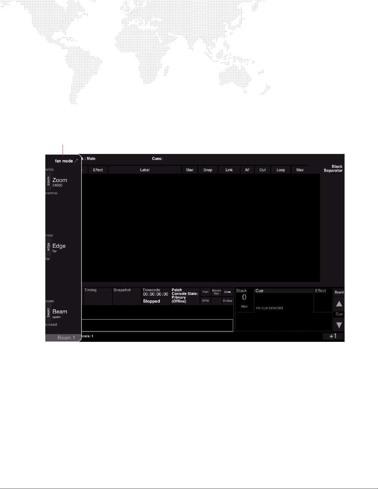
Sliding Encoder Sidebar (V476 Only)
Encoder Sidebar
CENTRAL DISPLAY
The sliding Encoder Sidebar is used with the six "soft" encoders available on the V476 front panel. The V676 has a
designated area for displaying encoder controls, but since the V476 desk is smaller, these controls are displayed
using the sliding sidebar. The sidebar appears in the same space as the central and palette displays when an encoder
is turned or an encoder function button is pressed.
Guidelines:
+ When an encoder is turned or an encoder function button is pressed, the sidebar will slide into view.
+ Press the encoder function button again to display the second page of options.
+ Double-click an encoder function button to lock the sidebar on.
VX76 SOFTWARE USER MANUAL 69
Page 86
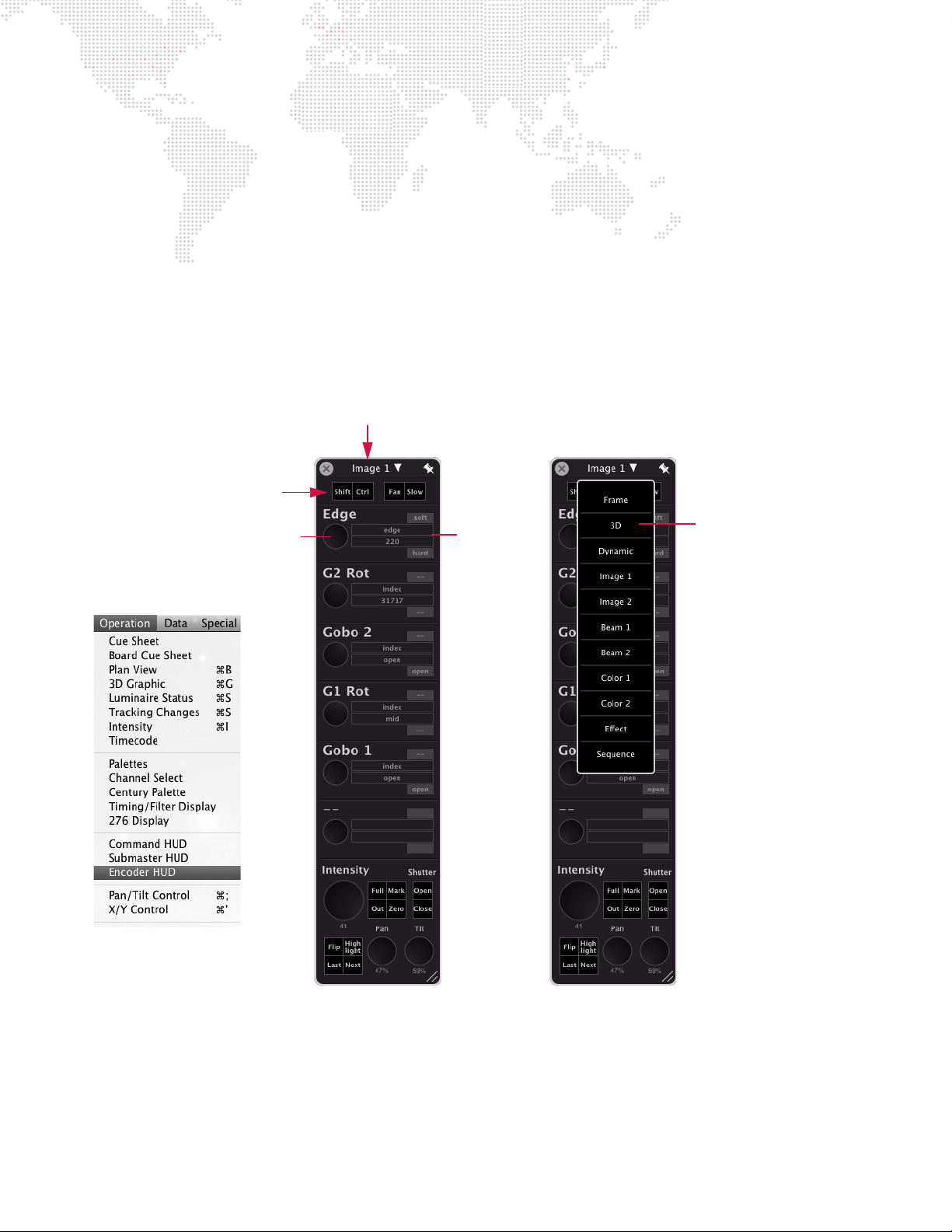
Encoders HUD Window
Encoder Selection Menu
Special Buttons
Virtual Encoder
Values
Current Encoder Type
The Encoders software window functions just as the front panel encoders to provide incremental control of luminaire
parameters. Refer to the function explanations in the section "Front Panel Encoders" on page 61 for more in-depth
information on each encoder function and the associated min/max settings.
To operate the window controls:
+ At Operation menu, select Encoder HUD to open Encoders window.
+ To use a virtual encoder, press and hold the mouse down on a knob, then drag the mouse up or down to increase
or decrease the parameter value.
+ Apply Shift, Control, Fan, and Slow features by clicking the buttons at the top of the window.
+ Switch between encoder types using the drop-down menu at the top of the window.
+ Click the pin icon at the top-right corner to keep the HUD on top of other windows. (When pinning is active, the
pin icon will turn from gray to white.)
Store new min/max settings:
Step 1. Select luminaires to be included in min/max settings.
Step 2. At Encoder window, select parameter group from drop-down menu.
Step 3. Using encoders in window, choose a parameter for new setting.
Step 4. Press and hold [Option], then click desired min/max button in window. Setting is now stored for those
channels.
70 VX76 SOFTWARE USER MANUAL
Page 87
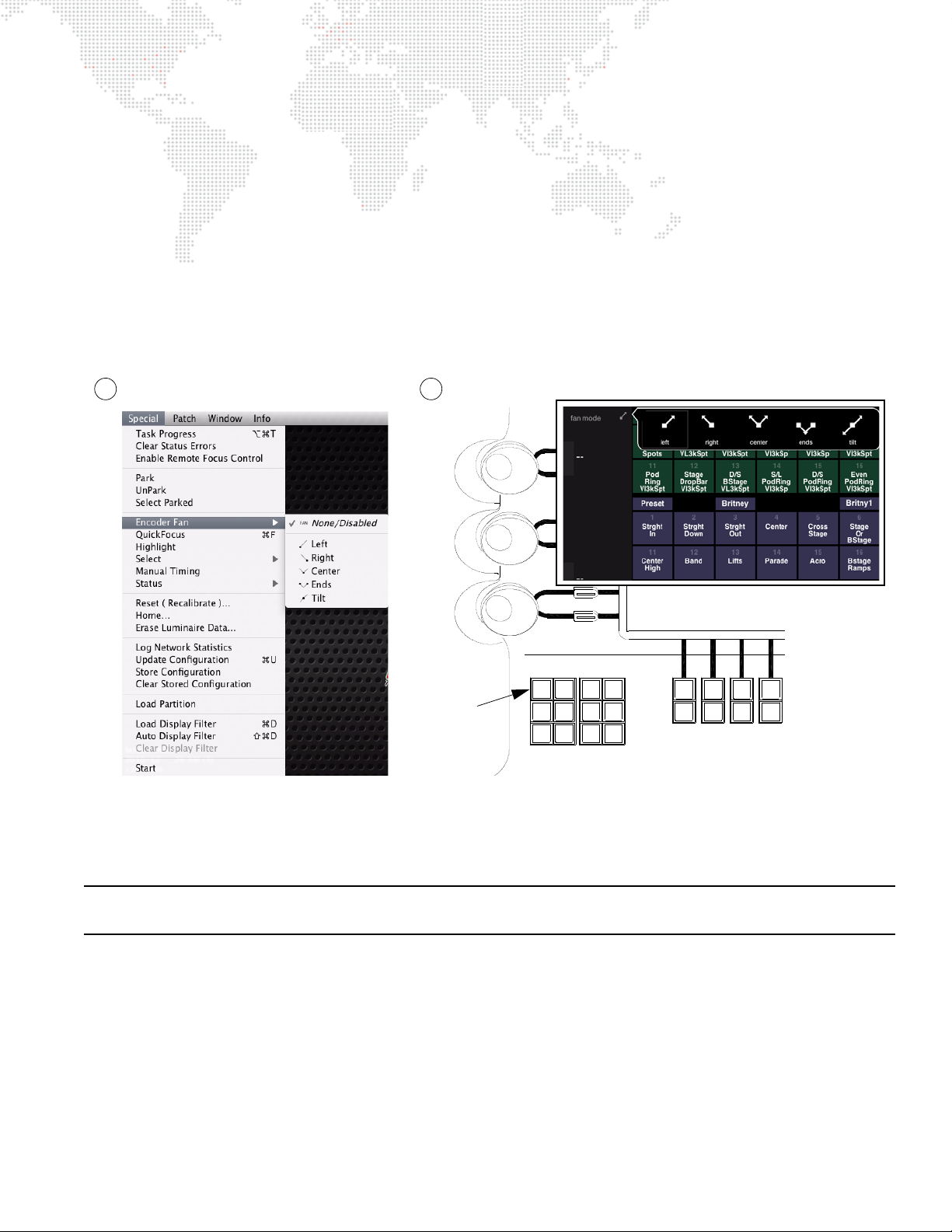
Fan
12 435 867
11 12 1413 15 1816 17
Fan Effect Frame Image
Slow 3D Beam
Shift Grid Dynam Color
Front Panel
Fan Button
2
Encoder Fan Menu
1
The Fan function allows "fanning" of any encoder-controlled parameter across multiple channels. For example, it
could be used to "fan" a dynamic across a group of luminaires in order to achieve a more random effect. It does this
by giving each channel an "offset" starting point so that each luminaire starts the action at a different time (instead of
simultaneously).
There are five fan mode types: Left fan, Right fan, Center fan, Ends fan, and Tilt fan. Each type uses a different anchor
point for the base of the fan. Fan ordering is determined by selection order.
The fan mode can be changed from two locations: the Special menu or the front panel. These operations are as
follows:
1) At Special menu, select Encoder Fan, then choose the mode.
2) At front panel, press
fan mode button, then choose the mode.
Once the fan mode is chosen:
+ At front panel, press and hold [Fan] button while turning an encoder. Double-clicking the [Fan] button will latch fan
Note: Timing and delay attributes can be "fanned" into channel selections using the soft encoders or command-line
keypad. Refer to "Fanned Timing and Delays" on page 92 for more information.
mode on (LED will flash). Double-click again to turn fan mode off.
VX76 SOFTWARE USER MANUAL 71
Page 88
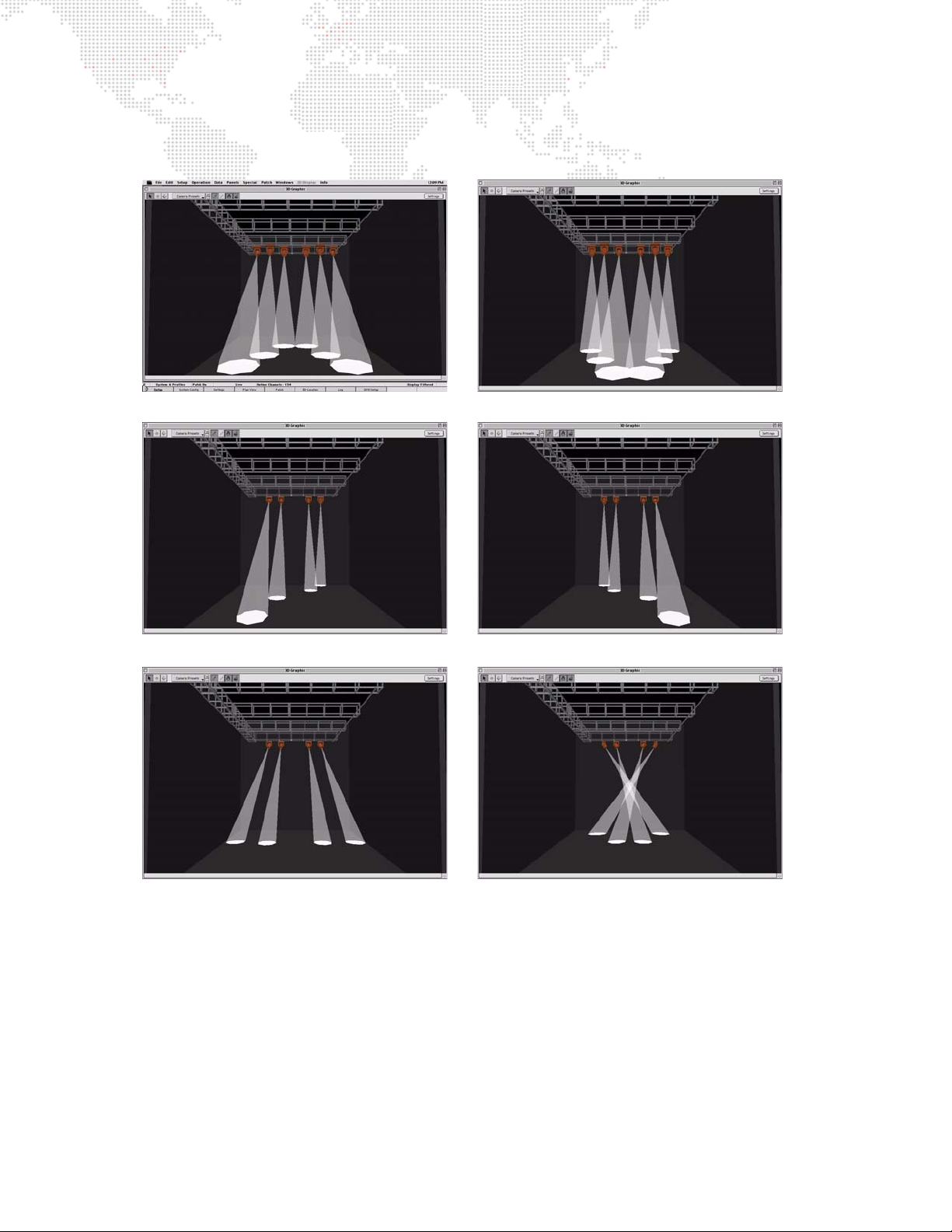
Encoder Fan Examples
Tilt Center Fan Tilt Ends Fan
Tilt Right Fan
Pan Out Fan Pan In Fan
Tilt Left Fan
The following are a few examples of fanning as shown in the 3D Graphic window:
72 VX76 SOFTWARE USER MANUAL
Page 89
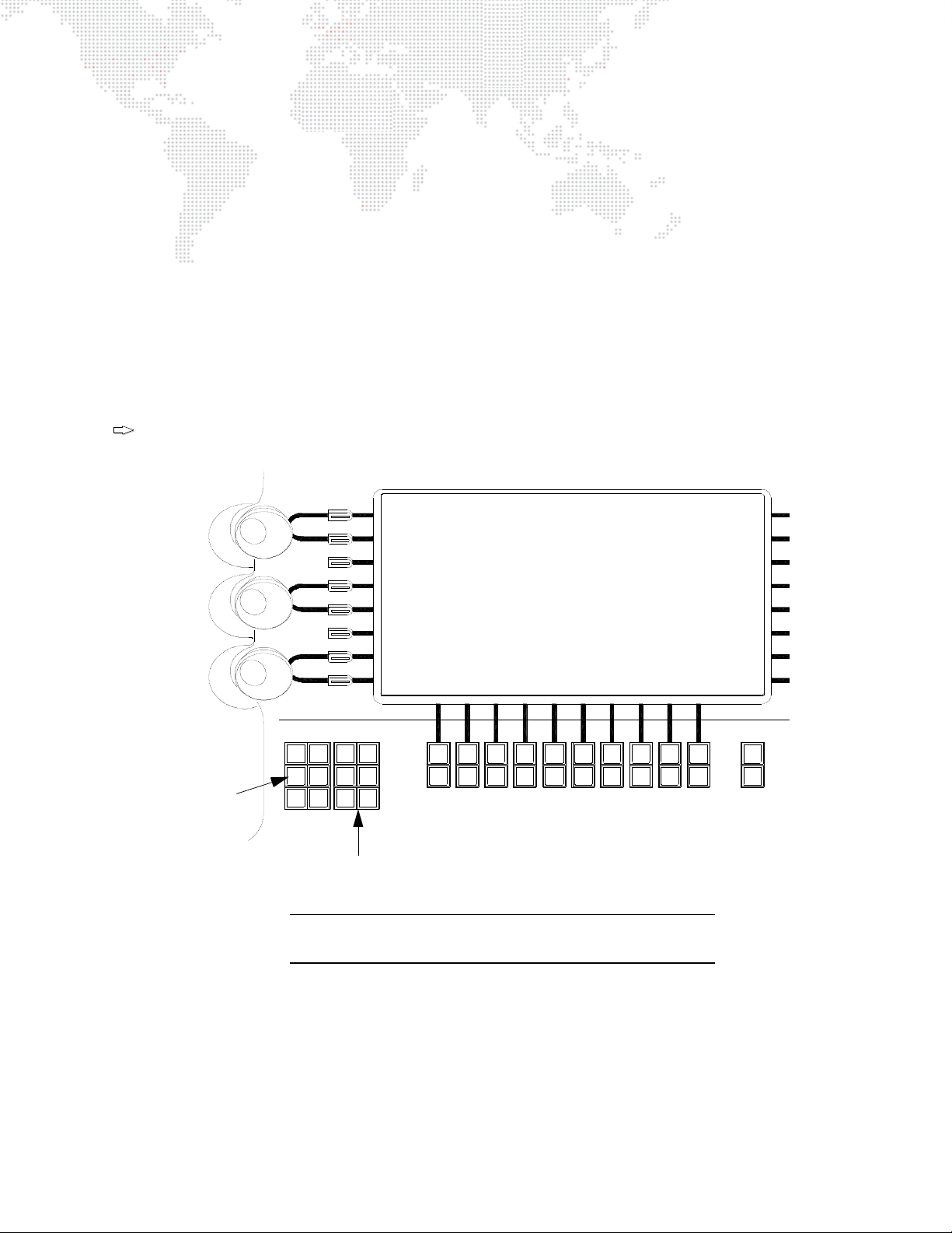
High Resolution Mode
Tip
12 435 867 910
11 12 1413 15 1816 17 19 20
Fan Effect Frame Image
Slow 3D Beam
Shift Grid Dynam Color
Bank
Func
Slow
Button
Function Buttons
(Image, Beam, Color, etc.)
Note: The V676 console is shown in this example, however,
these buttons are found on all Vx76 console front panels.
The encoder high resolution mode can be used for fine tuning luminaire parameters.
To turn on high resolution mode:
Step 1. At front panel, select desired encoder function (Preset, Color, Beam, etc.) by pressing its button.
Step 2. Double-click [Slow] button to latch high resolution mode on (LED will flash when enabled).
Step 3. Turn encoders to fine tune luminaire parameters.
Step 4. Double-click [Slow] button again to turn high resolution mode off.
To use high resolution "quick adjust" mode:
Step 1. At front panel, select desired encoder function (Preset, Color, Beam, etc.) by pressing its button.
Step 2. Press and hold down [Slow] button, while at the same time turning encoders. Adjustments to parameters
will be high resolution as long as [Slow] button is held.
This mode is also useful when controlling media server attributes.
Figure 3-5: Slow Button
VX76 SOFTWARE USER MANUAL 73
Page 90
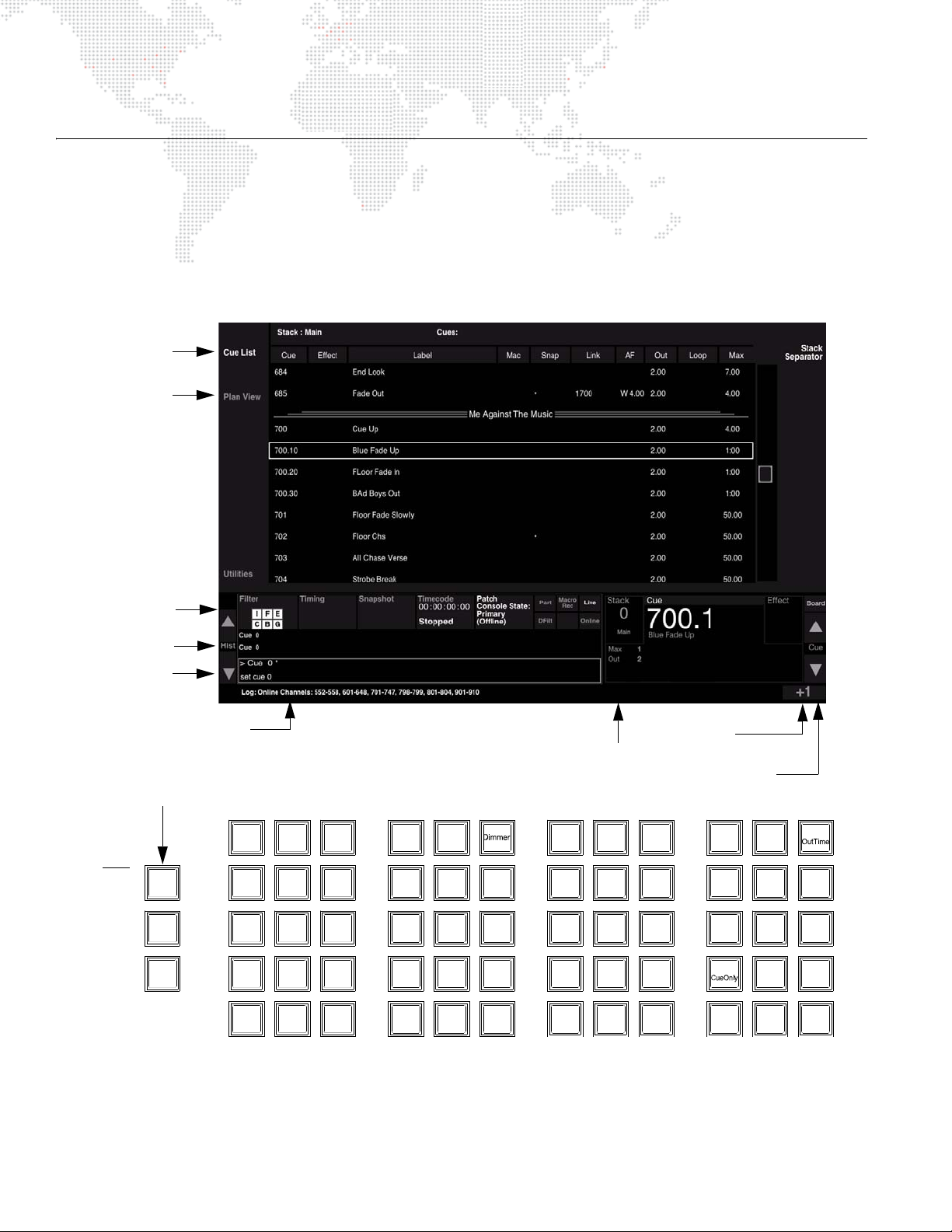
KEYPAD CONTROL
Command
Line
Log Line
Cue Advance
Arrows
Increment
Value
Display
Cue List
Display
Plan View
History
Arrows
Cue Info
Control (Command-Line) Keypad
Shift
Option
Cmd
123
.0
Clear
At EnterFull
789
Time
456
Sub
Rate
Link
+
Thru
-
Loop
Force
Mark
Cue/
Delay/
Speed
Track
Back
Track/
Wait/
Trail
SneakLabel
Move
Delete
Copy/
Sel
Park/
PatchUndoRecall
Store
Unpark
Update
Grab
Help
Query/
Store
Block/
UnBlk
Revert
Manual/
Effect Set Seq
DynamGroup Step
Snap
BeamColorPreset
Macro
Shot
Chan
Cue/
Stack
Board
Cue
Dashboard
Controls
Convenience Keys - provides a front panel
alternative to the Mac keyboard keys: Win
(Command), Alt (Option) and Shift.
WIN =
ALT =
SHIFT =
Mac
Keys
Overview
The control (or command-line) keypad also provides manual control of luminaires. Luminaire parameters can be set
from the keypad just as they can from the manual control encoders, although in most cases the Sneak function is also
required. This section will cover all manual controls that can be executed using the command-line keypad alone.
Advanced manual control using the keypad will be discussed along with the Sneak function in "Timing, Filters and
Sneak" chapter on page 85.
Entries made with the keypad are referred to as "command-line entries" and will be displayed in the command-line
display as they are entered.
74 VX76 SOFTWARE USER MANUAL
Page 91

Command-line entry guidelines:
store color 8
Store Color 8
*
sel recall preset 15
Recall Preset 15
*
Tip
+ When entering command lines, it is not necessary to specify channel information if the required channels are
already selected. If new channels are selected for modification on the keypad, this is reflected at the Channel
Select panel.
+ [Clear] functions as a backspace key when used during command-line construction. [Clear] is the only thing that
clears a syntax error. (Any other keypad entry is ignored until the error condition is cleared.)
+ When working from the command-line keypad, parameters will assume their new values at full speed unless
Manual Timing is currently enabled, in which case they will use their current timing values. Only when used with
the Sneak function can the keypad selections be assigned discrete timing values.
+ Since manual control requires channel selection, this can also be done using the command-line keypad. Refer to
Channel Select "From Keypad" on page 56.
Holding down [Clear] will clear an entire unterminated command line.
VX76 SOFTWARE USER MANUAL 75
Page 92

Setting Parameters From Keypad
Presets
The keypad can be used to assign presets to selected luminaires. The preset entered on the keypad corresponds to
the preset saved in that particular Preset palette (refer to "Presets" on page 116).
Examples:
+ <Chan> [n] [Preset] [m] [Enter] - applies preset m to the selected channel n (where m is the discrete preset
number).
+ <Chan> [n] [Thru] [q] [Preset] [m] [Enter] - applies preset m to the selected range of channels (where m is the
discrete preset number).
Colors
The keypad can be used to assign colors to selected luminaires. The color entered on the keypad corresponds to the
color saved in that particular Color palette (refer to "Colors" on page 121).
Examples:
+ <Chan> [n] [Color] [m] [Enter] - applies color m to the selected channel n (where m is the discrete color number).
+ <Chan> [n] [Thru] [q] [Color] [m] [Enter] - applies color m to the selected range of channels (where m is the
discrete color number).
Beams
The keypad can be used to assign beams to selected luminaires. The beam entered on the keypad corresponds to
the beam state saved in that particular Beam palette (refer to "Beams" on page 125).
Examples:
+ <Chan> [n] [Beam] [m] [Enter] - applies beam state m to the selected channel n (where m is the discrete beam
number).
+ <Chan> [n] [Thru] [q] [Beam] [m] [Enter] - applies beam state m to the selected range of channels (where m is the
discrete beam number).
Note: If a profile does not provide default color and beam data, then there will be no change for selected channels
until custom color and beam palettes are stored.
76 VX76 SOFTWARE USER MANUAL
Page 93

Intensity
Tip
The keypad can be used to adjust the brightness of the luminaire’s beam. Intensity responds to a percentage value of
0-100.
The [At] button is used to enter intensity values:
+ <Chan> [n] [At] [m] [Enter] - changes the intensity level of the selected channel to m.
+ <Chan> [n] [Thru] [q] [At] [m] [Enter] - changes the intensity level for the selected range of channels to m.
The [Full] button is used to quickly set intensity to 100%.
+ <Chan> [n] [Full] [Enter] - changes the intensity level of the selected channel to 100%.
The [+] and [-] buttons can be used in combination with the [At] button to increment or decrement a current intensity
value by a specific amount. For example, if the current intensity value is 50%:
+ <Chan> [n] [At] [+] [0] [5] [Enter] - increases the intensity level of the selected channel to 55%.
+ <Chan> [n] [At] [-] [0] [5] [Enter] - decreases the intensity level of the selected channel to 45%.
To quickly enter an intensity below 91%, but divisible by 10, use only the first digit of the desired level (for
example, [At] [5] = 50%).
To Mark a channel on the command line, enter the following sequence:
+ [Chan] [n] [At] [At] [Enter]
VX76 SOFTWARE USER MANUAL 77
Page 94
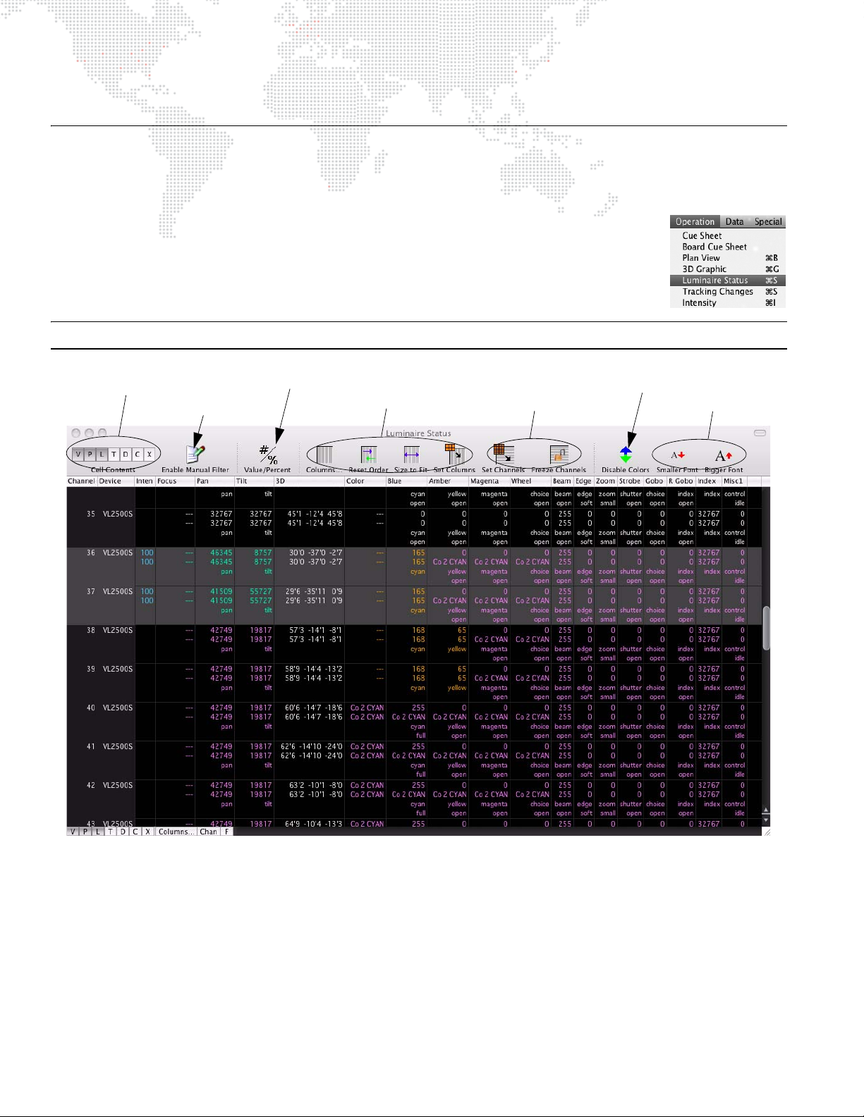
LUMINAIRE STATUS
Column Settings
Channel Controls
Font Settings
Window Display Settings
Toggle Value or Percent Data
Enable/Disable Color Coding
Manual Filter
Luminaire Status Window
Overview
The Luminaire Status window can be used to view current luminaire data as a numeric value or
preset reference. (The window is merely a way to display and review data and does not provide
editing functions.)
+ At Operation menu, select Luminaire Status. (Data will be displayed for all luminaires.)
Note: Multiple Luminaire Status windows can be open at the same time with different settings for each.
The parameter columns which are displayed can be changed via the Parameter Columns window. Refer to
"Parameter Columns Window" on page 82.
78 VX76 SOFTWARE USER MANUAL
Page 95

Display Settings
Use the following buttons to display different types of data:
+ Value (V) - displays the numeric value currently being received by the luminaire for each parameter.
+ Parameter (P) - displays the Preset, Color or Beam which the parameter is currently referencing (default setting).
+ Shifted Parameter (S) - displays any shifted parameters which have been set at encoders.
+ Timing (T) - displays any associated timing information.
+ Dynamic (D) - displays any associated dynamic state information and continuous action such as wheel spins.
+ Cue Source (C) - displays the source cue for each parameter.
+ Execution Time (X) - displays remaining execution and delay times.
+ Column Window (Columns...) - opens parameter column window that determines which parameters are
displayed.
+ Set Channels (Chan) - sets channels from the current channel selection, as limited by the display filter (toggle
action). (Refer to "Display Filters" on page 311.)
+ Freeze Channels (F) - channels are set to the currently visible channels, and are not affected by subsequent
changes to the global display filter (toggle action).
Keyboard Shortcuts and Tips
+
WIN + R = Reset Order
+
WIN + SHIFT + R = Size To Fit
+ Holding down
ALT on the Mac keyboard or [Option] on the front panel and clicking a column will lock the column
in place. (Note that locked columns will be moved to the left of the unlocked columns.)
+ Click on a column’s header and drag to reposition the column.
+ Hold the cursor over the toolbar icons to view "What’s This?" text.
Color Coding
The Luminaire Status values are color coded in order to provide useful information regarding how the values are
changing from cue to cue, and if a value comes from manual control or an effect. Color indications are as follows:
Magenta
= unchanged values.
Blue
= increasing intensity values.
Green
= decreasing intensity values.
Orange
= values changed by manual control.
Gray
= values changed by an effect.
Brown
= values changed by another console.
Changing Data Values
Data values can be increased or decreased for the selected luminaires by clicking on a column header and then
holding down the
When working with either the Pan or Tilt columns, pressing
CTRL button on the Mac keyboard while pressing the keyboard’s up/down arrows.
CTRL + SHIFT + UP or DOWN arrow will increment or
decrement the alternate parameter (Tilt when Pan is selected and vice versa).
VX76 SOFTWARE USER MANUAL 79
Page 96
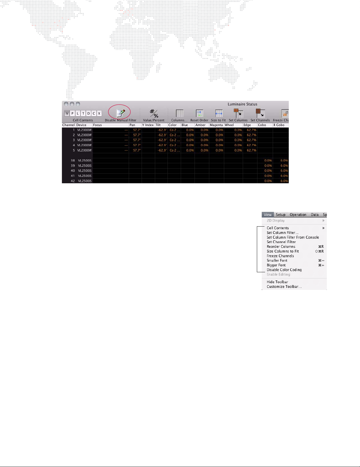
Manual Change Filter
The Luminaire Status window provides a method for displaying only channels and parameters that have been
modified manually. This provides a quick way to see which channels have been modified from recalled cues.
To use the Manual Filter:
+ Click Enable Manual Filter icon to display manually modified channels.
+ To disable Manual Filter, click Disable Manual Filter icon.
Customizing Luminaire Status Window
The Luminaire Status Window can be customized using:
+ Column resizing, including Size Columns To Fit in View Menu. (Click on the
column divider to resize.)
+ Column repositioning. (Click on column header and drag to new position.)
+ Font resizing.
+ Value/Percent display option.
+ Color coding.
+ Set columns with current function filter.
+ Set channels from the current channel selection. (The displayed channels will still
also be limited by the display filter.)
+ Freeze channels. (When frozen, the table’s channels are set to the currently visible channels, and are not affected
by subsequent changes to the global display filter.).
To customize window:
+ At View menu, select parameter to update window configuration.
80 VX76 SOFTWARE USER MANUAL
Page 97
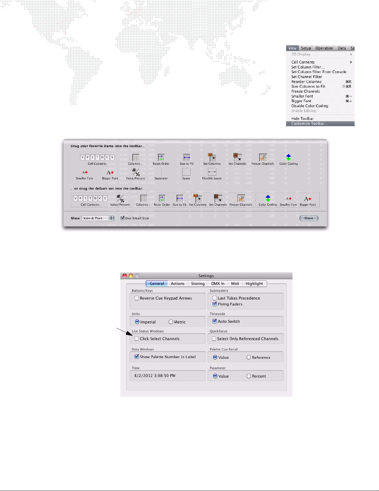
Customizing Luminaire Status Toolbar
Allows channel selection
in Status windows
The Luminaire Status Window toolbar can be customized using the Customize Toolbar
window.
To customize toolbar:
Step 1. At View menu, select Customize Toolbar.
Step 2. Drag icons or default set into toolbar.
Selecting Channels from Luminaire Status Window
Channels can be selected from the Luminaire Status window by clicking in the channel field. (This must first be
configured in Settings window as shown below.)
VX76 SOFTWARE USER MANUAL 81
Page 98
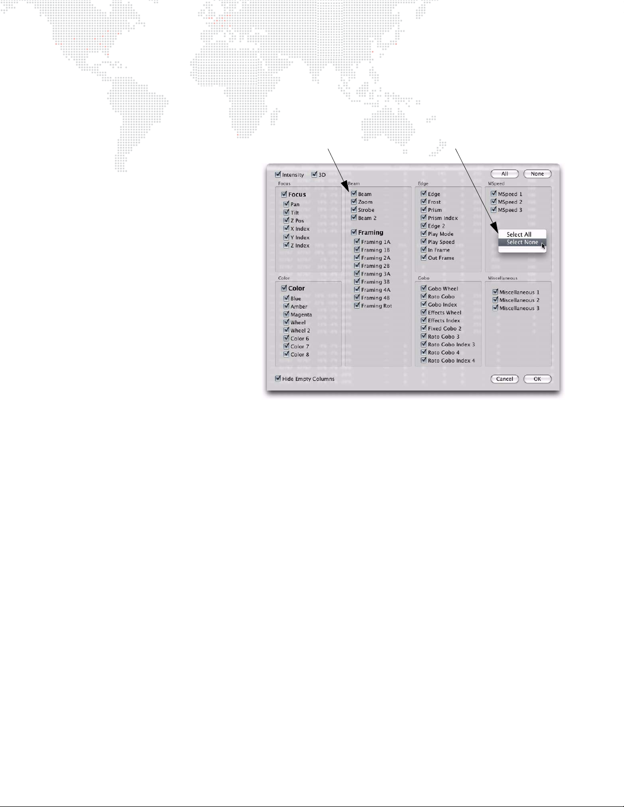
Parameter Columns Window
Right-click with mouse or trackpad
to bring up shortcut options.
Parameters with a checked
box will be displayed in window
The Parameter Columns window is used to define which types of information will be displayed in the data window
(columns). Using the cursor, select or deselect the boxes as required.
For Focus and Color, two display options are
available. Focus can be displayed as a single
column and/or two columns, pan and tilt. Color
can likewise be displayed as a single column
and/or up to four individual color columns,
which would provide data for each filter/wheel/
plate mechanism in the luminaire. When the
single Focus/Color box is checked, the column
will display the Preset/Color source, as long as
the data is being taken from a single Preset/
Color. If not from a single Preset/Color, then
the column would display "---." If Pan/Tilt, etc.
are checked then those columns also display
the source, or if set by encoders, the numerical
values. To see both source and # values, select
[P] and [V] (at Luminaire Status window).
82 VX76 SOFTWARE USER MANUAL
Page 99
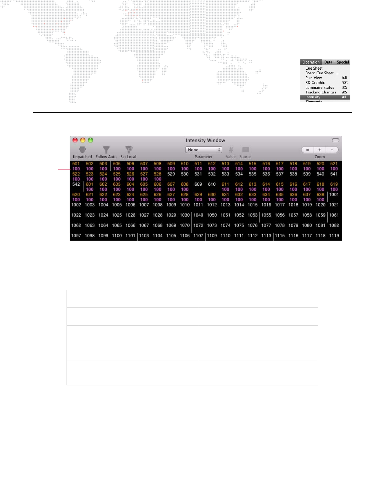
Intensity Window
Intensity
Values
The Intensity window can be used to view intensity values for all patched channels. Selections
made at the Channel Select window or panel and/or command-line keypad are highlighted in
the window and subsequent changes to intensity values are reflected in the display.
+ At Operation menu, select Intensity.
+ Using manual controls, change intensity values as required. Changes will be reflected in
display.
Note: Multiple Intensity windows can be open at the same time with different settings for each.
Color Coding
Color coding of the intensity values provides useful information regarding how the channels are changing from cue to
cue, and if an intensity level comes from manual control or an effect. The coloring of channel numbers and intensity
values provide the following indications:
Magenta
= unchanged values.
Blue
= increasing intensity values.
Green
= decreasing intensity values.
Pink
= channels with the same cue intensity (tracking).
Red Underline
= channels which are not outputting the given intensity value. This will occur when a channel’s intensity value is being reduced by the grandmaster or an inhibitive submaster.
For example, if channels are brought up manually using an encoder, the channel numbers turn to
Yellow Background
= values changed by manual control.
White
= values changed by an effect.
Brown
= values changed by another console.
Red Box
= parked channels.
red
to indicate that
they are manually controlled. Next, if a cue is played back which overrides the intensity of these channels (HTP), the
values would be displayed in blue - refer to "HTP (Highest Takes Precedence)" on page 301. (If the cue does not
override the intensity, they would remain in the manual control state color.) If another cue is played back in which the
channels in blue fade down or out, they would change to green during the fade.
VX76 SOFTWARE USER MANUAL 83
Page 100
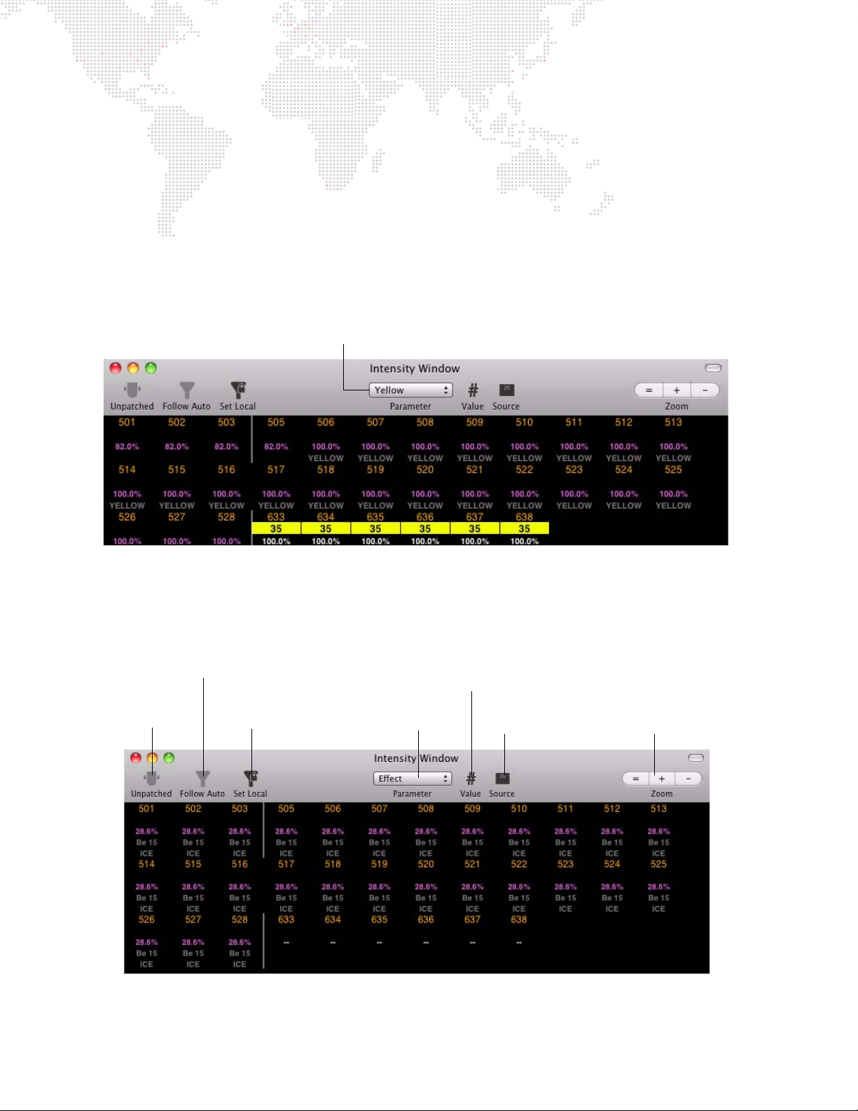
Configuring How Information is Displayed
Parameter Pop-up Menu
Show/Hide
Unpatched
Channels
Enable/Disable Follow
Auto Display Filter
Set Local Display Filter
Parameter
Selection
Show Value, %,
and/or Label
Show Source Number
and/or Source Label
Zoom Controls
In the window’s default state, all patched channels are listed horizontally with a vertical line inserted between nonconsecutive channel numbers.
User defined columns: All channels shown with unpatched channels grayed out, width of window can be changed to
modify the number of channels displayed in each row, scroll bar allows access to all channels.
Displaying an Additional Parameter
The Intensity window can display an additional parameter below the intensity level. This can be used for scrollers to
show the color value, or for any other single parameter. Once selected, the window will display the parameter type at
the top. The default setting is "none."
+ To display an extra parameter, choose one from the Parameter pop-up menu.
Configuring Other Window Options
The icons at the top of the Intensity window can be used to configure what kind of information is displayed in the
window. When enabled, an icon will be dark; when disabled, it will be grayed out.
84 VX76 SOFTWARE USER MANUAL
 Loading...